JP4635331B2 - Printed wiring board - Google Patents
Printed wiring board Download PDFInfo
- Publication number
- JP4635331B2 JP4635331B2 JP2000374980A JP2000374980A JP4635331B2 JP 4635331 B2 JP4635331 B2 JP 4635331B2 JP 2000374980 A JP2000374980 A JP 2000374980A JP 2000374980 A JP2000374980 A JP 2000374980A JP 4635331 B2 JP4635331 B2 JP 4635331B2
- Authority
- JP
- Japan
- Prior art keywords
- hole
- conductive material
- insulating substrate
- conductive
- printed wiring
- Prior art date
- Legal status (The legal status is an assumption and is not a legal conclusion. Google has not performed a legal analysis and makes no representation as to the accuracy of the status listed.)
- Expired - Fee Related
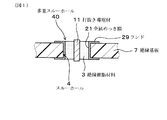
Links
Images
Landscapes
- Production Of Multi-Layered Print Wiring Board (AREA)
- Printing Elements For Providing Electric Connections Between Printed Circuits (AREA)
Description
【0001】
【技術分野】
本発明は,プリント配線板に関し,特に導電性に優れた多重スルーホールに関する。
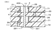
【0002】
【従来技術】
プリント配線板には,導体層間の導通を行うためにスルーホールが設けられている。スルーホールは,一般に,内壁が金属めっき膜により被覆されている。
また,近年,プリント配線板の多層高密度配線化が進み,それに伴いスルーホールの構造も様々に工夫されている。
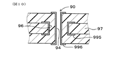
その一例として,図10に示すごとく,外側スルーホール96の中に内側スルーホール94を設けた多重スルーホール90が考えられている。この多重スルーホール90では,たとえば,内側スルーホール94に信号回路を,外側スルーホール96に電源回路または接地回路を接続して,異種電位にすることができる。
【0003】
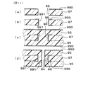
上記多重スルーホール90を形成するにあたっては,図11(a)に示すごとく,銅箔990を上下両面に貼り合わせた絶縁基板97を準備し,ドリルにより外側スルーホール96を穿設する。次いで,図11(b)に示すごとく,外側スルーホール96の内部に金属めっき膜991を被覆し,その後銅箔990をパターニングして,内層としての導体回路995を形成する。
【0004】
次に,図11(c)に示すごとく,絶縁基板97の上下両面に絶縁樹脂層95を形成し,その表面に銅箔990を貼着する。
次に,図11(d)に示すごとく,ドリルにて,外側スルーホール96の中心部分を貫通する内側スルーホール94を穿設する。次に,内側スルーホール94の内壁を金属めっき膜991により被覆し,その後銅箔990をパターニングして外層としての導体回路996を形成する。
【0005】
【解決しようとする課題】
しかしながら,上記従来のプリント配線板においては,外側スルーホール96及び内側スルーホール94の双方に,金属めっき膜を形成する必要がある。このため,スルーホールの長さが長いと,めっき液がスルーホール内部まで浸入しない場合がある。それゆえ,スルーホール内部に金属めっき膜を形成することが困難となり,導電性不良となる場合がある。特に,外側スルーホール96よりも細く且つ長い内側スルーホール94に特に顕著に生じる問題である。
【0006】
本発明はかかる従来の問題点に鑑み,導電性に優れた多重スルーホールを有するプリント配線板を提供しようとするものである。
【0007】
【課題の解決手段】
請求項1の発明は,絶縁基板を貫通し内壁が導電膜により被覆されているスルーホールを有し,
該スルーホールには絶縁樹脂材料が充填されているとともに,該絶縁樹脂材料の中心部分には導電材が埋め込まれているプリント配線板において,
同一位置に上記スルーホールを有する複数の第一絶縁基板を,第二絶縁基板を介して積層圧着するとともに,
上記第一絶縁基板は,上記スルーホールと,その内部に充填された上記絶縁樹脂材料と,該絶縁樹脂材料の中心部分に埋め込まれた上記導電材とを有し,
上記第二絶縁基板には導電材が埋め込まれており,
上記第一絶縁基板における上記導電材は,上記第二絶縁基板に埋め込まれた上記導電材を介して電気的に接続されていることを特徴とするプリント配線板である。
【0008】
本発明のプリント配線板は,スルーホールの内壁に導電膜を形成し,中心部分には導電材を埋めこんでいる。すなわち,このスルーホールの周縁部分には導電膜からなる導電路を,その中心部分には導電材からなる導電路を備えた多重スルーホールである。
ここで,多重スルーホールの中心部分には,従来のめっき膜に代えて,上記導電材を設けているため,従来のようなめっき液のスルーホール内部浸入不十分に起因する導通不良の問題を回避することができる。
また,中心部分の導電材と外側の導電膜との間には,絶縁樹脂材料が介設されているため,両者間の絶縁性を確保できる。このため,両者に異なる電位の電流を流すことができる。
更に,本発明においては,第一絶縁基板のスルーホール内に埋め込まれた導電材と,第二絶縁基板に埋めこまれた導電材とが連結される。このため,複数の絶縁基板を貫く導通ビアを形成することができる。また,一連のスルーホールに複数の電位の電流を導通させることができる。このため,上下間の導通を小スペースで行うことができる。
【0009】
スルーホールの中心部分に埋め込まれる上記導電材は,ハンダからなることが好ましい。ハンダは比較的低温で溶融するため,導電材が相手部材の導体と接合しやすくなるからである。
上記導電材は少なくとも一方の端部が比較的低温で溶融する材料例えば,ハンダや導電性ペーストであって,芯となる部分端部に比べて高融点であるが銅,銀,錫,鉛,ニッケルを主とする金属材料からなる2あるいは3層構造である方が更に良い効果をもたらす。その場合,低融点の端部の材料の厚みは少なくとも,0.005mmあれば,対向する導体と効率よく,強度の高い接続を得る事ができる。
【0010】
請求項2の発明のように,上記導電材は,打抜き導電材であることが好ましい。打抜き導電材は,パンチなどによる打ち込みという簡易な方法によってスルーホール内に埋め込むことができるため,多重スルーホールの形成が容易となる。
上記打抜き導電材としては,たとえば,導電性シートを打抜いたものを用いることができる。導電性シートとしては,銅箔,ハンダ箔,金属粉末が樹脂の中に分散した導電性フィルム,加圧によって導電性を発揮する異方性導電性フィルムなどを用いることができる。
【0011】
上記打抜き導電材をスルーホールの中心部分に配置させるにあたっては,たとえば,上記のごとく絶縁基板のスルーホールに絶縁樹脂材料を充填しておき,次いでこの絶縁基板の上に導電性シートなどの導電性物質を配置し,パンチによりこれらを打抜いて打抜き導電材を形成するとともに,打抜き導電材を,絶縁樹脂材料に形成された打抜き穴の中に埋め込む。
【0012】
スルーホール内壁は導電膜により被覆されている。請求項3の発明のように,上記導電膜は,金属めっき膜であることが好ましい。外側に位置するスルーホールは導電材よりも径が大きく,薄い金属メッキ膜であっても,導電断面積が比較的大きくすることができる。この時の金属メッキ膜の厚みは少なくとも0.003mmであり,厚くとも0.03mmであることが好ましい。
そして,スルーホール径は0.200mmまで小さくすることができ,導電材は0.05mmまで小さくすることができる。
ここで,導電材の両端部はスルーホールに形成される金属メッキ膜よりも突出している方が好ましい。これにより複数のスルホールを積層する時により効率的に接続することができる。窪んでいても良いが,その場合は対向する導電材は突出していることが必要である。
【0013】
または,請求項4の発明のように,上記導電膜は,筒状打抜き導電材であることが好ましい。筒状打抜き導電材では,金属メッキ膜よりも比較的厚い導電性の断面が得られるため,比較的高い電圧が通電する電源用またはグランド用のスルーホールとして利用することができる。この時の導電膜の厚みは少なくとも0.030mmであり,厚くとも0.200mmであることで,高い電圧を少ない抵抗で効率的に通電することができる。
そして,この場合,スルーホール径は0.300mmまで小さくすることができる。
筒状打抜き導電材をスルーホール内に形成するにあたっては,絶縁基板のスルーホール形成部分に導電材を埋め込み,次いでその周縁を残して中心部分を筒状に打抜く。
【0014】
上記請求項1の発明においては,同一位置に上記スルーホールを有する複数の第一絶縁基板を,第二絶縁基板を介して積層圧着するとともに,
上記第一絶縁基板は,上記スルーホールと,その内部に充填された上記絶縁樹脂材料と,該絶縁樹脂材料の中心部分に埋め込まれた上記導電材とを有し,
上記第二絶縁基板には導電材が埋め込まれており,
上記第一絶縁基板における上記導電材は,上記第二絶縁基板に埋め込まれた上記導電材を介して電気的に接続されている。
これにより,第一絶縁基板のスルーホール内に埋め込まれた導電材と,第二絶縁基板に埋めこまれた導電材とが連結される。このため,複数の絶縁基板を貫く導通ビアを形成することができる。また,一連のスルーホールに複数の電位の電流を導通させることができる。このため,上下間の導通を小スペースで行うことができる。
【0015】
この場合,第一絶縁基板における導電材は,第二絶縁基板における導電材と同一位置に形成されていることが好ましい。これにより,導電性が更に向上する。
この場合,上記第一,第二絶縁基板の上記導電材における少なくとも相手部材と接合する部分は,絶縁基板の圧着時の熱で溶融し得る低融点材料であることが好ましい。低融点材料としては,半田,導電性金属を分散した樹脂ペーストなどがある。
【0016】
【発明の実施の形態】
参考例1
本発明の参考例に係るプリント配線板について,図1〜図4を用いて説明する。
本例のプリント配線板は,図1,図2に示すごとく,絶縁基板7を貫通するスルーホール4を有している。スルーホール4の内壁は,導電膜としての金属めっき膜21により被覆されている。スルーホール4の中は,絶縁樹脂材料3が充填されており,その中心部分には打抜き導電材11が埋め込まれている。
図2に示すごとく,スルーホール4の開口周縁部は,ランド29を介して,導体回路25と接続されている。打抜き導電材11は,チップ,マザーボードなどの相手部材と接続するために形成された接続パッドにも成りうる。
【0017】
次に,本例のプリント配線板の製造方法について説明する。
まず,図3(a)に示すごとく,絶縁基板7として厚み0.060mmのガラスエポキシ基板を準備し,その上下両面に銅箔2を貼着する。次いで,絶縁基板7にドリルにより,直径0.400mmのスルーホール4を穿設する。
次いで,図3(b)に示すごとく,無電解銅めっき及び電解銅めっきにより,スルーホール4の内壁に金属めっき膜21を形成する。この時の厚みは0.015mmである。次いで,銅箔2をエッチングして,ランド29及び導体回路25を形成する。
【0018】
図3(c)に示すごとく,印刷により,スルーホール4の内部に,絶縁樹脂材料3を充填する。絶縁樹脂材料3としては,シリカを主とする無機フィラーの50wt%含有したエポキシ樹脂である。
図4(a)に示すごとく,絶縁基板7の上に導電性シート1を配置し,これらをダイ62の上に載置する。また,スルーホール4の中心部分の上方に,打抜き用の上パンチ61を配置させる。導電性シート1としては,半田箔を用い,その厚みは0.080mmである。ダイ62における,スルーホール4の中心部分に対応する位置には,上パンチ61を上下にスライドさせ得るガイド穴63を設けてある。上パンチ61及びガイド穴63の直径は,それぞれ0.090mm,0.100mmである。
【0019】
次に,図4(b)に示すごとく,上パンチ61を下方にスライドさせて,導電性シート1を打抜く。これにより,導電性シート1に打抜き穴10が形成されるとともに,そこから円柱状の打抜き導電材11が形成される。また,これにともない,打抜き導電材11がその下方に位置する絶縁樹脂材料3の中心部分を打抜き,打抜き穴30を形成するとともに,その中に打抜き導電材11を埋め込む。打抜き穴30からは打抜き絶縁材31が形成される。打抜き導電材11の直径は,上パンチ61と同じである。以上により,中心部分に打抜き導電材11を,周縁部分に金属めっき膜21を配置した多重スルーホール40が形成される。
【0020】
本例においては,図1に示すごとく,スルーホール4の中心部分には,従来のめっき膜に代えて,打抜き導電材11を設けている。このため,従来のようなめっき液のスルーホール浸入不十分に起因する導通不良の問題を回避することができる。また,中心部分の打抜き導電材11と外側の金属めっき膜21との間には,絶縁樹脂材料3が介設されているため,両者間の絶縁性を確保できる。また,異種電気を導通させることができる。
【0021】
参考例2
本例は,図5に示すごとく,打抜き導電材11をスルーホール4内へ埋め込む際に,打抜き用の上パンチ61だけでなく,戻し用の下パンチ64も用いている点が,参考例1と異なる。
図5(a)に示すごとく,打抜き前では,下パンチ64は,ダイ62のガイド穴63の中に配置させる。下パンチ64は,上パンチ61により打抜かれた打抜き導電材11及び打抜き絶縁材31を受ける。続いて,図5(c)に示すごとく,上パンチ61及び下パンチ64を上方に戻し,打抜き導電材11を絶縁樹脂材料3の打抜き穴30内に戻し入れる。以上により,多重スルーホール40が形成される。
本例においても,参考例1と同様の効果が得られる。
【0022】
参考例3
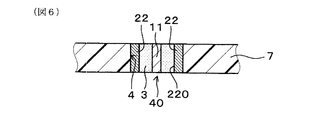
本例は,図6に示すごとく,スルーホール4内壁の被覆を,金属めっき膜に代えて,筒状打抜き導電材22により行った例である。この筒状打抜き導電材22は多重スルーホール40の周縁部分に,円柱状の打抜き導電材11は中心部分に配置されている。
【0023】
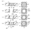
多重スルーホール40の形成方法を図7を用いて説明する。図7の左側にはその形成工程中の絶縁基板の多重スルーホール形成部分の厚み方向断面図を,右側にはその部分の平面方向平面図を示した。
まず,図7(a)に示すごとく,絶縁基板7に打抜き導電材2を埋め込む。埋め込みは,上記参考例1,2で説明した,図4または図5に示す方法にて行う。打抜き導電材2の直径は,0.600mmである。
次に,図7(b)に示すごとく,打抜き導電材2の中心部分を打抜き,打抜き穴220を形成する。これにより,厚み0.100mmの筒状打抜き導電材22が形成される。
【0024】
次に,図7(c)に示すごとく,印刷法で,筒状打抜き導電材22の中に,絶縁樹脂材料3を充填する。次に,図7(d)に示すごとく,絶縁樹脂材料3の中心部分に,図4又は図5に示す方法により,直径0.150mmの円柱状の打抜き導電材11を埋め込む。以上により,周縁部分に打抜き導電材11を,中心部分に筒状打抜き導電材22を配置した多重スルーホール40が形成される。
本例においては,多重スルーホール40の中心部分だけでなく,周縁部分も,打抜き導電材により導通を付与している。このため,多重スルーホールを容易に形成することができる。
【0025】
実施形態例1
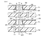
本例は,図8,図9に示すごとく,4枚の絶縁基板を積層した多層のプリント配線板である。そのうちの2枚の第一絶縁基板71に,参考例1と同様の,多重スルーホール40及び導体回路25を設け,他方の2枚の第二絶縁基板72には打抜き導電材11を埋め込み,導体回路251を形成する。多重スルーホール40と打抜き導電材11は,同一位置に形成する。そして,図9に示すごとく,第一,第二絶縁基板71,72を4枚積層し圧着すると,これらを貫通する導通ビア400が形成される。導通ビア400の中心に配置した打抜き導電材11は,第二絶縁基板72に設けたランド291を介して導体回路251と電気的に接続されている。
【0026】
打抜き導電材11は,絶縁基板71,72の圧着時の熱で溶融する材料(例えば,半田)からなる。
また,導体回路25にパッド部26を設け,そこに,打抜き導電材11を接合することによって,上下間の導体回路25の導通を図ることができる。
【0027】
本例においては,第一絶縁基板71及び第二絶縁基板72に埋めこまれた打抜き導電材11が,連結される。このため,複数の絶縁基板を貫く導通ビア400を形成することができる。また,一連のスルーホールに複数の電位の電流を導通させることができる。このため,上下間の導通を小スペースで行うことができる。
【0028】
【発明の効果】
本発明によれば,導電性に優れた多重スルーホールを有するプリント配線板を提供することができる。
【図面の簡単な説明】
【図1】 参考例1における,プリント配線板の断面図。
【図2】 参考例1における,プリント配線板の平面図。
【図3】 参考例1における,プリント配線板の製造方法を示す説明図(a)〜(c)。
【図4】 参考例1における,多重スルーホールの形成方法の説明図(a)〜(b)。
【図5】 参考例2における,多重スルーホールの形成方法の説明図(a)〜(c)。
【図6】 参考例3における,プリント配線板の断面図。
【図7】 参考例3における,多重スルーホールの形成方法を示す説明図(a)〜(d)。
【図8】 実施形態例1における,4枚の絶縁基板の積層状態を示すための説明図。
【図9】 実施形態例1における,プリント配線板の断面図。
【図10】 従来例における,プリント配線板の断面図。
【図11】 従来例における,プリント配線板の製造方法の説明図(a)〜(d)。
【符号の説明】
1...導電性シート,
10,30...打抜き穴,
11,2...打抜き導電材,
21...金属めっき膜,
22...筒状打抜き導電材,
25,251...導体回路,
29,291...ランド,
3...絶縁樹脂材料,
31...打抜き絶縁材,
4...スルーホール,
40...多重スルーホール,
400...導通ビア,
61...上パンチ,
62...ダイ,
63...ガイド穴,
64...下パンチ,
7...絶縁基板,
71...第一絶縁基板,
72...第二絶縁基板,[0001]
【Technical field】
The present invention relates to a printed wiring board, and more particularly to a multiple through hole having excellent conductivity.
[0002]
[Prior art]
The printed wiring board is provided with a through hole for conducting between the conductor layers. In general, the inner wall of the through hole is covered with a metal plating film.
In recent years, printed wiring boards have become multilayer and high-density wiring, and the structure of through holes has been devised in various ways.
As an example, as shown in FIG. 10, a multiple through
[0003]
In forming the multiple through-
[0004]
Next, as shown in FIG. 11C,
Next, as shown in FIG. 11 (d), an inner through
[0005]
[Problems to be solved]
However, in the above-described conventional printed wiring board, it is necessary to form a metal plating film in both the outer through
[0006]
In view of the conventional problems, the present invention is intended to provide a printed wiring board having multiple through holes excellent in conductivity.
[0007]
[Means for solving problems]
The invention of
In the printed wiring board in which the through hole is filled with an insulating resin material and a conductive material is embedded in the central portion of the insulating resin material,
A plurality of first insulating substrates having the through holes at the same position are laminated and pressure-bonded via the second insulating substrate,
The first insulating substrate has the through hole, the insulating resin material filled therein, and the conductive material embedded in a central portion of the insulating resin material,
A conductive material is embedded in the second insulating substrate,
The printed wiring board according to
[0008]
In the printed wiring board of the present invention, a conductive film is formed on the inner wall of the through hole, and a conductive material is embedded in the central portion. That is, the through hole is a multiple through hole having a conductive path made of a conductive film at the peripheral portion of the through hole and a conductive path made of a conductive material at the center.
Here, since the conductive material is provided in the central portion of the multiple through hole instead of the conventional plating film, there is a problem of conduction failure caused by insufficient penetration of the plating solution into the through hole. It can be avoided.
In addition, since an insulating resin material is interposed between the central conductive material and the outer conductive film, insulation between the two can be ensured. For this reason, currents of different potentials can flow through both.
Furthermore, in the present invention, the conductive material embedded in the through hole of the first insulating substrate is connected to the conductive material embedded in the second insulating substrate. For this reason, a conductive via penetrating through a plurality of insulating substrates can be formed. In addition, a plurality of potential currents can be conducted to a series of through holes. For this reason, conduction between the upper and lower sides can be performed in a small space.
[0009]
The conductive material embedded in the central portion of the through hole is preferably made of solder. This is because the solder melts at a relatively low temperature, so that the conductive material is easily joined to the conductor of the mating member.
The conductive material is a material that melts at a relatively low temperature at one end, such as solder or conductive paste, and has a melting point higher than that of the core end, but copper, silver, tin, lead, A two- or three-layer structure made of a metal material mainly composed of nickel brings a better effect. In that case, if the thickness of the material at the end of the low melting point is at least 0.005 mm, a high-strength connection can be obtained efficiently with the opposing conductor.
[0010]
Preferably, the conductive material is a punched conductive material. Since the punched conductive material can be embedded in the through hole by a simple method such as punching, multiple through holes can be easily formed.
As the punching conductive material, for example, a punched conductive sheet can be used. As the conductive sheet, a copper foil, a solder foil, a conductive film in which metal powder is dispersed in a resin, an anisotropic conductive film that exhibits conductivity when pressed, and the like can be used.
[0011]
When placing the punched conductive material in the central portion of the through hole, for example, as described above, the through hole of the insulating substrate is filled with the insulating resin material, and then the conductive material such as a conductive sheet is placed on the insulating substrate. Substances are arranged and punched to form a punched conductive material, and the punched conductive material is embedded in a punched hole formed in the insulating resin material.
[0012]
The inner wall of the through hole is covered with a conductive film. Preferably, the conductive film is a metal plating film. The through hole located outside has a diameter larger than that of the conductive material, and the conductive cross-sectional area can be made relatively large even with a thin metal plating film. At this time, the thickness of the metal plating film is at least 0.003 mm, and is preferably at least 0.03 mm.
The through hole diameter can be reduced to 0.200 mm, and the conductive material can be reduced to 0.05 mm.
Here, it is preferable that both ends of the conductive material protrude from the metal plating film formed in the through hole. This makes it possible to connect more efficiently when laminating a plurality of through holes. In this case, it is necessary that the opposing conductive material protrudes.
[0013]
Or like the invention of
In this case, the through hole diameter can be reduced to 0.300 mm.
In forming the cylindrical punching conductive material in the through hole, the conductive material is embedded in the through hole forming portion of the insulating substrate, and then the central portion is punched into a cylindrical shape, leaving the periphery.
[0014]
In the first aspect of the invention , the plurality of first insulating substrates having the through holes at the same position are laminated and pressure-bonded via the second insulating substrate,
The first insulating substrate has the through hole, the insulating resin material filled therein, and the conductive material embedded in a central portion of the insulating resin material,
A conductive material is embedded in the second insulating substrate,
Said conductive material in said first insulating substrate, that is electrically connected through the conductive material embedded in the second insulating substrate.
Thereby, the conductive material embedded in the through hole of the first insulating substrate and the conductive material embedded in the second insulating substrate are connected. For this reason, a conductive via penetrating through a plurality of insulating substrates can be formed. In addition, a plurality of potential currents can be conducted to a series of through holes. For this reason, conduction between the upper and lower sides can be performed in a small space.
[0015]
In this case, the conductive material in the first insulating substrate is preferably formed at the same position as the conductive material in the second insulating substrate. Thereby, the conductivity is further improved.
In this case, it is preferable that at least a portion of the first and second insulating substrates to be bonded to the mating member is a low melting point material that can be melted by heat when the insulating substrate is pressed. Examples of the low melting point material include solder and resin paste in which conductive metal is dispersed.
[0016]
DETAILED DESCRIPTION OF THE INVENTION
Reference example 1
A printed wiring board according to a reference example of the present invention will be described with reference to FIGS.
As shown in FIGS. 1 and 2, the printed wiring board of this example has a through
As shown in FIG. 2, the opening peripheral edge of the through
[0017]
Next, the manufacturing method of the printed wiring board of this example is demonstrated.
First, as shown in FIG. 3A, a glass epoxy substrate having a thickness of 0.060 mm is prepared as the insulating
Next, as shown in FIG. 3B, a
[0018]
As shown in FIG. 3C, the insulating
As shown in FIG. 4A, the
[0019]
Next, as shown in FIG. 4B, the
[0020]
In this example, as shown in FIG. 1, a punched
[0021]
Reference example 2
This embodiment, as shown in FIG. 5, when embedding the punching
As shown in FIG. 5A, the
In this example, the same effect as in Reference Example 1 can be obtained.
[0022]
Reference example 3
In this example, as shown in FIG. 6, the inner wall of the through
[0023]
A method of forming the multiple through
First, as shown in FIG. 7A, the punched
Next, as shown in FIG. 7B, the central portion of the punching
[0024]
Next, as shown in FIG. 7C, the insulating
In this example, not only the central portion of the multiple through-
[0025]
As shown in FIGS. 8 and 9, this example is a multilayer printed wiring board in which four insulating substrates are laminated. Two of the first insulating
[0026]
The punching
Further, by providing a
[0027]
In this example, the punched
[0028]
【The invention's effect】
ADVANTAGE OF THE INVENTION According to this invention, the printed wiring board which has the multiple through hole excellent in electroconductivity can be provided.
[Brief description of the drawings]
1 is a cross-sectional view of a printed wiring board in Reference Example 1. FIG.
2 is a plan view of a printed wiring board in Reference Example 1. FIG.
3 is an explanatory diagram (a) to (c) showing a method for manufacturing a printed wiring board in Reference Example 1. FIG.
FIGS. 4A to 4B are explanatory views (a) to (b) of a method for forming multiple through holes in Reference Example 1. FIGS.
FIGS. 5A to 5C are explanatory views (a) to (c) of a method for forming multiple through holes in Reference Example 2. FIGS.
6 is a cross-sectional view of a printed wiring board in Reference Example 3. FIG.
7 is an explanatory diagram (a) to (d) showing a method for forming multiple through holes in Reference Example 3. FIG.
FIG. 8 is an explanatory diagram for illustrating a stacked state of four insulating substrates in the first embodiment.
FIG. 9 is a cross-sectional view of a printed wiring board according to
FIG. 10 is a cross-sectional view of a printed wiring board in a conventional example.
FIGS. 11A to 11D are explanatory views (a) to (d) of a method for manufacturing a printed wiring board in a conventional example.
[Explanation of symbols]
1. . . Conductive sheet,
10, 30. . . Punching holes,
11,2. . . Punched conductive material,
21. . . Metal plating film,
22. . . Tubular punched conductive material,
25,251. . . Conductor circuit,
29,291. . . land,
3. . . Insulating resin material,
31. . . Punched insulation,
4). . . Through hole,
40. . . Multiple through holes,
400. . . Conductive vias,
61. . . Top punch,
62. . . Die,
63. . . Guide holes,
64. . . Bottom punch,
7). . . Insulating substrate,
71. . . First insulating substrate,
72. . . Second insulating substrate,
Claims (4)
該スルーホールには絶縁樹脂材料が充填されているとともに,該絶縁樹脂材料の中心部分には導電材が埋め込まれているプリント配線板において,
同一位置に上記スルーホールを有する複数の第一絶縁基板を,第二絶縁基板を介して積層圧着するとともに,
上記第一絶縁基板は,上記スルーホールと,その内部に充填された上記絶縁樹脂材料と,該絶縁樹脂材料の中心部分に埋め込まれた上記導電材とを有し,
上記第二絶縁基板には導電材が埋め込まれており,
上記第一絶縁基板における上記導電材は,上記第二絶縁基板に埋め込まれた上記導電材を介して電気的に接続されていることを特徴とするプリント配線板。The inner wall through the insulating substrate have a through-hole that is coated with a conductive film,
In the printed wiring board in which the through hole is filled with an insulating resin material and a conductive material is embedded in the central portion of the insulating resin material,
A plurality of first insulating substrates having the through holes at the same position are laminated and pressure-bonded via the second insulating substrate,
The first insulating substrate has the through hole, the insulating resin material filled therein, and the conductive material embedded in a central portion of the insulating resin material,
A conductive material is embedded in the second insulating substrate,
The printed wiring board , wherein the conductive material in the first insulating substrate is electrically connected via the conductive material embedded in the second insulating substrate .
Priority Applications (1)
| Application Number | Priority Date | Filing Date | Title |
|---|---|---|---|
| JP2000374980A JP4635331B2 (en) | 2000-12-08 | 2000-12-08 | Printed wiring board |
Applications Claiming Priority (1)
| Application Number | Priority Date | Filing Date | Title |
|---|---|---|---|
| JP2000374980A JP4635331B2 (en) | 2000-12-08 | 2000-12-08 | Printed wiring board |
Publications (2)
| Publication Number | Publication Date |
|---|---|
| JP2002176263A JP2002176263A (en) | 2002-06-21 |
| JP4635331B2 true JP4635331B2 (en) | 2011-02-23 |
Family
ID=18844067
Family Applications (1)
| Application Number | Title | Priority Date | Filing Date |
|---|---|---|---|
| JP2000374980A Expired - Fee Related JP4635331B2 (en) | 2000-12-08 | 2000-12-08 | Printed wiring board |
Country Status (1)
| Country | Link |
|---|---|
| JP (1) | JP4635331B2 (en) |
Families Citing this family (8)
| Publication number | Priority date | Publication date | Assignee | Title |
|---|---|---|---|---|
| JP2006054331A (en) * | 2004-08-12 | 2006-02-23 | Sony Chem Corp | Multilayer flex and rigid wiring board manufacturing method |
| KR101109389B1 (en) * | 2010-04-30 | 2012-01-30 | 삼성전기주식회사 | Printed circuit board and manufacturing method thereof |
| KR101167427B1 (en) * | 2010-09-29 | 2012-07-19 | 삼성전기주식회사 | Anodized heat-radiating substrate and method for manufacturing the same |
| CN103313529B (en) * | 2012-03-07 | 2015-12-16 | 宏恒胜电子科技(淮安)有限公司 | The manufacture method of rigid-flexible circuit board |
| JP5950409B2 (en) * | 2013-05-13 | 2016-07-13 | クアーズテック株式会社 | Electrode-embedded quartz member and manufacturing method thereof |
| JP6988919B2 (en) | 2017-12-27 | 2022-01-05 | 株式会社村田製作所 | Semiconductor composite device and package substrate used for it |
| US11911094B2 (en) * | 2018-05-25 | 2024-02-27 | Biosense Webster (Israel) Ltd. | Heat transfer through a catheter tip |
| JP7461116B2 (en) * | 2018-06-25 | 2024-04-03 | 株式会社トーキン | Circuit board and its manufacturing method |
Family Cites Families (6)
| Publication number | Priority date | Publication date | Assignee | Title |
|---|---|---|---|---|
| JPS56100494A (en) * | 1980-01-16 | 1981-08-12 | Fujitsu Ltd | Method of manufacturing printed circuit board |
| JPH01112797A (en) * | 1987-10-27 | 1989-05-01 | Mitsubishi Electric Corp | Method for manufacturing multilayer printed wiring board |
| JPH1117341A (en) * | 1997-06-25 | 1999-01-22 | Hitachi Aic Inc | Frinted multilayer wiring board |
| JP2000332369A (en) * | 1999-05-25 | 2000-11-30 | Mitsui Mining & Smelting Co Ltd | Printed circuit board and manufacturing method thereof |
| JP2001127439A (en) * | 1999-10-27 | 2001-05-11 | Ngk Spark Plug Co Ltd | Wiring board and method of manufacture |
| JP4390368B2 (en) * | 2000-06-08 | 2009-12-24 | 新光電気工業株式会社 | Wiring board manufacturing method |
-
2000
- 2000-12-08 JP JP2000374980A patent/JP4635331B2/en not_active Expired - Fee Related
Also Published As
| Publication number | Publication date |
|---|---|
| JP2002176263A (en) | 2002-06-21 |
Similar Documents
| Publication | Publication Date | Title |
|---|---|---|
| WO2007091582A1 (en) | Method for manufacturing multilayer wiring board | |
| JP2008085310A (en) | Multilayer printed circuit board | |
| JP4635331B2 (en) | Printed wiring board | |
| JP2007073866A (en) | Component built-in wiring board | |
| JP2005302854A (en) | Component built-in double-sided board, component built-in double-sided wiring board, and manufacturing method thereof | |
| JP2004288989A (en) | Multilayer printed wiring board and method of manufacturing the same | |
| JPH1117341A (en) | Frinted multilayer wiring board | |
| JP2001274555A (en) | Printed wiring board, printed wiring board, semiconductor device, method for manufacturing printed wiring board, and method for manufacturing semiconductor device | |
| JPH0794868A (en) | Multilayer wiring board and manufacturing method thereof | |
| JP3862454B2 (en) | Metal-based multilayer circuit board | |
| JP3905802B2 (en) | Printed wiring board and manufacturing method thereof | |
| CN104113983A (en) | Embedded circuit board and manufacture method thereof | |
| JP4657870B2 (en) | Component built-in wiring board, method of manufacturing component built-in wiring board | |
| JP5108253B2 (en) | Component mounting module | |
| JP2006049536A (en) | Multilayer circuit board | |
| KR100657406B1 (en) | Multi-layer printed circuit board manufacturing method | |
| JP5066311B2 (en) | Wiring board | |
| JP4019717B2 (en) | Component built-in multilayer wiring module substrate and manufacturing method thereof | |
| JP2000286554A (en) | Multilayer wiring board and method of manufacturing the same | |
| JP3816038B2 (en) | Multilayer flexible wiring board and manufacturing method thereof | |
| JP2002176256A (en) | Printed wiring board and its manufacturing method | |
| EP0568311A2 (en) | A method of manufacturing a multilayer printed wiring board | |
| JPH04335596A (en) | Manufacture of through-hole printed wiring board | |
| JP4069097B2 (en) | Electronic component for embedded board, electronic component-embedded substrate, and method of manufacturing electronic component-embedded substrate | |
| JP2006156553A (en) | Flexible printed wiring board, method for producing the same, and method for producing multilayer flexible printed wiring board |
Legal Events
| Date | Code | Title | Description |
|---|---|---|---|
| A621 | Written request for application examination |
Free format text: JAPANESE INTERMEDIATE CODE: A621 Effective date: 20071115 |
|
| A977 | Report on retrieval |
Free format text: JAPANESE INTERMEDIATE CODE: A971007 Effective date: 20100617 |
|
| A131 | Notification of reasons for refusal |
Free format text: JAPANESE INTERMEDIATE CODE: A131 Effective date: 20100622 |
|
| A521 | Request for written amendment filed |
Free format text: JAPANESE INTERMEDIATE CODE: A523 Effective date: 20100805 |
|
| TRDD | Decision of grant or rejection written | ||
| A01 | Written decision to grant a patent or to grant a registration (utility model) |
Free format text: JAPANESE INTERMEDIATE CODE: A01 Effective date: 20101026 |
|
| A01 | Written decision to grant a patent or to grant a registration (utility model) |
Free format text: JAPANESE INTERMEDIATE CODE: A01 |
|
| A61 | First payment of annual fees (during grant procedure) |
Free format text: JAPANESE INTERMEDIATE CODE: A61 Effective date: 20101108 |
|
| FPAY | Renewal fee payment (event date is renewal date of database) |
Free format text: PAYMENT UNTIL: 20131203 Year of fee payment: 3 |
|
| R150 | Certificate of patent or registration of utility model |
Free format text: JAPANESE INTERMEDIATE CODE: R150 |
|
| LAPS | Cancellation because of no payment of annual fees |
