JP4635309B2 - Defective product detection method and apparatus, and molding apparatus. - Google Patents
Defective product detection method and apparatus, and molding apparatus. Download PDFInfo
- Publication number
- JP4635309B2 JP4635309B2 JP2000276787A JP2000276787A JP4635309B2 JP 4635309 B2 JP4635309 B2 JP 4635309B2 JP 2000276787 A JP2000276787 A JP 2000276787A JP 2000276787 A JP2000276787 A JP 2000276787A JP 4635309 B2 JP4635309 B2 JP 4635309B2
- Authority
- JP
- Japan
- Prior art keywords
- pressure
- monitoring section
- molding
- region
- product
- Prior art date
- Legal status (The legal status is an assumption and is not a legal conclusion. Google has not performed a legal analysis and makes no representation as to the accuracy of the status listed.)
- Expired - Fee Related
Links
Images


Landscapes
- Moulds For Moulding Plastics Or The Like (AREA)
- Injection Moulding Of Plastics Or The Like (AREA)
Description
【0001】
【発明の属する技術分野】
金型を用いた樹脂成形品の製造では、金型内で樹脂が充填されない部分、又は充填が不十分な部分(欠肉又はショートショットという)が発生することがあり、当該部分は設計形状とならずに不良品となる。本発明は、かかるショートショットの発生を検知し、あるいはかかるショートショットの発生を回避するように成形条件の自動制御を行なえる成形装置に関する。
【0002】
【従来の技術】
ショートショットは、成形品に樹脂の未充填箇所がある場合をいい、一般には、ゲート反対側の最終充填部などに発生する「末端部ショート」と、ゲートと最終充填部の中間の微細部などに発生する「微細部ショート」がある。
【0003】
前記2つのショートの内、「末端部ショート」は成形品を形成するキャビティ部のピーク圧から比較的簡単に検知可能であることが知られている。
【0004】
【発明が解決しようとする課題】
しかしながら、「微細部ショート」の場合には、単にピーク圧だけでは管理しきれない。低圧でもショートしない場合があり、また高圧でショートする場合もあり、検出が困難であった。例えば、図5はこの「微細部ショート」の発生に関係する樹脂成形品の斜視図であり、図6に拡大して示す約2mm角の孔部内面には一辺約0・3mm未満の微細な段つきリブ100が形成される。ここで、図5において矢印(A)は樹脂の充填方向及び充填位置を示しており、即ちこの部品の金型において符号(B)がゲート近傍であり、符号(C)が充填末端部である。この場合、ゲート近傍(B)と充填末端部(C)の中間部(E)が微細ショートを発生し易い。図6(a)は当該部分(E)の正常な形状(正常なリブ100)を示しており、図6(b)がショート時の状態図(ショートとなったリブ101)である。
【0005】
本発明は、従来検知が困難とされていた微細部ショートを検知するとともに、成形装置を制御してかかる不良が発生しないようにすることを目的としている。
【0006】
【課題を解決するための手段】
請求項1に記載された不良品の検出方法は、金型内に樹脂を充填して成形品を成形する際に、圧力センサによって樹脂の充填が検知され、検知開始後の経過時間に対する金型内の成形圧力が、良品の場合と不良品の場合とで相対的に差が小さい状態で緩上昇する第1の領域(R1)と、相対的に急上昇する第2の領域(R2)と、良品の場合と不良品の場合とで相対的に差が小さい状態でピークに向けて緩上昇する第3の領域(R3)を連続的に経過していく成形品の成形工程において、樹脂の充填についての不良品を検出する検出方法である。そして、その特徴は、第1の領域に近接して第1監視区間(W1)を設定するとともに第2の領域に近接して第2監視区間(W2)を設定し、前記第1監視区間を前記第2監視区間に比べて所定圧力以上の相対的に短い圧力幅で相対的に長い時間幅の監視区間とするとともに前記第2監視区間を前記第1監視区間に比べて所定圧力以上の相対的に長い圧力幅で相対的に短い時間幅の監視区間とし、成形している製品の金型内の成形圧力が、前記第1監視区間の下面から入って上面から抜けた時に良品と判断し、それ以外の場合に不良品と判断することにある。
【0007】
請求項2に記載された不良品の検出方法は、金型内に樹脂を充填して成形品を成形する際に、圧力センサによって樹脂の充填が検知され、検知開始後の経過時間に対する金型内の成形圧力が、良品の場合と不良品の場合とで相対的に差が小さい状態で緩上昇する第1の領域(R1)と、相対的に急上昇する第2の領域(R2)と、良品の場合と不良品の場合とで相対的に差が小さい状態でピークに向けて緩上昇する第3の領域(R3)を連続的に経過していく成形品の成形工程において、樹脂の充填についての不良品を検出する検出方法である。そして、その特徴は、第1の領域に近接して第1監視区間(W1)を設定するとともに第2の領域に近接して第2監視区間(W2)を設定し、前記第1監視区間を前記第2監視区間に比べて所定圧力以上の相対的に短い圧力幅で相対的に長い時間幅の監視区間とするとともに前記第2監視区間を前記第1監視区間に比べて所定圧力以上の相対的に長い圧力幅で相対的に短い時間幅の監視区間とし、成形している製品の金型内の成形圧力が、前記第2監視区間の枠側面から入って枠側面から抜けた時に良品と判断し、それ以外の場合に不良品と判断することにある。
【0008】
請求項3に記載された不良品の検出装置は、金型内に樹脂を充填して成形品を成形する際に、圧力センサによって樹脂の充填が検知され、検知開始後の経過時間に対する金型内の成形圧力が、良品の場合と不良品の場合とで相対的に差が小さい状態で緩上昇する第1の領域(R1)と、相対的に急上昇する第2の領域(R2)と、良品の場合と不良品の場合とで相対的に差が小さい状態でピークに向けて緩上昇する第3の領域(R3)を連続的に経過していく成形品の成形工程において、樹脂の充填についての不良品を検出する検出装置である。そして、その特徴は、第1の領域に近接して第1監視区間(W1)を設定するとともに第2の領域に近接して第2監視区間(W2)を設定し、前記第1監視区間を前記第2監視区間に比べて所定圧力以上の相対的に短い圧力幅で相対的に長い時間幅の監視区間とするとともに前記第2監視区間を前記第1監視区間に比べて所定圧力以上の相対的に長い圧力幅で相対的に短い時間幅の監視区間とし、成形している製品の金型内の成形圧力が、前記第1監視区間の下面から入って上面から抜けた時に良品と判断し、それ以外の場合に不良品と判断する制御部を備えたことにある。
【0009】
請求項4に記載された不良品の検出装置は、金型内に樹脂を充填して成形品を成形する際に、圧力センサによって樹脂の充填が検知され、検知開始後の経過時間に対する金型内の成形圧力が、良品の場合と不良品の場合とで相対的に差が小さい状態で緩上昇する第1の領域(R1)と、相対的に急上昇する第2の領域(R2)と、良品の場合と不良品の場合とで相対的に差が小さい状態でピークに向けて緩上昇する第3の領域(R3)とが連続した曲線をえがく成形品の成形工程において、樹脂の充填についての不良品を検出する検出装置である。そして、その特徴は、第1の領域に近接して第1監視区間(W1)を設定するとともに第2の領域に近接して第2監視区間(W2)を設定し、前記第1監視区間を前記第2監視区間に比べて所定圧力以上の相対的に短い圧力幅で相対的に長い時間幅の監視区間とするとともに前記第2監視区間を前記第1監視区間に比べて所定圧力以上の相対的に長い圧力幅で相対的に短い時間幅の監視区間とし、成形している製品の金型内の成形圧力が、前記第2監視区間の枠側面から入って枠側面から抜けた時に良品と判断し、それ以外の場合に不良品と判断する制御部を有することにある。
【0010】
請求項5に記載された成形装置は、樹脂を射出する射出装置と、前記射出装置から樹脂を供給されて成形品を成形するとともに、内部の樹脂の圧力を検出する圧力センサを備えた金型と、制御部を有している。そして、その制御部が、次のように前記射出装置の制御条件を制御することを特徴としている。即ち、圧力センサによって樹脂の充填が開始され、検知開始後の経過時間に対する金型内の成形圧力が、良品の場合と不良品の場合とで相対的に差が小さい状態で緩上昇する第1の領域(R1)と、相対的に急上昇している第2の領域(R2)と、良品の場合と不良品の場合とで相対的に差が小さい状態でピークに向けて緩上する第3の領域(R3)とが連続した曲線をえがく成形品の成形工程において、第1の領域に近接して第1監視区間を設定するとともに第2の領域に近接して第2監視区間を設定し、前記第1監視区間を前記第2監視区間に比べて所定圧力以上の相対的に短い圧力幅で相対的に長い時間幅の監視区間とするとともに前記第2監視区間を前記第1監視区間に比べて所定圧力以上の相対的に長い圧力幅で相対的に短い時間幅の監視区間とし、成形している製品の金型内の成形圧力が、前記第1監視区間の下面から入って上面から抜けるように前記射出装置の制御条件を制御する。
【0011】
請求項6に記載された成形装置は、樹脂を射出する射出装置と、前記射出装置から樹脂を供給されて成形品を成形するとともに、内部の樹脂の圧力を検出する圧力センサを備えた金型と、制御部を有している。そして、その制御部が、次のように前記射出装置の制御条件を制御することを特徴としている。即ち、圧力センサによって樹脂の充填が開始され、検知開始後の経過時間に対する金型内の成形圧力が、良品の場合と不良品の場合とで相対的に差が小さい状態で緩上昇する第1の領域(R1)と、相対的に急上昇する第2の領域(R2)と、良品の場合と不良品の場合とで相対的に差が小さい状態でピークに向けて緩上昇する第3の領域(R3)とが連続した曲線をえがく成形品の成形工程において、
第1の領域に近接して第1監視区間を設定するとともに第2の領域に近接して第2監視区間を設定し、前記第1監視区間を前記第2監視区間に比べて所定圧力以上の相対的に短い圧力幅で相対的に長い時間幅の監視区間とするとともに前記第2監視区間を前記第1監視区間に比べて所定圧力以上の相対的に長い圧力幅で相対的に短い時間幅の監視区間とし、成形している製品の金型内の成形圧力が、前記第2監視区間の枠側面から入って枠側面から抜けるように制御する。
【0012】
【発明の実施の形態】
図1及び図2は、圧力検知手段としてのセンサ付きエジェクタピンを有する成形用金型の基本構造を示す断面図である。本発明者等は、前述した「微細部ショート」の発生について、この成形用金型を用いて鋭意研究した。なお、この成形用金型に後述する制御手段を組み合せれば本発明の金型装置となり、成形時にショート不良品の発生を検出でき、またショート不良品が発生しないように成形作業を制御することができる。
【0013】
この成形用金型1は、成形機の固定側ホルダに取り付けられる固定側取付板10と、成形機の可動側ホルダに取り付けられる可動側取付板11を有している。前記固定側取付板10には、雌型であるキャビティ12aを有する固定側型板12が取り付けられている。前記可動側取付板11には、雄型となるコア13aを有する可動側型板13が、受け板14とスペーサブロック15を介して取り付けられている。
【0014】
この成形用金型Bは、固定側型板12と可動側型板13の間で分割可能である。成形機のホルダの動きに合わせ、可動側型板13は板面に垂直な方向に沿って固定側型板12に対して移動し、これによって固定側型板12と可動側型板13の開閉が行われる。固定側型板12にはガイドブシュ19が設けられ、可動側型板13にはガイドポスト18が設けられ、ガイドポスト18はガイドブシュ19に摺動可能に挿入されている。固定側型板12と可動側型板13の開閉は、このガイドブシュ19とガイドポスト18によって案内されるので、固定側型板12と可動側型板13が閉じた時にキャビティ12aとコア13aは正確な位置で組み合わされ成形品となるキャビティ部を構成している。
【0015】
前記固定側取付板10には、成形機のシリンダのノズルから成形用金型B内に溶融した樹脂を注入する際の経路となるスプル16と、成形用金型Bを成形機のシリンダのノズルに取り付ける際の位置決め手段となるロケートリング17が取り付けられている。
【0016】
可動側取付板11の側には、エジェクトプレート21が設けられている。エジェクトプレート21には、成形用金型Bが開いた時に前記コア13aから突出して成形品を金型外に突き出す圧力センサ付エジェクタピン(以下エジェクタピンと呼ぶ)24が設けられている。また、エジェクトプレート21には、成形用金型Bが閉じた時に、エジェクトプレート21を所定位置に復帰させることによってエジェクタピン24を引っ込めるためのリターンピン22が設けられている。
【0017】
図2に示すように、前記エジェクタピン24は、先端部で成形品を突き出す断面円形の棒状部25を有している。エジェクタピン24の後端部には、略円板状のフランジ部26が形成されている。フランジ部26は下面中央が下方に突出しており、その先端は丸みを帯びた押圧部とされている。このフランジ部及び押圧部の形状は一例にすぎず、これ以外の形状でもよい。例えば、フランジの下面の全体が球面の一部のような凸曲面状でもよい。
【0018】
エジェクタピン24は、フランジ部26が金属製の筐体27に収納され、棒状部25が筐体27の開口から突出している。この筐体の内部には、棒状部25に加わる荷重をフランジ部26の押圧部から受けて弾性的に変形する起歪部28と、この起歪部28の弾性変形を検知する歪みセンサ29とが設けられている。歪みセンサとしては、抵抗線歪みゲージ等を用いることができる。
なお、本例では、圧力センサとしてエジェクタピンと歪みセンサを用いた装置を使用したが、もちろん金型内の圧力を検知できるものであれば、これに限る必要はない。また、その設ける位置も、金型装置の固定側、可動側のいずれでもよいし、さらにスライドコアに設けてもよい。
【0019】
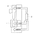
図4に「 センサ信号」の表示で示すように、歪みセンサからの導線は外部に導出され、制御手段50に接続されている。歪みセンサからの信号は制御手段50に入力され、制御手段50はキャビティ内の圧力を検出する。制御手段50が検出した圧力に応じて成形された製品の良不良を判定し、これに応じて射出装置60の運転条件を手動又は自動で制御することができる。また、制御手段50は、成形用金型1に型締信号を送って型締動作を開始させる。そして、成形用金型1が正規の状態で型締された場合には、型締めを確認するフィードバック信号が成形用金型1から制御手段50に送られ、制御手段50はこのフィードバック信号を受けてから樹脂の射出などの成形作業を開始するようにしてもよい。
【0020】
金型装置の基本構成は上記の通りであるが、金型自体及びセンサ(エジェクタピン)の配置位置は実際には次の通りである。即ち、この金型は、従来の制御方法ではショートが発生しやすかった微細部を含むものである。また、実際のセンサの配置位置は、ゲート近傍と、従来の制御方法におけるショート発生箇所近傍である。
ショート発生箇所近傍にセンサを配置した理由は、次の(1)〜(3)である。
【0021】
(1)センサ位置がゲート近傍でもショート箇所近傍でも、あるいはゲート近傍からショート箇所近傍までの充填流路上であれば、圧力は同様に急上昇するので、検知に使用できる。逆に、他の部分例えば最終充填部では、樹脂到達後、すぐに圧力が立ちあがる場合は検知が困難である。
【0022】
(2)ショートする箇所そのものにセンサを組み付けたくても、通常は微細部分になっていて、組み付けられない。
【0023】
(3)加圧による圧力の急上昇は、型内の全体でほぼ同時期に発生する。
【0024】
ゲート近傍にセンサを設けた理由は上記(1)〜(3)に加えさらに、次の(4)〜(6)がある。
【0025】
(4)他の位置より、樹脂が到達した時点での圧力が高く、検知開始時期が正確に検出できる。また、所定圧力に達した時期を基点にすることも容易である。
【0026】
(5)型内で最も長い時間、圧力検知でき、他の型内情報収集にも都合が「よい。
【0027】
(6)正確なショート位置は、成形開始してから判明するもので、型製作段階では予想は困難である。
【0028】
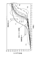
このような金型装置を用いて実際に成形作業を複数回行ない、その結果、図3に示すように複数の良品(圧力波形図P、P1、P2、P3で示す)、不良品(ショート品)についての圧力波形図が得られた。
【0029】
図3からわかるように、各圧力波形は、良品の場合と不良品の場合とで差が小さく緩上昇していく第1の領域R1と、良品の場合が不良品の場合よりも先に立ち上がって急上昇している第2の領域R2と、良品の場合と不良品の場合とで差が小さくピークに向けて緩上昇していく第3の領域R3が連続して構成している曲線である。ここで、「差が小さい」とは、良品と不良品を上記3つの領域においてそれぞれ比較した場合の相対的な評価である。また、「緩上昇」と「急上昇」の語は、3つの領域について圧力波形の時間変化を相対的に比較した場合の評価である。
【0030】
図3に示すように、良品の圧力線と不良品の圧力線が密集しているところでは、両者はかなり接近している。しかし、良品の場合と不良品の場合とでは、良品の方が圧力が大きく、一般に第2の領域での立ち上がりが早いという特徴があることがわかった。例えば領域R2において示すように、圧力線P1、P2、P3は良品であり、これ以外は不良品である。そこで、この特徴を用いて、良品の圧力線とそれ以外(即ち不良品の場合)の圧力線とを確実に識別できるような監視区間を、圧力線図上に設定することとした。
【0031】
まず、第1の領域R1と第2の領域R2に近接して、所定圧力以上の相対的に短い圧力幅であって、相対的に長い時間幅である横に細長い矩形の第1監視区間W1を設定する。成形している製品の金型内の成形圧力が、前記第1監視区間W1の下側の境界線を越えて領域内に入り、上側の境界線面を越えて領域外に出た時に良品と判断し、それ以外の場合に不良品と判断する。
【0032】
また、第2の領域R2と第3の領域R3に近接して、所定圧力以上の相対的に長い圧力幅であって、相対的に短い時間幅である縦に細長い矩形の第2監視区間W2を設定する。成形している製品の金型内の成形圧力が、前記第2監視区間W2の左側の境界線を越えて領域内に入り、右側の境界線を越えて領域外に出た時に良品と判断し、それ以外の場合に不良品と判断する。
【0033】
このような2つの監視区間W1、W2の設定は、成形作業における金型内圧力の立ち上がりに一定の条件を付けるものである。即ち、図3に示した本例の監視区間W1、W2においては、圧力と時間について次のような条件を設定したことを意味する。圧力については、樹脂が型内に充填後、圧力が急上昇しはじめるが、この時の圧力が75kgf/cm2 よりも高く、加圧時の圧力の急上昇が緩やかになる前の圧力が175kgf/cm2 未満であることである。時間については、成形開始後、1.3秒以内に175kgf/cm2 により高圧になることと、成形開始後、1.1秒以内に75fkg/cm2 により高圧になることである。
【0034】
このような2つの監視区間W1、W2の何れかを、それぞれ定められた形で通過した圧力線Pの成形品は良品であることが保証される。図3において、良品と不良品の圧力線が密集しているところでは、良品の一部(例えばP1,P2,P3)がこの2つの監視区間W1、W2にはかからないこととなるが、逆に圧力線がこの監視区間W1、W2に正規の形で交差するように成形作業を制御すれば、ショート不良品ができるおそれは解消できる。
【0035】
図4に示す制御手段50には、前述したような圧力波形の基本データに基づいて予め設定された監視区間W1、W2のデータが格納されている。そして、成形時、成形用金型1の圧力センサ(エジェクタピン24)から送られてくる圧力信号と前記監視区間W1、W2のデータを比較し、現在成形されている製品が良品か不良品かを判定する。具体的には、樹脂の充填開始後の経過時間に対する金型内の成形圧力が、第1及び第2の監視区間W1、W2に対して上述した態様で交差するか否かを比較・判断する。
【0036】
成形作業においてショート不良が出たと制御手段50が判断した場合には、制御手段50は外部にその旨を表示する。作業者は、その表示に対応して不良とされた成形品を選り分け、さらに射出装置60による成形作業の成形条件を変えて、以後ショート不良が発生しないようにする。即ち、不良品が生じたということは、その製品の圧力線が図3において監視区間W1、W2に正規の態様で交差していないことを意味するので、成形条件を変更することにより、図3において圧力線を早く立ち上げて監視区間W1、W2に正規の状態で交差させるようにする。
【0037】
射出装置60の制御は、一般にスクリュの速度か、又はスクリュの駆動によって得られる樹脂の圧力自体の何れかを指標として行なう。本例では、射出装置60の制御は速度優位で制御する。しかし、第1又は第2の監視区間W1、W2の時間を越すまでスクリュの速度によって制御した場合において、圧力線が監視区間W1、W2に対して正規の交差をしなかった場合には、これ以後は圧力を指標として制御し、圧力値を監視区間W1、W2の目標値まで上昇させる。
【0038】
以上説明した例では、成形用金型1のセンサからの信号によって金型内の圧力を検知し、予め設定した監視区間W1、W2との関係が所期の通りにならなかった場合に不良と判定し、この判定に基づいて不良品の排除と成形条件の再設定を手動で行なっていた。
【0039】
しかしながら、成形条件の再設定は制御手段50からの制御信号によって自動的に行なっても良い。具体的には、センサが型内に樹脂圧を検知した時期から、加圧によって圧力が急上昇して所定圧力に達する時期までを、所定時間内で得られるように、充填速度と、充填圧力と、保持圧力と、速度制御−圧力制御切り替え位置を、ショットごとに自動的に制御する。
【0040】
また、2つの監視区間W1、W2を設定した前記例の場合、いずれか1つについて合格すれば良品と判断してもよいし、2つとも合格した場合に良品と判断することとしてもよい。また、設定する監視区間はいすれか1つだけでもよい。
【0041】
【発明の効果】
本発明によれば、所定パターンの圧力時間曲線を有する成形作業において、当該パターンに対応して時間と圧力の監視区間を設けたので、ショート不良品と良品とを確実に識別することができるという効果がある。
【図面の簡単な説明】
【図1】成形用金型の断面図である。
【図2】成形用金型に設けられたセンサ内蔵型エジェクタピンの断面図である。
【図3】成形用金型の成形作業における型内圧力−時間曲線と、本例において設定された監視区間を示す図である。
【図4】本例の金型装置の構成を示す図である。
【図5】従来ショートショットが問題になった成形部品の一例を示す拡大斜視図である。
【図6】(a)はショートショットが発生しない図5の成形部品の部分拡大図、(b)はショートショットが発生した図5の成形部品の部分拡大図である。
【符号の説明】
1…成形用金型、
50…制御手段、
60…射出装置、
R1…第1の領域、
R2…第2の領域、
R3…第3の領域、
W1…第1の監視区間、
W2…第2の監視区間。[0001]
BACKGROUND OF THE INVENTION
In the production of a resin molded product using a mold, there may be a portion in the mold that is not filled with resin, or a portion that is insufficiently filled (referred to as lacking or short shot). a defective product without becoming. The present invention relates to a molding apparatus capable of detecting the occurrence of such a short shot or automatically controlling molding conditions so as to avoid the occurrence of such a short shot.
[0002]
[Prior art]
Short shot refers to the case where there is an unfilled part of the resin in the molded product. In general, the "short end" that occurs in the final filling part on the opposite side of the gate, the fine part between the gate and the final filling part, etc. there is a "fine part short" that occur.
[0003]
Of the two shorts, it is known that the “terminal short” can be detected relatively easily from the peak pressure of the cavity forming the molded product.
[0004]
[Problems to be solved by the invention]
However, in the case of a “fine part short”, the peak pressure cannot be managed alone. There are cases where short-circuiting does not occur even at low pressure, and short-circuiting may occur at high pressure, making detection difficult. For example, FIG. 5 is a perspective view of a resin molded product related to the occurrence of the “fine portion short-circuit”, and the inner surface of the approximately 2 mm square hole portion shown in an enlarged manner in FIG. 6 has a minute side of less than about 0.3 mm on a side. stepped
[0005]
An object of the present invention is to detect a microscopic short-circuit, which has conventionally been difficult to detect, and to control the molding apparatus so that such a defect does not occur.
[0006]
[Means for Solving the Problems]
According to a first aspect of the present invention, there is provided a method for detecting a defective product, wherein when a molded product is formed by filling a mold with a resin, the filling of the resin is detected by a pressure sensor, and the mold with respect to the elapsed time after the start of detection A first region (R1) that slowly rises in a relatively small difference between the case of a non-defective product and a case of a defective product, and a second region (R2) that rises relatively rapidly, Resin filling in the molding process of a molded product that continuously passes through the third region (R3) that gradually rises toward the peak with a relatively small difference between a non-defective product and a defective product. it is a detection method for detecting a defective product for. And the feature is that the first monitoring section (W1) is set close to the first area, the second monitoring section (W2) is set close to the second area, and the first monitoring section is set. A relatively short time width with a relatively short pressure width that is equal to or greater than a predetermined pressure as compared with the second monitoring interval and a relatively long time width as a monitoring interval and a relative pressure that is equal to or greater than the predetermined pressure with respect to the second monitoring interval. A monitoring section with a relatively long pressure width and a relatively short time width is determined to be a non-defective product when the molding pressure in the mold of the product being molded enters from the lower surface of the first monitoring section and escapes from the upper surface. , it is to determine otherwise defective.
[0007]
The method for detecting a defective product according to
[0008]
According to a third aspect of the present invention, there is provided a defective product detection apparatus in which when a molded product is formed by filling a mold with a resin, the filling of the resin is detected by a pressure sensor, and the mold with respect to an elapsed time after the start of detection. A first region (R1) that slowly rises in a relatively small difference between the case of a non-defective product and a case of a defective product, and a second region (R2) that rises relatively rapidly, Resin filling in the molding process of a molded product that continuously passes through the third region (R3) that gradually rises toward the peak with a relatively small difference between a non-defective product and a defective product. a detector for detecting defective for. And the feature is that the first monitoring section (W1) is set close to the first area, the second monitoring section (W2) is set close to the second area, and the first monitoring section is set. A relatively short time width with a relatively short pressure width that is equal to or greater than a predetermined pressure as compared with the second monitoring interval and a relatively long time width as a monitoring interval and a relative pressure that is equal to or greater than the predetermined pressure with respect to the second monitoring interval. A monitoring section with a relatively long pressure width and a relatively short time width is determined to be a non-defective product when the molding pressure in the mold of the product being molded enters from the lower surface of the first monitoring section and escapes from the upper surface. In other cases, a control unit for determining a defective product is provided.
[0009]
According to a fourth aspect of the present invention, there is provided a defective product detection apparatus in which when a molded product is formed by filling a mold with a resin, the filling of the resin is detected by a pressure sensor, and the mold with respect to an elapsed time after the start of detection is detected. A first region (R1) that slowly rises in a relatively small difference between the case of a non-defective product and a case of a defective product, and a second region (R2) that rises relatively rapidly, In the molding process of the molded product, the third region (R3), which gradually rises toward the peak with a relatively small difference between the non-defective product and the defective product, has a continuous curve. a detector for detecting defective. Then, the feature sets the second monitoring section proximate to the second region (W2) sets the close proximity to the first monitoring period (W1) in the first region, the first monitoring interval A relatively short time width with a relatively short pressure width that is equal to or greater than a predetermined pressure as compared with the second monitoring interval and a relatively long time width as a monitoring interval and a relative pressure that is equal to or greater than the predetermined pressure with respect to the second monitoring interval. and monitored section of relatively short duration with a long pressure width, the good when the molding pressure in the mold of the product being molded, exited from the frame side enters from the frame side of the second monitor block It is to have a control unit that makes a judgment and judges that it is a defective product in other cases.
[0010]
A molding apparatus according to claim 5 is an injection apparatus that injects a resin, and a mold that includes a pressure sensor that detects a pressure of an internal resin while forming a molded product by supplying the resin from the injection apparatus. When, and a control unit. And the control part controls the control conditions of the said injection apparatus as follows. That is, the resin filling is started by the pressure sensor, and the molding pressure in the mold with respect to the elapsed time after the start of detection gradually rises with a relatively small difference between the non-defective product and the defective product. The region (R1), the second region (R2) that has risen relatively rapidly, and the third region that gradually rises toward the peak with a relatively small difference between the non-defective product and the defective product. In the molding process of a molded product that has a continuous curve with the region (R3), a first monitoring section is set close to the first region and a second monitoring section is set close to the second region. The first monitoring section is a monitoring section having a relatively short time width and a relatively long time width compared to the second monitoring section, and the second monitoring section is the first monitoring section. A relatively short time with a relatively long pressure range above a specified pressure Of the monitoring period, the molding pressure in the mold of the product being molded, to control the control condition of the injection apparatus as exit from the top surface enters from the lower surface of the first monitoring period.
[0011]
A molding apparatus according to claim 6 is an injection apparatus that injects a resin, and a mold that includes a pressure sensor that detects a pressure of an internal resin while forming a molded product by supplying the resin from the injection apparatus. When, and a control unit. And the control part controls the control conditions of the said injection apparatus as follows. That is, the resin filling is started by the pressure sensor, and the molding pressure in the mold with respect to the elapsed time after the start of detection gradually rises with a relatively small difference between the non-defective product and the defective product. Area (R1), a second area (R2) that rises relatively rapidly, and a third area that rises slowly toward the peak in a relatively small difference between a non-defective product and a defective product (R3) In the molding process of the molded product, which is a continuous curve,
A first monitoring section is set close to the first area and a second monitoring section is set close to the second area, and the first monitoring section is equal to or higher than a predetermined pressure compared to the second monitoring section. A relatively short time width with a relatively short pressure width and a relatively long time width, and the second monitoring section with a relatively long pressure width equal to or greater than a predetermined pressure compared to the first monitoring section. The molding pressure in the mold of the product being molded is controlled so as to enter from the side of the frame of the second monitoring zone and escape from the side of the frame.
[0012]
DETAILED DESCRIPTION OF THE INVENTION
1 and 2 are sectional views showing a basic structure of a molding die having an ejector pin with a sensor as pressure detecting means. The present inventors diligently studied the occurrence of the above-mentioned “fine part short” using this molding die. In addition, when the control means to be described later is combined with this molding die, the mold apparatus of the present invention is obtained, and the occurrence of short defective products can be detected during molding, and the molding operation is controlled so that no short defective products are generated. Can do.
[0013]
The molding die 1 includes a fixed
[0014]
The molding die B can be divided between the fixed side mold plate 12 and the movable
[0015]
The fixed-
[0016]
An
[0017]
As shown in FIG. 2, the
[0018]
In the
In this example, an apparatus using an ejector pin and a strain sensor is used as the pressure sensor, but it is not necessary to be limited to this as long as the pressure in the mold can be detected. Further, the position to be provided may be either the fixed side or the movable side of the mold apparatus, or may be provided on the slide core.
[0019]
As shown by the display of “sensor signal” in FIG. 4, the lead wire from the strain sensor is led out to the outside and connected to the control means 50. A signal from the strain sensor is input to the control means 50, and the control means 50 detects the pressure in the cavity. The quality of the molded product can be determined according to the pressure detected by the control means 50, and the operating conditions of the
[0020]
The basic configuration of the mold apparatus is as described above, but the arrangement positions of the mold itself and the sensor (ejector pin) are actually as follows. In other words, this mold includes a fine part that is easily short-circuited by the conventional control method. Further, the actual sensor placement positions are near the gate and near the location where a short circuit occurs in the conventional control method.
The reason why the sensor is arranged in the vicinity of the short occurrence location is the following (1) to (3).
[0021]
(1) If the sensor position is in the vicinity of the gate or in the vicinity of the short circuit, or on the filling flow path from the vicinity of the gate to the vicinity of the short circuit, the pressure rises rapidly and can be used for detection. On the other hand, in other parts, for example, the final filling part, it is difficult to detect when pressure rises immediately after reaching the resin.
[0022]
(2) Even if it is desired to assemble the sensor at the shorted location itself, it is usually a fine part and cannot be assembled.
[0023]
(3) The sudden increase in pressure due to pressurization occurs almost simultaneously in the entire mold.
[0024]
The reason why the sensor is provided in the vicinity of the gate includes the following (4) to (6) in addition to the above (1) to (3).
[0025]
(4) The pressure when the resin arrives is higher than the other positions, and the detection start time can be accurately detected. It is also easy to use the time when the predetermined pressure is reached as a base point.
[0026]
(5) The pressure can be detected for the longest time in the mold, which is convenient for collecting information in other molds.
[0027]
(6) The exact short position is known after the start of molding, and is difficult to predict at the mold production stage.
[0028]
As shown in FIG. 3, a plurality of non-defective products (indicated by pressure waveform diagrams P, P1, P2, and P3) and defective products (short products) are actually formed multiple times using such a mold apparatus. ) Was obtained.
[0029]
As can be seen from FIG. 3, each pressure waveform rises before the first region R <b> 1 where the difference between the non-defective product and the defective product is small and rises slowly, and the non-defective product is earlier than the defective product. The second region R2 rising rapidly and the third region R3 gradually increasing toward the peak with a small difference between the non-defective product and the defective product are continuously formed. . Here, “small difference” is a relative evaluation when a non-defective product and a defective product are compared in the above three regions. Further, the words “slow rise” and “sudden rise” are evaluations in the case where the time changes of the pressure waveforms are relatively compared for the three regions.
[0030]
As shown in FIG. 3, where the pressure lines for good products and the pressure lines for defective products are densely packed, the two are quite close to each other. However, it was found that the non-defective product and the non-defective product are characterized in that the non-defective product has a higher pressure and generally rises quickly in the second region. For example, as shown in the region R2, the pressure lines P1, P2, and P3 are non-defective products, and the others are defective products. Therefore, by using this feature, a monitoring section is set on the pressure diagram so that the non-defective pressure line and the other (that is, defective) pressure lines can be reliably identified.
[0031]
First, in the vicinity of the first region R1 and the second region R2, a first monitoring section W1 that is a rectangular shape that is a relatively short pressure width that is equal to or greater than a predetermined pressure and that is a relatively long time width. Set. When the molding pressure in the mold of the molded product enters the region beyond the lower boundary line of the first monitoring section W1 and goes out of the region beyond the upper boundary surface, Judgment, otherwise it is judged as a defective product.
[0032]
Further, in the vicinity of the second region R2 and the third region R3, a vertically elongated rectangular second monitoring section W2 having a relatively long pressure width equal to or higher than a predetermined pressure and a relatively short time width. Set. When the molding pressure in the mold of the molded product enters the region beyond the left boundary line of the second monitoring section W2, and is determined to be non-defective when it exceeds the right boundary line and goes out of the region. In other cases, it is judged as a defective product.
[0033]
Such setting of the two monitoring sections W1 and W2 places a certain condition on the rise of the pressure inside the mold in the molding operation. That is, in the monitoring sections W1 and W2 of this example shown in FIG. 3, it means that the following conditions are set for pressure and time. As for the pressure, after the resin is filled in the mold, the pressure starts to rise rapidly, but the pressure at this time is higher than 75 kgf / cm 2 , and the pressure before the pressure suddenly rises slowly is 175 kgf /
[0034]
It is guaranteed that the molded product of the pressure line P that has passed through one of the two monitoring sections W1 and W2 in a predetermined shape is a non-defective product. In FIG. 3, where the non-defective product and defective product pressure lines are concentrated, a part of the good product (for example, P1, P2, P3) does not cover these two monitoring sections W1, W2. If the molding operation is controlled so that the pressure line intersects the monitoring sections W1 and W2 in a regular manner, the possibility of a defective short circuit can be eliminated.
[0035]
The control means 50 shown in FIG. 4 stores data of the monitoring sections W1 and W2 set in advance based on the basic data of the pressure waveform as described above. Then, at the time of molding, the pressure signal sent from the pressure sensor (ejector pin 24) of the molding die 1 is compared with the data in the monitoring sections W1 and W2, and whether the currently molded product is a good product or a defective product. Determine. Specifically, it is compared and determined whether or not the molding pressure in the mold with respect to the elapsed time after the start of resin filling intersects the first and second monitoring sections W1 and W2 in the manner described above. .
[0036]
When the control means 50 determines that a short circuit failure has occurred in the molding operation, the control means 50 displays the fact to the outside. The operator selects a molded product determined to be defective in accordance with the display, and further changes the molding conditions of the molding operation by the
[0037]
The
[0038]
In the example described above, the pressure in the mold is detected by a signal from the sensor of the molding mold 1 and the relationship with the preset monitoring sections W1 and W2 is not as expected. Based on this determination, rejection of defective products and resetting of molding conditions were manually performed.
[0039]
However, the molding conditions may be reset automatically by a control signal from the control means 50. Specifically, the filling speed, the filling pressure, and the time between the time when the sensor detects the resin pressure in the mold and the time when the pressure suddenly increases due to pressurization and reaches the predetermined pressure are obtained within a predetermined time. The holding pressure and the speed control-pressure control switching position are automatically controlled for each shot.
[0040]
Further, in the case of the above example in which two monitoring sections W1 and W2 are set, it may be determined that the product is non-defective if either one is passed, or may be determined to be non-defective if both are passed. Also, only one monitoring section may be set.
[0041]
【The invention's effect】
According to the present invention, in the molding operation having the pressure time curve of the predetermined pattern, the time and pressure monitoring sections are provided corresponding to the pattern, so that it is possible to reliably identify the short defective product and the non-defective product. effective.
[Brief description of the drawings]
FIG. 1 is a cross-sectional view of a molding die.
FIG. 2 is a cross-sectional view of a sensor built-in type ejector pin provided in a molding die.
FIG. 3 is a diagram showing an in-mold pressure-time curve in a molding operation of a molding die and a monitoring section set in this example.
FIG. 4 is a diagram showing a configuration of a mold apparatus of this example.
FIG. 5 is an enlarged perspective view showing an example of a molded part in which conventional short shots have become a problem.
6A is a partially enlarged view of the molded part of FIG. 5 in which a short shot does not occur, and FIG. 6B is a partially enlarged view of the molded part of FIG. 5 in which a short shot has occurred.
[Explanation of symbols]
1 ... Mold for molding,
50. Control means,
60 ... injection device,
R1 ... first region,
R2 ... second region,
R3 ... third region,
W1 ... first monitoring section,
W2 ... Second monitoring section.
Claims (6)
第1の領域に近接して第1監視区間を設定するとともに第2の領域に近接して第2監視区間を設定し、前記第1監視区間を前記第2監視区間に比べて所定圧力以上の相対的に短い圧力幅で相対的に長い時間幅の監視区間とするとともに前記第2監視区間を前記第1監視区間に比べて所定圧力以上の相対的に長い圧力幅で相対的に短い時間幅の監視区間とし、
成形している製品の金型内の成形圧力が、前記第1監視区間の下面から入って上面から抜けた時に良品と判断し、それ以外の場合に不良品と判断することを特徴とする不良品の検出方法。When molding a molded product by filling the resin into the mold, the pressure sensor detects the resin filling, and the molding pressure in the mold with respect to the elapsed time after the start of detection is good or defective. The first region that slowly rises in a state where the difference is relatively small, the second region that rises relatively rapidly, and a peak in a state where the difference is relatively small between a non-defective product and a defective product In a molding process of a molded product that continuously passes through a third region that gradually rises toward the detection method, a detection method that detects a defective product with respect to resin filling,
A first monitoring section is set close to the first area and a second monitoring section is set close to the second area, and the first monitoring section is equal to or higher than a predetermined pressure compared to the second monitoring section . A relatively short time width with a relatively short pressure width and a relatively long time width, and the second monitoring section with a relatively long pressure width equal to or greater than a predetermined pressure compared to the first monitoring section. Monitoring section,
A non-defective product is characterized in that when the molding pressure in the mold of the molded product enters from the lower surface of the first monitoring section and comes out of the upper surface, it is judged as a non-defective product, and otherwise it is judged as a defective product. Non-defective product detection method.
第1の領域に近接して第1監視区間を設定するとともに第2の領域に近接して第2監視区間を設定し、前記第1監視区間を前記第2監視区間に比べて所定圧力以上の相対的に短い圧力幅で相対的に長い時間幅の監視区間とするとともに前記第2監視区間を前記第1監視区間に比べて所定圧力以上の相対的に長い圧力幅で相対的に短い時間幅の監視区間とし、
成形している製品の金型内の成形圧力が、前記第2監視区間の枠側面から入って枠側面から抜けた時に良品と判断し、それ以外の場合に不良品と判断することを特徴とする不良品の検出方法。When molding a molded product by filling the resin into the mold, the pressure sensor detects the resin filling, and the molding pressure in the mold with respect to the elapsed time after the start of detection is good or defective. The first region that slowly rises in a state where the difference is relatively small, the second region that rises relatively rapidly, and a peak in a state where the difference is relatively small between a non-defective product and a defective product In a molding process of a molded product that continuously passes through a third region that gradually rises toward the detection method, a detection method that detects a defective product with respect to resin filling,
Sets a first monitoring section proximate the first region proximate to the second region and set the second monitoring interval, the predetermined pressure or more than the first monitoring period to the second monitor block A relatively short time width with a relatively short pressure width and a relatively long time width, and the second monitoring section with a relatively long pressure width equal to or greater than a predetermined pressure compared to the first monitoring section. Monitoring section ,
The molding pressure in the mold of the product being molded is determined to be non-defective when entering from the side of the frame of the second monitoring section and coming out of the side of the frame, and otherwise determined to be defective. a method of detecting defective products.
第1の領域に近接して第1監視区間を設定するとともに第2の領域に近接して第2監視区間を設定し、前記第1監視区間を前記第2監視区間に比べて所定圧力以上の相対的に短い圧力幅で相対的に長い時間幅の監視区間とするとともに前記第2監視区間を前記第1監視区間に比べて所定圧力以上の相対的に長い圧力幅で相対的に短い時間幅の監視区間とし、
成形している製品の金型内の成形圧力が、前記第1監視区間の下面から入って上面から抜けた時に良品と判断し、それ以外の場合に不良品と判断する制御部を備えたことを特徴とする不良品の検出装置。When molding a molded product by filling the resin into the mold, the pressure sensor detects the resin filling, and the molding pressure in the mold with respect to the elapsed time after the start of detection is good or defective. The first region that slowly rises in a state where the difference is relatively small, the second region that rises relatively rapidly, and a peak in a state where the difference is relatively small between a non-defective product and a defective product In a molding process of a molded product that continuously passes through the third region that gradually rises toward the detection device, a detection device that detects a defective product with respect to resin filling,
A first monitoring section is set close to the first area and a second monitoring section is set close to the second area, and the first monitoring section is equal to or higher than a predetermined pressure compared to the second monitoring section . A relatively short time width with a relatively short pressure width and a relatively long time width, and the second monitoring section with a relatively long pressure width equal to or greater than a predetermined pressure compared to the first monitoring section. Monitoring section,
A control unit is provided that determines that the molding pressure in the mold of the product being molded enters the lower surface of the first monitoring section and exits from the upper surface, and determines that it is a non-defective product in other cases. defective detection apparatus according to claim.
第1の領域に近接して第1監視区間を設定するとともに第2の領域に近接して第2監視区間を設定し、前記第1監視区間を前記第2監視区間に比べて所定圧力以上の相対的に短い圧力幅で相対的に長い時間幅の監視区間とするとともに前記第2監視区間を前記第1監視区間に比べて所定圧力以上の相対的に長い圧力幅で相対的に短い時間幅の監視区間とし、
成形している製品の金型内の成形圧力が、前記第2監視区間の枠側面から入って枠側面から抜けた時に良品と判断し、それ以外の場合に不良品と判断する制御部を有することを特徴とする不良品の検出装置。When molding a molded product by filling the resin into the mold, the pressure sensor detects the resin filling, and the molding pressure in the mold with respect to the elapsed time after the start of detection is good or defective. The first region that slowly rises in a state where the difference is relatively small, the second region that rises relatively rapidly, and a peak in a state where the difference is relatively small between a non-defective product and a defective product In a detection device for detecting defective products for resin filling in the molding process of a molded product that rubs a continuous curve with a third region that gradually rises toward the
Sets a first monitoring section proximate the first region proximate to the second region and set the second monitoring interval, the predetermined pressure or more than the first monitoring period to the second monitor block A relatively short time width with a relatively short pressure width and a relatively long time width, and the second monitoring section with a relatively long pressure width equal to or greater than a predetermined pressure compared to the first monitoring section. and the monitoring section,
It has a control unit that judges that the molding pressure in the mold of the product being molded enters the side surface of the frame in the second monitoring section and then comes out of the side surface of the frame, and determines that it is defective in other cases. detection device of defective products, characterized in that.
前記射出装置から樹脂を供給されて成形品を成形するとともに、内部の樹脂の圧力を検出する圧力センサを備えた金型と、
圧力センサによって樹脂の充填が検知され、検知開始後の経過時間に対する金型内の成形圧力が、良品の場合と不良品の場合とで相対的に差が小さい状態で緩上昇する第1の領域と、相対的に急上昇する第2の領域と、良品の場合と不良品の場合とで相対的に差が小さい状態でピークに向けて緩上昇する第3の領域とが連続した曲線をえがく成形品の成形工程において、
第1の領域に近接して第1監視区間を設定するとともに第2の領域に近接して第2監視区間を設定し、前記第1監視区間を前記第2監視区間に比べて所定圧力以上の相対的に短い圧力幅で相対的に長い時間幅の監視区間とするとともに前記第2監視区間を前記第1監視区間に比べて所定圧力以上の相対的に長い圧力幅で相対的に短い時間幅の監視区間とし、成形している製品の金型内の成形圧力が、前記第1監視区間の下面から入って上面から抜けるように前記射出装置の制御条件を制御する制御部と、
を有する成形装置。An injection device for injecting resin,
A mold provided with a pressure sensor for detecting the pressure of the internal resin, while molding a molded product supplied with resin from the injection device,
A first region in which resin filling is detected by the pressure sensor, and the molding pressure in the mold with respect to the elapsed time after the start of detection gradually rises with a relatively small difference between a non-defective product and a defective product. And a second region that rises relatively rapidly and a third region that gradually rises toward the peak with a relatively small difference between a non-defective product and a defective product. In the product molding process,
A first monitoring section is set close to the first area and a second monitoring section is set close to the second area, and the first monitoring section is equal to or higher than a predetermined pressure compared to the second monitoring section. A relatively short time width with a relatively short pressure width and a relatively long time width, and the second monitoring section with a relatively long pressure width equal to or greater than a predetermined pressure compared to the first monitoring section. A control section that controls the control conditions of the injection device so that the molding pressure in the mold of the product being molded enters from the lower surface of the first monitoring section and exits from the upper surface,
A molding apparatus having:
前記射出装置から樹脂を供給されて成形品を成形するとともに、内部の樹脂の圧力を検出する圧力センサを備えた金型と、
圧力センサによって樹脂の充填が検知され、検知開始後の経過時間に対する金型内の成形圧力が、良品の場合と不良品の場合とで相対的に差が小さい状態で緩上昇する第1の領域と、相対的に急上昇する第2の領域と、良品の場合と不良品の場合とで相対的に差が小さい状態でピークに向けて緩上昇する第3の領域とが連続した曲線をえがく成形品の成形工程において、
第1の領域に近接して第1監視区間を設定するとともに第2の領域に近接して第2監視区間を設定し、前記第1監視区間を前記第2監視区間に比べて所定圧力以上の相対的に短い圧力幅で相対的に長い時間幅の監視区間とするとともに前記第2監視区間を前記第1監視区間に比べて所定圧力以上の相対的に長い圧力幅で相対的に短い時間幅の監視区間とし、成形している製品の金型内の成形圧力が、前記第2監視区間の枠側面から入って枠側面から抜けるように前記射出装置の制御条件を制御する制御部と、
を有する成形装置。An injection device for injecting resin,
A mold provided with a pressure sensor for detecting the pressure of the internal resin, while molding a molded product supplied with resin from the injection device,
A first region in which resin filling is detected by the pressure sensor, and the molding pressure in the mold with respect to the elapsed time after the start of detection gradually rises with a relatively small difference between a non-defective product and a defective product. And a second region that rises relatively rapidly and a third region that gradually rises toward the peak with a relatively small difference between a non-defective product and a defective product. In the product molding process,
A first monitoring section is set close to the first area and a second monitoring section is set close to the second area, and the first monitoring section is equal to or higher than a predetermined pressure compared to the second monitoring section. A relatively short time width with a relatively short pressure width and a relatively long time width, and the second monitoring section with a relatively long pressure width equal to or greater than a predetermined pressure compared to the first monitoring section. A control section that controls the control conditions of the injection device so that the molding pressure in the mold of the product being molded enters from the side of the frame of the second monitoring section and exits from the side of the frame;
A molding apparatus having:
Priority Applications (1)
| Application Number | Priority Date | Filing Date | Title |
|---|---|---|---|
| JP2000276787A JP4635309B2 (en) | 2000-09-12 | 2000-09-12 | Defective product detection method and apparatus, and molding apparatus. |
Applications Claiming Priority (1)
| Application Number | Priority Date | Filing Date | Title |
|---|---|---|---|
| JP2000276787A JP4635309B2 (en) | 2000-09-12 | 2000-09-12 | Defective product detection method and apparatus, and molding apparatus. |
Publications (2)
| Publication Number | Publication Date |
|---|---|
| JP2002086500A JP2002086500A (en) | 2002-03-26 |
| JP4635309B2 true JP4635309B2 (en) | 2011-02-23 |
Family
ID=18762205
Family Applications (1)
| Application Number | Title | Priority Date | Filing Date |
|---|---|---|---|
| JP2000276787A Expired - Fee Related JP4635309B2 (en) | 2000-09-12 | 2000-09-12 | Defective product detection method and apparatus, and molding apparatus. |
Country Status (1)
| Country | Link |
|---|---|
| JP (1) | JP4635309B2 (en) |
Families Citing this family (6)
| Publication number | Priority date | Publication date | Assignee | Title |
|---|---|---|---|---|
| KR101119949B1 (en) * | 2009-04-13 | 2012-03-15 | 아주대학교산학협력단 | Method for determining time of arrival of resin flow in mold |
| JP6913467B2 (en) * | 2017-01-17 | 2021-08-04 | エムテックスマツムラ株式会社 | Resin molding mold and resin molding equipment |
| JP7293962B2 (en) * | 2019-08-08 | 2023-06-20 | 株式会社ジェイテクト | Molded product quality anomaly prediction system |
| JP7349869B2 (en) * | 2019-10-02 | 2023-09-25 | ミネベアミツミ株式会社 | Pressure detection device and pass/fail judgment method |
| JP7349868B2 (en) * | 2019-10-02 | 2023-09-25 | ミネベアミツミ株式会社 | Pressure detection device and pass/fail judgment method |
| JPWO2024176461A1 (en) * | 2023-02-24 | 2024-08-29 |
Family Cites Families (6)
| Publication number | Priority date | Publication date | Assignee | Title |
|---|---|---|---|---|
| JPS55161628A (en) * | 1979-06-04 | 1980-12-16 | Hitachi Ltd | Injection molding method |
| JPS5651339A (en) * | 1979-10-03 | 1981-05-08 | Hitachi Ltd | Method and apparatus for injection molding of synthetic resin |
| JP2586943B2 (en) * | 1988-05-17 | 1997-03-05 | ファナック株式会社 | Inspection machine for injection molding machine |
| JP2628384B2 (en) * | 1989-11-14 | 1997-07-09 | ファナック株式会社 | Product quality judgment method for injection molding machines |
| JPH0749213B2 (en) * | 1990-11-07 | 1995-05-31 | 松下電器産業株式会社 | Method of distinguishing molded products from injection molding machines |
| JPH07232366A (en) * | 1994-02-24 | 1995-09-05 | Sony Corp | Injection molding determination method and apparatus |
-
2000
- 2000-09-12 JP JP2000276787A patent/JP4635309B2/en not_active Expired - Fee Related
Also Published As
| Publication number | Publication date |
|---|---|
| JP2002086500A (en) | 2002-03-26 |
Similar Documents
| Publication | Publication Date | Title |
|---|---|---|
| US6379141B1 (en) | Abnormal mold detector | |
| JP4635309B2 (en) | Defective product detection method and apparatus, and molding apparatus. | |
| JP2009137076A (en) | Injection mold, method for detecting plasticization failure in injection molding, and injection molding method | |
| JP3045078B2 (en) | Ejector pin with pressure sensor | |
| CN106938520A (en) | A kind of high intelligent die | |
| TW426599B (en) | Injection compressing forming method and injection compressing forming device for performing the method | |
| WO2005070592A1 (en) | Casting machine | |
| WO2005070593A1 (en) | Thermosensor for casting machine and casting machine | |
| JP6913467B2 (en) | Resin molding mold and resin molding equipment | |
| JP2019181921A (en) | Injection molding device and injection molding method | |
| JP5755627B2 (en) | Nozzle touch method and touch device for injection molding machine | |
| JP2021008067A (en) | Mold clamping device and mold clamping force adjustment method | |
| JP2020146942A (en) | Injection molding method and injection molding machine | |
| JP2008114286A (en) | Molten metal filling condition-determining apparatus in die casting machine, and molten metal filling condition good/bad judging method | |
| JPH09117938A (en) | Structure for confirming resin filling degree in injection mold | |
| JPH09327849A (en) | Injection compression molding monitor display method | |
| JP2704422B2 (en) | Judgment method of molded products in injection molding equipment | |
| JP3503257B2 (en) | Injection speed control method for die casting | |
| JP2587575B2 (en) | Injection molding method and injection molding machine | |
| JP2002307155A (en) | Metal injection mold | |
| US20060110489A1 (en) | Apparatus for measuring separation of mold parts | |
| JP2633738B2 (en) | Resin leakage detection method for injection molding machines | |
| JP2004330479A (en) | Monitor display method for displaying molding state of injection molding device | |
| KR20260004937A (en) | Injection molding machine and setting method for ejector movable range of the same | |
| JPS61182920A (en) | Quality judging device of molded article in injection molding machine |
Legal Events
| Date | Code | Title | Description |
|---|---|---|---|
| A621 | Written request for application examination |
Free format text: JAPANESE INTERMEDIATE CODE: A621 Effective date: 20070912 |
|
| A977 | Report on retrieval |
Free format text: JAPANESE INTERMEDIATE CODE: A971007 Effective date: 20100309 |
|
| A131 | Notification of reasons for refusal |
Free format text: JAPANESE INTERMEDIATE CODE: A131 Effective date: 20100413 |
|
| A521 | Request for written amendment filed |
Free format text: JAPANESE INTERMEDIATE CODE: A523 Effective date: 20100610 |
|
| TRDD | Decision of grant or rejection written | ||
| A01 | Written decision to grant a patent or to grant a registration (utility model) |
Free format text: JAPANESE INTERMEDIATE CODE: A01 Effective date: 20101026 |
|
| A01 | Written decision to grant a patent or to grant a registration (utility model) |
Free format text: JAPANESE INTERMEDIATE CODE: A01 |
|
| A61 | First payment of annual fees (during grant procedure) |
Free format text: JAPANESE INTERMEDIATE CODE: A61 Effective date: 20101108 |
|
| FPAY | Renewal fee payment (event date is renewal date of database) |
Free format text: PAYMENT UNTIL: 20131203 Year of fee payment: 3 |
|
| R150 | Certificate of patent or registration of utility model |
Free format text: JAPANESE INTERMEDIATE CODE: R150 Ref document number: 4635309 Country of ref document: JP Free format text: JAPANESE INTERMEDIATE CODE: R150 |
|
| R250 | Receipt of annual fees |
Free format text: JAPANESE INTERMEDIATE CODE: R250 |
|
| R250 | Receipt of annual fees |
Free format text: JAPANESE INTERMEDIATE CODE: R250 |
|
| R250 | Receipt of annual fees |
Free format text: JAPANESE INTERMEDIATE CODE: R250 |
|
| R250 | Receipt of annual fees |
Free format text: JAPANESE INTERMEDIATE CODE: R250 |
|
| LAPS | Cancellation because of no payment of annual fees |