JP4635283B2 - Nonaqueous electrolyte secondary battery - Google Patents
Nonaqueous electrolyte secondary battery Download PDFInfo
- Publication number
- JP4635283B2 JP4635283B2 JP28130999A JP28130999A JP4635283B2 JP 4635283 B2 JP4635283 B2 JP 4635283B2 JP 28130999 A JP28130999 A JP 28130999A JP 28130999 A JP28130999 A JP 28130999A JP 4635283 B2 JP4635283 B2 JP 4635283B2
- Authority
- JP
- Japan
- Prior art keywords
- negative electrode
- solid phase
- alloy
- tin
- zinc
- Prior art date
- Legal status (The legal status is an assumption and is not a legal conclusion. Google has not performed a legal analysis and makes no representation as to the accuracy of the status listed.)
- Expired - Lifetime
Links
Images
Classifications
-
- Y—GENERAL TAGGING OF NEW TECHNOLOGICAL DEVELOPMENTS; GENERAL TAGGING OF CROSS-SECTIONAL TECHNOLOGIES SPANNING OVER SEVERAL SECTIONS OF THE IPC; TECHNICAL SUBJECTS COVERED BY FORMER USPC CROSS-REFERENCE ART COLLECTIONS [XRACs] AND DIGESTS
- Y02—TECHNOLOGIES OR APPLICATIONS FOR MITIGATION OR ADAPTATION AGAINST CLIMATE CHANGE
- Y02E—REDUCTION OF GREENHOUSE GAS [GHG] EMISSIONS, RELATED TO ENERGY GENERATION, TRANSMISSION OR DISTRIBUTION
- Y02E60/00—Enabling technologies; Technologies with a potential or indirect contribution to GHG emissions mitigation
- Y02E60/10—Energy storage using batteries
Landscapes
- Secondary Cells (AREA)
- Battery Electrode And Active Subsutance (AREA)
- Powder Metallurgy (AREA)
Description
【0001】
【発明の属する技術分野】
本発明は、非水電解質二次電池、特にその負極材料に関するものである。
【0002】
【従来の技術】
近年、移動体通信機器、携帯電子機器の主電源として利用されているリチウム二次電池は、起電力が高く、高エネルギー密度である特長を有している。負極材料としてリチウム金属を用いたリチウム二次電池は、エネルギー密度は高いが、充電時に負極にデンドライトが析出し、充放電を繰り返すことによりセパレータを突き破って正極側に達し、内部短絡を起こす恐れがあった。また、析出したデンドライトは比表面積が大きいため反応活性度が高く、その表面で電解液中の溶媒と反応して電子伝導性に欠いた固体電解質的な界面皮膜を形成する。そのため電池の内部抵抗が高くなったり、電子伝導のネットワークから孤立した粒子が存在するようになり、これらが充放電効率を低下させる要因となっている。これらの理由で負極材料としてリチウム金属を用いたリチウム二次電池は、低い信頼性、および短いサイクル寿命に問題があった。
【0003】
現在、リチウム金属に替わる負極材料として、リチウムイオンを吸蔵・放出できる炭素材料を使用し実用化に至っている。通常、炭素材料負極には金属リチウムは析出しないため、デンドライトによる内部短絡の問題はない。しかし、炭素材料の一つである黒鉛の理論容量は372mAh/gであり、Li金属単体の理論容量の10分の1程度と少ない。
【0004】
他の負極材料として、リチウムと化合物を形成する単体金属材料および単体非金属材料が知られている。例えば、ケイ素(Si)(米国特許3,969,139号)、スズ(Sn)(米国特許4,436,796号)、亜鉛(Zn)のリチウムを最も含む化合物の組成式は、それぞれLi22Si5、Li22Sn5、LiZnであり、この範囲では金属リチウムは通常析出しないため、デンドライトによる内部短絡の問題はない。そして、これら化合物と各単体材料との間の電気化学容量は、それぞれ4199mAh/g、993mAh/g、410mAh/gであり、いずれも黒鉛の理論容量よりも大きい。
【0005】
またリチウムと化合物を形成する単体金属材料および単体非金属材料の他に化合物負極材料として、特開平4−126371号公報、特開平7−29602号公報、特開平7−240201号公報、特開平8−153517号公報に遷移元素などからなる金属間化合物が、特開平9−63651号公報には4B族元素及びP、Sbの少なくとも一つを含む金属間化合物からなり、その結晶構造がCaF2型、ZnS型、AlLiSi型のいずれかからなる負極材料などが提案されている。このほか、特開平10−294112号公報に超急冷の金属硅化物を負極材料として用いることが提案され、さらに特開平11−86853号公報に金属間化合物相を含みかつこの金属間化合物に含まれる元素で構成される上記金属間化合物以外の相を1相以上含む粒子を用いることなどが提案されている。
【0006】
【発明が解決しようとする課題】
しかしながら、上記のような炭素材料よりも高容量の負極材料には、それぞれ以下に示すような課題がある。
【0007】
リチウムと化合物を形成する単体金属材料および単体非金属材料の負極材料は共通して、炭素負極材料にくらべて充放電サイクル特性が悪い。その理由は充電時と放電時のリチウムの吸蔵・放出に伴う体積差が大きくなるため、材料に大きな歪みや亀裂が生じ、粒子が微細化すると考えられている。さらにこの微細化した粒子間に空間が生じ、電子伝導ネットワークが分断され、電気化学的な反応に関与できない部分が増加し、充放電容量が低下すると考えられる。
【0008】
すなわちリチウムと化合物を形成する単体金属材料および単体非金属材料の負極材料に共通する大きな体積変化と、これによる組織変化が、炭素負極材料に比べて充放電サイクル特性を悪化させる要因であると推察される。
【0009】
一方、上述の単体材料と異なり、遷移元素からなる非鉄金属の珪化物や4B族元素及びP、Sbの少なくとも一つを含む金属間化合物からなり、その結晶構造がCaF2型、ZnS型、AlLiSi型のいずれかからなる負極材料などは、サイクル寿命特性の改善された負極材料としてそれぞれ特開平7−240201号公報、特開平9−63651号公報に提案されている。
【0010】
特開平7−240201号公報に示された遷移元素からなる非鉄金属の珪化物負極材料を用いた電池は、リチウム金属負極材料と比較して充放電サイクル特性は改善されるが、天然黒鉛負極材料と比較して容量は最大でも12%程度しか増加していない。よって、遷移元素からなる非鉄金属の珪化物負極材料は黒鉛負極材料に比べて大幅な容量増加は期待されない。
【0011】
また、特開平9−63651号公報に示された材料は、Li−Pb合金負極材料よりも充放電サイクル特性が改善されており、かつ黒鉛負極材料よりも高容量であることが示されている。しかし、10〜20サイクルまでの充放電サイクルで放電容量の減少が著しく、最も良好と思われるMg2Snにおいても約20サイクル後には初期容量の70%程度に減少している。単体材料とその金属間化合物を備えた、たとえば特開平4−126371号公報や特開平7−29602号公報記載の材料は確かに単体で用いるよりも金属間化合物や合金などの作用により構造の維持が可能になりサイクル特性の改善がみられるが、単体材料自身が電解液と直接反応する界面が存在するためこの部分での金属間化合物や合金による構造維持の寄与がなくなり単体材料が示す挙動と同様になる。したがって、十分なサイクル特性を得ることが困難であった。
【0012】
ニッケル珪化物を負極材料に用いるたとえば特開平8−153517号公報記載の材料は、サイクル特性に優れた特性が得られるが単体材料の存在比率が極端に少なく、故に容量密度の高い特性を得ることが困難であった。
【0013】
また、遷移金属元素などに対し単体材料元素比率を多くした仕込み組成で超急冷して得られるたとえば特開平10−294112号公報記載の材料は確かに単体材料比率が大きいため高容量が得られるが、全ての粒子において単体材料と金属間化合物の複合あるいは包接化が行えず、金属間化合物などの作用による構造維持が困難になる。この場合、単体材料と電解液との直接反応界面が存在するようになり構造維持を来す金属間化合物などの寄与が得られなくなり単体材料が示す挙動と類似する。したがって十分なサイクル特性を得ることが困難であった。
【0014】
このようにこれまでの合金負極を用いた非水電解質二次電池においては、単体材料成分の電解液への露出頻度を制御したり、充放電時に合金組織あるいは表面形態が逐次変化することによる伝導ネットワーク機能の低下を修復したりすることが困難であった。
【0015】
【課題を解決するための手段】
上記の課題を解決するために本発明のケイ素、スズ、亜鉛の少なくとも一種を構成元素として含む合金を有する負極を備えた非水電解質二次電池は、その合金材料に、固相Aからなる核粒子の周囲の全面または一部を、固相Bによって被覆した複合粒子であり、その複合粒子の表面がガリウムと少なくともインジウム、スズ、亜鉛のいずれかの元素を含む低融点合金で覆われたものを用いたものである(固相Aはケイ素、スズ、亜鉛の少なくとも一種を構成元素として含み、固相Bは固相Aの構成元素であるケイ素、スズ、亜鉛のいずれかと、前記構成元素を除いて、周期表の2族元素、遷移元素、12族、13族元素、ならびに炭素を除く14族元素からなる群から選ばれた少なくとも一種の元素との固溶体、または金属間化合物)。
【0016】
このような形態を持つ合金負極を用いることで、粒子表面の高抵抗性被膜の生成を防止したり、粒子内の伝導ネットワーク機能の低下を防止することによって、高容量で、かつサイクル特性、高率充放電特性に優れた非水電解質二次電池が得られる。
【0017】
【発明の実施の形態】
本発明は、ケイ素、スズ、亜鉛の少なくとも一種を構成元素として含む合金を有する負極であって、この負極の構成は固相Aからなる核粒子の周囲の全面または一部を、固相Bによって被覆した複合粒子であり、固相Aはケイ素、スズ、亜鉛の少なくとも一種を構成元素として含み、固相Bは固相Aの構成元素であるケイ素、スズ、亜鉛のいずれかと、前記構成元素を除いて、周期表の2族元素、遷移元素、12族、13族元素、ならびに炭素を除く14族元素からなる群から選ばれた少なくとも一種の元素との固溶体、または金属間化合物である材料を用い、該複合粒子の表面がガリウムと少なくともインジウム、スズ、亜鉛のいずれかの元素を含む低融点合金で覆われるようにしたものである。さらにこの低融点合金の融点は少なくとも5℃以上である共晶合金を用いることが好ましい。このような形態を持つ合金負極を用いることで従来の課題を解決することを目的としている。
【0018】
本発明の負極材料で固相Aは高容量のケイ素、スズ、亜鉛の少なくともいずれかを構成元素として含むことから主として充放電容量の高容量化に寄与しているものと考えられる。また固相Aからなる核粒子の周囲の全面または一部を被覆している固相Bは、固相Aの電解液との直接接触を防ぐことにより、充放電サイクル特性の改善に寄与しており、固相Bに含有されるリチウム量は、通常、金属、固溶体、金属間化合物、それぞれ単独の場合より少ない。そして、常温では液状であるガリウムを含む少なくともインジウム、スズ、亜鉛のいずれかの金属元素を含む共晶合金を負極活物質である複合粒子表面に被覆してあるので合金複合粒子間での電子伝導性の付与、固相Aの電解液との直接接触のさらなる激減化、そして充放電に伴う組織・表面形態の変化、膨張収縮などの体積変化に対する柔軟な張力効果を発揮する。
【0019】
本発明に用いられる正極及び負極は、リチウムイオンを電気化学的かつ可逆的に挿入・放出できる正極活物質や負極材料に導電材、結着剤等を含む合剤層を集電体の表面に塗着して作製されたものである。
【0020】
本発明に用いられる負極合金の複合粒子の製造方法の一つとしては、複合粒子を構成する各元素の仕込み組成分の溶融物を、乾式噴霧法、湿式噴霧法、ロール急冷法及び回転電極法などで急冷、凝固させ、その凝固物を、仕込み組成から決まる固溶体または金属間化合物の固相線温度より低い温度で熱処理するという方法がある。溶融物の急冷凝固により、核粒子として固相A粒子とその固相A粒子の周囲の全面または一部を被覆する固相Bを析出させることにより、請求項1記載の複合粒子を得ることができる。また上記冷却方法以外の方法においても十分に冷却可能な方法であれば用いることができる。
【0021】
その他の製造方法としては、固相Aの粉末の表面に、固相Bを形成するのに必要な固相Aに含まれる元素以外の元素からなる付着層を形成させ、それを、仕込み組成から決まる固溶体または金属間化合物の固相線温度より低い温度で熱処理するという方法がある。この熱処理により、固相A中の成分元素が付着層に拡散して、被覆層として固相Bが形成される。この付着層の形成方法としては、メッキ法またはメカニカルアロイング法などによって行うことができる。その他、付着層を形成可能な方法であれば用いることができる。
【0022】
また、活物質合金の複合粒子に被覆しようとする低融点合金としては、たとえばガリウムとインジウム、スズの共晶合金があり、この合金の融点は低く5℃付近にあることが知られている。このような常温付近で液状である性質を利用し、この液状共晶合金と負極活物質合金の複合粒子をたとえばメタノール溶液中で所定量加えて混合すると、表面が液状合金で被覆された新たな複合粒子を得ることができる。
【0023】
本発明に用いられる負極用導電材は、電子伝導性材料であれば何でもよい。例えば、天然黒鉛(鱗片状黒鉛など)、人造黒鉛、膨張黒鉛などのグラファイト類、アセチレンブラック、ケッチェンブラック、チャンネルブラック、ファーネスブラック、ランプブラック、サーマルブラック等のカ−ボンブラック類、炭素繊維、金属繊維などの導電性繊維類、銅、ニッケル等の金属粉末類およびポリフェニレン誘導体などの有機導電性材料などを単独又はこれらの混合物として含ませることができる。これらの導電材のなかで、人造黒鉛、アセチレンブラック、炭素繊維が特に好ましい。導電材の添加量は、特に限定されないが、負極材料に対して1〜50重量%が好ましく、特に1〜30重量%が好ましい。また本発明の負極材料はそれ自身電子伝導性を有するため、導電材を添加しなくても電池として機能させることは可能である。
【0024】
本発明に用いられる負極用結着剤としては、熱可塑性樹脂、熱硬化性樹脂のいずれであってもよい。本発明において好ましい結着剤は、例えば、ポリエチレン、ポリプロピレン、ポリテトラフルオロエチレン(PTFE)、ポリフッ化ビニリデン(PVDF)、スチレンブタジエンゴム、テトラフルオロエチレン−ヘキサフルオロエチレン共重合体、テトラフルオロエチレン−ヘキサフルオロプロピレン共重合体(FEP)、テトラフルオロエチレン−パーフルオロアルキルビニルエーテル共重合体(PFA)、フッ化ビニリデン−ヘキサフルオロプロピレン共重合体、フッ化ビニリデン−クロロトリフルオロエチレン共重合体、エチレン−テトラフルオロエチレン共重合体(ETFE樹脂)、ポリクロロトリフルオロエチレン(PCTFE)、フッ化ビニリデン−ペンタフルオロプロピレン共重合体、プロピレン−テトラフルオロエチレン共重合体、エチレン−クロロトリフルオロエチレン共重合体(ECTFE)、フッ化ビニリデン−ヘキサフルオロプロピレン−テトラフルオロエチレン共重合体、フッ化ビニリデン−パーフルオロメチルビニルエーテル−テトラフルオロエチレン共重合体、エチレン−アクリル酸共重合体または前記材料の(Na+)イオン架橋体、エチレン−メタクリル酸共重合体または前記材料の(Na+)イオン架橋体、エチレン−アクリル酸メチル共重合体または前記材料の(Na+)イオン架橋体、エチレン−メタクリル酸メチル共重合体または前記材料の(Na+)イオン架橋体を挙げる事ができ、これらの材料を単独又は混合物として用いることができる。またこれらの材料の中でより好ましい材料は、スチレンブタジエンゴム、ポリフッ化ビニリデン、エチレン−アクリル酸共重合体または前記材料の(Na+)イオン架橋体、エチレン−メタクリル酸共重合体または前記材料の(Na+)イオン架橋体、エチレン−アクリル酸メチル共重合体または前記材料の(Na+)イオン架橋体、エチレン−メタクリル酸メチル共重合体または前記材料の(Na+)イオン架橋体である。
【0025】
本発明に用いられる負極用集電体としては、構成された電池において化学変化を起こさない電子伝導体であれば何でもよい。例えば、材料としてステンレス鋼、ニッケル、銅、チタン、炭素、導電性樹脂などの他に、銅やステンレス鋼の表面にカーボン、ニッケルあるいはチタンを処理させたものなどが用いられる。特に、銅あるいは銅合金が好ましい。これらの材料の表面を酸化して用いることもできる。また、表面処理により集電体表面に凹凸を付けることが望ましい。形状は、フォイルの他、フィルム、シート、ネット、パンチングされたもの、ラス体、多孔質体、発泡体、繊維群の成形体などが用いられる。厚みは、特に限定されないが、1〜500μmのものが用いられる。
【0026】
本発明に用いられる正極材料には、リチウム含有遷移金属酸化物を用いることができる。例えば、Lix CoO2 、Lix NiO2、Lix MnO2 、Lix Coy Ni1-y O2、Lix Coy M1-yOz、LixNi1-yMyOz、Lix Mn2 O4 、Lix Mn2-y My O4 (M=Na、Mg、Sc、Y、Mn、Fe、Co、Ni、Cu、Zn、Al、Cr、Pb、Sb、Bのうち少なくとも一種)、(ここでx=0〜1.2、y=0〜0.9、z=2.0〜2.3)があげられる。ここで、上記のx値は、充放電開始前の値であり、充放電により増減する。ただし、遷移金属カルコゲン化物、バナジウム酸化物およびそのリチウム化合物、ニオブ酸化物およびそのリチウム化合物、有機導電性物質を用いた共役系ポリマー、シェブレル相化合物等の他の正極材料を用いることも可能である。また、複数の異なった正極材料を混合して用いることも可能である。正極活物質粒子の平均粒径は、特に限定はされないが、1〜30μmであることが好ましい。
【0027】
本発明で使用される正極用導電材は、用いる正極材料の充放電電位において、化学変化を起こさない電子伝導性材料であれば何でもよい。例えば、天然黒鉛(鱗片状黒鉛など)、人造黒鉛などのグラファイト類、アセチレンブラック、ケッチェンブラック、チャンネルブラック、ファーネスブラック、ランプブラック、サーマルブラック等のカ−ボンブラック類、炭素繊維、金属繊維などの導電性繊維類、フッ化カーボン、アルミニウム等の金属粉末類、酸化亜鉛、チタン酸カリウムなどの導電性ウィスカー類、酸化チタンなどの導電性金属酸化物あるいはポリフェニレン誘導体などの有機導電性材料などを単独又はこれらの混合物として含ませることができる。これらの導電材のなかで、人造黒鉛、アセチレンブラックが特に好ましい。導電材の添加量は、特に限定されないが、正極材料に対して1〜50重量%が好ましく、特に1〜30重量%が好ましい。カーボンやグラファイトでは、2〜15重量%が特に好ましい。
【0028】
本発明に用いられる正極用結着剤としては、熱可塑性樹脂、熱硬化性樹脂のいずれであってもよい。本発明に於いて好ましい結着剤は、例えば、ポリエチレン、ポリプロピレン、ポリテトラフルオロエチレン(PTFE)、ポリフッ化ビニリデン(PVDF)、スチレンブタジエンゴム、テトラフルオロエチレン−ヘキサフルオロエチレン共重合体、テトラフルオロエチレン−ヘキサフルオロプロピレン共重合体(FEP)、テトラフルオロエチレン−パーフルオロアルキルビニルエーテル共重合体(PFA)、フッ化ビニリデン−ヘキサフルオロプロピレン共重合体、フッ化ビニリデン−クロロトリフルオロエチレン共重合体、エチレン−テトラフルオロエチレン共重合体(ETFE樹脂)、ポリクロロトリフルオロエチレン(PCTFE)、フッ化ビニリデン−ペンタフルオロプロピレン共重合体、プロピレン−テトラフルオロエチレン共重合体、エチレン−クロロトリフルオロエチレン共重合体(ECTFE)、フッ化ビニリデン−ヘキサフルオロプロピレン−テトラフルオロエチレン共重合体、フッ化ビニリデン−パーフルオロメチルビニルエーテル−テトラフルオロエチレン共重合体、エチレン−アクリル酸共重合体または前記材料の(Na+)イオン架橋体、エチレン−メタクリル酸共重合体または前記材料の(Na+)イオン架橋体、エチレン−アクリル酸メチル共重合体または前記材料の(Na+)イオン架橋体、エチレン−メタクリル酸メチル共重合体または前記材料の(Na+)イオン架橋体を挙げる事ができ、これらの材料を単独又は混合物として用いることができる。またこれらの材料の中でより好ましい材料はポリフッ化ビニリデン(PVDF)、ポリテトラフルオロエチレン(PTFE)である。
【0029】
本発明に用いられる正極用集電体としては、用いる正極材料の充放電電位において化学変化を起こさない電子伝導体であれば何でもよい。例えば、材料としてステンレス鋼、アルミニウム、チタン、炭素、導電性樹脂などの他に、アルミニウムやステンレス鋼の表面にカーボンあるいはチタンを処理させたものが用いられる。特に、アルミニウムあるいはアルミニウム合金が好ましい。これらの材料の表面を酸化して用いることもできる。また、表面処理により集電体表面に凹凸を付けることが望ましい。形状は、フォイルの他、フィルム、シート、ネット、パンチされたもの、ラス体、多孔質体、発泡体、繊維群、不織布体の成形体などが用いられる。厚みは、特に限定されないが、1〜500μmのものが用いられる。
【0030】
電極合剤には、導電材や結着剤の他、フィラー、分散剤、イオン伝導体、圧力増強剤及びその他の各種添加剤を用いることができる。フィラーは、構成された電池において、化学変化を起こさない繊維状材料であれば何でも用いることができる。通常、ポリプロピレン、ポリエチレンなどのオレフィン系ポリマー、ガラス、炭素などの繊維が用いられる。フィラーの添加量は特に限定されないが、電極合剤に対して0〜30重量%が好ましい。
【0031】
本発明における負極板と正極板の構成は、少なくとも正極合剤面の対向面に負極合剤面が存在していることが好ましい。
【0032】
本発明に用いられる非水電解質は、溶媒と、その溶媒に溶解するリチウム塩とから構成されている。非水溶媒としては、例えば、エチレンカーボネ−ト(EC)、プロピレンカ−ボネ−ト(PC)、ブチレンカーボネート(BC)、ビニレンカーボネート(VC)などの環状カーボネート類、ジメチルカーボネート(DMC)、ジエチルカーボネート(DEC)、エチルメチルカーボネート(EMC)、ジプロピルカーボネート(DPC)などの鎖状カーボネート類、ギ酸メチル、酢酸メチル、プロピオン酸メチル、プロピオン酸エチルなどの脂肪族カルボン酸エステル類、γ−ブチロラクトン等のγ−ラクトン類、1、2−ジメトキシエタン(DME)、1、2−ジエトキシエタン(DEE)、エトキシメトキシエタン(EME)等の鎖状エーテル類、テトラヒドロフラン、2−メチルテトラヒドロフラン等の環状エーテル類、ジメチルスルホキシド、1、3−ジオキソラン、ホルムアミド、アセトアミド、ジメチルホルムアミド、ジオキソラン、アセトニトリル、プロピルニトリル、ニトロメタン、エチルモノグライム、リン酸トリエステル、トリメトキシメタン、ジオキソラン誘導体、スルホラン、メチルスルホラン、1、3−ジメチル−2−イミダゾリジノン、3−メチル−2−オキサゾリジノン、プロピレンカーボネート誘導体、テトラヒドロフラン誘導体、エチルエーテル、1、3−プロパンサルトン、アニソール、ジメチルスルホキシド、N−メチルピロリドン、などの非プロトン性有機溶媒を挙げることができ、これらの一種または二種以上を混合して使用する。なかでも環状カーボネートと鎖状カーボネートとの混合系または環状カーボネートと鎖状カーボネート及び脂肪族カルボン酸エステルとの混合系が好ましい。
【0033】
これらの溶媒に溶解するリチウム塩としては、例えばLiClO4 、LiBF4 、LiPF6 、LiAlCl4、LiSbF6、LiSCN、LiCl、LiCF3 SO3 、LiCF3 CO2 、Li(CF3SO2)2、LiAsF6 、LiN(CF3SO2)2、LiB10Cl10、低級脂肪族カルボン酸リチウム、LiCl、LiBr、LiI、クロロボランリチウム、四フェニルホウ酸リチウム、イミド類等を挙げることができ、これらを使用する電解液等に単独又は二種以上を組み合わせて使用することができるが、特にLiPF6 を含ませることがより好ましい。
【0034】
本発明における特に好ましい非水電解質は、エチレンカーボネートとエチルメチルカーボネートを少なくとも含み、支持塩としてLiPF6 を含む電解液である。これら電解質を電池内に添加する量は、特に限定されないが、正極材料や負極材料の量や電池のサイズによって必要量を用いることができる。支持電解質の非水溶媒に対する溶解量は、特に限定されないが、0.2〜2mol/lが好ましい。特に、0.5〜1.5mol/lとすることがより好ましい。
【0035】
また、電解液の他に次の様な固体電解質も用いることができる。固体電解質としては、無機固体電解質と有機固体電解質に分けられる。無機固体電解質には、Liの窒化物、ハロゲン化物、酸素酸塩などがよく知られている。なかでも、Li4 SiO4 、Li4 SiO4 −LiI−LiOH、x Li3 PO4 −(1−x)Li4 SiO4、Li2 SiS3 、Li3 PO4 −Li2S−SiS2、硫化リン化合物などが有効である。有機固体電解質では、例えば、ポリエチレンオキサイド、ポリプロピレンオキサイド、ポリホスファゼン、ポリアジリジン、ポリエチレンスルフィド、ポリビニルアルコール、ポリフッ化ビニリデン、ポリヘキサフルオロプロピレンなどやこれらの誘導体、混合物、複合体などのポリマー材料が有効である。
【0036】
さらに、放電や充放電特性を改良する目的で、他の化合物を電解質に添加することも有効である。例えば、トリエチルフォスファイト、トリエタノールアミン、環状エーテル、エチレンジアミン、n−グライム、ピリジン、ヘキサリン酸トリアミド、ニトロベンゼン誘導体、クラウンエーテル類、第四級アンモニウム塩、エチレングリコールジアルキルエーテル等を挙げることができる。
【0037】
本発明に用いられるセパレータとしては、大きなイオン透過度を持ち、所定の機械的強度を持ち、絶縁性の微多孔性薄膜が用いられる。また、一定温度以上で孔を閉塞し、抵抗をあげる機能を持つことが好ましい。耐有機溶剤性と疎水性からポリプロピレン、ポリエチレンなどの単独又は組み合わせたオレフィン系ポリマーあるいはガラス繊維などからつくられたシートや不織布または織布が用いられる。セパレータの孔径は、電極シートより脱離した正負極材料、結着剤、導電材が透過しない範囲であることが望ましく、例えば、0.01〜1μmであるものが望ましい。セパレータの厚みは、一般的には、10〜300μmが用いられる。また、空孔率は、電子やイオンの透過性と素材や膜厚に応じて決定されるが、一般的には30〜80%であることが望ましい。
【0038】
また、ポリマー材料に、溶媒とその溶媒に溶解するリチウム塩とから構成される有機電解液を吸収保持させたものを正極合剤、負極合剤に含ませ、さらに有機電解液を吸収保持するポリマーからなる多孔性のセパレータを正極、負極と一体化した電池を構成することも可能である。このポリマー材料としては、有機電解液を吸収保持できるものであればよいが、特にフッ化ビニリデンとヘキサフルオロプロピレンの共重合体が好ましい。
【0039】
電池の形状はコイン型、ボタン型、シート型、積層型、円筒型、偏平型、角型、電気自動車等に用いる大型のものなどいずれにも適用できる。
【0040】
また、本発明の非水電解質二次電池は、携帯情報端末、携帯電子機器、家庭用小型電力貯蔵装置、自動二輪車、電気自動車、ハイブリッド電気自動車等に用いることができるが、特にこれらに限定されるわけではない。
【0041】
【実施例】
以下、実施例により本発明をさらに詳しく説明する。ただし、本発明はこれらの実施例に限定されるものではない。
【0042】
負極材料の製造方法を示す。
【0043】
(表1)に本実施例で用いた負極材料(材料A〜材料S)の固相Aと固相Bの成分(単体元素、金属間化合物、固溶体)、仕込み時の元素比率、溶融温度、および固相線温度を示す。
【0044】
負極材料を構成する各元素の粉体またはブロックを、(表1)に示す仕込み比率で溶解槽に投入し、(表1)に示す溶融温度で溶解し、その溶融物をロール急冷法で急冷、凝固させ、凝固物を得た。続いて、その凝固物を(表1)に示す仕込み組成から決まる固溶体または金属間化合物の固相線温度より10℃〜50℃程度低い温度で不活性雰囲気下で20時間熱処理を行った。この熱処理品をボールミルで粉砕し、篩で分級することにより45μm以下の粒子にした材料A〜材料Sを得た。これらの材料は電子顕微鏡観察結果から固相A粒子の周囲の全面または一部が固相Bによって被覆されていることが確認できた。
【0045】
【表1】
こうして得られた負極合金粉末とガリウムを含む合金としてガリウム:インジウム:スズ=62:25:10wt%の組成を持つ液状合金を用いてメタノール溶媒中で被覆処理した。これにより処理前に対し0.007〜0.02wt%程度重量が増加した。重量増に幅が生じるのは基の合金粉末自身の粒度分布、比表面積、細孔構造などの分布が合金種によって異なるためと考えている。ここで用いられる液状合金の組成は上記のガリウム:インジウム:スズ=62:25:10wt%の他に、たとえばガリウム:インジウム=75.5:24.5wt%、ガリウム:インジウム:亜鉛=67:29:4wt%、ガリウム:スズ=92:8、ガリウム:亜鉛=95:5wt%などがある。それぞれの純度は4N以上の純度であれば問題はない。これらのうち最も低い融点を有するのはガリウム:インジウム:スズ=62:25:10であり5℃である。逆に比較的高いものはガリウム:亜鉛=95:5wt%であり25℃である。
【0047】
後に加えられる液状の共晶合金を構成する各元素の存在状態は活物質として用いる液相温度付近から冷却されて得られる複合粒子の構成元素の存在状態と異なるため、仮りに共通元素が存在しても種々の機器分析によって区別が可能であり、その機能も異なるものである。
【0048】
次に、円筒型電池の製造方法を示す。
【0049】
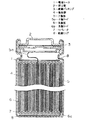
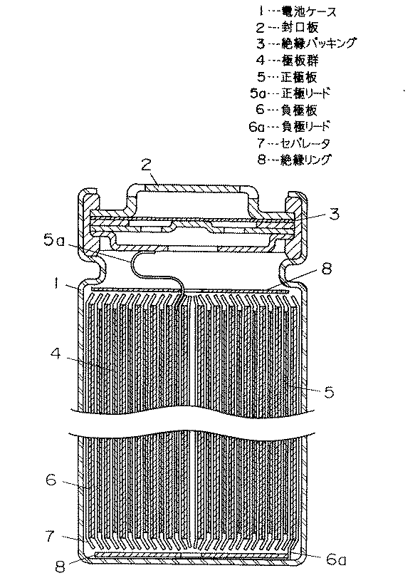
図1に本発明における円筒型電池の縦断面図を示す。正極板5及び負極板6がセパレータ7を介して複数回渦巻状に巻回されて電池ケース1内に収納されている。そして、上記正極板5からは正極リード5aが引き出されて封口板2に接続され、負極板6からは負極リード6aが引き出されて電池ケース1の底部に接続されている。電池ケースやリード板は、耐有機電解液性の電子伝導性をもつ金属や合金を用いることができる。例えば、鉄、ニッケル、チタン、クロム、モリブデン、銅、アルミニウムなどの金属あるいはそれらの合金が用いられる。特に、電池ケースはステンレス鋼板、Al−Mn合金板を加工したもの、正極リードはアルミニウム、負極リードはニッケルが最も好ましい。また、電池ケースには、軽量化を図るため各種エンジニアリングプラスチックス及びこれと金属の併用したものを用いることも可能である。8は絶縁リングで極板群4の上下部にそれぞれ設けられている。そして、電解液を注入し、封口板を用いて電池缶を形成する。このとき、安全弁を封口板として用いることができる。安全弁の他、従来から知られている種々の安全素子を備えつけても良い。例えば、過電流防止素子として、ヒューズ、バイメタル、PTC素子などが用いられる。また、安全弁のほかに電池ケースの内圧上昇の対策として、電池ケースに切込を入れる方法、ガスケット亀裂方法あるいは封口板亀裂方法あるいはリード板との切断方法を利用することができる。また、充電器に過充電や過放電対策を組み込んだ保護回路を具備させるか、あるいは、独立に接続させてもよい。また、過充電対策として、電池内圧の上昇により電流を遮断する方式を具備することができる。このとき、内圧を上げる化合物を合剤の中あるいは電解質の中に含ませることができる。内圧を上げる化合物としてはLi2CO3 、LiHCO3、Na2CO3 、NaHCO3 、CaCO3 、MgCO3 などの炭酸塩などがあげられる。キャップ、電池ケース、シート、リード板の溶接法は、公知の方法(例、直流又は交流の電気溶接、レーザー溶接、超音波溶接)を用いることができる。封口用シール剤は、アスファルトなどの従来から知られている化合物や混合物を用いることができる。
【0050】
負極板6は、得られた前記液状合金を被覆した合金粉末負極材料75重量%に対し、導電材である炭素粉末20重量%と結着剤のポリフッ化ビニリデン樹脂5重量%を混合し、これらを脱水N−メチルピロリジノンに分散させてスラリーを作製し、銅箔からなる負極集電体上に塗布し、乾燥後、圧延して作製した。
【0051】
一方、正極板5は、コバルト酸リチウム粉末85重量%に対し、導電材の炭素粉末10重量%と結着剤のポリフッ化ビニリデン樹脂5重量%を混合し、これらを脱水N−メチルピロリジノンに分散させてスラリーを作製し、アルミ箔からなる正極集電体上に塗布し、乾燥後、圧延して作製した。
【0052】
また、有機電解液には、エチレンカーボネートとエチルメチルカーボネートの体積比1:1の混合溶媒に、LiPF6を1.5モル/リットル溶解したものを使用した。
【0053】
以上のようにして、(表2)に示す材料A〜Sを負極に用いた電池A〜Sを作製した。尚、作製した円筒型電池は直径18mm、高さ65mmである。これらの電池を100mAの定電流で、まず4.1Vになるまで充電した後、100mAの定電流で2.0Vになるまで放電する充放電サイクルを繰り返した。また充放電は20℃の恒温槽の中で行った。尚、充放電は100サイクルまで繰り返し行い、初期の放電容量に対する100サイクル目の放電容量の比を容量維持率として(表2)に示す。
【0054】
【表2】
なお本実施例で用いた負極材料を構成する元素は、固相AがSnの場合、2族元素としてMg、遷移元素としてFeおよびMo、12族元素としてZnおよびCd、13族元素としてIn、14族元素としてPbを用いたが、これら以外の各族の元素を用いても同様な効果が得られた。また固相AがSiの場合、2族元素としてMg、遷移元素としてCoおよびNi、12族元素としてZn、13族元素としてAl、14族元素としてSnを用いたが、これら以外の各族の元素を用いても同様な効果が得られた。また固相AがZnの場合、2族元素としてMg、遷移元素としてCuおよびV、12族元素としてCd、13族元素としてAl、14族元素としてGeを用いたが、これら以外の各族の元素を用いても同様な効果が得られた。
【0056】
また負極材料構成元素の仕込み比率については、特に限定されたものではなく、相が2相になり、1相(固相A)が主にSn、Si、Znを主体とした相で、もう一つ別の相(固相B)がその周りを一部または全部を被覆するような状態になればよく、仕込み組成を特に限定するものではない。さらに、相Aは、Sn、Si、Znのみからだけではなく、各元素以外の元素、例えば、O、C、N、S、Ca、Mg、Al、Fe、W、V、Ti、Cu、Cr、Co、P等の元素が微量存在している場合も含まれる。相Bは表1に示した固溶体、金属間化合物のみからなるだけではなく、それぞれの各固溶体、金属間化合物を構成している元素やそれ以外の元素、例えば、O、C、N、S、Ca、Mg、Al、Fe、W、V、Ti、Cu、Cr、Co、P等の元素が微量存在している場合も含まれる。
【0057】
【発明の効果】
以上のように本発明は、合金複合粒子の表面を低融点合金で覆うことにより、前記複合粒子表面の高抵抗被膜の生成を防止したり、粒子内の伝導ネットワーク機能を防止することができ、高容量で、かつサイクル特性、高率充放電特性に優れた非水電解質二次電池が得られる。
【図面の簡単な説明】
【図1】本発明の円筒形電池の縦断面図
【符号の説明】
1 電池ケース
2 封口板
4 極板群
5 正極板
6 負極板
7 セパレータ[0001]
BACKGROUND OF THE INVENTION
The present invention relates to a non-aqueous electrolyte secondary battery, particularly to a negative electrode material thereof.
[0002]
[Prior art]
In recent years, lithium secondary batteries used as a main power source for mobile communication devices and portable electronic devices have a high electromotive force and a high energy density. A lithium secondary battery using lithium metal as a negative electrode material has a high energy density, but dendrites are deposited on the negative electrode during charging, and the battery may break through the separator and repeatedly reach the positive electrode due to repeated charge and discharge, causing an internal short circuit. there were. In addition, the deposited dendrites have a high specific surface area and thus have high reaction activity, and react with the solvent in the electrolytic solution on the surface to form a solid electrolyte-like interface film lacking in electron conductivity. For this reason, the internal resistance of the battery is increased, or particles isolated from the electron conduction network are present, which are factors that lower the charge / discharge efficiency. For these reasons, lithium secondary batteries using lithium metal as a negative electrode material have problems with low reliability and short cycle life.
[0003]
Currently, carbon materials capable of occluding and releasing lithium ions are used as a negative electrode material to replace lithium metal, and have been put into practical use. Usually, metallic lithium does not precipitate on the carbon material negative electrode, so there is no problem of internal short circuit due to dendrite. However, the theoretical capacity of graphite, which is one of the carbon materials, is 372 mAh / g, which is as low as about 1/10 of the theoretical capacity of Li metal alone.
[0004]
As other negative electrode materials, simple metal materials and simple non-metal materials that form a compound with lithium are known. For example, the composition formulas of silicon (Si) (US Pat. No. 3,969,139), tin (Sn) (US Pat. No. 4,436,796), and zinc (Zn) containing the most lithium are Li, respectively. twenty two Si Five , Li twenty two Sn Five LiZn, and in this range, metallic lithium does not normally precipitate, so there is no problem of internal short circuit due to dendrites. The electrochemical capacities between these compounds and each single material are 4199 mAh / g, 993 mAh / g, and 410 mAh / g, respectively, all of which are larger than the theoretical capacity of graphite.
[0005]
Moreover, as a compound negative electrode material in addition to a simple metal material and a simple non-metal material which form a compound with lithium, JP-A-4-126371, JP-A-7-29602, JP-A-7-240201, JP-A-8 No. -153517 discloses an intermetallic compound composed of a transition element, etc., and JP-A-9-63651 discloses an intermetallic compound containing a group 4B element and at least one of P and Sb, and its crystal structure is CaF. 2 A negative electrode material made of any one of a type, a ZnS type, and an AlLiSi type has been proposed. In addition, Japanese Patent Application Laid-Open No. 10-294112 proposes the use of a superquenched metal silicide as a negative electrode material, and Japanese Patent Application Laid-Open No. 11-86853 includes an intermetallic compound phase and is included in this intermetallic compound. The use of particles containing at least one phase other than the intermetallic compound composed of elements has been proposed.
[0006]
[Problems to be solved by the invention]
However, negative electrode materials having a capacity higher than that of the carbon material as described above have the following problems.
[0007]
A single metal material and a single non-metal negative electrode material that form a compound with lithium are commonly inferior in charge / discharge cycle characteristics compared to a carbon negative electrode material. The reason for this is that the volume difference associated with insertion and extraction of lithium during charging and discharging increases, so that large distortion and cracks occur in the material, and the particles are considered to be finer. Furthermore, it is considered that a space is generated between the fine particles, the electron conduction network is divided, the portion that cannot participate in the electrochemical reaction increases, and the charge / discharge capacity decreases.
[0008]
In other words, the large volume change common to the negative electrode material of the single metal material and the single nonmetal material that form a compound with lithium, and the structural change caused by this, are inferred that the charge / discharge cycle characteristics are deteriorated compared to the carbon negative electrode material. Is done.
[0009]
On the other hand, unlike the above-mentioned simple material, it consists of a non-ferrous metal silicide composed of a transition element, an intermetallic compound containing at least one of group 4B elements and P and Sb, and its crystal structure is CaF. 2 A negative electrode material composed of any one of a type, ZnS type, and AlLiSi type has been proposed in Japanese Patent Application Laid-Open Nos. 7-240201 and 9-63651 as negative electrode materials having improved cycle life characteristics.
[0010]
A battery using a non-ferrous metal silicide negative electrode material composed of a transition element disclosed in JP-A-7-240201 has improved charge / discharge cycle characteristics compared to a lithium metal negative electrode material. The capacity has increased by only about 12% at the maximum. Therefore, a non-ferrous metal silicide negative electrode material made of a transition element is not expected to have a significant capacity increase as compared with a graphite negative electrode material.
[0011]
Moreover, it is shown that the material shown by Unexamined-Japanese-Patent No. 9-63651 has the charging / discharging cycling characteristics improved rather than Li-Pb alloy negative electrode material, and a higher capacity | capacitance than a graphite negative electrode material. . However, the discharge capacity is remarkably reduced in the charge / discharge cycle up to 10-20 cycles, and Mg which seems to be the best 2 Also in Sn, after about 20 cycles, it decreases to about 70% of the initial capacity. The material described in, for example, Japanese Patent Application Laid-Open No. 4-126371 and Japanese Patent Application Laid-Open No. 7-29602, which is provided with a single material and its intermetallic compound, can maintain its structure by the action of an intermetallic compound or an alloy rather than a single material. However, since there is an interface where the single material itself reacts directly with the electrolyte, there is no contribution to maintaining the structure by intermetallic compounds or alloys in this part, and the behavior of the single material It will be the same. Therefore, it has been difficult to obtain sufficient cycle characteristics.
[0012]
The material described in, for example, Japanese Patent Laid-Open No. 8-153517 using nickel silicide as a negative electrode material has excellent cycle characteristics, but the existence ratio of a single material is extremely small, so that characteristics with high capacity density can be obtained. It was difficult.
[0013]
In addition, the material described in, for example, Japanese Patent Application Laid-Open No. 10-294112, which is obtained by ultra-cooling with a charged composition in which the ratio of a single element element to a transition metal element is increased, can surely provide a high capacity because the ratio of the single material is large. In all of the particles, the single material and the intermetallic compound cannot be combined or clathrated, and it is difficult to maintain the structure by the action of the intermetallic compound. In this case, there is a direct reaction interface between the single material and the electrolyte, and the contribution of an intermetallic compound or the like that maintains the structure cannot be obtained, which is similar to the behavior of the single material. Therefore, it has been difficult to obtain sufficient cycle characteristics.
[0014]
As described above, in the nonaqueous electrolyte secondary battery using the conventional alloy negative electrode, the frequency of exposure to the electrolyte solution of the single material component is controlled, and the conduction due to the sequential change of the alloy structure or the surface form during charging and discharging. It was difficult to repair the deterioration of the network function.
[0015]
[Means for Solving the Problems]
In order to solve the above problems, a non-aqueous electrolyte secondary battery including a negative electrode having an alloy containing at least one of silicon, tin, and zinc as a constituent element of the present invention includes a nucleus comprising a solid phase A as the alloy material. A composite particle in which the entire surface or part of the periphery of the particle is coated with a solid phase B, and the surface of the composite particle is covered with a low melting point alloy containing gallium and at least one element of indium, tin, or zinc. (Solid phase A includes at least one of silicon, tin, and zinc as constituent elements, and solid phase B includes any one of constituent elements of solid phase A, silicon, tin, and zinc, and the constituent elements. In addition, a solid solution with at least one element selected from the group consisting of
[0016]
By using the alloy negative electrode having such a form, it is possible to prevent the formation of a high-resistance coating on the particle surface, or to prevent the conduction network function in the particle from being lowered, thereby achieving high capacity, cycle characteristics, and high performance. A nonaqueous electrolyte secondary battery excellent in rate charge / discharge characteristics is obtained.
[0017]
DETAILED DESCRIPTION OF THE INVENTION
The present invention is a negative electrode having an alloy containing at least one of silicon, tin, and zinc as a constituent element. The negative electrode has a structure in which the entire surface or a part of the periphery of a core particle composed of a solid phase A is formed by a solid phase B. The composite particle is coated, the solid phase A includes at least one of silicon, tin, and zinc as constituent elements, and the solid phase B includes any one of silicon, tin, and zinc that are constituent elements of the solid phase A, and the constituent elements. In addition, a material that is a solid solution with at least one element selected from the group consisting of
[0018]
In the negative electrode material of the present invention, the solid phase A contains at least one of high-capacity silicon, tin, and zinc as a constituent element, and thus is considered to contribute mainly to an increase in charge / discharge capacity. In addition, the solid phase B covering the entire surface or a part of the periphery of the core particle composed of the solid phase A contributes to the improvement of charge / discharge cycle characteristics by preventing direct contact with the electrolyte of the solid phase A. In addition, the amount of lithium contained in the solid phase B is usually smaller than that of a single metal, solid solution, or intermetallic compound. In addition, since the eutectic alloy containing at least one metal element of indium, tin, or zinc containing gallium that is liquid at room temperature is coated on the surface of the composite particle that is the negative electrode active material, electron conduction between the alloy composite particles It exerts a flexible tension effect on volumetric changes such as imparting properties, further reducing the direct contact of the solid phase A with the electrolyte, and changing the structure / surface morphology associated with charge and discharge, and expansion and contraction.
[0019]
The positive electrode and negative electrode used in the present invention have a positive electrode active material capable of electrochemically and reversibly inserting and releasing lithium ions and a mixture layer containing a conductive material, a binder and the like on the surface of the current collector. It was made by painting.
[0020]
As one of the methods for producing composite particles of the negative electrode alloy used in the present invention, the melt for the charged composition of each element constituting the composite particles is obtained by a dry spray method, a wet spray method, a roll quench method, and a rotating electrode method. There is a method of rapidly cooling and solidifying by, for example, heat-treating the solidified product at a temperature lower than the solidus temperature of the solid solution or intermetallic compound determined from the charged composition. The composite particles according to claim 1 can be obtained by precipitating the solid phase A particles and the solid phase B covering the whole or part of the periphery of the solid phase A particles as core particles by rapid solidification of the melt. it can. Also, methods other than the above cooling method can be used as long as they can be sufficiently cooled.
[0021]
As another manufacturing method, an adhesion layer made of an element other than the elements contained in the solid phase A necessary for forming the solid phase B is formed on the surface of the powder of the solid phase A, and this is obtained from the charged composition. There is a method of performing heat treatment at a temperature lower than the solidus temperature of the determined solid solution or intermetallic compound. By this heat treatment, the component elements in the solid phase A diffuse into the adhesion layer, and the solid phase B is formed as a coating layer. The adhesion layer can be formed by a plating method or a mechanical alloying method. In addition, any method that can form an adhesion layer can be used.
[0022]
Further, as a low melting point alloy to be coated on the composite particles of the active material alloy, for example, there is a eutectic alloy of gallium, indium and tin, and it is known that the melting point of this alloy is low and is around 5 ° C. Utilizing such a property that is liquid near room temperature, when a predetermined amount of the composite particles of the liquid eutectic alloy and the negative electrode active material alloy are added and mixed in, for example, a methanol solution, the surface is covered with a new liquid alloy. Composite particles can be obtained.
[0023]
The negative electrode conductive material used in the present invention may be anything as long as it is an electron conductive material. For example, natural graphite (such as flake graphite), graphite such as artificial graphite and expanded graphite, carbon black such as acetylene black, ketjen black, channel black, furnace black, lamp black, thermal black, carbon fiber, Conductive fibers such as metal fibers, metal powders such as copper and nickel, and organic conductive materials such as polyphenylene derivatives can be contained alone or as a mixture thereof. Among these conductive materials, artificial graphite, acetylene black, and carbon fiber are particularly preferable. The addition amount of the conductive material is not particularly limited, but is preferably 1 to 50% by weight, and particularly preferably 1 to 30% by weight with respect to the negative electrode material. Moreover, since the negative electrode material of the present invention itself has electronic conductivity, it can function as a battery without adding a conductive material.
[0024]
The negative electrode binder used in the present invention may be either a thermoplastic resin or a thermosetting resin. Preferred binders in the present invention include, for example, polyethylene, polypropylene, polytetrafluoroethylene (PTFE), polyvinylidene fluoride (PVDF), styrene butadiene rubber, tetrafluoroethylene-hexafluoroethylene copolymer, tetrafluoroethylene-hexa. Fluoropropylene copolymer (FEP), tetrafluoroethylene-perfluoroalkyl vinyl ether copolymer (PFA), vinylidene fluoride-hexafluoropropylene copolymer, vinylidene fluoride-chlorotrifluoroethylene copolymer, ethylene-tetra Fluoroethylene copolymer (ETFE resin), polychlorotrifluoroethylene (PCTFE), vinylidene fluoride-pentafluoropropylene copolymer, propylene-tetrafluoroethylene Polymer, ethylene-chlorotrifluoroethylene copolymer (ECTFE), vinylidene fluoride-hexafluoropropylene-tetrafluoroethylene copolymer, vinylidene fluoride-perfluoromethyl vinyl ether-tetrafluoroethylene copolymer, ethylene-acrylic The acid copolymer or (Na + ) Ion-crosslinked product, ethylene-methacrylic acid copolymer or (Na + ) Ionic cross-linked product, ethylene-methyl acrylate copolymer or (Na + ) Ionic cross-linked product, ethylene-methyl methacrylate copolymer or (Na + ) An ionic crosslinked body can be mentioned, and these materials can be used alone or as a mixture. Among these materials, more preferable materials are styrene butadiene rubber, polyvinylidene fluoride, ethylene-acrylic acid copolymer, or (Na + ) Ion-crosslinked product, ethylene-methacrylic acid copolymer or (Na + ) Ionic cross-linked product, ethylene-methyl acrylate copolymer or (Na + ) Ionic cross-linked product, ethylene-methyl methacrylate copolymer or (Na + ) An ionic cross-linked product.
[0025]
The negative electrode current collector used in the present invention may be anything as long as it is an electronic conductor that does not cause a chemical change in the constructed battery. For example, in addition to stainless steel, nickel, copper, titanium, carbon, conductive resin, etc., materials obtained by treating the surface of copper or stainless steel with carbon, nickel, or titanium are used. In particular, copper or a copper alloy is preferable. The surface of these materials can be oxidized and used. Further, it is desirable to make the current collector surface uneven by surface treatment. As the shape, a film, a sheet, a net, a punched one, a lath body, a porous body, a foamed body, a molded body of a fiber group, and the like are used in addition to the foil. The thickness is not particularly limited, but a thickness of 1 to 500 μm is used.
[0026]
A lithium-containing transition metal oxide can be used for the positive electrode material used in the present invention. For example, Li x CoO 2 , Li x NiO 2 , Li x MnO 2 , Li x Co y Ni 1-y O 2 , Li x Co y M 1-y O z , Li x Ni 1-y M y O z , Li x Mn 2 O Four , Li x Mn 2-y M y O Four (M = Na, Mg, Sc, Y, Mn, Fe, Co, Ni, Cu, Zn, Al, Cr, Pb, Sb, B) (where x = 0 to 1.2, y = 0 to 0.9, z = 2.0 to 2.3). Here, said x value is a value before the start of charging / discharging, and it increases / decreases by charging / discharging. However, other positive electrode materials such as transition metal chalcogenides, vanadium oxides and lithium compounds thereof, niobium oxides and lithium compounds thereof, conjugated polymers using organic conductive substances, and chevrel phase compounds can also be used. . It is also possible to use a mixture of a plurality of different positive electrode materials. The average particle diameter of the positive electrode active material particles is not particularly limited, but is preferably 1 to 30 μm.
[0027]
The positive electrode conductive material used in the present invention may be any electron conductive material that does not cause a chemical change at the charge / discharge potential of the positive electrode material used. For example, natural graphite (such as flake graphite), graphite such as artificial graphite, carbon black such as acetylene black, ketjen black, channel black, furnace black, lamp black, thermal black, carbon fiber, metal fiber, etc. Conductive fibers, metal powders such as carbon fluoride and aluminum, conductive whiskers such as zinc oxide and potassium titanate, conductive metal oxides such as titanium oxide, and organic conductive materials such as polyphenylene derivatives It can be included alone or as a mixture thereof. Among these conductive materials, artificial graphite and acetylene black are particularly preferable. The addition amount of the conductive material is not particularly limited, but is preferably 1 to 50% by weight, and particularly preferably 1 to 30% by weight with respect to the positive electrode material. In the case of carbon or graphite, 2 to 15% by weight is particularly preferable.
[0028]
The positive electrode binder used in the present invention may be either a thermoplastic resin or a thermosetting resin. Preferred binders in the present invention include, for example, polyethylene, polypropylene, polytetrafluoroethylene (PTFE), polyvinylidene fluoride (PVDF), styrene butadiene rubber, tetrafluoroethylene-hexafluoroethylene copolymer, tetrafluoroethylene. -Hexafluoropropylene copolymer (FEP), tetrafluoroethylene-perfluoroalkyl vinyl ether copolymer (PFA), vinylidene fluoride-hexafluoropropylene copolymer, vinylidene fluoride-chlorotrifluoroethylene copolymer, ethylene -Tetrafluoroethylene copolymer (ETFE resin), polychlorotrifluoroethylene (PCTFE), vinylidene fluoride-pentafluoropropylene copolymer, propylene-tetrafluoroethylene Polymer, ethylene-chlorotrifluoroethylene copolymer (ECTFE), vinylidene fluoride-hexafluoropropylene-tetrafluoroethylene copolymer, vinylidene fluoride-perfluoromethyl vinyl ether-tetrafluoroethylene copolymer, ethylene-acrylic The acid copolymer or (Na + ) Ion-crosslinked product, ethylene-methacrylic acid copolymer or (Na + ) Ionic cross-linked product, ethylene-methyl acrylate copolymer or (Na + ) Ionic cross-linked product, ethylene-methyl methacrylate copolymer or (Na + ) An ionic crosslinked body can be mentioned, and these materials can be used alone or as a mixture. Among these materials, more preferable materials are polyvinylidene fluoride (PVDF) and polytetrafluoroethylene (PTFE).
[0029]
The positive electrode current collector used in the present invention may be any electronic conductor that does not cause a chemical change in the charge / discharge potential of the positive electrode material used. For example, in addition to stainless steel, aluminum, titanium, carbon, conductive resin, etc., materials obtained by treating carbon or titanium on the surface of aluminum or stainless steel are used. In particular, aluminum or an aluminum alloy is preferable. The surface of these materials can be oxidized and used. Further, it is desirable to make the current collector surface uneven by surface treatment. As the shape, a film, a sheet, a net, a punched product, a lath body, a porous body, a foamed body, a fiber group, a non-woven body shaped body, and the like are used in addition to the foil. The thickness is not particularly limited, but a thickness of 1 to 500 μm is used.
[0030]
In addition to the conductive material and the binder, a filler, a dispersant, an ionic conductor, a pressure enhancer, and other various additives can be used for the electrode mixture. Any filler can be used as long as it is a fibrous material that does not cause a chemical change in the constructed battery. Usually, olefin polymers such as polypropylene and polyethylene, fibers such as glass and carbon are used. Although the addition amount of a filler is not specifically limited, 0 to 30 weight% is preferable with respect to an electrode mixture.
[0031]
In the configuration of the negative electrode plate and the positive electrode plate in the present invention, it is preferable that the negative electrode mixture surface is present at least on the opposite surface of the positive electrode mixture surface.
[0032]
The nonaqueous electrolyte used in the present invention is composed of a solvent and a lithium salt dissolved in the solvent. Examples of the non-aqueous solvent include ethylene carbonate (EC), propylene carbonate (PC), butylene carbonate (BC), cyclic carbonates such as vinylene carbonate (VC), dimethyl carbonate (DMC), Chain carbonates such as diethyl carbonate (DEC), ethyl methyl carbonate (EMC), dipropyl carbonate (DPC), aliphatic carboxylic acid esters such as methyl formate, methyl acetate, methyl propionate, ethyl propionate, γ- Γ-lactones such as butyrolactone, chain ethers such as 1,2-dimethoxyethane (DME), 1,2-diethoxyethane (DEE), ethoxymethoxyethane (EME), tetrahydrofuran, 2-methyltetrahydrofuran, etc. Cyclic ethers, dimethylsulfur Hoxide, 1,3-dioxolane, formamide, acetamide, dimethylformamide, dioxolane, acetonitrile, propylnitrile, nitromethane, ethyl monoglyme, phosphate triester, trimethoxymethane, dioxolane derivative, sulfolane, methylsulfolane, 1,3-dimethyl Aprotic organic solvents such as 2-imidazolidinone, 3-methyl-2-oxazolidinone, propylene carbonate derivatives, tetrahydrofuran derivatives, ethyl ether, 1,3-propane sultone, anisole, dimethyl sulfoxide, N-methylpyrrolidone These may be used alone or in combination of two or more. Among these, a mixed system of a cyclic carbonate and a chain carbonate or a mixed system of a cyclic carbonate, a chain carbonate, and an aliphatic carboxylic acid ester is preferable.
[0033]
Examples of the lithium salt dissolved in these solvents include LiClO. Four , LiBF Four , LiPF 6 LiAlCl Four , LiSbF 6 , LiSCN, LiCl, LiCF Three SO Three , LiCF Three CO 2 , Li (CF Three SO 2 ) 2 , LiAsF 6 , LiN (CF Three SO 2 ) 2 , LiB Ten Cl Ten , Lower aliphatic lithium carboxylate, LiCl, LiBr, LiI, chloroborane lithium, lithium tetraphenylborate, imides, etc., and these can be used singly or in combination of two or more. In particular, LiPF 6 It is more preferable to include.
[0034]
A particularly preferred non-aqueous electrolyte in the present invention contains at least ethylene carbonate and ethyl methyl carbonate, and LiPF as a supporting salt. 6 It is the electrolyte solution containing. The amount of the electrolyte added to the battery is not particularly limited, but a necessary amount can be used depending on the amount of the positive electrode material and the negative electrode material and the size of the battery. The amount of dissolution of the supporting electrolyte in the nonaqueous solvent is not particularly limited, but is preferably 0.2 to 2 mol / l. In particular, 0.5 to 1.5 mol / l is more preferable.
[0035]
In addition to the electrolytic solution, the following solid electrolyte can also be used. The solid electrolyte is classified into an inorganic solid electrolyte and an organic solid electrolyte. Well-known inorganic solid electrolytes include Li nitrides, halides, oxyacid salts, and the like. Among them, Li Four SiO Four , Li Four SiO Four -LiI-LiOH, x Li Three PO Four -(1-x) Li Four SiO Four , Li 2 SiS Three , Li Three PO Four -Li 2 S-SiS 2 In addition, phosphorus sulfide compounds are effective. For organic solid electrolytes, for example, polymer materials such as polyethylene oxide, polypropylene oxide, polyphosphazene, polyaziridine, polyethylene sulfide, polyvinyl alcohol, polyvinylidene fluoride, polyhexafluoropropylene, and derivatives, mixtures, and composites thereof are effective. is there.
[0036]
Furthermore, it is also effective to add other compounds to the electrolyte for the purpose of improving discharge and charge / discharge characteristics. For example, triethyl phosphite, triethanolamine, cyclic ether, ethylenediamine, n-glyme, pyridine, hexaphosphoric triamide, nitrobenzene derivatives, crown ethers, quaternary ammonium salts, ethylene glycol dialkyl ether, and the like can be given.
[0037]
As the separator used in the present invention, an insulating microporous thin film having a large ion permeability and a predetermined mechanical strength is used. Moreover, it is preferable to have a function of closing the hole at a certain temperature or higher and increasing the resistance. A sheet, a nonwoven fabric, or a woven fabric made of an olefin polymer such as polypropylene or polyethylene, or glass fiber, or the like, is used because of its resistance to organic solvents and hydrophobicity. The pore diameter of the separator is desirably in a range in which the positive and negative electrode materials, the binder, and the conductive material detached from the electrode sheet do not permeate, for example, 0.01 to 1 μm is desirable. The thickness of the separator is generally 10 to 300 μm. The porosity is determined according to the permeability of electrons and ions, the material, and the film thickness, but is generally preferably 30 to 80%.
[0038]
A polymer in which an organic electrolytic solution composed of a solvent and a lithium salt dissolved in the solvent is absorbed and held in a polymer material is included in the positive electrode mixture and the negative electrode mixture, and the organic electrolytic solution is absorbed and held. It is also possible to constitute a battery in which a porous separator made of is integrated with a positive electrode and a negative electrode. The polymer material is not particularly limited as long as it can absorb and retain the organic electrolyte solution, but a copolymer of vinylidene fluoride and hexafluoropropylene is particularly preferable.
[0039]
The shape of the battery can be applied to any of a coin type, a button type, a sheet type, a laminated type, a cylindrical type, a flat type, a square type, a large type used for an electric vehicle and the like.
[0040]
Further, the nonaqueous electrolyte secondary battery of the present invention can be used for a portable information terminal, a portable electronic device, a small electric power storage device for home use, a motorcycle, an electric vehicle, a hybrid electric vehicle, etc., but is not particularly limited thereto. I don't mean.
[0041]
【Example】
Hereinafter, the present invention will be described in more detail with reference to examples. However, the present invention is not limited to these examples.
[0042]
The manufacturing method of negative electrode material is shown.
[0043]
In Table 1, the solid phase A and solid phase B components (single element, intermetallic compound, solid solution) of the negative electrode material (material A to material S) used in this example, element ratio at the time of preparation, melting temperature, And the solidus temperature.
[0044]
The powder or block of each element constituting the negative electrode material is charged into the dissolution tank at the charging ratio shown in (Table 1), melted at the melting temperature shown in (Table 1), and the melt is quenched by the roll quenching method. And coagulated to obtain a coagulated product. Subsequently, the solidified product was heat-treated in an inert atmosphere for 20 hours at a temperature lower by about 10 ° C. to 50 ° C. than the solidus temperature of the solid solution or intermetallic compound determined from the charged composition shown in (Table 1). This heat-treated product was pulverized with a ball mill and classified with a sieve to obtain materials A to S having particles of 45 μm or less. From these electron microscope observation results, it was confirmed that the entire surface or part of the periphery of the solid phase A particles was covered with the solid phase B.
[0045]
[Table 1]
The negative electrode alloy powder thus obtained and a gallium-containing alloy were coated in a methanol solvent using a liquid alloy having a composition of gallium: indium: tin = 62: 25: 10 wt%. As a result, the weight increased by about 0.007 to 0.02 wt% with respect to that before the treatment. The reason why the increase in weight is wide is thought to be because the distribution of particle size, specific surface area, pore structure, etc. of the base alloy powder itself varies depending on the alloy type. The composition of the liquid alloy used here is gallium: indium: tin = 62: 25: 10 wt%, for example, gallium: indium = 75.5: 24.5 wt%, gallium: indium: zinc = 67: 29 : 4 wt%, gallium: tin = 92: 8, gallium: zinc = 95: 5 wt%, and the like. If each purity is 4N or more, there is no problem. Of these, the lowest melting point is gallium: indium: tin = 62: 25: 10, which is 5 ° C. On the contrary, the relatively high one is gallium: zinc = 95: 5 wt%, which is 25 ° C.
[0047]
Since the existence state of each element constituting the liquid eutectic alloy added later is different from the existence state of the constituent elements of the composite particles obtained by cooling from around the liquidus temperature used as the active material, there is a common element temporarily. However, they can be distinguished by various instrument analyses, and their functions are also different.
[0048]
Next, a method for manufacturing a cylindrical battery will be described.
[0049]
FIG. 1 is a longitudinal sectional view of a cylindrical battery according to the present invention. The
[0050]
The
[0051]
On the other hand, in the
[0052]
In addition, the organic electrolyte includes a mixed solvent of ethylene carbonate and ethyl methyl carbonate in a volume ratio of 1: 1, and LiPF. 6 In which 1.5 mol / liter was dissolved was used.
[0053]
As described above, batteries A to S using materials A to S shown in (Table 2) as negative electrodes were produced. The produced cylindrical battery has a diameter of 18 mm and a height of 65 mm. These batteries were first charged with a constant current of 100 mA to 4.1 V, and then a charge / discharge cycle in which the batteries were discharged to 2.0 V with a constant current of 100 mA was repeated. Moreover, charging / discharging was performed in a 20 degreeC thermostat. Charging / discharging is repeated up to 100 cycles, and the ratio of the discharge capacity at the 100th cycle to the initial discharge capacity is shown in Table 2 as the capacity retention rate.
[0054]
[Table 2]
When the solid phase A is Sn, the elements constituting the negative electrode material used in this example are Mg as the
[0056]
Further, the preparation ratio of the negative electrode material constituent elements is not particularly limited, and the phase is two phases, and one phase (solid phase A) is a phase mainly composed of Sn, Si, and Zn. There is no particular limitation on the charged composition as long as another phase (solid phase B) covers a part or all of the surroundings. Furthermore, the phase A is not only composed of Sn, Si, Zn but also elements other than each element, for example, O, C, N, S, Ca, Mg, Al, Fe, W, V, Ti, Cu, Cr The case where a trace amount of elements such as Co, P and the like is present is also included. Phase B not only consists of the solid solution and intermetallic compound shown in Table 1, but also each solid solution, elements constituting the intermetallic compound and other elements such as O, C, N, S, The case where trace amounts of elements such as Ca, Mg, Al, Fe, W, V, Ti, Cu, Cr, Co, and P exist is also included.
[0057]
【The invention's effect】
As described above, the present invention covers the surface of the alloy composite particles with a low melting point alloy, thereby preventing the formation of a high-resistance film on the surface of the composite particles, or preventing the conduction network function in the particles, A non-aqueous electrolyte secondary battery having a high capacity and excellent cycle characteristics and high rate charge / discharge characteristics can be obtained.
[Brief description of the drawings]
FIG. 1 is a longitudinal sectional view of a cylindrical battery of the present invention.
[Explanation of symbols]
1 Battery case
2 Sealing plate
4 plate group
5 Positive electrode plate
6 Negative electrode plate
7 Separator
Claims (2)
Priority Applications (1)
| Application Number | Priority Date | Filing Date | Title |
|---|---|---|---|
| JP28130999A JP4635283B2 (en) | 1999-10-01 | 1999-10-01 | Nonaqueous electrolyte secondary battery |
Applications Claiming Priority (1)
| Application Number | Priority Date | Filing Date | Title |
|---|---|---|---|
| JP28130999A JP4635283B2 (en) | 1999-10-01 | 1999-10-01 | Nonaqueous electrolyte secondary battery |
Publications (2)
| Publication Number | Publication Date |
|---|---|
| JP2001102052A JP2001102052A (en) | 2001-04-13 |
| JP4635283B2 true JP4635283B2 (en) | 2011-02-23 |
Family
ID=17637302
Family Applications (1)
| Application Number | Title | Priority Date | Filing Date |
|---|---|---|---|
| JP28130999A Expired - Lifetime JP4635283B2 (en) | 1999-10-01 | 1999-10-01 | Nonaqueous electrolyte secondary battery |
Country Status (1)
| Country | Link |
|---|---|
| JP (1) | JP4635283B2 (en) |
Cited By (2)
| Publication number | Priority date | Publication date | Assignee | Title |
|---|---|---|---|---|
| JP3079151B2 (en) | 1991-12-17 | 2000-08-21 | 三木プーリ株式会社 | Fastener |
| CN103721707A (en) * | 2012-10-15 | 2014-04-16 | 通用汽车环球科技运作有限责任公司 | Preparation of hollow pt and pt-alloy catalysts |
Families Citing this family (14)
| Publication number | Priority date | Publication date | Assignee | Title |
|---|---|---|---|---|
| JP2001291512A (en) * | 2000-04-05 | 2001-10-19 | Matsushita Electric Ind Co Ltd | Non-aqueous electrolyte secondary battery |
| JP4911835B2 (en) * | 2001-06-25 | 2012-04-04 | 日立マクセルエナジー株式会社 | Non-aqueous secondary battery manufacturing method and charging method |
| EP1313158A3 (en) * | 2001-11-20 | 2004-09-08 | Canon Kabushiki Kaisha | Electrode material for rechargeable lithium battery, electrode comprising said electrode material, rechargeable lithium battery having said electrode , and process for the production thereof |
| WO2004049473A2 (en) | 2002-11-26 | 2004-06-10 | Showa Denko K.K. | Electrode material comprising silicon and/or tin particles and production method and use thereof |
| JP4366222B2 (en) * | 2003-03-26 | 2009-11-18 | キヤノン株式会社 | Electrode material for lithium secondary battery, electrode structure having the electrode material, and secondary battery having the electrode structure |
| JP4992128B2 (en) * | 2004-06-02 | 2012-08-08 | パイオニクス株式会社 | Negative electrode active material particles for lithium secondary battery and method for producing negative electrode |
| KR100786864B1 (en) * | 2006-02-10 | 2007-12-20 | 삼성에스디아이 주식회사 | Anode active material for lithium secondary battery, manufacturing method thereof and lithium secondary battery comprising same |
| JP5455183B2 (en) * | 2008-08-04 | 2014-03-26 | Necエナジーデバイス株式会社 | Non-aqueous electrolyte secondary battery |
| JP5272225B2 (en) * | 2009-03-31 | 2013-08-28 | 石原薬品株式会社 | Low melting point metal powder and method for producing the same |
| JP5557793B2 (en) * | 2011-04-27 | 2014-07-23 | 株式会社日立製作所 | Nonaqueous electrolyte secondary battery |
| JP2014038832A (en) * | 2012-07-20 | 2014-02-27 | Sanyo Special Steel Co Ltd | Material for negative electrode of electric power storage device |
| KR101676404B1 (en) * | 2013-10-21 | 2016-11-15 | 주식회사 엘지화학 | Anode active material for lithium secondary battery and Lithium secondary battery comprising the same |
| JP6475531B2 (en) * | 2015-03-26 | 2019-02-27 | 山陽特殊製鋼株式会社 | Powder for filler |
| GB2543836A (en) * | 2015-10-30 | 2017-05-03 | Sharp Kk | Metal-ion rechargeable cell or battery |
Family Cites Families (10)
| Publication number | Priority date | Publication date | Assignee | Title |
|---|---|---|---|---|
| JPS5638669B2 (en) * | 1974-01-14 | 1981-09-08 | ||
| JPS5346418A (en) * | 1976-10-08 | 1978-04-26 | Seiko Epson Corp | Low melting point alloy |
| JPS63274058A (en) * | 1987-05-01 | 1988-11-11 | Fuji Elelctrochem Co Ltd | Negative electrode for nonaqueous electrolyte secondary battery |
| JP2507161B2 (en) * | 1990-09-12 | 1996-06-12 | 松下電器産業株式会社 | Zinc alloy for zinc alkaline battery, method for producing the same, and zinc alkaline battery using the same |
| JP3550190B2 (en) * | 1994-09-03 | 2004-08-04 | 同和鉱業株式会社 | Negative electrode material, method for producing the same, negative electrode body and secondary battery using the same |
| JPH08329929A (en) * | 1995-06-05 | 1996-12-13 | Matsushita Denchi Kogyo Kk | Lithium secondary battery |
| JPH09245799A (en) * | 1996-03-05 | 1997-09-19 | Matsushita Denchi Kogyo Kk | Lithium secondary battery |
| JP4395898B2 (en) * | 1997-06-03 | 2010-01-13 | パナソニック株式会社 | Anode material for non-aqueous electrolyte secondary battery and non-aqueous electrolyte secondary battery using these anode materials |
| JP4449089B2 (en) * | 1998-12-02 | 2010-04-14 | パナソニック株式会社 | Nonaqueous electrolyte secondary battery |
| JP2000173585A (en) * | 1998-12-02 | 2000-06-23 | Matsushita Electric Ind Co Ltd | Non-aqueous electrolyte secondary battery |
-
1999
- 1999-10-01 JP JP28130999A patent/JP4635283B2/en not_active Expired - Lifetime
Cited By (2)
| Publication number | Priority date | Publication date | Assignee | Title |
|---|---|---|---|---|
| JP3079151B2 (en) | 1991-12-17 | 2000-08-21 | 三木プーリ株式会社 | Fastener |
| CN103721707A (en) * | 2012-10-15 | 2014-04-16 | 通用汽车环球科技运作有限责任公司 | Preparation of hollow pt and pt-alloy catalysts |
Also Published As
| Publication number | Publication date |
|---|---|
| JP2001102052A (en) | 2001-04-13 |
Similar Documents
| Publication | Publication Date | Title |
|---|---|---|
| JP4399881B2 (en) | Nonaqueous electrolyte secondary battery | |
| JP4457429B2 (en) | Nonaqueous electrolyte secondary battery and its negative electrode | |
| JP4767428B2 (en) | Nonaqueous electrolyte secondary battery | |
| JP4635283B2 (en) | Nonaqueous electrolyte secondary battery | |
| JP3882447B2 (en) | Nonaqueous electrolyte secondary battery | |
| JP2000173585A (en) | Non-aqueous electrolyte secondary battery | |
| JP4056180B2 (en) | Negative electrode active material for non-aqueous electrolyte secondary battery and non-aqueous electrolyte secondary battery | |
| JP4534266B2 (en) | Nonaqueous electrolyte secondary battery | |
| JP2000173586A (en) | Non-aqueous electrolyte secondary battery | |
| JP4534265B2 (en) | Nonaqueous electrolyte secondary battery | |
| JP4487326B2 (en) | Non-aqueous electrolyte secondary battery charging method | |
| JP4449094B2 (en) | Nonaqueous electrolyte secondary battery | |
| JP4432130B2 (en) | Nonaqueous electrolyte secondary battery | |
| JP4399879B2 (en) | Nonaqueous electrolyte secondary battery | |
| JP2001210323A (en) | Non-aqueous electrolyte secondary battery | |
| JP4432129B2 (en) | Nonaqueous electrolyte secondary battery | |
| JP4399880B2 (en) | Nonaqueous electrolyte secondary battery | |
| JP4449090B2 (en) | Nonaqueous electrolyte secondary battery | |
| JP4449089B2 (en) | Nonaqueous electrolyte secondary battery | |
| JP4487325B2 (en) | Non-aqueous electrolyte secondary battery charging method | |
| JP4399876B2 (en) | Nonaqueous electrolyte secondary battery | |
| JP4432132B2 (en) | Nonaqueous electrolyte secondary battery | |
| JP4432128B2 (en) | Nonaqueous electrolyte secondary battery | |
| JP4432131B2 (en) | Nonaqueous electrolyte secondary battery | |
| JP4399877B2 (en) | Nonaqueous electrolyte secondary battery |
Legal Events
| Date | Code | Title | Description |
|---|---|---|---|
| A621 | Written request for application examination |
Free format text: JAPANESE INTERMEDIATE CODE: A621 Effective date: 20060920 |
|
| RD01 | Notification of change of attorney |
Free format text: JAPANESE INTERMEDIATE CODE: A7421 Effective date: 20061012 |
|
| A977 | Report on retrieval |
Free format text: JAPANESE INTERMEDIATE CODE: A971007 Effective date: 20090716 |
|
| A131 | Notification of reasons for refusal |
Free format text: JAPANESE INTERMEDIATE CODE: A131 Effective date: 20090728 |
|
| A521 | Request for written amendment filed |
Free format text: JAPANESE INTERMEDIATE CODE: A523 Effective date: 20090911 |
|
| RD01 | Notification of change of attorney |
Free format text: JAPANESE INTERMEDIATE CODE: A7421 Effective date: 20091119 |
|
| TRDD | Decision of grant or rejection written | ||
| A01 | Written decision to grant a patent or to grant a registration (utility model) |
Free format text: JAPANESE INTERMEDIATE CODE: A01 Effective date: 20101026 |
|
| A01 | Written decision to grant a patent or to grant a registration (utility model) |
Free format text: JAPANESE INTERMEDIATE CODE: A01 |
|
| A61 | First payment of annual fees (during grant procedure) |
Free format text: JAPANESE INTERMEDIATE CODE: A61 Effective date: 20101108 |
|
| FPAY | Renewal fee payment (event date is renewal date of database) |
Free format text: PAYMENT UNTIL: 20131203 Year of fee payment: 3 |
|
| R151 | Written notification of patent or utility model registration |
Ref document number: 4635283 Country of ref document: JP Free format text: JAPANESE INTERMEDIATE CODE: R151 |
|
| FPAY | Renewal fee payment (event date is renewal date of database) |
Free format text: PAYMENT UNTIL: 20131203 Year of fee payment: 3 |
|
| EXPY | Cancellation because of completion of term |