JP4630548B2 - Apparatus and trough drum for organizing groups of filter segments to produce multi-segment filters for the tobacco processing industry - Google Patents
Apparatus and trough drum for organizing groups of filter segments to produce multi-segment filters for the tobacco processing industry Download PDFInfo
- Publication number
- JP4630548B2 JP4630548B2 JP2003528159A JP2003528159A JP4630548B2 JP 4630548 B2 JP4630548 B2 JP 4630548B2 JP 2003528159 A JP2003528159 A JP 2003528159A JP 2003528159 A JP2003528159 A JP 2003528159A JP 4630548 B2 JP4630548 B2 JP 4630548B2
- Authority
- JP
- Japan
- Prior art keywords
- filter
- drum
- segment
- trough
- segments
- Prior art date
- Legal status (The legal status is an assumption and is not a legal conclusion. Google has not performed a legal analysis and makes no representation as to the accuracy of the status listed.)
- Expired - Fee Related
Links
Images


Classifications
-
- A—HUMAN NECESSITIES
- A24—TOBACCO; CIGARS; CIGARETTES; SIMULATED SMOKING DEVICES; SMOKERS' REQUISITES
- A24D—CIGARS; CIGARETTES; TOBACCO SMOKE FILTERS; MOUTHPIECES FOR CIGARS OR CIGARETTES; MANUFACTURE OF TOBACCO SMOKE FILTERS OR MOUTHPIECES
- A24D3/00—Tobacco smoke filters, e.g. filter-tips, filtering inserts; Filters specially adapted for simulated smoking devices; Mouthpieces for cigars or cigarettes
- A24D3/02—Manufacture of tobacco smoke filters
- A24D3/0275—Manufacture of tobacco smoke filters for filters with special features
- A24D3/0287—Manufacture of tobacco smoke filters for filters with special features for composite filters
-
- A—HUMAN NECESSITIES
- A24—TOBACCO; CIGARS; CIGARETTES; SIMULATED SMOKING DEVICES; SMOKERS' REQUISITES
- A24C—MACHINES FOR MAKING CIGARS OR CIGARETTES
- A24C5/00—Making cigarettes; Making tipping materials for, or attaching filters or mouthpieces to, cigars or cigarettes
- A24C5/47—Attaching filters or mouthpieces to cigars or cigarettes, e.g. inserting filters into cigarettes or their mouthpieces
- A24C5/478—Transport means for filter- or cigarette-rods in view of their assembling
Abstract
Description
本発明は、マルチセグメントフィルタ毎に、少なくとも2つの異なる種類のフィルタセグメントが設けられている、連続方法でたばこ加工産業のマルチセグメントフィルタを製造するためにフィルタセグメントのグループを編成するための装置に関する。 The present invention relates to an apparatus for organizing a group of filter segments in order to produce a multi-segment filter in the tobacco processing industry in a continuous manner, wherein each multi-segment filter is provided with at least two different types of filter segments. .
たばこ加工産業では、例えば異なる材料製の異なるセグメントからなるマルチセグメントフィルタを製造することが所望される。この材料は、例えば酢酸セルロース、紙、フリース、顆粒、焼結要素、中空円筒または中空室、カプセル等である。本発明の範囲において用語“多重フィルタ”も含むこのようなマルチセグメントフィルタは、フィルタセグメントのグループを形成した後で、例えば連続方法で、例えば紙のように被覆材料で被覆され、更に加工するために2倍、4倍または6倍の長さのフィルタロッドに分割される。 In the tobacco processing industry, it is desirable to produce multi-segment filters, for example consisting of different segments made of different materials. This material is, for example, cellulose acetate, paper, fleece, granules, sintered elements, hollow cylinders or chambers, capsules and the like. Such a multi-segment filter, which also includes the term “multiple filter” within the scope of the present invention, is formed in a continuous manner after being formed into a group of filter segments, for example coated with a coating material, for example paper, for further processing. Is divided into filter rods having a length of 2 times, 4 times or 6 times.
英国特許第1522139号公報に対応し、本出願人の権利前任者によって出願された特許文献1により、棒状体形成装置が知られている。この棒状体形成装置の場合、横方向方法で作動するグループ形成装置において、フィルタセグメントのグループまたはフィルタロッドのグループが形成され、そして棒状体形成装置に移送され、フィルタロッドのグループが被覆材料によって縦軸方向に被覆される。この場合、グループ形成装置は、フィルタセグメントの変更時またはフィルタセグメントの順序の変更時に全部を交換しなればならない装置である。
Corresponding to British Patent No. 1522139, a rod-shaped body forming apparatus is known from
これによって、多大の費用がかかり、マルチフィルタ製造時に可変性が小さい。 This is very expensive and has little variability when manufacturing multi-filters.
本出願人の代表的な棒状体形成装置としてKDF 2Eが知られている。本出願人の代表的なグループ形成装置はGC Eと呼ばれている。両装置は、取引サークルにおいて知られており、共にタイプMULFI E の機械として販売されている。 KDF 2E is known as a representative rod-shaped body forming apparatus of the present applicant. Applicant's representative group forming device is called GCE. Both devices are known in the trading circle and are both sold as machines of type MULFI E.
形成されたグループを、グループ形成装置から棒状体形成装置に移送することは、米国特許第特許第4044659号明細書に対応する特許文献2に記載されている。この特許文献2と特許文献1は、参照することによってこの出願の開示内容に収容される。
Transfer of the formed group from the group forming apparatus to the rod-shaped body forming apparatus is described in
更に、本出願人の特許文献3によって、たばこ加工産業の切断される棒状品物を縦軸方向に位置決めするための装置が知られている。この装置の場合、特にトラフドラムが使用される。このトラフドラムによって、連続する段状のフィルタロッドが形成されて、フィルタロッドの分離切断を行うために横軸方向に整列される。
本発明の課題は、マルチフィルタ製造時に可変性を有するように、マルチセグメントフィルタを製造するためにフィルタセグメントのグループを編成するための冒頭に述べた装置を改良することである。この装置は、更に、低コストであるべきであり、しかも特に異なるマルチフィルタの製造の可変性に関しても低コストであるべきである。更に、他の種類のマルチフィルタの製造装置に改造する際に、できるだけ時間を節約すべきである。本発明の他の課題は、マルチセグメントフィルタを製造するためにフィルタセグメントのグループを編成するための装置を省スペース的に形成できるようにすべきである。この場合、更に、このような装置によって実施可能な加工を、短縮された搬送路で実現できるようにすべきである。 The object of the present invention is to improve the apparatus mentioned at the outset for organizing groups of filter segments in order to produce a multi-segment filter so as to have variability when producing the multi-filter. This device should also be low cost, and especially low with respect to the variability in the production of different multifilters. In addition, time should be saved as much as possible when retrofitting to other types of multi-filter manufacturing equipment. Another object of the present invention should be that a device for organizing groups of filter segments in order to produce a multi-segment filter can be formed in a space-saving manner. In this case, it should be further possible to realize processing that can be carried out by such a device with a shortened transport path.
この課題は、マルチセグメントフィルタ毎に、少なくとも2つの異なる種類のフィルタセグメントが設けられている、連続方法でたばこ加工産業のマルチセグメントフィルタを製造するためにフィルタセグメントのグループを編成するための装置において、装置が、グループを構成するフィルタセグメントの種類に応じてそれぞれ使用可能な、それぞれモジュールとして形成された独立した多数の機能ユニットを備え、独立した多数の機能ユニットが一列に配置され、隣接する2つの機能ユニットの搬送要素の少なくとも一部が、フィルタセグメントのグループを編成するために作用連結されており、編成されたフィルタセグメントが、移送装置によって後続の棒状体形成装置に引き渡されること、作用連結可能な搬送要素が、付属する機能ユニットから、グループ内の所定の位置で少なくとも1つのフィルタセグメントを受け取る編成ドラムと、フィルタセグメントをこの編成ドラムから隣の機能ユニットの編成ドラム又は移送装置に引き渡す移送ドラムであり、編成ドラムと移送ドラムが、互いに係合し、一列に水平に配置されており、これにより、各々の機能ユニットから、フィルタセグメントが搬送要素によって横軸方向に搬送され、グループが編成可能であることによって解決される。 The object is to provide an apparatus for organizing a group of filter segments in order to produce a multi-segment filter in the tobacco processing industry in a continuous manner, in which at least two different types of filter segments are provided for each multi-segment filter. , apparatus, each available in accordance with the type of filter segments constituting the group, each with a number of functional units independent formed as a module, independent multiple functional units are arranged in a row, two adjacent One of at least part of the conveying elements of the functional units are acting connected to organize a group of filter segments, the filter segments organized is passed to subsequent rod member forming apparatus by the transfer device, acting connection Possible transport elements are included functions A knitting drum for receiving at least one filter segment from the knit at a predetermined position in the group; and a transfer drum for transferring the filter segment from the knitting drum to a knitting drum or a transfer device of an adjacent functional unit. Are engaged with each other and arranged horizontally in a row, whereby the filter segments are transported by the transport elements in the transverse direction from each functional unit, and the group can be organized .
装置を多数の独立した機能ユニットに分割できるようにすることにより、マルチフィルタ製造の際に最大限の可変性が与えられる。この場合、異なるマルチフィルタの製造を希望する場合、迅速にかつ低コストで適合させることができる。この適合の際、場合によっては独立した機能ユニットの配列を変えて適合させるだけか、例えば少ないモジュールまたは機能ユニットを購入するだけでよい。本発明の範囲内において、用語“機能ユニット”は用語“モジュール”も含んでいる。本願の範囲内において、機能ユニットが分割可能であることは、特に機能ユニットが組み立て可能であることを意味する。 By allowing the device to be divided into a number of independent functional units, maximum variability is provided during multi-filter manufacturing. In this case, if it is desired to produce a different multifilter, it can be adapted quickly and at low cost. In this adaptation, it is only necessary to change the arrangement of the independent functional units in some cases and to adapt them, for example, to purchase fewer modules or functional units. Within the scope of the present invention, the term “functional unit” also includes the term “module”. Within the scope of the present application, the fact that a functional unit can be divided means in particular that the functional unit can be assembled.
マルチセグメントフィルタのフィルタセグメントの種類毎に、1個の機能ユニットが設けられていると、きわめて省スペース的な装置が実現可能である。マルチセグメントフィルタのフィルタセグメント毎に、1個、特に唯一の機能ユニットが設けられていると、装置のきわめて高い可変性が得られる。独立した多数の機能ユニットが一列に配置され、しかも隣接する2つの機能ユニットの搬送要素の少なくとも一部が作用連結可能、特に互いに係合可能であるように、配置されていると、フィルタセグメントのグループのきわめて簡単な編成が達成される。フィルタセグメントは搬送要素によって蛇行形に搬送される。この場合、作用連結部の範囲において、フィルタセグメントが搬送要素から隣接する搬送要素に移送される。この搬送要素上で、フィルタ要素はきわめて簡単に編成することができる。搬送要素は、好ましくは編成ドラムおよび/または移送ドラムを備える。フィルタセグメントまたはフィルタセグメントグループを移送する搬送要素が、一列に水平に配置されていると、装置の構造が有利および簡単になる。各々の機能ユニットは、好ましくは、少なくとも1個の編成ドラムを備える。フィルタセグメントのグループは、好ましくは搬送要素によって横軸方向に搬送可能である。それによって、装置と、独立した機能ユニットをコンパクトに形成することができる。 If one functional unit is provided for each type of filter segment of the multi-segment filter, a very space-saving device can be realized. If one, in particular the only functional unit, is provided for each filter segment of the multi-segment filter, very high variability of the device is obtained. When a plurality of independent functional units are arranged in a line and are arranged such that at least a part of the transport elements of two adjacent functional units can be operatively connected, in particular engageable with one another, A very simple organization of the group is achieved. The filter segment is conveyed in a serpentine form by the conveying element. In this case, the filter segment is transferred from the transport element to the adjacent transport element in the range of the working connection. On this conveying element, the filter elements can be organized very simply. The conveying element preferably comprises a knitting drum and / or a transfer drum. If the conveying elements for transferring the filter segments or filter segment groups are arranged horizontally in a row, the construction of the device is advantageous and simple. Each functional unit preferably comprises at least one knitting drum. The group of filter segments is preferably transportable in the transverse direction by a transport element. Thereby, the device and the independent functional unit can be formed compactly.
少なくとも1個のコンベヤベルトが設けられ、このコンベヤベルトが搬送方向に対して横方向に延びる、フィルタセグメント用の収容トラフを備え、隣接する少なくとも2個の機能ユニットが、それぞれ少なくとも1個の搬送要素を備え、この搬送要素が、それぞれ少なくとも1個のコンベヤベルトへの移送位置を備えている構成も考えられる。 At least one conveyor belt is provided, the conveyor belt comprising a receiving trough for a filter segment extending in a direction transverse to the conveying direction, wherein at least two adjacent functional units each have at least one conveying element A configuration is also conceivable in which the conveying elements each have a transfer position to at least one conveyor belt.
この構成によって、騒音の小さな装置が得られる。というのは、多数の吸気回路と圧縮空気回路に基づいて騒音を発生する多数の編成ドラムと移送ドラムが省略されるからである。更に、1個のコンベヤベルトまたは並べて配置され同じ方向に移動する複数のコンベヤベルトの連続的な移動によって、フィルタ要素またはフィルタセグメントの非常にやさしい搬送が可能である。従って、非常に損傷しやすいフィルタ要素を搬送するために、他の手段を講じる必要がない。操作人がコンベヤベルト上に配置されたフィルタセグメントを常に見るので、故障の際に適当に介入することができる。 With this configuration , a device with low noise can be obtained. This is because a large number of knitting drums and transfer drums that generate noise based on a large number of intake circuits and compressed air circuits are omitted. In addition, the continuous movement of one conveyor belt or a plurality of conveyor belts arranged side by side and moving in the same direction allows very easy transport of filter elements or filter segments. Thus, no other measures need to be taken to transport the filter elements that are very susceptible to damage. Since the operator always sees the filter segments placed on the conveyor belt, it can intervene properly in case of failure.
各機能ユニットは好ましくは少なくとも1個の搬送要素を備え、この搬送要素は少なくとも1個のコンベヤベルトへの移送位置を備えている。この構成では、コンベヤベルトがすべての機能ユニットにわたって延設されている。従って、例えば本出願人のKDF 2Eのようなフィルタ棒状体ユニットにフィルタセグメントを水平に搬送するためのすべての編成ドラムと移送ドラムを省略することができる。 Each functional unit preferably comprises at least one transport element, which transport element has a transfer position to at least one conveyor belt. In this configuration , the conveyor belt extends across all functional units. Therefore, it is possible to omit all knitting drum and the transfer drum for conveying horizontally filter segments to the filter rod-shaped units such as the applicant's KDF 2E.
コンベヤベルトの搬送方向が水平であると有利である。収容トラフ内にフィルタセグメントを固定するための手段が設けられていると、フィルタセグメントのきわめて確実な搬送が可能である。収容トラフ内に配置されたフィルタセグメントの位置をずらすための少なくとも1個の手段が設けられていると、近寄ったフィルタロッドグループを生じることができる。更に、少なくとも1個のコンベヤベルトをきれいにするための少なくとも1個の清掃要素が設けられている。互いに本質的に平行に移動可能である、並べて配置された複数のコンベヤベルトが設けられていると有利である。 It is advantageous if the conveying direction of the conveyor belt is horizontal. If means for fixing the filter segment in the receiving trough is provided, the filter segment can be transported very reliably. Closer filter rod groups can be produced if at least one means for shifting the position of the filter segments arranged in the receiving trough is provided. Furthermore, at least one cleaning element is provided for cleaning at least one conveyor belt. It is advantageous if there are a plurality of conveyor belts arranged side by side that are movable essentially parallel to each other.
本発明によって、棒状体形成装置と、フィルタセグメントのグループを、本発明による上記の装置または本発明による上記装置の好ましい構造から棒状体形成装置に移送するための移送装置とを備えたマルチセグメントフィルタ製造装置が得られる。 According to the invention, a multi-segment filter comprising a rod-forming device and a transfer device for transferring a group of filter segments from the device according to the invention or a preferred structure of the device according to the invention to a rod-forming device. A manufacturing device is obtained.
本発明において、更に、機能ユニットが、可動に形成された整列ストッパーを備えた収容トラフ内で切断すべきおよび/または切断されたフィルタセグメントを縦軸方向に位置決めするための少なくとも1個のトラフドラムを備え、収容トラフ内に縦軸方向に並べて配置された2個のフィルタセグメントを互いに離して位置決めするための少なくとも1個の位置決め手段が設けられていると好ましい。トラフドラムの本発明による実施形によって、複数の機能を1個の搬送ドラムで行うことができる。従って、本発明による機能ユニットの全体のドラム数を減らすことができ、それによってたばこ加工産業のマルチセグメントフィルタを製造するためのフィルタセグメントのグループを編成するための独立した機能要素または装置は、非常に省スペース的に形成することが可能である。更に、トラフドラムに付設された切断手段が設けられていると、ドラムを更に省略することができる。位置決め手段が、互いに離れるように位置決めするために少なくとも1個の吸気通路を備えると、作用する吸引通路によってフィルタセグメントを動かすことができ、しかもやさしく、迅速にそして簡単に動かすことができる。少なくとも2個の吸気通路が設けられ、この吸気通路が収容トラフの両端に縦軸方向に配置されていると、縦軸方向に並べて配置された2個のフィルタセグメントを、きわめて簡単に離して位置決めすることができる。通気穴がトラフシール内に設けられていると、2個のフィルタセグメントが縦軸方向に互いに離れるように迅速に動かすことができる。通気穴は、好ましくはトラフシールの範囲に設けられ、通気穴は、縦軸方向に隣接配置された2個のフィルタセグメントの間に通気できるように配置されている。 In the present invention, the functional unit further includes at least one trough drum for longitudinally positioning the filter segment to be cut and / or cut in the receiving trough with the movably formed alignment stopper. It is preferable that at least one positioning means is provided for positioning the two filter segments arranged side by side in the longitudinal direction in the storage trough so as to be separated from each other. With the embodiment of the trough drum according to the present invention, a plurality of functions can be performed by a single transport drum. Thus, independent functional elements or devices for organizing groups of filter segments for producing multi-segment filters for the tobacco processing industry can be reduced, so that the overall number of drums of the functional unit according to the invention can be reduced. It can be formed in a space-saving manner. Furthermore, if the cutting means attached to the trough drum is provided, the drum can be further omitted. If the positioning means comprises at least one intake passage for positioning away from each other, the filter segment can be moved by the acting suction passage, and can be moved easily, quickly and easily. If at least two intake passages are provided and these intake passages are arranged in the longitudinal direction at both ends of the storage trough, the two filter segments arranged side by side in the longitudinal direction can be positioned very easily apart from each other. can do. If a vent is provided in the trough seal, the two filter segments can be moved quickly away from each other in the longitudinal direction. The vent hole is preferably provided in the range of the trough seal, and the vent hole is arranged so that air can pass between two filter segments arranged adjacent to each other in the longitudinal axis direction.
横軸方向に連続する収容トラフ内に収容され段状にされたフィルタセグメントを、横軸方向に一直線に並ぶ位置に移送するための手段が設けられ、この位置で切断を行うことができると、トラフドラムによって特に3つの加工ステップ、すなわち横軸方向に連続する収容トラフ内に収容され段状にされたフィルタセグメントを横軸方向に一直線に整列することと、フィルタセグメントを切断することと、切断されたフィルタセグメントを互いに離れるように移動させることが可能である。このトラフドラムはスライド/切断/スライドドラムと呼ぶことができる。 Means are provided for transferring the filter segments accommodated in the storage trough continuous in the horizontal axis direction to a position aligned in the horizontal axis direction, and cutting can be performed at this position. The trough drum in particular has three processing steps: aligning the filter segments received and stepped in a storage trough continuous in the horizontal direction in the horizontal direction, cutting the filter segments, and cutting The filtered filter segments can be moved away from each other. This trough drum can be called a slide / cut / slide drum.
切断整列を迅速にかつできるだけ短い搬送路で達成するために、フィルタセグメントの端面に作用する整列ストッパーが、収容トラフと相対的に縦方向に摺動可能であることが提案される。これにより、前もって片側が接触するフィルタロッド要素またはフィルタセグメントは、その切断中に回避可能となる。 In order to achieve cutting alignment quickly and with as short a transport path as possible, it is proposed that the alignment stopper acting on the end face of the filter segment is slidable longitudinally relative to the receiving trough. This makes it possible to avoid filter rod elements or filter segments with which one side contacts in advance during their cutting.
整列手段の連続する整列運動と回避運動を互いに正確に調和させるために、他の実施形では、整列ストッパーが、円形カッターとして形成された切断手段の作用範囲の外側で所定の当接位置に前進運動しかつ切断手段の作用範囲内においてストッパー位置から後退する調節駆動手段を備えている。調節駆動手段は、好ましくは、端面側でトラフドラムと共に回転するスワッシュプレートとして形成されている。 In order to precisely coordinate the successive alignment and avoidance movements of the alignment means with each other, in another embodiment, the alignment stopper is advanced to a predetermined abutment position outside the working range of the cutting means formed as a circular cutter. Adjusting drive means is provided which moves and retracts from the stopper position within the operating range of the cutting means. The adjusting drive means is preferably formed as a swash plate that rotates with the trough drum on the end face side.
簡単な手段によってフィルタセグメントまたはフィルタセグメント列を切断手段に対して縦軸方向および横軸方向に整列するために、更に、整列ストッパーがその当接面の範囲に、収容トラフのトラフ底を屋根状に覆う凹部を備え、この屋根状に覆う範囲に整列ストッパーと協働する吸込み通路が開口している。付加的な提案に従って、吸引通路がトラフドラムの外周カバーによって定められた整列領域内で作用可能であることにより、確実な吸引作用が保証される。 In order to align the filter segment or filter segment row in a longitudinal and transverse direction with respect to the cutting means by simple means, the alignment stopper is in the area of its abutment surface and the trough bottom of the receiving trough is roofed. The suction passage which cooperates with the alignment stopper is opened in the range covered with the roof. According to an additional suggestion, a reliable suction action is ensured by the fact that the suction passage can act in an alignment area defined by the outer cover of the trough drum.
特にスライド/切断/スライドドラムを後続ドラムと協働させて、必要に応じたフィルタセグメントの位置決めを可能にするかまたは選定することができるようにするために、更に、収容トラフ内に入る整列ストッパーがその調節駆動装置によってトラフドラムの少なくとも一方の端面に配置されているかあるいはその代わりにトラフドラムの両端面に配置されている。 An alignment stopper that further enters the receiving trough, particularly in order to allow the slide / cut / slide drum to cooperate with the subsequent drum to allow or select the positioning of the filter segment as required. Is arranged on at least one end face of the trough drum by the adjusting drive, or alternatively on both end faces of the trough drum.
課題のこの解決策によって得られる効果は、通常妨害される3つの加工工程が1個の搬送ドラムで行うことができ、それによって3個のドラムを省略できることにある。これによって、全体として、搬送ドラムの垂直および水平な軸間隔によって決まる機械ユニット、すなわち独立した機能ユニットおよびマルチセグメントフィルタを製造するためにフィルタセグメントのグループを編成するための装置とマルチセグメントフィルタ製造装置の大きさまたは高さが低減される。 The effect obtained by this solution of the problem is that three processing steps that are normally disturbed can be carried out with one transport drum, thereby eliminating the three drums. Thereby, as a whole, a machine unit determined by the vertical and horizontal axis spacing of the transport drum, ie an independent functional unit and a device for organizing groups of filter segments to produce a multi-segment filter and a multi-segment filter production device Is reduced in size or height.
次に、図を参照してかつ実施例に基づいて、発明思想を制限することなく本発明を説明する。この場合、明細書で詳しく説明されていない本発明のすべての詳細については、図面を参照されたし。 Next, the present invention will be described with reference to the drawings and based on the embodiments without restricting the inventive idea. In this case, reference is made to the drawings for all details of the invention not described in detail in the specification.
図に基づく次の説明では、一部が同一の要素は同じ参照符号によって示してあるので、新たな説明を省略する。 In the following description based on the drawings, elements that are partly the same are indicated by the same reference numerals, and thus new descriptions are omitted.
図1に示した、従来技術によるマルチセグメントフィルタ製造装置は次のように構成されている。 The conventional multi-segment filter manufacturing apparatus shown in FIG. 1 is configured as follows.
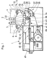
棒状体(ストランド)形成装置1には、横方向方法で作動するグループ形成装置2が付設されている。このグループ形成装置は2つの貯蔵容器3,4を備えている。この貯蔵容器内には、第1または第2の種類のフィルタロッド6,7が入れられている。貯蔵容器3,4の下側の端部、すなわち出口側の端部には、取り出しドラム8または9が設けられている。この取り出しドラムにはそれぞれ1個の切断装置11,12が付設されている。この切断装置は貯蔵容器3,4から取り出されたフィルタロッド6または7を切断する。その後にそれぞれ段状化ドラム13または14が設けられている。切断されたフィルタロッド6または7によって形成されたフィルタ部分は、段状化ドラム上で段状になり、続いて各々1個のスライドドラム16または17によって、横軸方向に連続して列をなすようにスライドさせられる。このようにして形成されたフィルタ部分の列は続いて、加速ドラム18または19によって互いに引き離されるので、個々のフィルタ部分の間に大きな間隔が生じる。
The rod-shaped body (strand) forming
その後で、フィルタ部分は切断ドラム21または22でもう一度切断される。この切断ドラムには同様に、各々1個の切断装置23または24が付設されている。再度切断されたフィルタ部分は切断ドラム21または22上で同時に新たに互いに引き離されるので、個々の要素の間に大きな隙間が生じる。次に、この隙間内に、他の種類のフィルタロッドの要素が編成ドラム26上で挿入され、これによりフィルタロッドグループ27が形成される。このフィルタロッドグループは異なる種類のフィルタの複数の要素からなっている。フィルタロッドグループ27は続いて、移送装置または方向変更ドラム28の形をした排出手段によって搬送方向に対して縦軸方向に向けられ、隙間のない形で、ボビン29から引き出された、棒状体形成装置1の被覆帯31上に連続的に移送される。この移送は例えばドイツ連邦共和国特許出願公開第2534666号公報に従って行われる。
Thereafter, the filter part is cut once again with the cutting
フィルタロッドグループ27を被覆帯31上に下ろす前に、被覆帯は糊付けされる。そのために、糊貯蔵容器33と2個の塗布ノズル34,36を備えた第1の糊付け装置32が設けられている。この第1の糊付け装置は、並んで平行に延びる2つの糊帯の形をした内側糊付け部を、被覆帯31上に形成する。糊貯蔵容器38と糊塗布ノズル39からなる第2の糊付け装置37は、継目糊付けのために被覆帯31のエッジ範囲に糊帯を付ける。勿論、内部糊付けのために、必要ときには1つの糊帯または2つよりも多い糊帯を設けることができる。
Before the
或る用途では、第1の糊付け装置32の糊貯蔵容器33が低温糊を含み、第2の糊付け装置37の貯蔵容器38が高温溶融接着剤を含んでいる。この用途の場合、方向変更ドラム28の降ろし範囲41内において被覆帯31の下方に、加熱装置43の形をした内側糊付け部を固化する手段42が設けられている。この加熱装置により、糊塗布ノズル34,36によって塗布された内側糊付け部が、フィルタロッドグループ27を降ろした後すぐに固化し、それによってフィルタロッドグループ27が被覆帯31に降ろした後すぐに固定されるので、フィルタロッドグループは例えば後続のフィルタロッドグループによる外部からの作用によって位置がずれることない。
In some applications, the
同時に、加熱装置43は継目糊付けのための高温溶融接着剤を活性化(溶融)する。これによって隙間のない列をなすように固定されたフィルタロッドグループ27は続いて、フォーマット室44の形をした成形部分を通過する。このフォーマット室内では、被覆帯31がフィルタロッドグループ27の周りに巻付けられるので、連続的なフィルタ棒状体が形成される。この場合、糊塗布ノズル39によって塗布された継目糊付けのための高温溶融接着剤は接着室46内で固化される。そのために、この接着室は冷却装置47として形成されている。これによって閉鎖および封止されたフィルタ棒状体は続いて切断装置48に達する。この切断装置では、好ましくは使用長さの複数倍の長さの組合せフィルタロッド49が切断される。この組合せフィルタロッドはそれぞれ、異なる種類のフィルタロッド6,7のフィルタ要素を含んでいる。
At the same time, the
マルチセグメントフィルタを製造するためにフィルタセグメントのグループを編成するための本発明による装置を備えた本発明によるマルチセグメントフィルタ製造装置が図2に示してある。棒状体形成装置1は本質的に図1の棒状体形成装置1に一致している。この場合、図2には更に、棒状体切り取り装置50が示してある。この棒状体切り取り装置によって、棒状体形成の開始時に、フィルタ棒状体をすぐに切り取ることができる。この切り取りは被覆材料によるフィルタセグメントの被覆が正しく規定通りに行われることによって達成される。切り取られたフィルタ棒状体はシュートを経てごみ容器56内に達する。棒状体形成装置1には更に、押し込みドラム57が示してある。n倍の使用長さ、例えば2倍、4倍または6倍の使用長さのフィルタが、他の加工、特にたばこ棒に取り付けるために、押し込みドラム57によって他の機械に押し込まれる。
A multi-segment filter manufacturing apparatus according to the present invention comprising an apparatus according to the present invention for organizing a group of filter segments to produce a multi-segment filter is shown in FIG. The bar-shaped
図2には更に、本発明によるマルチセグメントフィルタを製造するためにフィルタセグメントのグループを編成するための装置が示してある。このフィルタセグメントのグループを編成するための装置は、グループ形成装置でもある。この場合、独立した機能ユニット604,605.1,605.2,61.1が使用される。機能ユニット604は、2つの個々のフィルタセグメントを供給する軟質要素ユニットである(図4a)。機能ユニット605.1,605.2は、2倍の使用長さの個々のフィルタプラグまたは個々のフィルタセグメントを供給する軟質要素ユニットである。機能ユニット61.1は硬質要素ユニットである。機能ユニット内にはそれぞれ貯蔵容器53.1〜53.3,54.1が設けられている。この場合、勿論、軟質要素ユニット605.1,605.2または604の場合には、軟質要素貯蔵容器53.1〜53.3が設けられ、硬質要素ユニット61.1には硬質要素貯蔵容器54.1が設けられている。軟質要素ユニット604,605.1,605.2では、例えば酢酸セルロースまたはフリースからなる軟質セグメントまたはソフト要素が加工され、加工されたセグメントはドラム上に降ろされる。これに対して、硬質要素ユニット61.1では、焼結された顆粒、顆粒を充填したチューブまたは空のチューブのような硬質要素がドラム上で位置決めされる。グループ形成装置2または独立した機能ユニットには、エネルギー供給ユニット58によってエネルギーが供給される。
FIG. 2 further shows an apparatus for organizing groups of filter segments to produce a multi-segment filter according to the present invention. The device for organizing this group of filter segments is also a group forming device. In this case, independent
図2のマルチセグメントフィルタ製造装置によって、例えば、4個のフィルタ要素を有する紙巻たばこ用のマルチセグメントフィルタが製造可能である。 A multi-segment filter for cigarettes having, for example, four filter elements can be manufactured by the multi-segment filter manufacturing apparatus of FIG.
例えば2倍の使用長さのソフト要素が編成ドラム64.2(図5a参照)のトラフ84の中央に配置される。そして、2倍の使用長さのこのソフト要素の周りに硬質要素を隣接配置することができる。更に、機能ユニット604によって、2個のソフト要素を上記硬質要素の外側に配置することができる。最後に、移送ユニット62に最も接近して配置された機能ユニット605.2によって、2倍の使用長さの他のソフト要素が、フィルタ要素のグループの左側と右側で、移送ドラム63.6または編成ドラム64.2のそれぞれのトラフ内に横軸線方向に一列に並ぶように配置される。このようにして形成されたフィルタ要素のグループは、ボビンホルダー30に取付けられた図2に示していないボビン29から来る被覆紙によってマルチフィルタ棒状体を形成するために、移送ユニット62に移送され、それ自体公知の方向変更ドラム28によって棒状体形成装置の搬送手段上に縦軸線方向に降ろされる。そのために、標準フィルタ被覆紙を使用することができる。
For example, a double-use soft element is arranged in the center of the
本発明は、特に、新規なグループ形成装置2に関する。このグループ形成装置は、本出願人のKDFと組み合わせてフィルタ製造ラインを形成する。多重フィルタを製造可能である。この多重フィルタは4倍または6倍の長さのフィルタロッドとして、本出願人のフィルタ装着機MAXにおいてたばこ棒と共に加工されてフィルタ付き紙巻たばこを形成する。
The present invention particularly relates to a novel
図3には、図2に対する本発明の変形または他の実施形態が示してある。図3では、図2の左側に配置された軟質要素ユニット604,605.2の間に更に、硬質要素ユニット61.2が配置されている。例えば異なる5個のセグメントを含む、紙巻たばこ用多重フィルタを製造することができる。
FIG. 3 shows a variation or other embodiment of the invention relative to FIG. In FIG. 3, a hard element unit 61.2 is further arranged between the
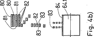
図4a)には、本発明による軟質要素ユニット604が概略的に示してある。この軟質要素ユニットによって2個のフィルタセグメントが供給される。軟質要素貯蔵容器53.1には、例えば酢酸セルロースからなる軟らかいフィルタロッド80が供給要素70.1を経て供給される。取り出しドラム8.1を介して、例えば8倍の使用長さのフィルタロッドまたはフィルタ要素80が取り出される。フィルタ要素80を確実に取り出すために、はねのけローラ71.1が設けられている。貯蔵装置から棒状品物を取り出すための装置は例えばドイツ連邦共和国特許第2505998号公報(米国特許第4020973号明細書に対応する)によって公知である。
FIG. 4a) schematically shows a
フィルタセグメント80は取り出しドラム8.1上で、回転駆動される第1の円形カッター72.1によって、4倍の使用長さを有する2個のフィルタ要素81に切断される。この円形カッターは研磨要素73.1で研磨される。そして、他の2個の円形カッター72.2によって他の2個所の切断が行われる。この円形カッターは前後に配置され、図4a)ではそのうちの前側の円形カッターだけが見える。この切断により、フィルタ要素81は2倍の使用長さの全部で4個のフィルタ要素82に分割される。
The
そして、取り出しドラム8.1上に縦軸方向に配置された4個のフィルタ要素82が段状化ドラム13.1に移送される。この段状化ドラムによって、フィルタ要素82は、図4b)に示すように、段状に配置される。次に、スライド/切断ドラム74.1への移送が行われる。このスライド/切断ドラムでは、最初に、フィルタ要素82の横軸方向の整列が行われる。次に、フィルタ要素は円形カッター72.3によって2個のフィルタプラグ83に切断される。このようにして切断されたフィルタプラグ83は、移送ドラム63.4に移送される。それによって、スライド/移送ドラム75.1に移送することができる。このスライド/移送ドラムでは、フィルタプラグ83が互いに離される。離されたフィルタプラグ83は編成ドラム64.1に移送され、そして移送ドラム63.5に移送される。この移送ドラムは、他の機能ユニットの編成ドラム64.2〜64.5に作用連結可能である。それによって、移送ドラム63.5に降ろされたフィルタ要素は、他の編成ドラム64.2〜64.5に降ろされたフィルタ要素と組み合せられる。
Then, four
図4cは、軟質要素ユニット604の本発明による他の実施形態を概略的に示している。この軟質要素ユニットは、大きさと全体構造が図4a)の軟質要素ユニットと一致しているが、若干のドラムが異なるように形成されている。図4a)の軟質要素ユニットで配置されたドラム74.1,63.4は、スライド/切断/スライドドラム90.1によって置き換えられている。更に、スライド移送ドラム75.1は移送ドラム63.11によって置き換えられている。
FIG. 4 c schematically shows another embodiment of the
スライド/切断/スライドドラム90.1は、図7,8を参照して後述するスライド/切断/スライドドラム90にほぼ一致している。図4dに示したフィルタ要素80〜83は、段状化ドラム13.1までは図4a)と同様に加工される。段状化ドラム13.1は2倍の使用長さのフィルタ要素82を段状にずらし、このフィルタ要素をスライド/切断/スライドドラム90.1に移送する。このスライド/切断/スライドドラムでは、2倍の使用長さのフィルタ要素が、最初に横軸方向に整列され、そして切断され、更に縦軸方向に互いに離される。それによって、続いて、切断されたフィルタプラグ83を縦軸方向に所定の間隔をおいて移送ドラム63.11に移送することができる。この移送ドラム自体は、フィルタプラグを再び編成ドラム64.1の収容トラフ84に移送する。移送ドラムは場合によっては、幾何学的に幾分異なる構造の場合、この実施例から取り除くことができるので、軟質要素ユニット604の構造高さは低くなる。
The slide / cut / slide drum 90.1 substantially corresponds to the slide / cut /
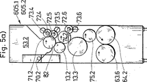
図5a)には、本発明による機能ユニット605.1または605.2の他の実施例が概略的に示してある。この機能ユニット605.1または605.2によって、2倍の使用長さの個々のフィルタプラグが供給される。図4a)の機能ユニット604との違いは、下流側の移送ドラム63.4の代わりに、段状化ドラム13.3が設けられていることにある。この段状化ドラムによって、切断されたフィルタプラグ83が段状にずらされてスライド/移動ドラム75.2に移送される。従って、スライド/移動ドラム75.2のトラフまたはこのユニットに付設された編成ドラム64.2と移送ドラム63.6のトラフ毎に、最大で1つだけのフィルタプラグ83が配置される。図5b)と図4b)には、更に、編成ドラム64.1または64.2の収容トラフ84が概略的に示してある。図5a)の機能ユニットによって、好ましくは、マルチセグメントフィルタの最初と最後のフィルタセグメントが挿入される。機能ユニット605.2の場合、編成ドラム64.2と移送ドラム63.6上に、前もって挿入されたすべてのフィルタプラグ83,87が配置され、2倍の長さを有する供給された新しいフィルタプラグ83は、フィルタセグメントグループの片側に装着される。
FIG. 5 a) schematically shows another embodiment of the functional unit 605.1 or 605.2 according to the invention. With this functional unit 605.1 or 605.2, individual filter plugs of twice the working length are supplied. The difference from the
図6a)には、本発明による硬質要素ユニット61.1〜61.3が示してある。硬質要素貯蔵容器54.1から2つの供給ダクト86.1,86.2を経て、硬質フィルタ要素87が2個の取り出しドラム8.3,8.4に供給される。そのために、図6a)に概略的に示すように、供給ダクト86.1,86.2は可動である。それによって、硬質フィルタ要素87を取り出しドラム8.3,8.4にできるだけやさしく移送することができる。取り出しドラム8.3,8.4は、多数の要素を迅速に移送することができるように形成可能である。これに関して、特に、本出願人の特許出願であるドイツ連邦共和国特許出願第10146992.6号、発明の名称“移送装置とトラフドラム並びに紙巻たばこ要素の移送方法”が参照される。この本出願人の上記出願の内容は、全部が本出願に含まれる。
FIG. 6a) shows rigid element units 61.1 to 61.3 according to the invention. The
図6b)に示すように段状にされて移送された硬質フィルタ要素87は、スライドドラム16.1,16.2に移送される。このスライドドラムでは、硬質フィルタ要素87が連続する収容トラフ内に横軸方向に配置される。横軸方向に並べて配置された硬質フィルタ要素は、移送ドラム63.8を経てこのユニットの編成ドラム64.3に移送され、そして移送ドラム63.7を経て移送される。
The
図7は、本発明による軟質要素ユニット604または605.1〜605.6の一部の概略的な平面図である。この場合、特に、本発明による軟質要素ユニット604または605.1〜605.6の中央要素は、スライド/切断/スライドドラム90によって示してある。フィルタ要素82、例えば2倍の使用長さのフィルタ要素は、段状化ドラム13.4によって段状にされて位置a)でドラム90に移送される。そして、ドラム90の運動方向において、移送されたフィルタ要素82は、横軸方向に並ぶように収容トラフ84内で位置決めされる。そのために、トラフシール92.1が設けられている。このトラフシールは、例えばフィルタ要素の位置をずらすために、フィルタ要素を保持する吸気を遮断するときに、フィルタ要素82の落下を防止する。このプロセスは位置b)で行われる。
FIG. 7 is a schematic plan view of a portion of a
位置c)では、円形カッター72.7によってそれぞれのフィルタ要素82が2個のフィルタプラグ83に切断される。両フィルタプラグ83は、位置d)において互いに離される。そのために、フィルタプラグを保持する吸気の一部が遮断されるので、この個所でもトラフシール92.2が必要である。位置e)では、フィルタプラグ83が編成ドラム64.4に移送され、場合によっては既にその上にある他のフィルタプラグまたはフィルタ要素と組み合せられる。
In position c), each
図8には、本発明によるスライド/切断/スライドドラム90の機能が示してある。異なる位置a)〜e)において、それぞれプロセスにとって重要な要素が示してある。図8a)では、段状にされたフィルタ要素82が収容トラフ84に移送される。そして、吸気が図8b)において左側からフィルタ要素82に作用するので、フィルタ要素は、左側のストッパー93.1または93.2まで左側に移動する。吸気による作用の代わりに、スライド要素88を使用してもよい。このスライド要素は、図8ではなく、例えば図9に示してある。フィルタ要素82は、横軸方向に並んで収容トラフ84内に存在する。
FIG. 8 shows the function of the slide / cut /
位置c)において、左側のストッパー93.1または93.2は、円形カッター72.7によって切断を行うために、フィルタ要素82から少しだけずらされる。この切断によって、フィルタプラグ83が形成される。
In position c), the left-hand stopper 93.1 or 93.2 is shifted slightly from the
位置d)において、要素の間に吸気を作用させることによって、要素が互いに離れるので、両フィルタプラグ83は左側と右側で両ストッパー93.1,93.2と94.1,94.2に接触する。位置e)では、ストッパーがフィルタプラグ83から左側と右側へ少しだけ離れるので、フィルタプラグは他のドラムに自由に移送可能である。
In position d), the elements are separated from each other by applying an air intake between the elements, so that both filter plugs 83 contact both stoppers 93.1, 93.2 and 94.1, 94.2 on the left and right sides. To do. In position e), the stopper is slightly separated from the
図9は、本発明によるスライド/切断/スライドドラム90の異なる位置a)〜e)の概略的な半分の断面図である。位置a)では、フィルタプラグ82は段状にされて前後に並んでいる。左側に配置されたフィルタ要素82は、断面が示され、右側に配置されたフィルタ要素82は上から見た状態が示してある。フィルタ要素82は、空気穴106,107からの吸気によって収容トラフ84内に保持される。吸気は、空気制御体98によってドラム90の回転位置に応じて制御される。この位置で、4つの空気穴106,107とフライス加工部100を経て空気出口99へ吸引が行われる。吸気の方向は、矢印によって示してある。ドラム90は軸102を介して運動する。この軸は、ボールベアリング101とニードルベアリング103を介して軸受されている。更に、スワッシュプレート97.1または97.2が示してある。このスワッシュプレートには、左側と右側のストッパー93.1または93.2、94.1または94.2が取付けられている。スワッシュプレートの運動は、カム109を介して制御され、このカムは、トルク支持体96によって支持される。
FIG. 9 is a schematic half sectional view of the different positions a) to e) of the slide / cut /
位置b)には、本発明によるドラム90の半分の断面が概略的に示してある。この場合、フィルタ要素82が横軸方向に並べて配置されている。更に、スライド要素88が概略的に示してある。このスライド要素によって、前側のフィルタ要素の後側に配置されたフィルタ要素が前側のフィルタ要素と一直線に並ぶ位置までスライドさせられる。概略的に示したスライド要素88の代わりに、図8bに示すように、吸気によってスライドさせることができる。この場合、スライド要素は不要である。これは、簡単にするために図示していない代替的な実施形態である。
In position b), a half section of a
図9の位置b)では、フィルタ要素82が、左側に配置した空気穴106,107を経て吸気によって左側から吸引される。これによって、フィルタ要素82は、左側のストッパー93.1に接触するように移動する。そのために、残りの空気穴106は、空気制御体98によって閉鎖されている。フィルタ要素がトラフから落下しないようにするために、トラフシール92,1が設けられている。このトラフシール92.1は、右側に、大気に通じる開口110またはフライス加工部110を備えている。それによって、フィルタ要素を左側に吸引する際に、右側に負圧が発生しない。これは、フィルタ要素の左側への移動を妨げない。
In position b) in FIG. 9, the
図9の位置c)では、左側のストッパーが幾分左側に移動している。従って、カッター溝104に係合する円形カッター72.7によって切断を行うことができる。その際、左側に配置したフィルタ要素が押しつぶされない。この位置では、フィルタ要素82または切断されたフィルタプラグ83は、再び吸気によって保持される。
In position c) in FIG. 9, the left stopper has moved somewhat to the left. Accordingly, the cutting can be performed by the circular cutter 72.7 engaged with the
図9の位置d)では、切断されたフィルタプラグ83が互いに離れるように移動する。そのために、トラフの左側とトラフ84の右側に、それぞれの空気穴106,107を経て吸気が作用する。互いに離れるように移動するフィルタプラグの間に負圧が生じないようにするために、左側に配置されたフィルタプラグ83の右側の範囲において、空気穴108がトラフシール92.2に設けられている。
In position d) in FIG. 9, the cut filter plugs 83 move away from each other. Therefore, intake air acts on the left side of the trough and the right side of the
図9の位置e)では、最初に、それぞれのストッパー93.1または93.2と94.1または94.2がフィルタプラグ83から離れるように移動する。それによって、フィルタプラグは、編成ドラム64.4に移送可能である。
In position e) in FIG. 9, first, the respective stoppers 93.1 or 93.2 and 94.1 or 94.2 are moved away from the
本発明によるドラムによって、特にフィルタプラグが、整列、切断および拡開される。これにより、例えば図4a)に概略的に示した下流側に設けられたドラム74.1,63.4および75.1が1個のドラム90によって置き換え可能である。従って、本発明による機能ユニットは非常に省スペース的に構成される。
By means of the drum according to the invention, in particular the filter plug is aligned, cut and expanded. Thereby, for example, the drums 74.1, 63.4 and 75.1 provided on the downstream side schematically shown in FIG. 4a) can be replaced by one
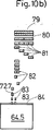
図10a)には、本発明による軟質要素ユニット605.3の他の実施形態が概略的に示してある。この軟質要素ユニットによって、2個のフィルタセグメント83が編成ドラム64.5に供給される。軟質要素貯蔵容器53.4には、例えば酢酸セルロースからなるフィルタロッドのような軟質フィルタロッド79が、供給要素70.3を経て入れられる。取り出しドラム8.5によって、例えば16倍の使用長さのフィルタロッド、すなわちフィルタ要素79が取り出される。フィルタ要素79の確実な取り出しのために、はねのけローラ71.3が設けられている。
FIG. 10a) schematically shows another embodiment of the soft element unit 605.3 according to the invention. Two
フィルタ要素79は、取り出しドラム8.5上で、1個の第1円形カッター72.8と2個の第2円形カッター72.9によって4倍の使用長さの4個のフィルタ要素81に切断される。この円形カッターは、それぞれ研磨手段73.8,73.9によって常時研磨される。そして、切断されたフィルタ要素81が段状化ドラム13.5に移送されるので、フィルタ要素は、図10b)に示すように段状化ドラム13.5上で段状にされて配置される。これに続くスライド/切断/スライドドラム74.3では、最初に段状にされたフィルタ要素81が横軸方向に並ぶようにスライドさせられる。それによって、フィルタ要素は、回転運動する他の円形カッター72.10によってそれぞれ2倍の使用長さの2個のフィルタ要素82に切断可能である。このフィルタ要素は、段状にされて段状化ドラム13.4に移送される。そして、本発明によるスライド/切断/スライドドラム90が続く。このスライド/切断/スライドドラムによって、2倍の使用長さのフィルタ要素82は、1倍の使用長さのフィルタ要素83に切断され、互いに離される。それによって、編成ドラム64.5に移送することができる。編成ドラム64.5に続いて、移動ドラム63.9が配置されている。この移送ドラムには、フィルタ要素83が移送される。
The
図11は、棒状体形成装置と他のグループ編成装置とを備えたマルチセグメントフィルタ製造装置の概略的な側面図である。図2,3に示した編成ドラム64.1〜64.5と、この編成ドラムに作用連結された移送ドラム63.5,63.6,63.7,63.9の代わりに、コンベヤベルト120が設けられている。このコンベヤベルトは、この例では、図示した4個の機能ユニット605.4〜605.6,61.3にわたって延設されている。マルチセグメントフィルタの製造の要望に応じて、軟質要素と硬質要素が種々のドラムを介して機能要素605.4〜605.6,61.3内で加工され、搬送され、そして適合した移送ドラムによってコンベヤベルト120に載せられる。この場合、フィルタセグメントは、収容トラフ131に降ろされる。1本のコンベヤベルト120または多数のコンベヤベルト120.1〜120.3は、駆動輪121と方向転換輪122を経て搬送方向130に移動する。フィルタセグメントをコンベヤベルト120の収容トラフ内に保持するために、真空箱123が設けられている。この真空箱の機能について、次に図12,13を参照して詳しく説明する。
FIG. 11 is a schematic side view of a multi-segment filter manufacturing apparatus including a rod-shaped body forming apparatus and another group knitting apparatus . Instead of the knitting drums 64.1 to 64.5 shown in FIGS. 2 and 3 and the transfer drums 63.5, 63.6, 63.7, 63.9 operatively connected to the knitting drum, the
マルチセグメントフィルタまたはダブルマルチセグメントフィルタのためのすべてのフィルタセグメントを降ろした後で、このフィルタセグメントは、移送ドラム63.10と他の移送ドラム63.11によって、それ自体公知の方向変更ドラム28に移送される。それによって、その後の縦軸方向のプロセスにおいて、例えば本出願人の公知のKDF機械によって、被覆材料を先行するフィル棒状体の周りに当てがうことができる。更に、清掃箱124を設けることができる。この清掃箱によって、コンベヤベルト120またはコンベヤベルト120.1〜120.3を清掃することができ、しかもフィルタ要素がトラフ内に設けられていない位置で清掃することができる。そのために、例えば吹き付け空気を使用することができる。
After lowering all filter segments for a multi-segment filter or a double multi-segment filter, this filter segment is transferred by a transfer drum 63.10 and another transfer drum 63.11 to a
図12a)と図12b)には、フィルタセグメントの装着方法が概略的に示してある。この場合、それに関連する真空箱123が図12b)に示してある。最初に、コンベヤベルト120が搬送方向130に移動する。図12a)には真空穴132が示してある。この真空穴を経て真空が作用するときに、フィルタセグメント83.1〜83.4は、真空穴132上のその位置に保持される。位置Aは、軟質要素ユニット605.6がフィルタ要素83.1をコンベヤベルトのほぼ中央で収容トラフ131に降ろしている位置に相当する。その後で、2個の硬質要素83.2がBのところで硬質要素ユニット61.3の範囲においてコンベヤベルト上に降ろされる。続いて、第1のスライド要素134によって、フィルタ要素83.1,83.2が互いに寄せられる。続いて、2個の軟質フィルタ要素83.3が既に降ろされたフィルタ要素の外側に降ろされ、しかも軟質要素ユニット605.5内においてかつ位置Cで降ろされる。この軟質要素はスライド要素135によってその前に降ろされたフィルタ要素に押し付けられる。最後に、他の軟質要素83.4が軟質要素ユニット605.4において左側から位置Dで降ろされ、続いてスライド要素136によって互いに寄せられる。従って、フィルタロッドグループ27が生じる。
FIGS. 12a) and 12b) schematically show how the filter segments are mounted. In this case, the associated
図12b)には、真空箱123の真空穴133.1の配置構造が概略的に示してある。この場合、関連する収容トラフ131の若干の真空穴132が図示のため一緒に記入されている。真空穴133.1が搬送方向に拡大し、しかも、それぞれ降ろされたフィルタ要素83.1〜83.4に真空が作用するように真空穴が形成されていることがはっきりと判る。
FIG. 12 b) schematically shows the arrangement structure of the vacuum holes 133.1 of the
1個のコンベヤベルト120または図13a)に示すように6個のコンベヤベルト120.1〜120.6へのフィルタ要素の供給の他の実施形態が図13a),13b)に示してある。このフィルタ要素の供給の際、最初に、外側に位置するフィル要素が降ろされ、最後に内側に位置するフィルタ要素が降ろされる。最後に、スライド要素137によって、降ろされたフィルタ要素を寄せることにより、フィルタロッドグループ27となる。図13b)には、真空穴133.2が示してある。この真空穴は、コンベヤベルトのフィルタ装着方法を可能にする。
Another embodiment of supplying filter elements to one
搬送ドラムの代わりにコンベヤベルトを使用する利点は、連続的な搬送に基づいて、半径方向の力がフィルタセグメントに作用しないので、非常にやさしい搬送を行うことができることにある。更に、移送が少なく、必要な空気圧の出し入れが少ないので、装置の騒音が小さい。製造材料が操作人の見える範囲にあるので、故障をきわめて迅速に認識することができる。 The advantage of using a conveyor belt instead of a transport drum is that, based on continuous transport, radial forces do not act on the filter segments, so that very easy transport can be achieved. Furthermore, since the transfer is small and the required air pressure is little, the noise of the device is small. Since the production material is within the range of the operator's view, the failure can be recognized very quickly.
マルチセグメントフィルタを製造するためのフィルタセグメントのグループを編成するための装置において独立した機能ユニットを使用することにより、例えば硬質要素を使用する際に、複数のモジュールを使用することによって生産能力を上昇させることができる。更に、軟質モジュールまたは軟質要素ユニットだけを使用すると、高い生産能力が可能である。特に、マルチセグメントフィルタ毎に2〜5個のフィルタセグメントが製造可能である。適当な顆粒は、好ましくは規格化されて硬質要素で使用される。 Increased production capacity by using multiple modules, for example when using rigid elements, by using independent functional units in an apparatus for organizing groups of filter segments to produce multi-segment filters Can be made. Furthermore, a high production capacity is possible if only soft modules or soft element units are used. In particular, 2 to 5 filter segments can be produced for each multi-segment filter. Suitable granules are preferably standardized and used in rigid elements.
本発明による装置によって、必要な機械コストが少なくて済む。更に、機能のリスクが小さい。というのは、特に公知の連続方法あるいは例えばドイツ連邦共和国特許出願公開第2452749号公報に記載され、本出願人の連続機械KDFにおいて使用される方法のように、公知の方法が若干のプロセスで適用されるからである。
The device according to the invention requires less machine costs. Furthermore, the risk of function is small. This is because, in particular, the known methods can be applied in some processes, such as the known continuous methods or the methods used in the Applicant's continuous machine KDF, for example as described in
1 棒状体形成装置
2 グループ形成装置
3 貯蔵容器
4 貯蔵容器
6 フィルタロッド
7 フィルタロッド
8 取り出しドラム
8.1〜8.5 取り出しドラム
9 取り出しドラム
11 切断装置
12 切断装置
13 段状化ドラム
13.1〜13.6 段状化ドラム
14 段状化ドラム
16 スライドドラム
16.1,16.2 スライドドラム
17 スライドドラム
18 加速ドラム
19 加速ドラム
21 切断ドラム
22 切断ドラム
23 切断装置
24 切断装置
26 編成ドラム
27 フィルタロッドグループ
28 方向変更ドラム
29 ボビン
30 ボビンホルダー
31 被覆帯
32 糊付け装置
33 糊貯蔵容器
34 塗布ノズル
36 塗布ノズル
37 糊付け装置
38 貯蔵容器
41 降ろし範囲
42 固化手段
43 加熱装置
44 成形室
46 接着室
47 冷却装置
48 切断装置
49 組合せフィルタロッド
50 棒状体切り取り器
53.1〜53.4 軟質要素貯蔵容器
54.1,54.2 硬質要素貯蔵容器
56 くず容器
57 押し込みドラム
58 エネルギー供給ユニット
604 軟質要素ユニット
605.1,605.6 軟質要素ユニット
61.1〜61.3 硬質要素ユニット
62 移送ユニット
63.1〜63.11 移送ドラム
64.1〜64.5 編成ドラム
70.1〜70.3 供給要素
71.1〜71.3 はねのけローラ
72.1〜72.10 円形カッター
73.1〜73.10 研磨要素
74.1〜74.3 スライド/切断ドラム
75.1,75.2 スライド/移送ドラム
79 フィルタ要素(16倍)
80 フィルタ要素(8倍)
81 フィルタ要素(4倍)
82 フィルタ要素(2倍)
83 フィルタプラグ
83.1〜83.4 フィルタ要素
84 収容トラフ
86.1,86.2 供給ダクト
87 硬質フィルタ要素
88 スライド要素
90・90.1 スライド/切断/スライドドラム
92.1 トラフシール
93.1,93.2 左側ストッパー
94.1,94.2 右側ストッパー
96 トルク支持部
97.1,97.2 スワッシュプレート
98 空気制御体
99 空気出口
100 フライス加工部
101 ボールベアリング
102 軸
103 ニードルベアリング
104 カッター溝
106 空気穴
107 空気穴
108 空気穴
109 カム
110 フライス加工部
120 コンベヤベルト
120.1〜120.3 コンベヤベルト
121 駆動輪
122 方向変換輪
123 真空箱
124 清掃箱
130 搬送方向
131 トラフ
132 真空穴
133.1,133.2 真空穴
134 スライド要素
137 スライド要素
DESCRIPTION OF SYMBOLS 1 Bar-shaped body formation apparatus 2 Group formation apparatus 3 Storage container 4 Storage container 6 Filter rod 7 Filter rod 8 Extraction drum 8.1-8.5 Extraction drum 9 Extraction drum 11 Cutting apparatus 12 Cutting apparatus 13 Staged drum 13.1 ˜13.6 Stepped drum 14 Stepped drum 16 Slide drum 16.1, 16.2 Slide drum 17 Slide drum 18 Acceleration drum 19 Acceleration drum 21 Cutting drum 22 Cutting drum 23 Cutting device 24 Cutting device 26 Knitting drum 27 Filter rod group 28 Direction changing drum 29 Bobbin 30 Bobbin holder 31 Covering band 32 Gluing device 33 Glue storage container 34 Coating nozzle 36 Coating nozzle 37 Gluing device 38 Storage container 41 Lowering range 42 Solidifying means 43 Heating device 44 Molding chamber 46 Bonding chamber 47 Cooling device 48 Cutting equipment 49 Combined filter rod 50 Rod-like body cutter 53.1-53.4 Soft element storage container 54.1, 54.2 Hard element storage container 56 Waste container 57 Push drum 58 Energy supply unit 604 Soft element unit 605.1, 605 .6 Soft element unit 61.1 to 61.3 Hard element unit 62 Transfer unit 63.1 to 63.11 Transfer drum 64.1 to 64.5 Knitting drum 70.1 to 70.3 Supply element 71.1 to 71 .3 Splash roller 72.1 to 72.10 Circular cutter 73.1 to 73.10 Polishing element 74.1 to 74.3 Slide / cut drum 75.1, 75.2 Slide / transfer drum 79 Filter element (16 times) )
80 filter elements (8 times)
81 Filter elements (4 times)
82 filter elements (double)
83 Filter plug 83.1 to 83.4
Claims (12)
装置が、グループ(27)を構成するフィルタセグメント(6,7,79,80〜83,83.1〜83.4,87)の種類に応じてそれぞれ使用可能な、それぞれモジュールとして形成された独立した多数の機能ユニット(604,605.1〜605.6,61.1〜61.3)を備え、独立した多数の機能ユニット(604,605.1〜605.6,61.1〜61.3)が一列に配置され、隣接する2つの機能ユニット(604,605.1〜605.6,61.1〜61.3)の搬送要素(8.1〜8.5,13.1〜13.6,16,16.1〜16.2,63.1〜63.10,64.1〜64.5,74.1〜74.3,75.1〜75.2,90)の少なくとも一部が、フィルタセグメント(6,7,79,80〜83,83.1〜83.4,87)のグループ(27)を編成するために作用連結されており、編成されたフィルタセグメント(6,7,79,80〜83,83.1〜83.4,87)が、移送装置(62)によって後続の棒状体形成装置(1)に引き渡されること、
作用連結可能な搬送要素が、付属する機能ユニットから、グループ(27)内の所定の位置で少なくとも1つのフィルタセグメント(6,7,79,80〜83,83.1〜83.4,87)を受け取る編成ドラム(64.1〜64.5)と、フィルタセグメント(6,7,79,80〜83,83.1〜83.4,87)をこの編成ドラム(64.1〜64.5)から隣の機能ユニット(604,605.1〜605.6,61.1〜61.3)の編成ドラム(64.1〜64.5)又は移送装置(62)に引き渡す移送ドラム(63.1〜63.10)であり、編成ドラム(64.1〜64.5)と移送ドラム(63.1〜63.10)が、互いに係合し、一列に水平に配置されており、これにより、各々の機能ユニット(604,605.1〜605.6,61.1〜61.3)から、フィルタセグメント(6,7,79,80〜83,83.1〜83.4,87)が搬送要素によって横軸方向に搬送され、グループ(27)が編成可能であることを特徴とする装置。Tobacco processing industry in a continuous manner, wherein each multi-segment filter (49) is provided with at least two different types of filter segments (6, 7, 79, 80-83, 83.1-83.4, 87) In an apparatus for organizing a group (27) of filter segments (6, 7, 79, 80-83, 83.1-83.4, 87) to produce a multi-segment filter (49) of
The device can be used according to the type of filter segments (6, 7, 79, 80 to 83, 83.1 to 83.4, 87) constituting the group (27), and is independently formed as a module. A plurality of functional units (604, 605.1 to 605.6, 61.1 to 61.3), and a large number of independent functional units (604, 605.1 to 605.6, 61.1 to 61.61) . 3) are arranged in a row, and the conveying elements (8.1 to 8.5, 13.1 to 13) of two adjacent functional units (604, 605.1 to 605.6, 61.1 to 61.3) 6, 16, 16.1 to 16.2, 63.1 to 63.10, 64.1 to 64.5, 74.1 to 74.3, 75.1 to 75.2, 90). Part is a filter segment (6, 7, 79, 80-83 Is coupled act to organize the group (27) of 83.1~83.4,87), filter segments (6,7,79,80~83,83.1~83.4 organized, 87) is transferred by the transfer device (62) to the subsequent rod-shaped body forming device (1) ,
At least one filter segment (6, 7, 79, 80 to 83, 83.1 to 83.4, 87) at a predetermined position in the group (27) from an associated functional unit from the associated functional unit. The knitting drum (64.1 to 64.5) for receiving the filter segment (6, 7, 79, 80 to 83, 83.1 to 83.4, 87) is connected to the knitting drum (64.1 to 64.5). ) From the next functional unit (604, 605.1 to 605.6, 61.1 to 61.3) to the knitting drum (64.1 to 64.5) or the transfer device (62). 1 to 63.10), and the knitting drum (64.1 to 64.5) and the transfer drum (63.1 to 63.10) are engaged with each other and arranged horizontally in a row. , Each functional unit (604, 60 .1 to 605.6, 61.1 to 61.3), the filter segments (6, 7, 79, 80 to 83, 83.1 to 83.4, 87) are conveyed in the horizontal axis direction by the conveying element. A device characterized in that the group (27) can be organized .
Applications Claiming Priority (3)
| Application Number | Priority Date | Filing Date | Title |
|---|---|---|---|
| DE10146019A DE10146019A1 (en) | 2001-09-18 | 2001-09-18 | Production machine for multi-segmented filters, has various operating units, conveyor elements as drums |
| DE10155292.0A DE10155292B4 (en) | 2001-09-18 | 2001-11-02 | Device for assembling groups of filter segments for the production of multi-segment filters of the tobacco-processing industry and hollow drum |
| PCT/EP2002/009746 WO2003024256A2 (en) | 2001-09-18 | 2002-08-31 | Device for combining groups of filter segments for producing multi-segment filters of the tobacco industry, and trough drum |
Publications (3)
| Publication Number | Publication Date |
|---|---|
| JP2005502376A JP2005502376A (en) | 2005-01-27 |
| JP2005502376A5 JP2005502376A5 (en) | 2006-01-05 |
| JP4630548B2 true JP4630548B2 (en) | 2011-02-09 |
Family
ID=26010174
Family Applications (1)
| Application Number | Title | Priority Date | Filing Date |
|---|---|---|---|
| JP2003528159A Expired - Fee Related JP4630548B2 (en) | 2001-09-18 | 2002-08-31 | Apparatus and trough drum for organizing groups of filter segments to produce multi-segment filters for the tobacco processing industry |
Country Status (10)
| Country | Link |
|---|---|
| US (1) | US8172739B2 (en) |
| EP (1) | EP1427299B2 (en) |
| JP (1) | JP4630548B2 (en) |
| CN (1) | CN1279855C (en) |
| AT (1) | ATE341231T1 (en) |
| AU (1) | AU2002333779A1 (en) |
| DE (3) | DE10146019A1 (en) |
| ES (1) | ES2269805T3 (en) |
| PL (2) | PL196669B1 (en) |
| WO (1) | WO2003024256A2 (en) |
Families Citing this family (86)
| Publication number | Priority date | Publication date | Assignee | Title |
|---|---|---|---|---|
| EP1397966A1 (en) | 2002-09-11 | 2004-03-17 | Hauni Maschinenbau AG | Apparatus and method for transforming rodlike filterelements |
| DE10344317A1 (en) * | 2003-09-19 | 2005-04-21 | Hauni Maschinenbau Ag | Distributor device for a machine of the tobacco processing industry |
| ITBO20030683A1 (en) * | 2003-11-17 | 2005-05-18 | Gd Spa | DRUM CENTERER FOR FILTER MACHINES |
| DE10354924B4 (en) | 2003-11-25 | 2024-01-18 | Körber Technologies Gmbh | Device for processing filter tow material and device for producing filters |
| DE102004017324B4 (en) * | 2004-04-06 | 2009-10-22 | Hauni Maschinenbau Ag | filter attachment |
| DE102005001186A1 (en) * | 2004-08-26 | 2006-03-09 | Universelle Engineering U.N.I. Gmbh | Filterzuführeinrichtung |
| CN1739414B (en) * | 2004-08-26 | 2012-07-18 | 环宇工程U.N.I.有限责任公司 | Apparatus for feeding filters |
| DE102004056718A1 (en) * | 2004-11-20 | 2006-06-01 | Hauni Maschinenbau Ag | Plug device for drive means and apparatus for producing rod-shaped products with a plurality of drive means |
| DE102004057445A1 (en) * | 2004-11-24 | 2006-06-01 | Hauni Maschinenbau Ag | Apparatus for contactless cleaning of a conveying element and arrangement for transporting and / or storing rod-shaped articles with a device for contactless cleaning of a conveying element |
| DE102004063097A1 (en) | 2004-12-22 | 2006-07-06 | Hauni Maschinenbau Ag | Module of a machine and method for perforating rod-shaped articles of the tobacco processing industry |
| DE102005000910B4 (en) * | 2005-01-06 | 2006-12-21 | Hauni Maschinenbau Ag | Production of filter stoppers or filter cigarettes |
| ITBO20050184A1 (en) * | 2005-03-24 | 2005-06-23 | Gd Spa | EQUIPMENT FOR THE PRODUCTION OF COMPOUND FILTERS |
| DE102005024645A1 (en) * | 2005-05-25 | 2006-11-30 | Hauni Maschinenbau Ag | Device for the preparation and / or production of rod-shaped objects of the tobacco-processing industry |
| ITBO20050448A1 (en) * | 2005-07-04 | 2007-01-05 | Gd Spa | SUPPLY UNIT FOR FILTERS TO A FILTER MACHINE |
| DE102005046581A1 (en) * | 2005-09-28 | 2007-03-29 | Hauni Maschinenbau Ag | Multi-segmented filters properties measuring device for tobacco processing industry, has laser light source forming line of electromagnetic radiation on filters, where extension of line is smaller than diameter of filters |
| ITBO20050696A1 (en) * | 2005-11-16 | 2007-05-17 | Gd Spa | MACHINE FOR THE PRODUCTION OF COMPOUND FILTERS |
| DE102006018111A1 (en) * | 2006-04-18 | 2007-10-25 | Hauni Maschinenbau Ag | Processing unit for processing at least one filter tow strip for the production of filters for rod-shaped smoking articles |
| ITBO20060720A1 (en) * | 2006-10-18 | 2008-04-19 | Gd Spa | MACHINE FOR THE PRODUCTION OF COMPOUND FILTERS. |
| ITBO20060719A1 (en) * | 2006-10-18 | 2008-04-19 | Gd Spa | MACHINE FOR THE PRODUCTION OF COMPOUND FILTERS. |
| DE102006060979B4 (en) * | 2006-12-20 | 2015-06-18 | Hauni Maschinenbau Ag | conveyor stabilizer |
| US7674218B2 (en) * | 2006-12-28 | 2010-03-09 | Philip Morris Usa Inc. | Filter component cutting system |
| DE102007002491B3 (en) * | 2007-01-11 | 2007-10-11 | Hauni Maschinenbau Ag | Cigarette manufacturing mechanical handling drum imparts longitudinal impulse during transfer to adjacent drum |
| DE102007028478B4 (en) | 2007-06-18 | 2015-03-05 | Hauni Maschinenbau Ag | Receiving device and conveying method |
| PL383995A1 (en) | 2007-12-10 | 2009-06-22 | Philip Morris Products S.A. | The manner of setting up a group of segments in multi-segment filter production process and a device for preparation and setting up in groups of segments in multi-segment filter production process |
| DE102008010659B3 (en) * | 2008-02-22 | 2009-07-30 | Hauni Maschinenbau Ag | Filter strand producing method for use in tobacco processing industry, involves arranging missing filter segments with filter segment group, and guiding segments into filter segment group, and bringing filter segment replacement element |
| DE102008020631B3 (en) | 2008-04-24 | 2009-08-20 | Hauni Maschinenbau Ag | Method for operating a machine of the tobacco processing industry and corresponding machine |
| IT1392375B1 (en) * | 2008-07-18 | 2012-03-02 | Gd Spa | PACKAGING MACHINE FOR THE PRODUCTION OF COMBINED FILTERS FOR CIGARETTES. |
| IT1392374B1 (en) | 2008-07-18 | 2012-03-02 | Gd Spa | PACKAGING MACHINE FOR THE PRODUCTION OF TOBACCO INDUSTRY ARTICLES. |
| DE102009015501B4 (en) | 2009-04-02 | 2011-03-31 | Hauni Maschinenbau Ag | Vacuum supply to a machine of the tobacco processing industry |
| DE102009017962A1 (en) | 2009-04-21 | 2010-11-04 | Hauni Maschinenbau Ag | Method and device for checking the quality of capsule filter rods |
| IT1395035B1 (en) * | 2009-08-10 | 2012-09-05 | Gd Spa | DOUBLE LINE MACHINE AND METHOD FOR THE CONSTRUCTION OF COMPOUND FILTERS FOR CIGARETTES, CIGARS OR THE LIKE. |
| DE102009041319A1 (en) | 2009-09-15 | 2011-03-24 | Hauni Maschinenbau Ag | Machine for manufacturing multi-segment filter in tobacco processing industry, during manufacturing of cigarettes, has cutting device comprising cutting drums, where one of drums cuts filter strands independent of other drum |
| DE102009041318A1 (en) * | 2009-09-15 | 2011-03-31 | Hauni Maschinenbau Ag | Inserting filter segments in filter strands |
| DE102009041320A1 (en) | 2009-09-15 | 2011-03-24 | Hauni Maschinenbau Ag | Machine for the production and method of manufacturing multi-segment filters of the tobacco processing industry |
| DE102009054801A1 (en) | 2009-12-16 | 2011-06-22 | HAUNI Maschinenbau Aktiengesellschaft, 21033 | Multi-segment filter manufacturing of the tobacco processing industry |
| US10299507B2 (en) | 2009-12-30 | 2019-05-28 | Philip Morris Usa Inc. | Compound horizontal filter assembly machine and process |
| DE102010002492A1 (en) * | 2010-03-02 | 2011-09-08 | Hauni Maschinenbau Ag | Conveyor drum of the tobacco processing industry |
| PL390871A1 (en) * | 2010-03-29 | 2011-10-10 | International Tobacco Machinery Poland Spółka Z Ograniczoną Odpowiedzialnością | Method for compensating temporary lack of filter sections in the production line of multi-section filters and a device for offsetting temporary lack of filter sections in the production line of multi-section filters |
| PL217430B1 (en) * | 2010-05-06 | 2014-07-31 | Int Tobacco Machinery Poland | Method for determining mutual position of the filter segments on the carrier element of the grouping unit in the process of manufacturing multi-segmented filters |
| DE102010042766A1 (en) | 2010-10-21 | 2012-04-26 | Hauni Maschinenbau Ag | Strand guiding device of a machine of the tobacco processing industry |
| DE102011006025B3 (en) | 2011-03-24 | 2012-07-19 | Hauni Maschinenbau Ag | Production of filter stoppers or filter cigarettes |
| US9055768B2 (en) | 2011-03-25 | 2015-06-16 | Hauni Maschinenbau Ag | High speed object inserter and related methods |
| US9232820B2 (en) * | 2011-03-25 | 2016-01-12 | Hauni Maschinenbau Ag | High speed object inserter and related methods |
| PL394455A1 (en) | 2011-04-06 | 2012-10-08 | International Tobacco Machinery Poland Spólka Z Ograniczona Odpowiedzialnoscia | Device for transmission of filter elements in the manufacturing process of multi-segment filters |
| DE102011017615A1 (en) * | 2011-04-27 | 2012-10-31 | Hauni Maschinenbau Ag | Method and device for placing objects in a material strand of the tobacco processing industry |
| EP2713781A2 (en) | 2011-06-03 | 2014-04-09 | Tobacco Research And Development Institute (Proprietary) Limited | Modular apparatus for smoking article manufacture |
| DE102011082592A1 (en) | 2011-09-13 | 2013-03-14 | Hauni Maschinenbau Ag | Filter rod loading device |
| DE102011113648A1 (en) | 2011-09-19 | 2013-03-21 | Hauni Maschinenbau Ag | Multifilterherstellmodul |
| RU2568520C2 (en) * | 2011-09-23 | 2015-11-20 | Пежо Ситроен Отомобиль Са | Protective panel to be secured at vehicle body part and vehicle with such panel |
| DE102011085981A1 (en) * | 2011-11-09 | 2014-01-09 | Hauni Maschinenbau Ag | Filter manufacturing machine of the tobacco processing industry |
| DE102012201279A1 (en) | 2012-01-30 | 2013-08-01 | Hauni Maschinenbau Ag | Method and apparatus for processing a wrapping material strip |
| DE102012206344B3 (en) * | 2012-04-18 | 2013-07-11 | Hauni Maschinenbau Ag | Device for compiling filter segment groups |
| DE102012207346A1 (en) | 2012-05-03 | 2013-11-07 | Hauni Maschinenbau Ag | Method and device for assembling filter segment groups |
| DE102012209032A1 (en) * | 2012-05-30 | 2013-12-05 | Hauni Maschinenbau Ag | Conveyor drum of the tobacco processing industry |
| DE102012106180A1 (en) | 2012-07-10 | 2014-01-16 | Hauni Maschinenbau Ag | Method for controlling a machine combination and / or a machine for processing rod-shaped articles of the tobacco-processing industry and a machine device therefor |
| DE102012213338B4 (en) * | 2012-07-30 | 2014-10-09 | Hauni Maschinenbau Ag | Method and device for producing multi-segment filter rods of the tobacco processing industry |
| DE102012215589A1 (en) | 2012-09-03 | 2014-03-06 | Hauni Maschinenbau Ag | Method and apparatus for processing a wrapping material strip |
| ITBO20120614A1 (en) * | 2012-11-08 | 2014-05-09 | Gd Spa | ASSEMBLY MACHINE FOR CIGARETTES PRODUCTION AND RELATIVE ASSEMBLY METHOD. |
| RU2643606C2 (en) | 2012-12-06 | 2018-02-02 | Бритиш Америкэн Тобэкко (Инвестментс) Лимитед | Installation for smoking product manufacture |
| DE102012224089A1 (en) | 2012-12-20 | 2014-06-26 | Hauni Maschinenbau Ag | Measuring arrangement and measuring method for a filter rod segment in the tobacco processing industry, machine for producing filter rods, machine and plant for the production of a multi-segment filter product |
| DE102013100815A1 (en) * | 2013-01-28 | 2014-07-31 | Hauni Maschinenbau Ag | A tray emptying device and method for automatically emptying trays filled with rod-shaped articles into a production machine of the tobacco-processing industry as well as a production arrangement with a production machine and at least two tray emptying devices |
| EP2798967B1 (en) * | 2013-05-02 | 2017-10-25 | Hauni Maschinenbau GmbH | Method for producing multi-segment filters for the tobacco-processing industry, and multi-segment filter manufacturing device |
| DE102013220757B3 (en) * | 2013-10-15 | 2015-01-15 | Hauni Maschinenbau Ag | Koaxialzigarettenherstellung |
| GB201321920D0 (en) * | 2013-12-11 | 2014-01-22 | British American Tobacco Co | A method and apparatus for inserting elongate elements into a sleeve |
| DE102013226296A1 (en) | 2013-12-17 | 2015-06-18 | Hauni Maschinenbau Ag | Filter segment handover |
| DE102014203620A1 (en) | 2014-02-27 | 2015-08-27 | Hauni Maschinenbau Ag | Method and apparatus for producing a strand of the tobacco processing industry |
| CN104770872A (en) * | 2015-02-12 | 2015-07-15 | 湖北中烟工业有限责任公司 | Multi-taste cigarette compounding device |
| DE102015110516A1 (en) | 2015-06-30 | 2017-01-05 | Hauni Maschinenbau Gmbh | Composing segments of the tobacco processing industry |
| DE102016100343A1 (en) * | 2016-01-11 | 2017-07-13 | Hauni Maschinenbau Gmbh | Method for producing a multi-segment filter and multi-segment filter manufacturing device of the tobacco processing industry |
| DE102016205630A1 (en) | 2016-04-05 | 2017-10-05 | Hauni Maschinenbau Gmbh | Receiving device and conveying method of the tobacco processing industry |
| GB201608810D0 (en) | 2016-05-19 | 2016-07-06 | British American Tobacco Co | Cutting and arranging rods for tobacco industry products |
| DE102016124052A1 (en) | 2016-12-12 | 2018-06-14 | Hauni Maschinenbau Gmbh | Filter segment assembly apparatus and method of assembling filter segments of the tobacco processing industry |
| DE102017106133A1 (en) | 2017-03-22 | 2018-09-27 | Hauni Maschinenbau Gmbh | Method for controlling a strand cutter and strand machine of the tobacco processing industry |
| DE102017114817A1 (en) | 2017-07-04 | 2019-01-10 | Tobias Becker | Filter segment transfer device and filter segment transfer method |
| DE102017117016A1 (en) | 2017-07-27 | 2019-01-31 | Hauni Maschinenbau Gmbh | Production of rod-shaped smoking products |
| CN108142989A (en) * | 2017-12-13 | 2018-06-12 | 红塔烟草(集团)有限责任公司 | A kind of non-traditional pipe tobacco type cigarette production equipment |
| DE102017130676B4 (en) * | 2017-12-20 | 2023-09-28 | Körber Technologies Gmbh | Receiving device for rod-shaped articles in the tobacco processing industry |
| DE102018103635A1 (en) | 2018-02-19 | 2019-08-22 | Hauni Maschinenbau Gmbh | Multi-segment product manufacturing of the tobacco processing industry |
| DE102018113891A1 (en) | 2018-06-11 | 2019-12-12 | Hauni Maschinenbau Gmbh | Filter segment assembly apparatus and method of assembling filter segments of the tobacco processing industry |
| DE102018115933A1 (en) | 2018-07-02 | 2020-01-02 | Hauni Maschinenbau Gmbh | Multi-segment product manufacturing in the tobacco processing industry |
| US11571015B2 (en) | 2019-08-23 | 2023-02-07 | Altria Client Services Llc | Methods of assembling filters and spacing drum systems thereof |
| IT201900025054A1 (en) * | 2019-12-20 | 2021-06-20 | Gd Spa | High flexibility test machine for the composition of multi-segment rod-shaped articles |
| EP3909438B1 (en) * | 2020-05-12 | 2024-04-10 | G.D S.p.A. | Transfer unit |
| IT202000020095A1 (en) * | 2020-08-13 | 2022-02-13 | Gd Spa | PACKAGING MACHINE FOR THE PRODUCTION OF SMOKE ITEMS OR PARTS FOR SMOKE ITEMS |
| IT202000027263A1 (en) | 2020-11-13 | 2022-05-13 | Gd Spa | MODULAR PACKAGING MACHINE FOR THE PRODUCTION OF TOGANIC ITEMS OR PARTS FOR TOGANIC ITEMS |
| DE102020134003A1 (en) | 2020-12-17 | 2022-06-23 | Hauni Maschinenbau Gmbh | Apparatus and method for manufacturing a rod or tubular article |
Family Cites Families (26)
| Publication number | Priority date | Publication date | Assignee | Title |
|---|---|---|---|---|
| GB1087545A (en) * | 1963-11-11 | 1967-10-18 | Korber Kurt | Method and apparatus for manipulating rod-like articles such as filter plugs or the like |
| DE1632180B2 (en) | 1967-10-03 | 1977-06-08 | METHOD AND DEVICE FOR MANUFACTURING MULTI-PIECE CIGARETTE MOUTH PIECES IN BAR SHAPE | |
| US3357320A (en) * | 1965-02-05 | 1967-12-12 | Brown & Williamson Tobacco | Multiple filter assembly apparatus |
| GB1264483A (en) * | 1969-02-13 | 1972-02-23 | ||
| CH512893A (en) * | 1970-09-14 | 1971-09-30 | Vautier Freres Succursale De B | Machine for inserting filters into nozzles for smoking articles |
| US4036119A (en) * | 1971-07-26 | 1977-07-19 | Hauni-Werke Korber & Co., Kg | Method and machine for the production of composite filter mouthpieces |
| CH531316A (en) * | 1971-10-26 | 1972-12-15 | Tabac Fab Reunies Sa | Device for incorporating cigarette filter sections supplied in parallel tracks into at least one track |
| GB1517696A (en) | 1974-08-02 | 1978-07-12 | Hauni Werke Koerber & Co Kg | Production of filter rods for filter cigarettes |
| GB1522596A (en) | 1974-10-15 | 1978-08-23 | Hauni Werke Koerber & Co Kg | Production of filter plugs |
| DE2452749A1 (en) | 1974-11-07 | 1976-05-20 | Hauni Werke Koerber & Co Kg | DEVICE FOR PRODUCING A FILTER RAND FROM FILTER RODS OF DIFFERENT COMPONENTS |
| US4369796A (en) * | 1977-08-19 | 1983-01-25 | Liggett Group Inc. | Method and apparatus for forming an air dilution filter |
| DE2804991A1 (en) * | 1978-02-06 | 1979-08-16 | Hauni Werke Koerber & Co Kg | FILTER CIGARETTE WITH A MOUTH PIECE COMPOSING AT LEAST TWO FILTER COMPONENTS, METHOD FOR MANUFACTURING A FILTER CIGARETTE AND DEVICE FOR EXECUTING THE METHOD |
| DE2811176A1 (en) † | 1978-03-15 | 1979-09-27 | Hauni Werke Koerber & Co Kg | METHOD AND DEVICE FOR PRODUCING A RECESS FILTER LINE COMPOSED FROM DIFFERENT FILTER COMPONENTS |
| US4312698A (en) * | 1980-01-11 | 1982-01-26 | Philip Morris, Inc. | Fibrous rod forming device |
| US4324540A (en) * | 1980-07-11 | 1982-04-13 | Brown & Williamson Tobacco Corporation | Apparatus for making grooves in tobacco smoke filters |
| JPS6176238A (en) | 1984-09-19 | 1986-04-18 | Toshiba Corp | Automatic manufacturing plant |
| JPH01132367A (en) † | 1987-11-18 | 1989-05-24 | Japan Tobacco Inc | Apparatus for manufacturing cigarette filter |
| DE68910669T2 (en) | 1989-02-22 | 1994-06-01 | Japan Tobacco Inc | Device for the production of cigarette filters. |
| JP2505578B2 (en) | 1989-05-31 | 1996-06-12 | 日立精工株式会社 | Printed circuit board take-out device |
| JPH03190631A (en) | 1989-12-17 | 1991-08-20 | Union Eretsukusu Kk | Manufacturing line construction device |
| DE4332810A1 (en) | 1993-09-27 | 1995-03-30 | Focke & Co | Packaging machine for the manufacture of cigarette packs |
| JP3368038B2 (en) | 1994-03-31 | 2003-01-20 | 日本たばこ産業株式会社 | Grading device for filter plug supply device |
| US5558103A (en) * | 1995-03-29 | 1996-09-24 | Philip Morris Incorporated | Alignment of filter and cigarette components |
| DE19856934A1 (en) * | 1998-12-10 | 2000-06-15 | Hauni Maschinenbau Ag | Method and appliance for producing filter cigarettes with different filter components involve stores, conveyor tracks formed by drums |
| DE19858600A1 (en) | 1998-12-18 | 2000-06-21 | Hauni Maschinenbau Ag | Device for the longitudinal axial positioning of rod-shaped articles to be cut in the tobacco processing industry |
| DE10105011A1 (en) † | 2001-01-29 | 2002-08-01 | Hauni Maschinenbau Ag | Method and device for producing multiple filters |
-
2001
- 2001-09-18 DE DE10146019A patent/DE10146019A1/en not_active Ceased
- 2001-11-02 DE DE10155292.0A patent/DE10155292B4/en not_active Expired - Fee Related
-
2002
- 2002-08-31 DE DE50208356T patent/DE50208356D1/en not_active Expired - Lifetime
- 2002-08-31 WO PCT/EP2002/009746 patent/WO2003024256A2/en active IP Right Grant
- 2002-08-31 ES ES02798702T patent/ES2269805T3/en not_active Expired - Lifetime
- 2002-08-31 AU AU2002333779A patent/AU2002333779A1/en not_active Abandoned
- 2002-08-31 US US10/490,165 patent/US8172739B2/en not_active Expired - Fee Related
- 2002-08-31 EP EP02798702A patent/EP1427299B2/en not_active Expired - Lifetime
- 2002-08-31 AT AT02798702T patent/ATE341231T1/en not_active IP Right Cessation
- 2002-08-31 PL PL377830A patent/PL196669B1/en unknown
- 2002-08-31 CN CNB028182014A patent/CN1279855C/en not_active Expired - Fee Related
- 2002-08-31 PL PL367982A patent/PL200020B1/en unknown
- 2002-08-31 JP JP2003528159A patent/JP4630548B2/en not_active Expired - Fee Related
Also Published As
| Publication number | Publication date |
|---|---|
| PL367982A1 (en) | 2005-03-21 |
| CN1279855C (en) | 2006-10-18 |
| AU2002333779A1 (en) | 2003-04-01 |
| ES2269805T3 (en) | 2007-04-01 |
| US20040237972A1 (en) | 2004-12-02 |
| ATE341231T1 (en) | 2006-10-15 |
| EP1427299B1 (en) | 2006-10-04 |
| DE50208356D1 (en) | 2006-11-16 |
| EP1427299B2 (en) | 2012-07-25 |
| EP1427299A2 (en) | 2004-06-16 |
| WO2003024256A3 (en) | 2003-12-04 |
| DE10155292A1 (en) | 2003-05-15 |
| JP2005502376A (en) | 2005-01-27 |
| PL196669B1 (en) | 2008-01-31 |
| PL200020B1 (en) | 2008-11-28 |
| CN1555232A (en) | 2004-12-15 |
| US8172739B2 (en) | 2012-05-08 |
| DE10146019A1 (en) | 2003-04-03 |
| DE10155292B4 (en) | 2014-08-21 |
| WO2003024256A2 (en) | 2003-03-27 |
Similar Documents
| Publication | Publication Date | Title |
|---|---|---|
| JP4630548B2 (en) | Apparatus and trough drum for organizing groups of filter segments to produce multi-segment filters for the tobacco processing industry | |
| JP2005502376A5 (en) | ||
| JP7285294B2 (en) | Improved assembly of smoking articles | |
| JP6438063B2 (en) | Improvements related to smoking product assembly | |
| US20230114185A1 (en) | Compound horizontal filter assembly machine and process | |
| EP3509444B1 (en) | A cleaning unit, a tobacco industry machine for producing multi-segment filter rods and a method for cleaning a train of rod-like elements | |
| CN110234240B (en) | Method and system for producing multi-segment articles of the tobacco industry | |
| WO2011117746A2 (en) | Apparatus and method for loading cavities of plug space plug filter rod | |
| US20040261801A1 (en) | Device for wrapping groups of filter segments with a wrapping material for producing multi-segment filters of the tobacco industry and multi-segment filter production device | |
| EP3639680B1 (en) | Production line and method for the production of rod-shaped articles of the tobacco industry | |
| US20050076926A1 (en) | Apparatus and method for the simultaneous manufacture of multiple cigarette rods | |
| JP2006129806A (en) | Filter rod-producing machine | |
| WO2018130457A1 (en) | A filling unit for feeding two types of loose material, a machine for manufacturing segment filter rods and a method for feeding two types of loose material in tobacco industry |
Legal Events
| Date | Code | Title | Description |
|---|---|---|---|
| A521 | Request for written amendment filed |
Free format text: JAPANESE INTERMEDIATE CODE: A523 Effective date: 20050808 |
|
| A621 | Written request for application examination |
Free format text: JAPANESE INTERMEDIATE CODE: A621 Effective date: 20050808 |
|
| A131 | Notification of reasons for refusal |
Free format text: JAPANESE INTERMEDIATE CODE: A131 Effective date: 20080115 |
|
| A521 | Request for written amendment filed |
Free format text: JAPANESE INTERMEDIATE CODE: A523 Effective date: 20080415 |
|
| A02 | Decision of refusal |
Free format text: JAPANESE INTERMEDIATE CODE: A02 Effective date: 20080930 |
|
| A521 | Request for written amendment filed |
Free format text: JAPANESE INTERMEDIATE CODE: A523 Effective date: 20081222 |
|
| A911 | Transfer to examiner for re-examination before appeal (zenchi) |
Free format text: JAPANESE INTERMEDIATE CODE: A911 Effective date: 20090129 |
|
| A912 | Re-examination (zenchi) completed and case transferred to appeal board |
Free format text: JAPANESE INTERMEDIATE CODE: A912 Effective date: 20090319 |
|
| RD04 | Notification of resignation of power of attorney |
Free format text: JAPANESE INTERMEDIATE CODE: A7424 Effective date: 20100518 |
|
| A601 | Written request for extension of time |
Free format text: JAPANESE INTERMEDIATE CODE: A601 Effective date: 20100702 |
|
| A602 | Written permission of extension of time |
Free format text: JAPANESE INTERMEDIATE CODE: A602 Effective date: 20100707 |
|
| A01 | Written decision to grant a patent or to grant a registration (utility model) |
Free format text: JAPANESE INTERMEDIATE CODE: A01 |
|
| A61 | First payment of annual fees (during grant procedure) |
Free format text: JAPANESE INTERMEDIATE CODE: A61 Effective date: 20101115 |
|
| FPAY | Renewal fee payment (event date is renewal date of database) |
Free format text: PAYMENT UNTIL: 20131119 Year of fee payment: 3 |
|
| R150 | Certificate of patent or registration of utility model |
Ref document number: 4630548 Country of ref document: JP Free format text: JAPANESE INTERMEDIATE CODE: R150 Free format text: JAPANESE INTERMEDIATE CODE: R150 |
|
| R250 | Receipt of annual fees |
Free format text: JAPANESE INTERMEDIATE CODE: R250 |
|
| R250 | Receipt of annual fees |
Free format text: JAPANESE INTERMEDIATE CODE: R250 |
|
| R250 | Receipt of annual fees |
Free format text: JAPANESE INTERMEDIATE CODE: R250 |
|
| S533 | Written request for registration of change of name |
Free format text: JAPANESE INTERMEDIATE CODE: R313533 |
|
| R350 | Written notification of registration of transfer |
Free format text: JAPANESE INTERMEDIATE CODE: R350 |
|
| R250 | Receipt of annual fees |
Free format text: JAPANESE INTERMEDIATE CODE: R250 |
|
| R250 | Receipt of annual fees |
Free format text: JAPANESE INTERMEDIATE CODE: R250 |
|
| R250 | Receipt of annual fees |
Free format text: JAPANESE INTERMEDIATE CODE: R250 |
|
| R250 | Receipt of annual fees |
Free format text: JAPANESE INTERMEDIATE CODE: R250 |
|
| R250 | Receipt of annual fees |
Free format text: JAPANESE INTERMEDIATE CODE: R250 |
|
| LAPS | Cancellation because of no payment of annual fees |