JP4616640B2 - Superconducting motor - Google Patents
Superconducting motor Download PDFInfo
- Publication number
- JP4616640B2 JP4616640B2 JP2004378661A JP2004378661A JP4616640B2 JP 4616640 B2 JP4616640 B2 JP 4616640B2 JP 2004378661 A JP2004378661 A JP 2004378661A JP 2004378661 A JP2004378661 A JP 2004378661A JP 4616640 B2 JP4616640 B2 JP 4616640B2
- Authority
- JP
- Japan
- Prior art keywords
- case
- superconducting
- rotor
- coil
- stator
- Prior art date
- Legal status (The legal status is an assumption and is not a legal conclusion. Google has not performed a legal analysis and makes no representation as to the accuracy of the status listed.)
- Expired - Lifetime
Links
Images


Landscapes
- Superconductive Dynamoelectric Machines (AREA)
Description
この発明は、船舶、鉄道、陸上車輌、航空機等に使用される超電導モータに関するものである。 The present invention relates to a superconducting motor used for ships, railways, land vehicles, airplanes and the like.
最近に至り、同期機における電機子コイルや界磁コイルとして、超電導コイルを用いた超電導モータが開発され、船舶や鉄道、陸上車輌、航空機等に適用する試みがなされている。 Recently, superconducting motors using superconducting coils have been developed as armature coils and field coils in synchronous machines, and attempts have been made to apply them to ships, railways, land vehicles, airplanes, and the like.
従来の超電導モータの一例を図5〜図8に示す。なおこの図5〜図8に示す超電導モータは、ロータ(回転子)とステータ(固定子)との両者に超電導コイルを用いた例として示す。なおまた一般に同期機では、ロータは交流電流を流す電機子としてステータは直流電流を流す界磁とする場合と、逆にロータを界磁としてステータを電機子とする場合とがあるが、図5〜図8では前者の例、すなわちロータの電機子コイルおよびステータの界磁コイルとしてそれぞれ超電導コイルを用いた例を示す。 An example of a conventional superconducting motor is shown in FIGS. The superconducting motor shown in FIGS. 5 to 8 is shown as an example in which superconducting coils are used for both the rotor (rotor) and the stator (stator). Further, in general, in a synchronous machine, there are a case where the rotor is an armature that passes an alternating current and the stator is a field that flows a direct current, and conversely, the rotor is a field and the stator is an armature. FIG. 8 shows the former example, that is, an example in which superconducting coils are used as the armature coil of the rotor and the field coil of the stator, respectively.
図5〜図7において、全体として環状をなすハウジング1を貫通するように回転出力軸3がベアリング5を介して取付けられており、ハウジング1内には、回転出力軸3の外周上に固定された電機子としてのロータ(回転子)7と、ハウジング1の内面に固定された界磁としてのステータ(固定子)9とが配設されている。
5-7, the
ロータ(電機子)7は、外ケース11Aと内ケース11Bとからなる2重壁構造をなす全体として環状のロータケース11の内側(内ケース11Bの内側)に、8個もしくはその倍数の個数の超電導コイル(電機子コイル)13を周方向に等間隔に配列した構成とされており、さらに内ケース11B内には、例えば液体窒素等の冷却媒体15が充填されている。また外ケース11Aと内ケース11Bとの間の空間は、真空断熱層17とされている。
The rotor (armature) 7 has eight or a multiple thereof inside the annular rotor case 11 (inside the
一方ステータ(界磁)9も、ほぼ同様な構成とされている。すなわち、外ケース19Aと内ケース19Bとからなる2重壁構造をなす全体として環状のステータケース19の内側(内ケース19Bの内側)に、6個もしくはその倍数の個数の超電導コイル(界磁コイル)21を周方向に等間隔に配列した構成とされており、さらに内ケース19B内には、例えば液体窒素等の冷却媒体23が充填されている。また外ケース19Aと内ケース19Bとの間の空間は、真空断熱層25とされている。
On the other hand, the stator (field) 9 has almost the same configuration. That is, six or multiple superconducting coils (field coils) are formed on the inner side of the annular stator case 19 (inner side of the
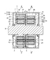
そして図8に詳細に示すように、ロータ7における超電導コイル13の一方の磁極面(13A)に対応するロータケース11の一方の面(具体的には外ケース11Aの一方の端面27)と、ステータ9における超電導コイル21の一方の磁極面(21A)に対応するステータケース19の一方の面(具体的には外ケース19Aの一方の端面29)とが、狭い空隙Gを隔てて相互に平行に対向する構成とされている。
As shown in detail in FIG. 8, one surface of the rotor case 11 (specifically, one
以上のような図5〜図8に示される超電導モータにおいて、例えばロータ(電機子)7の超電導コイル13に交流電流を流して、図5中の矢印Aで示すような交番磁場を生起させ、ステータ(界磁)9の超電導コイル21に直流電流を流して、図5の矢印Bで示すような一定磁場を生起させれば、一般のモータと同様に同期機として、ロータ7に回転力を与えることができる。
In the superconducting motor shown in FIGS. 5 to 8 as described above, for example, an alternating current is passed through the
なお前述のような図5〜図8の例では、ロータ7を電機子として交流電流を流し、ステータ9を界磁として直流電流を流しているが、逆にロータ7を界磁として直流電流を流し、ステータ9を電機子として交流電流を流しても良いことはもちろんである。但しその場合は、ロータ7の超電導コイル(界磁コイル)13の数は6個あるいはその倍数とし、ステータ9の超電導コイル(電機子コイル)21の数は8もしくはその倍数とするのが通常である。
In the examples of FIGS. 5 to 8 as described above, an alternating current is passed using the
なおまた、以上の例においては、ロータ7とステータ9との両者(電機子コイルおよび界磁コイル)に超電導コイルを用いているが、いずれか一方、例えばロータ7に常磁性コイルを用いて、ステータ9に超電導コイルを用いたり、逆にステータ9に常磁性コイルを用いて、ロータ7に超電導コイルを用いることもある。そしてこのようにロータ7とステータ9のうち、いずれか一方に常磁性コイルを用いる場合は、その側の真空断熱層を省いて、ケースを1重構造とするのが通常である。
In the above example, superconducting coils are used for both the
さらに、ロータ7とステータ9とのうち、電機子の側のコイル(電機子コイル)を超電導コイルで構成して、界磁を永久磁石で構成することもある。
Further, in the
良く知られているように、一般に超電導マグネットについては、超電導特性を発揮させるために液体窒素等の冷却媒体により超電導コイルを低温に冷却する必要があり、さらに外部からの熱侵入を防止して、超電導コイルの低温状態を維持するため、超電導コイルの外側を真空断熱層により取囲んでおく必要がある。そして図5〜図8の超電導モータでも、ロータ7およびステータ9の内ケース11B,19B内に液体窒素等の冷却媒体15,23を充填するとともに、ロータ7の外ケース11Aと内ケース11Bとの間に真空断熱層17を設け、かつステータ9の外ケース19Aと内ケース19Bとの間に真空断熱層25を設けている。したがってロータ7の超電導コイル13の端面(磁極面)13Aと、ステータ9の超電導コイル21の端面(磁極面)21Aとの間には、外ケース11A,19A間の空隙Gのみならず、真空断熱層17,25が介在することになる。
As is well known, in general, for a superconducting magnet, it is necessary to cool the superconducting coil to a low temperature with a cooling medium such as liquid nitrogen in order to exert superconducting properties, and further prevent heat penetration from the outside, In order to maintain the low temperature state of the superconducting coil, it is necessary to surround the outside of the superconducting coil with a vacuum heat insulating layer. 5 to 8, the
ところで超電導モータに限らず一般にモータにおいては、充分な回転出力を発生させるためには、相互に対向するロータ側の磁極面とステータ側の磁極面との間の間隔を可及的に小さくすることが望まれる。これを図5〜図8に示される超電導モータに即して言えば、ロータ7の超電導コイル13の磁極端面13Aとステータ9の超電導コイル21の磁極端面21Aとの間の距離L(図8参照)を可及的に小さくすることが望まれる。
By the way, not only a superconducting motor but generally a motor, in order to generate a sufficient rotational output, the distance between the rotor-side magnetic pole surface and the stator-side magnetic pole surface facing each other should be made as small as possible. Is desired. Speaking this to the superconducting motor shown in FIGS. 5 to 8, the distance L between the magnetic
しかるに、すでに述べたようにロータ7側の超電導コイル13の磁極面13Aとステータ9側の超電導コイル21の磁極面21Aとの間には、図8に詳細に示すように、真空断熱層17,25と、外ケース11A,19A、内ケース11B,19Bのそれぞれの壁とが介在しており、そのため磁極面13A,21A間の距離Lをある程度以上薄くすることは困難であった。
However, as already described, between the
すなわち、磁極面13A,21A間の距離Lは、ロータ側およびステータ側の外ケース11A,19A、内ケース11B,19Bのそれぞれの壁厚t1,t2,t3,t4と、真空断熱層17,25のそれぞれの厚みt5,t6と、空隙Gとの総和(t1+t2+t3+t4+t5+t6+G)で決定される。そのうち空隙Gはロータ回転時のぶれや誤差等を考慮すれば、ある程度以下に小さくすることは困難であり、通常は例えば5mm程度とされる。また真空断熱層17,25の厚みt5,t6も充分な断熱効果を確保する観点から、ある程度以上薄くすることは困難であり、通常は10mm程度は必要であるとされている。したがって前記距離Lを小さくするためには、外ケース11A、19A、内ケース11B,19Bの壁厚t1〜t4を薄くすることが考えられる。従来の超電導モータにおける外ケース11A,19A、内ケース11B,19Bの壁厚t1〜t4は、例えばそれぞれ30mm程度であって、これらの壁厚の合計の厚みは120mmにも達し、したがってこれらの壁厚を薄くすることによる距離Lの縮小効果は大きいと考えられる。しかしながら、外ケース11A,19A、内ケース11B,19Bのうちでも、特に外ケース11A,19Aは、その壁厚t1,t2を薄くした場合、次のような問題が発生する。
That is, the distance L between the
すなわち、ハウジング1内における外ケース11A,19Aの外側の空間は大気圧となっている一方、外ケース11A,19Aの内側、すなわち真空断熱層17,25の部分は真空となっているため、外ケース11A,19Aの壁には外側から内側へ向けて大気圧分の差圧が加わり、そのため外ケース11A,19Aの壁厚を小さくすれば、その剛性が低くなって、図8の鎖線で示すように外ケース11A,19Aの壁が前述の差圧により内側へ変形してしまうおそれがある。そして外ケース11A,19Aが極端に内側へ変形すれば、外ケース11A,19Aの内面が内ケース11B,19Bの外面に接触してしまい、その結果断熱効果が損なわれてしまう。したがって外ケース11A,19Aの壁厚t1,t2は、実際上はある程度以上薄くすることは困難であった。
That is, the space outside the
したがって以上から、図5〜図8に示すような従来の超電導モータにおいては、ロータ7の超電導コイル13の磁極面13Aとステータ9の超電導コイル21の磁極面21Aとの間の距離Lを小さくするにも限界があり、距離Lを小さくして超電導モータの回転出力を高めるにも限界があったのが実情である。
Therefore, from the above, in the conventional superconducting motor as shown in FIGS. 5 to 8, the distance L between the
この発明は以上の事情を背景としてなされたもので、超電導コイルを断熱するための真空断熱層の外側の壁、すなわち外ケースの壁を薄くしても大気圧との差圧による外ケースの壁の変形を招かないようにし、これによって外ケースの壁厚を薄くしてロータ、ステータの磁極面間の距離を従来よりも格段に小さくし得るようになし、もって超電導モータとしての回転出力を増大させ得るようにした超電導モータを提供することを目的とするものである。 The present invention has been made against the background described above. The outer wall of the vacuum heat insulating layer for insulating the superconducting coil, that is, the wall of the outer case due to the differential pressure from the atmospheric pressure even if the outer case wall is thinned. In this way, the wall thickness of the outer case can be reduced and the distance between the magnetic pole faces of the rotor and stator can be made much smaller than before, thereby increasing the rotational output as a superconducting motor. It is an object of the present invention to provide a superconducting motor that can be made to operate.
この発明の超電導モータは、基本的には、請求項1で規定したように、磁極面側が相互に平行に空隙を隔てて対向するロータとステータとのうち、少なくとも一方の電機子コイルもしくは界磁コイルとして、超電導コイルが使用されており、かつその超電導コイルは、外ケースと内ケースとの内外2重壁構造のケースにおける内ケースの内側に収納され、その内ケース内には、超電導コイルを冷却するための冷却媒体が充填されており、さらに外ケースと内ケースとの間の空間が真空断熱層とされた超電導モータにおいて、前記超電導コイルを収納したケースの外ケース内には、ステータとロータとが対向する方向に沿って伸長されかつ内ケースおよび超電導コイルの内周側を貫通する柱状体が配設されており、その柱状体の両端が外ケースの内面に接して、その柱状体により外ケースの内側への変形を防止するように構成したことを特徴とするものである。
The superconducting motor according to the present invention basically has at least one armature coil or field of the rotor and the stator facing each other with a gap between the magnetic pole surfaces parallel to each other as defined in
また請求項2の発明は、請求項1に記載の超電導モータにおいて、前記柱状体の両端が外ケースの内面に固定されていることを特徴とするものである。 According to a second aspect of the present invention, in the superconducting motor according to the first aspect, both ends of the columnar body are fixed to the inner surface of the outer case.
さらに請求項3の発明は、請求項1に記載の超電導モータにおいて、前記内ケースの内側における柱状体の外周面側の部分に、柱状体を取囲むように真空断熱層が形成されていることを特徴とするものである。
Furthermore, the invention of
さらにまた請求項4の発明は、請求項1に記載の超電導モータにおいて、前記柱状体が中空パイプによって構成されていることを特徴とするものである。
Further, the invention of claim 4 is the superconducting motor according to
またさらに請求項5の発明は、請求項4に記載の超電導モータにおいて、前記中空パイプの内側に磁性材が配設されていることを特徴とするものである。
Further, the invention of
この発明の超電導モータにおいては、超電導コイルに対する外部からの熱侵入防止のための真空断熱層の外側の壁、すなわちステータもしくはロータの外ケースの壁の内側への変形が、柱状体によって抑止されるため、大気圧との差圧により外ケースの内面が内ケースの外面に接触してしまうことを有効に防止でき、そのため外ケースの厚みを従来よりも格段に薄くすることができ、その結果ステータとロータとの磁極面間の距離を従来よりも格段に小さくして、モータとしての回転出力を増大させることができる。 In the superconducting motor of the present invention, deformation to the outside wall of the vacuum heat insulating layer for preventing heat from entering the superconducting coil, that is, the inside of the outer case wall of the stator or rotor is suppressed by the columnar body. Therefore, it is possible to effectively prevent the inner surface of the outer case from coming into contact with the outer surface of the inner case due to the pressure difference from the atmospheric pressure, and thus the thickness of the outer case can be significantly reduced as compared with the conventional case. The distance between the magnetic pole surfaces of the rotor and the rotor can be made much smaller than before, and the rotational output as a motor can be increased.
図1〜図3にこの発明の超電導モータの基本的な実施例を示す。なおこの図1〜図3の実施例は、図5〜図8に示す従来技術と同様に、ロータおよびステータの両者に超電導コイルを用いて、ロータを電機子、ステータを界磁とした例、すなわちロータの電機子コイルとステータの界磁コイルとをそれぞれ超電導コイルで構成した例として示すものである。また図1〜図3において、図5〜図8に示される従来技術の超電導モータと同一の構成要素については同一の符号を付し、その説明は省略する。 1 to 3 show a basic embodiment of the superconducting motor of the present invention. 1 to 3 is an example in which a superconducting coil is used for both the rotor and the stator, the rotor is an armature, and the stator is a field, as in the prior art shown in FIGS. In other words, the armature coil of the rotor and the field coil of the stator are shown as examples composed of superconducting coils. 1 to 3, the same components as those of the conventional superconducting motor shown in FIGS. 5 to 8 are denoted by the same reference numerals, and the description thereof is omitted.
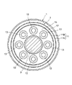
図1〜図3において、ロータ7の外ケース11A内には、各超電導コイル13の内周側を貫通しかつ内ケース11Bの壁を貫通するように、ロータ7とステータ9とが対向する方向(それぞれの磁極面が対向する方向)に沿って伸張するFRP等からなる柱状体29が、各超電導コイル13に対応して配設されている。そして各柱状体29の両端は、外ケース11Aの内面(平行な2面)に接している。ここで、柱状体29の両端は外ケース11Aの平行な2面の壁の内面側に形成した凹部に係合させるだけでも良いが、通常は接着剤等により固定しておくことが望ましい。さらに内ケース11Bの内側の部分における柱状体29の外周面側には、筒状に真空断熱層31が形成されており、この筒状真空断熱層31は、外ケース11Aと内ケース11Bとの間の真空断熱層17に連通している。なお各筒状真空断熱層31と内ケース11B内の液体窒素等の冷却媒体充填空間との間は、筒状の隔壁33によって隔てられている。
1 to 3, the
またステータ9の側も、同様に柱状体35を設けた構成とされている。すなわち、ステータ9の外ケース19A内には、各超電導コイル21の内周側を貫通しかつ内ケース19Bの壁を貫通するように、ロータ7とステータ9とが対向する方向(それぞれの磁極面が対向する方向)に沿って伸張する柱状体35が、各超電導コイル21に対応して配設されている。そして各柱状体35の両端は、外ケース19Aの内面(平行な2面)に接している。ここで、柱状体35の両端は外ケース19Aの平行な2面の壁の内面側に形成した凹部に係合させるだけでも良いが、通常は接着剤等により固定しておくことが望ましい。さらに内ケース19Bの内側の部分における柱状体35の外周面側には、筒状に真空断熱層37が形成されており、この筒状真空断熱層37は、外ケース19Aと内ケース19Bとの間の真空断熱層25に連通している。なお各筒状真空断熱層37と内ケース19B内の液体窒素等の冷却媒体充填空間との間は、筒状の隔壁39によって隔てられている。
Similarly, the
以上のような図1〜図3に示される超電導モータにおいて、ハウジング1内におけるロータ7の外ケース11Aおよびステータ9の外ケース19Aの外側の空間は、外部の大気とベアリング5の部分を介して連通しているから、その空間には大気圧が加わっている。一方、ロータ7およびステータ9の各外ケース11A,19Aの内側は真空断熱層17,25が位置しているから、その内側は真空となっている。したがって外ケース11A,19Aの壁には、大気圧分の差圧が外側から内側に向って加わることになる。しかるに、図1〜図3の超電導モータにおいては、ロータ7の8個の超電導コイル13のそれぞれに対応する位置に柱状体29が配設され、また同様にステータ9の側の6個の超電導コイル21のそれぞれに対応する位置に柱状体35が配設されており、これらの柱状体29,35が、その軸線方向(縦方向)の剛性により、ロータ7、ステータ9の外ケース11A,19Aの平行な2面の間での突っ張りの機能を果たし、前述の大気圧分の差圧により外ケース11A,19Aが内側に変形してしまうことを防止することができる。したがって外ケース11A,19Aは、その壁自身の厚みにより前述の大気圧分の差圧による変形を防止する必要がなくなるため、外ケース11A,19Aの壁厚を従来よりも格段に薄くし、例えば従来は30mm程度の厚みが必要だったのに対し、5mm程度まで薄くすることができる。したがって図5〜図8に示す従来技術の場合には磁極面13A,21Aの間の距離Lが145mm程度は必要であったのに対し、この発明の実施例では95mm程度で足りることになり、約35%も距離Lを短縮することが可能となる。
In the superconducting motor shown in FIGS. 1 to 3 as described above, the space outside the
なお図示の例では、内ケース11B,19B内における各柱状体29,35の外周側に筒状真空断熱層31,37が設けられているから、外部からの柱状体29,35を介しての熱侵入は防止することができる。
In the illustrated example, since the cylindrical vacuum
ここで、各柱状体29,35としては種々の材料を用いることができ、また中空体、中実体のいずれも使用することができるが、通常はFRP等からなる中空パイプを用いることが望ましい。また各柱状体29,35として非磁性材の中空パイプを用いる場合、その中空パイプの内側にケイ素鋼等の磁性材を配しても良く、その場合には中空パイプの内側の磁性材が各超電導コイル13,21に対応する鉄心(コア)の機能を果たすため、より強い磁界を生起させることができる。
Here, various materials can be used for each of the
なおここで、前述の例とは逆に、ロータ7を界磁として6個もしくはその倍数の超電導コイル(界磁コイル)13で構成し、ステータ9を電機子として8個もしくはその倍数の超電導コイル(電機子コイル)21で構成しても良い。
Here, contrary to the above-described example, the
さらに、図1〜図3に示す例では、ロータ7とステータ9との両者に超電導コイルを用いているが、場合によっては一方のみに超電導コイルを用い、他方には常磁性コイルを用いても良い。例えばステータ9を超電導コイルで構成し、ロータ7を常磁性コイルで構成した例を図4に示す。
Further, in the example shown in FIGS. 1 to 3, superconducting coils are used for both the
図4において、ステータ9の構成は図1〜図3に示した例と同様であるが、ロータ7のコイルとしては、常電導コイル41を用い、かつケース11を1重の構成とし、図1〜図3における真空断熱層17を省いたものとしている。この場合、ロータ7のケース11には大気圧分の差圧が加わらないため、ロータ7側には前述のような柱状体を設ける必要はない。
4, the configuration of the
逆にロータ7に超電導コイルを用い、ステータ9のコイルとして常磁性コイルを用いることもでき、その場合の例は特に図示しないが、ロータ7は、図1〜図3に示される例と同様に構成し、ステータ9は図4の例におけるロータ7に準じた構成とすれば良い。
Conversely, a superconducting coil can be used for the
さらに、図1〜図3の例では、ロータ7とステータ9のうち、一方のコイルは交流を流す電機子コイルとし、他方のコイルは直流を流す界磁コイルとしているが、界磁の側にはコイルに代えて永久磁石を用いても良いことはもちろんである。
Further, in the example of FIGS. 1 to 3, one of the
7 ロータ
9 ステータ
11 ロータケース
11A 外ケース
11B 内ケース
13 超電導コイル
15 冷却媒体
17 真空断熱層
19 ステータケース
19A 外ケース
19B 内ケース
21 超電導コイル
23 冷却媒体
25 真空断熱層
29 柱状体
31 真空断熱層
35 柱状体
37 真空断熱層
G 空隙
7
Claims (5)
前記超電導コイルを収納したケースの外ケース内には、ステータとロータとが対向する方向に沿って伸長されかつ内ケースおよび超電導コイルの内周側を貫通する柱状体が配設されており、その柱状体の両端が外ケースの内面に接して、その柱状体により外ケースの内側への変形を防止するように構成したことを特徴とする、超電導モータ。 A superconducting coil is used as at least one armature coil or field coil of the rotor and stator whose pole face sides are parallel to each other with a gap therebetween, and the superconducting coil is connected to the outer case and the inner case. It is housed inside the inner case in the case of the inner and outer double wall structure with the case, the inner case is filled with a cooling medium for cooling the superconducting coil, and further between the outer case and the inner case In a superconducting motor in which the space is a vacuum heat insulating layer,
In the outer case of the case containing the superconducting coil, a columnar body that extends along the direction in which the stator and the rotor face each other and penetrates the inner case and the inner peripheral side of the superconducting coil is disposed. A superconducting motor characterized in that both ends of a columnar body are in contact with the inner surface of the outer case, and the columnar body prevents deformation to the inside of the outer case.
Priority Applications (1)
| Application Number | Priority Date | Filing Date | Title |
|---|---|---|---|
| JP2004378661A JP4616640B2 (en) | 2004-12-28 | 2004-12-28 | Superconducting motor |
Applications Claiming Priority (1)
| Application Number | Priority Date | Filing Date | Title |
|---|---|---|---|
| JP2004378661A JP4616640B2 (en) | 2004-12-28 | 2004-12-28 | Superconducting motor |
Publications (2)
| Publication Number | Publication Date |
|---|---|
| JP2006187136A JP2006187136A (en) | 2006-07-13 |
| JP4616640B2 true JP4616640B2 (en) | 2011-01-19 |
Family
ID=36739810
Family Applications (1)
| Application Number | Title | Priority Date | Filing Date |
|---|---|---|---|
| JP2004378661A Expired - Lifetime JP4616640B2 (en) | 2004-12-28 | 2004-12-28 | Superconducting motor |
Country Status (1)
| Country | Link |
|---|---|
| JP (1) | JP4616640B2 (en) |
Families Citing this family (2)
| Publication number | Priority date | Publication date | Assignee | Title |
|---|---|---|---|---|
| WO2020083670A1 (en) * | 2018-10-22 | 2020-04-30 | Rolls-Royce Deutschland Ltd & Co Kg | Cryogenic cooling in electrical machines |
| CN112217376B (en) * | 2020-10-10 | 2025-03-04 | 苏州英磁新能源科技有限公司 | A rotor superconducting structure |
Family Cites Families (2)
| Publication number | Priority date | Publication date | Assignee | Title |
|---|---|---|---|---|
| JPS5858860A (en) * | 1981-09-30 | 1983-04-07 | Hitachi Ltd | Multiple cylindrical rotor |
| US6605886B2 (en) * | 2001-07-31 | 2003-08-12 | General Electric Company | High temperature superconductor synchronous rotor coil support insulator |
-
2004
- 2004-12-28 JP JP2004378661A patent/JP4616640B2/en not_active Expired - Lifetime
Also Published As
| Publication number | Publication date |
|---|---|
| JP2006187136A (en) | 2006-07-13 |
Similar Documents
| Publication | Publication Date | Title |
|---|---|---|
| JP5605388B2 (en) | Synchronous motor | |
| CN103872868B (en) | Multiple level formula electric rotating machine | |
| JP5074350B2 (en) | Magnetic bearing | |
| US9774223B2 (en) | Permanent magnet synchronous machine | |
| JP2009201269A (en) | Embedded magnet motor and manufacturing method therefor | |
| JP6573032B2 (en) | Rotor | |
| JP2014075892A (en) | Rotor of rotary electric machine | |
| US20190140500A1 (en) | Permanent magnet motor | |
| JP2014103741A (en) | Magnet embedded type rotor | |
| JP4687687B2 (en) | Axial gap type rotating electric machine and field element | |
| JP2009219312A (en) | Rotating electric machine and spindle unit using same | |
| JPH09308195A (en) | Rotor of rotating electric machine | |
| WO2014156678A1 (en) | Electric motor | |
| US20230412022A1 (en) | Field magneton | |
| JP4616640B2 (en) | Superconducting motor | |
| JP2009106001A (en) | Rotating electric machine | |
| JP2015089149A (en) | Multi-gap type rotary electric machine | |
| WO2017064938A1 (en) | Dynamo-electric machine | |
| JP5481806B2 (en) | Permanent magnet synchronous motor | |
| JP2008220128A (en) | Axial gap type rotating electric machine and compressor | |
| JP2008172918A (en) | Axial gap type motor and compressor | |
| JP2006174550A (en) | Stator structure of disk type rotating electrical machine | |
| JP2013255371A (en) | Permanent magnet synchronous machine | |
| JP5332335B2 (en) | Rotor | |
| JPWO2018198217A1 (en) | Permanent magnet type motor |
Legal Events
| Date | Code | Title | Description |
|---|---|---|---|
| RD01 | Notification of change of attorney |
Free format text: JAPANESE INTERMEDIATE CODE: A7426 Effective date: 20060512 |
|
| A521 | Request for written amendment filed |
Free format text: JAPANESE INTERMEDIATE CODE: A821 Effective date: 20060512 |
|
| A711 | Notification of change in applicant |
Free format text: JAPANESE INTERMEDIATE CODE: A711 Effective date: 20060512 |
|
| A621 | Written request for application examination |
Free format text: JAPANESE INTERMEDIATE CODE: A621 Effective date: 20071219 |
|
| A521 | Request for written amendment filed |
Free format text: JAPANESE INTERMEDIATE CODE: A523 Effective date: 20080218 |
|
| RD03 | Notification of appointment of power of attorney |
Free format text: JAPANESE INTERMEDIATE CODE: A7423 Effective date: 20090730 |
|
| A521 | Request for written amendment filed |
Free format text: JAPANESE INTERMEDIATE CODE: A821 Effective date: 20090730 |
|
| TRDD | Decision of grant or rejection written | ||
| A01 | Written decision to grant a patent or to grant a registration (utility model) |
Free format text: JAPANESE INTERMEDIATE CODE: A01 Effective date: 20100929 |
|
| A01 | Written decision to grant a patent or to grant a registration (utility model) |
Free format text: JAPANESE INTERMEDIATE CODE: A01 |
|
| A61 | First payment of annual fees (during grant procedure) |
Free format text: JAPANESE INTERMEDIATE CODE: A61 Effective date: 20101022 |
|
| R150 | Certificate of patent or registration of utility model |
Ref document number: 4616640 Country of ref document: JP Free format text: JAPANESE INTERMEDIATE CODE: R150 Free format text: JAPANESE INTERMEDIATE CODE: R150 |
|
| FPAY | Renewal fee payment (event date is renewal date of database) |
Free format text: PAYMENT UNTIL: 20131029 Year of fee payment: 3 |
|
| FPAY | Renewal fee payment (event date is renewal date of database) |
Free format text: PAYMENT UNTIL: 20131029 Year of fee payment: 3 |
|
| S111 | Request for change of ownership or part of ownership |
Free format text: JAPANESE INTERMEDIATE CODE: R313115 |
|
| FPAY | Renewal fee payment (event date is renewal date of database) |
Free format text: PAYMENT UNTIL: 20131029 Year of fee payment: 3 |
|
| R350 | Written notification of registration of transfer |
Free format text: JAPANESE INTERMEDIATE CODE: R350 |
|
| R250 | Receipt of annual fees |
Free format text: JAPANESE INTERMEDIATE CODE: R250 |
|
| R250 | Receipt of annual fees |
Free format text: JAPANESE INTERMEDIATE CODE: R250 |
|
| R250 | Receipt of annual fees |
Free format text: JAPANESE INTERMEDIATE CODE: R250 |
|
| S111 | Request for change of ownership or part of ownership |
Free format text: JAPANESE INTERMEDIATE CODE: R313117 |
|
| R250 | Receipt of annual fees |
Free format text: JAPANESE INTERMEDIATE CODE: R250 |
|
| R350 | Written notification of registration of transfer |
Free format text: JAPANESE INTERMEDIATE CODE: R350 |
|
| R250 | Receipt of annual fees |
Free format text: JAPANESE INTERMEDIATE CODE: R250 |
|
| EXPY | Cancellation because of completion of term |