JP4615422B2 - Heat transfer tubes, heat exchangers for hot water supply and heat pump water heaters - Google Patents
Heat transfer tubes, heat exchangers for hot water supply and heat pump water heaters Download PDFInfo
- Publication number
- JP4615422B2 JP4615422B2 JP2005328638A JP2005328638A JP4615422B2 JP 4615422 B2 JP4615422 B2 JP 4615422B2 JP 2005328638 A JP2005328638 A JP 2005328638A JP 2005328638 A JP2005328638 A JP 2005328638A JP 4615422 B2 JP4615422 B2 JP 4615422B2
- Authority
- JP
- Japan
- Prior art keywords
- tube
- heat transfer
- refrigerant
- heat
- heat exchanger
- Prior art date
- Legal status (The legal status is an assumption and is not a legal conclusion. Google has not performed a legal analysis and makes no representation as to the accuracy of the status listed.)
- Active
Links
- 238000012546 transfer Methods 0.000 title claims description 90
- XLYOFNOQVPJJNP-UHFFFAOYSA-N water Substances O XLYOFNOQVPJJNP-UHFFFAOYSA-N 0.000 title claims description 60
- 239000003507 refrigerant Substances 0.000 claims description 58
- 239000008399 tap water Substances 0.000 claims description 10
- 235000020679 tap water Nutrition 0.000 claims description 10
- 239000002826 coolant Substances 0.000 claims 2
- CURLTUGMZLYLDI-UHFFFAOYSA-N Carbon dioxide Chemical compound O=C=O CURLTUGMZLYLDI-UHFFFAOYSA-N 0.000 description 16
- 230000000052 comparative effect Effects 0.000 description 16
- 238000011156 evaluation Methods 0.000 description 11
- 239000001569 carbon dioxide Substances 0.000 description 8
- 229910002092 carbon dioxide Inorganic materials 0.000 description 8
- 238000000034 method Methods 0.000 description 5
- VYPSYNLAJGMNEJ-UHFFFAOYSA-N Silicium dioxide Chemical compound O=[Si]=O VYPSYNLAJGMNEJ-UHFFFAOYSA-N 0.000 description 4
- 238000009825 accumulation Methods 0.000 description 4
- 230000008021 deposition Effects 0.000 description 4
- 238000010586 diagram Methods 0.000 description 4
- 239000000463 material Substances 0.000 description 4
- 230000006866 deterioration Effects 0.000 description 3
- 230000007774 longterm Effects 0.000 description 3
- 238000012360 testing method Methods 0.000 description 3
- OYPRJOBELJOOCE-UHFFFAOYSA-N Calcium Chemical compound [Ca] OYPRJOBELJOOCE-UHFFFAOYSA-N 0.000 description 2
- RYGMFSIKBFXOCR-UHFFFAOYSA-N Copper Chemical group [Cu] RYGMFSIKBFXOCR-UHFFFAOYSA-N 0.000 description 2
- 229910052791 calcium Inorganic materials 0.000 description 2
- 239000011575 calcium Substances 0.000 description 2
- KYKAJFCTULSVSH-UHFFFAOYSA-N chloro(fluoro)methane Chemical compound F[C]Cl KYKAJFCTULSVSH-UHFFFAOYSA-N 0.000 description 2
- 229910052802 copper Inorganic materials 0.000 description 2
- 239000010949 copper Substances 0.000 description 2
- 238000005260 corrosion Methods 0.000 description 2
- 230000007797 corrosion Effects 0.000 description 2
- 239000000377 silicon dioxide Substances 0.000 description 2
- UXVMQQNJUSDDNG-UHFFFAOYSA-L Calcium chloride Chemical compound [Cl-].[Cl-].[Ca+2] UXVMQQNJUSDDNG-UHFFFAOYSA-L 0.000 description 1
- 229910000881 Cu alloy Inorganic materials 0.000 description 1
- 239000004115 Sodium Silicate Substances 0.000 description 1
- 230000001133 acceleration Effects 0.000 description 1
- 239000001110 calcium chloride Substances 0.000 description 1
- 229910001628 calcium chloride Inorganic materials 0.000 description 1
- 230000006835 compression Effects 0.000 description 1
- 238000007906 compression Methods 0.000 description 1
- 238000001816 cooling Methods 0.000 description 1
- 238000001514 detection method Methods 0.000 description 1
- 230000000694 effects Effects 0.000 description 1
- 230000007613 environmental effect Effects 0.000 description 1
- 239000012530 fluid Substances 0.000 description 1
- 239000000446 fuel Substances 0.000 description 1
- 238000010438 heat treatment Methods 0.000 description 1
- BHEPBYXIRTUNPN-UHFFFAOYSA-N hydridophosphorus(.) (triplet) Chemical compound [PH] BHEPBYXIRTUNPN-UHFFFAOYSA-N 0.000 description 1
- 229910052751 metal Inorganic materials 0.000 description 1
- 239000002184 metal Substances 0.000 description 1
- VUZPPFZMUPKLLV-UHFFFAOYSA-N methane;hydrate Chemical compound C.O VUZPPFZMUPKLLV-UHFFFAOYSA-N 0.000 description 1
- 238000012986 modification Methods 0.000 description 1
- 230000004048 modification Effects 0.000 description 1
- 230000005855 radiation Effects 0.000 description 1
- 229920006395 saturated elastomer Polymers 0.000 description 1
- 235000019795 sodium metasilicate Nutrition 0.000 description 1
- NTHWMYGWWRZVTN-UHFFFAOYSA-N sodium silicate Chemical compound [Na+].[Na+].[O-][Si]([O-])=O NTHWMYGWWRZVTN-UHFFFAOYSA-N 0.000 description 1
- 229910052911 sodium silicate Inorganic materials 0.000 description 1
- 239000010935 stainless steel Substances 0.000 description 1
- 229910001220 stainless steel Inorganic materials 0.000 description 1
Images


Landscapes
- Details Of Fluid Heaters (AREA)
- Heat-Pump Type And Storage Water Heaters (AREA)
Description
本発明は、熱交換器に使用される伝熱管、特に給湯水を管内に流通するヒートポンプ給湯器用熱交換器に使用される伝熱管に関するものである。 The present invention relates to a heat transfer tube used in a heat exchanger, and more particularly to a heat transfer tube used in a heat exchanger for a heat pump water heater that distributes hot water in the tube.
地球環境保全の観点から二酸化炭素排出量を削減するために各種の伝熱機器の開発が行われている。温水を製造するための給湯器は都市ガスや油系燃料による加熱で製造することが多かったが、電力駆動による圧縮機で冷媒を循環して熱サイクルを形成することによって温水を製造するヒートポンプ給湯器の高性能化が進んでいる。ヒートポンプ給湯器では冷媒にフロンではなく二酸化炭素を使用することが多くなっており、脱フロンにも寄与している。 Various heat transfer devices have been developed to reduce carbon dioxide emissions from the viewpoint of global environmental conservation. Hot water heaters for producing hot water were often manufactured by heating with city gas or oil-based fuel, but heat pump water heaters for producing hot water by forming a heat cycle by circulating refrigerant in a compressor driven by electric power The performance of the vessel is increasing. In heat pump water heaters, carbon dioxide is often used instead of chlorofluorocarbon as a refrigerant, which contributes to chlorofluorocarbon removal.
このようなヒートポンプ給湯器は、一般的に次に記載するようなシステムで形成されている。すなわち、圧縮機で高温高圧にされた冷媒は、ガスクーラーと呼ばれる熱交換器に送られ、水道水と熱交換することにより給湯に用いる温水を製造する。ガスクーラーで低温化された冷媒は、膨張弁で低圧化されて、室外に設置される蒸発器で外気により気化されて再び圧縮機で高温高圧化される。 Such a heat pump water heater is generally formed by a system as described below. That is, the high-temperature and high-pressure refrigerant in the compressor is sent to a heat exchanger called a gas cooler, and hot water used for hot water supply is produced by exchanging heat with tap water. The refrigerant whose temperature has been reduced by the gas cooler is reduced in pressure by the expansion valve, is vaporized by the outside air in the evaporator installed outside the room, and is again increased in temperature and pressure by the compressor.
流体の熱伝達率を向上させるための管の内壁面のフィンを付加してガスクーラーの性能を向上した例がある(例えば特許文献1)。
しかしながら、特許文献1記載の熱交換器では、水道水が高温化されるので、その水道水内に含まれるカルシウムやシリカが析出(一般的にスケールと呼ぶ)して管内壁面に付着しやすくなり、管につまりが生じやすくなるという問題が生じる。特に、管内面にフィンを付加すると、隣り合うフィンの間にその析出物が堆積して経時的にフィン付加による熱伝達率向上の効果が劣化する。
However, in the heat exchanger described in
このような問題に鑑み、本発明はなされたもので、長期間の使用過程においてスケール堆積が生じにくいことにより、良好な熱交換特性を維持できる伝熱管を提供するものである。 In view of such a problem, the present invention has been made, and provides a heat transfer tube capable of maintaining good heat exchange characteristics because scale deposition hardly occurs during a long-term use process.
本発明に係る熱交換器の第1の態様は、管の内面からの高さhが前記管の内径dに対して0.01d〜0.13dであり、前記管の軸方向に形成された0.5〜1.8mmの距離aを有する溝によってそれぞれ挟まれた、複数の螺旋状のフィンを備え、管の内面に形成されるフィンと、前記フィンと隣り合うフィンとの間に形成される溝との接続部Frの曲率半径αが0.03〜0.5mmである、水道水が流れる伝熱管と、冷媒用の管とを備えた熱交換器であって、前記冷媒用の管と前記伝熱管とが密着接合されており、前記冷媒用の管が前記伝熱管で挟まれた構造を有することを特徴とする、熱交換器である。 A first aspect of the heat exchanger according to the present invention is 0.0 1 d~0.1 3 d is a height h from the inner face of the tube against the inner diameter d of the tube, the axial direction of the tube A plurality of spiral fins sandwiched between grooves a having a distance a of 0.5 to 1.8 mm formed on the fin, the fin formed on the inner surface of the tube, and the fin adjacent to the fin, A heat exchanger provided with a heat transfer pipe through which tap water flows , and a pipe for refrigerant, the curvature radius α of the connecting part Fr with the groove formed between the pipes is 0.03 to 0.5 mm , The heat exchanger is characterized in that the refrigerant tube and the heat transfer tube are in close contact with each other, and the refrigerant tube is sandwiched between the heat transfer tubes.
本発明に係る熱交換器の第2の態様は、管の内面からの高さhが前記管の内径dに対して0.01d〜0.13dであり、前記管の軸方向に形成された0.5〜1.8mmの距離aを有する溝によってそれぞれ挟まれた、複数の螺旋状のフィンを備え、管の内面に形成されるフィンと、前記フィンと隣り合うフィンとの間に形成される溝との接続部Frが、少なくとももう一段の面を形成する、水道水が流れる伝熱管と、冷媒用の管とを備えた熱交換器であって、前記冷媒用の管と前記伝熱管とが密着接合されており、前記冷媒用の管が前記伝熱管で挟まれた構造を有することを特徴とする、熱交換器である。 In the second aspect of the heat exchanger according to the present invention, the height h from the inner surface of the tube is 0.01d to 0.13d with respect to the inner diameter d of the tube, and is formed in the axial direction of the tube. A plurality of spiral fins sandwiched between grooves a having a distance a of 0.5 to 1.8 mm, each of which is formed between a fin formed on the inner surface of the tube and a fin adjacent to the fin. A heat exchanger comprising a heat transfer pipe through which tap water flows and a refrigerant pipe, at which the connecting portion Fr to the groove forms at least another surface, the refrigerant pipe and the heat transfer pipe Is a heat exchanger, wherein the refrigerant pipe is sandwiched between the heat transfer pipes.
本発明に係る熱交換器の第3の態様は、前記冷媒用の管が2本又は3本であり、前記伝熱管、前記冷媒用の管、及びこれらの接合部で囲まれた範囲に隙間部が形成され、該隙間部により冷媒又は水の漏洩を検知出来るようにした熱交換器である。 In a third aspect of the heat exchanger according to the present invention, the refrigerant pipe has two or three pipes, and a gap is provided in a range surrounded by the heat transfer pipe, the refrigerant pipe, and a joint portion thereof. This is a heat exchanger in which a portion is formed and leakage of refrigerant or water can be detected by the gap.
本発明に係る熱交換器の第4の態様は、前記冷媒用の管と、前記伝熱管とが並列に渦巻くように形成されていることにより、前記冷媒用の管が前記伝熱管で挟まれた構造を有する熱交換器である。 According to a fourth aspect of the heat exchanger of the present invention, the refrigerant tube and the heat transfer tube are formed so as to spiral in parallel, whereby the refrigerant tube is sandwiched between the heat transfer tubes. It is a heat exchanger having a structure.
本発明に係るヒートポンプ給湯器の第1の態様は、上述した熱交換器と、当該熱交換器から流出する冷媒を減圧する膨張弁と、膨張弁で減圧された前記冷媒を蒸発させる蒸発器と、前記冷媒を圧縮する圧縮機とを備える一次冷媒回路と、前記熱交換器に水を導出する循環ポンプと、前記熱交換器で加熱された水を貯蔵する給湯タンクとを備えるヒートポンプ給湯器である。 A first aspect of the heat pump water heater according to the present invention includes the above-described heat exchanger, an expansion valve that depressurizes the refrigerant flowing out of the heat exchanger, and an evaporator that evaporates the refrigerant depressurized by the expansion valve. A heat pump water heater comprising: a primary refrigerant circuit comprising a compressor for compressing the refrigerant; a circulation pump for leading water to the heat exchanger; and a hot water tank for storing water heated by the heat exchanger. is there.
本発明による熱交換器によれば、ヒートポンプ等に用いられる伝熱管について、長期間の使用過程においてスケール堆積が生じにくいため、良好な熱交換特性を維持できる伝熱管を提供することができる。 The heat exchanger according to the present invention can provide a heat transfer tube that can maintain good heat exchange characteristics because scale deposition is unlikely to occur during a long-term use process for a heat transfer tube used in a heat pump or the like.
以下、本発明の実施形態について、図1から図9を参照して、詳細に説明する。 Hereinafter, embodiments of the present invention will be described in detail with reference to FIGS. 1 to 9.
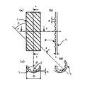
図1は、本発明に係る伝熱管を示す一実施例の模式図である。図1(a)は、伝熱管の平面図である。図1(b)は、伝熱管の矢視xの縦断面図である。図1(c)は、伝熱管の矢視yの横断面図である。図1(d)は伝熱管の矢視zの斜め断面図である。 FIG. 1 is a schematic view of an embodiment showing a heat transfer tube according to the present invention. Fig.1 (a) is a top view of a heat exchanger tube. FIG.1 (b) is a longitudinal cross-sectional view of arrow x of a heat exchanger tube. FIG.1 (c) is a cross-sectional view of the heat exchanger tube of the arrow y. FIG.1 (d) is a diagonal sectional view of the heat exchanger tube of the arrow z.
本発明の伝熱管において、図1(c)に示すフィン2の高さ(または溝の深さ)hを管内径dに対して0.005d〜0.19dとする。高さhが0.005dより小さいと螺旋状のフィンまたは溝による伝熱性能が劣るためである。逆に、高さhが0.19dよりも大きくなっても伝熱性能の向上は飽和するばかりでなく、管内のフィンとフィンとの間に形成される面溝部へのスケールの堆積が生じやすくなってしまうためである。好ましくは0.01d〜0.13dである。
In the heat transfer tube of the present invention, the height (or groove depth) h of the
本発明の伝熱管において、図1(b)に示す管の軸方向に隣り合う溝の距離aを0.4mm以上とする。距離aが0.4mm未満であると管内の面溝部へのスケールの堆積が生じやすくなってしまうためである。好ましくは距離aが0.5〜1.8mmである。 In the heat transfer tube of the present invention, the distance a between adjacent grooves in the axial direction of the tube shown in FIG. This is because if the distance a is less than 0.4 mm, scale is likely to be deposited on the surface groove in the pipe. The distance a is preferably 0.5 to 1.8 mm.
さらに、本発明の伝熱管のフィンの特性について図面を参照しながら詳細に説明する。なお、図1に示される伝熱管の各部と同様の構成には同一符号を付し、その説明を省略する。 Further, the characteristics of the fins of the heat transfer tube of the present invention will be described in detail with reference to the drawings. In addition, the same code | symbol is attached | subjected to the structure similar to each part of the heat exchanger tube shown by FIG. 1, and the description is abbreviate | omitted.
図2は、フィンの形状の1つの態様を模式的に示す断面図である。なお、ここでは、図2に示すように、管の内面に形成されるフィン2と接続部Frが曲面である場合を曲面接合と分類する。曲面接合で管の内面に形成されるフィン2と、その隣り合うフィン2によって、その間に形成される溝との接続部Frの曲率半径αを0.03〜0.5mmとする。曲率半径αが0.03mm未満であると、曲面接合の接続部Frにスケールの堆積が生じやすくなってしまう。逆に、曲率半径αが0.5mmを越えると不必要に材料を必要とし、単位長さ管重量の増加という問題が生じる。好ましくは、曲率半径αが0.03〜0.4mmである。
FIG. 2 is a cross-sectional view schematically showing one aspect of the shape of the fin. Here, as shown in FIG. 2, the case where the
図3は、フィンの形状の他の態様を模式的に示す断面図である。また、ここでは、本発明の伝熱管において曲面接合の代替として、図3に示すように、管の内面のフィン2と管の接続部Frにおいてもう一段の面(テーパー)が形成されているものを面取接合と分類する。すなわち、フィン2と管の内面とは多角形の一部をなすよう形成される。この面取接合によりフィン2と溝部との境にスケールの堆積が生じにくくなる。なお、図3に示すbは、面取接合の面の高さを示し、cは、面取接合の面の幅を示す。
FIG. 3 is a cross-sectional view schematically showing another aspect of the shape of the fin. Further, here, as an alternative to curved surface joining in the heat transfer tube of the present invention, as shown in FIG. 3, another surface (taper) is formed at the
本発明の伝熱管の材質は、熱伝導性を有するものであれば良いが、好ましくは熱伝導性に優れる金属が良い。より好ましくは銅または銅合金である。 The material of the heat transfer tube of the present invention is not particularly limited as long as it has thermal conductivity, but a metal having excellent thermal conductivity is preferable. More preferably, it is copper or a copper alloy.
また、本発明の伝熱管は熱交換器に用いられ、特に、二酸化炭素を冷媒とし、水道水と熱交換するヒートポンプ給湯器に用いられる。 The heat transfer tube of the present invention is used in a heat exchanger, and in particular, in a heat pump water heater that uses carbon dioxide as a refrigerant and exchanges heat with tap water.
(実施例1)
以下に、実施例を用いて本発明に係る熱交換器を詳細に説明する。
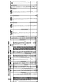
図4は、伝熱管の特性とその特性に基づく評価結果を示す表である。伝熱管の材質はリン脱酸銅を使用し、外径Dを9.52mm、内径dを7.92mm、管の長さを2.5m、管の肉厚tを0.8mmとした。その状態で、溝数、フィンの高さh、溝の距離a、接続部Frの曲率α、ねじれ角θを種々の条件で変化させ、伝熱管の評価を行った。
Example 1
Below, the heat exchanger concerning the present invention is explained in detail using an example.
FIG. 4 is a table showing the characteristics of the heat transfer tubes and the evaluation results based on the characteristics. Phosphorous deoxidized copper was used as the material for the heat transfer tube, the outer diameter D was 9.52 mm, the inner diameter d was 7.92 mm, the tube length was 2.5 m, and the tube thickness t was 0.8 mm. In this state, the number of grooves, fin height h, groove distance a, curvature α of connecting portion Fr, and torsion angle θ were changed under various conditions, and the heat transfer tubes were evaluated.
また、図5は、本発明に係る伝熱管の伝熱性能の評価方法を示す模式図である。図5に示すように、2重管式熱交換器により伝熱管1の伝熱性能を評価した。2重管式伝熱管の内管には、本発明例および比較例の伝熱管1を使用し、水温30度の低温水を流量2リットル/分で、図5に示す矢印3の方向に流した。外管4にはステンレス製の外径16mm、肉厚1mmの管を使用し、水温60度の高温水を流量3リットル/分で、図5に示す矢印5の方向に流した。
FIG. 5 is a schematic diagram showing a method for evaluating the heat transfer performance of the heat transfer tube according to the present invention. As shown in FIG. 5, the heat transfer performance of the
まず、伝熱性能の評価を調べるために、図4に示す実験条件の下で水の交換熱量Q1の測定を行った。なお、スケール直前の交換熱量Q1は、本発明例および比較例の伝熱管1と同じ外径を有し、管内面にフィンまたは溝が無い平滑管の交換熱量Q1を100とし(比較例7)、比較例7との比で本発明例1〜19及び比較例1〜6の交換熱量Q1を示した。
First, in order to examine the evaluation of the heat transfer performance, the exchange heat quantity Q1 of water was measured under the experimental conditions shown in FIG. The exchange heat quantity Q1 immediately before the scale has the same outer diameter as that of the
次に、伝熱管1の内面へのスケール付着による伝熱性能の影響について検討するため、以下に示すスケール付着加速試験を行なった。
Next, in order to examine the influence of the heat transfer performance due to the scale adhesion to the inner surface of the
本発明例および比較例の伝熱管1の内部に、カルシウム硬度が200mg/リットル、およびイオン状シリカが100mg/リットルになるように塩化カルシウムおよびメタケイ酸ナトリウムを添加して80℃に加熱した水道水を、流量2リットル/分で270日間通水した。なお、試験水は15日ごとに新しい液に交替した。
Tap water heated to 80 ° C. by adding calcium chloride and sodium metasilicate so that the calcium hardness is 200 mg / liter and the ionic silica is 100 mg / liter inside the
さらに前記実施例1と同じ方法で、通水開始より90日、180日、270日で、本発明例および比較例の伝熱管1の交換熱量を測定し、スケール付着前後による交換熱量の劣化を評価した。通水開始より90日、180日、270日のそれぞれの交換熱量をQ2、Q3、Q4とした。また、試験終了後(270日後)に、伝熱管1を切断して管内面のスケールの堆積状態を目視で確認した。ほとんど堆積していないものを○、やや堆積が見られるものを△、堆積が著しいものを×とした。伝熱管1の形状と評価結果を図4に示す。
Further, in the same manner as in Example 1, the exchange heat amount of the
図4から明らかなように、本願発明の伝熱管1はスケール堆積がしにくく、それにより交換熱量の劣化がほとんど無いため、良好な熱交換特性を維持している。それに対し、比較例1はh/dが0.005よりも小さいので伝熱性能が本発明例より劣った。また、比較例2は管の内面のフィン2と管の接続部Frにテーパーや曲面が形成されない接合(直接接合)なのでスケールが付着してしまい伝熱性能の低下が大きかった。比較例3と4はh/dが0.19よりも大きいのでスケールが付着してしまい伝熱性能の低下が大きかった。比較例5および6は溝の距離aが0.4mmよりも小さいため、スケールが付着してしまい伝熱性能の低下が大きかった。比較例7は平滑管なので交換熱量が本発明例より劣った。
As can be seen from FIG. 4, the
(実施例2)
次に、実施例1と同様、図5に示す評価方法を用いて、外径Dが12.7mm、内径dが11.1mm、肉厚tが0.8mmである伝熱管1を評価した。その他の条件は実施例1と同様である。伝熱管の形状と評価結果を図6に示す。
(Example 2)
Next, as in Example 1, the
図6は、第2実施例の伝熱管の特性とその特性に基づく評価結果を示す表である。図6から明らかなように、本願発明の伝熱管1はスケール堆積がしにくく、それにより交換熱量の劣化がほとんど無いため、良好な熱交換特性を維持している。それに対し、比較例8はh/dが0.005より小さいので本発明よりも伝熱性能が悪かった。比較例9はh/dが0.19より大きいので、スケールが付着してしまい伝熱性能が低下してしまった。比較例10は平滑管なので交換熱量が本発明例より低い。
FIG. 6 is a table showing the characteristics of the heat transfer tube of the second embodiment and the evaluation results based on the characteristics. As is apparent from FIG. 6, the
(実施例3)
さらに、実施例1で取り上げた、外径Dが9.52mm、肉厚tが0.8mmの本発明例15の伝熱管と、平滑管である図4に示す比較例7について、入口の水温10℃、水流量6〜9リットル/分(流速約2〜3m/sec)の範囲で、図5に示す評価方法を用いて交換熱量を測定した。その結果を図7に示す。
(Example 3)
Furthermore, the water temperature at the inlet of the heat transfer tube of the present invention example 15 having an outer diameter D of 9.52 mm and a wall thickness t of 0.8 mm and the comparative example 7 shown in FIG. The amount of exchange heat was measured using the evaluation method shown in FIG. 5 at a temperature of 10 ° C. and a water flow rate of 6 to 9 liters / minute (flow rate of about 2 to 3 m / sec). The result is shown in FIG.
図7は、第3実施例の伝熱管の特性とその特性に基づく評価結果を示す表である。図7より分かるように、本発明なる伝熱管は水流量が多くなっても高い伝熱性能を得ることができる。このことは、本発明なる伝熱管が、給湯器だけに限らず、各種の高温媒体を冷却するための伝熱管として使用しても効果を得るものであることを示している。 FIG. 7 is a table showing the characteristics of the heat transfer tube of the third embodiment and the evaluation results based on the characteristics. As can be seen from FIG. 7, the heat transfer tube of the present invention can obtain high heat transfer performance even when the water flow rate is increased. This indicates that the heat transfer tube according to the present invention is not limited to only a water heater, but can be used effectively as a heat transfer tube for cooling various high-temperature media.
(実施例4)
図8は、本発明の伝熱管を備える熱交換器の一例を示す平面図である。図8に示すように、本発明に係る熱交換器13は、二酸化炭素などの冷媒が流れる管6を、水が流れる伝熱管1で挟む構造をしており、かつ、両者を接合材により接合して密着することによって、管6から放熱される熱が大気へ放出されることなしに、伝熱管1に伝わり、効率良く伝熱管1と熱交換を行うものである。
Example 4
FIG. 8 is a plan view showing an example of a heat exchanger provided with the heat transfer tube of the present invention. As shown in FIG. 8, the
冷媒は図8に示す矢印9に沿って管2に流入する一方で、水は図8に示す矢印10に沿って伝熱管1を流出する。したがって、管の内部を流れる冷媒と水は、対向流れとなるように構成されている。
While the refrigerant flows into the
さらに、本発明の熱交換器について、図8に示すa−a断面図を用いて詳細に説明すると、伝熱管1と管6及び接合部7で囲まれた範囲が隙間部8として形成されるために、腐食により伝熱管1や管6の管壁に孔があいた場合にも、他の管への腐食が進行する前に、隙間部8へ冷媒あるいは水が流れ出して、その漏洩を検知することができる。
Further, the heat exchanger of the present invention will be described in detail with reference to the aa cross-sectional view shown in FIG. 8. A range surrounded by the
伝熱管1と管6の接触面積を増やし、かつ、漏洩検知用の隙間を確保するためには管6の本数は2本または3本とすることが望ましく、これより多いと漏洩検知用の隙間を確保しようとすると、伝熱管1と管6の接触面積が少なくなり伝熱特性が低下する。これらの構成をとることによって、熱交換器の高性能化が図られ、また、熱交換器自体を小型化することができる。
In order to increase the contact area between the
(実施例5)
本発明なる伝熱管を、ヒートポンプ給湯器に使用する例について述べる。
図9は、ヒートポンプ給湯器のシステムフロー図である。本実施例のヒートポンプ給湯器は、室外ユニット11と給湯タンク20とから構成される。
(Example 5)
An example in which the heat transfer tube of the present invention is used in a heat pump water heater will be described.
FIG. 9 is a system flow diagram of the heat pump water heater. The heat pump water heater according to the present embodiment includes an
室外ユニット11は、圧縮機12、ガスクーラーと呼ばれる熱交換器13、膨張弁14及び蒸発器15を備え、それらが順次に冷媒配管16によって接続された一次冷媒回路により構成されている。この冷媒回路には、冷媒として臨界温度の低い二酸化炭素が使用されている。一方、熱交換器13、循環ポンプ18、給湯タンク20を備え、それらが順次に配管19によって接続された回路を二次冷媒回路とする。したがって、熱交換器13には、冷媒配管16と配管19とが接続される。
The
圧縮機12は、蒸発器15で蒸発された冷媒を、図示しないアキュムレータを介して吸引し、臨界圧力以上まで圧縮作用を行う。なお、アキュムレータは設けなくともよい。熱交換器13は、圧縮機12から吐出された冷媒としての二酸化炭素と水との間で熱交換を行う。なお、通常運転時では、冷媒は圧縮機12で臨界圧力以上に加圧されるので、熱交換器13での放熱によっても凝縮することはなく、ガス状態となっている。
The
膨張弁14は、熱交換器13から流出する冷媒を弁の開き度合いに応じて減圧し、図示しない制御装置によって制御される。蒸発器15は、膨張弁14で減圧された冷媒を蒸発させる。この冷媒のために大気中からの熱を吸熱するするために、ファン17が備えられている。これらの部材を使用して、二酸化炭素冷媒は、図9に示す矢印にしたがって冷媒配管16内を流れる。
The
また、二次冷媒回路において、循環ポンプ18は、外部から給湯タンク20を介して流入する水を熱交換器13に導出する。さらに、熱交換器13によって約90℃程度まで加熱された温水を給湯タンク20に導出する。したがって、この循環ポンプ18によって、水が二次冷媒回路内を矢印に示すように循環する。なお、循環ポンプ18は、図示しない制御装置によって循環量を制御する。
In the secondary refrigerant circuit, the
上述したように、一次冷媒回路に二酸化炭素冷媒を使用することで、二次冷媒回路側において、外部から流入する水道水を高温水にし、その高温水が給湯タンク20に貯められて、必要な時に給湯される。
As described above, by using carbon dioxide refrigerant in the primary refrigerant circuit, tap water flowing from the outside is made hot water on the secondary refrigerant circuit side, and the hot water is stored in the hot
さらに、本発明は、上述した実施形態に限定されるものではなく、その要旨を逸脱しない範囲内で種々変形して実施することが可能である。 Furthermore, the present invention is not limited to the above-described embodiment, and various modifications can be made without departing from the scope of the invention.
本発明により、ヒートポンプ等に用いられる伝熱管について、長期間の使用過程においてスケール堆積が生じにくいため、良好な熱交換特性を維持できる伝熱管を提供することができ、産業上の利用可能性が高い。 According to the present invention, the heat transfer tube used in a heat pump or the like is less likely to cause scale deposition in a long-term use process, and therefore, it is possible to provide a heat transfer tube that can maintain good heat exchange characteristics, and has industrial applicability. high.
1 伝熱管
2 フィン
3 低温水
4 外管
5 高温水
6 管
7 接合部
8 隙間部
9 冷媒
10 水
11 室外ユニット
12 圧縮機
13 熱交換器
14 膨張弁
15 蒸発器
16 冷媒配管
17 ファン
18 循環ポンプ
19 配管
20 給湯タンク
D 外径
d 内径
t 肉厚
α 曲率半径
Fr 接続部
h フィンの高さ
a 溝の距離
b 面の高さ
c 面の幅
θ ねじれ角
DESCRIPTION OF
Claims (5)
前記冷媒用の管と前記伝熱管とが密着接合されており、
前記冷媒用の管が前記伝熱管で挟まれた構造を有することを特徴とする、熱交換器。 Height h from the inner face of the tube is 0.0 1 d~0.1 3 d against the inner diameter d of the tube, the distance 0.5 to 1.8 mm which is formed in the axial direction of the tube a curvature of a connecting portion Fr between a fin formed on the inner surface of the tube and a groove formed between the fin adjacent to the fin , each having a plurality of helical fins sandwiched by grooves having a A heat exchanger having a heat transfer pipe through which tap water flows , and a pipe for refrigerant , with a radius α of 0.03 to 0.5 mm ,
The refrigerant tube and the heat transfer tube are tightly joined,
The heat exchanger has a structure in which the refrigerant tube is sandwiched between the heat transfer tubes.
前記冷媒用の管と前記伝熱管とが密着接合されており、
前記冷媒用の管が前記伝熱管で挟まれた構造を有することを特徴とする、熱交換器。 Height h from the inner face of the tube is 0.0 1 d~0.1 3 d against the inner diameter d of the tube, the distance 0.5 to 1.8 mm which is formed in the axial direction of the tube a connecting portion Fr comprising a plurality of spiral fins sandwiched between grooves having a, a fin formed on the inner surface of the tube, and a groove formed between the fin and the adjacent fin; A heat exchanger comprising a heat transfer pipe through which tap water flows , and a pipe for refrigerant , forming at least one more surface ,
The refrigerant tube and the heat transfer tube are tightly joined,
The heat exchanger has a structure in which the refrigerant tube is sandwiched between the heat transfer tubes.
前記伝熱管、前記冷媒用の管、及びこれらの接合部で囲まれた範囲に隙間部が形成され、該隙間部により冷媒又は水の漏洩を検知出来るようにしたことを特徴とする、請求項1又は2記載の熱交換器。 There are two or three tubes for the refrigerant,
A gap portion is formed in a range surrounded by the heat transfer tube, the refrigerant tube, and a joint portion thereof, and leakage of the refrigerant or water can be detected by the gap portion. The heat exchanger according to 1 or 2 .
前記熱交換器に水を導出する循環ポンプと、前記熱交換器で加熱された水を貯蔵する給湯タンクとを備えるヒートポンプ給湯器。 The heat exchanger according to any one of claims 1 to 4, an expansion valve that depressurizes the refrigerant flowing out from the heat exchanger, an evaporator that evaporates the refrigerant depressurized by the expansion valve, and the refrigerant A primary refrigerant circuit comprising a compressor;
A heat pump water heater comprising: a circulation pump for leading water to the heat exchanger; and a hot water tank for storing water heated by the heat exchanger.
Priority Applications (1)
| Application Number | Priority Date | Filing Date | Title |
|---|---|---|---|
| JP2005328638A JP4615422B2 (en) | 2005-02-03 | 2005-11-14 | Heat transfer tubes, heat exchangers for hot water supply and heat pump water heaters |
Applications Claiming Priority (2)
| Application Number | Priority Date | Filing Date | Title |
|---|---|---|---|
| JP2005027133 | 2005-02-03 | ||
| JP2005328638A JP4615422B2 (en) | 2005-02-03 | 2005-11-14 | Heat transfer tubes, heat exchangers for hot water supply and heat pump water heaters |
Publications (3)
| Publication Number | Publication Date |
|---|---|
| JP2006242553A JP2006242553A (en) | 2006-09-14 |
| JP2006242553A5 JP2006242553A5 (en) | 2008-03-21 |
| JP4615422B2 true JP4615422B2 (en) | 2011-01-19 |
Family
ID=37049143
Family Applications (1)
| Application Number | Title | Priority Date | Filing Date |
|---|---|---|---|
| JP2005328638A Active JP4615422B2 (en) | 2005-02-03 | 2005-11-14 | Heat transfer tubes, heat exchangers for hot water supply and heat pump water heaters |
Country Status (1)
| Country | Link |
|---|---|
| JP (1) | JP4615422B2 (en) |
Families Citing this family (6)
| Publication number | Priority date | Publication date | Assignee | Title |
|---|---|---|---|---|
| JP4958150B2 (en) * | 2006-11-02 | 2012-06-20 | 住友軽金属工業株式会社 | Water heat exchanger for water heater |
| JP4728993B2 (en) * | 2007-03-28 | 2011-07-20 | 古河電気工業株式会社 | Aluminum inner grooved tube |
| JP2008249163A (en) * | 2007-03-29 | 2008-10-16 | Daikin Ind Ltd | Heat exchanger for supplying hot water |
| JP4823990B2 (en) * | 2007-09-13 | 2011-11-24 | 古河電気工業株式会社 | Heat transfer tube |
| JP2015045482A (en) | 2013-08-29 | 2015-03-12 | 株式会社コベルコ マテリアル銅管 | Heat transfer pipe for in-pipe single phase flow |
| JP6223298B2 (en) * | 2014-07-31 | 2017-11-01 | 株式会社コベルコ マテリアル銅管 | Heat transfer tube for single-phase flow in tube |
Citations (6)
| Publication number | Priority date | Publication date | Assignee | Title |
|---|---|---|---|---|
| JP2003042676A (en) * | 2001-07-24 | 2003-02-13 | Japan Steel Works Ltd:The | Heating tube with inner grooves for liquid medium and heat exchanger using heating tube |
| JP2003156291A (en) * | 2001-11-19 | 2003-05-30 | Daikin Ind Ltd | Heat exchanger |
| JP2003166794A (en) * | 2001-11-30 | 2003-06-13 | Furukawa Electric Co Ltd:The | Internally threaded tube |
| JP2003247746A (en) * | 2002-02-25 | 2003-09-05 | Sanyo Electric Co Ltd | Heat pump type hot water supply device |
| JP2003287383A (en) * | 2002-03-27 | 2003-10-10 | Kobe Steel Ltd | Inside surface groove pipe |
| JP2005009833A (en) * | 2003-06-20 | 2005-01-13 | Hitachi Cable Ltd | Double pipe type heat exchanger |
-
2005
- 2005-11-14 JP JP2005328638A patent/JP4615422B2/en active Active
Patent Citations (6)
| Publication number | Priority date | Publication date | Assignee | Title |
|---|---|---|---|---|
| JP2003042676A (en) * | 2001-07-24 | 2003-02-13 | Japan Steel Works Ltd:The | Heating tube with inner grooves for liquid medium and heat exchanger using heating tube |
| JP2003156291A (en) * | 2001-11-19 | 2003-05-30 | Daikin Ind Ltd | Heat exchanger |
| JP2003166794A (en) * | 2001-11-30 | 2003-06-13 | Furukawa Electric Co Ltd:The | Internally threaded tube |
| JP2003247746A (en) * | 2002-02-25 | 2003-09-05 | Sanyo Electric Co Ltd | Heat pump type hot water supply device |
| JP2003287383A (en) * | 2002-03-27 | 2003-10-10 | Kobe Steel Ltd | Inside surface groove pipe |
| JP2005009833A (en) * | 2003-06-20 | 2005-01-13 | Hitachi Cable Ltd | Double pipe type heat exchanger |
Also Published As
| Publication number | Publication date |
|---|---|
| JP2006242553A (en) | 2006-09-14 |
Similar Documents
| Publication | Publication Date | Title |
|---|---|---|
| JP4615422B2 (en) | Heat transfer tubes, heat exchangers for hot water supply and heat pump water heaters | |
| JP2009121758A (en) | Heat exchanger and cryogenic system | |
| JP6074648B2 (en) | Tube member assembly and heat exchanger of refrigeration cycle apparatus | |
| JP2007271122A (en) | Heat exchanger | |
| JP2006322661A (en) | Heat transfer tube for heat dissipation, and radiator | |
| JP2005133999A (en) | Heat pump type hot-water supplier | |
| JP2009250562A (en) | Heat exchanger | |
| JP4572662B2 (en) | Heat exchanger | |
| JP2003028582A (en) | Heat exchanger | |
| JP2004286438A (en) | Heat exchanger | |
| JP2005069620A (en) | Heat exchanger | |
| JP2005201625A (en) | Heat exchanger and its manufacturing method | |
| JPH064221Y2 (en) | Heat exchanger | |
| CN111556950A (en) | Heat exchanger for refrigerator | |
| JP2007271238A (en) | Heat exchanger | |
| JP2010112663A (en) | Heat exchanger | |
| JP4713562B2 (en) | Heat exchanger and heat pump water heater using the same | |
| JP3966260B2 (en) | Heat pump water heater | |
| JP2006234355A (en) | Heat exchanger | |
| JP2005003209A (en) | Heat exchanger and heat pump water heater using the heat exchanger | |
| JP5073074B2 (en) | Heat exchanger and heat pump water heater using the same | |
| JP3922088B2 (en) | Heat exchanger | |
| JP2004218945A (en) | Heat exchanger and method of manufacturing the same | |
| JP2004144343A (en) | Heat exchanger | |
| JP2007032943A (en) | Composite heat exchanger tube |
Legal Events
| Date | Code | Title | Description |
|---|---|---|---|
| A621 | Written request for application examination |
Free format text: JAPANESE INTERMEDIATE CODE: A621 Effective date: 20070105 |
|
| A521 | Request for written amendment filed |
Free format text: JAPANESE INTERMEDIATE CODE: A523 Effective date: 20080201 |
|
| RD03 | Notification of appointment of power of attorney |
Free format text: JAPANESE INTERMEDIATE CODE: A7423 Effective date: 20081020 |
|
| A977 | Report on retrieval |
Free format text: JAPANESE INTERMEDIATE CODE: A971007 Effective date: 20091023 |
|
| A131 | Notification of reasons for refusal |
Free format text: JAPANESE INTERMEDIATE CODE: A131 Effective date: 20091110 |
|
| A521 | Request for written amendment filed |
Free format text: JAPANESE INTERMEDIATE CODE: A523 Effective date: 20100112 |
|
| A02 | Decision of refusal |
Free format text: JAPANESE INTERMEDIATE CODE: A02 Effective date: 20100302 |
|
| A521 | Request for written amendment filed |
Free format text: JAPANESE INTERMEDIATE CODE: A523 Effective date: 20100601 |
|
| RD13 | Notification of appointment of power of sub attorney |
Free format text: JAPANESE INTERMEDIATE CODE: A7433 Effective date: 20100601 |
|
| A521 | Request for written amendment filed |
Free format text: JAPANESE INTERMEDIATE CODE: A821 Effective date: 20100601 |
|
| RD03 | Notification of appointment of power of attorney |
Free format text: JAPANESE INTERMEDIATE CODE: A7423 Effective date: 20100805 |
|
| RD14 | Notification of resignation of power of sub attorney |
Free format text: JAPANESE INTERMEDIATE CODE: A7434 Effective date: 20100805 |
|
| A911 | Transfer to examiner for re-examination before appeal (zenchi) |
Free format text: JAPANESE INTERMEDIATE CODE: A911 Effective date: 20100813 |
|
| TRDD | Decision of grant or rejection written | ||
| A01 | Written decision to grant a patent or to grant a registration (utility model) |
Free format text: JAPANESE INTERMEDIATE CODE: A01 Effective date: 20101005 |
|
| A01 | Written decision to grant a patent or to grant a registration (utility model) |
Free format text: JAPANESE INTERMEDIATE CODE: A01 |
|
| A61 | First payment of annual fees (during grant procedure) |
Free format text: JAPANESE INTERMEDIATE CODE: A61 Effective date: 20101020 |
|
| R151 | Written notification of patent or utility model registration |
Ref document number: 4615422 Country of ref document: JP Free format text: JAPANESE INTERMEDIATE CODE: R151 |
|
| FPAY | Renewal fee payment (event date is renewal date of database) |
Free format text: PAYMENT UNTIL: 20131029 Year of fee payment: 3 |
|
| R250 | Receipt of annual fees |
Free format text: JAPANESE INTERMEDIATE CODE: R250 |
|
| S111 | Request for change of ownership or part of ownership |
Free format text: JAPANESE INTERMEDIATE CODE: R313113 |
|
| R350 | Written notification of registration of transfer |
Free format text: JAPANESE INTERMEDIATE CODE: R350 |
|
| R250 | Receipt of annual fees |
Free format text: JAPANESE INTERMEDIATE CODE: R250 |
|
| S533 | Written request for registration of change of name |
Free format text: JAPANESE INTERMEDIATE CODE: R313533 |
|
| R350 | Written notification of registration of transfer |
Free format text: JAPANESE INTERMEDIATE CODE: R350 |
|
| R250 | Receipt of annual fees |
Free format text: JAPANESE INTERMEDIATE CODE: R250 |
|
| R250 | Receipt of annual fees |
Free format text: JAPANESE INTERMEDIATE CODE: R250 |