JP4611684B2 - Coil winding method and coil winding apparatus - Google Patents
Coil winding method and coil winding apparatus Download PDFInfo
- Publication number
- JP4611684B2 JP4611684B2 JP2004235365A JP2004235365A JP4611684B2 JP 4611684 B2 JP4611684 B2 JP 4611684B2 JP 2004235365 A JP2004235365 A JP 2004235365A JP 2004235365 A JP2004235365 A JP 2004235365A JP 4611684 B2 JP4611684 B2 JP 4611684B2
- Authority
- JP
- Japan
- Prior art keywords
- wound
- winding
- coil
- nozzle
- axis
- Prior art date
- Legal status (The legal status is an assumption and is not a legal conclusion. Google has not performed a legal analysis and makes no representation as to the accuracy of the status listed.)
- Expired - Lifetime
Links
Images


Landscapes
- Manufacture Of Motors, Generators (AREA)
Description
この発明は、家庭用電気製品や自動車等に用いられる各種モータの固定子スロットに挿入可能なコイルの巻線方法及び巻線装置に関する。 The present invention relates to a winding method and a winding device for a coil that can be inserted into a stator slot of various motors used in household electrical products, automobiles, and the like.
従来、回転するフライヤから帯状に並列した複数本のワイヤを上下方向に移動可能な巻枠に巻線し、巻線されたコイルを順次下方のコイル挿入治具を介してモータの固定子スロットに挿入するフライヤ回転型のコイル巻線方法があった。
しかし、この種のフライヤ回転型のコイル巻線方法にあっては、コイル巻線中にワイヤのよじれが発生し、巻枠に巻線されたコイルの半径方向の厚みがそのよじれ分だけ大きくなるため、コイル挿入治具の同一円周上に植設された多数対のブレード間へのコイル挿入に無理がかかってワイヤ切断のおそれがあると共に、ワイヤの整列巻きが損なわれてワイヤの占積率低下につながるおそれもあった。
Conventionally, a plurality of wires arranged in parallel from a rotating flyer are wound around a winding frame that can be moved in the vertical direction, and the wound coils are sequentially passed through a lower coil insertion jig to a stator slot of a motor. There was a flyer rotating coil winding method to be inserted.
However, in this type of flyer rotation type coil winding method, kinking of the wire occurs in the coil winding, and the radial thickness of the coil wound on the winding frame increases by the amount of the kinking. Therefore, coil insertion between a large number of pairs of blades implanted on the same circumference of the coil insertion jig may be difficult, and wire cutting may occur. There was also a risk of rate decline.
このような点を解決するため、フライヤから供給される帯状に並列した複数本のワイヤを上下方向に移動する巻枠に巻線し、巻線されたコイルを順次下方のコイル挿入治具に挿入するコイル巻線装置において、上記フライヤに、それと同動して回転するダミーフライヤを一体に設けると共に、上記巻枠と同軸上にその平均周長とほぼ等しいダミードラムを回転自在に設け、ノズルから供給される複数本のワイヤをダミーフライヤによりダミードラムに巻き付けながら、上記フライヤから供給して巻枠に巻線することにより、複数本のワイヤのよじれを防止するようにしたよじれ防止装置が提案されている(例えば特許文献1参照)。 In order to solve such a problem, a plurality of wires arranged in parallel in a strip shape supplied from a flyer are wound around a winding frame that moves in the vertical direction, and the wound coils are sequentially inserted into a lower coil insertion jig. In the coil winding apparatus, a dummy flyer that rotates together with the flyer is provided integrally with the flyer, and a dummy drum that is coaxial with the winding frame and approximately equal to the average circumference thereof is rotatably provided. A kinking prevention device has been proposed in which a plurality of wires to be supplied are wound around a dummy drum by a dummy flyer and are supplied from the flyer and wound around a winding frame, thereby preventing kinking of the plurality of wires. (See, for example, Patent Document 1).
ところが、このようなワイヤのよじれ防止装置にあっては、複数本のワイヤのよじれ防止は可能であるが、ダミーフライヤやダミードラム等の追加部材と、それらを同期して駆動する駆動手段とが必要になり、巻線装置全体の大きさが大きくなって設置場所が制約され、構成が複雑化して生産コストが上昇すると共に、メンテナンスも面倒になるという問題点があった。 However, in such a device for preventing the twisting of the wire, it is possible to prevent the twisting of a plurality of wires, but there are additional members such as a dummy flyer and a dummy drum, and a driving means for driving them synchronously. As a result, the size of the entire winding device is increased, the installation location is restricted, the configuration is complicated, the production cost is increased, and the maintenance is troublesome.
このような問題点を解決するため、回転する巻枠に、この巻枠の回転軸に平行に移動するノズルから帯状に並列した複数本のワイヤを螺旋状に巻き付けてコイルを巻線し、巻線したコイルをコイル挿入治具を介してモータの固定子スロットに挿入することにより、複数本のワイヤのよじれを防止し得るようにした巻枠回転型のコイル巻線装置が開発されている。このような巻枠回転型のコイル巻線装置では、第1極のコイルが巻き終わると、コイル挿入治具を巻枠方向に前進させ、上記巻枠に対向する対のブレードを上記コイルに挿入した後、コイル挿入治具を後退させ、第1極のコイルを巻枠側からコイル挿入治具側に移し換え、その終端の渡り線を巻枠に固定した後、コイル挿入治具をモータの極数に応じて所定角度回転させると共に、ノズルを元の位置に復帰させ、再び巻枠を回転させて第2極のコイルを巻線してコイル挿入治具の次対のブレード間に移し換え、同様にして、所定の極数のコイルをすべて巻線すると、ワイヤの最終端の端末線をカットして固定子1個分の巻線が完了する。 In order to solve such a problem, a coil is wound around a rotating winding frame by spirally winding a plurality of wires arranged in a band from a nozzle moving in parallel with the rotation axis of the winding frame. A winding frame rotating type coil winding device has been developed in which a wire coil is inserted into a stator slot of a motor via a coil insertion jig to prevent kinking of a plurality of wires. In such a coil rotation type coil winding device, when the coil of the first pole is finished, the coil insertion jig is advanced in the winding frame direction and a pair of blades facing the winding frame are inserted into the coil. After that, the coil insertion jig is retracted, the coil of the first pole is transferred from the winding frame side to the coil insertion jig side, and the terminal jumper is fixed to the winding frame, and then the coil insertion jig is attached to the motor. Rotate a specified angle according to the number of poles, return the nozzle to its original position, rotate the winding frame again, wind the second pole coil, and transfer it between the next pair of blades of the coil insertion jig Similarly, when all the coils having a predetermined number of poles are wound, the terminal wire at the final end of the wire is cut to complete the winding for one stator.
しかし、このようなコイル巻線方法では、巻枠からコイルを移し換えるコイル挿入治具が巻枠回転中は静止状態を保っているので、帯状に並列した複数本(例えば15本乃至20本)のワイヤを巻線すると、各コイル間の渡り線によじれが発生して線幅が増加する。そのため、コイルの固定子スロットへの挿入に無理がかかり、ワイヤの被膜が破れて絶縁不良が生じたり、テンション値が高くなってモータ特性が劣化したり、ワイヤの供給が困難になって稼働率が低下したりする問題点があった。そのため、多数のコイルを連続して巻線することができず、各コイル毎に端末線をカットしてコイルを分割しなければ次の巻線を行うことが不可能であり、コイルを固定子スロットに挿入した後の端末線の処理に多大の工数を必要とすると同時に、渡り線の長さも長くなるという問題点があった。 However, in such a coil winding method, since the coil insertion jig for transferring the coil from the winding frame is kept stationary while the winding frame is rotating, a plurality of pieces (for example, 15 to 20) arranged in parallel in a strip shape. When the wire is wound, the crossover between the coils is kinked to increase the line width. For this reason, it is difficult to insert the coil into the stator slot, the wire coating is broken and insulation failure occurs, the tension value increases, the motor characteristics deteriorate, the wire supply becomes difficult, and the operating rate There was a problem that decreased. Therefore, a large number of coils cannot be wound continuously, and it is impossible to perform the next winding unless the terminal wire is cut for each coil to divide the coil. There has been a problem that a large number of man-hours are required for processing the terminal line after being inserted into the slot, and at the same time, the length of the crossover line becomes long.
このような問題点を解決するため、ノズルを通って供給される帯状に並列した複数本のワイヤを、回転する巻枠に巻き付けてコイルを形成し、形成したコイルを1極分ずつ順次コイル挿入治具に移し換えるコイル巻線装置において、上記コイル挿入治具を上記巻枠に同期して同一方向に同一回転数で回転させるようにしたコイル巻線装置も開発されている(例えば特許文献2参照)。
しかしながら、上記特許文献2に記載されたコイル巻線装置によるコイル巻線方法にあっても、帯状に並列した複数本のワイヤのよじれは防止されるが、大形で重量の大きいコイル挿入治具を巻枠に同期して回転させているため、装置が大形化し、巻枠の回転速度が低下して巻線効率が劣化すると共に、渡り線の長さも長くなるという点に問題があった。
この発明は上記の点に鑑みてなされたものであり、巻枠の高速回転が可能で端末線の本数を減少させ渡り線の長さを短くし得て、且つ、帯状に並列した複数本のワイヤのよじれを防止することができるコイル巻線方法を提供することを目的とする。
However, even in the coil winding method using the coil winding apparatus described in
The present invention has been made in view of the above points, and the reel can be rotated at high speed, the number of terminal wires can be reduced, and the length of the connecting wire can be shortened. An object of the present invention is to provide a coil winding method capable of preventing kinking of a wire.
この発明は上記の目的を達成するため、この発明によるコイル巻線方法は、帯状に並列した複数本のワイヤを、そのワイヤに直交する方向に移動可能なノズルから供給し、そのノズルの移動方向に平行な回転軸線の回りに回転する第1の被巻線部材及び第2の被巻線部材に順次連続して巻線するコイル巻線方法であって、
上記第2の被巻線部材を、上記第1の被巻線部材からその回転軸線(X1)と直交する方向に離間し、且つ少なくともその回転軸線(X1)に沿う巻線長だけ上記ノズルの移動方向にずれた位置に配置して、上記第1の被巻線部材だけをその回転軸線(X1)の回りに回転させてその第1の被巻線部材に第1のコイルを巻線した後、
上記第2の被巻線部材をその回転軸線(X2)に直交する方向に移動させて上記第1の被巻線部材に連結させ、さらにその第1の被巻線部材と共に移動させて第2の被巻線部材の回転軸線(X2)を上記第1の被巻線部材の移動前の回転軸線(X1)の位置に移行させ、その第2の被巻線部材をその回転軸線(X2)の回りに上記第1の被巻線部材と一体的に回転させて、その第2の被巻線部材に第2のコイルを巻線することを特徴とする。
In order to achieve the above object, the coil winding method according to the present invention supplies a plurality of wires arranged in parallel in a strip shape from a nozzle movable in a direction perpendicular to the wire, and the moving direction of the nozzle a first coil winding method for winding sequentially and continuously in the winding member and the second of the winding member to rotate about a rotational axis parallel to,
The second wound member is spaced apart from the first wound member in a direction orthogonal to the rotation axis (X1), and at least the winding length along the rotation axis (X1) of the nozzle. Arranged at a position shifted in the moving direction, only the first wound member is rotated about its rotation axis (X1) , and the first coil is wound around the first wound member . rear,
The second member to be wound is moved in a direction perpendicular to the rotation axis (X2) to be connected to the first member to be wound and further moved together with the first member to be wound. The rotation axis (X2) of the member to be wound is shifted to the position of the rotation axis (X1) before the movement of the first member to be wound, and the second member to be wound is rotated ( X2) around the rotate said first and integrally the winding member, characterized by winding the second coil on the second of the winding member.
そして、上記のコイル巻線方法において、上記第1の被巻線部材及び上記第2の被巻線部材は、それぞれ第1の巻枠及び第2の巻枠であるようにするのがよく、上記第2の巻枠に重錘を付加して上記第1の巻枠と一体的に回転するときのバランスを保つようにするとさらによい。 In the coil winding method, the first wound member and the second wound member are preferably the first winding frame and the second winding frame, respectively. More preferably, a weight is added to the second winding frame so as to maintain a balance when rotating integrally with the first winding frame.
また、この発明によるコイル巻線装置は、帯状に並列した複数本のワイヤを供給し、そのワイヤの供給方向に直交する方向に移動可能なノズルと、そのノズルの移動方向に平行な軸腺(X)の回りに回転駆動される回転母体と、それぞれ上記軸線(X)と平行な回転軸線(X1,X2)を有する第1の被巻線部材及び第2の被巻線部材とを備えており、上記第1の被巻線部材及び第2の被巻線部材はそれぞれ上記軸線(X)と直交する方向に移動可能であって、上記第2の被巻線部材は、上記第1の被巻線部材に対して少なくともその第1の被巻線部材の回転軸線(X1)に沿う巻線長だけ上記ノズルの移動方向にずれた位置に配置されている。
そして、上記第1の被巻線部材の回転軸線(X1)が上記軸腺(X)の位置にあり、上記第2の被巻線部材が第1の被巻線部材からその回転軸線(X1)と直交する方向に離間した位置にある状態で、上記第1の被巻線部材だけを上記回転母体によって上記回転軸線(X1)の回りに回転させながら上記ノズルを上記移動方向へ移動させることによって、そのノズルから供給される複数本のワイヤによって上記第1の被巻線部材に第1のコイルを巻線し、
上記第2の被巻線部材を上記軸線(X)と直交する方向に移動させて上記第1の被巻線部材に連結させ、その第2の被巻線部材の回転軸(X2)を上記軸線(X)の位置に移行させた状態で、その第2の被巻線部材を上記回転母体によって上記回転軸(X2)の回りに上記第1の被巻線部材と一体的に回転させながら上記ノズルを上記移動方向へさらに移動させることによって、そのノズルから供給される複数本のワイヤによって上記第2の被巻線部材に第2のコイルを連続して巻線し得るように構成したことを特徴とする。
このコイル巻線装置において、上記第1の被巻線部材が、巻枠本体と、上記ノズルから供給される複数本のワイヤの巻き始め線を把持するグリッパと、その巻き始め線の長さを設定する巻き始め線ガイドとを一体に設けた第1の巻枠であり、上記第2の被巻線部材が、巻枠本体と、上記ワイヤの渡り線の長さを設定するガイドピンと、上記第2の巻枠が第1の巻枠と一体となって回転するときにその一対の巻枠の回転バランスをとるための重錘とを一体に設けた第2の巻枠であるのが好ましい。
Further, the coil winding apparatus according to the present invention supplies a plurality of wires arranged in parallel in a strip shape, a nozzle that is movable in a direction orthogonal to the supply direction of the wire, and an axial gland parallel to the movement direction of the nozzle ( It includes a rotating base to be rotated around the X), respectively and a first of the winding member and the second of the winding member having the axis (X) parallel to axis of rotation (X1, X2) The first and second wound members are movable in a direction orthogonal to the axis (X), and the second wound member is the first wound member. The winding member is disposed at a position shifted in the moving direction of the nozzle by at least the winding length along the rotation axis (X1) of the first winding member with respect to the winding member.
The rotation axis (X1) of the first wound member is at the position of the axial gland (X), and the second wound member is rotated from the first wound member to the rotation axis (X1). ) And moving the nozzle in the moving direction while rotating only the first wound member around the rotation axis (X1) by the rotating base body in a state of being separated in a direction orthogonal to By winding the first coil around the first wound member by a plurality of wires supplied from the nozzle,
The second member to be wound is moved in a direction orthogonal to the axis (X) and connected to the first member to be wound, and the rotation shaft (X2) of the second member to be wound is connected to the first member. While being moved to the position of the axis (X), the second wound member is rotated integrally with the first wound member around the rotation axis (X2) by the rotating base. the nozzle by further moving to said movement direction, by being configured so as to be able to winding continuously a second coil to the second of the winding member by a plurality of wires fed from the nozzle It is characterized by.
In the coil winding apparatus, the first member to be wound includes a winding body, a gripper for gripping winding start lines of a plurality of wires supplied from the nozzle, and a length of the winding start line. A first winding frame integrally provided with a winding start wire guide to be set, wherein the second wound member includes a winding frame body, a guide pin for setting the length of the connecting wire of the wire, and the above It is preferable that the second reel is integrally provided with a weight for balancing the rotation of the pair of reels when the second reel is rotated integrally with the first reel. .
この発明によるコイル巻線方法によれば、第1の被巻線部材を回転させて第1のコイルを巻線した後、ノズルの移動方向にずらせた第2の被巻線部材の回転軸線を、上記第1のコイルを巻線したときの第1の被巻線部材の回転軸線の位置まで移行させ、その位置で第2の被巻線部材を回転させて第2のコイルを巻線するようにしたので、第1,第2のコイルの渡り線を切断することなく、一対のコイルを連続してよじれなく巻線することができる。そのため、端末線の本数が減少して巻線後の端末線の処理が容易になると共に、渡り線の長さも短くすることができる。 According to the coil winding method of the present invention, after rotating the first coiled member to wind the first coil, the rotation axis of the second coiled member shifted in the moving direction of the nozzle is set. The first coil member is wound to the position of the rotation axis of the first coil member when the first coil is wound, and the second coil member is rotated at that position to wind the second coil. Since it did in this way, a pair of coils can be wound continuously without twisting, without cutting the connecting wire of the 1st and 2nd coils. For this reason, the number of terminal wires is reduced, the processing of the terminal wires after winding is facilitated, and the length of the jumper wires can be shortened.
また、発明によるコイル巻線装置によれば、上述したこの発明による巻線方法を容易に実施して、第1,第2のコイルを連続してよじれなく巻線することができる。 Further, according to the coil winding apparatus according to the invention, it is possible to easily implement a winding method according to the present invention described above will be first, winding without twist in succession a second coil.
以下、この発明を実施するための最良の形態を図面に基づいて説明する。
この発明によるコイル巻線方法を実施するためのコイル巻線装置は、帯状に並列した複数本のワイヤを供給しながら所定方向に移動するノズル、ノズルの移動方向にそれぞれ平行な回転軸線を有し、単独あるいは一体的に回転する第1の被巻線部材及び第2の被巻線部材、及び第1,第2の被巻線部材をその回転軸線の回りに回転させたり、その回転軸線方向に移動させたりする駆動手段等から構成されている。
The best mode for carrying out the present invention will be described below with reference to the drawings.
A coil winding apparatus for carrying out a coil winding method according to the present invention has a nozzle that moves in a predetermined direction while supplying a plurality of wires arranged in parallel in a strip shape, and a rotation axis that is parallel to the moving direction of the nozzle. the first of the winding member and the second of the wound member, and the first and the second of the winding member or rotate about its rotation axis, the rotation axis direction of rotating alone or integrally It is comprised from the drive means etc. which are moved to.
〔実施例1〕
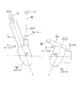
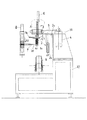
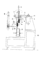
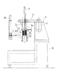
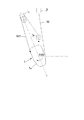
図1は、上記第1の被巻線部材及び上記第2の被巻線部材が第1の巻枠及び第2の巻枠からなる実施例のコイル巻線装置と、巻線されたコイルを受け取ってモータの固定子スロットに挿入するコイル挿入装置との概略構成を模式的に示す正面図である。
基台10の上部に水平状態に設けられた基板11には、図で垂直方向の回転軸線X1,X2を有する第1の巻枠1及び第2の巻枠2が水平方向(図で左右方向)に移動可能に設けられている。また、基板11の図で左側には移動した第1の巻枠1及び第2の巻枠2をそれぞれ回転させる回転母体3が回転自在に設けてあり、回転駆動モータ4によりタイミングベルト5を介してノズル7の移動方向に平行な軸線Xの回りに往復回転可能に駆動される。そして、第2の巻枠2の巻線部は第1の巻枠1の巻線部に対して、少なくとも第1の巻枠1の回転軸線X1に沿う巻線長だけノズル7の移動方向(図では下方)にずらせて配設されており、第1の巻枠1は巻枠上下動モータ6により上下動する。
[Example 1]
FIG. 1 shows a coil winding device of an embodiment in which the first and second wound members are composed of a first winding frame and a second winding frame, and a wound coil. It is a front view which shows typically schematic structure with the coil insertion apparatus which receives and inserts into the stator slot of a motor.
On the
第1,第2の巻枠1,2の左方には、帯状に並列した複数本のワイヤWを上記第1,第2の巻枠1,2に供給するノズル7が設けてあり、ワイヤWに直交する移動方向(軸線Xに平行な方向:図で上下方向)にノズル駆動モータ8によりボールねじ機構等を介して往復駆動される。なお、ノズル7は、離散した複数本のワイヤをワイヤ投入口から挿入して帯状に並列した複数本のワイヤに整形し、適当なテンションを与えてワイヤ排出口から供給するようにした公知のワイヤ供給手段である。
このような構成からなるコイル巻線装置の図で下方には、基台10に設けられ図示しない駆動手段により、垂直方向に昇降可能であり、巻線しようとするモータの極数に応じてインデックス回転可能な周知のコイル挿入治具9が設けてある。
On the left side of the first and
In the figure of the coil winding device having such a configuration, the lower part is vertically movable by a drive means (not shown) provided on the
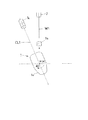
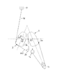
図2は第1の巻枠1及び第2の巻枠2の概略形状を示す平面図であり、コイル巻線開始時の位置を示している。第1の巻枠1は、巻枠本体1aと、ノズル7から供給される帯状に並列した複数本のワイヤW(図2では1本のみを示している)の巻き始め線W1を把持するグリッパ1bと、巻き始め線W1の長さを設定する巻き始め線ガイド1cと、これらを一体に固設する第1の巻枠基板1dとからなり、回転軸線X1の回りに回転する。
FIG. 2 is a plan view showing a schematic shape of the
また、第2の巻枠2は、巻枠本体2aと、ワイヤWの渡り線W2(図12参照)の長さを設定するガイドピン2bと、重錘2cと、これらを一体に固設する第2の巻枠基板2dとからなり、重錘2cは、第2の巻枠2が図2で左方に移動して第1の巻枠1と一体となってさらに同方向に移動し、第2の巻枠2の回転軸線X2の位置が移動前の第1の巻枠1の回転軸線X1の位置となり、第1,第2の巻枠1,2が一体となって回転軸X2の回りに回転するとき、その一対の巻枠の回転バランスをとるためのものである。また、巻枠本体1a,2aの平面図における長手方向の中心線CL1及びCL2は、コイル巻線が終了してコイル挿入治具9に挿入された状態で、図15に示すように、コイル挿入治具9の中心線上で交わるようにその交差角が設定されている。
Further, the
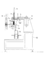
次に、このような構成からなるコイル巻線装置を用いて第1,第2の巻枠1,2に連続して巻線するコイル巻線方法を図1及び図3〜図8に示す正面図と、図2及び図9〜図15に示す平面図を参照して詳細に説明する。これらの各図においては、図を簡略化して分かりやすくするため、図1及び図3〜図8においては、第1の巻枠1は巻枠本体1aとグリッパ1bのみを、第2の巻枠2は巻枠本体2aと重錘2cのみを示し、図9〜図15においては、第1,第2の巻線基板1d,2d及び重錘2cは省略し、特に図9〜図11では、離間して不作動状態にある第2の巻枠2も省略してある。
Next, a coil winding method for continuously winding the first and second winding
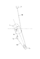
図1に示すように、第1の巻枠1の回転軸線X1の位置が回転母体3の軸線Xの位置にあり、第2の巻枠2が第1の巻枠1からその回転軸線X1と直交する方向に離間した位置にある状態で、図1において最上位に位置するノズル7から供給されるワイヤWの図9に示す巻き始め線W1を第1の巻枠1のグリッパ1bに把持させて預け、第1の巻枠1だけを図9で矢示A1方向(時計方向)へ回転させながらノズル7を図1で下方へ移動させ、巻枠本体1aにワイヤWを螺旋状に巻線して第1のコイルC1を形成する(図3参照)。このとき、図10及び図11に示すように、ワイヤWの巻き始め線W1は巻き始め線ガイド1cによってその長さを所定の値に設定されてから巻枠本体1aにワイヤWが巻線される。
As shown in FIG. 1, the position of the rotation axis X1 of the
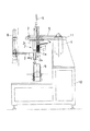
第1のコイルC1の巻線が終わると、第1の巻枠1の回転を停止させると共に、ノズル7をさらに僅かに下降させる。同時に、第2の巻枠2を図4の軸線X及び回転軸線X1に直交する矢示A2方向(左方向)に搬送して第1の巻枠1に連結させ、一体的に連結した状態でさらに矢示A2方向へ搬送し、第2の巻枠2の回転軸X2の位置を、第1の巻枠1の移動前の回転軸X1の位置、すなわち回転母体3の回転軸Xの位置に移行させて図4及び図12に示す状態とする。この状態で第2の巻枠2を第1の巻枠1と一体に回転軸X2(回転軸Xと同位置)の回りに矢示A3方向(反時計方向)に半回転させると、図5及び図13に示す状態となり、第1のコイルC1から第2のコイルC2(図6参照)への渡り線W2が、図13に示すように、第2の巻枠2の渡り線ガイドピン2bによって長さを設定される。
When the winding of the first coil C1 is finished, the rotation of the first winding
その後、第2の巻枠2を第1の巻枠1と一体のまま回転軸X2の回りに矢示A3方向に回転させながらノズル7を下降させると、第2の巻枠2の巻枠本体2aにワイヤWが螺旋状に巻線されて第2のコイルC2が形成され、図6及び図14に示す状態となる。これにより、第1のコイルC1から渡り線W2をカットすることなく連続して第2のコイルC2をよじれなく巻線することができる。
Thereafter, when the
第1,第2のコイルC1,C2の巻線が終了すると、コイル挿入治具9を図7の矢示A4方向(上方向)に上昇させて第2のコイルC2をコイル挿入治具9に挿入し、次いで第1の巻枠1を巻枠上下動モータ6によって図8の矢示A5方向(下方向)に下降させて、第1のコイルC1をコイル挿入治具9に挿入する(図15参照)。第1,第2のコイルC1,C2のコイル挿入治具9への挿入が終わると、巻き終わり線W3を所定の長さに切断し、コイル挿入治具9を下降させた後、巻線しようとする固定子の極数に対応して所定角度インデックス回転させる。
同様にして、第3,第4の一対のコイルを連続巻線してコイル挿入治具9に挿入し、所定極数の対のコイルがすべて巻線されてコイル挿入治具9に挿入された後、図示しない固定子のスロットに挿入される。
When the winding of the first and second coils C1 and C2 is completed, the
Similarly, the third and fourth pairs of coils are continuously wound and inserted into the
このように、この実施例のコイル巻線装置を使用したコイル巻線方法によれば、第1,第2の巻枠1,2に一対のコイルをカットすることなく連続してよじれなく巻線することができるため、簡単な方法で各コイルの端末線の本数が半減してその処理が容易になると同時に、コイル巻線の稼働率も向上する。また、連続巻線した一対のコイル間の渡り線も短くなる。
さらに、第2の巻枠2に重錘2cを付加することにより、第2の巻枠2が第1の巻枠1と一体的に回転したときのバランスをとることができ、高速巻線が可能になる。なお、この実施例において、第1,第2の巻枠1,2は随時交換することができ、第1,第2の巻枠1,2に代えて固定子のコアを形成する第1,第2のコアに直接巻線することも可能である。
Thus, according to the coil winding method using the coil winding apparatus of this embodiment , the first and second winding
Furthermore, by adding a
この発明によるコイル巻線方法及びコイル巻線装置は、家庭用電気製品や自動車等に用いられる各種モータの固定子スロットに挿入可能なコイルの巻線に適用できる。そして、複数のコイル間の渡り線を切断することなく、一対のコイルを連続してよじれなく巻線することができる。そのため、端末線の本数が減少して巻線後の端末線の処理が容易になると共に、渡り線の長さも短くすることができる。 The coil winding method and the coil winding apparatus according to the present invention can be applied to coil windings that can be inserted into stator slots of various motors used in household electrical appliances and automobiles. And a pair of coils can be wound continuously without twisting, without cutting the connecting wire between a plurality of coils. For this reason, the number of terminal wires is reduced, the processing of the terminal wires after winding is facilitated, and the length of the jumper wires can be shortened.
1:第1の巻枠(第1の被巻線部材) 1a:巻枠本体 1b:グリッパ
2:第2の巻枠(第2の被巻線部材) 2a:巻枠本体 2c:重錘
3:回転母体 7:ノズル 9:コイル挿入治具 10:基台 11:基板
21:第1のコア(第1の被巻線部材) 22:第2のコア(第2の被巻線部材)
W:ワイヤ W1:巻き始め線 W2:渡り線 W3:巻き終わり線
1: 1st winding frame (first wound member) 1a: winding
W : Wire W1: Winding start line W2: Crossover W3: Winding end line
Claims (5)
前記第2の被巻線部材を、前記第1の被巻線部材からその回転軸線(X1)と直交する方向に離間し、且つ少なくとも該回転軸線(X1)に沿う巻線長だけ前記ノズルの移動方向にずれた位置に配置して、前記第1の被巻線部材だけを前記回転軸線(X1)の回りに回転させて該第1の被巻線部材に第1のコイルを巻線した後、
前記第2の被巻線部材をその回転軸線(X2)に直交する方向に移動させて前記第1の被巻線部材に連結させ、さらに該第1の被巻線部材と共に移動させて該第2の被巻線部材の回転軸線(X2)を前記第1の被巻線部材の移動前の回転軸線(X1)の位置に移行させ、該第2の被巻線部材を前記回転軸線(X2)の回りに前記第1の被巻線部材と一体的に回転させて、該第2の被巻線部材に第2のコイルを巻線することを特徴とするコイル巻線方法。 A plurality of wires in parallel to the strip, supplied from the movable nozzle in a direction perpendicular to the wire, the first of the winding member and a rotating around parallel axes of rotation in the direction of movement of the nozzle A coil winding method in which two wound members are wound sequentially and continuously,
The second member to be wound is spaced apart from the first member to be wound in a direction perpendicular to the rotation axis (X1), and at least the winding length along the rotation axis (X1) is the length of the nozzle. Arranged at a position shifted in the moving direction, only the first wound member is rotated around the rotation axis (X1) , and the first coil is wound around the first wound member . rear,
The second member to be wound is moved in a direction perpendicular to the rotation axis (X2) to be connected to the first member to be wound , and further moved together with the first member to be wound. 2 of the winding member axis of rotation (X2) is shifted to the position of the first before movement of the winding member rotational axis (X1), the axis of rotation of the second of the winding member A coil winding method , wherein the second coil is wound around the second wound member by rotating integrally with the first wound member around (X2) .
前記第1の被巻線部材及び第2の被巻線部材はそれぞれ前記軸線(X)と直交する方向に移動可能であって、前記第2の被巻線部材は、前記第1の被巻線部材に対して少なくとも該第1の被巻線部材の前記回転軸線(X1)の方向に沿う巻線長だけ前記ノズルの移動方向にずれた位置に配置されており、
前記第1の被巻線部材の回転軸線(X1)が前記軸腺(X)の位置にあり、前記第2の被巻線部材が前記第1の被巻線部材からその回転軸線(X1)と直交する方向に離間した位置にある状態で、前記第1の被巻線部材だけを前記回転母体によって前記回転軸線(X1)の回りに回転させながら前記ノズルを前記移動方向へ移動させることによって、該ノズルから供給される複数本のワイヤによって該第1の被巻線部材に第1のコイルを巻線し、
前記第2の被巻線部材を前記軸線(X)と直交する方向に移動させて前記第1の被巻線部材に連結させ、該第2の被巻線部材の回転軸(X2)を前記軸線(X)の位置に移行させた状態で、該第2の被巻線部材を前記回転母体によって前記回転軸(X2)の回りに前記第1の被巻線部材と一体的に回転させながら前記ノズルを前記移動方向へさらに移動させることによって、該ノズルから供給される複数本のワイヤによって該第2の被巻線部材に第2のコイルを連続して巻線し得るように構成したことを特徴とするコイル巻線装置。 Supplying a plurality of wires in parallel to the strip, and the nozzle movable in a direction perpendicular to the feed direction of the wire, the rotation matrix which is driven to rotate about an axis parallel glands in the moving direction of the nozzle (X) And a first wound member and a second wound member each having a rotation axis (X1, X2) parallel to the axis (X) ,
The first and second wound members are respectively movable in a direction perpendicular to the axis (X), and the second wound member is the first wound member. It is arranged at a position shifted in the moving direction of the nozzle by at least the winding length along the direction of the rotation axis (X1) of the first wound member with respect to the wire member ,
The rotation axis (X1) of the first wound member is at the position of the axis gland (X), and the second wound member is rotated from the first wound member to the rotation axis (X1). By moving the nozzle in the moving direction while rotating only the first wound member around the rotation axis (X1) by the rotating base body in a state of being spaced apart in a direction orthogonal to Winding a first coil around the first member to be wound by a plurality of wires supplied from the nozzle;
The second wound member is moved in a direction perpendicular to the axis (X) to be connected to the first wound member, and the rotation axis (X2) of the second wound member is While being moved to the position of the axis (X), the second wound member is rotated integrally with the first wound member around the rotation axis (X2) by the rotating base. by further moving the nozzle to the moving direction that was configured to be able to winding continuously a second coil to be wound member of the second by a plurality of wires fed from the nozzle Coil winding device characterized by the above.
前記第2の被巻線部材が、巻枠本体と、前記ワイヤの渡り線の長さを設定するガイドピンと、前記第2の巻枠が前記第1の巻枠と一体となって回転するときにその一対の巻枠の回転バランスをとるための重錘とを一体に設けた第2の巻枠である請求項4記載のコイル巻線装置。 The first member to be wound includes a winding body, a gripper that grips winding start lines of a plurality of wires supplied from the nozzle, and a winding start line guide that sets a length of the winding start line. Is a first reel provided integrally with
When the second wound member rotates integrally with the first reel, the reel body, the guide pin for setting the length of the wire crossover, and the second reel. 5. The coil winding device according to claim 4, wherein the second winding frame is integrally provided with a weight for balancing the rotation of the pair of winding frames .
Priority Applications (1)
| Application Number | Priority Date | Filing Date | Title |
|---|---|---|---|
| JP2004235365A JP4611684B2 (en) | 2004-08-12 | 2004-08-12 | Coil winding method and coil winding apparatus |
Applications Claiming Priority (1)
| Application Number | Priority Date | Filing Date | Title |
|---|---|---|---|
| JP2004235365A JP4611684B2 (en) | 2004-08-12 | 2004-08-12 | Coil winding method and coil winding apparatus |
Publications (2)
| Publication Number | Publication Date |
|---|---|
| JP2006054967A JP2006054967A (en) | 2006-02-23 |
| JP4611684B2 true JP4611684B2 (en) | 2011-01-12 |
Family
ID=36032050
Family Applications (1)
| Application Number | Title | Priority Date | Filing Date |
|---|---|---|---|
| JP2004235365A Expired - Lifetime JP4611684B2 (en) | 2004-08-12 | 2004-08-12 | Coil winding method and coil winding apparatus |
Country Status (1)
| Country | Link |
|---|---|
| JP (1) | JP4611684B2 (en) |
Families Citing this family (5)
| Publication number | Priority date | Publication date | Assignee | Title |
|---|---|---|---|---|
| JP5312157B2 (en) * | 2009-04-03 | 2013-10-09 | 三工機器株式会社 | Coil winding method and coil winding apparatus |
| JP5661831B2 (en) * | 2013-02-26 | 2015-01-28 | ファナック株式会社 | Winding insertion machine that inserts a coil without kinking of wire into the stator |
| KR102021662B1 (en) * | 2017-09-19 | 2019-09-16 | 김동섭 | motor coil winding apparatus to array multi coil and its method |
| JP7536627B2 (en) | 2020-12-14 | 2024-08-20 | Nittoku株式会社 | Winding device and winding method |
| KR102664482B1 (en) * | 2021-10-15 | 2024-05-14 | 주식회사 야호텍 | Insert tool with adjusted blade position |
Family Cites Families (6)
| Publication number | Priority date | Publication date | Assignee | Title |
|---|---|---|---|---|
| JPH0530060Y2 (en) * | 1988-09-05 | 1993-07-30 | ||
| JPH11289723A (en) * | 1998-04-03 | 1999-10-19 | Hitachi Ltd | Apparatus and method for manufacturing stator of rotating electric machine |
| JP4382182B2 (en) * | 1999-01-14 | 2009-12-09 | 三工機器株式会社 | Winding method and winding device |
| JP4530493B2 (en) * | 2000-06-26 | 2010-08-25 | 株式会社東郷製作所 | Manufacturing method of coil unit for rotating machine |
| JP4085698B2 (en) * | 2002-05-30 | 2008-05-14 | 日産自動車株式会社 | Winding method and winding device |
| US7011266B2 (en) * | 2002-08-08 | 2006-03-14 | Aisin Aw Co., Ltd. | Coil forming device and coil forming method |
-
2004
- 2004-08-12 JP JP2004235365A patent/JP4611684B2/en not_active Expired - Lifetime
Also Published As
| Publication number | Publication date |
|---|---|
| JP2006054967A (en) | 2006-02-23 |
Similar Documents
| Publication | Publication Date | Title |
|---|---|---|
| EP3618245B1 (en) | Method and device for inserting insulating sleeves into wiring slots of flat wire motor stator | |
| US7770286B2 (en) | Manufacturing method for a winding assembly of a rotary electrical machine | |
| US5864940A (en) | Method for producing a winding of a stator coil | |
| CN101989777B (en) | Motor and method of manufacturing motor | |
| CN111615781B (en) | Method for producing a continuous strip winding for an electric machine | |
| CN112703665A (en) | Method for providing a hairpin element for a winding of an electric machine | |
| JP4611684B2 (en) | Coil winding method and coil winding apparatus | |
| KR102021662B1 (en) | motor coil winding apparatus to array multi coil and its method | |
| JP5312157B2 (en) | Coil winding method and coil winding apparatus | |
| CN100413185C (en) | Loop forming and inserting device and loop forming and inserting method | |
| JP5942236B1 (en) | Coil unit array device | |
| JP2005102402A (en) | Stator manufacturing device | |
| KR102636432B1 (en) | wire alignment device for motor coil | |
| JPH1198779A (en) | Wire twist prevention device in winding machine | |
| KR102310393B1 (en) | simultaneous motor coil winding apparatus to array multi coil and its method | |
| JP5768305B1 (en) | Stator manufacturing method and apparatus | |
| JP4084083B2 (en) | Method and apparatus for winding stator core | |
| JP4456053B2 (en) | Coil winding system and winding method | |
| JP4401093B2 (en) | Winding device | |
| CN216122145U (en) | Stator winding device of shaded pole motor | |
| JP4158973B2 (en) | Method and apparatus for winding stator core | |
| EP1111760A2 (en) | Apparatus and methods for winding dynamo-electric machine stators with parallel wires | |
| JP3621079B2 (en) | Multi-pole armature winding method and winding device | |
| CN121461695A (en) | Winding and wire embedding equipment and winding and wire embedding method | |
| CN119654778A (en) | Arrangement of a wire winding in a magnetizable flux conductor of a stator of a rotating electrical machine designed as an inner rotor |
Legal Events
| Date | Code | Title | Description |
|---|---|---|---|
| A621 | Written request for application examination |
Free format text: JAPANESE INTERMEDIATE CODE: A621 Effective date: 20070412 |
|
| A977 | Report on retrieval |
Free format text: JAPANESE INTERMEDIATE CODE: A971007 Effective date: 20100218 |
|
| A131 | Notification of reasons for refusal |
Free format text: JAPANESE INTERMEDIATE CODE: A131 Effective date: 20100223 |
|
| A521 | Request for written amendment filed |
Free format text: JAPANESE INTERMEDIATE CODE: A523 Effective date: 20100426 |
|
| TRDD | Decision of grant or rejection written | ||
| A01 | Written decision to grant a patent or to grant a registration (utility model) |
Free format text: JAPANESE INTERMEDIATE CODE: A01 Effective date: 20101012 |
|
| A01 | Written decision to grant a patent or to grant a registration (utility model) |
Free format text: JAPANESE INTERMEDIATE CODE: A01 |
|
| A61 | First payment of annual fees (during grant procedure) |
Free format text: JAPANESE INTERMEDIATE CODE: A61 Effective date: 20101014 |
|
| FPAY | Renewal fee payment (event date is renewal date of database) |
Free format text: PAYMENT UNTIL: 20131022 Year of fee payment: 3 |
|
| R150 | Certificate of patent or registration of utility model |
Ref document number: 4611684 Country of ref document: JP Free format text: JAPANESE INTERMEDIATE CODE: R150 |
|
| R250 | Receipt of annual fees |
Free format text: JAPANESE INTERMEDIATE CODE: R250 |
|
| R250 | Receipt of annual fees |
Free format text: JAPANESE INTERMEDIATE CODE: R250 |
|
| R250 | Receipt of annual fees |
Free format text: JAPANESE INTERMEDIATE CODE: R250 |
|
| R250 | Receipt of annual fees |
Free format text: JAPANESE INTERMEDIATE CODE: R250 |
|
| EXPY | Cancellation because of completion of term |