JP2004282941A - Winding device - Google Patents
Winding device Download PDFInfo
- Publication number
- JP2004282941A JP2004282941A JP2003073310A JP2003073310A JP2004282941A JP 2004282941 A JP2004282941 A JP 2004282941A JP 2003073310 A JP2003073310 A JP 2003073310A JP 2003073310 A JP2003073310 A JP 2003073310A JP 2004282941 A JP2004282941 A JP 2004282941A
- Authority
- JP
- Japan
- Prior art keywords
- winding
- electric wire
- rotating plate
- frame
- bobbin
- Prior art date
- Legal status (The legal status is an assumption and is not a legal conclusion. Google has not performed a legal analysis and makes no representation as to the accuracy of the status listed.)
- Granted
Links
Images


Classifications
-
- Y—GENERAL TAGGING OF NEW TECHNOLOGICAL DEVELOPMENTS; GENERAL TAGGING OF CROSS-SECTIONAL TECHNOLOGIES SPANNING OVER SEVERAL SECTIONS OF THE IPC; TECHNICAL SUBJECTS COVERED BY FORMER USPC CROSS-REFERENCE ART COLLECTIONS [XRACs] AND DIGESTS
- Y02—TECHNOLOGIES OR APPLICATIONS FOR MITIGATION OR ADAPTATION AGAINST CLIMATE CHANGE
- Y02T—CLIMATE CHANGE MITIGATION TECHNOLOGIES RELATED TO TRANSPORTATION
- Y02T10/00—Road transport of goods or passengers
- Y02T10/60—Other road transportation technologies with climate change mitigation effect
- Y02T10/64—Electric machine technologies in electromobility
Abstract
Description
【0001】
【発明の属する技術分野】
本発明は、複数本の電線を並列して巻枠に巻き付けてコイルを形成するようにした巻線装置に関する。
【0002】
【従来の技術】
近年、電気自動車などのモータの開発に際し、自動車に搭載可能な低電圧の電源によって大きな駆動力が得られるようにするため、電線の断面積を大きくして大電流を流すことにより、大きな駆動力が得られるようにしたモータが望まれている。しかしながら、電線の直径を大きくした場合には、巻線操作やステータコアへのコイル挿入操作が困難となると共に、ステータコアのスロット内における電線のスペースファクタ(空間占有率)も小さくなるという問題点があった。
【0003】
そこで、複数本の電線を並列して巻いて(パラ巻きして)コイルを形成することにより、巻線操作やコイル挿入操作に支障をきたすことなく、電線の断面積を実質的に大きくするようにした巻線装置及び方法が提案されている。このようなパラ巻線においては、従来の巻線装置で用いられているフライヤーと呼ばれる回転ノズルを用いることはできない。すなわち、電線を送出するノズルを巻枠の周りで回転させて、電線を巻枠に巻き付けるフライヤーを用いると、複数本の電線が縄のように捩れてしまい、得られたコイルを後の工程でコイル挿入装置によりステータコアのスロットに挿入することが困難になってしまうからである。
【0004】
このため、例えば、下記特許文献1には、巻枠への素線の巻き付けによる巻線形成、及び、巻枠からの巻線の取外しを繰り返すことにより、互いに連結された所定数の極の巻線を形成する巻線製造システムにおいて、回転する巻枠に素線を巻き付けて巻線を形成する巻線形成手段と、巻き付けが完了し巻枠から取り外された巻線を、その巻線の極に対応する所定の保持位置に保持する巻線保持手段と、前記巻枠の回転に合わせて前記巻線保持手段を動かすことにより、前記巻線保持手段に保持された巻線と、他の極の巻線を形成中の巻枠との相対位置関係の乖離を抑制する相対位置維持手段と、を含むことを特徴とする巻線製造システムが開示されている。
【0005】
また、下記特許文献2には、回転する巻枠を上方に配置し、ステータコアの内歯に対応して立設された複数本のガイド棒を有し、前記巻枠と同期して回転できる電線保持治具を下方に配置し、前記電線保持治具又は前記巻枠を昇降可能とすると共に、前記電線保持治具を水平方向に移動可能とし、前記電線保持治具の中心部が前記巻枠の回転中心下方に位置するように前記電線保持治具を配置し、ノズルから並列して引き出された複数本の電線を前記巻枠に保持させ、その状態で前記巻枠と前記電線保持治具とを同期して回転させ、前記電線を前記巻枠に所定回数巻き付けてコイルを形成し、前記電線保持治具を水平方向に移動させて前記ガイド棒の所定の間隙に前記巻枠に保持されたコイルが挿入されるように位置決めし、前記電線保持治具又は前記巻枠を昇降させて前記コイルを前記ガイド棒の所定の間隙に受け入れて保持させ、再び前記電線保持治具の中心部が前記巻枠の回転中心下方に位置するように前記電線保持治具を配置して巻線するという前記一連の工程を複数回繰り返すことにより、並列した複数本の電線からなる多極のコイルを連続的に形成することを特徴とする巻線方法が開示されている。
【0006】
【特許文献1】
特開2001−297935号公報
【特許文献2】
特開2000−209822号公報
【0007】
【発明が解決しようとする課題】
しかしながら、上記特許文献1、2に記載された巻線装置及び方法では、巻枠と電線保持治具とを同期して回転させ、巻枠に電線を所定回数巻き付けてコイルを形成すると、そのコイルを電線保持具に受け渡し、再び巻枠と電線保持具とを回転させて巻線を行うようにしているので、巻線操作が終了する度に電線保持具にコイルを受け渡さなければならず、多極のコイルを連続的に形成することができるものの、巻線作業に時間がかかって生産性が悪いという問題があった。
【0008】
したがって、本発明の目的は、複数本の電線を並列して巻枠に巻き付けてコイルを形成する作業を繰り返すことにより、多極のコイルを連続的に形成するようにした巻線装置において、1つのコイルの巻線から次のコイルの巻線に至る作業時間を短縮して、生産性を高めることができるようにした巻線装置を提供することにある。
【0009】
【課題を解決するための手段】
上記目的を達成するために、本発明の巻線装置は、複数本の電線を並列して巻枠に巻き付けてコイルを形成する作業を繰り返すことにより、多極のコイルを連続的に形成するようにした巻線装置において、複数本の電線を並列させて供給する電線供給手段と、複数の巻枠が取付けられた回転板と、選択された巻枠を回転板に対して突出させる巻枠スライド手段とを備え、前記巻枠スライド手段によって、前記巻枠を前記回転板に対して選択的に突出させ、前記回転板を回転させることにより、前記電線供給手段によって供給される複数本の電線が、前記突出した巻枠に巻き付けられるように構成されていることを特徴とする。
【0010】
本発明の巻線装置によれば、巻枠スライド手段によって巻枠を回転板に対して選択的に突出させ、その状態で回転板を回転させることにより、並列された複数本の電線が突出した巻枠に巻き付いてコイルが形成される。そして、1つの巻枠に対する巻線が終了したら、その巻枠を引き込めて、次の巻枠を突出させ、その状態で回転板を回転させることにより、並列された複数本の電線が次の巻枠に巻き付いてコイルが形成される。このような操作を繰り返すことにより、パラ巻きされた多極のコイルを連続的に形成することができる。
【0011】
そして、必要とされる全ての巻枠に巻線を施した後、コイルトランスファー治具や、コイルインサーター治具などに、巻線されたコイルを一度に移し渡すことができるので、巻線が終了した都度、電線保持具にコイルを受け渡す必要がなくなり、巻線作業時間を大幅に短縮して、生産性を高めることができる。
【0012】
本発明の巻線装置において、前記電線供給手段は、複数本の電線を一列に並べて送出するガイドノズルを有し、前記回転板が回転するとき、前記突出した巻枠と前記ガイドノズルとの距離がほぼ一定に保たれるように、前記電線の走行方向に沿って往復移動するように構成されていることが好ましい。
【0013】
本発明の巻線装置では、回転板上に取付けられた複数の巻枠のうち、巻線を施そうとする巻枠のみを巻枠スライド手段によって突出させ、この突出した巻枠に対して巻線を行うのであるが、回転板の回転中心に対して突出した巻枠は偏心した位置にある。このため、回転板と一緒に回転する前記突出した巻枠と、電線供給手段のガイドノズルとの距離は、巻枠の回転位置によって変化することになる。このため、両者の距離が短くなったときに電線のたるみが生じて、巻枠に巻き付く電線の配列が乱れる原因となる。そこで、上記態様のように、回転板の回転に伴って、前記ガイドノズルを電線の走行方向に沿って往復移動させ、突出した巻枠とガイドノズルとの距離をほぼ一定に保つことにより、電線のたるみの発生を防止して、巻枠に巻き付く電線の配列が乱れることを防止できる。
【0014】
また、前記ガイドノズルは、前記電線の走行方向と、前記巻枠のスライド方向とに移動可能に取付けられていることが好ましい。
【0015】
この態様によれば、巻線操作中に、ガイドノズルを電線の走行方向に沿って往復移動させることによって、上記のように電線のたるみを防止できる。また、巻線操作中に、ガイドノズルを巻枠のスライド方向に動かすことによって、電線を整列させて巻き付けることができる。更に、巻枠のスライドに伴って電線のガイドノズルを動かすことができる。
【0016】
更に、前記回転板には、前記電線の巻き始めの端部を保持すると共に、巻枠から巻枠に移る渡り線を引き掛けるための複数本の引っ掛け棒が取付けられており、これらの引っ掛け棒の先端部は、引き掛けられた前記電線が外れないように拡径されていて、前記突出した巻枠の電線巻き付け位置よりも低い高さとされていることが好ましい。
【0017】
この態様によれば、各巻枠への巻線操作の開始前に、電線の始端部や渡り線部を上記引っ掛け棒に引っ掛けることによって、電線の始端部や渡り線部の長さを適度な長さにして確保することができる。また、引っ掛け棒は、突出した巻枠の電線巻き付け位置よりも低い高さとされているので、巻枠への電線の巻き付け操作を邪魔することはなく、しかも引っ掛け棒の先端部が拡径されているので、巻線を施すべき巻枠の突出に併せて、電線供給手段を移動させたとき、電線が引っ掛け棒から外れてしまうことを防止できる。
【0018】
【発明の実施の形態】
図1〜10には、本発明による巻線装置の一実施形態が示されている。
【0019】
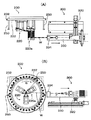
図1は同巻線装置の斜視図、図2は同巻線装置の正面図、図3は同巻線装置の平面図、図4は同巻線装置の側断面図である。図5〜14は同巻線装置による巻線操作の手順を示す説明図であって、いずれも(A)は平面図、(B)は正面図である。
【0020】
図1〜4に示すように、この巻線装置100は、基台110上に設置された巻線装置本体200と、電線供給手段300とを備えている。
【0021】
巻線装置本体200は、基台110上に立設された枠状のフレーム210を有している。このフレーム210は、前後の支持板211、212と、これらの支持板211,212を連結する複数本のガイド棒213を有している。
【0022】
これらのガイド棒213には、スリーブ214及びフランジ215を介して、複数枚、この実施形態の場合4枚のスライド枠216が、ガイド棒213の軸方向に位置をずらして取付けられている。そして、各フランジ215と、フレーム210との間には、エアシリンダ217がそれぞれ配置されている。このエアシリンダ217によって、スライド枠216がガイド棒213に沿ってスライドするようになっている。
【0023】
スライド枠216の内周には、クロスローラベアリング218を介して、巻枠支持板221が回転可能に取付けられている。また、前方の支持板211も枠状をなしており、この枠状の支持板211の内周に、クロスローラベアリング218を介して、回転板222が回転可能に取付けられている。なお、ここでクロスローラベアリング218は、スライド枠216又は支持板211に対して、巻枠支持板221又は回転板222を回転可能に保持する構造をなしている。したがって、巻枠支持板221は、スライド枠216に対して回転可能とされると共に、スライド枠216がガイド棒213に沿ってスライドすると、それと一緒にスライドするようになっている。
【0024】
特に図4に示すように、各巻枠支持板221には、スライド方向に伸びる2本の巻枠支軸223がそれぞれ取付けられている。巻枠支軸223は、それよりも前方に位置する巻枠支持板221と、回転板222とを貫通して前方に突出するように伸びている。そして、各巻枠支持板221から伸びる巻枠支軸223の先端には、巻枠220が取付けられている。巻枠220は、巻枠支軸223の先端に固着されたベース板224と、このベース板224上に立設された2枚の枠板225、226とで構成されている。
【0025】
したがって、エアシリンダ217が作動して、スライド枠216がガイド棒213に沿ってスライドすると、クロスローラベアリング218を介して連設された巻枠支持板221が一緒にスライドし、この巻枠支持板221に巻枠支軸223を介して連結された対応する巻枠220が、回転板222に対して突出したり引き込んだりする。
【0026】
なお、上記ガイド棒213、スリーブ214、フランジ215、スライド枠216、クロスローラベアリング218、巻枠支持板221、巻枠支軸223が、本発明における巻枠スライド手段を構成している。
【0027】
また、この実施形態の場合、スライド枠216及び巻枠支持板221が合計4組設けられているが、実際にはそのうちの3組に取付けられた巻枠支軸223に巻枠220が装着されており、最後部に位置する1組のスライド枠216及び巻枠支持板221の巻枠支軸223には、巻枠は取付けられておらず、仕様の変更などによって4つの巻枠が必要になったときに使うための予備とされている。
【0028】
また、後方の支持板212の中心と、前方の回転板222の中心との間には、回転軸230が配置されている。回転軸230は、支持板212に対しては回転可能に取付けられ、回転板222に対してはそれと一体に回転するように固着されている。更に、この回転軸230の外周には、スプライン溝231が形成されており、前記巻枠支持板221の中心には、このスプライン溝231に嵌合する溝を内周に有するスリーブ227が装着され、このスリーブ227を通して前記回転軸230が挿通されている。
【0029】
このため、回転軸230が回転すると、上記巻枠支持板221も一体に回転するようになっている。更に、巻枠支持板221と共に、巻枠支軸223も一体に回転し、巻枠220が一体に回転するようになっている。
【0030】
また、回転板222の前面側の外周には、環状の大径ギヤ232が取付けられており、大径ギヤ232は、回転板222と一体に回転する。そして、フレーム210にはモータ240が取付けられており、このモータ240の駆動ギヤ241が上記大径ギヤ232と歯合している。
【0031】
したがって、モータ240の作動によって、駆動ギヤ241を介して大径ギヤ232及び回転板222が回転し、回転軸230のスプライン溝231にスリーブ227を介して嵌合する、それぞれの巻枠支持板221も一体に回転し、更に巻枠支持板221から延出されて、その前方に位置する巻枠支持板221及び回転板222を貫通する巻枠支軸223及び巻枠220も一体に回転するようになっている。
【0032】
更に、大径ギヤ232の周縁部には、電線Wの引っ掛け棒250が所定間隔で立設されている。この引っ掛け棒250は、エアシリンダ217によって突出された巻枠220への巻線操作に干渉しない高さとされており、その先端部には、引っ掛けた電線Wが滑り抜けて外れないようにするための拡径部251が形成されている。
【0033】
次に、電線供給装置300は、基台110上に立設された支柱310を介して水平に支持された基板311を有し、この基板311は、回転円板222の側方にあって、巻枠220方向に向けて伸びている。この基板311には、その長手方向に沿ってスライド可能に第1スライド板320が取付けられている。第1スライド板320は、基板311の長手方向と直交する方向に伸びる細長い板状をなしている。第1スライド板320は、基板311上に設置されたボールネジに螺合し、図示しないサーボモータによって、図1、3中の矢印X方向に移動するようになっている。
【0034】
また、第1スライド基板320の長手方向に沿ってスライド可能に第2スライド板330が取付けられている。第2スライド板330は、第1スライド板320と直交する方向(基板311の長手方向)に伸びる細長い板状をなしている。第2スライド板330は、第1スライド板320上に設置されたボールネジに螺合し、図示しない上記とは別のサーボモータによって、図1、3中の矢印Y方向に移動するようになっている。
【0035】
そして、この第2スライド板330上には、図示しない電線リールから繰り出される複数本の電線Wを導入する第1ガイド部材331と、この第1ガイド板部材331を通った複数本の電線Wを更に集束させる第2ガイド部材332と、この第2ガイド部材332を通った複数本の電線Wを一列に配列させる第3ガイド部材333と、この第3ガイド部材333を通った複数本の電線Wを一列に配列された状態で送出させるガイドノズル334が設置されている。
【0036】
第1ガイド部材331には、複数のローラが並んで支持されており、個々の電線Wは、これらのローラ群にジグザグに通されて曲がりくせを矯正されるようになっている。第2ガイド部材332は、個々の電線Wを通す複数の孔を有する板で構成されている。第3ガイド部材333は、集束された電線Wを一列に並べるように挟持するスリット状の孔を有する部材で構成されている。ガイドノズル334は、電線Wを重ならないように一列に並べて送出するスリットを有する部材で構成されている。
【0037】
そして、第1スライド板320は、基板311に沿ってX方向に移動し、第2スライド板330は、第1スライド板320に沿ってY方向に移動するため、第2スライド板330上に設置された上記ガイドノズル334は、図1、3中のX−Y方向に移動できるようになっている。この場合、X方向は電線Wの走行方向であり、Y方向は巻枠220のスライド方向である。
【0038】
次に、図5〜14に基づいて、上記巻線装置100による巻線方法について説明する。
【0039】
図5は、同巻線装置による巻線開始時の状態を示している。このとき、巻枠220はいずれも回転板222に近接して引き込んだ状態をなしている。また、ガイドノズル334は、平面的に見て、引っ掛け棒250の先端部と同じ突出位置に配置されている。この状態で、電線供給手段300のガイドノズル334から複数本の電線Wを一例に並べた状態で送出させ、最も近い位置にある引っ掛け棒250に連結する。
【0040】
図6は、巻き始めのリード線を所定長さ引き出すために回転板が回転する状態を示している。モータ240が作動して、駆動ギヤ241を介して大径ギヤ232及び回転板222が矢印A方向に回転する。その結果、ガイドノズル334から引き出された電線Wは、2本の引っ掛け棒250に引っ掛けられて周方向に送り出される。なお、回転板222が回転するときには、引っ掛け棒250の他、前述したように、回転軸230、巻枠支持板221、巻枠支軸223及び巻枠220も一体に回転する。
【0041】
図7は、ガイドノズル334が、図中矢印Ya方向に移動すると共に、1つの巻枠220aが突出した状態を示している。すなわち、図6に示す状態からガイドノズル334がYa方向に移動することにより、次に回転してくる引っ掛け棒250の頭上を越えて電線Wは直線的に引っ張られていく。そして、図7(B)に示すように、電線Wは回転板222を直線的に横切ってガイドノズル334と反対側まで張設された状態になる。この状態で、モータ240の回転が停止し、ガイドノズル334と反対方向にある1つの巻枠220aが突出し、張設された電線Wの上方に配置される。
【0042】
図8は、突出した巻枠220aへの巻線が開始された状態を示している。すなわち、モータ240が逆転して、回転板222が前記とは逆の矢印B方向に回転を始める。その結果、電線Wは、突出した巻枠220aに巻き付いていく。この場合、ガイドノズル334は、矢印Yb方向に一旦やや戻り、ガイドノズル334と巻枠220aの電線Wの巻付け位置とを結ぶラインが回転板222とほぼ平行になる位置とされる。その後、巻線が進行するに伴い、矢印Ya方向に徐々に移動して、巻枠220aに電線Wが一列に並ぶように巻き付いていく。
【0043】
図9は、このようにして、突出した巻枠220aへの巻線が途中まで進行した状態を示している。巻線の進行に伴って、ガイドノズル334は、前述したように矢印Ya方向に徐々に移動すると共に、ガイドノズル334と巻枠220aの巻付け位置との距離Lがほぼ一定に保たれるように、矢印Xa及びXb方向に往復移動する。
【0044】
すなわち、巻枠220aは、回転板222の回転中心である回転軸230に対して半径方向に偏心した位置にあるため、回転板222の回転に伴って偏心運動をする。このため、ガイドノズル334を固定しておくと、ガイドノズル334との距離が回転に伴って変化してしまい、送出された電線Wがたるんだりするため、きれいに整列して巻き付けることができない。そこで、上記のように、ガイドノズル334と巻枠220aの巻付け位置との距離Lがほぼ一定に保たれるように、ガイドノズル334を往復移動させることによって、電線Wのたるみを防止して電線Wを整列して巻き付けることが可能となる。なお、第1ガイド部材331の後方には、公知のテンション装置が配置されているため、ガイドノズル334の移動に伴う電線Wの繰り出し量の変化を吸収できるようになっている。
【0045】
図10は、こうして1つ目の巻枠220aに対して巻線を終了して、モータ240が停止し回転板222が停止した状態を示している。このとき、電線Wは、巻枠220aの基端から先端付近まで巻き付けられている。ガイドノズル334は、巻線開始時の状態に戻る。
【0046】
図11は、巻線が終了した巻枠220aが引き込み、ガイドノズル334も一緒にXb方向にスライドした状態を示している。
【0047】
図12は、モータ240が再び作動して、回転板222が矢印A方向に所定角度回転し、渡り線が引き出される状態を示している。すなわち、巻枠220aから伸びる渡り線は、引っ掛け棒250に引っ掛けられて、ガイドノズル334から所定長さ引き出される。
【0048】
図13は、ガイドノズル334が、図中矢印Ya方向に移動すると共に、次の巻枠220bが突出した状態を示している。すなわち、図12に示す状態からガイドノズル334がYa方向に移動することにより、次に回転してくる引っ掛け棒250の頭上を越えて電線Wは直線的に引っ張られていく。
【0049】
そして、図13(B)に示すように、電線Wは回転板222を直線的に横切ってガイドノズル334と反対側まで張設された状態になる。この状態で、モータ240の回転が停止し、次に巻線されるべき巻枠220bが突出する。続いて、モータ240が前記とは逆の矢印B方向に回転し、突出した巻枠220bに対して電線Wが巻き付けられ、2回目の巻線操作が開始される。なお、ガイドノズル334は、矢印Yb方向に一旦やや戻り、ガイドノズル334と巻枠220bの電線Wの巻付け位置とを結ぶラインが回転板222とほぼ平行になる位置とされてから巻線が開始される。
【0050】
図14は、こうして2回目の巻線操作が進行して巻線終了間近になった状態を示している。巻線操作中、ガイドノズル334は、前述したように、巻枠220aに電線Wが一列に並ぶように矢印Ya方向に徐々に移動すると共に、ガイドノズル334と巻枠220aの巻付け位置との距離Lがほぼ一定に保たれるように矢印Xa及びXb方向に往復移動する。
【0051】
こうして2回目の巻線が巻枠220bに対して行われると、前記と同様な工程によって、残りの巻枠220cに対して3回目の巻線が行われる。このように、3つの巻枠220a、220b、220cに対して、連続して順次巻線操作を施すことができ、巻線作業性を著しく高めることができる。また、巻線開始時の電線Wの始端部と、巻枠から巻枠に移る渡り線を、引っ掛け棒250に引っ掛けることにより、所定の長さで確保することができる。
【0052】
なお、3つの巻枠220a、220b、220cに対して全て巻線がなされたら、これらの巻枠220a、220b、220cに形成されたコイルを、図示しないコイルトランスファー治具又はコイルインサーター治具に受け渡して、次のコイル挿入装置に移動することができる。
【0053】
図15には、本発明による巻線装置の他の実施形態が示されている。この巻線装置100aは、基本的に前記実施形態の巻線装置と同じ構造からなるが、巻枠220を4つ備えている点が相違する。このように、回転板222上に配置する巻枠220の数は、適宜変更することができる。なお、巻枠220の好ましい数は、3〜12くらいである。
【0054】
【発明の効果】
以上説明したように、本発明の巻線装置によれば、巻枠スライド手段によって巻枠を回転板に対して選択的に突出させ、その状態で回転板を回転させることにより、並列された複数本の電線を突出した巻枠に巻き付けてコイルを形成することができ、1つの巻枠に対する巻線が終了したら、その巻枠を引き込めて、次の巻枠を突出させ、その状態で再び回転板を回転させることにより、パラ巻きされた多極のコイルを連続的に形成することができる。そして、必要とされる全ての巻枠に巻線を施した後、コイルトランスファー治具や、コイルインサーター治具などに、巻線されたコイルを一度に移し渡すことができ、巻線が終了した都度、電線保持具にコイルを受け渡す必要がなくなるので、巻線作業時間を大幅に短縮して、生産性を高めることができる。
【図面の簡単な説明】
【図1】本発明による巻線装置の一実施形態を示す斜視図である。
【図2】同巻線装置の正面図である。
【図3】同巻線装置の平面図である。
【図4】同巻線装置の側面断面図である。
【図5】同巻線装置による巻線開始時の状態を示し、(A)は平面図、(B)は正面図である。
【図6】巻き始めのリード線を所定長さ引き出すために回転板が回転する状態を示し、(A)は平面図、(B)は正面図である。
【図7】ガイドノズルが移動すると共に、最初に巻線されるべき巻枠が突出した状態を示し、(A)は平面図、(B)は正面図である。
【図8】突出した巻枠への巻線が開始された状態を示し、(A)は平面図、(B)は正面図である。
【図9】巻線が途中まで進んだ状態を示し、(A)は平面図、(B)は正面図である。
【図10】最初の巻枠に対する巻線終了時の状態を示し、(A)は平面図、(B)は正面図である。
【図11】巻線を終了した巻枠が元の位置に引き込まれた状態を示し、(A)は平面図、(B)は正面図である。
【図12】渡り線を所定長さ引き出すために回転板が回転する状態を示し、(A)は平面図、(B)は正面図である。
【図13】電線供給手段が巻枠のスライド方向に移動すると共に、次に巻線されるべき巻枠が突出した状態を示し、(A)は平面図、(B)は正面図である。
【図14】2回目に突出した巻枠への巻線を行った状態を示し、(A)は平面図、(B)は正面図である。
【図15】本発明による巻線装置の他の実施形態を示す正面図である。
【符号の説明】
100、100a 巻線装置
110 基台
200 巻線装置本体
210 フレーム
211,212 支持板
213 ガイド棒
214 スリーブ
215 フランジ
216 スライド枠
217 エアシリンダ
218 クロスローラベアリング
220、220a、220b、220c 巻枠
221 巻枠支持板
222 回転板
223 巻枠支軸
230 回転軸
231 スプライン溝
232 大径ギヤ
240 モータ
241 駆動ギヤ
250 引っ掛け棒
300 電線供給装置
311 基板
320 第1スライド板
330 第2スライド板
331 第1ガイド部材
332 第2ガイド部材
333 第3ガイド部材
334 ガイドノズル[0001]
TECHNICAL FIELD OF THE INVENTION
The present invention relates to a winding device configured to form a coil by winding a plurality of electric wires in parallel on a winding frame.
[0002]
[Prior art]
In recent years, when developing motors such as electric vehicles, in order to obtain a large driving force from a low-voltage power supply that can be mounted on the vehicle, a large driving force is applied by increasing the cross-sectional area of the wires and passing a large current. Are desired. However, when the diameter of the wire is increased, there is a problem that the winding operation and the coil insertion operation into the stator core are difficult, and the space factor (space occupancy) of the wire in the slot of the stator core is reduced. Was.
[0003]
Therefore, by forming a coil by winding a plurality of electric wires in parallel (para-winding), the cross-sectional area of the electric wire can be substantially increased without interfering with the winding operation and the coil inserting operation. A winding device and method have been proposed. In such a para-winding, a rotary nozzle called a fryer used in a conventional winding device cannot be used. In other words, when a nozzle that sends out electric wires is rotated around the bobbin and a fryer that winds the electric wires around the bobbin is used, a plurality of electric wires are twisted like a rope, and the obtained coil is used in a later step. This is because it becomes difficult to insert the coil into the slot of the stator core by the coil insertion device.
[0004]
For this reason, for example, Japanese Patent Application Laid-Open Publication No. H11-163873 discloses a method of winding a predetermined number of poles connected to each other by repeatedly forming a winding by winding a wire around a winding frame and removing the winding from the winding frame. In a winding manufacturing system for forming a wire, a winding forming means for forming a winding by winding an element wire around a rotating winding frame, and a winding completed and removed from the winding frame, the pole of the winding Winding holding means for holding at a predetermined holding position corresponding to the above, and by moving the winding holding means in accordance with the rotation of the winding frame, the winding held by the winding holding means, and another pole And a relative position maintaining means for suppressing a deviation of the relative positional relationship with the winding frame during formation of the winding.
[0005]
Further, Patent Document 2 below discloses an electric wire in which a rotating bobbin is disposed above, has a plurality of guide rods erected corresponding to the internal teeth of the stator core, and is rotatable in synchronization with the bobbin. A holding jig is disposed below, the wire holding jig or the bobbin can be moved up and down, and the wire holding jig can be moved in a horizontal direction. The wire holding jig is arranged so as to be located below the rotation center of the wire, and a plurality of wires drawn out in parallel from a nozzle are held by the winding frame, and in that state, the winding frame and the wire holding jig are held. The wire is wound around the winding frame a predetermined number of times to form a coil, and the wire holding jig is moved in the horizontal direction to be held by the winding frame at a predetermined gap between the guide rods. The wire holding jig is positioned so that the coil Alternatively, the wire holding jig is moved up and down to receive and hold the coil in a predetermined gap of the guide rod, and the wire holding jig is again positioned so that the center of the wire holding jig is positioned below the rotation center of the winding frame. A winding method characterized by continuously forming a multipolar coil composed of a plurality of parallel electric wires by repeating the series of steps of arranging and winding the tools a plurality of times is disclosed. I have.
[0006]
[Patent Document 1]
JP 2001-297935 A
[Patent Document 2]
JP 2000-209822 A
[0007]
[Problems to be solved by the invention]
However, in the winding device and method described in
[0008]
Therefore, an object of the present invention is to provide a winding apparatus in which a multi-pole coil is formed continuously by repeating the operation of forming a coil by winding a plurality of electric wires in parallel on a winding frame. An object of the present invention is to provide a winding device capable of shortening the operation time from the winding of one coil to the winding of the next coil, thereby improving productivity.
[0009]
[Means for Solving the Problems]
In order to achieve the above object, the winding device of the present invention is configured to continuously form a multi-pole coil by repeating the operation of forming a coil by winding a plurality of electric wires in parallel on a winding frame. Wire feeding means for supplying a plurality of wires in parallel, a rotating plate having a plurality of winding frames attached thereto, and a winding frame slide for projecting the selected winding frame to the rotating plate. Means, the winding frame sliding means selectively protrudes the winding frame with respect to the rotating plate, and by rotating the rotating plate, a plurality of electric wires supplied by the electric wire supplying means, , And is configured to be wound around the projecting winding frame.
[0010]
According to the winding device of the present invention, the reel is selectively protruded from the rotary plate by the reel slide means, and by rotating the rotary plate in that state, the plurality of parallel electric wires protrude. A coil is formed around the winding frame. When the winding for one winding frame is completed, the winding frame is retracted, the next winding frame is protruded, and the rotating plate is rotated in that state, so that a plurality of parallel electric wires are connected to the next wire. A coil is formed around the winding frame. By repeating such an operation, a multi-pole coil wound in para can be formed continuously.
[0011]
Then, after applying the winding to all the required winding frames, the wound coil can be transferred at once to a coil transfer jig, coil inserter jig, etc. It is not necessary to transfer the coil to the wire holder every time the operation is completed, so that the winding time can be greatly reduced and the productivity can be increased.
[0012]
In the winding device according to the aspect of the invention, the electric wire supply unit may include a guide nozzle that arranges and sends a plurality of electric wires in a line, and when the rotating plate rotates, a distance between the protruding winding frame and the guide nozzle. Is preferably configured to reciprocate along the running direction of the electric wire so that the electric wire is kept substantially constant.
[0013]
In the winding device of the present invention, of the plurality of winding frames mounted on the rotating plate, only the winding frame on which winding is to be performed is projected by the winding frame sliding means, and winding is performed on the projected winding frame. Although the winding is performed, the winding frame protruding from the rotation center of the rotating plate is at an eccentric position. For this reason, the distance between the protruding bobbin rotating together with the rotating plate and the guide nozzle of the electric wire supply means changes depending on the rotational position of the bobbin. For this reason, when the distance between the two becomes short, the slack of the electric wire occurs, which causes the arrangement of the electric wire wound around the bobbin to be disturbed. Therefore, as in the above embodiment, the guide nozzle is reciprocated along the running direction of the electric wire with the rotation of the rotating plate, and the distance between the protruding winding frame and the guide nozzle is kept substantially constant. The occurrence of slack can be prevented, and the arrangement of the electric wires wound around the bobbin can be prevented from being disturbed.
[0014]
Further, it is preferable that the guide nozzle is movably attached in a traveling direction of the electric wire and a sliding direction of the bobbin.
[0015]
According to this aspect, the slack of the electric wire can be prevented as described above by reciprocating the guide nozzle in the running direction of the electric wire during the winding operation. Also, by moving the guide nozzle in the sliding direction of the winding frame during the winding operation, the wires can be aligned and wound. Further, the guide nozzle of the electric wire can be moved with the sliding of the bobbin.
[0016]
Furthermore, a plurality of hook bars for holding the end of the electric wire at the beginning of winding and for hooking a crossover from the bobbin to the bobbin are attached to the rotary plate, and these hook bars are attached to the rotatable plate. It is preferable that the diameter of the distal end is enlarged so that the hooked electric wire does not come off, and has a height lower than the wire winding position of the projecting winding frame.
[0017]
According to this aspect, before the start of the winding operation on each winding frame, the starting end of the electric wire or the crossover wire is hooked on the hook bar, so that the starting end of the electric wire or the length of the crossover wire can be appropriately lengthened. Can be secured. In addition, since the hook bar has a height lower than the wire winding position of the protruding bobbin, it does not hinder the operation of winding the electric wire around the bobbin, and the tip of the hook bar is enlarged in diameter. Therefore, it is possible to prevent the electric wire from being detached from the hook bar when the electric wire supply means is moved in accordance with the protrusion of the winding frame to be wound.
[0018]
BEST MODE FOR CARRYING OUT THE INVENTION
1 to 10 show one embodiment of a winding device according to the present invention.
[0019]
1 is a perspective view of the winding device, FIG. 2 is a front view of the winding device, FIG. 3 is a plan view of the winding device, and FIG. 4 is a side sectional view of the winding device. 5 to 14 are explanatory views showing the procedure of the winding operation by the winding device, in which (A) is a plan view and (B) is a front view.
[0020]
As shown in FIGS. 1 to 4, the winding
[0021]
The winding device
[0022]
A plurality of slide frames 216, in this embodiment, four
[0023]
A
[0024]
In particular, as shown in FIG. 4, two
[0025]
Accordingly, when the
[0026]
The
[0027]
In this embodiment, a total of four sets of the
[0028]
A
[0029]
Therefore, when the
[0030]
An annular large-
[0031]
Accordingly, the operation of the
[0032]
Further, hook bars 250 for the electric wires W are provided upright at predetermined intervals on the periphery of the large-
[0033]
Next, the electric
[0034]
Further, a
[0035]
Then, on the
[0036]
A plurality of rollers are supported side by side on the
[0037]
The
[0038]
Next, a winding method using the winding
[0039]
FIG. 5 shows a state at the start of winding by the winding device. At this time, each of the winding
[0040]
FIG. 6 shows a state in which the rotating plate is rotated to pull out a lead wire at the start of winding by a predetermined length. When the
[0041]
FIG. 7 shows a state in which the
[0042]
FIG. 8 shows a state in which winding to the projecting winding
[0043]
FIG. 9 shows a state in which the winding of the projecting winding
[0044]
That is, since the winding
[0045]
FIG. 10 shows a state in which the winding of the first winding
[0046]
FIG. 11 shows a state in which the winding
[0047]
FIG. 12 shows a state in which the
[0048]
FIG. 13 shows a state in which the
[0049]
Then, as shown in FIG. 13B, the electric wire W is stretched straight across the
[0050]
FIG. 14 shows a state in which the second winding operation has progressed and winding is almost completed. During the winding operation, as described above, the
[0051]
When the second winding is performed on the
[0052]
When all the windings are wound on the three winding
[0053]
FIG. 15 shows another embodiment of the winding device according to the present invention. The winding
[0054]
【The invention's effect】
As described above, according to the winding device of the present invention, the bobbin sliding means selectively protrudes the bobbin with respect to the rotating plate, and rotates the rotatable plate in that state, thereby forming a plurality of paralleled bobbins. A coil can be formed by winding a wire around a projecting winding frame, and when winding on one winding frame is completed, the winding frame is retracted, the next winding frame is protruded, and again in that state. By rotating the rotating plate, a multi-pole coil wound in para can be continuously formed. Then, after winding is performed on all the required winding frames, the wound coil can be transferred at once to a coil transfer jig or coil inserter jig, and the winding is completed. Since it is not necessary to transfer the coil to the wire holder each time, the time required for the winding operation can be greatly reduced, and the productivity can be increased.
[Brief description of the drawings]
FIG. 1 is a perspective view showing an embodiment of a winding device according to the present invention.
FIG. 2 is a front view of the winding device.
FIG. 3 is a plan view of the winding device.
FIG. 4 is a side sectional view of the winding device.
5A and 5B show a state at the start of winding by the winding device, wherein FIG. 5A is a plan view and FIG. 5B is a front view.
FIGS. 6A and 6B show a state in which a rotary plate is rotated to draw out a lead wire at the beginning of winding by a predetermined length, wherein FIG. 6A is a plan view and FIG.
FIGS. 7A and 7B show a state where a guide frame is moved and a bobbin to be wound first projects, and FIG. 7A is a plan view and FIG. 7B is a front view.
FIGS. 8A and 8B show a state in which winding on a projecting winding frame has started, and FIG. 8A is a plan view and FIG. 8B is a front view.
9A and 9B show a state in which the winding has advanced halfway, wherein FIG. 9A is a plan view and FIG. 9B is a front view.
FIGS. 10A and 10B show a state of the first winding frame at the end of winding, where FIG. 10A is a plan view and FIG. 10B is a front view.
FIGS. 11A and 11B show a state in which the winding frame for which winding has been completed is retracted to the original position, wherein FIG. 11A is a plan view and FIG. 11B is a front view.
FIGS. 12A and 12B show a state in which a rotating plate is rotated to draw out a crossover of a predetermined length; FIG. 12A is a plan view and FIG.
FIGS. 13A and 13B show a state in which the electric wire supply means moves in the sliding direction of the bobbin, and a bobbin to be wound next projects; FIG. 13A is a plan view, and FIG.
FIGS. 14A and 14B show a state in which winding is performed on a winding frame projecting a second time, wherein FIG. 14A is a plan view and FIG. 14B is a front view;
FIG. 15 is a front view showing another embodiment of the winding device according to the present invention.
[Explanation of symbols]
100, 100a winding device
110 base
200 Winding device body
210 frames
211, 212 Support plate
213 Guide rod
214 sleeve
215 flange
216 slide frame
217 Air cylinder
218 Cross roller bearing
220, 220a, 220b, 220c Reel
221 Reel support plate
222 rotating plate
223 Reel support shaft
230 rotation axis
231 spline groove
232 Large Diameter Gear
240 motor
241 drive gear
250 hook
300 Electric wire supply device
311 substrate
320 first slide plate
330 second slide plate
331 first guide member
332 second guide member
333 third guide member
334 Guide nozzle
Claims (4)
Priority Applications (1)
| Application Number | Priority Date | Filing Date | Title |
|---|---|---|---|
| JP2003073310A JP4401093B2 (en) | 2003-03-18 | 2003-03-18 | Winding device |
Applications Claiming Priority (1)
| Application Number | Priority Date | Filing Date | Title |
|---|---|---|---|
| JP2003073310A JP4401093B2 (en) | 2003-03-18 | 2003-03-18 | Winding device |
Publications (2)
| Publication Number | Publication Date |
|---|---|
| JP2004282941A true JP2004282941A (en) | 2004-10-07 |
| JP4401093B2 JP4401093B2 (en) | 2010-01-20 |
Family
ID=33289235
Family Applications (1)
| Application Number | Title | Priority Date | Filing Date |
|---|---|---|---|
| JP2003073310A Expired - Fee Related JP4401093B2 (en) | 2003-03-18 | 2003-03-18 | Winding device |
Country Status (1)
| Country | Link |
|---|---|
| JP (1) | JP4401093B2 (en) |
Cited By (5)
| Publication number | Priority date | Publication date | Assignee | Title |
|---|---|---|---|---|
| JP2006141159A (en) * | 2004-11-12 | 2006-06-01 | Aisin Aw Co Ltd | Apparatus and method for forming coil |
| JP2008245478A (en) * | 2007-03-28 | 2008-10-09 | Sanko Kiki Co Ltd | Method and apparatus of coil winding |
| KR20230044065A (en) * | 2021-09-24 | 2023-04-03 | 주식회사 야호텍 | Wire Saving Electric Motor Coil Winding Machine |
| WO2023101153A1 (en) * | 2021-12-02 | 2023-06-08 | 주식회사 야호텍 | Wire aligning device of motor coil |
| CN117226910A (en) * | 2023-11-10 | 2023-12-15 | 江苏正康医疗器械有限公司 | Automatic unreeling and cutting device for infusion tube of infusion apparatus |
-
2003
- 2003-03-18 JP JP2003073310A patent/JP4401093B2/en not_active Expired - Fee Related
Cited By (10)
| Publication number | Priority date | Publication date | Assignee | Title |
|---|---|---|---|---|
| JP2006141159A (en) * | 2004-11-12 | 2006-06-01 | Aisin Aw Co Ltd | Apparatus and method for forming coil |
| JP4622468B2 (en) * | 2004-11-12 | 2011-02-02 | アイシン・エィ・ダブリュ株式会社 | Coil forming apparatus and coil forming method |
| JP2008245478A (en) * | 2007-03-28 | 2008-10-09 | Sanko Kiki Co Ltd | Method and apparatus of coil winding |
| KR20230044065A (en) * | 2021-09-24 | 2023-04-03 | 주식회사 야호텍 | Wire Saving Electric Motor Coil Winding Machine |
| KR102636423B1 (en) | 2021-09-24 | 2024-02-15 | 주식회사 야호텍 | Wire Saving Electric Motor Coil Winding Machine |
| WO2023101153A1 (en) * | 2021-12-02 | 2023-06-08 | 주식회사 야호텍 | Wire aligning device of motor coil |
| KR20230083360A (en) * | 2021-12-02 | 2023-06-12 | 주식회사 야호텍 | wire alignment device for motor coil |
| KR102636432B1 (en) * | 2021-12-02 | 2024-02-15 | 주식회사 야호텍 | wire alignment device for motor coil |
| CN117226910A (en) * | 2023-11-10 | 2023-12-15 | 江苏正康医疗器械有限公司 | Automatic unreeling and cutting device for infusion tube of infusion apparatus |
| CN117226910B (en) * | 2023-11-10 | 2024-02-27 | 江苏正康医疗器械有限公司 | Automatic unreeling and cutting device for infusion tube of infusion apparatus |
Also Published As
| Publication number | Publication date |
|---|---|
| JP4401093B2 (en) | 2010-01-20 |
Similar Documents
| Publication | Publication Date | Title |
|---|---|---|
| US6749144B2 (en) | Winding method and winding device | |
| US8146238B2 (en) | Winding method | |
| US10262794B2 (en) | Winding method | |
| US9729031B2 (en) | Winding apparatus and winding method | |
| JP2011130554A (en) | Device for manufacturing coil | |
| JP6347569B1 (en) | Winding device | |
| JP4401093B2 (en) | Winding device | |
| JP5508147B2 (en) | Winding machine and winding method | |
| JP4403714B2 (en) | Coil formation insertion device and coil formation insertion method | |
| CN103348572B (en) | For producing the apparatus and method of wire rod winding | |
| JP2005065431A (en) | Winding machine | |
| JP2005012922A (en) | Winding method and winder for armature | |
| JP4713222B2 (en) | Winding method and winding device | |
| JP2011125143A (en) | Winding apparatus of split core | |
| JP2005073446A (en) | Winding device | |
| TW201212488A (en) | Parallel winding method and winding apparatus for stator core of outer rotor | |
| JP3621079B2 (en) | Multi-pole armature winding method and winding device | |
| JP2005176531A (en) | Winding method and device for armature | |
| JP2006340543A (en) | Winding machine and winding method | |
| JP2003333809A5 (en) | ||
| JP2008245478A (en) | Method and apparatus of coil winding | |
| JP4461831B2 (en) | Coil forming apparatus and coil forming method | |
| JP2006054967A (en) | Coil winding method | |
| JPH10191602A (en) | Winding method and winding machine | |
| JP2004336961A (en) | Wave winding coil, its manufacturing method, and its manufacturing device |
Legal Events
| Date | Code | Title | Description |
|---|---|---|---|
| A621 | Written request for application examination |
Free format text: JAPANESE INTERMEDIATE CODE: A621 Effective date: 20060220 |
|
| A977 | Report on retrieval |
Free format text: JAPANESE INTERMEDIATE CODE: A971007 Effective date: 20090218 |
|
| A131 | Notification of reasons for refusal |
Free format text: JAPANESE INTERMEDIATE CODE: A131 Effective date: 20090224 |
|
| A521 | Request for written amendment filed |
Free format text: JAPANESE INTERMEDIATE CODE: A523 Effective date: 20090422 |
|
| A131 | Notification of reasons for refusal |
Free format text: JAPANESE INTERMEDIATE CODE: A131 Effective date: 20090630 |
|
| A521 | Request for written amendment filed |
Free format text: JAPANESE INTERMEDIATE CODE: A523 Effective date: 20090831 |
|
| TRDD | Decision of grant or rejection written | ||
| A01 | Written decision to grant a patent or to grant a registration (utility model) |
Free format text: JAPANESE INTERMEDIATE CODE: A01 Effective date: 20091006 |
|
| A01 | Written decision to grant a patent or to grant a registration (utility model) |
Free format text: JAPANESE INTERMEDIATE CODE: A01 |
|
| A61 | First payment of annual fees (during grant procedure) |
Free format text: JAPANESE INTERMEDIATE CODE: A61 Effective date: 20091027 |
|
| R150 | Certificate of patent or registration of utility model |
Ref document number: 4401093 Country of ref document: JP Free format text: JAPANESE INTERMEDIATE CODE: R150 Free format text: JAPANESE INTERMEDIATE CODE: R150 |
|
| FPAY | Renewal fee payment (event date is renewal date of database) |
Free format text: PAYMENT UNTIL: 20121106 Year of fee payment: 3 |
|
| FPAY | Renewal fee payment (event date is renewal date of database) |
Free format text: PAYMENT UNTIL: 20121106 Year of fee payment: 3 |
|
| FPAY | Renewal fee payment (event date is renewal date of database) |
Free format text: PAYMENT UNTIL: 20151106 Year of fee payment: 6 |
|
| R250 | Receipt of annual fees |
Free format text: JAPANESE INTERMEDIATE CODE: R250 |
|
| R250 | Receipt of annual fees |
Free format text: JAPANESE INTERMEDIATE CODE: R250 |
|
| R250 | Receipt of annual fees |
Free format text: JAPANESE INTERMEDIATE CODE: R250 |
|
| R250 | Receipt of annual fees |
Free format text: JAPANESE INTERMEDIATE CODE: R250 |
|
| R250 | Receipt of annual fees |
Free format text: JAPANESE INTERMEDIATE CODE: R250 |
|
| R250 | Receipt of annual fees |
Free format text: JAPANESE INTERMEDIATE CODE: R250 |
|
| R250 | Receipt of annual fees |
Free format text: JAPANESE INTERMEDIATE CODE: R250 |
|
| R250 | Receipt of annual fees |
Free format text: JAPANESE INTERMEDIATE CODE: R250 |
|
| LAPS | Cancellation because of no payment of annual fees |