JP4602398B2 - Body fluid sampling device - Google Patents
Body fluid sampling device Download PDFInfo
- Publication number
- JP4602398B2 JP4602398B2 JP2007501232A JP2007501232A JP4602398B2 JP 4602398 B2 JP4602398 B2 JP 4602398B2 JP 2007501232 A JP2007501232 A JP 2007501232A JP 2007501232 A JP2007501232 A JP 2007501232A JP 4602398 B2 JP4602398 B2 JP 4602398B2
- Authority
- JP
- Japan
- Prior art keywords
- body fluid
- receiving means
- bodily fluid
- contact
- bodily
- Prior art date
- Legal status (The legal status is an assumption and is not a legal conclusion. Google has not performed a legal analysis and makes no representation as to the accuracy of the status listed.)
- Expired - Fee Related
Links
Images


Classifications
-
- A—HUMAN NECESSITIES
- A61—MEDICAL OR VETERINARY SCIENCE; HYGIENE
- A61B—DIAGNOSIS; SURGERY; IDENTIFICATION
- A61B5/00—Measuring for diagnostic purposes; Identification of persons
- A61B5/145—Measuring characteristics of blood in vivo, e.g. gas concentration, pH value; Measuring characteristics of body fluids or tissues, e.g. interstitial fluid, cerebral tissue
- A61B5/14532—Measuring characteristics of blood in vivo, e.g. gas concentration, pH value; Measuring characteristics of body fluids or tissues, e.g. interstitial fluid, cerebral tissue for measuring glucose, e.g. by tissue impedance measurement
-
- A—HUMAN NECESSITIES
- A61—MEDICAL OR VETERINARY SCIENCE; HYGIENE
- A61B—DIAGNOSIS; SURGERY; IDENTIFICATION
- A61B5/00—Measuring for diagnostic purposes; Identification of persons
- A61B5/14—Devices for taking samples of blood ; Measuring characteristics of blood in vivo, e.g. gas concentration within the blood, pH-value of blood
- A61B5/1405—Devices for taking blood samples
- A61B5/1411—Devices for taking blood samples by percutaneous method, e.g. by lancet
-
- A—HUMAN NECESSITIES
- A61—MEDICAL OR VETERINARY SCIENCE; HYGIENE
- A61B—DIAGNOSIS; SURGERY; IDENTIFICATION
- A61B5/00—Measuring for diagnostic purposes; Identification of persons
- A61B5/15—Devices for taking samples of blood
- A61B5/150007—Details
- A61B5/150015—Source of blood
- A61B5/150022—Source of blood for capillary blood or interstitial fluid
-
- A—HUMAN NECESSITIES
- A61—MEDICAL OR VETERINARY SCIENCE; HYGIENE
- A61B—DIAGNOSIS; SURGERY; IDENTIFICATION
- A61B5/00—Measuring for diagnostic purposes; Identification of persons
- A61B5/15—Devices for taking samples of blood
- A61B5/150007—Details
- A61B5/150206—Construction or design features not otherwise provided for; manufacturing or production; packages; sterilisation of piercing element, piercing device or sampling device
- A61B5/150251—Collection chamber divided into at least two compartments, e.g. for division of samples
-
- A—HUMAN NECESSITIES
- A61—MEDICAL OR VETERINARY SCIENCE; HYGIENE
- A61B—DIAGNOSIS; SURGERY; IDENTIFICATION
- A61B5/00—Measuring for diagnostic purposes; Identification of persons
- A61B5/15—Devices for taking samples of blood
- A61B5/150007—Details
- A61B5/150206—Construction or design features not otherwise provided for; manufacturing or production; packages; sterilisation of piercing element, piercing device or sampling device
- A61B5/150274—Manufacture or production processes or steps for blood sampling devices
- A61B5/150297—Manufacture or production processes or steps for blood sampling devices for piercing devices, i.e. devices ready to be used for lancing or piercing
-
- A—HUMAN NECESSITIES
- A61—MEDICAL OR VETERINARY SCIENCE; HYGIENE
- A61B—DIAGNOSIS; SURGERY; IDENTIFICATION
- A61B5/00—Measuring for diagnostic purposes; Identification of persons
- A61B5/15—Devices for taking samples of blood
- A61B5/150007—Details
- A61B5/150358—Strips for collecting blood, e.g. absorbent
-
- A—HUMAN NECESSITIES
- A61—MEDICAL OR VETERINARY SCIENCE; HYGIENE
- A61B—DIAGNOSIS; SURGERY; IDENTIFICATION
- A61B5/00—Measuring for diagnostic purposes; Identification of persons
- A61B5/15—Devices for taking samples of blood
- A61B5/150007—Details
- A61B5/150374—Details of piercing elements or protective means for preventing accidental injuries by such piercing elements
- A61B5/150381—Design of piercing elements
- A61B5/150412—Pointed piercing elements, e.g. needles, lancets for piercing the skin
- A61B5/150419—Pointed piercing elements, e.g. needles, lancets for piercing the skin comprising means for capillary action
-
- A—HUMAN NECESSITIES
- A61—MEDICAL OR VETERINARY SCIENCE; HYGIENE
- A61B—DIAGNOSIS; SURGERY; IDENTIFICATION
- A61B5/00—Measuring for diagnostic purposes; Identification of persons
- A61B5/15—Devices for taking samples of blood
- A61B5/150007—Details
- A61B5/150374—Details of piercing elements or protective means for preventing accidental injuries by such piercing elements
- A61B5/150381—Design of piercing elements
- A61B5/150412—Pointed piercing elements, e.g. needles, lancets for piercing the skin
- A61B5/150435—Specific design of proximal end
-
- A—HUMAN NECESSITIES
- A61—MEDICAL OR VETERINARY SCIENCE; HYGIENE
- A61B—DIAGNOSIS; SURGERY; IDENTIFICATION
- A61B5/00—Measuring for diagnostic purposes; Identification of persons
- A61B5/15—Devices for taking samples of blood
- A61B5/150007—Details
- A61B5/150374—Details of piercing elements or protective means for preventing accidental injuries by such piercing elements
- A61B5/150381—Design of piercing elements
- A61B5/150503—Single-ended needles
-
- A—HUMAN NECESSITIES
- A61—MEDICAL OR VETERINARY SCIENCE; HYGIENE
- A61B—DIAGNOSIS; SURGERY; IDENTIFICATION
- A61B5/00—Measuring for diagnostic purposes; Identification of persons
- A61B5/145—Measuring characteristics of blood in vivo, e.g. gas concentration, pH value; Measuring characteristics of body fluids or tissues, e.g. interstitial fluid, cerebral tissue
- A61B5/1486—Measuring characteristics of blood in vivo, e.g. gas concentration, pH value; Measuring characteristics of body fluids or tissues, e.g. interstitial fluid, cerebral tissue using enzyme electrodes, e.g. with immobilised oxidase
-
- A—HUMAN NECESSITIES
- A61—MEDICAL OR VETERINARY SCIENCE; HYGIENE
- A61B—DIAGNOSIS; SURGERY; IDENTIFICATION
- A61B5/00—Measuring for diagnostic purposes; Identification of persons
- A61B5/15—Devices for taking samples of blood
- A61B5/151—Devices specially adapted for taking samples of capillary blood, e.g. by lancets, needles or blades
- A61B5/15101—Details
- A61B5/15103—Piercing procedure
- A61B5/15107—Piercing being assisted by a triggering mechanism
-
- A—HUMAN NECESSITIES
- A61—MEDICAL OR VETERINARY SCIENCE; HYGIENE
- A61B—DIAGNOSIS; SURGERY; IDENTIFICATION
- A61B5/00—Measuring for diagnostic purposes; Identification of persons
- A61B5/15—Devices for taking samples of blood
- A61B5/151—Devices specially adapted for taking samples of capillary blood, e.g. by lancets, needles or blades
- A61B5/15101—Details
- A61B5/15115—Driving means for propelling the piercing element to pierce the skin, e.g. comprising mechanisms based on shape memory alloys, magnetism, solenoids, piezoelectric effect, biased elements, resilient elements, vacuum or compressed fluids
- A61B5/15117—Driving means for propelling the piercing element to pierce the skin, e.g. comprising mechanisms based on shape memory alloys, magnetism, solenoids, piezoelectric effect, biased elements, resilient elements, vacuum or compressed fluids comprising biased elements, resilient elements or a spring, e.g. a helical spring, leaf spring, or elastic strap
Description
本発明は、血液グルコース、ラクテート、コレステロール、脂質、その他のような、複数の検体の濃度の診断または監視を行うための、体液分析の分野に関する。 The present invention relates to the field of body fluid analysis for diagnosing or monitoring the concentration of multiple analytes such as blood glucose, lactate, cholesterol, lipids, and the like.
本発明は、少量のサンプリング体液をサンプリングする装置およびシステムに関する。この体液検査装置は、体液を内部に受容するための体液通路をプーリング(pooling)できるように周囲環境に開放している。このサンプリング装置または別個の要素は、皮膚穿刺要素の収集領域と接触していない体液受容手段を備えているため、初期段階では、収集領域内のサンプリング済みの体液は体液受容手段と接触していない。収集領域が接続した体液サンプリング装置、または体液サンプリング装置および体液受容手段を備えたシステムを、体液を移動させるために収集領域の少なくとも一部分が体液受容手段と接触する第2状態に移行させることができる。体液受容手段からの信号に基づいて、検体濃度を決定できる。 The present invention relates to an apparatus and system for sampling a small amount of sampling body fluid. This body fluid testing device is open to the surrounding environment so that a body fluid passage for receiving body fluid therein can be pooled. Since this sampling device or separate element comprises a body fluid receiving means that is not in contact with the collection area of the skin puncture element, the sampled body fluid in the collection area is initially not in contact with the body fluid receiving means . The bodily fluid sampling device to which the collection region is connected, or the system comprising the bodily fluid sampling device and the bodily fluid receiving means can be transitioned to a second state in which at least a portion of the collection region is in contact with the bodily fluid receiving means to move the bodily fluid. . The analyte concentration can be determined based on the signal from the body fluid receiving means.
体液をサンプリングするシステムは、体液を使い捨て可能要素内に取り上げる従来技術において既に知られている。血液収集および分析システムは、たとえば、欧州特許第0199484号明細書から知られており、ここでは、体液を収集し、この体液を検出範囲へ移動するための毛管を具備した使い捨て可能なユニットを備えている。この概念をさらに発展させたものが、国際公開第97/42888号パンフレットに記載されている。この特許に記載されている配置は、比較的少量の体液を制御するために特に適しているが、これは、主に、収集場所を包囲している範囲上へのリングの押圧と、ポンプ動作とによって達成される。少量の間質液に基づいて分析を行うシステムが、欧州特許第0723418号明細書から知られている。この目的のためには、非常に薄型で中空の針を皮下に挿入し、刺入部位周囲の範囲に圧力を付加すると、この針を介して間質液が検査領域に搬送される。米国特許第5801057号明細書から、やはり閉鎖針を利用して体液の引き上げを行う超小型化された装置が知られている。この装置が特に利点とするのは、本質的に痛みをまったく伴わずに、患者の腕領域内に挿入できる極薄型の針である。 Systems for sampling bodily fluids are already known in the prior art for taking bodily fluids into disposable elements. A blood collection and analysis system is known, for example, from EP 0 199 484, which comprises a disposable unit with a capillary for collecting body fluid and moving this body fluid to a detection range. ing. A further development of this concept is described in WO 97/42888. The arrangement described in this patent is particularly suitable for controlling relatively small amounts of bodily fluids, but this is mainly due to the pressing of the ring over the area surrounding the collection site and the pumping action. And achieved by. A system for performing an analysis on the basis of a small amount of interstitial fluid is known from EP 0 723 418. For this purpose, when a very thin and hollow needle is inserted subcutaneously and pressure is applied to the area around the insertion site, interstitial fluid is conveyed to the examination region via this needle. From U.S. Pat. No. 5,801,057, there is also known an ultra-miniaturized device which also uses a closing needle to raise body fluid. A particular advantage of this device is an ultra-thin needle that can be inserted into the patient's arm region without essentially any pain.
一方、米国特許第5801057号明細書に記載の装置は、多くの実用的な要求を既に満たしている一方で、いくつかの特徴を改善する必要がある。先述の文書によるサンプリング装置に伴う概略的な問題は、中空針を費用効率的かつ可能な限り安価に製造する点である。 On the other hand, while the device described in US Pat. No. 5,801,057 already meets many practical requirements, several features need to be improved. A general problem with the above-mentioned documented sampling device is that the hollow needle is manufactured cost-effectively and as cheaply as possible.
この目的のために、開放した体液通路構造体を設けた体液サンプリング装置が考案されている。米国特許出願公開第2003/0018282号明細書、米国特許出願公開第2003/0028125号明細書の両方は、少なくとも一部分が穿刺針の領域内に配置されている、体液サンプリングのための開放チャネルを装備した皮膚穿刺装置について説明している。収集領域内にサンプリングされた体液が、皮膚穿刺要素に固定された検査領域へ移動される。特に、米国特許出願公開第2003/0028125号明細書は、皮膚穿刺要素は検査片の一部分と一体に設けられていると記述している。貯め範囲を提供する類似のサンプリングおよび検査装置を考案したさらなる文書が、米国特許出願公開第2002/0168290号明細書に記述されている。 For this purpose, a bodily fluid sampling device having an open bodily fluid passage structure has been devised. Both US 2003/0018282 and US 2003/0028125 are equipped with an open channel for bodily fluid sampling, at least partly located in the area of the puncture needle. A skin puncture device is described. The body fluid sampled in the collection area is moved to the examination area fixed to the skin puncture element. In particular, US 2003/0028125 describes that the skin piercing element is provided integrally with a portion of the test strip. A further document that devised a similar sampling and inspection device that provides a storage range is described in US 2002/0168290.
従来技術のサンプリングおよび検査装置は、毛管チャネルからのサンプルが、毛管チャネルと流体接触した検査領域へ直接移動されるサンプル実施形態について記述している。本発明は、これとは異なり、サンプルを取り上げる段階では収集領域が検査領域と流体接触しない体液サンプリングおよび検査装置を提案する。体液サンプルを体液通路内に取り上げた後に、体液通路の少なくとも一部分が、通路から体液を受容する体液受容手段と共に収縮する。体液受容手段は、それ自体が2つまたはそれ以上の検査領域を備えるか、または、サンプルを2つまたはそれ以上の検査領域へ搬送する領域であってよい。そのため、検査領域の湿潤を、接触工程により制御された方法で開始することができる。この検査領域湿潤のトリガリングには、反応時間(つまり、検査化学物質とサンプル体液の接触と、検査結果読み取りとのあいだの時間)を制御することができ、そのため検体決定の精密度が増加するという利点が伴う。従来技術のサンプリング装置と比較した場合のさらなる利点は、体液サンプリングと、サンプリング要素と検査領域の接触とを異なる場所で実施できることである。体液サンプリングは、たとえばハンドヘルド式機器の前端部にて行い、同時に、機器内で検査領域と接触させることができる。サンプリング要素光学装置または他の評価手段のこの往復機能をハウジング内部へ移動させることができ、これは、前端部内の限られた空間を考慮した場合に有利である。検査領域または体液受容手段を、既に体液通路内に存在するサンプルと接触させることのさらなる利点は、身体から浸出した第1体液を含んでいない体液通路の一部分との接触が可能なことである。 Prior art sampling and inspection devices describe sample embodiments in which a sample from a capillary channel is moved directly to an inspection region in fluid contact with the capillary channel. In contrast, the present invention proposes a bodily fluid sampling and testing apparatus in which the collection area does not come into fluid contact with the examination area when the sample is picked up. After taking the bodily fluid sample into the bodily fluid passage, at least a portion of the bodily fluid passage contracts with bodily fluid receiving means for receiving bodily fluid from the passage. The bodily fluid receiving means may itself comprise two or more examination areas or may be an area for transporting a sample to two or more examination areas. Therefore, wetting of the inspection area can be started in a manner controlled by the contact process. This triggering of test area wetting can control the reaction time (ie, the time between the test chemical and sample body fluid contact and the test result reading), thus increasing the accuracy of the specimen determination. This is accompanied by the advantage. A further advantage when compared to prior art sampling devices is that the bodily fluid sampling and the contact between the sampling element and the examination area can be performed at different locations. Body fluid sampling can be performed, for example, at the front end of a handheld device and at the same time can be brought into contact with the examination area within the device. The reciprocating function of the sampling element optical device or other evaluation means can be moved into the inner housing, which is advantageous when considering the limited space within the front end. A further advantage of contacting the test area or body fluid receiving means with the sample already present in the body fluid passage is that it allows contact with a portion of the body fluid passage that does not contain the first body fluid leached from the body.
さらに、サンプリング要素が皮膚穿刺要素である場合は、サンプリング工程の最中に、検査領域を血液から物理的に分離させることで、検査化学物質の身体内への拡散が回避される。 In addition, if the sampling element is a skin puncture element, the test area is physically separated from the blood during the sampling process to avoid diffusion of the test chemical into the body.
体液受容手段を採用する本発明は、2つまたはそれ以上の検査領域を備えているため、1つのサンプリング工程を行った後に、2つ以上の検体検査を実施できるという利点を提供する。動作の順序により、つまり、毛管の充填と、この毛管と2つまたはそれ以上の検査領域との接触により、複数の検査領域にサンプル体液をほぼ同一の方法で確実に提供することができる。これは、サンプルが検査領域のカスケードの一端に受容される実施形態にかけて有利であるが、その理由は、この従来技術の実施形態では、サンプル体液が、連続検査領域に達する前に先行の検査領域によって変更されるためである。さらに、望ましくない濾過工程および拡散工程が発生する可能性がある。 Since the present invention employing the body fluid receiving means includes two or more examination regions, it provides an advantage that two or more specimen tests can be performed after one sampling process. By the sequence of operations, that is, by filling the capillary and contacting the capillary with two or more test areas, sample body fluids can be reliably provided to the plurality of test areas in a substantially identical manner. This is advantageous over embodiments where the sample is received at one end of the cascade of test areas, because in this prior art embodiment, the sample body fluid is prior to the previous test area before reaching the continuous test area. It is because it is changed by. In addition, undesirable filtration and diffusion steps can occur.
さらに、各々が1つまたはそれ以上の検査領域を設けている2つまたはそれ以上の体液受容手段を、同一のサンプリング要素と接触させることができる。体液受容手段とサンプリング要素との接触は、たとえば同時または連続的に実施できる。 Furthermore, two or more body fluid receiving means, each providing one or more examination areas, can be brought into contact with the same sampling element. Contact between the bodily fluid receiving means and the sampling element can be performed, for example, simultaneously or sequentially.
少量の体液を引き出すシステムおよび装置の或る特定の適用分野は、体液中の特定の検体の濃度が特定の時間に決定される、いわゆるスポット監視である。このような測定は、検体濃度の変化を監視するために、時間間隔を置いて繰り返し実行することができる。 One particular field of application for systems and devices that draw small amounts of body fluids is so-called spot monitoring, where the concentration of a particular analyte in the body fluid is determined at a particular time. Such measurements can be performed repeatedly at time intervals to monitor changes in analyte concentration.
本発明は、同時に複数の検査を実施する、いわゆるパネル検査に特に有利である。このようなパネル検査は、グルコース、乳酸媛、コレステロール、トリグルセリド、尿素、尿酸、クレアチニンのような基本的な血液成分を決定するために、たとえば脂質、心臓パラメータ、肝臓パラメータ、またはこれ以外のパラメータの組み合わせを検査するためのものとして知られている。サンプル体液中の検体が抗体と相互作用する場合には、さらなる免疫学検査を実施することができる。 The present invention is particularly advantageous for so-called panel inspection in which a plurality of inspections are performed simultaneously. Such panel tests can be used to determine basic blood components such as glucose, lactose, cholesterol, triglyceride, urea, uric acid, creatinine, for example lipids, heart parameters, liver parameters, or other parameters Known to test combinations. If the analyte in the sample body fluid interacts with the antibody, further immunological tests can be performed.
体液受容手段上に設けられた検査領域は、特定のパラメータに検体検査を実行するように適合されている。適合とは、検査領域が、特定のパラメータの特別な検出が可能な検査化学物質を備えていることを意味する。 The examination area provided on the bodily fluid receiving means is adapted to perform an analyte examination on specific parameters. Conformant means that the test area comprises test chemicals that allow special detection of specific parameters.
あるいは、1つの体液受容手段上の異なる複数の検体に2つまたはそれ以上の検査領域を設けることで、たとえば統計的理由で、同一の検体に2つまたはそれ以上の領域を設けるか、あるいは、領域を異なる検体濃度について最適化することができる。 Or by providing two or more test areas on different specimens on a body fluid receiving means, eg two or more areas on the same specimen for statistical reasons, or Regions can be optimized for different analyte concentrations.
本発明により、検体検査の工程を大幅に簡素化することができる。 According to the present invention, the specimen test process can be greatly simplified.
この簡素化は、体液通路内に体液を受容するサンプリング要素を採用し、次に、この体液を、検査領域を備える体液受容手段と自動的に接触させることで達成できる。検査の簡素化は、現在の使用者にとって有利であるだけでなく、より多くの人々が、血液または尿パラメータを規則的に検査できるようになる効果を有することを望む。 This simplification can be achieved by employing a sampling element that receives bodily fluids in the bodily fluid passage, and then automatically contacting the bodily fluids with bodily fluid receiving means comprising an examination region. The simplification of the test is not only advantageous for current users, but also hopes that more people will have the effect of being able to test blood or urine parameters regularly.
本発明によるサンプリング装置およびシステムは、少量の体液を引き出すべく機能する。この状況において、体液は特に血液、間質液、およびこれら体液の混合物であると理解される。通常これが指球上で実施される従来技術の血液収集システムとは異なり、本発明による収集システムは、血液を身体上の別の部位、たとえば前腕および掌からも引き出すことが可能である。或る好ましい実施形態では、サンプリング要素は皮膚穿刺要素である。 The sampling device and system according to the present invention functions to draw a small amount of body fluid. In this context, body fluid is understood to be in particular blood, interstitial fluid, and a mixture of these body fluids. Unlike prior art blood collection systems where this is usually performed on a finger ball, the collection system according to the present invention can also draw blood from other parts of the body, such as the forearm and palm. In certain preferred embodiments, the sampling element is a skin piercing element.
少量の体液を引き出すための本発明による皮膚穿刺要素は、皮膚を穿刺するための鋭利な先端を設けた突出部を備えている。突出部の少なくとも1つの領域内に、体液を搬送する毛管作用を備えた体液通路が配置されている。好ましくは全体が毛管で形成されている毛管構造の少なくとも一部分は、その延び範囲にかけて外部に開放している。本発明の範囲内では、毛管構造を、末端範囲が体液と接触すると、毛管構造の基端部へ向かう毛管力によって体液を搬送する本体として理解している。この機能に関連し、本発明による毛管構造は、本願明細書中で参照している米国特許出願公開第2003/0018282号明細書、米国特許出願公開第2003/0028125号明細書に記載の開放針構造と類似している。しかし、重要な違いは、これらの文書は毛管チャネル内に受容された体液が検査領域に直接付加され、その結果反応を開始できるように、検査領域と流体接触するマイクロ針を備えていることである。 A skin puncture element according to the present invention for drawing out a small amount of body fluid comprises a protrusion with a sharp tip for puncturing the skin. A body fluid passage having a capillary action for transporting body fluid is disposed in at least one region of the protruding portion. Preferably, at least a part of the capillary structure, which is formed entirely of capillaries, is open to the outside over its extension range. Within the scope of the present invention, a capillary structure is understood as a body that transports bodily fluids by capillary force towards the proximal end of the capillary structure when the distal region is in contact with bodily fluids. In connection with this function, the capillary structure according to the present invention is an open needle as described in US 2003/0018282, US 2003/0028125, which is referred to in this application. Similar to structure. However, an important difference is that these documents have microneedles that are in fluid contact with the test area so that bodily fluids received in the capillary channel can be added directly to the test area, thus initiating the reaction. is there.
皮膚穿刺要素の縦方向への延長は、保持範囲を提供する基端部から、皮膚内に挿入される突出部を備えた末端部まで延びている。従来技術による中空針は、その末端部に開口部を備えており、この開口部に体液が流入すると、体液通路が、検査領域を内設できる閉鎖チャネルまたは室に変化する。これと異なり、本発明による毛管構造は、その縦長さ全体にかけて外部に開放しており、また、体液通路が検査領域によって閉鎖されることはない。 The longitudinal extension of the skin piercing element extends from a proximal end that provides a retention range to a distal end with a protrusion that is inserted into the skin. A hollow needle according to the prior art has an opening at its distal end, and when a body fluid flows into this opening, the body fluid passage changes into a closed channel or chamber in which an examination region can be built. In contrast to this, the capillary structure according to the present invention is open to the outside over its entire length, and the body fluid passage is not closed by the examination region.
開放毛管は、米国特許第5801057号明細書に記載されているもの、および半導体技術の分野にて周知のもののようなフォトリソグラフィ方法によって製造することができる。さらに、非中空針内で外部に開放しているチャネル、溝、その他を、フライス削り、エッチング、その他によって設けることも可能である。またさらに、マイクロ射出成形のような製造工程の最中に、毛管をプラスチックで形成することもできる。毛管チャネルを提供する窪みは、先端から、または少なくともサンプリング先端の各々を皮膚穿刺要素に近接させる領域から、保持装置と接続可能な基端部へと延びていてよい。窪みまたは毛管は直線的に延びている必要はなく、たとえばらせん状、蛇行状、その他の形状に配置することができる。さらに、毛管は、分流を設けたネットワーク、分岐毛管形状に配置することもできる。 Open capillaries can be made by photolithography methods such as those described in US Pat. No. 5,801,057 and those well known in the field of semiconductor technology. Further, channels, grooves, etc. that are open to the outside in the non-hollow needle can be provided by milling, etching, or the like. Still further, the capillary can be formed of plastic during a manufacturing process such as micro injection molding. The indentation providing the capillary channel may extend from the tip or at least from the region where each of the sampling tips is in proximity to the skin piercing element to the proximal end that is connectable to the holding device. The depressions or capillaries need not extend linearly, but can be arranged, for example, in a spiral, serpentine, or other shape. Furthermore, the capillaries can also be arranged in a network with a shunt and a branched capillary shape.
体液受容手段が2つまたはそれ以上の検査領域を備えている本発明によれば、毛管がより小型のチャネルに分岐し、これにより、サンプル体液が側方へ延びるようにすることが好ましい。このような場合には、2つまたはそれ以上の検査領域の接触は、異なるサブチャネルを異なる検査領域と接触させることで行える。 According to the present invention in which the bodily fluid receiving means comprises two or more examination areas, it is preferred that the capillary branches into smaller channels, so that the sample bodily fluid extends laterally. In such a case, contact of two or more inspection areas can be made by bringing different subchannels into contact with different inspection areas.
さらなる実施形態では、各々が1つまたはそれ以上の検査領域を備える2つまたはそれ以上の体液受容手段を、1つのサンプリング要素と接触させることができる。 In a further embodiment, two or more body fluid receiving means, each comprising one or more examination areas, can be brought into contact with one sampling element.
毛管の断面は、たとえばV字形、半円形、またさらには矩形であってよい。 The cross section of the capillary can be, for example, V-shaped, semi-circular, or even rectangular.
このようなチャネルは、光化学フライス削り(PCM)のようなエッチング工程によって製造することが好ましい。PCMは、開始材料に加熱または機械的フライス削りを施すことなく、金属構造物を機械加工したものである。PCMは、光学パターン転送およびエッチング工程に基づいている。これはマイクロマシン加工技術として知られている。 Such channels are preferably produced by an etching process such as photochemical milling (PCM). PCM is the machining of a metal structure without heating or mechanical milling of the starting material. PCM is based on optical pattern transfer and etching processes. This is known as a micromachining technique.
開始材料は金属シートである。この金属シートは、メディカルスティールからアルミニウムおよび不変鋼までの幅広い様々な材料から選択することができる。鋼鉄の場合、標準医療タイプの殆どのものが使用できる。シリコン、ガラス、または石英と比較すると、未加工鋼鉄が遥かに低価格である。 The starting material is a metal sheet. The metal sheet can be selected from a wide variety of materials ranging from medical steel to aluminum and unchanged steel. In the case of steel, most standard medical types can be used. Compared to silicon, glass or quartz, raw steel is much less expensive.
PCMは、フォトリソグラフィーベースの製造方法であり、つまり、機械工作を施す構造の外郭が光学的に転写される。金属シート上にフィルム状の感光ポリマーが付加される。このポリマーはフォトレジストと呼ばれ、次の2つのタイプに製造されている。
1. ドライレジスト(基板上にホイルを積層させたもの)
2. ウェットレジスト(基板上に液体を散布し、硬化させたもの)
PCM is a photolithography-based manufacturing method, that is, the outline of the structure to be machined is optically transferred. A film-like photosensitive polymer is added onto the metal sheet. This polymer is called a photoresist and is manufactured in the following two types.
1. Dry resist (Foil laminated on a substrate)
2. Wet resist (sprayed on the substrate and hardened)
フォトレジストを、シャドーマスクを介して選択的に照明すると、フォトレジストが基板から選択的に除去される(多くの場合、これはパターニングと呼ばれる)。 When the photoresist is selectively illuminated through a shadow mask, the photoresist is selectively removed from the substrate (often referred to as patterning).
パターニングを施した基板を、基板材料に反応する水性溶液(たとえば、鋼鉄用の塩化鉄(III))に晒した場合、フォトレジストが残っていない範囲から材料が選択的に除去される(これは「エッチング」と呼ばれる)。基板と基板を接触させる方法には次の2つの原理がある。
1. 基板を腐食液槽に浸す。
2. 腐食液を基板上に噴霧する。
When a patterned substrate is exposed to an aqueous solution that reacts with the substrate material (eg, iron (III) chloride for steel), the material is selectively removed from the area where no photoresist remains (this is Called "etching"). The method of bringing the substrate into contact with each other has the following two principles.
1. Immerse the board in a corrosive bath.
2. Spray the corrosive liquid onto the substrate.
エッチング工程は、その性質において概して等方性である、つまり全ての方向においてエッチング速度がほぼ同一である。等方性は、フォトリソグラフィおよびエッチングの最中に多数のパラメータによって影響されるため、エッチング形状を特定の限度内で制御することが可能である。 The etching process is generally isotropic in nature, that is, the etching rate is approximately the same in all directions. Since isotropic properties are affected by a number of parameters during photolithography and etching, it is possible to control the etching shape within certain limits.
スプレーエッチングは、ディップエッチングと比較して、エッチング速度および形状をより柔軟に制御する。 Spray etching controls the etching rate and shape more flexibly than dip etching.
多くの場合、フォトレジスト層を基板から除去してサンプリング装置を得ることが絶対必要である。通常、フォトレジスト層の除去はウェット処理である。 In many cases, it is absolutely necessary to remove the photoresist layer from the substrate to obtain a sampling device. Usually, the removal of the photoresist layer is a wet process.
既述の、毛管チャネルを表面内に組み込む方法に加え、本体を毛管隙間ができるように組み立てることにより、毛管チャネルを製造することも可能である。したがって、たとえば、2本またはそれ以上の非中空針どうしを、たとえば溶接により固定することで、非中空針の接触範囲が毛管チャネルを形成するようにすることも可能である。関連する方法において、毛管チャネルを作成する多数の接触範囲が形成されるよう、ワイヤどうしを捻って撚りワイヤの形状とすることもできる。さらに、体液通路を設けた皮膚穿刺要素を、平坦針上に1層またはそれ以上の層の材料(たとえば積層ホイル)を層間に毛管隙間が作成される形で、または1層の材料に毛管隙間が設けられる形で付加することにより作成できる。 In addition to the previously described method of incorporating the capillary channel into the surface, it is also possible to manufacture the capillary channel by assembling the body so that there is a capillary gap. Thus, for example, two or more non-hollow needles can be secured together, for example by welding, so that the contact area of the non-hollow needles forms a capillary channel. In a related method, the wires can be twisted into the shape of a twisted wire so that multiple contact areas are created that create the capillary channel. Further, the skin puncture element provided with a body fluid passage is formed by forming one or more layers of material (for example, laminated foil) on the flat needle so that a capillary gap is created between the layers, or the capillary gap is formed in one layer of material. Can be created by adding in the form provided.
体液通路を提供する毛管チャネルは、一般に、その深さが幅よりも長い。深さと幅の比率(一般にアスペクト比と呼ぶ)は、0.3〜3であることが好ましい。毛管チャネルの断面は、一般に2500μm2であり、1mm2よりも小さい。毛管チャネルは、好ましくは50〜450マイクロメートルの範囲内、最も好ましくは約200マイクロメートルの幅を有する。既に上で述べているように、毛管チャネルが外部に開放しており、毛管構造を身体内に挿入している間に体液を採取できることが有利である。優れた体液の採取を達成するためには、毛管構造の外部に開口している範囲の長さが0.5mmまたはそれ以上でなくてはならない。 Capillary channels that provide body fluid passages are generally longer in depth than width. The ratio of depth to width (generally referred to as aspect ratio) is preferably 0.3-3. The cross section of the capillary channel is generally 2500 μm 2 and is smaller than 1 mm 2 . The capillary channel preferably has a width in the range of 50 to 450 micrometers, most preferably about 200 micrometers. As already mentioned above, it is advantageous that the capillary channel is open to the outside so that bodily fluids can be collected while the capillary structure is inserted into the body. In order to achieve excellent body fluid collection, the length of the area open to the outside of the capillary structure must be 0.5 mm or more.
皮膚穿刺要素の形状はそれほど重要ではない。たとえば、小型の立方体の形状であってもよい。皮膚貫通要素を駆動ユニット内に取り付けるためには、通常は特別な方法は不要であるが、皮膚穿刺要素の基端部に配置された保持領域が好ましい。保持範囲は、皮膚穿刺要素の他の領域と一体に形成することが利点的である。従来の血液サンプリングシステムの使い捨てランセットとして知られているデザインを、穿刺要素のデザインとして採用することができる。たとえば、穿刺要素を保持するために、駆動ユニットのホルダのばね要素が内部で係合する先細り部分を、保持領域に設けることができる。穿刺要素はホルダ内に、穿刺深度を上手く制御できる形で(たとえば、穿刺要素の端部を、先端から離れ、停止部に対して押圧することにより)位置決めされることが有利である。このようなホルダと、さらに、ホルダと使い捨て尖刺ユニットとの間の相互作用に関連して、欧州特許第0565970号明細書を参照する。 The shape of the skin piercing element is not critical. For example, a small cubic shape may be used. In order to mount the skin-penetrating element in the drive unit, no special method is usually required, but a holding region located at the proximal end of the skin-piercing element is preferred. It is advantageous to form the holding area integrally with other areas of the skin piercing element. A design known as a disposable lancet of a conventional blood sampling system can be employed as the design of the puncture element. For example, in order to hold the piercing element, the holding area can be provided with a tapered portion in which the spring element of the holder of the drive unit engages. The piercing element is advantageously positioned in the holder in such a way that the puncture depth can be controlled well (eg by pressing the end of the piercing element away from the tip and against the stop). Reference is made to EP 0 565 970 in connection with such a holder and in addition to the interaction between the holder and the disposable point unit.
皮膚穿刺要素と同様に、体液サンプリング装置も体液受容手段を設けており、この体液受容手段は、充填中に、通路内の体液が体液受容手段と接触しない形で、皮膚穿刺要素の収集領域から空間的に離間している。しかし、体液サンプルが体液通路の少なくとも一部分内に受容された後、さらに、検体反応の開始時に、体液受容手段と体液通路が相互に接触させられることが望ましい。 Similar to the skin puncture element, the body fluid sampling device is also provided with a body fluid receiving means that prevents the body fluid in the passage from coming into contact with the body fluid receiving means during filling from the collection area of the skin puncture element. Spatially separated. However, after the bodily fluid sample is received in at least a portion of the bodily fluid passage, it is desirable that the bodily fluid receiving means and the bodily fluid passage be brought into contact with each other at the start of the analyte reaction.
サンプリング要素と体液受容手段を空間的に分離することで、サンプリングされた体液を体液受容手段へ搬送するためのシャトルとしてサンプリング要素を採用する実施形態が可能になる。これは、体液サンプリングが空間的に規制された範囲(たとえば機器の前端部)にて実施され、体液受容手段がこの規制された空間内に上手く収まらない場合には特に有利である。後者は特に、たとえば欧州特許出願公開第02026242.4号明細書、米国特許第4218421号明細書、欧州特許第0299517号明細書に記載されているように、体液受容手段がテープに固定されている場合に当てはまる。シャトル機能により、以下の工程を有する検査工程の実施が可能になる。
体液をサンプリング要素内にサンプリングし、
サンプリングした体液をサンプリング要素と共に体液受容手段へ搬送し、
体液受容手段をサンプリング要素上の体液と接触させ、
2または3以上の検体の濃度に関連した体液受容手段の変化を検出する。
Spatial separation of the sampling element and the body fluid receiving means allows for an embodiment that employs the sampling element as a shuttle for transporting the sampled body fluid to the body fluid receiving means. This is particularly advantageous when the bodily fluid sampling is performed in a spatially restricted range (eg, the front end of the device) and the bodily fluid receiving means does not fit well in this restricted space. In particular, the latter has a body fluid receiving means fixed to the tape, as described, for example, in European Patent Application No. 02026242.4, US Pat. No. 4,218,421, European Patent No. 0299517. The case is true. The shuttle function enables an inspection process having the following processes to be performed.
Sampling body fluid into the sampling element,
Transport the sampled body fluid together with the sampling element to the body fluid receiving means,
Contacting the body fluid receiving means with the body fluid on the sampling element;
A change in the fluid receiving means associated with the concentration of two or more analytes is detected.
体液受容手段を装備したマガジンを採用する場合には、サンプル体液を搭載した皮膚穿刺要素と接触させるために、収納された体液受容手段から特定の体液受容手段を露出させるさらなる工程を設けることができる。特定の体液受容手段が評価されると、さらなる体液受容手段が、皮膚穿刺要素上のサンプル体液と接触するべく露出される。 When employing a magazine equipped with bodily fluid receiving means, an additional step of exposing the particular bodily fluid receiving means from the stored bodily fluid receiving means may be provided for contacting the skin puncture element carrying the sample bodily fluid. . Once a particular bodily fluid receiving means is evaluated, additional bodily fluid receiving means are exposed to contact the sample bodily fluid on the skin piercing element.
したがって、上述のシャトル概念によるシステムは、1つまたはそれ以上のサンプリング要素と、サンプリング要素を体液受容手段と接触させる搬送手段とを備えている。サンプリング要素は皮膚穿刺要素であってよく、これにより、システムは適切なドライバを設ける。穿刺および搬送手段用のドライバを同一の駆動ユニット内に採用できる。さらにこのシステムは、複数の体液受容手段のための貯めユニットを備えていてよい。さらに、体液受容手段を、体液を受容するべく連続的に露出させる露出ユニットを備えることもできる。 Thus, the system according to the shuttle concept described above comprises one or more sampling elements and transport means for bringing the sampling elements into contact with the body fluid receiving means. The sampling element may be a skin piercing element, whereby the system provides a suitable driver. Drivers for puncturing and conveying means can be employed in the same drive unit. The system may further comprise a reservoir unit for a plurality of body fluid receiving means. Furthermore, the bodily fluid receiving means may be provided with an exposure unit that continuously exposes the bodily fluid to be received.
体液受容手段は、サンプリング要素の体液通路から体液を取り上げる構造物である。この体液の取り上げは、たとえば、体液通路内の体液と体液受容手段との間に付加した電位によって達成できる。しかし、体液受容手段は、皮膚穿刺要素の体液通路よりも大きな毛管作用を有するため、接触の最中に体液が自動的に取り上げられる。これに関連して、体液受容手段を、布地材料で製造することができる(少なくとも体液取り上げの範囲において)。体液受容手段は、このような毛管性の高い材料を備えた特定の領域を備えるか、または、体液受容手段の全範囲が体液チャネルから体液を受容する受容手段として機能することができる。体液受容手段は、布地または織物材料で覆うか、または、体液受容手段をより複雑にして、サンプル体液の事前処理/センサ・検査領域への体液の搬送を可能にすることができる、実質的に2つまたはそれ以上の検査領域を備えていればよい。事前処理は、体液サンプルの濾過、および/または試薬との混合を含む。分析機能を設けた体液受容手段を得るために、検査領域を、たとえば基板上にスポッティングまたは印刷することができる。 The body fluid receiving means is a structure that picks up body fluid from the body fluid passage of the sampling element. The body fluid can be taken up by, for example, a potential applied between the body fluid in the body fluid passage and the body fluid receiving means. However, since the bodily fluid receiving means has a greater capillary action than the bodily fluid passage of the skin piercing element, the bodily fluid is automatically taken up during contact. In this connection, the body fluid receiving means can be made of fabric material (at least in the area of body fluid pick-up). The bodily fluid receiving means may comprise a specific region with such highly capillary material, or the entire range of bodily fluid receiving means may function as receiving means for receiving bodily fluids from bodily fluid channels. The bodily fluid receiving means can be covered with a fabric or textile material, or the bodily fluid receiving means can be made more complex to allow the bodily fluid to be transported to the pretreatment / sensor / test area of the sample bodily fluid, Two or more inspection areas may be provided. Pretreatment includes filtration of the body fluid sample and / or mixing with reagents. In order to obtain a body fluid receiving means provided with an analysis function, the examination area can be spotted or printed, for example, on a substrate.
体液受容手段は、2つまたはそれ以上の検体を検出するための試薬を含んだ化学物質層を設ける2つまたはそれ以上の検査領域を備えている。 The bodily fluid receiving means includes two or more examination regions provided with a chemical layer containing a reagent for detecting two or more analytes.
試薬は、検出する検体との反応によって生じた検出可能な変化を経験する。グルコースの検出に典型的な試薬は、たとえば、色原体酸化還元システムと組み合わせたグルコース酸化酵素に基づくものである。試薬は、体液からのグルコースで色を形成する光学評価の従来技術においてよく知られている。さらに、試薬は、検体を電気化学検出することができる血糖値検査片の分野でも知られている。使用する試薬混合物は、その組成のために(たとえば酸化アルミニウム、珪藻土、その他)、通常は固体であり、毛管チャネルから体液を取り上げることが可能な高い毛管作用を有する。これらの検出システムは従来技術により周知であるため、ここでは詳細な説明を省くが、米国特許第5762770号明細書、米国特許第36268号明細書を参照する。これ以外の様々な検体について類似の検査システムが知られている。 The reagent experiences a detectable change caused by reaction with the analyte to be detected. A typical reagent for the detection of glucose is, for example, based on glucose oxidase in combination with a chromogenic redox system. Reagents are well known in the prior art of optical evaluation that forms color with glucose from body fluids. Furthermore, reagents are also known in the field of blood glucose test strips that can electrochemically detect a specimen. The reagent mixture used is usually solid due to its composition (eg, aluminum oxide, diatomaceous earth, etc.) and has a high capillary action that can take up bodily fluids from the capillary channel. Since these detection systems are well known in the prior art, a detailed description is omitted here, but reference is made to US Pat. No. 5,762,770 and US Pat. No. 36,268. Similar test systems are known for various other specimens.
サンプリング要素が皮膚穿刺要素である場合、本発明による体液収集システムの好ましい実施形態は駆動ユニットをさらに備え、この駆動ユニットは、起動時に、皮膚穿刺要素を、尖刺動作を行えるよう第1位置から第2位置へ移動させる。適切な駆動ユニットは、血液サンプリングシステムの分野でよく知られている。駆動ユニットは、たとえば、使用者によって傾けられ、開放時に皮膚穿刺要素を駆動するばねを含んでいる。特に有利な駆動ユニットが、欧州特許第0566970号明細書に記載されている。 When the sampling element is a skin puncture element, a preferred embodiment of the body fluid collection system according to the present invention further comprises a drive unit, which when activated activates the skin puncture element from a first position so as to perform a puncture operation. Move to the second position. Suitable drive units are well known in the field of blood sampling systems. The drive unit includes, for example, a spring that is tilted by the user and drives the skin piercing element when opened. A particularly advantageous drive unit is described in EP 0 567 970.
体液分析のためのシステムは検出ユニットを備えている。検体が含まれていると変色する、または色を形成する試薬を含有したセンサ/検査領域を使用する場合には、光源と、伝播または反射された光を検出するための検出器とを装備した光学的検出ユニットをシステムに設けることができる。 The system for analyzing body fluid includes a detection unit. Equipped with a light source and a detector to detect the propagated or reflected light when using a sensor / test area that contains a reagent that changes color or forms color when the analyte is present it can be provided an optical detection unit to the system.
本発明によれば、体液受容手段は2つまたはそれ以上の検査領域を備えている。これらは、同一の光学装置によって、体液受容手段と光学装置が、検査領域を連続的に読み取るべく相互に移動させて評価することができる。 According to the invention, the body fluid receiving means comprises two or more examination areas. These are by the same optical system, the body fluid receiving means and the optical device can be evaluated by moving to each other to read the examination region continuously.
電気化学検出を採用する場合には、システムは、検査領域または体液受容手段と接触する電極を設ける。ロウ信号の評価を行う場合には、システムに、たとえばいわゆるコットレル(Cotrell)電流(たとえば米国特許第36268号明細書を参照)の測定によって、検体の濃度を決定するための、従来技術において知られている電子装置を設けることができる。検査領域の評価について、別の検出原理、および異なる検出原理の組み合わせを採用することができる。 In the case of employing electrochemical detection, the system provides an electrode in contact with the examination area or body fluid receiving means. For the evaluation of low signals, the system is known in the prior art for determining the concentration of an analyte, for example by measuring the so-called Cotrell current (see eg US Pat. No. 36268). Electronic devices can be provided. For the evaluation of the examination area, different detection principles and combinations of different detection principles can be employed.
本発明による皮膚穿刺要素を用いれば、突出部を皮膚内に挿入した状態で体液を引き出す(つまり、身体から、および/または、体表上に浸出した体液からサンプルを直接引き出す)、または、穿刺後に突出部を身体から引き出し、体表に滲出した体液を取り上げることができる。体液を収集するために突出部を身体内に残しながら、皮膚内のランシングチャネルは開放したままにする部分的引き出しは、腕においてサンプリングを行う場合に特に適切である。これは、腕の小さな傷は非常に迅速に閉鎖するため、穿刺後に体液がまったくまたは極少量しか滲出しないという事実によるものである。一方、腕は、たとえば指と比較して、痛みに対する感度が大幅に低く、故に、突出部を身体内に残す場合にも痛みを感じずにすむ。上述したように、外部に開放した毛管構造の利点は、開放した体液チャネル全体を介して体液を取り上げられることであるが、中空針では、液体の取り上げ範囲が針の前端に限定されてしまう。後者は、穿刺工程の最中に、針の開口部が(死滅した細胞部分による)細胞で密閉されてしまい、液体がまったく、または不適切な量しか取り上げられない場合に、特に不利である。 With the skin puncture element according to the present invention, body fluid is drawn out with the protrusion inserted into the skin (ie, the sample is drawn directly from the body and / or from body fluid leached onto the body surface) or puncture Later, the protruding part can be pulled out of the body and the body fluid exuded on the body surface can be taken up. Partial withdrawal is particularly appropriate when sampling in the arm, leaving the lancing channels in the skin open while leaving protrusions in the body to collect body fluids. This is due to the fact that a small wound on the arm closes very quickly so that no or very little body fluid oozes after puncture. On the other hand, the arm is much less sensitive to pain compared to, for example, a finger, so that pain can be avoided even when the protrusion is left in the body. As described above, the advantage of the capillary structure opened to the outside is that the body fluid is taken up through the whole opened body fluid channel, but in the hollow needle, the range of the liquid taken up is limited to the front end of the needle. The latter is particularly disadvantageous when the needle opening is sealed with cells (due to dead cell parts) during the puncturing process and no or only an inappropriate amount of liquid is taken up.
さらに、引き出し工程は、本発明によるサンプリング装置によって行うことができ、これは先述の工程を組み合わせたものである。この組み合わせた工程では、まず穿刺を行うが、この場合、突出部を穿刺経路の一部分の上に引き戻し、数秒間の収集期間中その場所に停留させる。この工程の利点は、突出部が収縮することで、ランシングチャネルの一部分が体液を内部に収集するべく露出し、体液がそこから皮膚穿刺要素の体液通路内へ入れることである。さらに、このような引き込みは、皮膚表面上の血液を開放チャネルによって取り上げられるという利点を有する。状況に応じて、残存血液をほぼ完全に採りきり、使用者が血液を見なくて済むようにすることができる。 Furthermore, the drawing step can be performed by the sampling apparatus according to the present invention, which is a combination of the above-described steps. In this combined process, puncture is first performed, in which case the protrusion is pulled back over a portion of the puncture path and stays in place for a collection period of several seconds. The advantage of this process is that the protrusions contract so that a portion of the lancing channel is exposed to collect bodily fluid therein and from there into the bodily fluid passage of the skin piercing element. Furthermore, such retraction has the advantage that blood on the skin surface is taken up by the open channel. Depending on the situation, the remaining blood can be almost completely removed so that the user does not have to look at the blood.
効率的な体液の体液通路内への取り上げに重要なさらなる決定的な要因は、毛管チャネルの湿潤性である。シリコン製の毛管構造を使用する場合は、通常は、表面上のシリコン酸化物層によって適度に湿潤させることができる。毛管構造に金属またはプラスチックを使用する場合は、多くの場合、湿潤させることが比較的困難である。これは、ケイ酸塩化のような多数の異なる処置によって対抗することができる。通常、湿潤性は、毛管内の体液が、凹状メニスカスを有する、つまり湿潤角度が90°未満である場合に適当となる。次に、本発明を図面に関連してより詳細に説明する。しかしながら、図面に示すとおりの特定の実施形態の説明は、本発明の範囲の限定を意図するものではない。 A further critical factor important for efficient body fluid uptake into the body fluid passageway is the wettability of the capillary channel. When a silicon capillary structure is used, it can usually be moderately wetted by a silicon oxide layer on the surface. When using metal or plastic for the capillary structure, it is often relatively difficult to wet. This can be countered by a number of different treatments such as silicates. Usually, wettability is appropriate when the body fluid in the capillary has a concave meniscus, ie, the wetting angle is less than 90 °. The invention will now be described in more detail with reference to the drawings. However, the description of specific embodiments as shown in the drawings is not intended to limit the scope of the invention.
図1は、皮膚穿刺要素10を示し、その細長い部分12、13内に延びた流体通路11を設けている。この部分は、フレーム形状のホルダ14と接続している。細長い部分は、ホルダ部分14から突出した突出部12を設けている。突出部の前端には鋭利な先端15が配置されている。この鋭利な先端15によって、皮膚穿刺要素は、刺入の最中に皮膚表面を貫通することができる。体液通路11は、突出部の前端領域内から始まり、ホルダフレーム14内に配置された可動部分13内へと延びている。体液通路は毛管チャネルであり、この毛管チャネルは、突出部分の領域内でチャネルと接触する体液が毛管作用の手段によって可動部分13内へ移動することを可能にする。図1Aに示すように、皮膚穿刺要素の突出部分、可動部分、フレーム部分は一体に形成されている。皮膚穿刺要素10は、エッチング処理によって作成できる。シリコン製造工程においてよく知られているように、シリコン材料のウェーハにエッチング処理を施すことで、先端と毛管チャネルを備えた装置を提供することができる。しかし、大量生産の場合には、薄い金属板にエッチング処理を施すことで皮膚穿刺要素を製造することが有利である。突出部12の鋭利な先端15を、エッチング工程の最中に形成して、別個の研磨工程を省略できることが特に有利である。
FIG. 1 shows a
図1Aから分かるように、チャネルがサンプル体液で充満した直後に体液を受容する、体液チャネルと接触する試薬またはセンサは設けられていない。これとは異なり、本発明は、流体受容手段上に検査領域またはセンサを別個に配置することを提案する。 As can be seen from FIG. 1A, there is no reagent or sensor in contact with the body fluid channel that receives the body fluid immediately after the channel is filled with sample body fluid. In contrast to this, the present invention proposes to place the examination region or sensor separately on the fluid receiving means.
図1Bは、図1Aの皮膚穿刺要素10を、検査領域を具備した体液受容手段と共に示している。体液受容手段40は概略的に示す。体液受容手段40は、皮膚穿刺要素の、体液チャネル11が周囲環境に開口している上側に配置されている。しかし、体液受容手段40は、初期段階では、体液通路内のサンプル体液が体液受容手段と接触しないように、体液通路11から離間している。図示の実施形態では、体液受容手段は、本質的に、皮膚穿刺要素および3つの検査領域45、45’、45”に関連した体液受容手段の適切な方位および空間を提供する保持構造部41を提供する。この実施形態では、検査領域は、体液中の3つの検体の濃度に基づいて光学信号を生成する、複数の異なる試薬化学物質を備えている。試薬化学物質は、たとえば珪藻土またはチタン二酸化物としての多孔性材料が組み込まれていることで、毛管チャネル11から体液を吸引する高い毛管引力を既に備えている。試薬化学物質はキャリア面に付加される。図1Bに示すように、初期段階では、体液通路と検査領域45、45’、45”は離間しているため、毛管チャネル11内に配置された体液が検査領域45、45’、45”へ移動されることはない。体液が体液通路内に受容され、可動区間13を満たすと、体液サンプリング装置が測定を行うべく準備される。機械的起動の手段により、可動区間13を検査領域の方向へ屈曲することができ、これにより、体液通路内に配置された体液が検査領域と接触し、試薬化学物質を湿潤することができる。この、検査領域をサンプル体液と接触させる接触モードは、従来技術にかけていくつかの利点を有する。
FIG. 1B shows the
従来技術にかけての第1の利点は、特定の時間地点において測定を開始できることである。これはつまり、検査領域の湿潤と最終信号測定との間の時間を自由に選択できるということである。しかし、この時間は、毛管内で血液が乾燥する時間よりも短い。反応時間を知る、または制御することで、測定の精密性が向上する。さらに、湿潤の直後から、信号を測定することが可能であり、これにより反応運動を監視できる。この早期信号の評価は、測定結果の正確性をも向上させる。図1Bでは、さらなる利点を見ることができる。可動区間13は、検査領域45、45’、45”と接触すると、体液チャネル11の中間区間と接触するが、端部部分とは接触しない。皮膚表面によって汚染された体液、または間質液(ISF)を含有した体液がまず毛管に入り、毛管の端部部分を充填した後にその場所に滞留する。端部部分内の体液は体液受容手段と接触しないため、この端部部分は排出領域と呼ばれる。そのため、チャネルの中間部分には、ほぼ汚染されていない流体、および間質液を含有しない流体が含まれる。毛管から体液受容手段へ体液を搬送するこの概念は、プラズマ、または皮膚表面からの物質による測定の妨害を除去するべく機能する。当然であるが、分析用のサンプルの量が少量(たとえば、1マイクロリットル未満)に減少した場合には、皮膚表面からの物質による汚染は、可能であれば回避されるべきである。間質液については、通常この体液は、実際の血液検体濃度ではなく、5〜30分前の濃度を呈することが知られている。これは、血液室と間質液室の間の交換の時間遅延によるものである。
The first advantage over the prior art is that the measurement can be started at a specific time point. This means that the time between the wetness of the examination area and the final signal measurement can be freely selected. However, this time is shorter than the time for blood to dry in the capillary. Knowing or controlling the reaction time improves the accuracy of the measurement. Furthermore, it is possible to measure the signal immediately after wetting so that the reaction movement can be monitored. This early signal evaluation also improves the accuracy of the measurement results. A further advantage can be seen in FIG. 1B. When the
この、体液受容手段と、チャネル内に受容された(汚染された)体液との接触を回避する概念は、多数の装置に適用することができ、また、皮膚穿刺要素を装備したサンプリング装置に限定されるものではない。これにより、以下の工程を備えた体液サンプリング方法が得られる。 This concept of avoiding contact between the body fluid receiving means and the body fluid received (contaminated) in the channel can be applied to a number of devices and is limited to sampling devices equipped with skin piercing elements Is not to be done. Thereby, the bodily fluid sampling method provided with the following processes is obtained.
チャネルが内設された支持構造の導入領域内に体液を導入する工程を備え、上記体液は、周囲から到達可能な支持構造の到達領域と、到達領域の下流に配置された排出領域を設けたチャネルとを充填し、
体液受容手段を、体液を受容するために、到達領域内に配置された体液と接触させるが、排出領域内の体液とは接触させない工程とを備える。
A step of introducing bodily fluid into the introduction region of the support structure in which the channel is provided, and the bodily fluid is provided with a reach region of the support structure that can be reached from the surroundings and a discharge region disposed downstream of the reach region Filling the channel and
In order to receive the bodily fluid, the bodily fluid receiving means is brought into contact with the bodily fluid disposed in the reaching region, but not in contact with the bodily fluid in the discharge region.
つぎに、図1に示す、支持構造第1が皮膚穿刺要素である実施形態に戻る。図1Cに、可動部分13と検査領域45、45’、45”の間の接触を示す。この図面が示すように、可動部分は、その舌状の形状により、上方へ屈曲することができる。皮膚穿刺要素が可鍛性の材料から成る場合には、皮膚穿刺要素の非常に薄型の構造により、可動区間は自動的に十分な可撓性を有する。適切な材料は、屈曲時に破損しない、たとえば金属、シリコン、さらにはセラミックである。
Next, returning to the embodiment shown in FIG. 1, the support structure first is a skin piercing element. FIG. 1C shows the contact between the
毛管を検査領域へ移動させる代わりに、たとえばキャリアを屈曲することで、検査領域を毛管へ移動させることも考えられるべきである。 Instead of moving the capillary to the examination area, it should also be considered to move the examination area to the capillary, for example by bending the carrier.
図2Aは、体液チャネルと体液受容手段の間の接触が、移動可能な体液受容手段によって達成される第2実施形態を示す。第1実施形態と同様に、皮膚穿刺要素は、皮膚を穿刺するための先端15を設けた突出部12を備えている。毛管チャネルの形状をした体液チャネル11は、穿刺先端15付近から始まり、ホルダ部分14の中間区間内へ延びている。体液受容手段は、スペーサ42と、スペーサに固定された可動キャリア43とを備えている。可動キャリア43は、その下側に、光学的検出のための試薬マトリックスの形態をした2つの検査領域45、45’を保持している。毛管チャネル11がサンプル体液で充填されると、可動キャリア43が押下され、検査領域45、45’がこの充填されたチャネルと接触し、体液を取り上げる。この時点で、透明なキャリア43の照明が可能であり、検査領域45、45’の裏面で反射された放射を測定することにより、信号を取得することができる。
FIG. 2A shows a second embodiment in which the contact between the body fluid channel and the body fluid receiving means is achieved by a movable body fluid receiving means. Similar to the first embodiment, the skin puncture element includes a
図2Bは、体液チャネル11の、センサ45、45’と接触する部分を詳細に示している。同図からわかるように、チャネルは、皮膚穿刺要素14の上方面から突出した直立壁を設けている。直立壁11’は尖った縁を設けている。これらの縁の機能は、検査領域と体液通路11の間の相互作用を示す図2Cにてより明瞭に見ることができる。図2Cの左の図は、体液通路に接近している検査領域45、45’を示す。検査領域45、45’は、キャリア40の下側に配置されている。体液通路11内に滞留している体液25は窪んだコーヌス(conus)を有している。これは、検査領域と体液通路の壁との間の若干の接触が、体液を検査材料と接触させるのに十分でない可能性があることを意味する。図の右手側では、センサ材料を押下する、さらにはこれを切開するべく働く尖った縁の機能を見ることができる。これにより、一方では、検査領域が体液の表面により接近して近づき、もう一方では、検査材料とチャネルの間の密接な接触が達成される。これら両方の局面によって、体液通路から検査領域上への体液の搬送が向上する。
FIG. 2B shows in detail the part of the
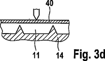
図3は、穿刺要素と検査領域を通る切り込みを示す4つの実施形態を示している。これは、対処されるべき技術的な問題を例証している。図3aでは、体液チャネルの隣の身体穿刺要素に皮下コーティング16を付加した実施形態を示す。図3aに見られるように、検査領域と皮膚穿刺要素との接触は、検査領域と体液を接触させるだけでなく、接触中に、一方で、検査領域(またはキャリア)間に毛管空間が、もう一方で、体液通路の隣に突出部が形成される。通常これによって、チャネル内に滞留しているサンプル流体を、検査領域上のみでなく、さらに、生成された小さい毛管空間内へも搬送する高い毛管引力が作り出される。疎水性コーティング16は、皮膚穿刺要素14の上方面とキャリアまたは検査領域との間にサンプル体液が滲出することを防止する。搬送されたサンプル体液の量が、検査領域を正確な測定を達成できる形で湿潤するのに十分となるように、サンプルを検査材料の専用範囲上へ搬送することが望ましい。サンプル体液を検査領域の他の領域、あるいはキャリアへ損失してしまうことは、専用領域内で検査材料が十分湿潤されず、測定を正確に実施できないことを意味する。
FIG. 3 shows four embodiments showing the piercing element and the cut through the examination area. This illustrates the technical problem to be addressed. In FIG. 3a, an embodiment is shown in which a
図3bは、サンプル体液の故意でない滲出を防止するさらなる実施形態を示す。図2と同様に、この実施形態は、検査領域またはキャリアと接触する直立チャネルを備えている。このために、空間内に滲入する体液が外部チャネル壁にて停止するため、サンプル体液の損失が大幅に低減される。しかし、チャネル壁は、図3bに示すように四角形である必要はなく、図3cまたは3dに示すように尖った形状であってもよい。 FIG. 3b shows a further embodiment that prevents unintentional exudation of sample body fluid. Similar to FIG. 2, this embodiment includes an upstanding channel in contact with the inspection region or carrier. For this reason, since the body fluid which permeates into the space stops at the external channel wall, the loss of the sample body fluid is greatly reduced. However, the channel walls need not be square as shown in FIG. 3b, but may be pointed as shown in FIG. 3c or 3d.
図4は、サンプル体液と検査領域との接触の電気トリガリングの概念を示す。 FIG. 4 shows the concept of electrical triggering of the contact between the sample body fluid and the examination area.
しかし、この一般的な概念を、チャネルを具備した支持構造の特別な実施形態として、皮膚穿刺要素に関連させて図4に示す。体液をトリガリングするためには、サンプル体液25とキャリア40の間に高電位を付加する。これにより、サンプル体液がチャネルから検査領域上へ移動するか、または、キャリアがチャネルの方向へ移動する。いずれの場合においても、電位を入れることにより、サンプル体液による検査領域の湿潤を非常に短い時間フレーム内で誘発することができる。キャリアの透過図に見られるように、検査領域を湿潤させるべく薄型の毛管チャネルよりも多量の体液を提供するために、検査領域の下のチャネルが収集領域26内へと続いている。
However, this general concept is illustrated in FIG. 4 in connection with a skin piercing element as a special embodiment of a support structure with channels. In order to trigger the body fluid, a high potential is applied between the
図4Bは、収集領域の好ましい実施形態をより詳細に示す。同図中に見られるように、収集領域26は、体液の検査領域上への移動を促進する直立要素26’を備えることが好ましい。これらの直立要素は、一方で、体液を搬送するために自体の側にて高い電荷を誘発し、もう一方で、収集領域26の毛管引力を向上させることで、体液による充填を改善する。
FIG. 4B shows the preferred embodiment of the collection area in more detail. As can be seen in the figure, the
図5A、図5B、図5Cは、相互に離間した皮膚穿刺要素および検査領域を提供するためのより単純な設計を示し、この設計により、起動時に、検査領域をチャネル内のサンプル体液と接触させることが可能になる。図5Aの実施形態は図1のものと類似している。皮膚穿刺要素は、毛管チャネル11が内設された要素内部13’と接続したフレームを備えている。内部とフレームは、屈曲可能な部分51によって接続している。毛管チャネルの充填後に、内部がフレームに対して捻れることにより、毛管の一部分がキャリア43の下の検査領域と接触する。屈曲可能な部分を曲げ回すことにより、内部が検査領域と或る角度にて接触する。これは、気泡が侵入することなく検査領域を均等に湿潤することができるため、特に有利であることが証明されている。
FIGS. 5A, 5B, and 5C show a simpler design for providing a skin piercing element and a test area that are spaced apart from each other, which brings the test area into contact with the sample body fluid in the channel upon activation. It becomes possible. The embodiment of FIG. 5A is similar to that of FIG. The skin piercing element comprises a frame connected to an element interior 13 'in which a
図5Bは、キャリア43とその支持部が、屈曲可能な部分51’を介して、毛管を備えた主要部分14’と接続される実施形態を示す。ここでも、毛管と検査領域の間の接触は傾斜した形で達成される。
FIG. 5B shows an embodiment in which the
図5Cは、2つの端部にてフレーム14”と接続した内部13”を備える実施形態を示す。内部13”の中心部分に圧力が下側から付加されると、この中心部分がキャリア43の下の検査領域に対して屈曲する。この内部を再度曲げることにより、角度付けされた接触が達成される。
FIG. 5C shows an embodiment with an interior 13 ″ connected to a
図6は、毛管チャネルの向上した形状を概略的に示す。チャネル内における体液の充填レベルは、毛管の幅が減少するにしたがって増加する。図6の毛管は、皮膚穿刺要素の先端部分へ続く第1領域aを備えている。増大した直径を有する第2領域bは、より多量のサンプル容量を提供するためのものである。特に有用なのは、幅を減少させた第3領域cである。減少した幅のために充填レベルが増加し、これにより、チャネルから検査領域への体液の搬送の成功率が高まる。したがって、検査領域がまず領域cと接触し、次に領域bと接触できるように、検査領域と毛管を傾斜した形で接触させることが好ましい。これにより、体液搬送が領域cによって安全に開始され、領域bによって十分な量のサンプルが提供される。領域cの下流に領域dを採用して、汚染されたサンプル体液または間質液を排出するようにしてもよい。 FIG. 6 schematically shows the improved shape of the capillary channel. The level of fluid filling in the channel increases as the capillary width decreases. The capillary of FIG. 6 includes a first region a that continues to the distal end portion of the skin piercing element. The second region b having an increased diameter is for providing a larger sample volume. Particularly useful is the third region c with a reduced width. The filling level increases due to the reduced width, which increases the success rate of the transfer of body fluid from the channel to the examination area. Therefore, it is preferable to bring the inspection region and the capillary into contact with each other so that the inspection region can first contact the region c and then contact the region b. Thereby, body fluid conveyance is safely started by the area c, and a sufficient amount of sample is provided by the area b. A region d may be employed downstream of the region c to discharge the contaminated sample body fluid or interstitial fluid.
図7は、先端領域内へ続く第1領域aと、増大した直径を有する第2領域bとを備えた皮膚穿刺要素を示す。図Aは、皮膚が穿刺され、血液が毛管チャネルの領域a内に採取された後の状態を示す。より減少した領域bの毛管引力のために、サンプル体液は領域aを充填するが、領域bは充填しない。皮膚穿刺要素がキャリア43と接触せしめられると、或る部分における開放チャネル構造a、b、dがその先端にて閉鎖され、これにより、この部分における毛管引力が増加することで、収集領域bが充填され、キャリア43の下側上の検査領域がサンプル体液と接触する。光学要素の形状を目的として、円形の検出範囲を設けることが有利である。
FIG. 7 shows a skin piercing element with a first region a that continues into the tip region and a second region b that has an increased diameter. FIG. A shows the state after the skin has been punctured and blood has been collected in region a of the capillary channel. Due to the reduced capillary attraction of region b, the sample body fluid fills region a, but does not fill region b. When the skin piercing element is brought into contact with the
図7による皮膚穿刺要素は以下の方法にて使用することができる。 The skin piercing element according to FIG. 7 can be used in the following manner.
皮膚を穿刺し、
体液を、毛管チャネルの一部分(領域a)内にサンプリングし、
収集領域b内の毛管チャネルを検査領域および/またはキャリアと接触させて、領域bが体液で充填されるようにし、
体液からの検体との反応による検査領域の変化を検出する。
Puncture the skin,
Sampling bodily fluid into a portion of the capillary channel (region a);
Bringing the capillary channel in the collection region b into contact with the examination region and / or carrier so that the region b is filled with bodily fluids;
Changes in the examination region due to the reaction with the specimen from the body fluid are detected.
図8A、図8Bは、複数(図示の場合では3つ)の検査領域にサンプル体液を提供するよう適合された皮膚穿刺要素10の実施形態を示す。両図中の体液通路11は、鋭利な先端15付近の前端領域から開始している。図8A、図8Bをさらに説明するために、図1を参照する。図8A、図8Bは、関連する検査領域と接触するとこれらを湿潤させるためのサンプルを保持するよう機能するプーリング(pooling)領域47、47’、47”を設けている。プーリング領域は、より多量の体液を貯められるように、毛管チャネル11よりも大きな直径を有することが好ましい。図8Aでは、プーリング領域は、真直ぐな体液通路11内に一体に形成されており、一方、図8Bでは、体液をプーリング領域内へ案内するための、主要体液通路から分岐した側部チャネルが設けられている。そのため、本発明のサンプリング要素は、主要体液通路から分岐した側部流体チャネルと、これらの側部体液チャネル内に設けられたプーリング領域とを備えることができる。これにより、プーリング領域と、さらに検査領域との接触場所とを空間的に離間させ、接触場所間における干渉を防止することができる。
8A and 8B show an embodiment of a
Claims (11)
前記サンプル体液の前記体液通路への充填中に前記体液通路によって体液接触されない体液受容手段をさらに備え、これにより、初期段階において、前記通路内の体液が体液受容手段と接触せず、
前記体液受容手段が2または3以上の検査領域を備え、
検査領域を連続的に読み取るべく前記体液受容手段および光学装置を相互に移動させて検査領域が連続的に読み取られ評価されてなる
ことを特徴とする検査装置。A sampling element having a body fluid passage for receiving a sample body fluid, wherein at least a portion of the body fluid passage is open to the surrounding environment;
Further comprising a bodily fluid receiving means that is not in contact with the bodily fluid passage by the bodily fluid passage during filling of the bodily fluid passage with the sample bodily fluid ;
The body fluid receiving means comprises two or three or more examination areas;
An inspection apparatus, wherein the body fluid receiving means and the optical device are moved relative to each other in order to continuously read the inspection area, and the inspection area is continuously read and evaluated.
前記サンプル体液の前記体液通路への充填中に前記体液通路から流体接触されない体液受容手段をさらに備え、これにより、初期段階において、前記通路内の体液が前記体液受容手段と接触することがなく、
前記体液受容手段が2つまたはそれ以上の検査領域を備え、
検査領域を連続的に読み取るべく前記体液受容手段および光学装置を相互に移動させて検査領域が連続的に読み取られ評価されてなる体液分析のためのシステム。Comprising a sampling element provided with a body fluid passage for receiving body fluid, at least a part of said body fluid passage being open to the surrounding environment;
It further comprises a body fluid receiving means that is not in fluid contact from the body fluid passage during filling of the sample body fluid into the body fluid passage .
The body fluid receiving means comprises two or more examination areas;
A system for analyzing body fluid, wherein the body fluid receiving means and the optical device are moved relative to each other to continuously read the examination area, and the examination area is continuously read and evaluated.
体液受容手段をさらに備え、
前記体液受容手段が、第1状態においてチャネルから離間し、第2状態にある接触領域内の体液によって接触されているため、排出領域からの体液によって接触されることがなく、
前記体液受容手段が2つまたはそれ以上の検査領域を備えてなる分析装置。It has a support structure having a channel that can be contacted from the surroundings at least in the access region, and the channel has a body fluid introduction region, and further a body fluid discharge region located downstream of the contact region,
Further comprising a body fluid receiving means,
Since the body fluid receiving means is separated from the channel in the first state and is contacted by the body fluid in the contact region in the second state, it is not contacted by the body fluid from the discharge region,
An analyzer in which the body fluid receiving means comprises two or more examination areas.
チャネルから離間している体液受容手段をさらに備え、
オン状態において、前記接触領域内の体液と前記体液受容手段との間に電位を付加する電位ソースをさらに備え、これにより、前記接触領域からの体液が前記体液受容手段上へ搬送され、
前記体液受容手段が2または3以上の検査領域を備え、
検査領域を連続的に読み取るべく前記体液受容手段および光学装置を相互に移動させて検査領域が連続的に読み取られ評価されてなる分析装置。A support structure having a channel for receiving a bodily fluid in an interior accessible at least in the contact area from the surroundings;
Further comprising a body fluid receiving means spaced from the channel;
In the on state, further comprising a potential source for applying a potential between the bodily fluid in the contact area and the bodily fluid receiving means, whereby the bodily fluid from the contact area is conveyed onto the bodily fluid receiving means,
The body fluid receiving means comprises two or three or more examination areas;
An analysis apparatus in which the body fluid receiving means and the optical device are moved relative to each other so that the inspection area is continuously read, and the inspection area is continuously read and evaluated.
Applications Claiming Priority (3)
| Application Number | Priority Date | Filing Date | Title |
|---|---|---|---|
| EP04005385 | 2004-03-06 | ||
| EP04005385.2 | 2004-03-06 | ||
| PCT/EP2005/002316 WO2005084545A1 (en) | 2004-03-06 | 2005-03-04 | Body fluid sampling device |
Publications (3)
| Publication Number | Publication Date |
|---|---|
| JP2007527288A JP2007527288A (en) | 2007-09-27 |
| JP2007527288A5 JP2007527288A5 (en) | 2010-06-24 |
| JP4602398B2 true JP4602398B2 (en) | 2010-12-22 |
Family
ID=34917165
Family Applications (3)
| Application Number | Title | Priority Date | Filing Date |
|---|---|---|---|
| JP2007501224A Expired - Fee Related JP4917013B2 (en) | 2004-03-06 | 2005-03-04 | Body fluid collection device |
| JP2007501232A Expired - Fee Related JP4602398B2 (en) | 2004-03-06 | 2005-03-04 | Body fluid sampling device |
| JP2007501237A Expired - Fee Related JP4959545B2 (en) | 2004-03-06 | 2005-03-07 | Body fluid sampling device and body fluid analysis system |
Family Applications Before (1)
| Application Number | Title | Priority Date | Filing Date |
|---|---|---|---|
| JP2007501224A Expired - Fee Related JP4917013B2 (en) | 2004-03-06 | 2005-03-04 | Body fluid collection device |
Family Applications After (1)
| Application Number | Title | Priority Date | Filing Date |
|---|---|---|---|
| JP2007501237A Expired - Fee Related JP4959545B2 (en) | 2004-03-06 | 2005-03-07 | Body fluid sampling device and body fluid analysis system |
Country Status (16)
| Country | Link |
|---|---|
| US (4) | US8000762B2 (en) |
| EP (5) | EP1722670B1 (en) |
| JP (3) | JP4917013B2 (en) |
| KR (1) | KR101198054B1 (en) |
| CN (5) | CN1929784B (en) |
| AU (2) | AU2005220022B2 (en) |
| BR (2) | BRPI0508528B8 (en) |
| CA (5) | CA2558086C (en) |
| DK (1) | DK1722670T3 (en) |
| ES (4) | ES2541680T3 (en) |
| HK (3) | HK1104439A1 (en) |
| HU (1) | HUE025706T2 (en) |
| PL (4) | PL1725168T3 (en) |
| PT (3) | PT1722670E (en) |
| SG (1) | SG153808A1 (en) |
| WO (3) | WO2005084530A2 (en) |
Families Citing this family (145)
| Publication number | Priority date | Publication date | Assignee | Title |
|---|---|---|---|---|
| US6391005B1 (en) | 1998-03-30 | 2002-05-21 | Agilent Technologies, Inc. | Apparatus and method for penetration with shaft having a sensor for sensing penetration depth |
| US8641644B2 (en) | 2000-11-21 | 2014-02-04 | Sanofi-Aventis Deutschland Gmbh | Blood testing apparatus having a rotatable cartridge with multiple lancing elements and testing means |
| US9427532B2 (en) | 2001-06-12 | 2016-08-30 | Sanofi-Aventis Deutschland Gmbh | Tissue penetration device |
| US7025774B2 (en) | 2001-06-12 | 2006-04-11 | Pelikan Technologies, Inc. | Tissue penetration device |
| US7981056B2 (en) | 2002-04-19 | 2011-07-19 | Pelikan Technologies, Inc. | Methods and apparatus for lancet actuation |
| US8337419B2 (en) | 2002-04-19 | 2012-12-25 | Sanofi-Aventis Deutschland Gmbh | Tissue penetration device |
| US9795747B2 (en) | 2010-06-02 | 2017-10-24 | Sanofi-Aventis Deutschland Gmbh | Methods and apparatus for lancet actuation |
| US7749174B2 (en) | 2001-06-12 | 2010-07-06 | Pelikan Technologies, Inc. | Method and apparatus for lancet launching device intergrated onto a blood-sampling cartridge |
| US9226699B2 (en) | 2002-04-19 | 2016-01-05 | Sanofi-Aventis Deutschland Gmbh | Body fluid sampling module with a continuous compression tissue interface surface |
| ATE485766T1 (en) | 2001-06-12 | 2010-11-15 | Pelikan Technologies Inc | ELECTRICAL ACTUATING ELEMENT FOR A LANCET |
| DE60234598D1 (en) | 2001-06-12 | 2010-01-14 | Pelikan Technologies Inc | SELF-OPTIMIZING LANZET DEVICE WITH ADAPTANT FOR TEMPORAL FLUCTUATIONS OF SKIN PROPERTIES |
| US7004928B2 (en) | 2002-02-08 | 2006-02-28 | Rosedale Medical, Inc. | Autonomous, ambulatory analyte monitor or drug delivery device |
| US7909778B2 (en) | 2002-04-19 | 2011-03-22 | Pelikan Technologies, Inc. | Method and apparatus for penetrating tissue |
| US7547287B2 (en) | 2002-04-19 | 2009-06-16 | Pelikan Technologies, Inc. | Method and apparatus for penetrating tissue |
| US8579831B2 (en) | 2002-04-19 | 2013-11-12 | Sanofi-Aventis Deutschland Gmbh | Method and apparatus for penetrating tissue |
| US7232451B2 (en) | 2002-04-19 | 2007-06-19 | Pelikan Technologies, Inc. | Method and apparatus for penetrating tissue |
| US9248267B2 (en) | 2002-04-19 | 2016-02-02 | Sanofi-Aventis Deustchland Gmbh | Tissue penetration device |
| US7674232B2 (en) | 2002-04-19 | 2010-03-09 | Pelikan Technologies, Inc. | Method and apparatus for penetrating tissue |
| US7229458B2 (en) | 2002-04-19 | 2007-06-12 | Pelikan Technologies, Inc. | Method and apparatus for penetrating tissue |
| US7226461B2 (en) | 2002-04-19 | 2007-06-05 | Pelikan Technologies, Inc. | Method and apparatus for a multi-use body fluid sampling device with sterility barrier release |
| US7491178B2 (en) | 2002-04-19 | 2009-02-17 | Pelikan Technologies, Inc. | Method and apparatus for penetrating tissue |
| US7892183B2 (en) | 2002-04-19 | 2011-02-22 | Pelikan Technologies, Inc. | Method and apparatus for body fluid sampling and analyte sensing |
| US7331931B2 (en) | 2002-04-19 | 2008-02-19 | Pelikan Technologies, Inc. | Method and apparatus for penetrating tissue |
| US7297122B2 (en) | 2002-04-19 | 2007-11-20 | Pelikan Technologies, Inc. | Method and apparatus for penetrating tissue |
| US8267870B2 (en) | 2002-04-19 | 2012-09-18 | Sanofi-Aventis Deutschland Gmbh | Method and apparatus for body fluid sampling with hybrid actuation |
| US7901362B2 (en) | 2002-04-19 | 2011-03-08 | Pelikan Technologies, Inc. | Method and apparatus for penetrating tissue |
| US9795334B2 (en) | 2002-04-19 | 2017-10-24 | Sanofi-Aventis Deutschland Gmbh | Method and apparatus for penetrating tissue |
| US8702624B2 (en) | 2006-09-29 | 2014-04-22 | Sanofi-Aventis Deutschland Gmbh | Analyte measurement device with a single shot actuator |
| US7976476B2 (en) | 2002-04-19 | 2011-07-12 | Pelikan Technologies, Inc. | Device and method for variable speed lancet |
| US8784335B2 (en) | 2002-04-19 | 2014-07-22 | Sanofi-Aventis Deutschland Gmbh | Body fluid sampling device with a capacitive sensor |
| US8360992B2 (en) | 2002-04-19 | 2013-01-29 | Sanofi-Aventis Deutschland Gmbh | Method and apparatus for penetrating tissue |
| US7892185B2 (en) | 2002-04-19 | 2011-02-22 | Pelikan Technologies, Inc. | Method and apparatus for body fluid sampling and analyte sensing |
| US8221334B2 (en) | 2002-04-19 | 2012-07-17 | Sanofi-Aventis Deutschland Gmbh | Method and apparatus for penetrating tissue |
| US9314194B2 (en) | 2002-04-19 | 2016-04-19 | Sanofi-Aventis Deutschland Gmbh | Tissue penetration device |
| US7175642B2 (en) | 2002-04-19 | 2007-02-13 | Pelikan Technologies, Inc. | Methods and apparatus for lancet actuation |
| US7815579B2 (en) | 2005-03-02 | 2010-10-19 | Roche Diagnostics Operations, Inc. | Dynamic integrated lancing test strip with sterility cover |
| US7214200B2 (en) | 2002-12-30 | 2007-05-08 | Roche Diagnostics Operations, Inc. | Integrated analytical test element |
| US7211052B2 (en) | 2002-12-30 | 2007-05-01 | Roche Diagnostics Operations, Inc. | Flexible test strip lancet device |
| US8574895B2 (en) | 2002-12-30 | 2013-11-05 | Sanofi-Aventis Deutschland Gmbh | Method and apparatus using optical techniques to measure analyte levels |
| US7052652B2 (en) | 2003-03-24 | 2006-05-30 | Rosedale Medical, Inc. | Analyte concentration detection devices and methods |
| EP1628567B1 (en) | 2003-05-30 | 2010-08-04 | Pelikan Technologies Inc. | Method and apparatus for fluid injection |
| DK1633235T3 (en) | 2003-06-06 | 2014-08-18 | Sanofi Aventis Deutschland | Apparatus for sampling body fluid and detecting analyte |
| WO2006001797A1 (en) | 2004-06-14 | 2006-01-05 | Pelikan Technologies, Inc. | Low pain penetrating |
| US7920906B2 (en) | 2005-03-10 | 2011-04-05 | Dexcom, Inc. | System and methods for processing analyte sensor data for sensor calibration |
| US8282576B2 (en) | 2003-09-29 | 2012-10-09 | Sanofi-Aventis Deutschland Gmbh | Method and apparatus for an improved sample capture device |
| EP1680014A4 (en) | 2003-10-14 | 2009-01-21 | Pelikan Technologies Inc | Method and apparatus for a variable user interface |
| US9247900B2 (en) | 2004-07-13 | 2016-02-02 | Dexcom, Inc. | Analyte sensor |
| US7822454B1 (en) | 2005-01-03 | 2010-10-26 | Pelikan Technologies, Inc. | Fluid sampling device with improved analyte detecting member configuration |
| EP1706026B1 (en) | 2003-12-31 | 2017-03-01 | Sanofi-Aventis Deutschland GmbH | Method and apparatus for improving fluidic flow and sample capture |
| PL1725168T3 (en) | 2004-03-06 | 2016-10-31 | Body fluid sampling device | |
| US7819822B2 (en) | 2004-03-06 | 2010-10-26 | Roche Diagnostics Operations, Inc. | Body fluid sampling device |
| US8828203B2 (en) | 2004-05-20 | 2014-09-09 | Sanofi-Aventis Deutschland Gmbh | Printable hydrogels for biosensors |
| EP1765194A4 (en) | 2004-06-03 | 2010-09-29 | Pelikan Technologies Inc | Method and apparatus for a fluid sampling device |
| US9775553B2 (en) | 2004-06-03 | 2017-10-03 | Sanofi-Aventis Deutschland Gmbh | Method and apparatus for a fluid sampling device |
| WO2006127694A2 (en) | 2004-07-13 | 2006-11-30 | Dexcom, Inc. | Analyte sensor |
| US7946984B2 (en) | 2004-07-13 | 2011-05-24 | Dexcom, Inc. | Transcutaneous analyte sensor |
| US7488298B2 (en) * | 2004-10-08 | 2009-02-10 | Roche Diagnostics Operations, Inc. | Integrated lancing test strip with capillary transfer sheet |
| EP1654985A1 (en) * | 2004-11-09 | 2006-05-10 | F. Hoffmann-La Roche Ag | Sampling device for sample liquid |
| US8652831B2 (en) * | 2004-12-30 | 2014-02-18 | Sanofi-Aventis Deutschland Gmbh | Method and apparatus for analyte measurement test time |
| EP1835848A4 (en) * | 2004-12-30 | 2009-07-29 | Pelikan Technologies Inc | Method and apparatus for analyte measurement test time |
| US20060281187A1 (en) | 2005-06-13 | 2006-12-14 | Rosedale Medical, Inc. | Analyte detection devices and methods with hematocrit/volume correction and feedback control |
| EP1759633A1 (en) | 2005-09-01 | 2007-03-07 | F.Hoffmann-La Roche Ag | Device for sampling bodily fluids and its fabrication method |
| EP1928304B1 (en) | 2005-09-30 | 2012-10-24 | Intuity Medical, Inc. | Catalysts for body fluid sample extraction |
| US8801631B2 (en) | 2005-09-30 | 2014-08-12 | Intuity Medical, Inc. | Devices and methods for facilitating fluid transport |
| CN101287406B (en) | 2005-10-15 | 2013-04-10 | 霍夫曼-拉罗奇有限公司 | Test element and test system for examining a body fluid |
| US20090093735A1 (en) * | 2006-03-29 | 2009-04-09 | Stephan Korner | Test unit and test system for analyzing body fluids |
| EP1839576A1 (en) | 2006-03-29 | 2007-10-03 | F.Hoffmann-La Roche Ag | Test system with test unit for analysing body fluids |
| EP1878387B1 (en) | 2006-07-15 | 2010-11-24 | Roche Diagnostics GmbH | Lancet, lancet feeder belt and pricking device for creating a puncture wound |
| EP1878386A1 (en) * | 2006-07-15 | 2008-01-16 | Roche Diagnostics GmbH | Process to produce lancet; lancet, lancet band and device for pricking the skin |
| EP1880671B1 (en) * | 2006-07-18 | 2010-09-08 | Roche Diagnostics GmbH | Lancet wheel |
| EP1894526A1 (en) * | 2006-09-04 | 2008-03-05 | F. Hoffmann-la Roche AG | Lancet |
| US8852124B2 (en) * | 2006-10-13 | 2014-10-07 | Roche Diagnostics Operations, Inc. | Tape transport lance sampler |
| ATE430514T1 (en) | 2006-10-14 | 2009-05-15 | Hoffmann La Roche | LANCET WITH CAPILLARY CHANNEL |
| EP1977686A1 (en) * | 2007-04-04 | 2008-10-08 | F.Hoffmann-La Roche Ag | Disposable diagnostic article |
| MX340230B (en) | 2007-04-30 | 2016-07-01 | F Hoffmann-La Roche Ag * | Instrument and system for producing a sample of a body liquid and for analysis thereof. |
| US20110092854A1 (en) | 2009-10-20 | 2011-04-21 | Uwe Kraemer | Instruments and system for producing a sample of a body fluid and for analysis thereof |
| ES2687620T3 (en) | 2007-05-04 | 2018-10-26 | Opko Diagnostics, Llc | Device and method for analysis in microfluidic systems |
| EP2150177B1 (en) | 2007-05-29 | 2018-04-25 | Roche Diabetes Care GmbH | Test system for measuring the concentration of an analyte in a body fluid |
| EP2025287A1 (en) * | 2007-08-16 | 2009-02-18 | F.Hoffmann-La Roche Ag | Diagnostic disposable part and method for its production |
| ATE534329T1 (en) * | 2007-09-17 | 2011-12-15 | Hoffmann La Roche | DISPOSABLE DEVICE FOR ANALYZING BODY FLUID |
| EP2205153B1 (en) * | 2007-10-08 | 2017-04-19 | Roche Diabetes Care GmbH | Analysis system for automatic skin prick analysis |
| ATE488179T1 (en) * | 2007-10-12 | 2010-12-15 | Hoffmann La Roche | TEST BAND DEVICE FOR EXAMINING BODY FLUID |
| KR101009447B1 (en) | 2007-11-12 | 2011-01-19 | 바디텍메드 주식회사 | Device for sampling and preprocessing biological fluids and method thereof |
| US7766846B2 (en) * | 2008-01-28 | 2010-08-03 | Roche Diagnostics Operations, Inc. | Rapid blood expression and sampling |
| AU2013202929B2 (en) * | 2008-01-28 | 2016-05-26 | F. Hoffmann-La Roche Ag | System for detection of an analyte in a body fluid |
| EP2087840A1 (en) | 2008-02-11 | 2009-08-12 | F.Hoffmann-La Roche Ag | Device and method for removing bodily fluids |
| EP2093284A1 (en) | 2008-02-19 | 2009-08-26 | F.Hoffmann-La Roche Ag | Stabilisation of dehydrogenases with stable coenzymes |
| WO2009105709A1 (en) | 2008-02-21 | 2009-08-27 | Dexcom, Inc. | Systems and methods for processing, transmitting and displaying sensor data |
| EP3616618B1 (en) * | 2008-03-05 | 2022-11-30 | Becton, Dickinson and Company | Capillary action collection device |
| WO2009126900A1 (en) | 2008-04-11 | 2009-10-15 | Pelikan Technologies, Inc. | Method and apparatus for analyte detecting device |
| WO2009145920A1 (en) | 2008-05-30 | 2009-12-03 | Intuity Medical, Inc. | Body fluid sampling device -- sampling site interface |
| EP2299904B1 (en) | 2008-06-06 | 2019-09-11 | Intuity Medical, Inc. | Medical measurement method |
| US9636051B2 (en) | 2008-06-06 | 2017-05-02 | Intuity Medical, Inc. | Detection meter and mode of operation |
| EP2316339A4 (en) * | 2008-08-01 | 2012-10-24 | Lightnix Inc | Sensor with fine needle having channel formed therein |
| US8118824B2 (en) * | 2008-09-16 | 2012-02-21 | Roche Diagnostics Operations, Inc. | Magnetic powered lancing drive |
| EP2181651A1 (en) * | 2008-10-29 | 2010-05-05 | Roche Diagnostics GmbH | Instrument and system for producing a sample of a body liquid and for analysis thereof |
| KR20130020807A (en) * | 2008-11-07 | 2013-02-28 | 에프. 호프만-라 로슈 아게 | Fine-grained filler substances for photometric reaction films |
| EP2208459A1 (en) * | 2009-01-16 | 2010-07-21 | F. Hoffmann-Roche AG | System and method for analysing a body fluid |
| US9375169B2 (en) | 2009-01-30 | 2016-06-28 | Sanofi-Aventis Deutschland Gmbh | Cam drive for managing disposable penetrating member actions with a single motor and motor and control system |
| WO2010087999A1 (en) | 2009-02-02 | 2010-08-05 | Claros Diagnostics, Inc. | Structures for controlling light interaction with microfluidic devices |
| EP2218400A1 (en) | 2009-02-12 | 2010-08-18 | Roche Diagnostics GmbH | Lance with test area |
| EP2398909B1 (en) | 2009-02-19 | 2015-07-22 | F. Hoffmann-La Roche AG | Fast reaction kinetics of enzymes having low activity in dry chemistry layers |
| KR20130127555A (en) | 2009-02-19 | 2013-11-22 | 에프. 호프만-라 로슈 아게 | Fast reaction kinetics of enzymes having low activity in dry chemistry layers |
| EP2241252A1 (en) * | 2009-03-17 | 2010-10-20 | F. Hoffmann-La Roche AG | Testing device, in particular for blood sugar tests |
| CN102369431B (en) * | 2009-04-07 | 2014-04-09 | 松下电器产业株式会社 | Sensor chip, measuring instrument using same, and blood test device |
| EP2263526A1 (en) | 2009-06-19 | 2010-12-22 | Roche Diagnostics GmbH | Piercing system |
| EP2272429A1 (en) * | 2009-07-10 | 2011-01-12 | Roche Diagnostics GmbH | Lancet |
| EP2283774A1 (en) | 2009-08-13 | 2011-02-16 | Roche Diagnostics GmbH | Test element for analysing a body fluid |
| EP2287605A1 (en) | 2009-08-20 | 2011-02-23 | Roche Diagnostics GmbH | Simplified magazining of integrated systems |
| EP2322924A1 (en) | 2009-10-15 | 2011-05-18 | F. Hoffmann-La Roche AG | Protection from hydrophobic agents |
| WO2011048200A2 (en) | 2009-10-22 | 2011-04-28 | Roche Diagnostics Gmbh | Micro-capillary system having increased sample volume |
| CN102068262B (en) * | 2009-11-23 | 2012-11-21 | 财团法人金属工业研究发展中心 | Sampling apparatus with flexible pressing zone |
| EP3106871B1 (en) | 2009-11-30 | 2021-10-27 | Intuity Medical, Inc. | A method of verifying the accuracy of the operation of an analyte monitoring device |
| EP2333544A1 (en) | 2009-12-11 | 2011-06-15 | F. Hoffmann-La Roche AG | Sterilisable chemistry for test elements |
| KR101506928B1 (en) | 2009-12-16 | 2015-03-30 | 에프. 호프만-라 로슈 아게 | Detecting the decomposition of enzymes in a test element by means of controlled release of protected analyte |
| US8965476B2 (en) | 2010-04-16 | 2015-02-24 | Sanofi-Aventis Deutschland Gmbh | Tissue penetration device |
| EP2382921A1 (en) | 2010-04-30 | 2011-11-02 | Roche Diagnostics GmbH | Lancing device with automatic disengagement |
| CA2803797A1 (en) | 2010-06-25 | 2011-12-29 | Intuity Medical, Inc. | Analyte monitoring methods and systems |
| EP2417910B1 (en) * | 2010-08-11 | 2013-06-26 | Roche Diagnostics GmbH | Analytical test unit and test system |
| TWI532530B (en) * | 2010-10-29 | 2016-05-11 | 萬國商業機器公司 | Multilayer microfluidic probe head with immersion channels and fabrication thereof |
| TWI532468B (en) * | 2011-03-22 | 2016-05-11 | 福 赫夫曼 拉瑞奇股份有限公司 | Analytical aid with hydrophilic coating containing nanoparticles with silica structure |
| EP2520225B1 (en) * | 2011-05-06 | 2014-05-21 | Roche Diagnostics GmbH | Lancet |
| EP3407064B1 (en) | 2011-08-03 | 2020-04-22 | Intuity Medical, Inc. | Body fluid sampling arrangement |
| KR101651809B1 (en) * | 2011-09-23 | 2016-08-29 | 에프. 호프만-라 로슈 아게 | Method for the mask-etching of a piercing element |
| CN104364788B (en) | 2012-03-05 | 2018-02-06 | 阿克蒂克合伙公司 | Predict prostate cancer risk and the device of prostate gland volume |
| AU2013293078B2 (en) | 2012-07-23 | 2017-09-07 | Tasso, Inc. | Methods, systems, and devices relating to open microfluidic channels |
| EP3375425B1 (en) * | 2012-09-06 | 2022-03-09 | Labrador Diagnostics LLC | Sample collection device |
| US20150320348A1 (en) * | 2012-11-16 | 2015-11-12 | Lightstat, Llc | Disposable sample collection method and apparatus |
| EP2777499B1 (en) * | 2013-03-15 | 2015-09-16 | Ortho-Clinical Diagnostics Inc | Rotatable fluid sample collection device |
| US9523653B2 (en) | 2013-05-09 | 2016-12-20 | Changsha Sinocare Inc. | Disposable test sensor with improved sampling entrance |
| US10729386B2 (en) | 2013-06-21 | 2020-08-04 | Intuity Medical, Inc. | Analyte monitoring system with audible feedback |
| US9518951B2 (en) | 2013-12-06 | 2016-12-13 | Changsha Sinocare Inc. | Disposable test sensor with improved sampling entrance |
| US9897566B2 (en) | 2014-01-13 | 2018-02-20 | Changsha Sinocare Inc. | Disposable test sensor |
| TWI548395B (en) | 2014-01-28 | 2016-09-11 | 微凸科技股份有限公司 | Transdermal micrneedles continuous monitoring system |
| US9939401B2 (en) | 2014-02-20 | 2018-04-10 | Changsha Sinocare Inc. | Test sensor with multiple sampling routes |
| US10779757B2 (en) * | 2014-08-01 | 2020-09-22 | Tasso, Inc. | Devices, systems and methods for gravity-enhanced microfluidic collection, handling and transferring of fluids |
| EP3174463B1 (en) | 2014-08-01 | 2020-07-29 | Tasso, Inc. | Systems for gravity-enhanced microfluidic collection, handling and transferring of fluids |
| CN104874098B (en) * | 2015-04-08 | 2018-04-10 | 上海交通大学 | A kind of hollow metal micropin and its batch preparation |
| CN105738462A (en) * | 2016-02-24 | 2016-07-06 | 长沙金域医学检验所有限公司 | Detection method for microelements in peripheral blood |
| EP3451928B1 (en) * | 2016-05-04 | 2020-04-15 | midge medical GmbH | Body fluid extraction device |
| CN106137223B (en) * | 2016-08-12 | 2019-04-26 | 上海移宇科技股份有限公司 | The fully integrated bodily fluid sampling analyzer of single step |
| US10596591B2 (en) * | 2017-01-04 | 2020-03-24 | Red Devil Inc. | Material dispensing system and method |
| USD967402S1 (en) * | 2019-06-05 | 2022-10-18 | Aidian Oy | Blood collecting device |
| CN117783242A (en) * | 2019-08-20 | 2024-03-29 | 深圳硅基传感科技有限公司 | Working electrode of glucose sensor suitable for mass production |
| CN111956237B (en) * | 2020-07-31 | 2023-03-24 | 江苏麦酷博信息科技有限公司 | RFID blood collection card |
Family Cites Families (97)
| Publication number | Priority date | Publication date | Assignee | Title |
|---|---|---|---|---|
| US6268A (en) * | 1849-04-03 | James h | ||
| US2728343A (en) | 1954-06-03 | 1955-12-27 | S & R J Everett & Co Ltd | Sewing needles |
| SE388280B (en) | 1972-04-28 | 1976-09-27 | Harco Electr Ltd | APPLIANCE FOR QUANTITY SATURATION OF FLUID IN PROVREMSOR |
| US4218421A (en) | 1978-08-18 | 1980-08-19 | Honeywell Inc. | Disposable container for a continuous band of test strips |
| US4627445A (en) | 1985-04-08 | 1986-12-09 | Garid, Inc. | Glucose medical monitoring system |
| US4935346A (en) * | 1986-08-13 | 1990-06-19 | Lifescan, Inc. | Minimum procedure system for the determination of analytes |
| US5077010A (en) | 1987-07-15 | 1991-12-31 | Fuji Photo Film Co., Ltd. | Long-test-film cassette for biochemical analysis, and system for loading the same |
| USRE36268E (en) | 1988-03-15 | 1999-08-17 | Boehringer Mannheim Corporation | Method and apparatus for amperometric diagnostic analysis |
| US4995402A (en) * | 1988-10-12 | 1991-02-26 | Thorne, Smith, Astill Technologies, Inc. | Medical droplet whole blood and like monitoring |
| JPH0810207B2 (en) * | 1989-11-08 | 1996-01-31 | 日本特殊陶業株式会社 | Biosensor |
| US5172701A (en) | 1990-02-28 | 1992-12-22 | Medical Device Technologies, Inc. | Single use automated soft tissue aspiration biopsy device |
| US5055203A (en) * | 1990-05-22 | 1991-10-08 | Eastman Kodak Company | Blood collection device with reduced serum dispensing volume and integral needle |
| US5163442A (en) * | 1991-07-30 | 1992-11-17 | Harry Ono | Finger tip blood collector |
| DE4212315A1 (en) | 1992-04-13 | 1993-10-14 | Boehringer Mannheim Gmbh | Blood lancet device for drawing blood for diagnostic purposes |
| US5318514A (en) * | 1992-08-17 | 1994-06-07 | Btx, Inc. | Applicator for the electroporation of drugs and genes into surface cells |
| US5582184A (en) | 1993-10-13 | 1996-12-10 | Integ Incorporated | Interstitial fluid collection and constituent measurement |
| US5762770A (en) | 1994-02-21 | 1998-06-09 | Boehringer Mannheim Corporation | Electrochemical biosensor test strip |
| US5591139A (en) * | 1994-06-06 | 1997-01-07 | The Regents Of The University Of California | IC-processed microneedles |
| US5644177A (en) * | 1995-02-23 | 1997-07-01 | Wisconsin Alumni Research Foundation | Micromechanical magnetically actuated devices |
| AU731250B2 (en) * | 1995-11-13 | 2001-03-29 | Cortecs (Uk) Limited | Diagnostic test apparatus |
| CN1207056A (en) * | 1995-11-13 | 1999-02-03 | 科特克斯(英国)有限公司 | Diagnostic test apparatus |
| US5801057A (en) * | 1996-03-22 | 1998-09-01 | Smart; Wilson H. | Microsampling device and method of construction |
| AU3070397A (en) | 1996-05-17 | 1997-12-05 | Mercury Diagnostics Inc. | Methods and apparatus for sampling body fluid |
| DE69722414T2 (en) | 1996-07-03 | 2004-05-19 | Altea Therapeutics Corp. | MULTIPLE MECHANICAL MICROPERFORATION OF SKIN OR MUCOSA |
| US6486947B2 (en) * | 1998-07-22 | 2002-11-26 | Ljl Biosystems, Inc. | Devices and methods for sample analysis |
| US5931794A (en) | 1997-10-21 | 1999-08-03 | Pitesky; Isadore | Allergy testing apparatus |
| DE19824036A1 (en) * | 1997-11-28 | 1999-06-02 | Roche Diagnostics Gmbh | Analytical measuring device with lancing device |
| US6063040A (en) * | 1998-01-16 | 2000-05-16 | Specialized Health Products, Inc. | Self retracting needle apparatus and method for phlebotomy |
| SG102538A1 (en) * | 1998-04-24 | 2004-03-26 | Roche Diagnostics Gmbh | Storage container for analytical devices |
| US6214030B1 (en) | 1998-08-10 | 2001-04-10 | Mani, Inc. | Suture needle |
| US6132449A (en) * | 1999-03-08 | 2000-10-17 | Agilent Technologies, Inc. | Extraction and transportation of blood for analysis |
| US6660018B2 (en) * | 1999-03-08 | 2003-12-09 | Agilent Technologies, Inc. | Multiple lancet device |
| US6368563B1 (en) | 1999-03-12 | 2002-04-09 | Integ, Inc. | Collection well for body fluid tester |
| US6252195B1 (en) | 1999-04-26 | 2001-06-26 | Ethicon, Inc. | Method of forming blind holes in surgical needles using a diode pumped Nd-YAG laser |
| EP1078602A3 (en) | 1999-08-26 | 2001-04-04 | Mani, Inc. | Suturing needle for medical use |
| US6364889B1 (en) | 1999-11-17 | 2002-04-02 | Bayer Corporation | Electronic lancing device |
| US7499745B2 (en) | 2000-02-28 | 2009-03-03 | Barbara Ann Karmanos Cancer Institute | Multidimensional bioelectrical tissue analyzer |
| WO2001064344A2 (en) * | 2000-03-02 | 2001-09-07 | Microchips, Inc. | Microfabricated devices for the storage and selective exposure of chemicals and devices |
| DE10010694A1 (en) | 2000-03-04 | 2001-09-06 | Roche Diagnostics Gmbh | Lancet including tipped needle with body surrounding tip |
| US6612111B1 (en) * | 2000-03-27 | 2003-09-02 | Lifescan, Inc. | Method and device for sampling and analyzing interstitial fluid and whole blood samples |
| US6506168B1 (en) * | 2000-05-26 | 2003-01-14 | Abbott Laboratories | Apparatus and method for obtaining blood for diagnostic tests |
| DE10026172A1 (en) | 2000-05-26 | 2001-11-29 | Roche Diagnostics Gmbh | Body fluid withdrawal system |
| AU2001275138A1 (en) * | 2000-06-02 | 2001-12-17 | The University Of Utah Research Foundation | Active needle devices with integrated functionality |
| US6540675B2 (en) * | 2000-06-27 | 2003-04-01 | Rosedale Medical, Inc. | Analyte monitor |
| US8529743B2 (en) * | 2000-07-25 | 2013-09-10 | The Regents Of The University Of California | Electrowetting-driven micropumping |
| US6773566B2 (en) * | 2000-08-31 | 2004-08-10 | Nanolytics, Inc. | Electrostatic actuators for microfluidics and methods for using same |
| EP1203563A3 (en) | 2000-10-31 | 2004-01-02 | Boehringer Mannheim Gmbh | Analyzing mean with integrated lancet |
| WO2002055198A2 (en) | 2000-11-06 | 2002-07-18 | Nanostream Inc | Microfluidic flow control devices |
| US6638246B1 (en) | 2000-11-28 | 2003-10-28 | Scimed Life Systems, Inc. | Medical device for delivery of a biologically active material to a lumen |
| EP1345646A2 (en) | 2000-12-14 | 2003-09-24 | Georgia Tech Research Corporation | Microneedle devices and production thereof |
| GB0030929D0 (en) | 2000-12-19 | 2001-01-31 | Inverness Medical Ltd | Analyte measurement |
| DE10105549A1 (en) * | 2001-02-06 | 2002-08-29 | Roche Diagnostics Gmbh | System for monitoring the concentration of analytes in body fluids |
| KR100398309B1 (en) * | 2001-02-20 | 2003-09-19 | 한국과학기술원 | Micropump actuated by the movement of liquid drop induced by continuous electrowetting |
| DE60229988D1 (en) * | 2001-06-08 | 2009-01-02 | Roche Diagnostics Gmbh | Removal device for Körperflussigkeiten |
| US6875613B2 (en) | 2001-06-12 | 2005-04-05 | Lifescan, Inc. | Biological fluid constituent sampling and measurement devices and methods |
| WO2002100253A2 (en) * | 2001-06-12 | 2002-12-19 | Pelikan Technologies, Inc. | Blood sampling device with diaphragm actuated lancet |
| US6837988B2 (en) | 2001-06-12 | 2005-01-04 | Lifescan, Inc. | Biological fluid sampling and analyte measurement devices and methods |
| US6793632B2 (en) | 2001-06-12 | 2004-09-21 | Lifescan, Inc. | Percutaneous biological fluid constituent sampling and measurement devices and methods |
| US7025774B2 (en) * | 2001-06-12 | 2006-04-11 | Pelikan Technologies, Inc. | Tissue penetration device |
| DE10134650B4 (en) | 2001-07-20 | 2009-12-03 | Roche Diagnostics Gmbh | System for taking small amounts of body fluid |
| US20030028087A1 (en) | 2001-08-01 | 2003-02-06 | Yuzhakov Vadim Vladimirovich | Devices for analyte concentration determination and methods of using the same |
| US20030028125A1 (en) | 2001-08-06 | 2003-02-06 | Yuzhakov Vadim V. | Physiological sample collection devices and methods of using the same |
| SE0102736D0 (en) | 2001-08-14 | 2001-08-14 | Patrick Griss | Side opened out-of-plane microneedles for microfluidic transdermal interfacing and fabrication process of side opened out-of-plane microneedles |
| US6966880B2 (en) * | 2001-10-16 | 2005-11-22 | Agilent Technologies, Inc. | Universal diagnostic platform |
| AU2002357166A1 (en) | 2001-12-12 | 2003-06-23 | Tissuelink Medical, Inc. | Fluid-assisted medical devices, systems and methods |
| US6840909B2 (en) | 2002-03-25 | 2005-01-11 | Acueity, Inc. | Apparatus and method for intraductal cytology |
| US7175642B2 (en) * | 2002-04-19 | 2007-02-13 | Pelikan Technologies, Inc. | Methods and apparatus for lancet actuation |
| US7343188B2 (en) | 2002-05-09 | 2008-03-11 | Lifescan, Inc. | Devices and methods for accessing and analyzing physiological fluid |
| US20030143113A2 (en) | 2002-05-09 | 2003-07-31 | Lifescan, Inc. | Physiological sample collection devices and methods of using the same |
| US20030212344A1 (en) | 2002-05-09 | 2003-11-13 | Vadim Yuzhakov | Physiological sample collection devices and methods of using the same |
| US7322996B2 (en) | 2002-05-31 | 2008-01-29 | Facet Technologies, Llc | Precisely guided lancet |
| US20030223906A1 (en) | 2002-06-03 | 2003-12-04 | Mcallister Devin | Test strip container system |
| EP1371419A1 (en) * | 2002-06-12 | 2003-12-17 | F. Hoffmann-La Roche AG | Method and device for detecting the presence of an analyte in a test sample |
| AU2003254224A1 (en) | 2002-07-26 | 2004-02-16 | Stuart B. Brown | Tissue and fluid sampling device |
| US7241420B2 (en) * | 2002-08-05 | 2007-07-10 | Palo Alto Research Center Incorporated | Capillary-channel probes for liquid pickup, transportation and dispense using stressy metal |
| US8062573B2 (en) | 2002-09-16 | 2011-11-22 | Theraject, Inc. | Solid micro-perforators and methods of use |
| US6989234B2 (en) * | 2002-09-24 | 2006-01-24 | Duke University | Method and apparatus for non-contact electrostatic actuation of droplets |
| US7192405B2 (en) | 2002-09-30 | 2007-03-20 | Becton, Dickinson And Company | Integrated lancet and bodily fluid sensor |
| EP1424040A1 (en) | 2002-11-26 | 2004-06-02 | Roche Diagnostics GmbH | Body fluid testing device |
| US20040193072A1 (en) * | 2003-03-28 | 2004-09-30 | Allen John J. | Method of analyte measurement using integrated lance and strip |
| US7604592B2 (en) * | 2003-06-13 | 2009-10-20 | Pelikan Technologies, Inc. | Method and apparatus for a point of care device |
| DE10327683A1 (en) | 2003-06-20 | 2005-01-20 | Bayer Technology Services Gmbh | Method and device for the quantitative electrical detection of analytes |
| US20050043597A1 (en) * | 2003-07-31 | 2005-02-24 | Skymoon Research And Development, Llc | Optical vivo probe of analyte concentration within the sterile matrix under the human nail |
| US7223248B2 (en) | 2003-08-13 | 2007-05-29 | Lifescan, Inc. | Packaged medical device with a deployable dermal tissue penetration member |
| US7410590B2 (en) * | 2003-12-19 | 2008-08-12 | Palo Alto Research Center Incorporated | Transferable micro spring structure |
| US7361182B2 (en) * | 2003-12-19 | 2008-04-22 | Lightnix, Inc. | Medical lancet |
| PL1725168T3 (en) | 2004-03-06 | 2016-10-31 | Body fluid sampling device | |
| US7819822B2 (en) * | 2004-03-06 | 2010-10-26 | Roche Diagnostics Operations, Inc. | Body fluid sampling device |
| WO2005104949A1 (en) * | 2004-04-15 | 2005-11-10 | Roche Diagnostics Gmbh | Integrated spot monitoring device with fluid sensor |
| KR20070044456A (en) * | 2004-07-20 | 2007-04-27 | 바이엘 헬쓰케어, 엘엘씨 | Multiple tip lancet |
| US20060047309A1 (en) | 2004-08-25 | 2006-03-02 | Cichocki Frank R Jr | Metal injection molded suture needles |
| JP2006119401A (en) | 2004-10-22 | 2006-05-11 | Seiko Epson Corp | Method and device for manufacturing electrooptical device, electrooptical device, and electronic equipment |
| US7771803B2 (en) * | 2004-10-27 | 2010-08-10 | Palo Alto Research Center Incorporated | Oblique parts or surfaces |
| US20070270738A1 (en) | 2005-04-25 | 2007-11-22 | Wu Jeffrey M | Method of treating ACNE with stratum corneum piercing patch |
| EP1928304B1 (en) | 2005-09-30 | 2012-10-24 | Intuity Medical, Inc. | Catalysts for body fluid sample extraction |
| US7453339B2 (en) * | 2005-12-02 | 2008-11-18 | Palo Alto Research Center Incorporated | Electromechanical switch |
| US7766846B2 (en) | 2008-01-28 | 2010-08-03 | Roche Diagnostics Operations, Inc. | Rapid blood expression and sampling |
-
2005
- 2005-03-04 PL PL05715745.5T patent/PL1725168T3/en unknown
- 2005-03-04 CN CN200580007255XA patent/CN1929784B/en not_active Expired - Fee Related
- 2005-03-04 WO PCT/EP2005/002273 patent/WO2005084530A2/en active Application Filing
- 2005-03-04 WO PCT/EP2005/002316 patent/WO2005084545A1/en not_active Application Discontinuation
- 2005-03-04 JP JP2007501224A patent/JP4917013B2/en not_active Expired - Fee Related
- 2005-03-04 EP EP05715716.6A patent/EP1722670B1/en active Active
- 2005-03-04 EP EP13183580.3A patent/EP2705792B1/en active Active
- 2005-03-04 ES ES13183580.3T patent/ES2541680T3/en active Active
- 2005-03-04 CN CN2009101795128A patent/CN101690665B/en not_active Expired - Fee Related
- 2005-03-04 JP JP2007501232A patent/JP4602398B2/en not_active Expired - Fee Related
- 2005-03-04 PL PL13183580T patent/PL2705792T3/en unknown
- 2005-03-04 AU AU2005220022A patent/AU2005220022B2/en active Active
- 2005-03-04 HU HUE13183580A patent/HUE025706T2/en unknown
- 2005-03-04 BR BRPI0508528A patent/BRPI0508528B8/en not_active IP Right Cessation
- 2005-03-04 CA CA2558086A patent/CA2558086C/en not_active Expired - Fee Related
- 2005-03-04 KR KR1020067016887A patent/KR101198054B1/en active IP Right Grant
- 2005-03-04 CN CNB2005800072564A patent/CN100563561C/en not_active Expired - Fee Related
- 2005-03-04 CA CA2773645A patent/CA2773645C/en not_active Expired - Fee Related
- 2005-03-04 PL PL05715716T patent/PL1722670T3/en unknown
- 2005-03-04 PT PT57157166T patent/PT1722670E/en unknown
- 2005-03-04 ES ES05715745.5T patent/ES2572775T3/en active Active
- 2005-03-04 EP EP05715745.5A patent/EP1725168B1/en active Active
- 2005-03-04 CA CA2557966A patent/CA2557966C/en not_active Expired - Fee Related
- 2005-03-04 ES ES05715716.6T patent/ES2438215T3/en active Active
- 2005-03-04 PT PT131835803T patent/PT2705792E/en unknown
- 2005-03-04 DK DK05715716.6T patent/DK1722670T3/en active
- 2005-03-07 BR BRPI0508515A patent/BRPI0508515B8/en not_active IP Right Cessation
- 2005-03-07 EP EP05715775.2A patent/EP1725169B1/en active Active
- 2005-03-07 PT PT57157752T patent/PT1725169E/en unknown
- 2005-03-07 ES ES05715775.2T patent/ES2470979T3/en active Active
- 2005-03-07 PL PL05715775T patent/PL1725169T3/en unknown
- 2005-03-07 JP JP2007501237A patent/JP4959545B2/en not_active Expired - Fee Related
- 2005-03-07 WO PCT/EP2005/002357 patent/WO2005084546A2/en not_active Application Discontinuation
- 2005-03-07 SG SG200903875-3A patent/SG153808A1/en unknown
- 2005-03-07 CA CA2837991A patent/CA2837991C/en not_active Expired - Fee Related
- 2005-03-07 CA CA2558121A patent/CA2558121C/en not_active Expired - Fee Related
- 2005-03-07 CN CNA2005800072545A patent/CN1929783A/en active Pending
- 2005-03-07 AU AU2005220027A patent/AU2005220027B2/en active Active
- 2005-03-07 EP EP13004756.6A patent/EP2727531A3/en not_active Withdrawn
- 2005-03-07 CN CN201310004560.XA patent/CN103126689B/en not_active Expired - Fee Related
-
2006
- 2006-08-31 US US11/469,123 patent/US8000762B2/en not_active Expired - Fee Related
- 2006-09-05 US US11/470,021 patent/US8162854B2/en active Active
-
2007
- 2007-09-05 HK HK07109666.7A patent/HK1104439A1/en not_active IP Right Cessation
- 2007-10-15 HK HK07111095.4A patent/HK1105847A1/en not_active IP Right Cessation
-
2010
- 2010-09-28 HK HK10109266.6A patent/HK1142790A1/en not_active IP Right Cessation
-
2011
- 2011-06-23 US US13/167,243 patent/US8369918B2/en active Active
-
2012
- 2012-03-15 US US13/421,163 patent/US9022952B2/en active Active
Also Published As
Similar Documents
| Publication | Publication Date | Title |
|---|---|---|
| JP4602398B2 (en) | Body fluid sampling device | |
| JP2985816B2 (en) | Liquid sampling device | |
| US8814808B2 (en) | Body fluid sampling device | |
| US20050101979A1 (en) | Blood sampling apparatus and method | |
| KR100848529B1 (en) | Body fluid sampling device | |
| MXPA06009307A (en) | Body fluid sampling device | |
| MXPA06010039A (en) | Body fluid sampling device |
Legal Events
| Date | Code | Title | Description |
|---|---|---|---|
| A977 | Report on retrieval |
Free format text: JAPANESE INTERMEDIATE CODE: A971007 Effective date: 20100121 |
|
| A131 | Notification of reasons for refusal |
Free format text: JAPANESE INTERMEDIATE CODE: A131 Effective date: 20100202 |
|
| A524 | Written submission of copy of amendment under article 19 pct |
Free format text: JAPANESE INTERMEDIATE CODE: A524 Effective date: 20100430 |
|
| RD03 | Notification of appointment of power of attorney |
Free format text: JAPANESE INTERMEDIATE CODE: A7423 Effective date: 20100525 |
|
| A131 | Notification of reasons for refusal |
Free format text: JAPANESE INTERMEDIATE CODE: A131 Effective date: 20100615 |
|
| A521 | Request for written amendment filed |
Free format text: JAPANESE INTERMEDIATE CODE: A523 Effective date: 20100825 |
|
| TRDD | Decision of grant or rejection written | ||
| A01 | Written decision to grant a patent or to grant a registration (utility model) |
Free format text: JAPANESE INTERMEDIATE CODE: A01 Effective date: 20100914 |
|
| A01 | Written decision to grant a patent or to grant a registration (utility model) |
Free format text: JAPANESE INTERMEDIATE CODE: A01 |
|
| A61 | First payment of annual fees (during grant procedure) |
Free format text: JAPANESE INTERMEDIATE CODE: A61 Effective date: 20100929 |
|
| FPAY | Renewal fee payment (event date is renewal date of database) |
Free format text: PAYMENT UNTIL: 20131008 Year of fee payment: 3 |
|
| R150 | Certificate of patent or registration of utility model |
Ref document number: 4602398 Country of ref document: JP Free format text: JAPANESE INTERMEDIATE CODE: R150 Free format text: JAPANESE INTERMEDIATE CODE: R150 |
|
| R250 | Receipt of annual fees |
Free format text: JAPANESE INTERMEDIATE CODE: R250 |
|
| R250 | Receipt of annual fees |
Free format text: JAPANESE INTERMEDIATE CODE: R250 |
|
| R250 | Receipt of annual fees |
Free format text: JAPANESE INTERMEDIATE CODE: R250 |
|
| R250 | Receipt of annual fees |
Free format text: JAPANESE INTERMEDIATE CODE: R250 |
|
| R250 | Receipt of annual fees |
Free format text: JAPANESE INTERMEDIATE CODE: R250 |
|
| R250 | Receipt of annual fees |
Free format text: JAPANESE INTERMEDIATE CODE: R250 |
|
| R250 | Receipt of annual fees |
Free format text: JAPANESE INTERMEDIATE CODE: R250 |
|
| R250 | Receipt of annual fees |
Free format text: JAPANESE INTERMEDIATE CODE: R250 |
|
| LAPS | Cancellation because of no payment of annual fees |