EP1759633A1 - Device for sampling bodily fluids and its fabrication method - Google Patents
Device for sampling bodily fluids and its fabrication method Download PDFInfo
- Publication number
- EP1759633A1 EP1759633A1 EP05019055A EP05019055A EP1759633A1 EP 1759633 A1 EP1759633 A1 EP 1759633A1 EP 05019055 A EP05019055 A EP 05019055A EP 05019055 A EP05019055 A EP 05019055A EP 1759633 A1 EP1759633 A1 EP 1759633A1
- Authority
- EP
- European Patent Office
- Prior art keywords
- longitudinal slot
- arrangement according
- sampling
- sample receiving
- body fluid
- Prior art date
- Legal status (The legal status is an assumption and is not a legal conclusion. Google has not performed a legal analysis and makes no representation as to the accuracy of the status listed.)
- Withdrawn
Links
Images


Classifications
-
- A—HUMAN NECESSITIES
- A61—MEDICAL OR VETERINARY SCIENCE; HYGIENE
- A61B—DIAGNOSIS; SURGERY; IDENTIFICATION
- A61B5/00—Measuring for diagnostic purposes; Identification of persons
- A61B5/15—Devices for taking samples of blood
- A61B5/157—Devices characterised by integrated means for measuring characteristics of blood
-
- A—HUMAN NECESSITIES
- A61—MEDICAL OR VETERINARY SCIENCE; HYGIENE
- A61B—DIAGNOSIS; SURGERY; IDENTIFICATION
- A61B5/00—Measuring for diagnostic purposes; Identification of persons
- A61B5/15—Devices for taking samples of blood
- A61B5/150007—Details
- A61B5/150015—Source of blood
- A61B5/150022—Source of blood for capillary blood or interstitial fluid
-
- A—HUMAN NECESSITIES
- A61—MEDICAL OR VETERINARY SCIENCE; HYGIENE
- A61B—DIAGNOSIS; SURGERY; IDENTIFICATION
- A61B5/00—Measuring for diagnostic purposes; Identification of persons
- A61B5/15—Devices for taking samples of blood
- A61B5/150007—Details
- A61B5/150053—Details for enhanced collection of blood or interstitial fluid at the sample site, e.g. by applying compression, heat, vibration, ultrasound, suction or vacuum to tissue; for reduction of pain or discomfort; Skin piercing elements, e.g. blades, needles, lancets or canulas, with adjustable piercing speed
- A61B5/150061—Means for enhancing collection
- A61B5/150068—Means for enhancing collection by tissue compression, e.g. with specially designed surface of device contacting the skin area to be pierced
-
- A—HUMAN NECESSITIES
- A61—MEDICAL OR VETERINARY SCIENCE; HYGIENE
- A61B—DIAGNOSIS; SURGERY; IDENTIFICATION
- A61B5/00—Measuring for diagnostic purposes; Identification of persons
- A61B5/15—Devices for taking samples of blood
- A61B5/150007—Details
- A61B5/150206—Construction or design features not otherwise provided for; manufacturing or production; packages; sterilisation of piercing element, piercing device or sampling device
- A61B5/150213—Venting means
-
- A—HUMAN NECESSITIES
- A61—MEDICAL OR VETERINARY SCIENCE; HYGIENE
- A61B—DIAGNOSIS; SURGERY; IDENTIFICATION
- A61B5/00—Measuring for diagnostic purposes; Identification of persons
- A61B5/15—Devices for taking samples of blood
- A61B5/150007—Details
- A61B5/150206—Construction or design features not otherwise provided for; manufacturing or production; packages; sterilisation of piercing element, piercing device or sampling device
- A61B5/150274—Manufacture or production processes or steps for blood sampling devices
- A61B5/150282—Manufacture or production processes or steps for blood sampling devices for piercing elements, e.g. blade, lancet, canula, needle
-
- A—HUMAN NECESSITIES
- A61—MEDICAL OR VETERINARY SCIENCE; HYGIENE
- A61B—DIAGNOSIS; SURGERY; IDENTIFICATION
- A61B5/00—Measuring for diagnostic purposes; Identification of persons
- A61B5/15—Devices for taking samples of blood
- A61B5/150007—Details
- A61B5/150206—Construction or design features not otherwise provided for; manufacturing or production; packages; sterilisation of piercing element, piercing device or sampling device
- A61B5/150312—Sterilisation of piercing elements, piercing devices or sampling devices
- A61B5/150335—Sterilisation of piercing elements, piercing devices or sampling devices by radiation
-
- A—HUMAN NECESSITIES
- A61—MEDICAL OR VETERINARY SCIENCE; HYGIENE
- A61B—DIAGNOSIS; SURGERY; IDENTIFICATION
- A61B5/00—Measuring for diagnostic purposes; Identification of persons
- A61B5/15—Devices for taking samples of blood
- A61B5/150007—Details
- A61B5/150358—Strips for collecting blood, e.g. absorbent
-
- A—HUMAN NECESSITIES
- A61—MEDICAL OR VETERINARY SCIENCE; HYGIENE
- A61B—DIAGNOSIS; SURGERY; IDENTIFICATION
- A61B5/00—Measuring for diagnostic purposes; Identification of persons
- A61B5/15—Devices for taking samples of blood
- A61B5/150007—Details
- A61B5/150374—Details of piercing elements or protective means for preventing accidental injuries by such piercing elements
- A61B5/150381—Design of piercing elements
- A61B5/150412—Pointed piercing elements, e.g. needles, lancets for piercing the skin
- A61B5/150419—Pointed piercing elements, e.g. needles, lancets for piercing the skin comprising means for capillary action
-
- A—HUMAN NECESSITIES
- A61—MEDICAL OR VETERINARY SCIENCE; HYGIENE
- A61B—DIAGNOSIS; SURGERY; IDENTIFICATION
- A61B5/00—Measuring for diagnostic purposes; Identification of persons
- A61B5/15—Devices for taking samples of blood
- A61B5/150007—Details
- A61B5/150374—Details of piercing elements or protective means for preventing accidental injuries by such piercing elements
- A61B5/150381—Design of piercing elements
- A61B5/150412—Pointed piercing elements, e.g. needles, lancets for piercing the skin
- A61B5/150427—Specific tip design, e.g. for improved penetration characteristics
-
- A—HUMAN NECESSITIES
- A61—MEDICAL OR VETERINARY SCIENCE; HYGIENE
- A61B—DIAGNOSIS; SURGERY; IDENTIFICATION
- A61B5/00—Measuring for diagnostic purposes; Identification of persons
- A61B5/15—Devices for taking samples of blood
- A61B5/150007—Details
- A61B5/150374—Details of piercing elements or protective means for preventing accidental injuries by such piercing elements
- A61B5/150381—Design of piercing elements
- A61B5/150412—Pointed piercing elements, e.g. needles, lancets for piercing the skin
- A61B5/150435—Specific design of proximal end
-
- A—HUMAN NECESSITIES
- A61—MEDICAL OR VETERINARY SCIENCE; HYGIENE
- A61B—DIAGNOSIS; SURGERY; IDENTIFICATION
- A61B5/00—Measuring for diagnostic purposes; Identification of persons
- A61B5/15—Devices for taking samples of blood
- A61B5/150007—Details
- A61B5/150374—Details of piercing elements or protective means for preventing accidental injuries by such piercing elements
- A61B5/150381—Design of piercing elements
- A61B5/150503—Single-ended needles
-
- A—HUMAN NECESSITIES
- A61—MEDICAL OR VETERINARY SCIENCE; HYGIENE
- A61B—DIAGNOSIS; SURGERY; IDENTIFICATION
- A61B5/00—Measuring for diagnostic purposes; Identification of persons
- A61B5/15—Devices for taking samples of blood
- A61B5/151—Devices specially adapted for taking samples of capillary blood, e.g. by lancets, needles or blades
- A61B5/15101—Details
- A61B5/15115—Driving means for propelling the piercing element to pierce the skin, e.g. comprising mechanisms based on shape memory alloys, magnetism, solenoids, piezoelectric effect, biased elements, resilient elements, vacuum or compressed fluids
- A61B5/15117—Driving means for propelling the piercing element to pierce the skin, e.g. comprising mechanisms based on shape memory alloys, magnetism, solenoids, piezoelectric effect, biased elements, resilient elements, vacuum or compressed fluids comprising biased elements, resilient elements or a spring, e.g. a helical spring, leaf spring, or elastic strap
-
- A—HUMAN NECESSITIES
- A61—MEDICAL OR VETERINARY SCIENCE; HYGIENE
- A61B—DIAGNOSIS; SURGERY; IDENTIFICATION
- A61B5/00—Measuring for diagnostic purposes; Identification of persons
- A61B5/15—Devices for taking samples of blood
- A61B5/151—Devices specially adapted for taking samples of capillary blood, e.g. by lancets, needles or blades
- A61B5/15101—Details
- A61B5/15115—Driving means for propelling the piercing element to pierce the skin, e.g. comprising mechanisms based on shape memory alloys, magnetism, solenoids, piezoelectric effect, biased elements, resilient elements, vacuum or compressed fluids
- A61B5/15125—Driving means for propelling the piercing element to pierce the skin, e.g. comprising mechanisms based on shape memory alloys, magnetism, solenoids, piezoelectric effect, biased elements, resilient elements, vacuum or compressed fluids comprising a vacuum or compressed fluids
-
- A—HUMAN NECESSITIES
- A61—MEDICAL OR VETERINARY SCIENCE; HYGIENE
- A61B—DIAGNOSIS; SURGERY; IDENTIFICATION
- A61B5/00—Measuring for diagnostic purposes; Identification of persons
- A61B5/15—Devices for taking samples of blood
- A61B5/151—Devices specially adapted for taking samples of capillary blood, e.g. by lancets, needles or blades
- A61B5/15146—Devices loaded with multiple lancets simultaneously, e.g. for serial firing without reloading, for example by use of stocking means.
- A61B5/15148—Constructional features of stocking means, e.g. strip, roll, disc, cartridge, belt or tube
- A61B5/15149—Arrangement of piercing elements relative to each other
- A61B5/15151—Each piercing element being stocked in a separate isolated compartment
-
- A—HUMAN NECESSITIES
- A61—MEDICAL OR VETERINARY SCIENCE; HYGIENE
- A61B—DIAGNOSIS; SURGERY; IDENTIFICATION
- A61B5/00—Measuring for diagnostic purposes; Identification of persons
- A61B5/15—Devices for taking samples of blood
- A61B5/151—Devices specially adapted for taking samples of capillary blood, e.g. by lancets, needles or blades
- A61B5/15146—Devices loaded with multiple lancets simultaneously, e.g. for serial firing without reloading, for example by use of stocking means.
- A61B5/15148—Constructional features of stocking means, e.g. strip, roll, disc, cartridge, belt or tube
- A61B5/15157—Geometry of stocking means or arrangement of piercing elements therein
- A61B5/15159—Piercing elements stocked in or on a disc
- A61B5/15163—Characterized by propelling the piercing element in an axial direction relative to the disc
-
- A—HUMAN NECESSITIES
- A61—MEDICAL OR VETERINARY SCIENCE; HYGIENE
- A61B—DIAGNOSIS; SURGERY; IDENTIFICATION
- A61B5/00—Measuring for diagnostic purposes; Identification of persons
- A61B5/15—Devices for taking samples of blood
- A61B5/151—Devices specially adapted for taking samples of capillary blood, e.g. by lancets, needles or blades
- A61B5/15146—Devices loaded with multiple lancets simultaneously, e.g. for serial firing without reloading, for example by use of stocking means.
- A61B5/15148—Constructional features of stocking means, e.g. strip, roll, disc, cartridge, belt or tube
- A61B5/15176—Stocking means comprising cap, cover, sheath or protection for aseptic stocking
-
- A—HUMAN NECESSITIES
- A61—MEDICAL OR VETERINARY SCIENCE; HYGIENE
- A61B—DIAGNOSIS; SURGERY; IDENTIFICATION
- A61B2562/00—Details of sensors; Constructional details of sensor housings or probes; Accessories for sensors
- A61B2562/02—Details of sensors specially adapted for in-vivo measurements
- A61B2562/0295—Strip shaped analyte sensors for apparatus classified in A61B5/145 or A61B5/157
-
- A—HUMAN NECESSITIES
- A61—MEDICAL OR VETERINARY SCIENCE; HYGIENE
- A61B—DIAGNOSIS; SURGERY; IDENTIFICATION
- A61B5/00—Measuring for diagnostic purposes; Identification of persons
- A61B5/15—Devices for taking samples of blood
- A61B5/151—Devices specially adapted for taking samples of capillary blood, e.g. by lancets, needles or blades
- A61B5/15101—Details
- A61B5/15103—Piercing procedure
- A61B5/15107—Piercing being assisted by a triggering mechanism
Definitions
- the invention relates to an arrangement for receiving body fluids such as blood, having a sampling element preferably provided with a piercing member for piercing a body part, which has a collecting area for collecting body fluid obtained by a puncture.
- the invention further relates to a method for producing such a sampling element.
- the invention is based on the object, known in the prior art systems to develop further and to optimize an arrangement of the type specified in the sense of improved sample recording, with a goal of the invention also consists in a simplified production.
- the invention is based on the idea of achieving the most reliable capillary sample taking possible through a capillary slot that is open on both sides. Accordingly, it is proposed according to the invention that the collecting area is formed by a longitudinal slot which is elongate as a capillary and is opened on both sides by lateral openings on the sampling element. As a result, a rapid sample absorption can be ensured from both sides in a uniform volume, whereby due to the capillary action no external action is required.
- the slot extends in the longitudinal or piercing direction of a sampling element designed as a lancing element. It is also conceivable, however, a sample holder after generation of a puncture by means of a separate lancing device.
- the open slot design further reduces the risk of tissue blockage blockages.
- the further sample handling can be substantially improved by opening on both sides, whereby a largely dead volume-free transfer can be achieved.
- the length of the longitudinal slot is dimensioned such that in a collection position of the sampling element of the longitudinal slot is partially within and partially outside of the body part. In this way, a venting function of the slot can be achieved in the liquid intake, and there is additional collection volume available.
- the longitudinal slot has a distal receiving section protruding into the skin of the body part when collecting the body fluid and a proximal vent section located outside the skin.
- the longitudinal slot has a length of 0.5 to 4 mm, preferably 1 to 2 mm and a width of less than 500 microns, preferably less than 100 microns. Further, it is advantageous if the longitudinal slot is arranged at a distance of preferably from about 50 to 200 .mu.m to a piercing member forming the distal tip of the sampling element.
- the sampling element can have a cross-sectionally tapered distal shaft section and a proximal shaft section which is widened in cross-section.
- a further system which is also integrated with regard to the analysis provides a sample receiving element which can be acted upon by the collecting area with body fluid and is preferably provided with a test field for an analyte in the body fluid.
- a sample receiving element which can be acted upon by the collecting area with body fluid and is preferably provided with a test field for an analyte in the body fluid.
- a further improvement in this direction is achieved in that the longitudinal slot in the collection position of the sampling element of the sample receiving element spatially and / or fluidly separated, and is coupled in a transfer position of the sampling element with the sample receiving element for the transfer of body fluid via a side opening.
- the actuator acts via pneumatic and / or mechanical displacement means on the body fluid located in the longitudinal slot, wherein a mechanical actuator may be formed by a deformable against the longitudinal slot membrane. It is also favorable if the actuator has a compressed air passage which can be coupled to the side opening of the longitudinal slot facing away from the sample receiving element.
- the sample receiving element has a larger capillary attraction for the body fluid than the longitudinal slot.
- sampling element is mounted movably in a guide relative to the sample receiving element.
- An advantageous realization possibility is that a plurality of sampling elements in a magazine, preferably a drum magazine are axially ejected, and that associated sample receiving elements are preferably arranged upstream of the magazine in the ejection direction in puncture chambers.
- the subject of the invention is also a portable blood analyzer with at least one collection device according to the invention, preferably designed as a disposable article.
- the object mentioned in the introduction is achieved in that a longitudinal slot open on both sides is formed in the sampling element as a collection region for the body fluid by laser cutting.
- the boundary surface of the longitudinal slot is hydrophilized during laser cutting.
- a further improvement provides that the laser energy and / or the travel speed of the laser beam during laser cutting is position-dependent controlled, so that different material thicknesses can be better taken into account.
- the machining time during laser cutting is less than 2 s, preferably about 1 s.
- the boundary edges of the longitudinal slot are formed with an edge angle of less than 100 °, preferably about 90 °.
- a further advantageous procedure provides that a sharp lancing member is produced by grinding on the sampling element, so that the lancing member is limited by at least one flat cut. It is also advantageous if a wire or a flat strip is processed as a starting material.
- the measuring arrangement 1 shown in the drawing comprises at least one sampling element 10 with a collecting area designed as a longitudinal slot 12 for collecting body fluid obtained from a body part 14 at a puncture site and a sample receiving element 16 for blood sugar detection which can be brought into fluid communication with the longitudinal slot.
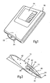
- Fig. 1 shows a portable blood glucose meter 18 for the use of such a measuring arrangement 1 for the so-called “spot monitoring", ie the self-determination of the blood sugar concentration at a given time by a subject.
- the device 18 has an inwardly tapered support 20 for finger positioning over a piercing opening 22 for the sampling or lancing element 10.
- the individual device components are activated in a fully automatic measurement process, so that the user finally on a display 24 a reading on obtains its current blood glucose level without the need for elaborate handling.
- Such Measurements can also be made on other parts of the body, for example in the less pain-sensitive arm or abdominal area, as well as tissue fluid or mixtures thereof being suitable for sampling in addition to capillary blood from the skin.
- the longitudinal slot 12 extends in the longitudinal direction of the shaft-shaped lancing element 10, for example over a length of 1 to 2 mm with a width of 100 to 200 microns.
- the distance to a piercing member forming the tip 26 may correspond approximately to the slot width.
- the liquid is absorbed on both sides via the opposite side openings 28, 30 of the longitudinal slot 12.
- the slot length in the lancing direction is dimensioned so that a distal slot portion 32 projects into the skin of the body part 14 and a proximal slot portion 34 is located outside the skin.
- the distal shaft portion 36 engaging in the body can be made "thin", ie tapered in cross section, while the proximal shaft portion 38 remaining outside the body has an expanded cross section or a comparatively larger thickness, by a sufficiently large amount of fluid to be able to collect.
- the amount of liquid corresponding to the slot volume may be 10 to 20 nanoliters, wherein the partial volume of the longitudinal slot 12 located in the body comprises, for example, a volume fraction of 20%.
- a wire is first processed as a starting material in a defined orientation by grinding processes, wherein the differently angled ground surfaces 40, 42 are produced. Then, in this surface structure, the longitudinal slot 12 is expediently introduced into the same processing station while maintaining the rotational orientation by means of a suitably positioned laser.
- An important production detail lies in the fact that the laser energy and / or the travel speed of the laser beam are regulated as a function of the cutting position; This makes it possible to design tapered openings or to compensate for different material thicknesses.
- the processing time can be kept sufficiently short for mass production, for example in the range of 1 sec.
- the mechanical tolerances can be kept low, for example in the range of 10 microns, with wall slopes of almost 90 ° can be reached.
- the laser treatment can create hydrophilic surfaces which may be further improved by a chemical post-treatment.
- the lancets 10 thus created can be oriented in a plastic holder. This can e.g. come from a roll, and by clipping, hot forming, etc., the connection to the lancet can be done in the correct position.
- the plastic holder may have a coupling piece so that the lancets can be gripped and moved in the device 18.
- Fig. 3 shows a combined system of sampling element (lancing element 10) and sample receiving element 16.
- the sampling takes place by reciprocating piercing movement of the lancing element 10, wherein at the proximal shaft portion 44, a suitable drive is positively coupled.
- the sample receiving element 16 held stationary during the lancing process is part of a push guide for the piercing element 10 and has a test field 46 for receiving the body fluid 48 previously collected in the longitudinal slot 12.
- the piercing element 10 thus fulfills a feeder function as a "shuttle" during sample collection, while the actual detection of the analyte takes place on the sample receiving element 16 not in contact with the body part 14.
- the glucose detection on the test field or reagent carrier 46 can be carried out photometrically by reflection through the transparent cover window 52, so that the blood liquid 48 in the compartment 50 remains hygienically separated from the device parts. Also conceivable are other detection techniques, for example via fluorescence or electrochemical detection.
- the essential steps of the sample transfer are illustrated in more detail.
- the piercing element 10 is protected in the magazine compartment 50, which can be sealed at the front by a piercing film.
- the puncture movement in the body part 14 takes place as quickly as possible for reasons of pain, it being possible, if appropriate, to control a slightly withdrawn collecting position from the maximum puncturing depth.
- the distal slot section 32 advantageously projects into the interior of the skin, while the proximal slot section 34 outside thereof performs a venting function.
- the blood fluid obtained in the puncture channel can flow into the collecting slot 12 on both sides in a short collecting time and efficiently fill the entire slot volume.
- the slot 12 is spatially separated from the sample receiving element 16 so that there is no fluidic connection therebetween and the detection reagents are not in the inside of the body can get.
- the lancing element 10 is withdrawn again until the upper side opening 28 of the slot 12 passes under the test field 46.
- This can, for example, have a greater capillary attractiveness than the slot 12 for an automatic transfer of the absorbed blood through a fleece structure.
- the liquid transfer is supported by, according to FIG. 4d), a membrane 54 as a displacement means for the collected liquid is pressed in at the lower slot opening 30.
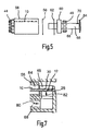
- FIGS. 5 to 7 also implements this principle, wherein a special magazine and actuation is provided.
- the lancing elements 10 are stored in a lancet drum 56, on the rear end side of which the coupling pieces 44 protrude for the drive coupling, while the front (distal) end side is sealed by a piercing foil 58.
- a separate test strip drum 60 can be fitted via insertion slots with test strips 46, which are then shielded by a film 62 and a front cover 64 against the environment in particular against ingress of moisture.
- the front cover 64 is seated on a hollow drum axis 66, which at the same time forms an air passage 68 for a pneumatic actuation via the shell-side blow opening 70. Due to the separate magazining different requirements can be taken care of.
- the piercing elements 10 which come into contact with the body can be suitably sterilized in the lancet drum 56 by high-energy radiation, while the radiation-sensitive test chemistry remains protected against external influences in the test strip drum 60 and does not come into physical contact during the piercing process.
- the magazines 56, 60 in the installed state are axially coupled on the drum axis 66, so that in each case one lancing element 10 and one test strip 46 are associated with one another.
- a magazine receptacle 72 within the device 18 enables the compressed air to be applied to the air passage 68 and the lancing drive of the lancing element 10 respectively coupled to a drive ram 74 in coaxial alignment with the finger cone 20 (FIG. 6a).
- the feed advances the actuated piercing element 10 pierces the upstream chamber 76 of the associated test strip 46 and reaches through the cone opening 22 through the maximum feed position (line in Fig. 6b) at a distance covered by about 10 mm.
- the blood intake via the slot 12 then takes place as described above.
- the transfer position shown in Fig. 6c is approached, in which the Slot 10 is aligned in its forward direction with the test strip 46.
- a targeted transfer of the collected liquid to the test strip 46 is possible in the transfer position.
- an air blast is triggered via the air passage 68 in the direction of the arrows 80, 82, which impinges the slot 12 on the facing side opening 28, so that the blood fluid is displaced over the opposite side opening 30 onto the test strip 46.
- the glucose detection can then be carried out reflectometrically via a device optics, not shown.
- the contaminated piercing element 10 is completely withdrawn into the receiving chamber 84 of the drum magazine 56 and brought by drum rotation, the next function pair 10, 46 in readiness.
Abstract
Description
Die Erfindung betrifft eine Anordnung zum Aufnehmen von Körperflüssigkeiten wie Blut, mit einem vorzugsweise mit einem Stechorgan zum Einstechen in ein Körperteil versehenen Probenentnahmeelement, das einen Sammelbereich zum Sammeln von durch einen Einstich erhaltener Körperflüssigkeit aufweist. Die Erfindung betrifft weiter ein Verfahren zur Herstellung eines solchen Probenentnahmeelements.The invention relates to an arrangement for receiving body fluids such as blood, having a sampling element preferably provided with a piercing member for piercing a body part, which has a collecting area for collecting body fluid obtained by a puncture. The invention further relates to a method for producing such a sampling element.
In einer früheren Anmeldung
Ausgehend hiervon liegt der Erfindung die Aufgabe zugrunde, die im Stand der Technik bekannten Systeme weiter zu entwickeln und eine Anordnung der eingangs angegebenen Art im Sinne einer verbesserten Probenaufnahme zu optimieren, wobei ein Erfindungsziel auch in einer vereinfachten Herstellung besteht.Proceeding from this, the invention is based on the object, known in the prior art systems to develop further and to optimize an arrangement of the type specified in the sense of improved sample recording, with a goal of the invention also consists in a simplified production.
Zur Lösung dieser Aufgabe wird die in den unabhängigen Patentansprüchen angegebene Merkmalskombination vorgeschlagen. Vorteilhafte Ausgestaltungen und Weiterbildungen der Erfindung ergeben sich aus den abhängigen Ansprüchen.To solve this problem, the combination of features specified in the independent claims is proposed. Advantageous embodiments and modifications of the invention will become apparent from the dependent claims.
Die Erfindung geht von dem Gedanken aus, eine möglichst zuverlässige kapillare Probenaufnahme durch einen beidseitig offenen Kapillarschlitz zu erreichen. Dementsprechend wird erfindungsgemäß vorgeschlagen, dass der Sammelbereich durch einen als Kapillare langgestreckten, über Seitenöffnungen an dem Probenentnahmeelement beidseitig offenen Längsschlitz gebildet ist. Dadurch kann eine rasche Probenaufnahme von beiden Seiten in einem einheitlichen Volumen gewährleistet werden, wobei aufgrund der Kapillarwirkung keine äußere Einwirkung erforderlich ist. Besonders bevorzugt verläuft der Schlitz in Längs- bzw. Stechrichtung eines als Stechelement ausgebildeten Probenentnahmeelements. Denkbar ist aber auch eine Probenaufnahme nach Erzeugung eines Einstichs mittels eines gesonderten Stechapparats. Im Vergleich zu röhrenförmigen oder halboffenen Kapillaren wird durch die offene Schlitzgestaltung auch die Gefahr von Blockierungen durch Gewebebestandteile weiter verringert. Durch die beidseitige Öffnung kann zudem das weitere Probenhandling wesentlich verbessert werden, wobei ein weitgehend totvolumenfreier Transfer erreichbar ist.The invention is based on the idea of achieving the most reliable capillary sample taking possible through a capillary slot that is open on both sides. Accordingly, it is proposed according to the invention that the collecting area is formed by a longitudinal slot which is elongate as a capillary and is opened on both sides by lateral openings on the sampling element. As a result, a rapid sample absorption can be ensured from both sides in a uniform volume, whereby due to the capillary action no external action is required. Particularly preferably, the slot extends in the longitudinal or piercing direction of a sampling element designed as a lancing element. It is also conceivable, however, a sample holder after generation of a puncture by means of a separate lancing device. Compared to tubular or semi-open capillaries, the open slot design further reduces the risk of tissue blockage blockages. In addition, the further sample handling can be substantially improved by opening on both sides, whereby a largely dead volume-free transfer can be achieved.
Gemäß einer bevorzugten Ausgestaltung der Erfindung ist die Länge des Längsschlitzes so bemessen, dass in einer Sammelstellung des Probenentnahmeelements der Längsschlitz teilweise innerhalb und teilweise außerhalb des Körperteils ist. Auf diese Weise kann bei der Flüssigkeitsaufnahme eine Entlüftungsfunktion des Schlitzes erreicht werden, und es steht zusätzliches Sammelvolumen zur Verfügung. In dieser Hinsicht ist es vorteilhaft, wenn der Längsschlitz beim Sammeln der Körperflüssigkeit einen in die Haut des Körperteils hineinragenden distalen Aufnahmeabschnitt und einen außerhalb der Haut befindlichen proximalen Entlüftungsabschnitt aufweist.According to a preferred embodiment of the invention, the length of the longitudinal slot is dimensioned such that in a collection position of the sampling element of the longitudinal slot is partially within and partially outside of the body part. In this way, a venting function of the slot can be achieved in the liquid intake, and there is additional collection volume available. In this regard, it is advantageous if the longitudinal slot has a distal receiving section protruding into the skin of the body part when collecting the body fluid and a proximal vent section located outside the skin.
Vorteilhafterweise besitzt der Längsschlitz eine Länge von 0,5 bis 4 mm, vorzugsweise von 1 bis 2 mm und eine Breite von weniger als 500 µm, vorzugsweise weniger als 100 µm. Weiter ist es von Vorteil, wenn der Längsschlitz im Abstand vorzugsweise von etwa 50 bis 200 µm zu einer das Stechorgan bildenden distalen Spitze des Probenentnahmeelements angeordnet ist.Advantageously, the longitudinal slot has a length of 0.5 to 4 mm, preferably 1 to 2 mm and a width of less than 500 microns, preferably less than 100 microns. Further, it is advantageous if the longitudinal slot is arranged at a distance of preferably from about 50 to 200 .mu.m to a piercing member forming the distal tip of the sampling element.
Um den bei einem Einstich empfundenen Schmerz zu reduzieren und gleichzeitig ein hinreichendes Aufnahmevolumen zu schaffen, kann das Probenentnahmeelement im Bereich des Längsschlitzes einen im Querschnitt verjüngten distalen Schaftabschnitt und einen im Querschnitt erweiterten proximalen Schaftabschnitt aufweisen.In order to reduce the pain felt at a puncture and at the same time a sufficient volume of admission In the region of the longitudinal slot, the sampling element can have a cross-sectionally tapered distal shaft section and a proximal shaft section which is widened in cross-section.
Ein auch hinsichtlich der Analyse weiter integriertes System sieht ein über den Sammelbereich mit Körperflüssigkeit beaufschlagbares, vorzugsweise mit einem Testfeld für einen Analyten in der Körperflüssigkeit versehenes Probenempfangselement vor. Hierbei ist es für einen schnellen und möglichst verlustfreien Flüssigkeitstransfer auf ein zuvor getrenntes Empfangselement von besonderem Vorteil, wenn eine Seitenöffnung als Auslass des Längsschlitzes mit dem Probenempfangselement in fluidischen Kontakt bringbar ist.A further system which is also integrated with regard to the analysis provides a sample receiving element which can be acted upon by the collecting area with body fluid and is preferably provided with a test field for an analyte in the body fluid. In this case, it is of particular advantage for a quick and loss-free liquid transfer to a previously separate receiving element if a side opening as an outlet of the longitudinal slot can be brought into fluidic contact with the sample receiving element.
Eine weitere Verbesserung in dieser Richtung wird dadurch erreicht, dass der Längsschlitz in der Sammelstellung des Probenentnahmeelements von dem Probenempfangselement räumlich und/oder fluidisch getrennt, und in einer Transferstellung des Probenentnahmeelements mit dem Probenempfangselement zum Transfer von Körperflüssigkeit über eine Seitenöffnung gekoppelt ist.A further improvement in this direction is achieved in that the longitudinal slot in the collection position of the sampling element of the sample receiving element spatially and / or fluidly separated, and is coupled in a transfer position of the sampling element with the sample receiving element for the transfer of body fluid via a side opening.
Hierbei ist es auch von Vorteil, wenn die dem Auslass gegenüberliegende Seitenöffnung des Längsschlitzes in einer Transferstellung an einen Aktuator zum Transfer der Körperflüssigkeit auf das Probenempfangselement angeschlossen ist.It is also advantageous if the side opening of the longitudinal slot opposite the outlet is connected in a transfer position to an actuator for transferring the body fluid to the sample receiving element.
Vorteilhafterweise wirkt der Aktuator über pneumatische und/oder mechanische Verdrängungsmittel auf die in dem Längsschlitz befindliche Körperflüssigkeit ein, wobei ein mechanischer Aktuator durch eine gegen den Längsschlitz deformierbare Membran gebildet sein kann. Günstig ist es auch, wenn der Aktuator eine an die von dem Probenempfangselement abgewandte Seitenöffnung des Längsschlitzes ankoppelbare Druckluftpassage aufweist.Advantageously, the actuator acts via pneumatic and / or mechanical displacement means on the body fluid located in the longitudinal slot, wherein a mechanical actuator may be formed by a deformable against the longitudinal slot membrane. It is also favorable if the actuator has a compressed air passage which can be coupled to the side opening of the longitudinal slot facing away from the sample receiving element.
Für einen möglichst vollständigen Flüssigkeitstransfer ist es vorteilhaft, wenn das Probenempfangselement eine größere Kapillarattraktion für die Körperflüssigkeit als der Längsschlitz aufweist.For as complete a fluid transfer as possible, it is advantageous if the sample receiving element has a larger capillary attraction for the body fluid than the longitudinal slot.
Eine weitere vorteilhafte Ausgestaltung sieht vor, dass das Probenentnahmeelement in einer Führung relativ zu dem Probenempfangselement beweglich gelagert ist.A further advantageous embodiment provides that the sampling element is mounted movably in a guide relative to the sample receiving element.
Weitere Gebrauchsvorteile für den Benutzer lassen sich dadurch erzielen, dass mehrere Probenentnahmeelemente in einem ersten Magazin und mehrere Probenempfangselemente in einem zweiten Magazin bevorratet sind, wobei die Magazine als gesonderte Einheiten zur paarweisen Kopplung der Probenentnahmeelemente und Probenempfangselemente miteinander verbindbar sind.Further usage advantages for the user can be achieved by storing a plurality of sampling elements in a first magazine and a plurality of sample receiving elements in a second magazine, wherein the magazines are connectable as separate units for pairwise coupling of the sampling elements and sample receiving elements.
Eine vorteilhafte Realisierungsmöglichkeit besteht darin, dass eine Mehrzahl von Probenentnahmeelementen in einem Magazin, vorzugsweise einem Trommelmagazin axial ausstoßbar angeordnet sind, und dass zugeordnete Probenempfangselemente vorzugsweise in Durchstoßkammern dem Magazin in Ausstoßrichtung vorgeordnet sind.An advantageous realization possibility is that a plurality of sampling elements in a magazine, preferably a drum magazine are axially ejected, and that associated sample receiving elements are preferably arranged upstream of the magazine in the ejection direction in puncture chambers.
Gegenstand der Erfindung ist auch ein tragbares Blutanalysegerät mit mindestens einer vorzugsweise als Einmalartikel ausgebildeten erfindungsgemäßen Sammelanordnung.The subject of the invention is also a portable blood analyzer with at least one collection device according to the invention, preferably designed as a disposable article.
In verfahrensmäßiger Hinsicht wird die eingangs genannte Aufgabe dadurch gelöst, dass in dem Probenentnahmeelement ein beidseitig offener Längsschlitz als Sammelbereich für die Körperflüssigkeit durch Laserschneiden gebildet wird.In procedural terms, the object mentioned in the introduction is achieved in that a longitudinal slot open on both sides is formed in the sampling element as a collection region for the body fluid by laser cutting.
Hierbei ist es günstig, wenn die Begrenzungsfläche des Längsschlitzes beim Laserschneiden hydrophiliert wird.It is advantageous if the boundary surface of the longitudinal slot is hydrophilized during laser cutting.
Eine weitere Verbesserung sieht vor, dass die Laserenergie und/oder die Verfahrgeschwindigkeit des Laserstrahls beim Laserschneiden positionsabhängig geregelt wird, so dass unterschiedliche Materialstärken besser berücksichtigt werden können.A further improvement provides that the laser energy and / or the travel speed of the laser beam during laser cutting is position-dependent controlled, so that different material thicknesses can be better taken into account.
Vorteilhafterweise beträgt die Bearbeitungszeit während des Laserschneidens weniger als 2 s, vorzugsweise etwa 1 s.Advantageously, the machining time during laser cutting is less than 2 s, preferably about 1 s.
Auch für eine erhöhte Kapillarwirkung ist es von Vorteil, wenn die Begrenzungskanten des Längsschlitzes mit einem Kantenwinkel von weniger als 100°, vorzugsweise etwa 90° gebildet werden.Also, for an increased capillary effect, it is advantageous if the boundary edges of the longitudinal slot are formed with an edge angle of less than 100 °, preferably about 90 °.
Eine weitere vorteilhafte Verfahrensweise sieht vor, dass an dem Probenentnahmeelement ein scharfes Stechorgan durch Schleifen erzeugt wird, so dass das Stechorgan durch mindestens einen Flachschliff begrenzt wird. Hierbei ist es auch von Vorteil, wenn ein Draht oder ein flaches Band als Ausgangsmaterial bearbeitet wird.A further advantageous procedure provides that a sharp lancing member is produced by grinding on the sampling element, so that the lancing member is limited by at least one flat cut. It is also advantageous if a wire or a flat strip is processed as a starting material.
Im Folgenden wird die Erfindung anhand der in der Zeichnung schematisch dargestellten Ausführungsbeispiele näher erläutert. Es zeigen
- Fig. 1
- ein Handgerät zur Blutzuckermessung in einer perspektivischen Ansicht;
- Fig. 2
- ein Stechelement mit einem Längsschlitz zur Blutaufnahme in einer perspektivischen Ansicht;
- Fig. 3
- ein integriertes System mit Stechelement und Testelement in verschiedenen Prozessschritten in der Perspektive;
- Fig. 4
- einen Fig. 3 entsprechenden Messablauf im Axialschnitt;
- Fig. 5
- ein integriertes Magazinsystem für ein Blutzuckermessgerät in einer Explosionsdarstellung;
- Fig. 6
- den Messablauf beim Einsatz des Magazinsystems nach Fig. 5 im Längsschnitt;
- Fig. 7
- eine ausschnittsweise Vergrößerung der Fig. 6c.
- Fig. 1
- a hand-held device for blood glucose measurement in a perspective view;
- Fig. 2
- a lancing element with a longitudinal slot for blood uptake in a perspective view;
- Fig. 3
- an integrated system with lancing element and test element in different process steps in perspective;
- Fig. 4
- a measuring sequence corresponding to FIG. 3 in axial section;
- Fig. 5
- an integrated magazine system for a blood glucose meter in an exploded view;
- Fig. 6
- the measurement process when using the magazine system of Figure 5 in longitudinal section.
- Fig. 7
- a partial enlargement of Fig. 6c.
Die in der Zeichnung dargestellte Messanordnung 1 umfasst mindestens ein Probenentnahmeelement 10 mit einem als Längsschlitz 12 ausgebildeten Sammelbereich zum Sammeln von an einer Einstichstelle aus einem Körperteil 14 erhaltener Körperflüssigkeit und ein mit dem Längsschlitz in fluidische Verbindung bringbares Probenempfangselement 16 zum Blutzuckernachweis.The measuring
Fig. 1 zeigt ein portables Blutzuckermessgerät 18 für den Einsatz einer solchen Messanordnung 1 für das so genannte "Spot-Monitoring", d.h. die Selbstbestimmung der Blutzuckerkonzentration zu einer gegebenen Zeit durch einen Probanden. Zu diesem Zweck weist das Gerät 18 eine nach innen konische Auflage 20 zur Fingerpositionierung über einer Durchstechöffnung 22 für das Probenentnahme- bzw. Stechelement 10. Die einzelnen Gerätekomponenten werden in einem vollautomatischen Messablauf aktiviert, so dass der Benutzer schließlich auf einer Anzeige 24 einen Messwert über seinen momentanen Blutglukosespiegel erhält, ohne dass eine aufwändige Handhabung erforderlich wäre. Generell können solche Messungen auch an anderen Körperteilen, beispielsweise im weniger schmerzempfindlichen Arm- oder Bauchbereich vorgenommen werden, wobei als Körperflüssigkeit für die Probennahme neben Kapillarblut aus der Haut auch Gewebeflüssigkeit oder Mischungen davon in Frage kommen.Fig. 1 shows a portable
Wie aus Fig. 2 zu ersehen, erstreckt sich der Längsschlitz 12 in Längsrichtung des schaftförmigen Stechelements 10, beispielsweise über eine Länge von 1 bis 2 mm bei einer Breite von 100 bis 200 µm. Der Abstand zu einer das Stechorgan bildenden Spitze 26 kann etwa der Schlitzbreite entsprechen. Auf diese Weise wird eine Kapillaraufnahme gebildet, in welche die beim Einstich in dem Körperteil 14 zugängliche Körperflüssigkeit aufgrund von Kapillarwirkung selbsttätig einströmt.As can be seen from Fig. 2, the
Die Flüssigkeitsaufnahme erfolgt beidseitig über die einander gegenüberliegenden Seitenöffnungen 28, 30 des Längsschlitzes 12. Hierbei ist die Schlitzlänge in Stechrichtung so bemessen, dass ein distaler Schlitzabschnitt 32 in die Haut des Körperteils 14 hineinragt und ein proximaler Schlitzabschnitt 34 sich außerhalb der Haut befindet. Zur Schmerzverringerung kann der in den Körper eingreifende distale Schaftabschnitt 36 "dünn", d.h. im Querschnitt verjüngt ausgeführt sein, während der außerhalb des Körpers verbleibende proximale Schaftabschnitt 38 demgegenüber einen erweiterten Querschnitt bzw. eine vergleichsweise größere Dicke aufweist, um eine hinreichend große Flüssigkeitsmenge sammeln zu können. Beispielsweise kann die Flüssigkeitsmenge entsprechend dem Schlitzvolumen 10 bis 20 Nanoliter betragen, wobei das im Körper befindliche Teilvolumen des Längsschlitzes 12 beispielsweise einen Volumenanteil von 20% umfasst.The liquid is absorbed on both sides via the
Bei der Herstellung solcher Stechelemente 10 wird zunächst ein Draht als Ausgangsmaterial in einer definierten Ausrichtung durch Schleifprozesse bearbeitet, wobei die unterschiedlich abgewinkelten Schliffflächen 40, 42 erzeugt werden. Sodann wird in dieser Flächenstruktur zweckmäßig in derselben Bearbeitungsstation unter Beibehaltung der Drehausrichtung mittels eines geeignet positionierten Lasers der Längsschlitz 12 eingebracht. Ein wichtiges Produktionsdetail liegt darin, dass die Laserenergie und/oder die Verfahrgeschwindigkeit des Laserstrahls in Abhängigkeit von der Schneidposition geregelt werden; damit lassen sich zulaufende Öffnungen gestalten oder auch unterschiedliche Materialdicken kompensieren.In the production of such piercing
Für den Schlitzdurchbruch sind nur wenige Bewegungen des Laserstrahls nötig, und die Bearbeitungszeit kann für eine Massenfertigung ausreichend kurz gehalten werden, beispielsweise im Bereich von 1 sec. Ebenso können die mechanischen Toleranzen gering gehalten werden, beispielsweise im Bereich von 10 µm, wobei Wandsteilheiten von nahezu 90° erreichbar sind. Zudem können durch die Laserbehandlung hydrophile Oberflächen geschaffen werden, die sich gegebenenfalls durch eine chemische Nachbehandlung weiter verbessern lassen.For the slot breakthrough only a few movements of the laser beam are necessary, and the processing time can be kept sufficiently short for mass production, for example in the range of 1 sec. Similarly, the mechanical tolerances can be kept low, for example in the range of 10 microns, with wall slopes of almost 90 ° can be reached. In addition, the laser treatment can create hydrophilic surfaces which may be further improved by a chemical post-treatment.
Die solchermaßen geschaffenen Lanzetten 10 können orientiert in einen Kunststoffhalter eingebracht werden. Dieser kann z.B. von einer Rolle kommen, und durch Einklipsen, Warmverformen etc. kann die Verbindung zur Lanzette lagerichtig erfolgen. Der Kunststoffhalter kann ein Kopplungsstück aufweisen, damit sich die Lanzetten im Gerät 18 greifen und bewegen lassen.The
Fig. 3 zeigt ein kombiniertes System aus Probenentnahmeelement (Stechelement 10) und Probenempfangselement 16. Die Probenentnahme erfolgt durch hin- und hergehende Stechbewegung des Stechelements 10, wobei an dem proximalen Schaftteil 44 ein geeigneter Antrieb formschlüssig angekoppelt wird. Das während des Stechvorgangs gerätefest gehaltene Probenempfangselement 16 ist Teil einer Schubführung für das Stechelement 10 und weist ein Testfeld 46 zum Aufnehmen der zuvor in dem Längsschlitz 12 gesammelten Körperflüssigkeit 48 auf. Das Stechelement 10 erfüllt somit eine Zubringerfunktion als "Shuttle" bei der Probengewinnung, während der eigentliche Nachweis des Analyten auf dem mit dem Körperteil 14 nicht in Berührung kommenden Probenempfangselement 16 erfolgt. Dieses kann auch als Komponente eines eine Mehrzahl von abgeteilten Kompartimenten 50 umfassenden Magazins vorgesehen sein, welches sich als Verbrauchsartikel in das Gerät 18 einsetzen und mit den verbrauchten Stechelementen wieder entsorgen lässt. Der Glucosenachweis auf dem Testfeld bzw. Reagenzträger 46 kann photometrisch über Reflexion durch das transparente Deckfenster 52 hindurch erfolgen, so dass die Blutflüssigkeit 48 in dem Kompartiment 50 von den Geräteteilen hygienisch getrennt bleibt. Denkbar sind auch andere Nachweistechniken, beispielsweise über Flüoreszenz oder elektrochemische Erfassung.Fig. 3 shows a combined system of sampling element (lancing element 10) and
In Fig. 4 sind die wesentlichen Schritte des Probentransfers nochmals näher veranschaulicht. In der Ausgangsstellung (4a) befindet sich das Stechelement 10 geschützt in dem Magazinfach 50, welches frontseitig durch eine Durchstechfolie versiegelt sein kann. Die Einstichbewegung in das Körperteil 14 (beispielsweise eine Fingerkuppe) erfolgt aus Schmerzgründen möglichst rasch, wobei gegebenenfalls aus der maximalen Einstechtiefe eine leicht zurückgezogene Sammelposition angesteuert werden kann. Vorteilhafterweise ragt für den Sammelvorgang entsprechend (4b) der distale Schlitzabschnitt 32 in das Hautinnere, während der proximale Schlitzabschnitt 34 außerhalb davon eine Entlüftungsfunktion erfüllt. Somit kann die im Einstichkanal gewonnene Blutflüssigkeit in kurzer Sammelzeit beidseitig in den Sammelschlitz 12 einströmen und effizient das gesamte Schlitzvolumen füllen. In der Sammelstellung ist der Schlitz 12 von dem Probenempfangselement 16 räumlich so getrennt, dass keine fluidische Verbindung dazwischen besteht und die Nachweisreagenzien nicht in das Körperinnere gelangen können. Dies erlaubt es auch, den Nachweisvorgang gezielt zu starten und den Messverlauf als solchen auszuwerten. Zu diesem Zweck wird entsprechend Fig. 4c) das Stechelement 10 wieder zurückgezogen, bis die obere Seitenöffnung 28 des Schlitzes 12 unter das Testfeld 46 gelangt. Dieses kann beispielsweise durch eine vliesstruktur eine größere Kapillarattraktivität als der Schlitz 12 für einen selbsttätigen Transfer des aufgenommenen Blutes besitzen. Bevorzugt wird jedoch der Flüssigkeitstransfer unterstützt, indem gemäß Fig. 4d) an der unteren Schlitzöffnung 30 eine Membran 54 als Verdrängungsmittel für die gesammelte Flüssigkeit eingedrückt wird. Der Fluidtransfer erfolgt also über die gesamte Schlitzlänge mit kurzem Weg quer zur Stechrichtung des Stechelements 10.
Auch die in Fig. 5 bis 7 gezeigte Ausführungsform verwirklicht dieses Prinzip, wobei eine spezielle Magazinierung und Aktuierung vorgesehen ist. Gemäß Fig. 5 sind die Stechelemente 10 in einer Lanzettentrommel 56 magaziniert, an deren hinterer Stirnseite die Kopplungsstücke 44 für die Antriebskopplung abstehen, während die vordere (distale) Stirnseite durch eine Durchstechfolie 58 versiegelt wird. Eine gesonderte Teststreifentrommel 60 kann über Einschubschlitze mit Teststreifen 46 bestückt werden, welche dann durch eine Folie 62 und einen Stirndeckel 64 gegenüber der Umgebung insbesondere gegen Feuchtigkeitszutritt abgeschirmt werden. Der Stirndeckel 64 sitzt auf einer Trommelhohlachse 66, welche zugleich eine Luftpassage 68 für eine pneumatische Aktuierung über die mantelseitige Blasöffnung 70 bildet. Durch die gesonderte Magazinierung kann unterschiedlichen Anforderungen Sorge getragen werden. Die mit dem Körper in Kontakt kommenden Stechelemente 10 lassen sich in der Lanzettentrommel 56 zweckmäßig durch energiereiche Strahlung sterilisieren, während die strahlungsempfindliche Testchemie unabhängig davon in der Teststreifentrommel 60 gegen äußere Einflüsse geschützt bleibt und beim Stechvorgang auch nicht in Körperberührung gelangt.4, the essential steps of the sample transfer are illustrated in more detail. In the initial position (4a), the piercing
The embodiment shown in FIGS. 5 to 7 also implements this principle, wherein a special magazine and actuation is provided. According to FIG. 5, the lancing
Wie aus Fig. 6 ersichtlich, sind die Magazine 56, 60 im Einbauzustand auf der Trommelachse 66 axial gekoppelt, so dass jeweils ein Stechelement 10 und ein Teststreifen 46 einander zugeordnet sind. Eine Magazinaufnahme 72 innerhalb des Geräts 18 ermöglicht die Druckluftbeaufschlagung der Luftpassage 68 und den Stechantrieb des jeweils an einen Antriebsstößel 74 angekoppelten Stechelements 10 in koaxialer Ausrichtung zu dem Fingerkonus 20 (Fig. 6a). Beim Stechvorschub durchstößt das betätigte Stechelement 10 die vorgelagerte Kammer 76 des zugeordneten Teststreifens 46 und erreicht durch die Konusöffnung 22 hindurch die maximale Vorschubposition (Linie in Fig. 6b) bei einem zurückgelegten Weg von etwa 10 mm. Die Blutaufnahme über den Schlitz 12 erfolgt dann wie oben beschrieben. Anschließend wird bei der Rückbewegung des Stechelements 10 die in Fig. 6c gezeigte Transferposition angefahren, in welcher der Schlitz 10 in seiner Durchlassrichtung mit dem Teststreifen 46 fluchtet.As can be seen from FIG. 6, the
Wie am besten aus dem vergrößerten Ausschnitt gemäß Fig. 7 ersichtlich, ist in der Transferposition eine gezielte Übergabe der gesammelten Flüssigkeit auf den Teststreifen 46 möglich. Zu diesem Zweck wird über die Luftpassage 68 in Richtung der Pfeile 80, 82 ein Luftstoß ausgelöst, welcher den Schlitz 12 an der zugewandten Seitenöffnung 28 beaufschlagt, so dass die Blutflüssigkeit über die gegenüberliegende Seitenöffnung 30 auf den Teststreifen 46 verdrängt wird. Der Glucosenachweis kann dann über eine nicht gezeigte Geräteoptik reflektometrisch durchgeführt werden. Anschließend wird das kontaminierte Stechelement 10 in die Aufnahmekammer 84 des Trommelmagazins 56 vollständig zurückgezogen und durch Trommeldrehung das nächste Funktionspaar 10, 46 in Bereitschaft gebracht.As best seen in the enlarged section of FIG. 7, a targeted transfer of the collected liquid to the
Claims (26)
Priority Applications (8)
| Application Number | Priority Date | Filing Date | Title |
|---|---|---|---|
| EP05019055A EP1759633A1 (en) | 2005-09-01 | 2005-09-01 | Device for sampling bodily fluids and its fabrication method |
| PCT/EP2006/008436 WO2007025713A1 (en) | 2005-09-01 | 2006-08-29 | Assembly for receiving body fluids, and method for the production thereof |
| EP06777103.0A EP1921993B1 (en) | 2005-09-01 | 2006-08-29 | Assembly for receiving body fluids |
| CN2006800316915A CN101312689B (en) | 2005-09-01 | 2006-08-29 | Assembly for receiving body fluids, and method for the production thereof |
| JP2008528404A JP4825268B2 (en) | 2005-09-01 | 2006-08-29 | Structure, system for collecting body fluid, and method for manufacturing the same |
| CA2619914A CA2619914C (en) | 2005-09-01 | 2006-08-29 | Assembly for receiving body fluids and method for the production thereof |
| US12/037,197 US8142366B2 (en) | 2005-09-01 | 2008-02-26 | Assembly for receiving body fluids, and method for the production thereof |
| HK09104556.9A HK1126105A1 (en) | 2005-09-01 | 2009-05-19 | Assembly for receiving body fluids, and method for the production thereof |
Applications Claiming Priority (1)
| Application Number | Priority Date | Filing Date | Title |
|---|---|---|---|
| EP05019055A EP1759633A1 (en) | 2005-09-01 | 2005-09-01 | Device for sampling bodily fluids and its fabrication method |
Publications (1)
| Publication Number | Publication Date |
|---|---|
| EP1759633A1 true EP1759633A1 (en) | 2007-03-07 |
Family
ID=35613911
Family Applications (2)
| Application Number | Title | Priority Date | Filing Date |
|---|---|---|---|
| EP05019055A Withdrawn EP1759633A1 (en) | 2005-09-01 | 2005-09-01 | Device for sampling bodily fluids and its fabrication method |
| EP06777103.0A Not-in-force EP1921993B1 (en) | 2005-09-01 | 2006-08-29 | Assembly for receiving body fluids |
Family Applications After (1)
| Application Number | Title | Priority Date | Filing Date |
|---|---|---|---|
| EP06777103.0A Not-in-force EP1921993B1 (en) | 2005-09-01 | 2006-08-29 | Assembly for receiving body fluids |
Country Status (7)
| Country | Link |
|---|---|
| US (1) | US8142366B2 (en) |
| EP (2) | EP1759633A1 (en) |
| JP (1) | JP4825268B2 (en) |
| CN (1) | CN101312689B (en) |
| CA (1) | CA2619914C (en) |
| HK (1) | HK1126105A1 (en) |
| WO (1) | WO2007025713A1 (en) |
Cited By (5)
| Publication number | Priority date | Publication date | Assignee | Title |
|---|---|---|---|---|
| EP1911394A1 (en) * | 2006-10-14 | 2008-04-16 | Roche Diagnostics GmbH | Lancet with capillar channel |
| EP1977686A1 (en) * | 2007-04-04 | 2008-10-08 | F.Hoffmann-La Roche Ag | Disposable diagnostic article |
| WO2009037192A1 (en) * | 2007-09-17 | 2009-03-26 | F. Hoffmann-La Roche Ag | Disposable device for analyzing body fluid |
| EP2545955A1 (en) * | 2010-03-10 | 2013-01-16 | Lightnix, Inc. | Medical needle and puncturing instrument |
| EP2664278A3 (en) * | 2009-07-10 | 2014-02-19 | Roche Diagniostics GmbH | Lance |
Families Citing this family (15)
| Publication number | Priority date | Publication date | Assignee | Title |
|---|---|---|---|---|
| EP1868502B1 (en) * | 2005-04-04 | 2010-07-07 | Facet Technologies, LLC | Narrow-profile lancing device |
| EP1970006A1 (en) * | 2007-03-14 | 2008-09-17 | Roche Diagnostics GmbH | Analysis system for determining a analyte in a body fluid and disposable integrated sample extraction and analysis element |
| US9186097B2 (en) * | 2007-09-17 | 2015-11-17 | Roche Diabetes Care, Inc. | Body fluid lancing, acquiring, and testing cartridge design |
| US8961431B2 (en) * | 2009-09-28 | 2015-02-24 | Roche Diagnostics Operations, Inc. | Body fluid lancing, acquiring, and testing cartridge design |
| WO2009046957A2 (en) * | 2007-10-08 | 2009-04-16 | Roche Diagnostics Gmbh | Analysis system for automatic skin prick analysis |
| EP2087840A1 (en) | 2008-02-11 | 2009-08-12 | F.Hoffmann-La Roche Ag | Device and method for removing bodily fluids |
| EP2130493B1 (en) * | 2008-06-07 | 2013-09-25 | Roche Diagnostics GmbH | Analysis system for detecting an analyte in a bodily fluid, cartridge for an analytic device and method for manufacturing a cartridge for an analysis system. |
| EP2208459A1 (en) * | 2009-01-16 | 2010-07-21 | F. Hoffmann-Roche AG | System and method for analysing a body fluid |
| EP2263526A1 (en) | 2009-06-19 | 2010-12-22 | Roche Diagnostics GmbH | Piercing system |
| US9717452B2 (en) * | 2010-12-30 | 2017-08-01 | Roche Diabetes Care, Inc. | Handheld medical diagnostic devices with lancing speed control |
| US8852123B2 (en) * | 2010-12-30 | 2014-10-07 | Roche Diagnostics Operations, Inc. | Handheld medical diagnostic devices housing with sample transfer |
| WO2014050209A1 (en) * | 2012-09-28 | 2014-04-03 | 株式会社日立ハイテクインスツルメンツ | Component supply unit |
| CN108601565B (en) | 2015-12-11 | 2021-09-07 | 巴布森诊断公司 | Sample container and method for separating serum or plasma from whole blood |
| US20190320960A1 (en) * | 2016-11-14 | 2019-10-24 | Siemens Healthcare Diagnostics Inc. | Blood collection device with integrated absorbent material |
| USD885572S1 (en) * | 2018-03-12 | 2020-05-26 | Olympus Corporation | Biopsy needle |
Citations (6)
| Publication number | Priority date | Publication date | Assignee | Title |
|---|---|---|---|---|
| EP1284121A2 (en) * | 2001-08-06 | 2003-02-19 | Lifescan, Inc. | Physiological sample collection devices and methods of using the same |
| US20030171699A1 (en) * | 2002-03-05 | 2003-09-11 | Bayer Healthcare, Llc | Fluid collection apparatus having an integrated lance and reaction area |
| EP1360933A1 (en) * | 2002-05-09 | 2003-11-12 | Lifescan, Inc. | Physiological sample collection devices and methods of using the same |
| US20040072357A1 (en) * | 2000-12-19 | 2004-04-15 | Matthias Stiene | Device for measuring blood coagulation and method thereof |
| WO2004066822A2 (en) * | 2003-01-29 | 2004-08-12 | Roche Diagnostics Gmbh | Integrated lancing test strip |
| WO2005084546A2 (en) | 2004-03-06 | 2005-09-15 | Roche Diagnostics Gmbh | Body fluid sampling device |
Family Cites Families (6)
| Publication number | Priority date | Publication date | Assignee | Title |
|---|---|---|---|---|
| DE10047419A1 (en) * | 2000-09-26 | 2002-04-11 | Roche Diagnostics Gmbh | Lancet system |
| DE60213822T2 (en) * | 2001-06-08 | 2007-08-02 | Roche Diagnostics Gmbh | REMOVAL DEVICE FOR BODY FLUIDS AND TEST MEDIA CASSETTE |
| DE10134650B4 (en) * | 2001-07-20 | 2009-12-03 | Roche Diagnostics Gmbh | System for taking small amounts of body fluid |
| US7645241B2 (en) * | 2004-09-09 | 2010-01-12 | Roche Diagnostics Operations, Inc. | Device for sampling bodily fluids |
| US7604604B2 (en) * | 2004-09-09 | 2009-10-20 | Roche Diagnostics Operations, Inc. | Device for sampling bodily fluids |
| US7955271B2 (en) * | 2006-10-13 | 2011-06-07 | Roche Diagnostics Operations, Inc. | Tape transport lance sampler |
-
2005
- 2005-09-01 EP EP05019055A patent/EP1759633A1/en not_active Withdrawn
-
2006
- 2006-08-29 JP JP2008528404A patent/JP4825268B2/en not_active Expired - Fee Related
- 2006-08-29 WO PCT/EP2006/008436 patent/WO2007025713A1/en active Application Filing
- 2006-08-29 CA CA2619914A patent/CA2619914C/en active Active
- 2006-08-29 EP EP06777103.0A patent/EP1921993B1/en not_active Not-in-force
- 2006-08-29 CN CN2006800316915A patent/CN101312689B/en not_active Expired - Fee Related
-
2008
- 2008-02-26 US US12/037,197 patent/US8142366B2/en active Active
-
2009
- 2009-05-19 HK HK09104556.9A patent/HK1126105A1/en not_active IP Right Cessation
Patent Citations (6)
| Publication number | Priority date | Publication date | Assignee | Title |
|---|---|---|---|---|
| US20040072357A1 (en) * | 2000-12-19 | 2004-04-15 | Matthias Stiene | Device for measuring blood coagulation and method thereof |
| EP1284121A2 (en) * | 2001-08-06 | 2003-02-19 | Lifescan, Inc. | Physiological sample collection devices and methods of using the same |
| US20030171699A1 (en) * | 2002-03-05 | 2003-09-11 | Bayer Healthcare, Llc | Fluid collection apparatus having an integrated lance and reaction area |
| EP1360933A1 (en) * | 2002-05-09 | 2003-11-12 | Lifescan, Inc. | Physiological sample collection devices and methods of using the same |
| WO2004066822A2 (en) * | 2003-01-29 | 2004-08-12 | Roche Diagnostics Gmbh | Integrated lancing test strip |
| WO2005084546A2 (en) | 2004-03-06 | 2005-09-15 | Roche Diagnostics Gmbh | Body fluid sampling device |
Cited By (11)
| Publication number | Priority date | Publication date | Assignee | Title |
|---|---|---|---|---|
| EP1911394A1 (en) * | 2006-10-14 | 2008-04-16 | Roche Diagnostics GmbH | Lancet with capillar channel |
| WO2008043498A1 (en) * | 2006-10-14 | 2008-04-17 | Roche Diagnostics Gmbh | Lancet with capillary channel |
| EP1977686A1 (en) * | 2007-04-04 | 2008-10-08 | F.Hoffmann-La Roche Ag | Disposable diagnostic article |
| WO2008122541A1 (en) * | 2007-04-04 | 2008-10-16 | F. Hoffmann-La Roche Ag | Disposable diagnostic article |
| US8298159B2 (en) | 2007-04-04 | 2012-10-30 | Roche Diagnostics Operations, Inc. | Disposable diagnostic article |
| WO2009037192A1 (en) * | 2007-09-17 | 2009-03-26 | F. Hoffmann-La Roche Ag | Disposable device for analyzing body fluid |
| CN101873827B (en) * | 2007-09-17 | 2012-07-04 | 霍夫曼-拉罗奇有限公司 | Disposable device for analyzing body fluid |
| EP2664278A3 (en) * | 2009-07-10 | 2014-02-19 | Roche Diagniostics GmbH | Lance |
| EP2545955A1 (en) * | 2010-03-10 | 2013-01-16 | Lightnix, Inc. | Medical needle and puncturing instrument |
| EP2545955A4 (en) * | 2010-03-10 | 2013-07-24 | Lightnix Inc | Medical needle and puncturing instrument |
| US8998859B2 (en) | 2010-03-10 | 2015-04-07 | Lightnix, Inc. | Medical needle and puncturing instrument |
Also Published As
| Publication number | Publication date |
|---|---|
| JP4825268B2 (en) | 2011-11-30 |
| CA2619914A1 (en) | 2007-03-08 |
| HK1126105A1 (en) | 2009-08-28 |
| JP2009506810A (en) | 2009-02-19 |
| CN101312689A (en) | 2008-11-26 |
| US20080200887A1 (en) | 2008-08-21 |
| WO2007025713A1 (en) | 2007-03-08 |
| EP1921993B1 (en) | 2016-09-28 |
| CN101312689B (en) | 2013-03-27 |
| CA2619914C (en) | 2012-08-28 |
| EP1921993A1 (en) | 2008-05-21 |
| US8142366B2 (en) | 2012-03-27 |
Similar Documents
| Publication | Publication Date | Title |
|---|---|---|
| EP1921993B1 (en) | Assembly for receiving body fluids | |
| EP1933695B1 (en) | Test element and test system for examining a body fluid | |
| EP2129289B1 (en) | Analytical system for determining an analyte in a body fluid and disposable integrated sample collection and analytical element | |
| DE60303987T2 (en) | Liquid sensor with integrated lancet | |
| DE69733836T2 (en) | BODY FLUID DETECTION AND ANALYSIS DEVICE | |
| EP1287785B1 (en) | Analyzing means with lancet and test element | |
| EP2236082B1 (en) | Device to obtain and analyse a blood sample | |
| EP1838239B1 (en) | Testing unit for carrying out a one-time testing of a body fluid | |
| EP1997429B1 (en) | Flexible Lancet in a Lancet System | |
| EP2101639A2 (en) | Device and method for analyzing body fluids | |
| EP2101646B1 (en) | Pricking device | |
| EP2173240B1 (en) | Disposable diagnostic article | |
| EP1631193A1 (en) | Blood collection system | |
| EP1992283B1 (en) | Piercing system | |
| EP2194873B1 (en) | Disposable diagnostic device | |
| EP2281507A1 (en) | Control device for a medical device | |
| EP2047798B1 (en) | Test band device for investigating a bodily fluid | |
| EP2241252A1 (en) | Testing device, in particular for blood sugar tests | |
| EP1974668A1 (en) | Piercing system | |
| EP2395917B1 (en) | Lancet comprising a test region |
Legal Events
| Date | Code | Title | Description |
|---|---|---|---|
| PUAI | Public reference made under article 153(3) epc to a published international application that has entered the european phase |
Free format text: ORIGINAL CODE: 0009012 |
|
| AK | Designated contracting states |
Kind code of ref document: A1 Designated state(s): AT BE BG CH CY CZ DE DK EE ES FI FR GB GR HU IE IS IT LI LT LU LV MC NL PL PT RO SE SI SK TR |
|
| AX | Request for extension of the european patent |
Extension state: AL BA HR MK YU |
|
| AKX | Designation fees paid | ||
| STAA | Information on the status of an ep patent application or granted ep patent |
Free format text: STATUS: THE APPLICATION IS DEEMED TO BE WITHDRAWN |
|
| 18D | Application deemed to be withdrawn |
Effective date: 20070908 |
|
| REG | Reference to a national code |
Ref country code: DE Ref legal event code: 8566 |