JP4600699B2 - Cylinder-by-cylinder air-fuel ratio control apparatus for internal combustion engine - Google Patents
Cylinder-by-cylinder air-fuel ratio control apparatus for internal combustion engine Download PDFInfo
- Publication number
- JP4600699B2 JP4600699B2 JP2008285056A JP2008285056A JP4600699B2 JP 4600699 B2 JP4600699 B2 JP 4600699B2 JP 2008285056 A JP2008285056 A JP 2008285056A JP 2008285056 A JP2008285056 A JP 2008285056A JP 4600699 B2 JP4600699 B2 JP 4600699B2
- Authority
- JP
- Japan
- Prior art keywords
- air
- fuel ratio
- cylinder
- fuel
- detection timing
- Prior art date
- Legal status (The legal status is an assumption and is not a legal conclusion. Google has not performed a legal analysis and makes no representation as to the accuracy of the status listed.)
- Active
Links
Images


Description
本発明は、内燃機関の排気集合部に設置した1つの空燃比センサの検出値に基づいて各気筒の空燃比を推定する機能を備えた内燃機関の気筒別空燃比制御装置に関するものである。 The present invention relates to a cylinder-by-cylinder air-fuel ratio control apparatus for an internal combustion engine having a function of estimating an air-fuel ratio of each cylinder based on a detection value of one air-fuel ratio sensor installed in an exhaust gas collection portion of the internal combustion engine.
近年、内燃機関の気筒間の空燃比ばらつきを少なくして空燃比制御精度を向上させるために、特許文献1(特許第3217680号公報)に記載されているように、内燃機関の排気系の挙動を記述するモデルを設定して、排気集合部に設置した1つの空燃比センサの検出値(排気集合部を流れる排出ガスの空燃比)を該モデルに入力し、その内部状態を観測するオブザーバによって各気筒の空燃比を推定すると共に、各気筒の推定空燃比と目標値との偏差に応じて各気筒の燃料噴射量を補正して、各気筒の空燃比を目標値に一致させるようにしたものがある。更に、この特許文献1では、各気筒から排出される排出ガスが空燃比センサ付近に到達してその空燃比が検出されるまでの遅れ(以下「排気系の応答遅れ」という)がエンジン運転状態によって変化することを考慮して、エンジン設計・製造過程で、排気系の応答遅れとエンジン運転状態との関係を規定するマップを作成しておき、エンジン運転中に空燃比センサ出力のサンプルタイミング(各気筒の空燃比検出タイミング)をエンジン運転状態に応じて上記マップにより変化させるようにしている。
In recent years, as described in Patent Document 1 (Japanese Patent No. 3217680), in order to improve air-fuel ratio control accuracy by reducing air-fuel ratio variation between cylinders of an internal combustion engine, the behavior of the exhaust system of the internal combustion engine is described. Is set by the observer who inputs the detection value (the air-fuel ratio of the exhaust gas flowing through the exhaust gas collection unit) installed in the exhaust collection unit to the model and observes its internal state. The air-fuel ratio of each cylinder is estimated, and the fuel injection amount of each cylinder is corrected according to the deviation between the estimated air-fuel ratio of each cylinder and the target value, so that the air-fuel ratio of each cylinder matches the target value. There is something. Further, in
しかし、排気系の応答遅れを変化させる要因は、エンジン運転状態のみではなく、空燃比センサの応答性の経時劣化によっても排気系の応答遅れが変化する。
そこで、特許文献2(特開平10−73049号公報)では、燃料カット開始後の空燃比センサの応答遅れを計測して空燃比センサの応答劣化度合いを示す劣化パラメータを算出し、空燃比センサ出力のサンプルタイミング(各気筒の空燃比検出タイミング)を該劣化パラメータとエンジン運転状態の両方を考慮して変化させるようにしている。
Therefore, in Patent Document 2 (Japanese Patent Laid-Open No. 10-73049), a delay parameter indicating the degree of response deterioration of the air-fuel ratio sensor is calculated by measuring the response delay of the air-fuel ratio sensor after the start of fuel cut, and the air-fuel ratio sensor output is calculated. The sample timing (air-fuel ratio detection timing of each cylinder) is changed in consideration of both the deterioration parameter and the engine operating state.
しかしながら、各気筒の排気ポートから空燃比センサまでの排気通路(排気マニホールド)の長さが各気筒毎に異なると共に、各気筒の排出ガスの流れがエンジン回転速度や筒内充填空気量によって複雑に変化し、しかも、エンジンの製造ばらつきや経年変化によっても排気系の応答遅れが変化するため、エンジン設計・製造過程で、各気筒の排気系の応答遅れとエンジン運転状態との関係を精度良くマップ化しておくことは困難である。従って、上記特許文献1,2の技術では、空燃比センサ出力のサンプルタイミング(各気筒の空燃比検出タイミング)を精度良く補正することは困難である。
However, the length of the exhaust passage (exhaust manifold) from the exhaust port of each cylinder to the air-fuel ratio sensor is different for each cylinder, and the flow of exhaust gas in each cylinder is complicated by the engine speed and the amount of air charged in the cylinder. The exhaust system response delay also changes due to engine manufacturing variations and aging, so the relationship between the exhaust system response delay of each cylinder and the engine operating state can be accurately mapped during the engine design and manufacturing process. It is difficult to make it. Therefore, it is difficult to accurately correct the sample timing of the air-fuel ratio sensor output (air-fuel ratio detection timing of each cylinder) with the techniques of
そこで、本発明の目的は、内燃機関の排気集合部に設置した1つの空燃比センサの検出値に基づいて各気筒の空燃比を推定するシステムにおいて、内燃機関の運転中に空燃比センサ出力のサンプルタイミング(各気筒の空燃比検出タイミング)のずれを精度良く学習できるようにすることである。 In view of the above, an object of the present invention is to provide a system for estimating the air-fuel ratio of each cylinder based on the detection value of one air-fuel ratio sensor installed in the exhaust collecting portion of the internal combustion engine. It is to be able to learn accurately the deviation in sample timing (air-fuel ratio detection timing of each cylinder).
上記目的を達成するために、請求項1に係る発明は、内燃機関の各気筒の排出ガスが集合して流れる排気集合部に、該排出ガスの空燃比を検出する空燃比センサを設置し、各気筒の空燃比検出タイミング毎に検出された前記空燃比センサの検出値に基づいて各気筒の空燃比を気筒別空燃比推定手段により推定すると共に、気筒別空燃比制御手段により各気筒の推定空燃比と基準空燃比との偏差に基づいて各気筒の燃料補正量を算出して各気筒の燃料噴射量を前記燃料補正量で補正することで各気筒の空燃比を制御(以下「気筒別空燃比制御」という)するようにした内燃機関の気筒別空燃比制御装置において、前記気筒別空燃比制御中に各気筒の空燃比検出タイミングを変化させて各気筒の空燃比を推定し、燃料補正前後の推定空燃比の変化量が前記燃料補正量に応じた空燃比変化量になる空燃比検出タイミングを、各気筒の空燃比を検出するのに適正な空燃比検出タイミングとして学習する学習手段を備えた構成としたものである。
In order to achieve the above object, the invention according to
各気筒の推定空燃比の精度が良ければ、各気筒の燃料補正量が推定空燃比の変化量に精度良く反映され、燃料補正前後の推定空燃比の変化量が燃料補正量に応じた空燃比変化量(以下「燃料補正量相当分」という)になるはずである。
この特性に着目して、請求項1に係る発明では、気筒別空燃比制御中に各気筒の空燃比検出タイミングを変化させて、当該空燃比検出タイミングにおける各気筒の燃料補正前後の空燃比を推定し、燃料補正前後の推定空燃比の変化量が燃料補正量相当分になる空燃比検出タイミングを適正な空燃比検出タイミングとして学習手段により学習するようにしたものであり、これにより、気筒別空燃比制御中に適正な空燃比検出タイミングを学習することができ、その学習結果に基づいて各気筒の空燃比検出タイミングを適正な空燃比検出タイミングに補正することができて、各気筒の空燃比を精度良く推定することができる。
If the accuracy of the estimated air-fuel ratio of each cylinder is good, the fuel correction amount of each cylinder is accurately reflected in the amount of change in the estimated air-fuel ratio, and the amount of change in the estimated air-fuel ratio before and after fuel correction corresponds to the fuel correction amount. It should be the amount of change (hereinafter referred to as “fuel correction amount equivalent”) .
Focusing on this characteristic, in the invention according to
また、各気筒の推定空燃比の精度が良ければ、気筒間の推定空燃比のばらつき度合い及び燃料補正量のばらつき度合いが小さくなる。
この特性に着目して、請求項2のように、気筒別空燃比制御中に各気筒の空燃比検出タイミングを変化させて各気筒の空燃比を推定し、気筒間の推定空燃比のばらつき度合い及び燃料補正量のばらつき度合いが最小又は所定値以下となる空燃比検出タイミングを適正な空燃比検出タイミングとして学習するようにしても良い。このようにしても、気筒別空燃比制御中に適正な空燃比検出タイミングを学習することができ、その学習結果に基づいて各気筒の空燃比検出タイミングを適正な空燃比検出タイミングに設定することができて、各気筒の空燃比を精度良く推定することができる。
Further, if the accuracy of the estimated air-fuel ratio of each cylinder is good, the degree of variation in estimated air-fuel ratio between cylinders and the degree of variation in fuel correction amount are reduced.
Focusing on this characteristic, as in
この場合、内燃機関の運転状態に応じて適正な空燃比検出タイミングが変化することを考慮して、請求項3のように、内燃機関の運転状態毎に適正な空燃比検出タイミングを学習するようにすると良い。このようにすれば、空燃比検出タイミングの学習値の精度を向上させることができる。 In this case, considering that the appropriate air-fuel ratio detection timing changes according to the operating state of the internal combustion engine, the appropriate air-fuel ratio detection timing is learned for each operating state of the internal combustion engine as in claim 3. It is good to do. In this way, the accuracy of the learned value of the air-fuel ratio detection timing can be improved.
尚、上記各請求項1〜3に係る発明において、空燃比センサの検出値に基づいて各気筒の空燃比を推定する方法は、前記特許文献1,2や、その他の公知文献に記載された方法を用いても良いが、請求項4のように、空燃比センサの検出値を、各気筒の推定空燃比の履歴と該空燃比センサの検出値の履歴とにそれぞれ所定の重みを乗じて加算したものとしてモデル化し、該モデルを用いて各気筒の空燃比を推定するようにしても良い。このようにすれば、気筒別空燃比を推定するモデルが空燃比センサの検出値をその過去の検出値から予測する自己回帰モデルとなるため、空燃比センサの検出値から気筒別空燃比を精度良く推定することができる。しかも、簡単なモデルにすることができるので、モデリングの複雑さを解消できると共に、車載コンピュータの演算負荷を軽減できるという利点がある。
In the inventions according to the first to third aspects, the method for estimating the air-fuel ratio of each cylinder based on the detection value of the air-fuel ratio sensor is described in
以下、本発明を実施するための最良の形態について、幾つかの実施例を用いて説明する。 Hereinafter, the best mode for carrying out the present invention will be described with reference to several examples.
本発明の実施例1を図1乃至図10に基づいて説明する。まず、図1に基づいてエンジン制御システム全体の概略構成を説明する。内燃機関である例えば直列4気筒のエンジン11の吸気管12の最上流部には、エアクリーナ13が設けられ、このエアクリーナ13の下流側に、吸入空気量を検出するエアフローメータ14が設けられている。このエアフローメータ14の下流側には、モータ等によって開度調節されるスロットルバルブ15とスロットル開度を検出するスロットル開度センサ16とが設けられている。
A first embodiment of the present invention will be described with reference to FIGS. First, a schematic configuration of the entire engine control system will be described with reference to FIG. An
更に、スロットルバルブ15の下流側には、サージタンク17が設けられ、このサージタンク17には、吸気管圧力を検出する吸気管圧力センサ18が設けられている。また、サージタンク17には、エンジン11の各気筒に空気を導入する吸気マニホールド19が設けられ、各気筒の吸気マニホールド19の吸気ポート近傍に、それぞれ燃料を噴射する燃料噴射弁20が取り付けられている。エンジン運転中は、燃料タンク21内の燃料が燃料ポンプ22によりデリバリパイプ23に送られ、各気筒の噴射タイミング毎に各気筒の燃料噴射弁20から燃料が噴射される。デリバリパイプ23には、燃料圧力(燃圧)を検出する燃圧センサ24が取り付けられている。
Further, a surge tank 17 is provided on the downstream side of the
また、エンジン11には、吸気バルブ25と排気バルブ26の開閉タイミングをそれぞれ可変する可変バルブタイミング機構27,28が設けられている。更に、エンジン11には、吸気カム軸29と排気カム軸30の回転に同期してカム角信号を出力する吸気カム角センサ31と排気カム角センサ32が設けられ、エンジン11のクランク軸の回転に同期して所定クランク角毎(例えば30℃A毎)にクランク角信号のパルスを出力するクランク角センサ33が設けられている。
Further, the
一方、エンジン11の各気筒の排気マニホールド35が集合する排気集合部36には、排出ガスの空燃比を検出する空燃比センサ37が設置され、この空燃比センサ37の下流側に排出ガス中のCO,HC,NOx等を浄化する三元触媒等の触媒38が設けられている。
On the other hand, an air-
上記空燃比センサ37等の各種センサの出力は、エンジン制御回路(以下「ECU」と表記する)40に入力される。このECU40は、マイクロコンピュータを主体として構成され、内蔵されたROM(記憶媒体)に記憶された各種のエンジン制御プログラムを実行することで、エンジン運転状態に応じて各気筒の燃料噴射弁20の燃料噴射量や点火時期を制御する。
Outputs of various sensors such as the air-
本実施例では、ECU40は、後述する図2の気筒別空燃比制御ルーチンを実行することで、後述する気筒別空燃比推定モデルを用いて空燃比センサ37の検出値(排気集合部36を流れる排出ガスの実空燃比)に基づいて各気筒の空燃比を推定し、全気筒の推定空燃比の平均値を算出して、その平均値を基準空燃比(全気筒の目標空燃比)に設定すると共に、各気筒の推定空燃比と基準空燃比との偏差を各気筒毎に算出して、その偏差が小さくなるように各気筒の燃料補正量(燃料噴射量の補正量)を算出し、その算出結果に基づいて各気筒の燃料噴射量を補正することで、各気筒に供給する混合気の空燃比を各気筒毎に補正して気筒間の空燃比ばらつきを少なくするように制御する(以下、この制御を気筒別空燃比制御という)。
In the present embodiment, the
ここで、空燃比センサ37の検出値(排気集合部36を流れる排出ガスの実空燃比)に基づいて各気筒の空燃比を推定するモデル(以下「気筒別空燃比推定モデル」という)の具体例を説明する。 Here, a specific example of a model (hereinafter referred to as “cylinder-specific air-fuel ratio estimation model”) for estimating the air-fuel ratio of each cylinder based on the detection value of the air-fuel ratio sensor 37 (the actual air-fuel ratio of the exhaust gas flowing through the exhaust collecting portion 36). An example will be described.
排気集合部36におけるガス交換に着目して、空燃比センサ37の検出値を、排気集合部36における各気筒の推定空燃比の履歴と空燃比センサ37の検出値の履歴とにそれぞれ所定の重みを乗じて加算したものとしてモデル化し、該モデルを用いて各気筒の空燃比を推定するようにしている。この際、オブザーバとしてはカルマンフィルタを用いる。
Focusing on the gas exchange in the
より具体的には、排気集合部36におけるガス交換のモデルを次の(1)式にて近似する。
ys(t)=k1 ×u(t-1) +k2 ×u(t-2) −k3 ×ys(t-1)−k4 ×ys(t-2)
……(1)
ここで、yS は空燃比センサ37の検出値、uは排気集合部36に流入するガスの空燃比、k1 〜k4 は定数である。
More specifically, a gas exchange model in the
ys (t) = k1 * u (t-1) + k2 * u (t-2) -k3 * ys (t-1) -k4 * ys (t-2)
...... (1)
Here, yS is a detected value of the air-
排気系では、排気集合部36におけるガス流入及び混合の一次遅れ要素と、空燃比センサ37の応答遅れによる一次遅れ要素とが存在する。そこで、上記(1)式では、これらの一次遅れ要素を考慮して過去2回分の履歴を参照することとしている。
In the exhaust system, there are a primary delay element of gas inflow and mixing in the
上記(1)式を状態空間モデルに変換すると、次の(2a)、(2b)式が導き出される。 When the above equation (1) is converted into a state space model, the following equations (2a) and (2b) are derived.
X(t+1) =A・X(t) +B・u(t) +W(t) ……(2a)
Y(t) =C・X(t) +D・u(t) ……(2b)
ここで、A,B,C,Dはモデルのパラメータ、Yは空燃比センサ37の検出値、Xは状態変数としての各気筒の推定空燃比、Wはノイズである。
X (t + 1) = A.X (t) + B.u (t) + W (t) (2a)
Y (t) = C · X (t) + D · u (t) (2b)
Here, A, B, C, and D are model parameters, Y is a detected value of the air-
更に、上記(2a)、(2b)式によりカルマンフィルタを設計すると、次の(3)式が得られる。
X^(k+1|k)=A・X^(k|k-1)+K{Y(k) −C・A・X^(k|k-1)} ……(3) ここで、X^(エックスハット)は各気筒の推定空燃比、Kはカルマンゲインである。X^(k+1|k)の意味は、時間(k) の推定値により次の時間(k+1) の推定値を求めることを表す。
Further, when the Kalman filter is designed by the above equations (2a) and (2b), the following equation (3) is obtained.
X ^ (k + 1 | k) = A.X ^ (k | k-1) + K {Y (k) -C.A.X ^ (k | k-1)} (3) where X ^ (X hat) is the estimated air-fuel ratio of each cylinder, and K is the Kalman gain. The meaning of X ^ (k + 1 | k) represents that the estimated value of the next time (k + 1) is obtained from the estimated value of time (k).
以上のようにして、気筒別空燃比推定モデルをカルマンフィルタ型オブザーバにて構成することにより、燃焼サイクルの進行に伴い各気筒の空燃比を順次推定することができる。 As described above, by configuring the cylinder-by-cylinder air-fuel ratio estimation model using the Kalman filter type observer, it is possible to sequentially estimate the air-fuel ratio of each cylinder as the combustion cycle progresses.
次に、各気筒の空燃比検出タイミング(空燃比センサ37の出力のサンプルタイミング)の設定方法について説明する。本実施例1では、各気筒から排出される排出ガスが空燃比センサ37付近に到達してその空燃比が検出されるまでの遅れ(以下「排気系の応答遅れ」という)がエンジン運転状態によって変化することを考慮して、エンジン運転状態(例えばエンジン負荷、エンジン回転速度等)に応じてマップにより各気筒の空燃比検出タイミングを設定し、空燃比センサ37の出力をECU40に取り込むようにしている。一般に、エンジン負荷が小さくなるほど、排気系の応答遅れが大きくなるため、各気筒の空燃比検出タイミングは、エンジン負荷が小さくなるほど、遅角側にシフトされるように設定されている。
Next, a method for setting the air-fuel ratio detection timing of each cylinder (sample timing of the output of the air-fuel ratio sensor 37) will be described. In the first embodiment, the delay until exhaust gas discharged from each cylinder reaches the vicinity of the air-
しかしながら、各気筒の排気ポートから空燃比センサ37までの排気マニホールド35の長さが各気筒毎に異なると共に、各気筒の排出ガスの流れがエンジン運転状態(エンジン回転速度や筒内充填空気量等)によって複雑に変化し、しかも、エンジン11の製造ばらつきや経年変化によっても排気系の応答遅れが変化するため、エンジン設計・製造過程で、各気筒の排気系の応答遅れ(各気筒の空燃比検出タイミング)とエンジン負荷との関係を精度良くマップ化しておくことは困難である。このため、各気筒の空燃比検出タイミングが適正な空燃比検出タイミングからずれる可能性がある。
However, the length of the
もし、各気筒の空燃比検出タイミングがずれると、各気筒の空燃比の推定精度が悪化して、気筒別空燃比制御を続けても気筒間の推定空燃比のばらつきがいつまでも小さくならならない状態となる(図4参照)。 If the air-fuel ratio detection timing of each cylinder shifts, the estimation accuracy of the air-fuel ratio of each cylinder deteriorates, and even if the cylinder-by-cylinder air-fuel ratio control is continued, the variation in the estimated air-fuel ratio between the cylinders will not become forever. (See FIG. 4).
そこで、本実施例1では、後述する図5に示す空燃比検出タイミングずれ判定ルーチンを実行することで、気筒別空燃比制御中に気筒間の推定空燃比のばらつき度合いに基づいて空燃比検出タイミングのずれの有無を判定するようにしている。
以下、ECU40が実行する各ルーチンの処理内容を説明する。
Therefore, in the first embodiment, an air-fuel ratio detection timing deviation determination routine shown in FIG. 5 described later is executed, so that the air-fuel ratio detection timing is based on the degree of variation in estimated air-fuel ratio between cylinders during cylinder-by-cylinder air-fuel ratio control. The presence or absence of deviation is determined.
Hereinafter, processing contents of each routine executed by the
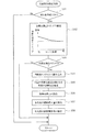
[気筒別空燃比制御ルーチン]
図2に示す気筒別空燃比制御ルーチンは、クランク角センサ33の出力パルスに同期して所定クランク角毎(例えば30℃A毎)に起動され、特許請求の範囲でいう気筒別空燃比制御手段としての役割を果たす。本ルーチンが起動されると、まずステップ101で、気筒別空燃比制御の実行条件が成立しているか否かを判定する。この気筒別空燃比制御の実行条件としては、例えば次の条件(1) 〜(4) がある。
[Air-fuel ratio control routine for each cylinder]
The cylinder-by-cylinder air-fuel ratio control routine shown in FIG. 2 is started at every predetermined crank angle (for example, every 30 ° C. A) in synchronization with the output pulse of the
(1) 空燃比センサ37が活性状態であること
(2) 空燃比センサ37が異常(故障)と判定されていないこと
(3) エンジン11が暖機状態(例えば冷却水温が所定温度以上)であること
(4) エンジン運転領域(例えばエンジン回転速度と吸気管圧力)が空燃比推定精度を確保できる運転領域であること
(1) The air-
(2) The air-
(3) The
(4) The engine operating range (for example, engine speed and intake pipe pressure) must be an operating range where air-fuel ratio estimation accuracy can be ensured.
これら4つの条件(1) 〜(4) を全て満したときに気筒別空燃比制御の実行条件が成立し、いずれか1つでも満たさない条件があれば、実行条件が不成立となる。実行条件が不成立の場合は、以降の処理を行うことなく、本ルーチンを終了する。 The execution condition of the cylinder-by-cylinder air-fuel ratio control is satisfied when all of these four conditions (1) to (4) are satisfied. If any one of the conditions is not satisfied, the execution condition is not satisfied. If the execution condition is not satisfied, this routine is terminated without performing the subsequent processing.
一方、実行条件が成立している場合は、ステップ102に進み、各気筒の空燃比検出タイミング(空燃比センサ37の出力のサンプルタイミング)を、その時点のエンジン負荷(例えば吸気管圧力)に応じてマップにより設定する。尚、各気筒の空燃比検出タイミングをエンジン負荷とエンジン回転速度に応じてマップにより設定しても良い。この空燃比検出タイミングを設定するマップは、後述する図6及び図7の空燃比検出タイミングずれ学習補正ルーチンによって学習補正される。 On the other hand, if the execution condition is satisfied, the routine proceeds to step 102, where the air-fuel ratio detection timing (sample timing of the output of the air-fuel ratio sensor 37) of each cylinder is determined according to the engine load (for example, intake pipe pressure) at that time. Set by map. Note that the air-fuel ratio detection timing of each cylinder may be set by a map according to the engine load and the engine speed. The map for setting the air-fuel ratio detection timing is learned and corrected by an air-fuel ratio detection timing deviation learning correction routine shown in FIGS.
この後、ステップ103に進み、現在のクランク角が上記ステップ102で設定した空燃比検出タイミングであるか否かを判定し、空燃比検出タイミングでなければ、以降の処理を行うことなく、本ルーチンを終了する。
Thereafter, the routine proceeds to step 103, where it is determined whether or not the current crank angle is the air-fuel ratio detection timing set in
これに対して、現在のクランク角が上記ステップ102で設定した空燃比検出タイミングであれば、ステップ104に進み、空燃比センサ37の出力(空燃比検出値)を読み込む。この後、ステップ105に進み、前記気筒別空燃比推定モデルを用いて今回の空燃比推定対象となる気筒の空燃比を空燃比センサ37の検出値に基づいて推定する。このステップ105の処理が特許請求の範囲でいう気筒別空燃比推定手段としての役割を果たす。この後、ステップ106に進み、全気筒の推定空燃比の平均値を算出して、その平均値を基準空燃比(全気筒の目標空燃比)に設定する。
On the other hand, if the current crank angle is the air-fuel ratio detection timing set in
この後、ステップ107に進み、各気筒の推定空燃比と基準空燃比との偏差を算出して、その偏差が小さくなるように各気筒の燃料補正量を算出した後、ステップ108に進み、各気筒の燃料補正量に基づいて各気筒の燃料噴射量を補正することで、各気筒に供給する混合気の空燃比を各気筒毎に補正して気筒間の空燃比ばらつきを少なくするように制御する。 Thereafter, the routine proceeds to step 107, where the deviation between the estimated air-fuel ratio of each cylinder and the reference air-fuel ratio is calculated, the fuel correction amount of each cylinder is calculated so that the deviation becomes smaller, and then the routine proceeds to step 108, where By correcting the fuel injection amount of each cylinder based on the fuel correction amount of the cylinder, the air-fuel ratio of the air-fuel mixture supplied to each cylinder is corrected for each cylinder so that variations in the air-fuel ratio among the cylinders are reduced. To do.
[空燃比検出タイミングずれ判定ルーチン]
まず、空燃比検出タイミングのずれの判定方法を図3及び図4のタイムチャートを用いて説明する。図3は各気筒の空燃比検出タイミングが正しい場合の制御例であり、図4は各気筒の空燃比検出タイミングがずれている場合の制御例である。
[Air-fuel ratio detection timing deviation determination routine]
First, a method for determining the deviation of the air-fuel ratio detection timing will be described with reference to the time charts of FIGS. FIG. 3 is a control example when the air-fuel ratio detection timing of each cylinder is correct, and FIG. 4 is a control example when the air-fuel ratio detection timing of each cylinder is shifted.
図3に示すように、各気筒の空燃比検出タイミングが正しい場合は、空燃比センサ37の検出値に基づいて各気筒の空燃比を精度良く推定できるため、気筒別空燃比制御を開始すると、各気筒の推定空燃比と基準空燃比との偏差(以下この偏差を「推定空燃比偏差」という)が小さくなり、気筒間の推定空燃比のばらつきが小さくなる。
As shown in FIG. 3, when the air-fuel ratio detection timing of each cylinder is correct, the air-fuel ratio of each cylinder can be accurately estimated based on the detection value of the air-
これに対し、図4に示すように、各気筒の空燃比検出タイミングがずれている場合は、空燃比センサ37の検出値から算出する各気筒の推定空燃比の精度が悪化するため、気筒別空燃比制御を続けても各気筒の推定空燃比偏差がいつまでも小さくならならず、気筒間の推定空燃比のばらつきが小さくならない状態となる。
On the other hand, as shown in FIG. 4, when the air-fuel ratio detection timing of each cylinder is shifted, the accuracy of the estimated air-fuel ratio of each cylinder calculated from the detection value of the air-
このような特性に着目し、本実施例1では、図5の空燃比検出タイミングずれ判定ルーチンを実行することで、気筒間の推定空燃比のばらつき度合いが大きいか否かで空燃比検出タイミングのずれの有無を判定するようにしている。本ルーチンは、クランク角センサ33の出力パルスに同期して所定クランク角毎(例えば30℃A毎)に起動される。本ルーチンが起動されると、まずステップ201で、気筒別空燃比制御中であるか否かを判定し、気筒別空燃比制御中でなければ、以降の処理を行うことなく、本ルーチンを終了する。
Focusing on such characteristics, in the first embodiment, by executing the air-fuel ratio detection timing deviation determination routine of FIG. 5, the air-fuel ratio detection timing is determined depending on whether or not the degree of variation in the estimated air-fuel ratio between the cylinders is large. The presence or absence of deviation is determined. This routine is started every predetermined crank angle (for example, every 30 ° C. A) in synchronization with the output pulse of the
これに対して、気筒別空燃比制御中であれば、ステップ202に進み、気筒間の推定空燃比のばらつき度合いが大きいか否かを例えば下記の条件(A1),(A2)のいずれか一方又は両方によって判定する。 On the other hand, if the cylinder-by-cylinder air-fuel ratio control is being performed, the routine proceeds to step 202, where it is determined whether or not the degree of variation in the estimated air-fuel ratio between the cylinders is large, for example, one of the following conditions (A1) and (A2) Or by both.
(A1)各気筒の推定空燃比のうちの最大の推定空燃比と最小の推定空燃比との偏差が所定値以上であるか否かで、気筒間の推定空燃比のばらつき度合いが大きいか否かを判定する。
(A2)全気筒の推定空燃比の標準偏差が所定値以上であるか否かで、気筒間の推定空燃比のばらつき度合いが大きいか否かを判定する。
(A1) Whether the variation in estimated air-fuel ratio between cylinders is large depending on whether the deviation between the maximum estimated air-fuel ratio and the minimum estimated air-fuel ratio among the estimated air-fuel ratios of each cylinder is a predetermined value or more Determine whether.
(A2) It is determined whether or not the degree of variation in the estimated air-fuel ratio among the cylinders is large depending on whether the standard deviation of the estimated air-fuel ratio of all the cylinders is equal to or greater than a predetermined value.
このステップ202で、気筒間の推定空燃比のばらつき度合いが大きいと判定されれば、ステップ203に進み、空燃比検出タイミングがずれていると判定して、本ルーチンを終了する。尚、気筒間の推定空燃比のばらつき度合いが小さい場合(ステップ202で「No」と判定される場合)には、空燃比検出タイミングが正しいと判断して、本ルーチンを終了する。
If it is determined in
[空燃比検出タイミングずれ学習補正ルーチン]
まず、空燃比検出タイミングのずれの学習補正方法を図8及び図9を用いて説明する。図8及び図9は、空燃比検出タイミングが正しい場合とずれている場合の燃料噴射量の補正(燃料補正)の効果を説明する図である。空燃比検出タイミングが正しい場合は、各気筒の空燃比を精度良く推定できるため、所定の気筒の燃料噴射量を所定量補正すると、その気筒の空燃比は、燃料補正量相当分だけ変化するはずである。この特性に着目して、本実施例1では、図6及び図7の空燃比検出タイミングずれ学習補正ルーチンを実行することで、各気筒の空燃比検出タイミングを変化させて、当該空燃比検出タイミングにおける各気筒の燃料補正前後の空燃比を推定し、燃料補正前後の推定空燃比の変化量が燃料補正量相当分になる空燃比検出タイミングを適正な空燃比検出タイミングとして学習するようにしている。
[Air-fuel ratio detection timing deviation learning correction routine]
First, a learning correction method for deviation in the air-fuel ratio detection timing will be described with reference to FIGS. 8 and 9 are diagrams for explaining the effect of fuel injection amount correction (fuel correction) when the air-fuel ratio detection timing is different from the correct timing. When the air-fuel ratio detection timing is correct, the air-fuel ratio of each cylinder can be accurately estimated. Therefore, if the fuel injection amount of a predetermined cylinder is corrected by a predetermined amount, the air-fuel ratio of that cylinder should change by an amount corresponding to the fuel correction amount. It is. Focusing on this characteristic, in the first embodiment, the air-fuel ratio detection timing of each cylinder is changed by executing the air-fuel ratio detection timing deviation learning correction routine of FIG. 6 and FIG. The air-fuel ratio before and after fuel correction of each cylinder is estimated, and the air-fuel ratio detection timing at which the amount of change in the estimated air-fuel ratio before and after fuel correction is equivalent to the fuel correction amount is learned as the appropriate air-fuel ratio detection timing. .
図6及び図7の空燃比検出タイミングずれ学習補正ルーチンは、図5の空燃比検出タイミングずれ判定ルーチンの終了後に起動され、特許請求の範囲でいう学習手段としての役割を果たす。本ルーチンが起動されると、まずステップ301で、図5の空燃比検出タイミングずれ判定ルーチンにより空燃比検出タイミングがずれていると判定されたか否かを判定し、空燃比検出タイミングがずれていると判定されていない場合には、以降の処理を行うことなく、本ルーチンを終了する。
The air-fuel ratio detection timing deviation learning correction routine shown in FIGS. 6 and 7 is started after the air-fuel ratio detection timing deviation determination routine shown in FIG. 5 ends, and serves as learning means in the claims. When this routine is started, first, at
一方、空燃比検出タイミングがずれていると判定されている場合には、ステップ302に進み、遅角補正回数(空燃比検出タイミングを遅角側に補正した回数)が規定回数未満であるか否かを判定し、遅角補正回数が規定回数未満であれば、ステップ303に進み、空燃比検出タイミングを遅角側に所定クランク角だけ補正する。この後、ステップ304に進み、遅角補正後の空燃比検出タイミングにおける当該気筒の燃料補正前後の空燃比を推定し、燃料補正前後の推定空燃比の変化量を算出する。 On the other hand, if it is determined that the air-fuel ratio detection timing is deviated, the process proceeds to step 302, and whether or not the number of delay corrections (the number of times the air-fuel ratio detection timing is corrected to the retard side) is less than the specified number. If the number of delay corrections is less than the specified number, the process proceeds to step 303, and the air-fuel ratio detection timing is corrected to the retard side by a predetermined crank angle. Thereafter, the routine proceeds to step 304, where the air-fuel ratio before and after fuel correction of the cylinder at the air-fuel ratio detection timing after retardation correction is estimated, and the change amount of the estimated air-fuel ratio before and after fuel correction is calculated.
この後、ステップ305に進み、推定空燃比の変化量が燃料補正量相当分にほぼ一致するか否かを判定することで、現在の空燃比検出タイミングが適正な空燃比検出タイミングであるか否かを判定する。その結果、現在の空燃比検出タイミングが適正な空燃比検出タイミングでないと判定された場合には、ステップ302に戻り、上述した空燃比検出タイミングの遅角補正を繰り返す。この遅角補正回数が規定回数に達する前に、推定空燃比の変化量が燃料補正量相当分にほぼ一致して空燃比検出タイミングが適正な空燃比検出タイミングになったと判定されれば、ステップ306に進み、その時点の空燃比検出タイミングを適正な空燃比検出タイミングとして学習し、その学習値をECU40のバックアップRAM等の書き換え可能な不揮発性メモリの学習値記憶領域に更新記憶する。この際、エンジン運転状態に応じて適正な空燃比検出タイミングが変化することを考慮して、図10に示すように、空燃比検出タイミングの学習値をエンジン運転状態(例えばエンジン負荷とエンジン回転速度)毎に更新記憶する。この後、ステップ307に進み、遅角補正回数のカウント値をリセットした本ルーチンを終了する。
Thereafter, the process proceeds to step 305, and it is determined whether or not the change amount of the estimated air-fuel ratio substantially matches the fuel correction amount equivalent, so that whether or not the current air-fuel ratio detection timing is an appropriate air-fuel ratio detection timing. Determine whether. As a result, when it is determined that the current air-fuel ratio detection timing is not an appropriate air-fuel ratio detection timing, the process returns to step 302, and the above-described retardation correction of the air-fuel ratio detection timing is repeated. If it is determined that the amount of change in the estimated air-fuel ratio substantially coincides with the fuel correction amount equivalent and the air-fuel ratio detection timing has reached an appropriate air-fuel ratio detection timing before the number of retardation corrections reaches the specified number, Proceeding to 306, the air-fuel ratio detection timing at that time is learned as an appropriate air-fuel ratio detection timing, and the learned value is updated and stored in a learning value storage area of a rewritable nonvolatile memory such as a backup RAM of the
これに対して、空燃比検出タイミングの遅角補正を規定回数繰り返しても、空燃比検出タイミングが適正な空燃比検出タイミングにならなかった場合には、図7のステップ308に進み、進角補正回数(空燃比検出タイミングを進角側に補正した回数)が規定回数未満であるか否かを判定し、進角補正回数が規定回数未満であれば、ステップ309に進み、空燃比検出タイミングを遅角補正前の最初の位置から進角側に所定クランク角だけ補正する。この後、ステップ310に進み、進角補正後の空燃比検出タイミングにおける当該気筒の燃料補正前後の空燃比を推定し、燃料補正前後の推定空燃比の変化量を算出する。 On the other hand, if the air-fuel ratio detection timing does not reach an appropriate air-fuel ratio detection timing even if the retardation correction of the air-fuel ratio detection timing is repeated a specified number of times, the process proceeds to step 308 in FIG. It is determined whether or not the number of times (the number of times the air-fuel ratio detection timing has been corrected to the advance side) is less than the specified number of times, and if the number of advance angle corrections is less than the specified number of times, the process proceeds to step 309 and the air-fuel ratio detection timing is set. A predetermined crank angle is corrected from the initial position before the retard correction to the advance side. Thereafter, the process proceeds to step 310, where the air-fuel ratio before and after fuel correction of the cylinder at the air-fuel ratio detection timing after advance angle correction is estimated, and the change amount of the estimated air-fuel ratio before and after fuel correction is calculated.
この後、ステップ311に進み、推定空燃比の変化量が燃料補正量相当分にほぼ一致するか否かを判定することで、現在の空燃比検出タイミングが適正な空燃比検出タイミングであるか否かを判定する。その結果、現在の空燃比検出タイミングが適正な空燃比検出タイミングでないと判定された場合には、ステップ308に戻り、上述した空燃比検出タイミングの進角補正を繰り返す。この進角補正回数が規定回数に達する前に、推定空燃比の変化量が燃料補正量相当分にほぼ一致して空燃比検出タイミングが適正な空燃比検出タイミングになったと判定されれば、ステップ312に進み、その時点の空燃比検出タイミングを適正な空燃比検出タイミングとして学習し、その学習値をECU40のバックアップRAM等の書き換え可能な不揮発性メモリに更新記憶する。この後、ステップ313に進み、進角補正回数のカウント値をリセットした本ルーチンを終了する。
Thereafter, the process proceeds to step 311 to determine whether or not the current air-fuel ratio detection timing is an appropriate air-fuel ratio detection timing by determining whether or not the amount of change in the estimated air-fuel ratio substantially matches the fuel correction amount equivalent. Determine whether. As a result, when it is determined that the current air-fuel ratio detection timing is not an appropriate air-fuel ratio detection timing, the process returns to step 308 to repeat the advance correction of the air-fuel ratio detection timing described above. If it is determined that the amount of change in the estimated air-fuel ratio substantially matches the fuel correction amount and the air-fuel ratio detection timing has reached an appropriate air-fuel ratio detection timing before the advance angle correction count reaches the specified number of times, Proceeding to 312, the air-fuel ratio detection timing at that time is learned as an appropriate air-fuel ratio detection timing, and the learned value is updated and stored in a rewritable nonvolatile memory such as a backup RAM of the
本ルーチンにより作成される空燃比検出タイミングの学習マップは、前記図2の気筒別空燃比制御ルーチンのステップ102で、空燃比検出タイミングを設定するマップとして使用される。
The learning map of the air-fuel ratio detection timing created by this routine is used as a map for setting the air-fuel ratio detection timing in
尚、空燃比検出タイミングの進角補正を規定回数繰り返しても、空燃比検出タイミングが適正な空燃比検出タイミングにならなかった場合(つまり適正な空燃比検出タイミングを学習できなかった場合)には、ステップ308で「No」と判定され、本ルーチンを終了する。
If the advance correction of the air-fuel ratio detection timing is repeated a specified number of times, but the air-fuel ratio detection timing does not reach the proper air-fuel ratio detection timing (that is, the proper air-fuel ratio detection timing cannot be learned) In
以上説明した本実施例1では、気筒別空燃比制御中に気筒間の推定空燃比のばらつき度合いに基づいて空燃比検出タイミングのずれの有無を判定するようにしたので、気筒別空燃比制御中に空燃比検出タイミングのずれを精度良く判定することができる。 In the first embodiment described above, the presence / absence of a deviation in the air-fuel ratio detection timing is determined based on the degree of variation in the estimated air-fuel ratio between the cylinders during the cylinder-by-cylinder air-fuel ratio control. In addition, it is possible to accurately determine the deviation of the air-fuel ratio detection timing.
しかも、本実施例1では、気筒別空燃比制御中に各気筒の空燃比検出タイミングを変化させて、当該空燃比検出タイミングにおける各気筒の燃料補正前後の空燃比を推定し、燃料補正前後の推定空燃比の変化量が燃料補正量相当分になる空燃比検出タイミングを適正な空燃比検出タイミングとして学習するようにしたので、気筒別空燃比制御中に適正な空燃比検出タイミングを学習することができ、その学習結果に基づいて各気筒の空燃比検出タイミングを適正な空燃比検出タイミングに補正することができて、各気筒の空燃比を精度良く推定することができる。 Moreover, in the first embodiment, the air-fuel ratio detection timing of each cylinder is changed during the air-fuel ratio control for each cylinder, the air-fuel ratio before and after fuel correction of each cylinder at the air-fuel ratio detection timing is estimated, and before and after fuel correction. Since the air-fuel ratio detection timing at which the change amount of the estimated air-fuel ratio is equivalent to the fuel correction amount is learned as the appropriate air-fuel ratio detection timing, the proper air-fuel ratio detection timing is learned during the cylinder-by-cylinder air-fuel ratio control. The air-fuel ratio detection timing of each cylinder can be corrected to an appropriate air-fuel ratio detection timing based on the learning result, and the air-fuel ratio of each cylinder can be accurately estimated.
更に、本実施例1では、エンジン運転状態に応じて適正な空燃比検出タイミングが変化することを考慮して、空燃比検出タイミングをエンジン運転状態(例えばエンジン負荷とエンジン回転速度)毎に学習するようにしたので、空燃比検出タイミングの学習値の精度を向上させることができる。
しかしながら、本発明は、空燃比検出タイミングの平均的なずれを学習するようにしても良いことは言うまでもない。
Further, in the first embodiment, the air-fuel ratio detection timing is learned for each engine operation state (for example, engine load and engine speed) in consideration of the fact that the appropriate air-fuel ratio detection timing changes according to the engine operation state. Since it did in this way, the precision of the learning value of an air fuel ratio detection timing can be improved.
However, it goes without saying that the present invention may learn the average deviation of the air-fuel ratio detection timing.
図3に示すように、各気筒の空燃比検出タイミングが正しい場合は、空燃比センサ37の検出値に基づいて各気筒の空燃比を精度良く推定できるため、気筒別空燃比制御開始後に各気筒の燃料補正量が増加するにつれて各気筒の推定空燃比と基準空燃比との偏差(推定空燃比偏差)が小さくなり、気筒間の推定空燃比のばらつきが小さくなる。
As shown in FIG. 3, when the air-fuel ratio detection timing of each cylinder is correct, the air-fuel ratio of each cylinder can be accurately estimated based on the detection value of the air-
これに対し、図4に示すように、各気筒の空燃比検出タイミングがずれている場合は、空燃比センサ37の検出値から算出する各気筒の推定空燃比の精度が悪化するため、気筒別空燃比制御開始後に各気筒の燃料補正量が増加しても各気筒の推定空燃比偏差が小さくならならず、気筒間の推定空燃比のばらつきが小さくならない状態となる。
On the other hand, as shown in FIG. 4, when the air-fuel ratio detection timing of each cylinder is shifted, the accuracy of the estimated air-fuel ratio of each cylinder calculated from the detection value of the air-
この特性に着目して、本発明の実施例2では、図11の空燃比検出タイミングずれ判定ルーチンを実行することで、気筒別空燃比制御中に気筒間の燃料補正量のばらつき度合いと気筒間の推定空燃比のばらつき度合いとに基づいて空燃比検出タイミングのずれの有無を判定するようにしている。本ルーチンは、クランク角センサ33の出力パルスに同期して所定クランク角毎(例えば30℃A毎)に起動される。本ルーチンが起動されると、まずステップ401で、気筒別空燃比制御中であるか否かを判定し、気筒別空燃比制御中でなければ、以降の処理を行うことなく、本ルーチンを終了する。
Focusing on this characteristic, in the second embodiment of the present invention, by executing the air-fuel ratio detection timing deviation determination routine of FIG. Whether or not there is a deviation in the air-fuel ratio detection timing is determined based on the degree of variation in the estimated air-fuel ratio. This routine is started every predetermined crank angle (for example, every 30 ° C. A) in synchronization with the output pulse of the
これに対して、気筒別空燃比制御中であれば、ステップ402に進み、所定以上の燃料補正を実施中であるか否かを例えば下記の条件(B1)〜(B3)のいずれか1つ又は2つ以上によって判定する。 On the other hand, if the cylinder-by-cylinder air-fuel ratio control is being performed, the routine proceeds to step 402, where it is determined whether or not fuel correction of a predetermined level or more is being performed, for example, one of the following conditions (B1) to (B3): Or it judges by two or more.
(B1)各気筒の燃料補正量のうちの最大の燃料補正量と最小の燃料補正量との偏差が所定値以上であるか否かで、所定以上の燃料補正を実施中であるか否かを判定する。
(B2)全気筒の燃料補正量の標準偏差が所定値以上であるか否かで、所定以上の燃料補正を実施中であるか否かを判定する。
(B3)燃料補正開始後の経過時間が所定時間以上であるか否かで、所定以上の燃料補正を実施中であるか否かを判定する。
(B1) Whether or not fuel correction more than a predetermined value is being performed depending on whether or not the deviation between the maximum fuel correction value and the minimum fuel correction value among the fuel correction values for each cylinder is equal to or greater than a predetermined value Determine.
(B2) It is determined whether or not fuel correction greater than or equal to a predetermined value is being performed based on whether or not the standard deviation of fuel correction amounts for all cylinders is greater than or equal to a predetermined value.
(B3) It is determined whether or not fuel correction greater than or equal to a predetermined value is being performed based on whether or not the elapsed time after the start of fuel correction is greater than or equal to a predetermined time.
このステップ402で、所定以上の燃料補正を実施していないと判定されれば、そのまま本ルーチンを終了するが、所定以上の燃料補正を実施中であると判定されれば、ステップ403に進み、気筒間の推定空燃比のばらつき度合いが大きいか否かを例えば下記の条件(C1),(C2)のいずれか一方又は両方によって判定する。
If it is determined in
(C1)各気筒の推定空燃比のうちの最大の推定空燃比と最小の推定空燃比との偏差が所定値以上であるか否かで、気筒間の推定空燃比のばらつき度合いが大きいか否かを判定する。
(C2)全気筒の推定空燃比の標準偏差が所定値以上であるか否かで、気筒間の推定空燃比のばらつき度合いが大きいか否かを判定する。
(C1) Whether the variation in estimated air-fuel ratio between cylinders is large depending on whether the deviation between the maximum estimated air-fuel ratio and the minimum estimated air-fuel ratio among the estimated air-fuel ratios of each cylinder is a predetermined value or more Determine whether.
(C2) It is determined whether or not the degree of variation in the estimated air-fuel ratio among the cylinders is large depending on whether the standard deviation of the estimated air-fuel ratio of all the cylinders is equal to or greater than a predetermined value.
このステップ403で、気筒間の推定空燃比のばらつき度合いが大きいと判定されれば、ステップ404に進み、空燃比検出タイミングがずれていると判定して、本ルーチンを終了する。尚、気筒間の推定空燃比のばらつき度合いが小さい場合(ステップ403で「No」と判定される場合)には、空燃比検出タイミングが正しいと判断して、本ルーチンを終了する。
If it is determined in
以上説明した本実施例2においても、気筒別空燃比制御中に空燃比検出タイミングのずれを精度良く判定することができる。 Also in the second embodiment described above, it is possible to accurately determine the deviation of the air-fuel ratio detection timing during the cylinder-by-cylinder air-fuel ratio control.
各気筒の推定空燃比の精度が良ければ、各気筒の燃料補正量の増減方向と推定空燃比の増減方向とが同じ挙動になる運転状態において、これと反対の挙動になれば、各気筒の推定空燃比の精度が悪いと考えられる。 If the accuracy of the estimated air-fuel ratio of each cylinder is good, in the operating state where the increase / decrease direction of the fuel correction amount of each cylinder and the increase / decrease direction of the estimated air-fuel ratio are the same behavior, It is considered that the accuracy of the estimated air-fuel ratio is poor.
この特性に着目して、本発明の実施例3では、図12の空燃比検出タイミングずれ判定ルーチンを実行することで、気筒別空燃比制御中に各気筒の燃料補正量の増減方向と推定空燃比の増減方向とに基づいて空燃比検出タイミングのずれの有無を判定するようにしている。本ルーチンは、クランク角センサ33の出力パルスに同期して所定クランク角毎(例えば30℃A毎)に起動される。本ルーチンが起動されると、まずステップ501で、気筒別空燃比制御中であるか否かを判定し、気筒別空燃比制御中でなければ、以降の処理を行うことなく、本ルーチンを終了する。
Focusing on this characteristic, in the third embodiment of the present invention, by executing the air-fuel ratio detection timing deviation determination routine of FIG. 12, during the cylinder-by-cylinder air-fuel ratio control, the fuel correction amount increase / decrease direction of each cylinder and the estimated sky The presence or absence of a deviation in the air-fuel ratio detection timing is determined based on the increase / decrease direction of the fuel ratio. This routine is started every predetermined crank angle (for example, every 30 ° C. A) in synchronization with the output pulse of the
これに対して、気筒別空燃比制御中であれば、ステップ502に進み、所定以上の燃料補正を実施中であるか否かを例えば下記の条件(D1), (D3)のいずれか一方又は両方によって判定する。 On the other hand, if the cylinder-by-cylinder air-fuel ratio control is being performed, the routine proceeds to step 502, where it is determined whether or not fuel correction of a predetermined value or more is being performed, for example, either one of the following conditions (D1), (D3) or Judge by both.
(D1)各気筒の燃料補正量のうちの最大の燃料補正量と最小の燃料補正量との偏差が所定値以上であるか否かで、所定以上の燃料補正を実施中であるか否かを判定する。
(D2)特定気筒の燃料補正量が所定値以上であるか否かで、所定以上の燃料補正を実施中であるか否かを判定する。
(D1) Whether or not fuel correction more than a predetermined value is being performed depending on whether or not the deviation between the maximum fuel correction value and the minimum fuel correction value among the fuel correction values for each cylinder is equal to or greater than a predetermined value Determine.
(D2) It is determined whether or not fuel correction greater than a predetermined value is being performed based on whether or not the fuel correction amount of the specific cylinder is greater than or equal to a predetermined value.
このステップ502で、所定以上の燃料補正を実施していないと判定されれば、そのまま本ルーチンを終了するが、所定以上の燃料補正を実施中であると判定されれば、ステップ503に進み、各気筒の燃料補正量の増減方向と推定空燃比の増減方向とが反対の挙動になっているか否かを、例えば各気筒の燃料補正量の変化率と推定空燃比の変化率との偏差が所定値以上であるか否かによって判定する。その結果、各気筒の燃料補正量の増減方向と推定空燃比の増減方向とが反対の挙動になっていると判定されれば、ステップ504に進み、空燃比検出タイミングがずれていると判定して、本ルーチンを終了する。尚、各気筒の燃料補正量の増減方向と推定空燃比の増減方向とが同じ挙動になっている場合(ステップ503で「No」と判定される場合)には、空燃比検出タイミングが正しいと判断して、本ルーチンを終了する。
If it is determined in
以上説明した本実施例3においても、気筒別空燃比制御中に空燃比検出タイミングのずれを精度良く判定することができる。 Also in the third embodiment described above, it is possible to accurately determine the deviation in the air-fuel ratio detection timing during the cylinder-by-cylinder air-fuel ratio control.
各気筒の空燃比検出タイミングが正しければ、空燃比センサ37の検出値に基づいて各気筒の空燃比を精度良く推定できるため、図13に示すように、空燃比検出タイミングの最適点において、気筒間の推定空燃比のばらつき度合い(各気筒の推定空燃比偏差)が最小になると共に、気筒間の燃料補正量のばらつき度合いも最小になる。
If the air-fuel ratio detection timing of each cylinder is correct, the air-fuel ratio of each cylinder can be accurately estimated based on the detection value of the air-
この特性に着目して、本発明の実施例4では、図14に示す空燃比検出タイミングずれ学習補正ルーチンを実行することで、気筒別空燃比制御中に各気筒の空燃比検出タイミングを変化させて各気筒の空燃比を推定し、気筒間の推定空燃比のばらつき度合い及び燃料補正量のばらつき度合いが最小となる空燃比検出タイミングを適正な空燃比検出タイミングとして学習するようにしている。 Focusing on this characteristic, the fourth embodiment of the present invention changes the air-fuel ratio detection timing of each cylinder during the air-fuel ratio control for each cylinder by executing the air-fuel ratio detection timing deviation learning correction routine shown in FIG. Thus, the air-fuel ratio of each cylinder is estimated, and the air-fuel ratio detection timing at which the degree of variation in estimated air-fuel ratio between cylinders and the degree of variation in fuel correction amount are minimized is learned as an appropriate air-fuel ratio detection timing.
本ルーチンは、実施例1〜3のいずれかで説明した空燃比検出タイミングずれ判定ルーチンによって空燃比検出タイミングのずれの有無を判定した後に起動され、特許請求の範囲でいう学習手段としての役割を果たす。本ルーチンが起動されると、まずステップ601で、空燃比検出タイミングずれ判定ルーチンにより空燃比検出タイミングがずれていると判定されたか否かを判定し、空燃比検出タイミングがずれていると判定されていない場合には、以降の処理を行うことなく、本ルーチンを終了する。
This routine is started after the presence or absence of a deviation in the air-fuel ratio detection timing is determined by the air-fuel ratio detection timing deviation determination routine described in any of the first to third embodiments, and serves as a learning means in the claims. Fulfill. When this routine is started, first, at
一方、空燃比検出タイミングがずれていると判定されている場合には、ステップ602に進み、空燃比検出タイミングを最進角位置(補正可能な進角側の限界位置)に設定する。この後、ステップ603に進み、気筒間の推定空燃比のばらつき度合いを下記(E1),(E2)のいずれかによって算出する。 On the other hand, if it is determined that the air-fuel ratio detection timing is deviated, the process proceeds to step 602, where the air-fuel ratio detection timing is set to the most advanced angle position (correctable advance side limit position). Thereafter, the process proceeds to step 603, where the degree of variation in the estimated air-fuel ratio between the cylinders is calculated by either (E1) or (E2) below.
(E1)各気筒の推定空燃比のうちの最大の推定空燃比と最小の推定空燃比との偏差を算出して、これを気筒間の推定空燃比のばらつき度合いとする。
(E2)全気筒の推定空燃比の標準偏差を算出して、これを気筒間の推定空燃比のばらつき度合いとする。
(E1) The deviation between the maximum estimated air-fuel ratio and the minimum estimated air-fuel ratio among the estimated air-fuel ratios of each cylinder is calculated, and this is used as the degree of variation in estimated air-fuel ratio between cylinders.
(E2) The standard deviation of the estimated air-fuel ratio of all cylinders is calculated, and this is used as the degree of variation in the estimated air-fuel ratio between the cylinders.
この後、ステップ604に進み、気筒間の燃料補正量のばらつき度合いを下記(F1),(F2)のいずれかによって算出する。
(F1)各気筒の燃料補正量のうちの最大の燃料補正量と最小の燃料補正量との偏差を算出して、これを気筒間の燃料補正量のばらつき度合いとする。
(F2)全気筒の燃料補正量の標準偏差を算出して、これを気筒間の燃料補正量のばらつき度合いとする。
Thereafter, the process proceeds to step 604, and the degree of variation in the fuel correction amount between the cylinders is calculated by either (F1) or (F2) below.
(F1) A deviation between the maximum fuel correction amount and the minimum fuel correction amount among the fuel correction amounts of the respective cylinders is calculated, and this is set as a variation degree of the fuel correction amount between the cylinders.
(F2) The standard deviation of the fuel correction amount of all cylinders is calculated, and this is used as the degree of variation in the fuel correction amount between the cylinders.
この後、ステップ604に進み、空燃比検出タイミングを遅角側に所定クランク角だけ補正した後、ステップ605に進み、遅角補正後の空燃比検出タイミングが最遅角位置(補正可能な遅角側の限界位置)を越えたか否かを判定し、越えていなければ、ステップ603に戻り、上述した処理を繰り返す。これにより、空燃比検出タイミングを最進角位置から最遅角位置に向けて少しずつ進角させて気筒間の推定空燃比のばらつき度合いと燃料補正量のばらつき度合いを算出する処理を繰り返す。 Thereafter, the process proceeds to step 604, the air-fuel ratio detection timing is corrected to the retard side by a predetermined crank angle, and then the process proceeds to step 605, where the air-fuel ratio detection timing after the delay angle correction is the most retarded position (correctable retard angle). It is determined whether or not the limit position on the side has been exceeded. If not, the process returns to step 603 to repeat the above-described processing. Thus, the process of calculating the degree of variation in the estimated air-fuel ratio between the cylinders and the degree of variation in the fuel correction amount by advancing the air-fuel ratio detection timing little by little from the most advanced position to the most retarded position is repeated.
その後、ステップ605で遅角補正した空燃比検出タイミングが最遅角位置を越えると、ステップ606の判定結果が「Yes」となって、ステップ607に進み、それまでに算出した気筒間の推定空燃比のばらつき度合いと燃料補正量のばらつき度合いの中からそれらが最小となる空燃比検出タイミングの最適点を検索し、次のステップ608で、この空燃比検出タイミングの最適点をECU40のバックアップRAM等の書き換え可能な不揮発性メモリの学習値記憶領域に更新記憶する。この際、エンジン運転状態に応じて適正な空燃比検出タイミングが変化することを考慮して、空燃比検出タイミングの最適点の学習値をエンジン運転状態(例えばエンジン負荷とエンジン回転速度)毎に更新記憶するようにすると良い。
After that, when the air-fuel ratio detection timing corrected in
以上説明した本実施例4では、気筒別空燃比制御中に空燃比検出タイミングの最適点を精度良く学習することができる。
尚、本実施例4では、空燃比検出タイミングを最進角位置から最遅角位置まで変化させるようにしたが、気筒間の推定空燃比のばらつき度合いと燃料補正量のばらつき度合いが所定値以下になった段階で、これらのばらつき度合いを算出する処理を終了し、これらのばらつき度合いが所定値以下になった位置を適正な空燃比検出タイミングとして学習するようにしても良い。
In the fourth embodiment described above, the optimum point of the air-fuel ratio detection timing can be learned with high accuracy during the cylinder-by-cylinder air-fuel ratio control.
In the fourth embodiment, the air-fuel ratio detection timing is changed from the most advanced position to the most retarded position, but the degree of variation in estimated air-fuel ratio between cylinders and the degree of variation in fuel correction amount are below a predetermined value. At this stage, the process of calculating the degree of variation may be terminated, and the position where the degree of variation becomes a predetermined value or less may be learned as an appropriate air-fuel ratio detection timing.
図15に示すように、燃料カット復帰時に最初に空燃比センサ37の出力が噴射再開後の空燃比に相当するレベルに変化するタイミングは、燃料カット復帰時の最初の噴射気筒のみによって決まり、他の気筒の影響を受けない。
As shown in FIG. 15, the timing at which the output of the air-
この特性に着目して、本発明の実施例5では、図16に示す空燃比検出タイミングずれ学習補正ルーチンを実行することで、燃料カット復帰時に最初に空燃比センサ37の出力が噴射再開後の空燃比に相当する所定レベルに変化するタイミングに基づいて燃料カット復帰時の最初の噴射気筒(以下「燃料カット復帰気筒」という)における適正な空燃比検出タイミングを学習するようにしている。 Focusing on this characteristic, in the fifth embodiment of the present invention, by executing the air-fuel ratio detection timing deviation learning correction routine shown in FIG. An appropriate air-fuel ratio detection timing in the first injection cylinder at the time of fuel cut return (hereinafter referred to as “fuel cut return cylinder”) is learned based on the timing at which the air-fuel ratio changes to a predetermined level.
本ルーチンは、クランク角センサ33の出力パルスに同期して所定クランク角毎(例えば30℃A毎)に起動され、特許請求の範囲でいう学習手段としての役割を果たす。本ルーチンが起動されると、まずステップ701で、燃料カット復帰(燃料カット終了)から所定期間内であるか否かを判定し、所定期間内でなければ、以降の学習処理を行うことなく、本ルーチンを終了する。この所定期間は、燃料カット復帰時に最初に空燃比センサ37の出力が噴射再開後の空燃比に相当する所定レベルに変化するまでの期間よりも少し長い期間に設定されている。尚、この所定期間内にエンジン運転条件(エンジン回転速度や負荷等)の変化量が所定値以上になった場合も、以降の学習処理を行うことなく、本ルーチンを終了するようにしても良い。エンジン運転条件の変化が大きいと、学習精度が低下するためである。
This routine is started at every predetermined crank angle (for example, every 30 ° C. A) in synchronization with the output pulse of the
一方、燃料カット復帰から所定期間内であれば、ステップ702に進み、燃料カット復帰気筒をECU40のRAM等のメモリに記憶した後、ステップ703に進み、空燃比センサ37の出力が噴射再開後の空燃比に相当する所定レベルに変化するまで待機する。この所定レベルは、エンジン運転条件(エンジン回転速度、負荷、燃料補正量等)に応じてマップ等により可変設定するようにしても良い。
On the other hand, if it is within a predetermined period from the fuel cut return, the process proceeds to step 702, the fuel cut return cylinder is stored in a memory such as the RAM of the
その後、空燃比センサ37の出力が噴射再開後の空燃比に相当する所定レベルに変化した時点で、ステップ704に進み、空燃比センサ37の出力が噴射再開後の空燃比に相当する所定レベルに変化した時のクランク角(クランクカウンタの値)と燃料カット復帰気筒の噴射再開時のクランク角(クランクカウンタの値)とのずれ量に基づいて燃料カット復帰気筒の適正な空燃比検出タイミングを算出する。この際、エンジン運転条件(エンジン回転速度、負荷等)を考慮するようにしても良い。
Thereafter, when the output of the air-
この後、ステップ705に進み、この空燃比検出タイミングをECU40のバックアップRAM等の書き換え可能な不揮発性メモリの学習値記憶領域に更新記憶する。この際、エンジン運転状態に応じて適正な空燃比検出タイミングが変化することを考慮して、空燃比検出タイミングの学習値をエンジン運転状態(例えばエンジン負荷とエンジン回転速度)毎に更新記憶するようにすると良い。
Thereafter, the process proceeds to step 705, and the air-fuel ratio detection timing is updated and stored in a learning value storage area of a rewritable nonvolatile memory such as a backup RAM of the
以上説明した本実施例5においても、気筒別空燃比制御中に空燃比検出タイミングの最適点を精度良く学習することができる。
また、特定気筒で検出された空燃比検出タイミングのずれは、他の気筒の空燃比検出タイミングの平均的なずれとして学習するようにしても良いことは言うまでもない。
Also in the fifth embodiment described above, the optimum point of the air-fuel ratio detection timing can be learned with high accuracy during the cylinder-by-cylinder air-fuel ratio control.
Needless to say, the deviation in the air-fuel ratio detection timing detected in the specific cylinder may be learned as the average deviation in the air-fuel ratio detection timing of the other cylinders.
次に、図17乃至図23を用いて本発明の実施例6を説明する。
本実施例6では、空燃比検出タイミングのずれを評価するデータとして、少なくとも1つの気筒の推定空燃比の変化量とその気筒の燃料補正量(空燃比補正量)の変化量との関係を表す指標となる相関値を用いる。
Next,
In the sixth embodiment, as data for evaluating the deviation of the air-fuel ratio detection timing, the relationship between the change amount of the estimated air-fuel ratio of at least one cylinder and the change amount of the fuel correction amount (air-fuel ratio correction amount) of that cylinder is expressed. A correlation value as an index is used.
この相関値は、1つの気筒の推定空燃比の変化量とその気筒の燃料補正量の変化量との積、又はこの積の複数気筒分の和で表される。本実施例6では、各気筒の推定空燃比の変化量と燃料補正量の変化量との積を全気筒数分積算して相関値を求めるようにしている。 This correlation value is represented by the product of the change amount of the estimated air-fuel ratio of one cylinder and the change amount of the fuel correction amount of that cylinder, or the sum of this product for a plurality of cylinders. In the sixth embodiment, the product of the change amount of the estimated air-fuel ratio of each cylinder and the change amount of the fuel correction amount is integrated by the number of all cylinders to obtain the correlation value.
更に、本実施例6では、相関値の算出タイミングを、720℃A当たり複数のタイミング、例えば6つのタイミング(ベースタイミング、ベースタイミング+180℃A、ベースタイミング−180℃A、ベースタイミング+360℃A、ベースタイミング+90℃A、ベースタイミング−90℃A)に設定し、各タイミングで算出した相関値の中で、最も相関値が大きいタイミングを最もずれの少ない空燃比検出タイミングであると判断するようにしている。 Further, in the sixth embodiment, the correlation value is calculated at a plurality of timings per 720 ° C., for example, six timings (base timing, base timing + 180 ° C., base timing −180 ° C. A, base timing + 360 ° C. A, Base timing + 90 ° C., base timing −90 ° C.), among the correlation values calculated at each timing, it is determined that the timing with the largest correlation value is the air-fuel ratio detection timing with the least deviation. ing.
前記実施例3で説明したように、各気筒の燃料補正量の増減方向と推定空燃比の増減方向とが反対の挙動になれば、各気筒の推定空燃比の精度が悪いと考えられる。各気筒の燃料補正量の増減方向と推定空燃比の増減方向とが反対の挙動になれば、各気筒の推定空燃比の変化量の符号(±)と燃料補正量の変化量の符号(±)が反対になるため、両者の積がマイナス値になり、この積の全気筒数分の和である相関値が小さくなる。従って、相関値が小さくなるほど、空燃比検出タイミングのずれが大きいことを意味し、相関値が大きくなるほど、空燃比検出タイミングのずれが小さいことを意味する。この関係から、本実施例6では、相関値を720℃A当たり複数のタイミングで算出して、最も相関値が大きいタイミングを最もずれの少ない空燃比検出タイミングであると判断して、空燃比検出タイミングを学習補正するようにしている。 As described in the third embodiment, if the increase / decrease direction of the fuel correction amount of each cylinder and the increase / decrease direction of the estimated air-fuel ratio are opposite, it is considered that the accuracy of the estimated air-fuel ratio of each cylinder is poor. If the increase / decrease direction of the fuel correction amount of each cylinder and the increase / decrease direction of the estimated air-fuel ratio are opposite, the sign of the change amount of the estimated air-fuel ratio of each cylinder (±) and the sign of the change amount of the fuel correction amount (± ) Is opposite, the product of both becomes a negative value, and the correlation value which is the sum of the number of cylinders of this product becomes smaller. Therefore, the smaller the correlation value, the larger the deviation of the air-fuel ratio detection timing, and the larger the correlation value, the smaller the deviation of the air-fuel ratio detection timing. From this relationship, in the sixth embodiment, the correlation value is calculated at a plurality of timings per 720 ° C., and the timing with the largest correlation value is determined as the air-fuel ratio detection timing with the least deviation, and the air-fuel ratio detection is performed. The timing is corrected by learning.
以上説明した本実施例6の空燃比検出タイミングのずれ判定・学習補正は、ECU40によって図17乃至図22に従って実行される。以下、これら各ルーチンの処理内容を説明する。
The deviation determination / learning correction of the air-fuel ratio detection timing of the sixth embodiment described above is executed by the
図17の空燃比検出タイミングずれ判定ルーチンは、クランク角センサ33の出力パルスに同期して所定クランク角毎(例えば30℃A毎)に起動される。本ルーチンが起動されると、まずステップ801で、気筒別空燃比制御中であるか否かを判定し、気筒別空燃比制御中でなければ、以降の処理を行うことなく、本ルーチンを終了する。
The air-fuel ratio detection timing deviation determination routine of FIG. 17 is started at every predetermined crank angle (for example, every 30 ° C. A) in synchronization with the output pulse of the
これに対して、気筒別空燃比制御中であれば、ステップ802に進み、所定以上の燃料補正を実施中であるか否かを、前記実施例3で説明した図12のステップ502と同様の方法で判定する。このステップ802で、所定以上の燃料補正を実施していないと判定されれば、そのまま本ルーチンを終了するが、所定以上の燃料補正を実施中であると判定されれば、ステップ803に進み、図18の相関値算出ルーチンを実行する。
On the other hand, if the cylinder-by-cylinder air-fuel ratio control is in progress, the routine proceeds to step 802, where whether or not fuel correction of a predetermined value or more is being performed is the same as in
図18の相関値算出ルーチンが起動されると、まずステップ811で、相関値算出タイミング(例えば720℃A毎)であるか否かを判定し、相関値算出タイミングでなければ、以降の処理を行うことなく、本ルーチンを終了する。
When the correlation value calculation routine of FIG. 18 is started, it is first determined in
これに対して、相関値算出タイミングであれば、ステップ812に進み、各気筒の燃料補正係数(燃料補正量)の変化量である差分ΔFAF(1) 〜ΔFAF(N) を算出する。
ΔFAF(k) =ΔFAF(k)[i]−ΔFAF(k)[i-1]
ここで、ΔFAF(k) はk番気筒のΔFAFであり(k=1〜N)、ΔFAF(k)[i]は今回のΔFAF(k) 、ΔFAF(k)[i-1]は前回のΔFAF(k) である。
On the other hand, if it is the correlation value calculation timing, the routine proceeds to step 812, where differences ΔFAF (1) to ΔFAF (N), which are changes in the fuel correction coefficient (fuel correction amount) of each cylinder, are calculated.
ΔFAF (k) = ΔFAF (k) [i] −ΔFAF (k) [i−1]
Here, ΔFAF (k) is ΔFAF of the k-th cylinder (k = 1 to N), ΔFAF (k) [i] is current ΔFAF (k), and ΔFAF (k) [i-1] is the previous time ΔFAF (k).
この後、ステップ813に進み、図19の推定空燃比差分算出ルーチンを実行して、下記の各タイミング(T1)〜(T6)における各気筒の推定空燃比の変化量である差分ΔPHIを算出する。 Thereafter, the routine proceeds to step 813, where the estimated air-fuel ratio difference calculation routine of FIG. 19 is executed to calculate the difference ΔPHI which is the change amount of the estimated air-fuel ratio of each cylinder at the following timings (T1) to (T6). .
(T1)ベースタイミングにおける各気筒の推定空燃比の差分ΔPHIbase
ΔPHIbase(k) =PHIbase(k)[i]−PHIbase(k)[i-1] (k=1〜N)
PHIbase(k) はベースタイミングで推定したk番気筒の推定空燃比である。ベースタイミングは、基準となる空燃比検出タイミングであり、後述する図22の空燃比検出タイミングずれ学習補正ルーチンによって学習補正される。
(T1) Estimated air-fuel ratio difference ΔPHIbase of each cylinder at base timing
ΔPHIbase (k) = PHIbase (k) [i] −PHIbase (k) [i−1] (k = 1 to N)
PHIbase (k) is an estimated air-fuel ratio of the k-th cylinder estimated at the base timing. The base timing is a reference air-fuel ratio detection timing, and is learned and corrected by an air-fuel ratio detection timing deviation learning correction routine shown in FIG.
(T2)ベースタイミング+180℃Aにおける各気筒の推定空燃比の差分ΔPHIp180
ΔPHIp180(k) =PHIp180(k)[i]−PHIp180(k)[i-1] (k=1〜N)
PHIp180(k) はベースタイミング+180℃Aのタイミングで推定したk番気筒の推定空燃比である。
(T2) Estimated air-fuel ratio difference ΔPHIp180 of each cylinder at base timing + 180 ° C.
ΔPHIp180 (k) = PHIp180 (k) [i] −PHIp180 (k) [i−1] (k = 1 to N)
PHIp180 (k) is the estimated air-fuel ratio of the k-th cylinder estimated at the timing of base timing + 180 ° C.
(T3)ベースタイミング−180℃Aにおける各気筒の推定空燃比の差分ΔPHIm180
ΔPHIm180(k) =PHIm180(k)[i]−PHIm180(k)[i-1] (k=1〜N)
PHIm180(k) はベースタイミング−180℃Aのタイミングで推定したk番気筒の推定空燃比である。
(T3) Base timing-difference ΔPHIm180 of estimated air-fuel ratio of each cylinder at 180 ° C A
ΔPHIm180 (k) = PHIm180 (k) [i] −PHIm180 (k) [i−1] (k = 1 to N)
PHIm180 (k) is an estimated air-fuel ratio of the k-th cylinder estimated at a timing of base timing −180 ° C.
(T4)ベースタイミング+360℃Aにおける各気筒の推定空燃比の差分ΔPHIp360
ΔPHIp360(k) =PHIp360(k)[i]−PHIp360(k)[i-1] (k=1〜N)
PHIp360(k) はベースタイミング+360℃Aのタイミングで推定したk番気筒の推定空燃比である。
(T4) Difference in estimated air-fuel ratio of each cylinder at base timing + 360 ° C. ΔPHIp360
ΔPHIp360 (k) = PHIp360 (k) [i] −PHIp360 (k) [i−1] (k = 1 to N)
PHIp360 (k) is an estimated air-fuel ratio of the k-th cylinder estimated at a timing of base timing + 360 ° C.
(T5)ベースタイミング+90℃Aにおける各気筒の推定空燃比の差分ΔPHIp90
ΔPHIp90(k)=PHIp90(k)[i] −PHIp90(k)[i-1] (k=1〜N)
PHIp90(k)はベースタイミング+90℃Aのタイミングで推定したk番気筒の推定空燃比である。
(T5) Estimated air-fuel ratio difference ΔPHIp90 of each cylinder at base timing + 90 ° C.
ΔPHIp90 (k) = PHIp90 (k) [i] −PHIp90 (k) [i−1] (k = 1 to N)
PHIp90 (k) is an estimated air-fuel ratio of the k-th cylinder estimated at the timing of base timing + 90 ° C.
(T6)ベースタイミング−90℃Aにおける各気筒の推定空燃比の差分ΔPHIm90
ΔPHIm90(k)=PHIm90(k)[i] −PHIm90(k)[i-1] (k=1〜N)
PHIm90(k)はベースタイミング−90℃Aのタイミングで推定したk番気筒の推定空燃比である。
(T6) Base timing -difference ΔPHIm90 in estimated air-fuel ratio of each cylinder at 90 ° C. A
ΔPHIm90 (k) = PHIm90 (k) [i] −PHIm90 (k) [i−1] (k = 1 to N)
PHIm90 (k) is an estimated air-fuel ratio of the k-th cylinder estimated at a base timing of −90 ° C.
ここで、各タイミング(T1)〜(T6)におけるk番気筒の推定空燃比PHIbase(k) 〜PHIm90(k)は、当量比φで算出される。
当量比φ=理論空燃比/推定空燃比=1/空気過剰率
Here, the estimated air-fuel ratios PHIbase (k) to PHIm90 (k) of the k-th cylinder at the respective timings (T1) to (T6) are calculated by the equivalence ratio φ.
Equivalent ratio φ = theoretical air / fuel ratio / estimated air / fuel ratio = 1 / excess air ratio
各タイミング(T1)〜(T6)における各気筒の推定空燃比の差分ΔPHIを算出した後、図18のステップ814に進み、図20の瞬時相関値算出ルーチンを実行して、各タイミング(T1)〜(T6)における瞬時相関値dCORを算出する。 After calculating the difference ΔPHI of the estimated air-fuel ratio of each cylinder at each timing (T1) to (T6), the process proceeds to step 814 in FIG. 18, and the instantaneous correlation value calculation routine in FIG. 20 is executed to execute each timing (T1). The instantaneous correlation value dCOR in (T6) is calculated.
(T1)ベースタイミングにおける瞬時相関値dCORbase
dCORbase=Σ{ΔFAF(k) ×ΔPHIbase(k) } (k=1〜N)
ここで、Σは1番気筒からN番気筒まで積算することを意味する(以下、同じ)。
(T2)ベースタイミング+180℃Aにおける瞬時相関値dCORp180
dCORp180=Σ{ΔFAF(k) ×ΔPHIp180(k) } (k=1〜N)
(T3)ベースタイミング−180℃Aにおける瞬時相関値dCORm180
dCORm180=Σ{ΔFAF(k) ×ΔPHIm180(k) } (k=1〜N)
(T4)ベースタイミング+360℃Aにおける瞬時相関値dCORp360
dCORp360=Σ{ΔFAF(k) ×ΔPHIp360(k) } (k=1〜N)
(T5)ベースタイミング+90℃Aにおける瞬時相関値dCORp90
dCORp90 =Σ{ΔFAF(k) ×ΔPHIp90(k)} (k=1〜N)
(T6)ベースタイミング−90℃Aにおける瞬時相関値dCORm90
dCORm90 =Σ{ΔFAF(k) ×ΔPHIm90(k)} (k=1〜N)
(T1) Instantaneous correlation value dCORbase at base timing
dCORbase = Σ {ΔFAF (k) × ΔPHIbase (k)} (k = 1 to N)
Here, Σ means integration from the first cylinder to the Nth cylinder (hereinafter the same).
(T2) Instantaneous correlation value dCORp180 at base timing + 180 ° C A
dCORp180 = Σ {ΔFAF (k) × ΔPHIp180 (k)} (k = 1 to N)
(T3) Base timing-instantaneous correlation value dCORm180 at 180 ° C A
dCORm180 = Σ {ΔFAF (k) × ΔPHIm180 (k)} (k = 1 to N)
(T4) Base timing + instantaneous correlation value dCORp360 at 360 ° C A
dCORp360 = Σ {ΔFAF (k) × ΔPHIp360 (k)} (k = 1 to N)
(T5) Instantaneous correlation value dCORp90 at base timing + 90 ° C A
dCORp90 = Σ {ΔFAF (k) × ΔPHIp90 (k)} (k = 1 to N)
(T6) Base timing-instantaneous correlation value dCORm90 at 90 ° C A
dCORm90 = Σ {ΔFAF (k) × ΔPHIm90 (k)} (k = 1 to N)
各タイミング(T1)〜(T6)における瞬時相関値dCORを算出した後、図18のステップ815に進み、図21の積算相関値算出ルーチンを実行して、各タイミング(T1)〜(T6)における積算相関値sumCORを算出する。 After calculating the instantaneous correlation value dCOR at each timing (T1) to (T6), the process proceeds to step 815 in FIG. 18, and the integrated correlation value calculation routine in FIG. 21 is executed, and at each timing (T1) to (T6). The integrated correlation value sumCOR is calculated.
(T1)ベースタイミングにおける積算相関値sumCORbase(i)
sumCORbase(i) =sumCORbase(i-1) +dCORbase
(sumCORbase(i-1) :前回のsumCORbase)
(T2)ベースタイミング+180℃Aにおける積算相関値sumCORp180(i)
sumCORp180(i) =sumCORp180(i-1) +dCORp180
(sumCORp180(i-1) :前回のsumCORp180)
(T3)ベースタイミング−180℃Aにおける積算相関値sumCORm180(i)
sumCORm180(i) =sumCORm180(i-1) +dCORm180
(sumCORm180(i-1) :前回のsumCORm180)
(T4)ベースタイミング+360℃Aにおける積算相関値sumCORp360(i)
sumCORp360(i) =sumCORp360(i-1) +dCORp360
(sumCORp360(i-1) :前回のsumCORp360)
(T5)ベースタイミング+90℃Aにおける積算相関値sumCORp90(i)
sumCORp90(i)=sumCORp90(i-1)+dCORp90
(sumCORp90(i-1):前回のsumCORp90 )
(T6)ベースタイミング−90℃Aにおける積算相関値sumCORm90(i)
sumCORm90(i)=sumCORm90(i-1)+dCORm90
(sumCORm90(i-1):前回のsumCORm90 )
(T1) Integrated correlation value sumCORbase (i) at base timing
sumCORbase (i) = sumCORbase (i-1) + dCORbase
(SumCORbase (i-1): previous sumCORbase)
(T2) Base timing + accumulated correlation value sumCORp180 (i) at 180 ° C A
sumCORp180 (i) = sumCORp180 (i-1) + dCORp180
(SumCORp180 (i-1): previous sumCORp180)
(T3) Base timing—integrated correlation value sumCORm180 (i) at 180 ° C. A
sumCORm180 (i) = sumCORm180 (i-1) + dCORm180
(SumCORm180 (i-1): previous sumCORm180)
(T4) Integrated correlation value sumCORp360 (i) at base timing + 360 ° C A
sumCORp360 (i) = sumCORp360 (i-1) + dCORp360
(SumCORp360 (i-1): previous sumCORp360)
(T5) Integrated correlation value sumCORp90 (i) at base timing + 90 ° C A
sumCORp90 (i) = sumCORp90 (i-1) + dCORp90
(SumCORp90 (i-1): previous sumCORp90)
(T6) Base timing-integrated correlation value sumCORm90 (i) at 90 ° C A
sumCORm90 (i) = sumCORm90 (i-1) + dCORm90
(SumCORm90 (i-1): previous sumCORm90)
各タイミング(T1)〜(T6)における積算相関値sumCORを算出した後、図18のステップ816に進み、瞬時相関値dCORの積算回数をカウントする積算期間算出用カウンタCをインクリメントし、次のステップ817で、積算期間算出用カウンタCの値(瞬時相関値dCORの積算回数)が設定値CMAX(例えば25)に達したか否かを判定し、まだ設定値CMAXに達していなければ、そのまま本ルーチンを終了する。 After calculating the integrated correlation value sumCOR at each timing (T1) to (T6), the process proceeds to step 816 in FIG. 18 to increment the integration period calculation counter C that counts the number of integrations of the instantaneous correlation value dCOR. In 817, it is determined whether or not the value of the integration period calculation counter C (the number of integrations of the instantaneous correlation value dCOR) has reached a set value CMAX (for example, 25). End the routine.
その後、積算期間算出用カウンタCの値(瞬時相関値dCORの積算回数)が設定値CMAXに達した時点で、ステップ818に進み、図22の空燃比検出タイミングずれ学習補正ルーチンを実行して、空燃比検出タイミングのずれを次のようにして学習補正する。まず、ステップ831で、6つのタイミング(T1)〜(T6)における積算相関値sumCORbase(i) 、sumCORp180(i) 、sumCORm180(i) 、sumCORp360(i) 、sumCORp90(i)、sumCORm90(i)の中から、最大の積算相関値を選択する。
Thereafter, when the value of the integration period calculation counter C (the number of integrations of the instantaneous correlation value dCOR) reaches the set value CMAX, the process proceeds to step 818 to execute the air-fuel ratio detection timing deviation learning correction routine of FIG. The deviation in the air-fuel ratio detection timing is corrected by learning as follows. First, in
この後、ステップ832に進み、積算相関値が最大となるタイミングに応じて空燃比検出タイミングの補正量Lcrnkを次のように選択する。
(T1)ベースタイミングの積算相関値sumCORbase(i) が最大の場合
空燃比検出タイミングの補正量Lcrnk=0
(T2)ベースタイミング+180℃Aの積算相関値sumCORp180(i) が最大の場合
空燃比検出タイミングの補正量Lcrnk=+180℃A
(T3)ベースタイミング−180℃Aの積算相関値sumCORm180(i) が最大の場合
空燃比検出タイミングの補正量Lcrnk=−180℃A
(T4)ベースタイミング+360℃Aの積算相関値sumCORp360(i) が最大の場合
空燃比検出タイミングの補正量Lcrnk=+360℃A
(T5)ベースタイミング+90℃Aの積算相関値sumCORp90(i)が最大の場合
空燃比検出タイミングの補正量Lcrnk=+30℃A
(T6)ベースタイミング−90℃Aの積算相関値sumCORm90(i)が最大の場合
空燃比検出タイミングの補正量Lcrnk=−30℃A
Thereafter, the process proceeds to step 832, and the correction amount Lcrnk of the air-fuel ratio detection timing is selected as follows according to the timing at which the integrated correlation value becomes maximum.
(T1) When base correlation integrated correlation value sumCORbase (i) is maximum
Air-fuel ratio detection timing correction amount Lcrnk = 0
(T2) When base correlation + accumulated correlation value sumCORp180 (i) at 180 ° C A is maximum
Air-fuel ratio detection timing correction amount Lcrnk = + 180 ° C. A
(T3) Base timing-When integrated correlation value sumCORm180 (i) at 180 ° C is maximum
Air-fuel ratio detection timing correction amount Lcrnk = −180 ° C.
(T4) When the integrated correlation value sumCORp360 (i) at base timing + 360 ° C is maximum
Air-fuel ratio detection timing correction amount Lcrnk = + 360 ° C.
(T5) When the integrated correlation value sumCORp90 (i) at base timing + 90 ° C is maximum
Air-fuel ratio detection timing correction amount Lcrnk = + 30 ° C.
(T6) Base timing-When the integrated correlation value sumCORm90 (i) at 90 ° C is maximum
Air-fuel ratio detection timing correction amount Lcrnk = −30 ° C. A
ここで、ベースタイミングの積算相関値sumCORbase(i) が最大の場合は、ベースタイミングにおいて、空燃比検出タイミングのずれが最も小さくなることを意味する。従って、この場合は、空燃比検出タイミングの補正量Lcrnkを0に設定する。 Here, when the integrated correlation value sumCORbase (i) of the base timing is maximum, it means that the deviation of the air-fuel ratio detection timing is minimized at the base timing. Therefore, in this case, the correction amount Lcrnk of the air-fuel ratio detection timing is set to zero.
一方、ベースタイミング±180℃A、+360℃Aの積算相関値が最大となる場合は、空燃比検出タイミングが180℃A以上ずれていることを意味する。このような大きなずれは、間違った気筒の空燃比を推定して補正してしまう原因となるため、空燃比検出タイミングのずれの補正を急ぐ必要がある。従って、この場合は、空燃比検出タイミングの補正量Lcrnkを±180℃A、+360℃Aに設定して、空燃比検出タイミングの大きなずれを一挙に補正する。 On the other hand, when the integrated correlation value of the base timings ± 180 ° C.A and + 360 ° C. A is maximum, it means that the air-fuel ratio detection timing is shifted by 180 ° C. or more. Such a large shift causes the wrong cylinder air-fuel ratio to be estimated and corrected. Therefore, it is necessary to urgently correct the shift in the air-fuel ratio detection timing. Therefore, in this case, the correction amount Lcrnk of the air-fuel ratio detection timing is set to ± 180 ° C. and + 360 ° C., and large deviations in the air-fuel ratio detection timing are corrected all at once.
また、ベースタイミング±90℃Aの積算相関値が最大となる場合は、現在の空燃比検出タイミングが適正のタイミングに近いことを意味する。従って、この場合は、空燃比検出タイミングの補正精度を重視して、空燃比検出タイミングのずれを±30℃Aずつ小刻みに補正する。 Further, when the integrated correlation value at the base timing ± 90 ° C. A is maximum, it means that the current air-fuel ratio detection timing is close to an appropriate timing. Therefore, in this case, importance is attached to the correction accuracy of the air-fuel ratio detection timing, and the deviation of the air-fuel ratio detection timing is corrected in increments of ± 30 ° C. A.
そして、次のステップ833で、バックアップRAM等の書き換え可能な不揮発性メモリに記憶されている空燃比検出タイミングの補正量Lcrnkを、上記ステップ832で選択した値で更新する。この後、図18のステップ819に進み、積算期間算出用カウンタCをリセットした後、ステップ820に進み、各タイミング(T1)〜(T6)の積算相関値をリセットして、本ルーチンを終了する。
In the
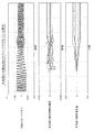
以上説明した本実施例6の空燃比検出タイミングの学習補正の一例を図23に示している。図23の例は、#1気筒の空燃比がずれている状態で気筒別空燃比制御を開始したときの制御例を示している。図23の例では、気筒別空燃比制御開始後、各タイミング(T1)〜(T6)における積算相関値は、ベースタイミング+90℃Aにおける積算相関値sumCORp90 が最大となるため、空燃比検出タイミングのずれが+30℃Aずつ小刻みに補正される。これにより、空燃比検出タイミングが最適なタイミングに精度良く補正される。 An example of the learning correction of the air-fuel ratio detection timing of the sixth embodiment described above is shown in FIG. The example of FIG. 23 shows a control example when the cylinder-by-cylinder air-fuel ratio control is started in a state where the air-fuel ratio of the # 1 cylinder is shifted. In the example of FIG. 23, the integrated correlation value at the timings (T1) to (T6) after the start of the cylinder-by-cylinder air-fuel ratio control has the maximum integrated correlation value sumCORp90 at the base timing + 90 ° C. Therefore, Deviation is corrected in small increments by + 30 ° C. Thereby, the air-fuel ratio detection timing is accurately corrected to the optimal timing.
以上説明した本実施例6では、各気筒の燃料補正係数の差分と推定空燃比の差分との積を全気筒数分積算して瞬時相関値を求める処理を、720℃A当たり複数のタイミングで実施し、各タイミング毎に瞬時相関値を所定期間積算して、複数のタイミングの積算相関値を算出した後、最も積算相関値が大きいタイミングを最もずれの少ない空燃比検出タイミングであると判断して空燃比検出タイミングのずれを学習補正するようにしたので、空燃比検出タイミングのずれを精度良く学習補正することができる。
しかも、本実施例6では、瞬時相関値を所定期間積算するようにしたので、瞬間的に発生するノイズの影響を軽減することができる利点もある。
In the sixth embodiment described above, the process of obtaining the instantaneous correlation value by integrating the product of the difference in fuel correction coefficient of each cylinder and the difference in estimated air-fuel ratio by the number of all cylinders at a plurality of timings per 720 ° C. After calculating the accumulated correlation value at a plurality of timings by integrating the instantaneous correlation value at each timing for a predetermined period, the timing with the largest accumulated correlation value is determined as the air-fuel ratio detection timing with the least deviation. Thus, the deviation in the air-fuel ratio detection timing is learned and corrected, so that the deviation in the air-fuel ratio detection timing can be learned and corrected with high accuracy.
In addition, in the sixth embodiment, since the instantaneous correlation values are integrated for a predetermined period, there is an advantage that the influence of instantaneous noise can be reduced.
尚、本実施例6では、各気筒の燃料補正係数の差分と推定空燃比の差分との積を全気筒数分積算して相関値を求めるようにしたが、特定の1つの気筒についてのみ、又は、全気筒数よりも少ない複数気筒分について相関値を求めるようにしても良い。
その他、本発明は、吸気ポート噴射エンジンに限定されず、筒内噴射エンジンにも適用して実施できる等、要旨を逸脱しない範囲で種々変更して実施できる。
In the sixth embodiment, the product of the difference between the fuel correction coefficients of each cylinder and the difference between the estimated air-fuel ratios is integrated by the number of all the cylinders to obtain the correlation value. However, only for one specific cylinder, Alternatively, correlation values may be obtained for a plurality of cylinders smaller than the total number of cylinders.
In addition, the present invention is not limited to the intake port injection engine, and can be implemented with various modifications without departing from the gist, such as being applicable to a cylinder injection engine.
11…エンジン(内燃機関)、12…吸気管、14…エアフローメータ、15…スロットルバルブ、19…吸気マニホールド、20…燃料噴射弁、22…燃料ポンプ、24…燃圧センサ、27,28…可変バルブタイミング機構、35…排気マニホールド、36…排気集合部、37…空燃比センサ、38…触媒、40…ECU(気筒別空燃比推定手段,気筒別空燃比制御手段,学習手段)
DESCRIPTION OF
Claims (4)
前記気筒別空燃比制御中に各気筒の空燃比検出タイミングを変化させて各気筒の空燃比を推定し、燃料補正前後の推定空燃比の変化量が前記燃料補正量に応じた空燃比変化量になる空燃比検出タイミングを、各気筒の空燃比を検出するのに適正な空燃比検出タイミングとして学習する学習手段を備えていることを特徴とする内燃機関の気筒別空燃比制御装置。 An air-fuel ratio sensor for detecting an air-fuel ratio of the exhaust gas is installed in an exhaust gas collecting portion where the exhaust gas of each cylinder of the internal combustion engine flows and flows, and the air-fuel ratio sensor detected at each air-fuel ratio detection timing of each cylinder A cylinder-by-cylinder air-fuel ratio estimating means for estimating the air-fuel ratio of each cylinder based on the detected value of each cylinder, and calculating a fuel correction amount for each cylinder based on the deviation between the estimated air-fuel ratio of each cylinder and the reference air-fuel ratio The cylinder-by-cylinder air-fuel ratio is provided with cylinder-by-cylinder air-fuel ratio control means for controlling the air-fuel ratio of each cylinder by correcting the fuel injection amount with the fuel correction amount (hereinafter referred to as “cylinder-by-cylinder air-fuel ratio control”). In the control device,
During said cylinder air-fuel ratio control by changing the air-fuel ratio detecting timing estimates the air-fuel ratio of each cylinder, the air-fuel ratio variation amount of change estimated air-fuel ratio before and after the fuel correction corresponding to the fuel correction amount A cylinder-by-cylinder air-fuel ratio control apparatus for an internal combustion engine, comprising: learning means for learning the air-fuel ratio detection timing to become an air-fuel ratio detection timing appropriate for detecting the air-fuel ratio of each cylinder .
Priority Applications (1)
| Application Number | Priority Date | Filing Date | Title |
|---|---|---|---|
| JP2008285056A JP4600699B2 (en) | 2003-12-04 | 2008-11-06 | Cylinder-by-cylinder air-fuel ratio control apparatus for internal combustion engine |
Applications Claiming Priority (2)
| Application Number | Priority Date | Filing Date | Title |
|---|---|---|---|
| JP2003405572 | 2003-12-04 | ||
| JP2008285056A JP4600699B2 (en) | 2003-12-04 | 2008-11-06 | Cylinder-by-cylinder air-fuel ratio control apparatus for internal combustion engine |
Related Parent Applications (1)
| Application Number | Title | Priority Date | Filing Date |
|---|---|---|---|
| JP2004251201A Division JP4321411B2 (en) | 2003-12-04 | 2004-08-31 | Cylinder-by-cylinder air-fuel ratio control apparatus for internal combustion engine |
Related Child Applications (1)
| Application Number | Title | Priority Date | Filing Date |
|---|---|---|---|
| JP2010161207A Division JP2010230016A (en) | 2003-12-04 | 2010-07-16 | Cylinder-by-cylinder air-fuel ratio controller for internal combustion engine |
Publications (2)
| Publication Number | Publication Date |
|---|---|
| JP2009052565A JP2009052565A (en) | 2009-03-12 |
| JP4600699B2 true JP4600699B2 (en) | 2010-12-15 |
Family
ID=40503821
Family Applications (2)
| Application Number | Title | Priority Date | Filing Date |
|---|---|---|---|
| JP2008285056A Active JP4600699B2 (en) | 2003-12-04 | 2008-11-06 | Cylinder-by-cylinder air-fuel ratio control apparatus for internal combustion engine |
| JP2010161207A Pending JP2010230016A (en) | 2003-12-04 | 2010-07-16 | Cylinder-by-cylinder air-fuel ratio controller for internal combustion engine |
Family Applications After (1)
| Application Number | Title | Priority Date | Filing Date |
|---|---|---|---|
| JP2010161207A Pending JP2010230016A (en) | 2003-12-04 | 2010-07-16 | Cylinder-by-cylinder air-fuel ratio controller for internal combustion engine |
Country Status (1)
| Country | Link |
|---|---|
| JP (2) | JP4600699B2 (en) |
Families Citing this family (3)
| Publication number | Priority date | Publication date | Assignee | Title |
|---|---|---|---|---|
| JP5105008B2 (en) * | 2011-03-28 | 2012-12-19 | トヨタ自動車株式会社 | Cylinder air-fuel ratio variation abnormality detecting device for multi-cylinder internal combustion engine |
| DE102013014674A1 (en) | 2013-09-04 | 2015-03-05 | Man Diesel & Turbo Se | Method for operating an internal combustion engine |
| JP6213078B2 (en) * | 2013-09-09 | 2017-10-18 | 株式会社デンソー | Cylinder-by-cylinder air-fuel ratio control apparatus for internal combustion engine |
Family Cites Families (8)
| Publication number | Priority date | Publication date | Assignee | Title |
|---|---|---|---|---|
| JP3217680B2 (en) * | 1994-12-30 | 2001-10-09 | 本田技研工業株式会社 | Fuel injection control device for internal combustion engine |
| JP3749971B2 (en) * | 1995-02-27 | 2006-03-01 | 本田技研工業株式会社 | Fuel injection control device for internal combustion engine |
| JP3822668B2 (en) * | 1995-02-25 | 2006-09-20 | 本田技研工業株式会社 | Fuel injection control device for internal combustion engine |
| JPH09189250A (en) * | 1996-01-10 | 1997-07-22 | Yamaha Motor Co Ltd | Air-fuel ratio calculating method of engine and air-fuel ratio control device |
| JPH1073049A (en) * | 1996-08-29 | 1998-03-17 | Honda Motor Co Ltd | Individual cylinder air-fuel ratio estimating device for internal combustion engine |
| JP3357572B2 (en) * | 1996-09-26 | 2002-12-16 | 本田技研工業株式会社 | Air-fuel ratio control device for internal combustion engine |
| JPH11210527A (en) * | 1998-01-21 | 1999-08-03 | Mazda Motor Corp | Air-fuel ratio controller for engine |
| JP2002030970A (en) * | 2000-07-17 | 2002-01-31 | Honda Motor Co Ltd | Combustion state control device for cylinder fuel injection type internal combustion engine |
-
2008
- 2008-11-06 JP JP2008285056A patent/JP4600699B2/en active Active
-
2010
- 2010-07-16 JP JP2010161207A patent/JP2010230016A/en active Pending
Also Published As
| Publication number | Publication date |
|---|---|
| JP2009052565A (en) | 2009-03-12 |
| JP2010230016A (en) | 2010-10-14 |
Similar Documents
| Publication | Publication Date | Title |
|---|---|---|
| JP4321411B2 (en) | Cylinder-by-cylinder air-fuel ratio control apparatus for internal combustion engine | |
| JP4420288B2 (en) | Cylinder-by-cylinder air-fuel ratio control apparatus for internal combustion engine | |
| US7487035B2 (en) | Cylinder abnormality diagnosis unit of internal combustion engine and controller of internal combustion engine | |
| US7356985B2 (en) | Air-fuel ratio controller for internal combustion engine | |
| US7707822B2 (en) | Cylinder air-fuel ratio controller for internal combustion engine | |
| US7742870B2 (en) | Air-fuel ratio control device of internal combustion engine | |
| JP2005163696A (en) | Misfire detection device of internal combustion engine | |
| US9790882B2 (en) | Individual cylinder air-fuel ratio control device of internal combustion engine | |
| US10247120B2 (en) | Cylinder-by-cylinder air-fuel ratio controller for internal combustion engine | |
| JP6213085B2 (en) | Cylinder-by-cylinder air-fuel ratio control apparatus for internal combustion engine | |
| US8645046B2 (en) | Controller for internal combustion engine | |
| JP2008128080A (en) | Control device for internal combustion engine | |
| JP6213078B2 (en) | Cylinder-by-cylinder air-fuel ratio control apparatus for internal combustion engine | |
| JP4600699B2 (en) | Cylinder-by-cylinder air-fuel ratio control apparatus for internal combustion engine | |
| JP2007211609A (en) | Device for controlling air-fuel ratio per cylinder of internal combustion engine | |
| JP4492802B2 (en) | Air-fuel ratio control device | |
| JP2008014178A (en) | Cylinder-by-cylinder air-fuel ratio control device for internal combustion engine | |
| JP2008038784A (en) | Cylinder-by-cylinder air-fuel ratio control device of internal combustion engine | |
| JP2008128161A (en) | Control device of internal combustion engine | |
| JP2016041922A (en) | Internal combustion engine cylinder-specific air-fuel ratio control unit | |
| JP7091814B2 (en) | Air-fuel ratio estimator | |
| JP2008038786A (en) | Cylinder-by-cylinder air-fuel ratio control device of internal combustion engine | |
| JP2016044575A (en) | Cylinder air-fuel ratio control device for internal combustion engine | |
| JP2007205219A (en) | Cylinder-by-cylinder air-fuel ratio control device for internal combustion engine | |
| JPH04358736A (en) | Fuel injection quantity controller |
Legal Events
| Date | Code | Title | Description |
|---|---|---|---|
| A131 | Notification of reasons for refusal |
Free format text: JAPANESE INTERMEDIATE CODE: A131 Effective date: 20100618 |
|
| A521 | Request for written amendment filed |
Free format text: JAPANESE INTERMEDIATE CODE: A523 Effective date: 20100716 |
|
| TRDD | Decision of grant or rejection written | ||
| A01 | Written decision to grant a patent or to grant a registration (utility model) |
Free format text: JAPANESE INTERMEDIATE CODE: A01 Effective date: 20100901 |
|
| A01 | Written decision to grant a patent or to grant a registration (utility model) |
Free format text: JAPANESE INTERMEDIATE CODE: A01 |
|
| A61 | First payment of annual fees (during grant procedure) |
Free format text: JAPANESE INTERMEDIATE CODE: A61 Effective date: 20100914 |
|
| FPAY | Renewal fee payment (event date is renewal date of database) |
Free format text: PAYMENT UNTIL: 20131008 Year of fee payment: 3 |
|
| R151 | Written notification of patent or utility model registration |
Ref document number: 4600699 Country of ref document: JP Free format text: JAPANESE INTERMEDIATE CODE: R151 |
|
| FPAY | Renewal fee payment (event date is renewal date of database) |
Free format text: PAYMENT UNTIL: 20131008 Year of fee payment: 3 |
|
| R250 | Receipt of annual fees |
Free format text: JAPANESE INTERMEDIATE CODE: R250 |
|
| R250 | Receipt of annual fees |
Free format text: JAPANESE INTERMEDIATE CODE: R250 |
|
| R250 | Receipt of annual fees |
Free format text: JAPANESE INTERMEDIATE CODE: R250 |
|
| R250 | Receipt of annual fees |
Free format text: JAPANESE INTERMEDIATE CODE: R250 |
|
| R250 | Receipt of annual fees |
Free format text: JAPANESE INTERMEDIATE CODE: R250 |
|
| R250 | Receipt of annual fees |
Free format text: JAPANESE INTERMEDIATE CODE: R250 |
|
| R250 | Receipt of annual fees |
Free format text: JAPANESE INTERMEDIATE CODE: R250 |
|
| R250 | Receipt of annual fees |
Free format text: JAPANESE INTERMEDIATE CODE: R250 |
|
| R250 | Receipt of annual fees |
Free format text: JAPANESE INTERMEDIATE CODE: R250 |