JP4594837B2 - Method for producing porous laminate - Google Patents
Method for producing porous laminate Download PDFInfo
- Publication number
- JP4594837B2 JP4594837B2 JP2005275134A JP2005275134A JP4594837B2 JP 4594837 B2 JP4594837 B2 JP 4594837B2 JP 2005275134 A JP2005275134 A JP 2005275134A JP 2005275134 A JP2005275134 A JP 2005275134A JP 4594837 B2 JP4594837 B2 JP 4594837B2
- Authority
- JP
- Japan
- Prior art keywords
- porous
- laminate
- intermediate layer
- resin
- filler
- Prior art date
- Legal status (The legal status is an assumption and is not a legal conclusion. Google has not performed a legal analysis and makes no representation as to the accuracy of the status listed.)
- Active
Links
- 238000004519 manufacturing process Methods 0.000 title claims description 31
- 238000000034 method Methods 0.000 claims description 94
- -1 polypropylene Polymers 0.000 claims description 91
- 229920005992 thermoplastic resin Polymers 0.000 claims description 68
- 239000000945 filler Substances 0.000 claims description 53
- 239000012530 fluid Substances 0.000 claims description 43
- 229920005989 resin Polymers 0.000 claims description 43
- 239000011347 resin Substances 0.000 claims description 43
- CURLTUGMZLYLDI-UHFFFAOYSA-N Carbon dioxide Chemical group O=C=O CURLTUGMZLYLDI-UHFFFAOYSA-N 0.000 claims description 32
- 239000011342 resin composition Substances 0.000 claims description 30
- 239000004743 Polypropylene Substances 0.000 claims description 27
- 239000000203 mixture Substances 0.000 claims description 27
- 230000035699 permeability Effects 0.000 claims description 27
- 229920001155 polypropylene Polymers 0.000 claims description 27
- IJGRMHOSHXDMSA-UHFFFAOYSA-N Atomic nitrogen Chemical compound N#N IJGRMHOSHXDMSA-UHFFFAOYSA-N 0.000 claims description 21
- 239000001569 carbon dioxide Substances 0.000 claims description 16
- 229910002092 carbon dioxide Inorganic materials 0.000 claims description 16
- 238000004891 communication Methods 0.000 claims description 11
- 229910052757 nitrogen Inorganic materials 0.000 claims description 8
- 230000008016 vaporization Effects 0.000 claims description 5
- 229920000573 polyethylene Polymers 0.000 description 29
- 239000004698 Polyethylene Substances 0.000 description 28
- 229920000642 polymer Polymers 0.000 description 27
- 229920000181 Ethylene propylene rubber Polymers 0.000 description 20
- TZCXTZWJZNENPQ-UHFFFAOYSA-L barium sulfate Chemical compound [Ba+2].[O-]S([O-])(=O)=O TZCXTZWJZNENPQ-UHFFFAOYSA-L 0.000 description 20
- VGGSQFUCUMXWEO-UHFFFAOYSA-N Ethene Chemical compound C=C VGGSQFUCUMXWEO-UHFFFAOYSA-N 0.000 description 19
- 239000005977 Ethylene Substances 0.000 description 19
- 239000007789 gas Substances 0.000 description 16
- 230000008018 melting Effects 0.000 description 15
- 238000002844 melting Methods 0.000 description 15
- 239000004014 plasticizer Substances 0.000 description 15
- 229920001577 copolymer Polymers 0.000 description 14
- 239000003960 organic solvent Substances 0.000 description 14
- 239000002245 particle Substances 0.000 description 14
- 239000000126 substance Substances 0.000 description 14
- 230000000052 comparative effect Effects 0.000 description 13
- 239000011148 porous material Substances 0.000 description 13
- 239000000654 additive Substances 0.000 description 12
- 150000001336 alkenes Chemical class 0.000 description 12
- 150000001875 compounds Chemical class 0.000 description 12
- 238000010438 heat treatment Methods 0.000 description 12
- QQONPFPTGQHPMA-UHFFFAOYSA-N propylene Natural products CC=C QQONPFPTGQHPMA-UHFFFAOYSA-N 0.000 description 12
- 230000001965 increasing effect Effects 0.000 description 11
- 125000004805 propylene group Chemical group [H]C([H])([H])C([H])([*:1])C([H])([H])[*:2] 0.000 description 11
- 229920001971 elastomer Polymers 0.000 description 10
- 239000007788 liquid Substances 0.000 description 10
- 238000005259 measurement Methods 0.000 description 10
- 238000002156 mixing Methods 0.000 description 10
- JRZJOMJEPLMPRA-UHFFFAOYSA-N olefin Natural products CCCCCCCC=C JRZJOMJEPLMPRA-UHFFFAOYSA-N 0.000 description 10
- 230000000996 additive effect Effects 0.000 description 9
- 239000004359 castor oil Substances 0.000 description 9
- 229920001903 high density polyethylene Polymers 0.000 description 9
- 239000004700 high-density polyethylene Substances 0.000 description 9
- 239000000463 material Substances 0.000 description 9
- 230000008569 process Effects 0.000 description 9
- WSSSPWUEQFSQQG-UHFFFAOYSA-N 4-methyl-1-pentene Chemical compound CC(C)CC=C WSSSPWUEQFSQQG-UHFFFAOYSA-N 0.000 description 8
- VTYYLEPIZMXCLO-UHFFFAOYSA-L Calcium carbonate Chemical compound [Ca+2].[O-]C([O-])=O VTYYLEPIZMXCLO-UHFFFAOYSA-L 0.000 description 8
- GQPLMRYTRLFLPF-UHFFFAOYSA-N Nitrous Oxide Chemical compound [O-][N+]#N GQPLMRYTRLFLPF-UHFFFAOYSA-N 0.000 description 8
- 239000004793 Polystyrene Substances 0.000 description 8
- PPBRXRYQALVLMV-UHFFFAOYSA-N Styrene Chemical compound C=CC1=CC=CC=C1 PPBRXRYQALVLMV-UHFFFAOYSA-N 0.000 description 8
- 235000019438 castor oil Nutrition 0.000 description 8
- 238000005187 foaming Methods 0.000 description 8
- ZEMPKEQAKRGZGQ-XOQCFJPHSA-N glycerol triricinoleate Natural products CCCCCC[C@@H](O)CC=CCCCCCCCC(=O)OC[C@@H](COC(=O)CCCCCCCC=CC[C@@H](O)CCCCCC)OC(=O)CCCCCCCC=CC[C@H](O)CCCCCC ZEMPKEQAKRGZGQ-XOQCFJPHSA-N 0.000 description 8
- 238000000465 moulding Methods 0.000 description 8
- 239000002904 solvent Substances 0.000 description 8
- 229910052783 alkali metal Inorganic materials 0.000 description 7
- 150000001340 alkali metals Chemical class 0.000 description 7
- 239000011255 nonaqueous electrolyte Substances 0.000 description 7
- 229920002857 polybutadiene Polymers 0.000 description 7
- 229920000728 polyester Polymers 0.000 description 7
- 229920013716 polyethylene resin Polymers 0.000 description 7
- 229920002223 polystyrene Polymers 0.000 description 7
- 239000000243 solution Substances 0.000 description 7
- XLYOFNOQVPJJNP-UHFFFAOYSA-N water Substances O XLYOFNOQVPJJNP-UHFFFAOYSA-N 0.000 description 7
- 239000004711 α-olefin Substances 0.000 description 7
- VXNZUUAINFGPBY-UHFFFAOYSA-N 1-Butene Chemical compound CCC=C VXNZUUAINFGPBY-UHFFFAOYSA-N 0.000 description 6
- AFFLGGQVNFXPEV-UHFFFAOYSA-N 1-decene Chemical compound CCCCCCCCC=C AFFLGGQVNFXPEV-UHFFFAOYSA-N 0.000 description 6
- LIKMAJRDDDTEIG-UHFFFAOYSA-N 1-hexene Chemical compound CCCCC=C LIKMAJRDDDTEIG-UHFFFAOYSA-N 0.000 description 6
- KWKAKUADMBZCLK-UHFFFAOYSA-N 1-octene Chemical compound CCCCCCC=C KWKAKUADMBZCLK-UHFFFAOYSA-N 0.000 description 6
- XPDWGBQVDMORPB-UHFFFAOYSA-N Fluoroform Chemical compound FC(F)F XPDWGBQVDMORPB-UHFFFAOYSA-N 0.000 description 6
- 239000005062 Polybutadiene Substances 0.000 description 6
- HQQADJVZYDDRJT-UHFFFAOYSA-N ethene;prop-1-ene Chemical group C=C.CC=C HQQADJVZYDDRJT-UHFFFAOYSA-N 0.000 description 6
- 229920001519 homopolymer Polymers 0.000 description 6
- 239000011256 inorganic filler Substances 0.000 description 6
- 229910003475 inorganic filler Inorganic materials 0.000 description 6
- 238000006116 polymerization reaction Methods 0.000 description 6
- 229920005672 polyolefin resin Polymers 0.000 description 6
- 239000005060 rubber Substances 0.000 description 6
- OKTJSMMVPCPJKN-UHFFFAOYSA-N Carbon Chemical compound [C] OKTJSMMVPCPJKN-UHFFFAOYSA-N 0.000 description 5
- 229920001400 block copolymer Polymers 0.000 description 5
- 125000004432 carbon atom Chemical group C* 0.000 description 5
- 239000003795 chemical substances by application Substances 0.000 description 5
- 238000013329 compounding Methods 0.000 description 5
- 229920003244 diene elastomer Polymers 0.000 description 5
- 235000014113 dietary fatty acids Nutrition 0.000 description 5
- 229910001873 dinitrogen Inorganic materials 0.000 description 5
- 239000008151 electrolyte solution Substances 0.000 description 5
- 239000000194 fatty acid Substances 0.000 description 5
- 229930195729 fatty acid Natural products 0.000 description 5
- 150000004665 fatty acids Chemical class 0.000 description 5
- VLKZOEOYAKHREP-UHFFFAOYSA-N n-Hexane Chemical compound CCCCCC VLKZOEOYAKHREP-UHFFFAOYSA-N 0.000 description 5
- 239000003921 oil Substances 0.000 description 5
- 235000019198 oils Nutrition 0.000 description 5
- 238000005191 phase separation Methods 0.000 description 5
- 229920002647 polyamide Polymers 0.000 description 5
- BQCIDUSAKPWEOX-UHFFFAOYSA-N 1,1-Difluoroethene Chemical group FC(F)=C BQCIDUSAKPWEOX-UHFFFAOYSA-N 0.000 description 4
- ULQISTXYYBZJSJ-UHFFFAOYSA-N 12-hydroxyoctadecanoic acid Chemical compound CCCCCCC(O)CCCCCCCCCCC(O)=O ULQISTXYYBZJSJ-UHFFFAOYSA-N 0.000 description 4
- OTMSDBZUPAUEDD-UHFFFAOYSA-N Ethane Chemical compound CC OTMSDBZUPAUEDD-UHFFFAOYSA-N 0.000 description 4
- LYCAIKOWRPUZTN-UHFFFAOYSA-N Ethylene glycol Chemical compound OCCO LYCAIKOWRPUZTN-UHFFFAOYSA-N 0.000 description 4
- YCKRFDGAMUMZLT-UHFFFAOYSA-N Fluorine atom Chemical compound [F] YCKRFDGAMUMZLT-UHFFFAOYSA-N 0.000 description 4
- KFZMGEQAYNKOFK-UHFFFAOYSA-N Isopropanol Chemical compound CC(C)O KFZMGEQAYNKOFK-UHFFFAOYSA-N 0.000 description 4
- 235000021355 Stearic acid Nutrition 0.000 description 4
- 229910000019 calcium carbonate Inorganic materials 0.000 description 4
- 239000003575 carbonaceous material Substances 0.000 description 4
- 229920006026 co-polymeric resin Polymers 0.000 description 4
- 239000000806 elastomer Substances 0.000 description 4
- 239000003792 electrolyte Substances 0.000 description 4
- 238000001125 extrusion Methods 0.000 description 4
- 239000011737 fluorine Substances 0.000 description 4
- 229910052731 fluorine Inorganic materials 0.000 description 4
- 239000011261 inert gas Substances 0.000 description 4
- 229920001684 low density polyethylene Polymers 0.000 description 4
- 239000004702 low-density polyethylene Substances 0.000 description 4
- 239000000178 monomer Substances 0.000 description 4
- 239000001272 nitrous oxide Substances 0.000 description 4
- GLDOVTGHNKAZLK-UHFFFAOYSA-N octadecan-1-ol Chemical compound CCCCCCCCCCCCCCCCCCO GLDOVTGHNKAZLK-UHFFFAOYSA-N 0.000 description 4
- QIQXTHQIDYTFRH-UHFFFAOYSA-N octadecanoic acid Chemical compound CCCCCCCCCCCCCCCCCC(O)=O QIQXTHQIDYTFRH-UHFFFAOYSA-N 0.000 description 4
- OQCDKBAXFALNLD-UHFFFAOYSA-N octadecanoic acid Natural products CCCCCCCC(C)CCCCCCCCC(O)=O OQCDKBAXFALNLD-UHFFFAOYSA-N 0.000 description 4
- 239000012188 paraffin wax Substances 0.000 description 4
- 239000008188 pellet Substances 0.000 description 4
- 239000004417 polycarbonate Substances 0.000 description 4
- 229920000515 polycarbonate Polymers 0.000 description 4
- 229920001195 polyisoprene Polymers 0.000 description 4
- 229920001343 polytetrafluoroethylene Polymers 0.000 description 4
- 239000004810 polytetrafluoroethylene Substances 0.000 description 4
- 239000000843 powder Substances 0.000 description 4
- 229920005604 random copolymer Polymers 0.000 description 4
- 238000000926 separation method Methods 0.000 description 4
- 239000002002 slurry Substances 0.000 description 4
- CSCPPACGZOOCGX-UHFFFAOYSA-N Acetone Chemical compound CC(C)=O CSCPPACGZOOCGX-UHFFFAOYSA-N 0.000 description 3
- WEVYAHXRMPXWCK-UHFFFAOYSA-N Acetonitrile Chemical compound CC#N WEVYAHXRMPXWCK-UHFFFAOYSA-N 0.000 description 3
- YMWUJEATGCHHMB-UHFFFAOYSA-N Dichloromethane Chemical compound ClCCl YMWUJEATGCHHMB-UHFFFAOYSA-N 0.000 description 3
- 239000004593 Epoxy Substances 0.000 description 3
- LFQSCWFLJHTTHZ-UHFFFAOYSA-N Ethanol Chemical compound CCO LFQSCWFLJHTTHZ-UHFFFAOYSA-N 0.000 description 3
- KMTRUDSVKNLOMY-UHFFFAOYSA-N Ethylene carbonate Chemical compound O=C1OCCO1 KMTRUDSVKNLOMY-UHFFFAOYSA-N 0.000 description 3
- WHXSMMKQMYFTQS-UHFFFAOYSA-N Lithium Chemical compound [Li] WHXSMMKQMYFTQS-UHFFFAOYSA-N 0.000 description 3
- HBBGRARXTFLTSG-UHFFFAOYSA-N Lithium ion Chemical compound [Li+] HBBGRARXTFLTSG-UHFFFAOYSA-N 0.000 description 3
- XTXRWKRVRITETP-UHFFFAOYSA-N Vinyl acetate Chemical compound CC(=O)OC=C XTXRWKRVRITETP-UHFFFAOYSA-N 0.000 description 3
- 230000008901 benefit Effects 0.000 description 3
- 150000007942 carboxylates Chemical class 0.000 description 3
- 239000003054 catalyst Substances 0.000 description 3
- 150000001993 dienes Chemical class 0.000 description 3
- 238000009792 diffusion process Methods 0.000 description 3
- 150000002148 esters Chemical class 0.000 description 3
- 238000001704 evaporation Methods 0.000 description 3
- 230000008020 evaporation Effects 0.000 description 3
- 239000010439 graphite Substances 0.000 description 3
- 229910002804 graphite Inorganic materials 0.000 description 3
- WMIYKQLTONQJES-UHFFFAOYSA-N hexafluoroethane Chemical compound FC(F)(F)C(F)(F)F WMIYKQLTONQJES-UHFFFAOYSA-N 0.000 description 3
- FUZZWVXGSFPDMH-UHFFFAOYSA-N hexanoic acid Chemical compound CCCCCC(O)=O FUZZWVXGSFPDMH-UHFFFAOYSA-N 0.000 description 3
- 238000005470 impregnation Methods 0.000 description 3
- 229920003049 isoprene rubber Polymers 0.000 description 3
- 229940057995 liquid paraffin Drugs 0.000 description 3
- 229910052744 lithium Inorganic materials 0.000 description 3
- 229910001416 lithium ion Inorganic materials 0.000 description 3
- 239000000155 melt Substances 0.000 description 3
- 239000012528 membrane Substances 0.000 description 3
- TVMXDCGIABBOFY-UHFFFAOYSA-N n-Octanol Natural products CCCCCCCC TVMXDCGIABBOFY-UHFFFAOYSA-N 0.000 description 3
- 239000012766 organic filler Substances 0.000 description 3
- 238000004806 packaging method and process Methods 0.000 description 3
- 229920001083 polybutene Polymers 0.000 description 3
- 229920000098 polyolefin Polymers 0.000 description 3
- 238000002360 preparation method Methods 0.000 description 3
- 229920001384 propylene homopolymer Polymers 0.000 description 3
- 150000003839 salts Chemical class 0.000 description 3
- 239000008117 stearic acid Substances 0.000 description 3
- TXEYQDLBPFQVAA-UHFFFAOYSA-N tetrafluoromethane Chemical compound FC(F)(F)F TXEYQDLBPFQVAA-UHFFFAOYSA-N 0.000 description 3
- ZGEGCLOFRBLKSE-UHFFFAOYSA-N 1-Heptene Chemical compound CCCCCC=C ZGEGCLOFRBLKSE-UHFFFAOYSA-N 0.000 description 2
- YBYIRNPNPLQARY-UHFFFAOYSA-N 1H-indene Chemical compound C1=CC=C2CC=CC2=C1 YBYIRNPNPLQARY-UHFFFAOYSA-N 0.000 description 2
- YEJRWHAVMIAJKC-UHFFFAOYSA-N 4-Butyrolactone Chemical compound O=C1CCCO1 YEJRWHAVMIAJKC-UHFFFAOYSA-N 0.000 description 2
- 229920000178 Acrylic resin Polymers 0.000 description 2
- 239000004925 Acrylic resin Substances 0.000 description 2
- XTHFKEDIFFGKHM-UHFFFAOYSA-N Dimethoxyethane Chemical compound COCCOC XTHFKEDIFFGKHM-UHFFFAOYSA-N 0.000 description 2
- 229920002943 EPDM rubber Polymers 0.000 description 2
- OAKJQQAXSVQMHS-UHFFFAOYSA-N Hydrazine Chemical compound NN OAKJQQAXSVQMHS-UHFFFAOYSA-N 0.000 description 2
- TWRXJAOTZQYOKJ-UHFFFAOYSA-L Magnesium chloride Chemical compound [Mg+2].[Cl-].[Cl-] TWRXJAOTZQYOKJ-UHFFFAOYSA-L 0.000 description 2
- CSNNHWWHGAXBCP-UHFFFAOYSA-L Magnesium sulfate Chemical compound [Mg+2].[O-][S+2]([O-])([O-])[O-] CSNNHWWHGAXBCP-UHFFFAOYSA-L 0.000 description 2
- SECXISVLQFMRJM-UHFFFAOYSA-N N-Methylpyrrolidone Chemical compound CN1CCCC1=O SECXISVLQFMRJM-UHFFFAOYSA-N 0.000 description 2
- XYFCBTPGUUZFHI-UHFFFAOYSA-N Phosphine Chemical compound P XYFCBTPGUUZFHI-UHFFFAOYSA-N 0.000 description 2
- 239000004952 Polyamide Substances 0.000 description 2
- 239000004721 Polyphenylene oxide Substances 0.000 description 2
- ZLMJMSJWJFRBEC-UHFFFAOYSA-N Potassium Chemical compound [K] ZLMJMSJWJFRBEC-UHFFFAOYSA-N 0.000 description 2
- VYPSYNLAJGMNEJ-UHFFFAOYSA-N Silicium dioxide Chemical compound O=[Si]=O VYPSYNLAJGMNEJ-UHFFFAOYSA-N 0.000 description 2
- FAPWRFPIFSIZLT-UHFFFAOYSA-M Sodium chloride Chemical compound [Na+].[Cl-] FAPWRFPIFSIZLT-UHFFFAOYSA-M 0.000 description 2
- WYURNTSHIVDZCO-UHFFFAOYSA-N Tetrahydrofuran Chemical compound C1CCOC1 WYURNTSHIVDZCO-UHFFFAOYSA-N 0.000 description 2
- GWEVSGVZZGPLCZ-UHFFFAOYSA-N Titan oxide Chemical compound O=[Ti]=O GWEVSGVZZGPLCZ-UHFFFAOYSA-N 0.000 description 2
- 239000004699 Ultra-high molecular weight polyethylene Substances 0.000 description 2
- 241000405115 Zela Species 0.000 description 2
- XLOMVQKBTHCTTD-UHFFFAOYSA-N Zinc monoxide Chemical compound [Zn]=O XLOMVQKBTHCTTD-UHFFFAOYSA-N 0.000 description 2
- 239000011354 acetal resin Substances 0.000 description 2
- 230000002378 acidificating effect Effects 0.000 description 2
- 229910052782 aluminium Inorganic materials 0.000 description 2
- XAGFODPZIPBFFR-UHFFFAOYSA-N aluminium Chemical compound [Al] XAGFODPZIPBFFR-UHFFFAOYSA-N 0.000 description 2
- 239000003963 antioxidant agent Substances 0.000 description 2
- AYJRCSIUFZENHW-UHFFFAOYSA-L barium carbonate Chemical compound [Ba+2].[O-]C([O-])=O AYJRCSIUFZENHW-UHFFFAOYSA-L 0.000 description 2
- WTEOIRVLGSZEPR-UHFFFAOYSA-N boron trifluoride Chemical compound FB(F)F WTEOIRVLGSZEPR-UHFFFAOYSA-N 0.000 description 2
- OSGAYBCDTDRGGQ-UHFFFAOYSA-L calcium sulfate Chemical compound [Ca+2].[O-]S([O-])(=O)=O OSGAYBCDTDRGGQ-UHFFFAOYSA-L 0.000 description 2
- 239000002482 conductive additive Substances 0.000 description 2
- DIOQZVSQGTUSAI-UHFFFAOYSA-N decane Chemical compound CCCCCCCCCC DIOQZVSQGTUSAI-UHFFFAOYSA-N 0.000 description 2
- 230000003247 decreasing effect Effects 0.000 description 2
- GNTDGMZSJNCJKK-UHFFFAOYSA-N divanadium pentaoxide Chemical compound O=[V](=O)O[V](=O)=O GNTDGMZSJNCJKK-UHFFFAOYSA-N 0.000 description 2
- POULHZVOKOAJMA-UHFFFAOYSA-N dodecanoic acid Chemical compound CCCCCCCCCCCC(O)=O POULHZVOKOAJMA-UHFFFAOYSA-N 0.000 description 2
- 238000005530 etching Methods 0.000 description 2
- 150000002170 ethers Chemical class 0.000 description 2
- 238000002474 experimental method Methods 0.000 description 2
- 238000000605 extraction Methods 0.000 description 2
- NBVXSUQYWXRMNV-UHFFFAOYSA-N fluoromethane Chemical compound FC NBVXSUQYWXRMNV-UHFFFAOYSA-N 0.000 description 2
- GAEKPEKOJKCEMS-UHFFFAOYSA-N gamma-valerolactone Chemical compound CC1CCC(=O)O1 GAEKPEKOJKCEMS-UHFFFAOYSA-N 0.000 description 2
- 239000011521 glass Substances 0.000 description 2
- 239000008187 granular material Substances 0.000 description 2
- 238000009998 heat setting Methods 0.000 description 2
- IPCSVZSSVZVIGE-UHFFFAOYSA-N hexadecanoic acid Chemical compound CCCCCCCCCCCCCCCC(O)=O IPCSVZSSVZVIGE-UHFFFAOYSA-N 0.000 description 2
- 229920001477 hydrophilic polymer Polymers 0.000 description 2
- WGCNASOHLSPBMP-UHFFFAOYSA-N hydroxyacetaldehyde Natural products OCC=O WGCNASOHLSPBMP-UHFFFAOYSA-N 0.000 description 2
- 230000006872 improvement Effects 0.000 description 2
- 230000010220 ion permeability Effects 0.000 description 2
- 150000002500 ions Chemical class 0.000 description 2
- 239000003350 kerosene Substances 0.000 description 2
- 238000003475 lamination Methods 0.000 description 2
- 244000144972 livestock Species 0.000 description 2
- 230000007257 malfunction Effects 0.000 description 2
- NUJOXMJBOLGQSY-UHFFFAOYSA-N manganese dioxide Chemical compound O=[Mn]=O NUJOXMJBOLGQSY-UHFFFAOYSA-N 0.000 description 2
- 229910044991 metal oxide Inorganic materials 0.000 description 2
- 150000004706 metal oxides Chemical class 0.000 description 2
- 239000002480 mineral oil Substances 0.000 description 2
- 235000010446 mineral oil Nutrition 0.000 description 2
- GOQYKNQRPGWPLP-UHFFFAOYSA-N n-heptadecyl alcohol Natural products CCCCCCCCCCCCCCCCCO GOQYKNQRPGWPLP-UHFFFAOYSA-N 0.000 description 2
- 230000007935 neutral effect Effects 0.000 description 2
- 231100000252 nontoxic Toxicity 0.000 description 2
- 230000003000 nontoxic effect Effects 0.000 description 2
- 239000006259 organic additive Substances 0.000 description 2
- 239000005022 packaging material Substances 0.000 description 2
- YWAKXRMUMFPDSH-UHFFFAOYSA-N pentene Chemical compound CCCC=C YWAKXRMUMFPDSH-UHFFFAOYSA-N 0.000 description 2
- 229920001515 polyalkylene glycol Polymers 0.000 description 2
- 229920006122 polyamide resin Polymers 0.000 description 2
- 229920001707 polybutylene terephthalate Polymers 0.000 description 2
- 229920000570 polyether Polymers 0.000 description 2
- 229920005638 polyethylene monopolymer Polymers 0.000 description 2
- 229920006324 polyoxymethylene Polymers 0.000 description 2
- 239000011118 polyvinyl acetate Substances 0.000 description 2
- 229920002689 polyvinyl acetate Polymers 0.000 description 2
- 239000011591 potassium Substances 0.000 description 2
- 229910052700 potassium Inorganic materials 0.000 description 2
- 238000004886 process control Methods 0.000 description 2
- 239000010935 stainless steel Substances 0.000 description 2
- 229910001220 stainless steel Inorganic materials 0.000 description 2
- HXJUTPCZVOIRIF-UHFFFAOYSA-N sulfolane Chemical compound O=S1(=O)CCCC1 HXJUTPCZVOIRIF-UHFFFAOYSA-N 0.000 description 2
- 150000003871 sulfonates Chemical class 0.000 description 2
- 239000012756 surface treatment agent Substances 0.000 description 2
- 239000004094 surface-active agent Substances 0.000 description 2
- BFKJFAAPBSQJPD-UHFFFAOYSA-N tetrafluoroethene Chemical group FC(F)=C(F)F BFKJFAAPBSQJPD-UHFFFAOYSA-N 0.000 description 2
- OGIDPMRJRNCKJF-UHFFFAOYSA-N titanium oxide Inorganic materials [Ti]=O OGIDPMRJRNCKJF-UHFFFAOYSA-N 0.000 description 2
- 150000005691 triesters Chemical class 0.000 description 2
- 229920000785 ultra high molecular weight polyethylene Polymers 0.000 description 2
- 238000005406 washing Methods 0.000 description 2
- 238000004804 winding Methods 0.000 description 2
- PRBHEGAFLDMLAL-GQCTYLIASA-N (4e)-hexa-1,4-diene Chemical compound C\C=C\CC=C PRBHEGAFLDMLAL-GQCTYLIASA-N 0.000 description 1
- OJOWICOBYCXEKR-KRXBUXKQSA-N (5e)-5-ethylidenebicyclo[2.2.1]hept-2-ene Chemical compound C1C2C(=C/C)/CC1C=C2 OJOWICOBYCXEKR-KRXBUXKQSA-N 0.000 description 1
- ALSTYHKOOCGGFT-KTKRTIGZSA-N (9Z)-octadecen-1-ol Chemical compound CCCCCCCC\C=C/CCCCCCCCO ALSTYHKOOCGGFT-KTKRTIGZSA-N 0.000 description 1
- WRIDQFICGBMAFQ-UHFFFAOYSA-N (E)-8-Octadecenoic acid Natural products CCCCCCCCCC=CCCCCCCC(O)=O WRIDQFICGBMAFQ-UHFFFAOYSA-N 0.000 description 1
- LVGUZGTVOIAKKC-UHFFFAOYSA-N 1,1,1,2-tetrafluoroethane Chemical compound FCC(F)(F)F LVGUZGTVOIAKKC-UHFFFAOYSA-N 0.000 description 1
- DHKHKXVYLBGOIT-UHFFFAOYSA-N 1,1-Diethoxyethane Chemical compound CCOC(C)OCC DHKHKXVYLBGOIT-UHFFFAOYSA-N 0.000 description 1
- ZZXUZKXVROWEIF-UHFFFAOYSA-N 1,2-butylene carbonate Chemical compound CCC1COC(=O)O1 ZZXUZKXVROWEIF-UHFFFAOYSA-N 0.000 description 1
- WNXJIVFYUVYPPR-UHFFFAOYSA-N 1,3-dioxolane Chemical compound C1COCO1 WNXJIVFYUVYPPR-UHFFFAOYSA-N 0.000 description 1
- VBICKXHEKHSIBG-UHFFFAOYSA-N 1-monostearoylglycerol Chemical compound CCCCCCCCCCCCCCCCCC(=O)OCC(O)CO VBICKXHEKHSIBG-UHFFFAOYSA-N 0.000 description 1
- IGGDKDTUCAWDAN-UHFFFAOYSA-N 1-vinylnaphthalene Chemical compound C1=CC=C2C(C=C)=CC=CC2=C1 IGGDKDTUCAWDAN-UHFFFAOYSA-N 0.000 description 1
- HECLRDQVFMWTQS-RGOKHQFPSA-N 1755-01-7 Chemical compound C1[C@H]2[C@@H]3CC=C[C@@H]3[C@@H]1C=C2 HECLRDQVFMWTQS-RGOKHQFPSA-N 0.000 description 1
- HEWZVZIVELJPQZ-UHFFFAOYSA-N 2,2-dimethoxypropane Chemical compound COC(C)(C)OC HEWZVZIVELJPQZ-UHFFFAOYSA-N 0.000 description 1
- JJGBFZZXKPWGCW-UHFFFAOYSA-N 2,3-bis[8-[3-[(3-pentyloxiran-2-yl)methyl]oxiran-2-yl]octanoyloxy]propyl 8-[3-[(3-pentyloxiran-2-yl)methyl]oxiran-2-yl]octanoate Chemical compound CCCCCC1OC1CC1C(CCCCCCCC(=O)OCC(COC(=O)CCCCCCCC2C(O2)CC2C(O2)CCCCC)OC(=O)CCCCCCCC2C(O2)CC2C(O2)CCCCC)O1 JJGBFZZXKPWGCW-UHFFFAOYSA-N 0.000 description 1
- AFTBJQDQENGCPC-UHFFFAOYSA-N 2,5-ditert-butyl-4-methylphenol Chemical compound CC1=CC(C(C)(C)C)=C(O)C=C1C(C)(C)C AFTBJQDQENGCPC-UHFFFAOYSA-N 0.000 description 1
- SYNPRNNJJLRHTI-UHFFFAOYSA-N 2-(hydroxymethyl)butane-1,4-diol Chemical compound OCCC(CO)CO SYNPRNNJJLRHTI-UHFFFAOYSA-N 0.000 description 1
- ROHFBIREHKPELA-UHFFFAOYSA-N 2-[(3,5-ditert-butyl-4-hydroxyphenyl)methyl]prop-2-enoic acid;methane Chemical compound C.CC(C)(C)C1=CC(CC(=C)C(O)=O)=CC(C(C)(C)C)=C1O.CC(C)(C)C1=CC(CC(=C)C(O)=O)=CC(C(C)(C)C)=C1O.CC(C)(C)C1=CC(CC(=C)C(O)=O)=CC(C(C)(C)C)=C1O.CC(C)(C)C1=CC(CC(=C)C(O)=O)=CC(C(C)(C)C)=C1O ROHFBIREHKPELA-UHFFFAOYSA-N 0.000 description 1
- HVYJSOSGTDINLW-UHFFFAOYSA-N 2-[dimethyl(octadecyl)azaniumyl]acetate Chemical compound CCCCCCCCCCCCCCCCCC[N+](C)(C)CC([O-])=O HVYJSOSGTDINLW-UHFFFAOYSA-N 0.000 description 1
- CYEJMVLDXAUOPN-UHFFFAOYSA-N 2-dodecylphenol Chemical compound CCCCCCCCCCCCC1=CC=CC=C1O CYEJMVLDXAUOPN-UHFFFAOYSA-N 0.000 description 1
- CFEMBVVZPUEPPP-UHFFFAOYSA-N 2-methylbuta-1,3-diene;prop-2-enenitrile Chemical compound C=CC#N.CC(=C)C=C CFEMBVVZPUEPPP-UHFFFAOYSA-N 0.000 description 1
- JWUJQDFVADABEY-UHFFFAOYSA-N 2-methyltetrahydrofuran Chemical compound CC1CCCO1 JWUJQDFVADABEY-UHFFFAOYSA-N 0.000 description 1
- LQJBNNIYVWPHFW-UHFFFAOYSA-N 20:1omega9c fatty acid Natural products CCCCCCCCCCC=CCCCCCCCC(O)=O LQJBNNIYVWPHFW-UHFFFAOYSA-N 0.000 description 1
- JLBJTVDPSNHSKJ-UHFFFAOYSA-N 4-Methylstyrene Chemical compound CC1=CC=C(C=C)C=C1 JLBJTVDPSNHSKJ-UHFFFAOYSA-N 0.000 description 1
- SBUOHGKIOVRDKY-UHFFFAOYSA-N 4-methyl-1,3-dioxolane Chemical compound CC1COCO1 SBUOHGKIOVRDKY-UHFFFAOYSA-N 0.000 description 1
- GZVHEAJQGPRDLQ-UHFFFAOYSA-N 6-phenyl-1,3,5-triazine-2,4-diamine Chemical compound NC1=NC(N)=NC(C=2C=CC=CC=2)=N1 GZVHEAJQGPRDLQ-UHFFFAOYSA-N 0.000 description 1
- QSBYPNXLFMSGKH-UHFFFAOYSA-N 9-Heptadecensaeure Natural products CCCCCCCC=CCCCCCCCC(O)=O QSBYPNXLFMSGKH-UHFFFAOYSA-N 0.000 description 1
- HSFWRNGVRCDJHI-UHFFFAOYSA-N Acetylene Chemical compound C#C HSFWRNGVRCDJHI-UHFFFAOYSA-N 0.000 description 1
- 229910015900 BF3 Inorganic materials 0.000 description 1
- DKPFZGUDAPQIHT-UHFFFAOYSA-N Butyl acetate Natural products CCCCOC(C)=O DKPFZGUDAPQIHT-UHFFFAOYSA-N 0.000 description 1
- UXVMQQNJUSDDNG-UHFFFAOYSA-L Calcium chloride Chemical compound [Cl-].[Cl-].[Ca+2] UXVMQQNJUSDDNG-UHFFFAOYSA-L 0.000 description 1
- 229920000049 Carbon (fiber) Polymers 0.000 description 1
- RYGMFSIKBFXOCR-UHFFFAOYSA-N Copper Chemical compound [Cu] RYGMFSIKBFXOCR-UHFFFAOYSA-N 0.000 description 1
- VEXZGXHMUGYJMC-DYCDLGHISA-N Deuterium chloride Chemical compound [2H]Cl VEXZGXHMUGYJMC-DYCDLGHISA-N 0.000 description 1
- VEXZGXHMUGYJMC-UHFFFAOYSA-N Hydrochloric acid Chemical compound Cl VEXZGXHMUGYJMC-UHFFFAOYSA-N 0.000 description 1
- DGAQECJNVWCQMB-PUAWFVPOSA-M Ilexoside XXIX Chemical compound C[C@@H]1CC[C@@]2(CC[C@@]3(C(=CC[C@H]4[C@]3(CC[C@@H]5[C@@]4(CC[C@@H](C5(C)C)OS(=O)(=O)[O-])C)C)[C@@H]2[C@]1(C)O)C)C(=O)O[C@H]6[C@@H]([C@H]([C@@H]([C@H](O6)CO)O)O)O.[Na+] DGAQECJNVWCQMB-PUAWFVPOSA-M 0.000 description 1
- OWYWGLHRNBIFJP-UHFFFAOYSA-N Ipazine Chemical compound CCN(CC)C1=NC(Cl)=NC(NC(C)C)=N1 OWYWGLHRNBIFJP-UHFFFAOYSA-N 0.000 description 1
- VHOQXEIFYTTXJU-UHFFFAOYSA-N Isobutylene-isoprene copolymer Chemical compound CC(C)=C.CC(=C)C=C VHOQXEIFYTTXJU-UHFFFAOYSA-N 0.000 description 1
- 239000005639 Lauric acid Substances 0.000 description 1
- 229910012851 LiCoO 2 Inorganic materials 0.000 description 1
- 229910013870 LiPF 6 Inorganic materials 0.000 description 1
- FYYHWMGAXLPEAU-UHFFFAOYSA-N Magnesium Chemical compound [Mg] FYYHWMGAXLPEAU-UHFFFAOYSA-N 0.000 description 1
- 229920000877 Melamine resin Polymers 0.000 description 1
- RJUFJBKOKNCXHH-UHFFFAOYSA-N Methyl propionate Chemical compound CCC(=O)OC RJUFJBKOKNCXHH-UHFFFAOYSA-N 0.000 description 1
- 229920000459 Nitrile rubber Polymers 0.000 description 1
- 229920000571 Nylon 11 Polymers 0.000 description 1
- 229920000299 Nylon 12 Polymers 0.000 description 1
- 229920002292 Nylon 6 Polymers 0.000 description 1
- 229920000305 Nylon 6,10 Polymers 0.000 description 1
- 229920002302 Nylon 6,6 Polymers 0.000 description 1
- 229920000572 Nylon 6/12 Polymers 0.000 description 1
- GWFGDXZQZYMSMJ-UHFFFAOYSA-N Octadecansaeure-heptadecylester Natural products CCCCCCCCCCCCCCCCCOC(=O)CCCCCCCCCCCCCCCCC GWFGDXZQZYMSMJ-UHFFFAOYSA-N 0.000 description 1
- REYJJPSVUYRZGE-UHFFFAOYSA-N Octadecylamine Chemical compound CCCCCCCCCCCCCCCCCCN REYJJPSVUYRZGE-UHFFFAOYSA-N 0.000 description 1
- 239000005642 Oleic acid Substances 0.000 description 1
- ZQPPMHVWECSIRJ-UHFFFAOYSA-N Oleic acid Natural products CCCCCCCCC=CCCCCCCCC(O)=O ZQPPMHVWECSIRJ-UHFFFAOYSA-N 0.000 description 1
- 229940123973 Oxygen scavenger Drugs 0.000 description 1
- CBENFWSGALASAD-UHFFFAOYSA-N Ozone Chemical compound [O-][O+]=O CBENFWSGALASAD-UHFFFAOYSA-N 0.000 description 1
- 239000002033 PVDF binder Substances 0.000 description 1
- 235000021314 Palmitic acid Nutrition 0.000 description 1
- 239000004696 Poly ether ether ketone Substances 0.000 description 1
- 239000004695 Polyether sulfone Substances 0.000 description 1
- 239000004697 Polyetherimide Substances 0.000 description 1
- 239000004642 Polyimide Substances 0.000 description 1
- 229920002367 Polyisobutene Polymers 0.000 description 1
- 239000004734 Polyphenylene sulfide Substances 0.000 description 1
- 239000004372 Polyvinyl alcohol Substances 0.000 description 1
- 229910018503 SF6 Inorganic materials 0.000 description 1
- BLRPTPMANUNPDV-UHFFFAOYSA-N Silane Chemical compound [SiH4] BLRPTPMANUNPDV-UHFFFAOYSA-N 0.000 description 1
- BCKXLBQYZLBQEK-KVVVOXFISA-M Sodium oleate Chemical compound [Na+].CCCCCCCC\C=C/CCCCCCCC([O-])=O BCKXLBQYZLBQEK-KVVVOXFISA-M 0.000 description 1
- HVUMOYIDDBPOLL-XWVZOOPGSA-N Sorbitan monostearate Chemical compound CCCCCCCCCCCCCCCCCC(=O)OC[C@@H](O)[C@H]1OC[C@H](O)[C@H]1O HVUMOYIDDBPOLL-XWVZOOPGSA-N 0.000 description 1
- CZMRCDWAGMRECN-UGDNZRGBSA-N Sucrose Chemical compound O[C@H]1[C@H](O)[C@@H](CO)O[C@@]1(CO)O[C@@H]1[C@H](O)[C@@H](O)[C@H](O)[C@@H](CO)O1 CZMRCDWAGMRECN-UGDNZRGBSA-N 0.000 description 1
- 229930006000 Sucrose Natural products 0.000 description 1
- UCKMPCXJQFINFW-UHFFFAOYSA-N Sulphide Chemical compound [S-2] UCKMPCXJQFINFW-UHFFFAOYSA-N 0.000 description 1
- ATJFFYVFTNAWJD-UHFFFAOYSA-N Tin Chemical compound [Sn] ATJFFYVFTNAWJD-UHFFFAOYSA-N 0.000 description 1
- WGLPBDUCMAPZCE-UHFFFAOYSA-N Trioxochromium Chemical compound O=[Cr](=O)=O WGLPBDUCMAPZCE-UHFFFAOYSA-N 0.000 description 1
- 229920010741 Ultra High Molecular Weight Polyethylene (UHMWPE) Polymers 0.000 description 1
- BZHJMEDXRYGGRV-UHFFFAOYSA-N Vinyl chloride Chemical compound ClC=C BZHJMEDXRYGGRV-UHFFFAOYSA-N 0.000 description 1
- BGYHLZZASRKEJE-UHFFFAOYSA-N [3-[3-(3,5-ditert-butyl-4-hydroxyphenyl)propanoyloxy]-2,2-bis[3-(3,5-ditert-butyl-4-hydroxyphenyl)propanoyloxymethyl]propyl] 3-(3,5-ditert-butyl-4-hydroxyphenyl)propanoate Chemical compound CC(C)(C)C1=C(O)C(C(C)(C)C)=CC(CCC(=O)OCC(COC(=O)CCC=2C=C(C(O)=C(C=2)C(C)(C)C)C(C)(C)C)(COC(=O)CCC=2C=C(C(O)=C(C=2)C(C)(C)C)C(C)(C)C)COC(=O)CCC=2C=C(C(O)=C(C=2)C(C)(C)C)C(C)(C)C)=C1 BGYHLZZASRKEJE-UHFFFAOYSA-N 0.000 description 1
- 239000011358 absorbing material Substances 0.000 description 1
- 238000010306 acid treatment Methods 0.000 description 1
- 229920000122 acrylonitrile butadiene styrene Polymers 0.000 description 1
- 239000011149 active material Substances 0.000 description 1
- 239000000853 adhesive Substances 0.000 description 1
- 230000001070 adhesive effect Effects 0.000 description 1
- 238000004220 aggregation Methods 0.000 description 1
- 230000002776 aggregation Effects 0.000 description 1
- 230000032683 aging Effects 0.000 description 1
- 150000001298 alcohols Chemical class 0.000 description 1
- 125000002723 alicyclic group Chemical group 0.000 description 1
- 239000003513 alkali Substances 0.000 description 1
- 125000002947 alkylene group Chemical group 0.000 description 1
- 229910045601 alloy Inorganic materials 0.000 description 1
- 239000000956 alloy Substances 0.000 description 1
- 230000003078 antioxidant effect Effects 0.000 description 1
- 239000002216 antistatic agent Substances 0.000 description 1
- 125000003118 aryl group Chemical group 0.000 description 1
- 239000002585 base Substances 0.000 description 1
- 229910002056 binary alloy Inorganic materials 0.000 description 1
- 238000009739 binding Methods 0.000 description 1
- 239000011230 binding agent Substances 0.000 description 1
- 230000015572 biosynthetic process Effects 0.000 description 1
- 210000001124 body fluid Anatomy 0.000 description 1
- 239000010839 body fluid Substances 0.000 description 1
- RJCQBQGAPKAMLL-UHFFFAOYSA-N bromotrifluoromethane Chemical compound FC(F)(F)Br RJCQBQGAPKAMLL-UHFFFAOYSA-N 0.000 description 1
- 239000004566 building material Substances 0.000 description 1
- QHIWVLPBUQWDMQ-UHFFFAOYSA-N butyl prop-2-enoate;methyl 2-methylprop-2-enoate;prop-2-enoic acid Chemical compound OC(=O)C=C.COC(=O)C(C)=C.CCCCOC(=O)C=C QHIWVLPBUQWDMQ-UHFFFAOYSA-N 0.000 description 1
- 229920005549 butyl rubber Polymers 0.000 description 1
- 229910052793 cadmium Inorganic materials 0.000 description 1
- BDOSMKKIYDKNTQ-UHFFFAOYSA-N cadmium atom Chemical compound [Cd] BDOSMKKIYDKNTQ-UHFFFAOYSA-N 0.000 description 1
- 239000001110 calcium chloride Substances 0.000 description 1
- 229910001628 calcium chloride Inorganic materials 0.000 description 1
- BRPQOXSCLDDYGP-UHFFFAOYSA-N calcium oxide Chemical compound [O-2].[Ca+2] BRPQOXSCLDDYGP-UHFFFAOYSA-N 0.000 description 1
- 239000000292 calcium oxide Substances 0.000 description 1
- ODINCKMPIJJUCX-UHFFFAOYSA-N calcium oxide Inorganic materials [Ca]=O ODINCKMPIJJUCX-UHFFFAOYSA-N 0.000 description 1
- CJZGTCYPCWQAJB-UHFFFAOYSA-L calcium stearate Chemical compound [Ca+2].CCCCCCCCCCCCCCCCCC([O-])=O.CCCCCCCCCCCCCCCCCC([O-])=O CJZGTCYPCWQAJB-UHFFFAOYSA-L 0.000 description 1
- 239000008116 calcium stearate Substances 0.000 description 1
- 235000013539 calcium stearate Nutrition 0.000 description 1
- 239000004917 carbon fiber Substances 0.000 description 1
- 150000004649 carbonic acid derivatives Chemical class 0.000 description 1
- 238000006243 chemical reaction Methods 0.000 description 1
- 150000001805 chlorine compounds Chemical class 0.000 description 1
- ZIOUHCMXEAFYSA-UHFFFAOYSA-N chlorodifluoroamine Chemical compound FN(F)Cl ZIOUHCMXEAFYSA-UHFFFAOYSA-N 0.000 description 1
- AFYPFACVUDMOHA-UHFFFAOYSA-N chlorotrifluoromethane Chemical compound FC(F)(F)Cl AFYPFACVUDMOHA-UHFFFAOYSA-N 0.000 description 1
- 229910000423 chromium oxide Inorganic materials 0.000 description 1
- 239000004927 clay Substances 0.000 description 1
- 229910052570 clay Inorganic materials 0.000 description 1
- 239000011248 coating agent Substances 0.000 description 1
- 238000000576 coating method Methods 0.000 description 1
- 239000000571 coke Substances 0.000 description 1
- 239000003086 colorant Substances 0.000 description 1
- 238000000748 compression moulding Methods 0.000 description 1
- 230000008602 contraction Effects 0.000 description 1
- 238000001816 cooling Methods 0.000 description 1
- 239000011889 copper foil Substances 0.000 description 1
- 239000011162 core material Substances 0.000 description 1
- 239000013078 crystal Substances 0.000 description 1
- 230000007423 decrease Effects 0.000 description 1
- 230000007547 defect Effects 0.000 description 1
- 239000002274 desiccant Substances 0.000 description 1
- 150000005690 diesters Chemical class 0.000 description 1
- IEJIGPNLZYLLBP-UHFFFAOYSA-N dimethyl carbonate Chemical compound COC(=O)OC IEJIGPNLZYLLBP-UHFFFAOYSA-N 0.000 description 1
- XZMJPSTVHZJNLE-UHFFFAOYSA-N dioctadecyl carbonate Chemical compound CCCCCCCCCCCCCCCCCCOC(=O)OCCCCCCCCCCCCCCCCCC XZMJPSTVHZJNLE-UHFFFAOYSA-N 0.000 description 1
- 239000006185 dispersion Substances 0.000 description 1
- SNRUBQQJIBEYMU-UHFFFAOYSA-N dodecane Chemical compound CCCCCCCCCCCC SNRUBQQJIBEYMU-UHFFFAOYSA-N 0.000 description 1
- GVGUFUZHNYFZLC-UHFFFAOYSA-N dodecyl benzenesulfonate;sodium Chemical compound [Na].CCCCCCCCCCCCOS(=O)(=O)C1=CC=CC=C1 GVGUFUZHNYFZLC-UHFFFAOYSA-N 0.000 description 1
- DDXLVDQZPFLQMZ-UHFFFAOYSA-M dodecyl(trimethyl)azanium;chloride Chemical compound [Cl-].CCCCCCCCCCCC[N+](C)(C)C DDXLVDQZPFLQMZ-UHFFFAOYSA-M 0.000 description 1
- JRBPAEWTRLWTQC-UHFFFAOYSA-N dodecylamine Chemical compound CCCCCCCCCCCCN JRBPAEWTRLWTQC-UHFFFAOYSA-N 0.000 description 1
- 238000009820 dry lamination Methods 0.000 description 1
- 238000001035 drying Methods 0.000 description 1
- 230000002708 enhancing effect Effects 0.000 description 1
- 230000007613 environmental effect Effects 0.000 description 1
- RTZKZFJDLAIYFH-UHFFFAOYSA-N ether Substances CCOCC RTZKZFJDLAIYFH-UHFFFAOYSA-N 0.000 description 1
- JBTWLSYIZRCDFO-UHFFFAOYSA-N ethyl methyl carbonate Chemical compound CCOC(=O)OC JBTWLSYIZRCDFO-UHFFFAOYSA-N 0.000 description 1
- 230000001747 exhibiting effect Effects 0.000 description 1
- 239000003925 fat Substances 0.000 description 1
- 235000019197 fats Nutrition 0.000 description 1
- 150000002222 fluorine compounds Chemical class 0.000 description 1
- XUCNUKMRBVNAPB-UHFFFAOYSA-N fluoroethene Chemical compound FC=C XUCNUKMRBVNAPB-UHFFFAOYSA-N 0.000 description 1
- 239000011888 foil Substances 0.000 description 1
- 235000013305 food Nutrition 0.000 description 1
- 238000001879 gelation Methods 0.000 description 1
- QUZPNFFHZPRKJD-UHFFFAOYSA-N germane Chemical compound [GeH4] QUZPNFFHZPRKJD-UHFFFAOYSA-N 0.000 description 1
- 229910052986 germanium hydride Inorganic materials 0.000 description 1
- 150000002334 glycols Chemical class 0.000 description 1
- 229920000578 graft copolymer Polymers 0.000 description 1
- AHAREKHAZNPPMI-UHFFFAOYSA-N hexa-1,3-diene Chemical compound CCC=CC=C AHAREKHAZNPPMI-UHFFFAOYSA-N 0.000 description 1
- 239000012943 hotmelt Substances 0.000 description 1
- BHEPBYXIRTUNPN-UHFFFAOYSA-N hydridophosphorus(.) (triplet) Chemical compound [PH] BHEPBYXIRTUNPN-UHFFFAOYSA-N 0.000 description 1
- 125000004435 hydrogen atom Chemical group [H]* 0.000 description 1
- IXCSERBJSXMMFS-UHFFFAOYSA-N hydrogen chloride Substances Cl.Cl IXCSERBJSXMMFS-UHFFFAOYSA-N 0.000 description 1
- 229910000041 hydrogen chloride Inorganic materials 0.000 description 1
- 239000012535 impurity Substances 0.000 description 1
- 229910052738 indium Inorganic materials 0.000 description 1
- APFVFJFRJDLVQX-UHFFFAOYSA-N indium atom Chemical compound [In] APFVFJFRJDLVQX-UHFFFAOYSA-N 0.000 description 1
- 239000011810 insulating material Substances 0.000 description 1
- 230000001678 irradiating effect Effects 0.000 description 1
- QXJSBBXBKPUZAA-UHFFFAOYSA-N isooleic acid Natural products CCCCCCCC=CCCCCCCCCC(O)=O QXJSBBXBKPUZAA-UHFFFAOYSA-N 0.000 description 1
- 238000004898 kneading Methods 0.000 description 1
- 239000004611 light stabiliser Substances 0.000 description 1
- 229920000092 linear low density polyethylene Polymers 0.000 description 1
- 239000004707 linear low-density polyethylene Substances 0.000 description 1
- 229910000625 lithium cobalt oxide Inorganic materials 0.000 description 1
- 229910002102 lithium manganese oxide Inorganic materials 0.000 description 1
- 229910003002 lithium salt Inorganic materials 0.000 description 1
- 159000000002 lithium salts Chemical class 0.000 description 1
- BFZPBUKRYWOWDV-UHFFFAOYSA-N lithium;oxido(oxo)cobalt Chemical compound [Li+].[O-][Co]=O BFZPBUKRYWOWDV-UHFFFAOYSA-N 0.000 description 1
- VLXXBCXTUVRROQ-UHFFFAOYSA-N lithium;oxido-oxo-(oxomanganiooxy)manganese Chemical compound [Li+].[O-][Mn](=O)O[Mn]=O VLXXBCXTUVRROQ-UHFFFAOYSA-N 0.000 description 1
- URIIGZKXFBNRAU-UHFFFAOYSA-N lithium;oxonickel Chemical compound [Li].[Ni]=O URIIGZKXFBNRAU-UHFFFAOYSA-N 0.000 description 1
- 150000004668 long chain fatty acids Chemical class 0.000 description 1
- 239000011777 magnesium Substances 0.000 description 1
- 229910052749 magnesium Inorganic materials 0.000 description 1
- ZLNQQNXFFQJAID-UHFFFAOYSA-L magnesium carbonate Chemical compound [Mg+2].[O-]C([O-])=O ZLNQQNXFFQJAID-UHFFFAOYSA-L 0.000 description 1
- 239000001095 magnesium carbonate Substances 0.000 description 1
- 229910000021 magnesium carbonate Inorganic materials 0.000 description 1
- 229910001629 magnesium chloride Inorganic materials 0.000 description 1
- 239000000395 magnesium oxide Substances 0.000 description 1
- CPLXHLVBOLITMK-UHFFFAOYSA-N magnesium oxide Inorganic materials [Mg]=O CPLXHLVBOLITMK-UHFFFAOYSA-N 0.000 description 1
- 229910052943 magnesium sulfate Inorganic materials 0.000 description 1
- 235000019341 magnesium sulphate Nutrition 0.000 description 1
- AXZKOIWUVFPNLO-UHFFFAOYSA-N magnesium;oxygen(2-) Chemical compound [O-2].[Mg+2] AXZKOIWUVFPNLO-UHFFFAOYSA-N 0.000 description 1
- 230000014759 maintenance of location Effects 0.000 description 1
- 239000012567 medical material Substances 0.000 description 1
- 229940127554 medical product Drugs 0.000 description 1
- JDSHMPZPIAZGSV-UHFFFAOYSA-N melamine Chemical compound NC1=NC(N)=NC(N)=N1 JDSHMPZPIAZGSV-UHFFFAOYSA-N 0.000 description 1
- 239000002931 mesocarbon microbead Substances 0.000 description 1
- 229910052751 metal Inorganic materials 0.000 description 1
- 239000002184 metal Substances 0.000 description 1
- 229910052976 metal sulfide Inorganic materials 0.000 description 1
- 229940017219 methyl propionate Drugs 0.000 description 1
- 239000010445 mica Substances 0.000 description 1
- 229910052618 mica group Inorganic materials 0.000 description 1
- 239000012982 microporous membrane Substances 0.000 description 1
- 239000011259 mixed solution Substances 0.000 description 1
- CWQXQMHSOZUFJS-UHFFFAOYSA-N molybdenum disulfide Chemical compound S=[Mo]=S CWQXQMHSOZUFJS-UHFFFAOYSA-N 0.000 description 1
- 229910052982 molybdenum disulfide Inorganic materials 0.000 description 1
- 150000005673 monoalkenes Chemical class 0.000 description 1
- RKISUIUJZGSLEV-UHFFFAOYSA-N n-[2-(octadecanoylamino)ethyl]octadecanamide Chemical compound CCCCCCCCCCCCCCCCCC(=O)NCCNC(=O)CCCCCCCCCCCCCCCCC RKISUIUJZGSLEV-UHFFFAOYSA-N 0.000 description 1
- QKCGXXHCELUCKW-UHFFFAOYSA-N n-[4-[4-(dinaphthalen-2-ylamino)phenyl]phenyl]-n-naphthalen-2-ylnaphthalen-2-amine Chemical compound C1=CC=CC2=CC(N(C=3C=CC(=CC=3)C=3C=CC(=CC=3)N(C=3C=C4C=CC=CC4=CC=3)C=3C=C4C=CC=CC4=CC=3)C3=CC4=CC=CC=C4C=C3)=CC=C21 QKCGXXHCELUCKW-UHFFFAOYSA-N 0.000 description 1
- SLZWSYPJQQIDJB-UHFFFAOYSA-N n-[6-(octadecanoylamino)hexyl]octadecanamide Chemical compound CCCCCCCCCCCCCCCCCC(=O)NCCCCCCNC(=O)CCCCCCCCCCCCCCCCC SLZWSYPJQQIDJB-UHFFFAOYSA-N 0.000 description 1
- 229940094933 n-dodecane Drugs 0.000 description 1
- 150000002825 nitriles Chemical class 0.000 description 1
- ZEIYBPGWHWECHV-UHFFFAOYSA-N nitrosyl fluoride Chemical compound FN=O ZEIYBPGWHWECHV-UHFFFAOYSA-N 0.000 description 1
- JFNLZVQOOSMTJK-KNVOCYPGSA-N norbornene Chemical compound C1[C@@H]2CC[C@H]1C=C2 JFNLZVQOOSMTJK-KNVOCYPGSA-N 0.000 description 1
- NKBWPOSQERPBFI-UHFFFAOYSA-N octadecyl octadecanoate Chemical compound CCCCCCCCCCCCCCCCCCOC(=O)CCCCCCCCCCCCCCCCC NKBWPOSQERPBFI-UHFFFAOYSA-N 0.000 description 1
- ZQPPMHVWECSIRJ-KTKRTIGZSA-N oleic acid Chemical compound CCCCCCCC\C=C/CCCCCCCC(O)=O ZQPPMHVWECSIRJ-KTKRTIGZSA-N 0.000 description 1
- 229940055577 oleyl alcohol Drugs 0.000 description 1
- XMLQWXUVTXCDDL-UHFFFAOYSA-N oleyl alcohol Natural products CCCCCCC=CCCCCCCCCCCO XMLQWXUVTXCDDL-UHFFFAOYSA-N 0.000 description 1
- 229920000620 organic polymer Polymers 0.000 description 1
- 238000007500 overflow downdraw method Methods 0.000 description 1
- 230000033116 oxidation-reduction process Effects 0.000 description 1
- 235000019809 paraffin wax Nutrition 0.000 description 1
- GTLACDSXYULKMZ-UHFFFAOYSA-N pentafluoroethane Chemical compound FC(F)C(F)(F)F GTLACDSXYULKMZ-UHFFFAOYSA-N 0.000 description 1
- 235000019271 petrolatum Nutrition 0.000 description 1
- 229910000073 phosphorus hydride Inorganic materials 0.000 description 1
- 230000000704 physical effect Effects 0.000 description 1
- 229920003023 plastic Polymers 0.000 description 1
- 239000004033 plastic Substances 0.000 description 1
- 229920003229 poly(methyl methacrylate) Polymers 0.000 description 1
- 229920002492 poly(sulfone) Polymers 0.000 description 1
- 150000004291 polyenes Chemical class 0.000 description 1
- 229920006393 polyether sulfone Polymers 0.000 description 1
- 229920002530 polyetherether ketone Polymers 0.000 description 1
- 229920001601 polyetherimide Polymers 0.000 description 1
- 229920000139 polyethylene terephthalate Polymers 0.000 description 1
- 239000005020 polyethylene terephthalate Substances 0.000 description 1
- 229920000151 polyglycol Polymers 0.000 description 1
- 239000010695 polyglycol Substances 0.000 description 1
- 229920001721 polyimide Polymers 0.000 description 1
- 229920000307 polymer substrate Polymers 0.000 description 1
- 239000002685 polymerization catalyst Substances 0.000 description 1
- 230000000379 polymerizing effect Effects 0.000 description 1
- 239000004926 polymethyl methacrylate Substances 0.000 description 1
- 229920000069 polyphenylene sulfide Polymers 0.000 description 1
- 229920005629 polypropylene homopolymer Polymers 0.000 description 1
- 229920001296 polysiloxane Polymers 0.000 description 1
- 239000004814 polyurethane Substances 0.000 description 1
- 229920002635 polyurethane Polymers 0.000 description 1
- 229920002451 polyvinyl alcohol Polymers 0.000 description 1
- 239000004800 polyvinyl chloride Substances 0.000 description 1
- 229920000915 polyvinyl chloride Polymers 0.000 description 1
- 229920002981 polyvinylidene fluoride Polymers 0.000 description 1
- 239000007774 positive electrode material Substances 0.000 description 1
- CDKWOAFNXLYODN-UHFFFAOYSA-N propyl propane-1-sulfonate Chemical compound CCCOS(=O)(=O)CCC CDKWOAFNXLYODN-UHFFFAOYSA-N 0.000 description 1
- RUOJZAUFBMNUDX-UHFFFAOYSA-N propylene carbonate Chemical compound CC1COC(=O)O1 RUOJZAUFBMNUDX-UHFFFAOYSA-N 0.000 description 1
- 239000002296 pyrolytic carbon Substances 0.000 description 1
- 229910002059 quaternary alloy Inorganic materials 0.000 description 1
- 230000005855 radiation Effects 0.000 description 1
- 238000007712 rapid solidification Methods 0.000 description 1
- 239000002994 raw material Substances 0.000 description 1
- 238000011084 recovery Methods 0.000 description 1
- 238000011160 research Methods 0.000 description 1
- WBHHMMIMDMUBKC-XLNAKTSKSA-N ricinelaidic acid Chemical compound CCCCCC[C@@H](O)C\C=C\CCCCCCCC(O)=O WBHHMMIMDMUBKC-XLNAKTSKSA-N 0.000 description 1
- 229960003656 ricinoleic acid Drugs 0.000 description 1
- FEUQNCSVHBHROZ-UHFFFAOYSA-N ricinoleic acid Natural products CCCCCCC(O[Si](C)(C)C)CC=CCCCCCCCC(=O)OC FEUQNCSVHBHROZ-UHFFFAOYSA-N 0.000 description 1
- 229920006395 saturated elastomer Polymers 0.000 description 1
- 150000004671 saturated fatty acids Chemical class 0.000 description 1
- 229910000077 silane Inorganic materials 0.000 description 1
- 150000004760 silicates Chemical class 0.000 description 1
- 239000000377 silicon dioxide Substances 0.000 description 1
- ABTOQLMXBSRXSM-UHFFFAOYSA-N silicon tetrafluoride Chemical compound F[Si](F)(F)F ABTOQLMXBSRXSM-UHFFFAOYSA-N 0.000 description 1
- 229920002379 silicone rubber Polymers 0.000 description 1
- 239000004945 silicone rubber Substances 0.000 description 1
- 238000005245 sintering Methods 0.000 description 1
- 239000012748 slip agent Substances 0.000 description 1
- 239000011734 sodium Substances 0.000 description 1
- 229910052708 sodium Inorganic materials 0.000 description 1
- 239000011780 sodium chloride Substances 0.000 description 1
- 229940080264 sodium dodecylbenzenesulfonate Drugs 0.000 description 1
- 239000002195 soluble material Substances 0.000 description 1
- 239000001587 sorbitan monostearate Substances 0.000 description 1
- 235000011076 sorbitan monostearate Nutrition 0.000 description 1
- 229940035048 sorbitan monostearate Drugs 0.000 description 1
- 239000003549 soybean oil Substances 0.000 description 1
- 235000012424 soybean oil Nutrition 0.000 description 1
- 229920003048 styrene butadiene rubber Polymers 0.000 description 1
- 150000003440 styrenes Chemical class 0.000 description 1
- 239000005720 sucrose Substances 0.000 description 1
- BDHFUVZGWQCTTF-UHFFFAOYSA-M sulfonate Chemical compound [O-]S(=O)=O BDHFUVZGWQCTTF-UHFFFAOYSA-M 0.000 description 1
- SFZCNBIFKDRMGX-UHFFFAOYSA-N sulfur hexafluoride Chemical compound FS(F)(F)(F)(F)F SFZCNBIFKDRMGX-UHFFFAOYSA-N 0.000 description 1
- 229960000909 sulfur hexafluoride Drugs 0.000 description 1
- 150000003467 sulfuric acid derivatives Chemical class 0.000 description 1
- 230000003746 surface roughness Effects 0.000 description 1
- 239000000454 talc Substances 0.000 description 1
- 229910052623 talc Inorganic materials 0.000 description 1
- 229920001897 terpolymer Polymers 0.000 description 1
- GFADZIUESKAXAK-UHFFFAOYSA-N tetrafluorohydrazine Chemical compound FN(F)N(F)F GFADZIUESKAXAK-UHFFFAOYSA-N 0.000 description 1
- YLQBMQCUIZJEEH-UHFFFAOYSA-N tetrahydrofuran Natural products C=1C=COC=1 YLQBMQCUIZJEEH-UHFFFAOYSA-N 0.000 description 1
- 239000003017 thermal stabilizer Substances 0.000 description 1
- 229920002725 thermoplastic elastomer Polymers 0.000 description 1
- 229920001187 thermosetting polymer Polymers 0.000 description 1
- 229910052718 tin Inorganic materials 0.000 description 1
- XYFCBTPGUUZFHI-FIBGUPNXSA-N trideuteriophosphane Chemical compound [2H]P([2H])[2H] XYFCBTPGUUZFHI-FIBGUPNXSA-N 0.000 description 1
- ZIBGPFATKBEMQZ-UHFFFAOYSA-N triethylene glycol Chemical compound OCCOCCOCCO ZIBGPFATKBEMQZ-UHFFFAOYSA-N 0.000 description 1
- DCXXMTOCNZCJGO-UHFFFAOYSA-N tristearoylglycerol Chemical compound CCCCCCCCCCCCCCCCCC(=O)OCC(OC(=O)CCCCCCCCCCCCCCCCC)COC(=O)CCCCCCCCCCCCCCCCC DCXXMTOCNZCJGO-UHFFFAOYSA-N 0.000 description 1
- 229910021642 ultra pure water Inorganic materials 0.000 description 1
- 239000012498 ultrapure water Substances 0.000 description 1
- 239000006097 ultraviolet radiation absorber Substances 0.000 description 1
- 238000009834 vaporization Methods 0.000 description 1
- 238000004078 waterproofing Methods 0.000 description 1
- 230000037303 wrinkles Effects 0.000 description 1
- 229910052724 xenon Inorganic materials 0.000 description 1
- FHNFHKCVQCLJFQ-UHFFFAOYSA-N xenon atom Chemical compound [Xe] FHNFHKCVQCLJFQ-UHFFFAOYSA-N 0.000 description 1
- 239000011787 zinc oxide Substances 0.000 description 1
Images


Classifications
-
- Y—GENERAL TAGGING OF NEW TECHNOLOGICAL DEVELOPMENTS; GENERAL TAGGING OF CROSS-SECTIONAL TECHNOLOGIES SPANNING OVER SEVERAL SECTIONS OF THE IPC; TECHNICAL SUBJECTS COVERED BY FORMER USPC CROSS-REFERENCE ART COLLECTIONS [XRACs] AND DIGESTS
- Y02—TECHNOLOGIES OR APPLICATIONS FOR MITIGATION OR ADAPTATION AGAINST CLIMATE CHANGE
- Y02E—REDUCTION OF GREENHOUSE GAS [GHG] EMISSIONS, RELATED TO ENERGY GENERATION, TRANSMISSION OR DISTRIBUTION
- Y02E60/00—Enabling technologies; Technologies with a potential or indirect contribution to GHG emissions mitigation
- Y02E60/10—Energy storage using batteries
-
- Y—GENERAL TAGGING OF NEW TECHNOLOGICAL DEVELOPMENTS; GENERAL TAGGING OF CROSS-SECTIONAL TECHNOLOGIES SPANNING OVER SEVERAL SECTIONS OF THE IPC; TECHNICAL SUBJECTS COVERED BY FORMER USPC CROSS-REFERENCE ART COLLECTIONS [XRACs] AND DIGESTS
- Y02—TECHNOLOGIES OR APPLICATIONS FOR MITIGATION OR ADAPTATION AGAINST CLIMATE CHANGE
- Y02P—CLIMATE CHANGE MITIGATION TECHNOLOGIES IN THE PRODUCTION OR PROCESSING OF GOODS
- Y02P20/00—Technologies relating to chemical industry
- Y02P20/50—Improvements relating to the production of bulk chemicals
- Y02P20/54—Improvements relating to the production of bulk chemicals using solvents, e.g. supercritical solvents or ionic liquids
Description
本発明は多孔積層体の製造方法に関し、包装用品、衛生用品、畜産用品、農業用品、建築用品、医療用品、分離膜、光拡散板、反射シートまたは電池用セパレーターとして好適に利用されるものである。 The present invention relates to the production how the porous laminate is suitably used as packaging goods, sanitary goods, livestock supplies, agricultural supplies, building supplies, medical supplies, separation films, light diffusing plate, a reflection sheet or a separator for a battery Is.
多数の微細連通孔を有する高分子多孔体は、超純水の製造、薬液の生成、水処理などに使用する分離膜、衣類・衛生材料などに使用する防水透湿性フィルム、あるいは電池などに使用する電池セパレーターなど各種の分野で利用されている。 The polymer porous body with many fine communication holes is used for separation membranes used for the production of ultrapure water, generation of chemicals, water treatment, waterproof and moisture permeable films used for clothing and sanitary materials, batteries, etc. It is used in various fields such as battery separators.
この種の高分子に微細な連通孔を多数作る技術としては下記に記載するような、種々の技術が提案されている。
例えば、特開平5−25305号公報(特許文献1)では超高分子量ポリエチレンと溶媒を混練・シート化し、延伸処理したのち溶媒を抽出することにより多孔膜が得られることが提案されている。
当該方法では、段落番号0045等で記載されているように、溶媒の抽出が洗浄用の有機溶媒で洗浄することにより行われるため、有機溶媒が大量に必要となり、環境上で好ましくない。
Various techniques as described below have been proposed as techniques for creating a large number of fine communication holes in this type of polymer.
For example, Japanese Patent Application Laid-Open No. 5-25305 (Patent Document 1) proposes that a porous film can be obtained by kneading and sheeting ultrahigh molecular weight polyethylene and a solvent, extracting the solvent after stretching.
In this method, as described in paragraph 0045 and the like, the solvent is extracted by washing with an organic solvent for washing, so that a large amount of organic solvent is required, which is not preferable in the environment.
特許3166279号(特許文献2)では、ポリオレフィン樹脂と充填剤等を含む樹脂組成物をインフレーション成形し、得られたフィルム又はシートをその引き取り方向に一軸延伸することにより連通性をもつ多孔性フィルム又はシートが得られることが提案されている。
同じく、特開2004−95550号公報(特許文献3)でもリチウム二次電池用セパレーターとして用いる多孔性フィルムを、熱可塑性樹脂と充填剤とを含む樹脂組成物から成形したシートを少なくとも一軸方向に延伸することにより得ている。
これらの方法により得られる多孔性フィルム又はシートでは、表面に充填剤があることにより適度な凹凸が存在し、フィルムの滑り性が高くなるものの、全層に充填剤が存在していることにより、単位面積あたりの質量(坪量)が大きくなるため、改善の余地がある。
In Japanese Patent No. 3166279 (Patent Document 2), a porous film having communication properties is obtained by inflation-molding a resin composition containing a polyolefin resin and a filler, and uniaxially stretching the obtained film or sheet in the take-off direction. It has been proposed that a sheet be obtained.
Similarly, in Japanese Patent Application Laid-Open No. 2004-95550 (Patent Document 3), a porous film used as a separator for a lithium secondary battery is stretched at least in a uniaxial direction from a sheet formed from a resin composition containing a thermoplastic resin and a filler. It is obtained by doing.
In the porous film or sheet obtained by these methods, there are moderate irregularities due to the presence of the filler on the surface, and the slipperiness of the film is increased, but the presence of the filler in all layers, Since the mass (basis weight) per unit area becomes large, there is room for improvement.
表面の粗面性をある程度保ちながら坪量を小さくするものとして、特開平11−060792号公報(特許文献4)では、表面のみに充填剤等の微粒子粗面化剤を含有させたポリエチレン樹脂製多孔性フィルムが提案されている(請求項11,12、0018欄)。
しかし、当該多孔性フィルムの製造において、多孔化は可塑剤の除去により行われており(請求項10〜12等)、特許文献1に記載の発明と同様、可塑剤の除去のために有機溶媒が大量に必要であるので環境への負荷がより少なくなるように改善する余地がある。
Japanese Patent Application Laid-Open No. 11-060792 (Patent Document 4) describes a method of reducing the basis weight while maintaining the surface roughness to some extent. Porous films have been proposed (claims 11, 12, 0018).
However, in the production of the porous film, the pore formation is performed by removing the plasticizer (
さらに、特開平10−50286号公報(特許文献5)では、高融点ポリオレフィンのフィルムと低融点ポリオレフィンのフィルムとを、それぞれ熱処理して複屈折および弾性回復率を調整した後、熱圧着して三層以上の積層フィルムを得、該積層フィルムを2段で延伸して多孔化した後熱固定することにより、電池用セパレーターとして用いる多孔性フィルムを製造することが提案されている。
一般的に単一ポリマーによる開孔延伸法と呼ばれている当該方法においては、延伸温度や延伸倍率、多段延伸等の延伸条件で好ましい多孔構造を得ることができる条件が非常に狭く(0025欄〜0028欄等)、工業的規模で生産する際の工程管理を考えると好ましくない。
Furthermore, in Japanese Patent Laid-Open No. 10-50286 (Patent Document 5), a high melting point polyolefin film and a low melting point polyolefin film are heat treated to adjust birefringence and elastic recovery rate, respectively, and then subjected to thermocompression bonding. It has been proposed to produce a porous film to be used as a battery separator by obtaining a laminated film of more than one layer, stretching the laminated film in two steps to make it porous, and then heat setting.
In this method, which is generally called a single polymer open-hole stretching method, the conditions under which a preferable porous structure can be obtained under stretching conditions such as stretching temperature, stretch ratio, and multistage stretching are very narrow (column 0025). Column 0028 and the like), which is not preferable in view of process control in production on an industrial scale.
また、亜臨界または超臨界流体を使用する発泡技術も知られている。具体的には、ポリマーに亜臨界または超臨界流体を含浸させ飽和状態にし、その後、急激な圧力の低下等で過飽和状態を作り出し、過飽和の気体が発泡するのを利用するものである。
当該方法は細かくて均質な発泡が得られ、また二酸化炭素や窒素等の不活性ガスの亜臨界または超臨界流体を用いれば環境への負荷が極めて少ないという利点がある。
しかしながら、ポリマーの表面付近では急激な圧力の低下等が起きたときに過飽和状態とならず、直ちに拡散・蒸発により表面から気体が放出されるため、発泡を生じない領域、所謂、スキン層が必ず存在する。このために、厚さ方向に連通性を有する微小孔をもつ多孔積層体を作ることは出来なかった。
Also known are foaming techniques that use subcritical or supercritical fluids. Specifically, a polymer is impregnated with a subcritical or supercritical fluid to be saturated, and then a supersaturated state is created by a rapid pressure drop or the like, and supersaturated gas is foamed.
This method has the advantage that fine and uniform foaming can be obtained, and if an inert gas subcritical or supercritical fluid such as carbon dioxide or nitrogen is used, the load on the environment is extremely small.
However, in the vicinity of the surface of the polymer, it does not become supersaturated when a sudden pressure drop occurs, and gas is immediately released from the surface by diffusion / evaporation. Exists. For this reason, it was not possible to make a porous laminate having micropores that communicated in the thickness direction.
本発明は、前記問題に鑑みてなされたもので、亜臨界または超臨界流体を利用する際の課題であった表面のスキン層をなくして厚さ方向に連通性を持たせることができ、かつ、亜臨界または超臨界流体を利用することにより、環境に対する負荷が少なく、製造条件の幅が広くて工程管理が行いやすい多孔積層体の製造方法を提供することを課題としている。 The present invention has been made in view of the above problems, and can eliminate the skin layer on the surface, which has been a problem when using a subcritical or supercritical fluid, and can be connected in the thickness direction, and It is an object of the present invention to provide a method for producing a porous laminate that uses a subcritical or supercritical fluid, has a low environmental load, has a wide range of production conditions, and is easy to perform process control .
本発明は、上記課題を解決するために、
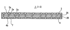
厚さ方向に連通性を有する微小孔が多数存在する多孔積層体の製造方法であって、
ハードセグメントとソフトセグメントを有する熱可塑性樹脂からなる中間層と、両側最外面に位置する樹脂組成物からなる無孔の両側外層との少なくとも3層からなる積層体を作製する工程と、
得られた積層体に超臨界状態または亜臨界状態の流体を含浸させた後に、該超臨界状態または亜臨界状態から解放して前記流体を気化させることにより前記中間層に前記微小孔を形成して多孔化する工程と、
前記中間層を多孔化した後に前記両側外層に微小孔を形成して多孔化して該微小孔を前記中間層の微小孔と連通させる工程と、
を備えることを特徴とする多孔積層体の製造方法を提供している。
The present invention, in order to solve the above problems,
A method for producing a porous laminate in which a large number of micropores having communication in the thickness direction exist,
A step of producing a laminate comprising at least three layers of an intermediate layer made of a thermoplastic resin having a hard segment and a soft segment, and a non-porous both-side outer layer made of a resin composition located on both outermost surfaces;
After the obtained laminate is impregnated with a fluid in a supercritical state or a subcritical state, the micropores are formed in the intermediate layer by releasing the supercritical state or the subcritical state and vaporizing the fluid. And making it porous,
A step of through micropores and the communication of the intermediate layers were porosified by forming a fine hole in the both outer layers after porosifying fine small holes of the intermediate layer,
A method for producing a porous laminate is provided.
好ましくは、前記中間層はフィラーを含まないポリプロピレン組成物からなる一方、前記両側外層は少なくともフィラーと熱可塑性樹脂を含有する樹脂組成物からなり、該両側外層は前記超臨界状態または亜臨界状態で含浸させた流体が該状態から解放した時に気化による孔は形成されないものとし、前記両側外層の多孔化は積層体を延伸させて前記フィラーと樹脂層との界面を剥離させて微小孔を形成している。 Preferably, the one intermediate layer is made of polypropylene pins alkylene composition without filler, said both outer layers comprises at least a resin composition containing a filler and a thermoplastic resin, the both-side outer layer the supercritical state or subcritical When the fluid impregnated in the state is released from the state, no pores are formed by vaporization, and the porous layers on both sides are formed by stretching the laminate and peeling the interface between the filler and the resin layer to form micropores. Forming.
本発明は発明者らが鋭意研究および実験を繰り返して知見した結果に基づいてなされたものである。
即ち、本発明者らは、まず、亜臨界または超臨界流体を利用して多孔化する研究・実験を行い、種々の検討を加えたが、前記した問題の表面にスキン層が生じることは回避できなかった。
そこで、本発明者らは、亜臨界または超臨界流体を利用して多孔化する層の表面に無孔層を設けて、所謂、蓋をすることにより、中間層と外側表面の無孔層とに連通する微小孔を有する多孔積層体を得ることができることを知見した。
即ち、積層体に亜臨界または超臨界流体を含浸させ、次いで、急激な圧力の低下等を発生させた時に、中間層を外側の無孔層で蓋をしているため、中間層の表面から気体が蒸散することなく、中間層の表面において過飽和状態を作り出すことができ、その結果、中間層に微小孔を作製することに成功した。その後、蓋となる無孔層を公知技術で微小孔を設けて多孔化すると、中間層の微小孔と厚さ方向に連通性を有する微小穴を有する多孔積層体を得ることができた。
The present invention has been made on the basis of results obtained by the inventors through repeated studies and experiments.
That is, the inventors first conducted research and experiments for making a porous structure using a subcritical or supercritical fluid, and made various studies, but avoiding the occurrence of a skin layer on the surface of the problem described above. could not.
Therefore, the present inventors provide a non-porous layer on the surface of the layer to be porous using a subcritical or supercritical fluid, and a so-called lid so that the intermediate layer and the non-porous layer on the outer surface It has been found that a porous laminate having micropores communicating with can be obtained.
That is, when the laminate is impregnated with a subcritical or supercritical fluid and then a sudden drop in pressure or the like is generated, the intermediate layer is covered with the outer non-porous layer. It was possible to create a supersaturated state on the surface of the intermediate layer without vaporizing the gas, and as a result, succeeded in producing micropores in the intermediate layer. Thereafter, when the nonporous layer serving as a lid was made porous by providing micropores by a known technique, a porous laminate having microholes communicating with the micropores of the intermediate layer in the thickness direction could be obtained.
本発明の製造方法では、前記したように、まず、第1工程において、ハードセグメントとソフトセグメントを有する熱可塑性樹脂からなる中間層と、両側外面に位置する樹脂組成物からなる無孔の両側外層との少なくとも3層からなる積層体を作製している。 In the production method of the present invention, as described above, first, in the first step, an intermediate layer made of a thermoplastic resin having a hard segment and a soft segment, and a non-porous both-side outer layer made of a resin composition located on both outer surfaces. And a laminate composed of at least three layers.
中間層を構成する熱可塑性樹脂としては、ハードセグメントとソフトセグメントを有すれば公知の熱可塑性樹脂を用いることができる。
ハードセグメントは層の強度を保つ役割をし、ソフトセグメントは亜臨界または超臨界流体を含浸させる役割を有する。ぞれぞれのセグメントが前記役割を確実に果たすためには、ハードセグメントの比率が5〜95質量%であり、ソフトセグメントの比率が95〜5質量%であることが好ましい。ハードセグメントの比率が5質量%未満であると、中間層が柔らかすぎて強度が保てず、また亜臨界または超臨界流体が中間層にとどまることができず脱気してしまい、中間層が多孔化できないおそれがある。一方、ソフトセグメントの比率が5質量%未満であると、亜臨界または超臨界流体の含浸量が少なくなり、十分な連通性を得ることが困難となる。
As a thermoplastic resin which comprises an intermediate | middle layer, if it has a hard segment and a soft segment, a well-known thermoplastic resin can be used.
The hard segment serves to maintain the strength of the layer, and the soft segment serves to impregnate the subcritical or supercritical fluid. In order to ensure that each segment plays the role, it is preferable that the hard segment ratio is 5 to 95 mass% and the soft segment ratio is 95 to 5 mass%. If the hard segment ratio is less than 5% by mass, the intermediate layer is too soft to maintain the strength, and the subcritical or supercritical fluid cannot remain in the intermediate layer and is degassed. There is a possibility that it cannot be made porous. On the other hand, when the soft segment ratio is less than 5% by mass, the amount of subcritical or supercritical fluid impregnated decreases, making it difficult to obtain sufficient communication.
中間層を構成する熱可塑性樹脂には、フィラーを含まないことが好ましい。これは、本発明が、単位面積あたりの質量が小さい多孔積層体を提供することを目的としているからである。 It is preferable that the thermoplastic resin constituting the intermediate layer does not contain a filler. This is because the object of the present invention is to provide a porous laminate having a small mass per unit area.
前記中間層を構成する熱可塑性樹脂のソフトセグメントとしては、例えば、ポリイソプレン、ポリブタジエン、水素添加ポリブタジエン、水素添加ポリイソプレン、アモルファスポリエチレン、ポリ塩化ビニル、ポリエーテル、エチレン−プロピレンゴム、イソブテン−イソプレンゴム、フッ素ゴムまたはシリコーンゴム等が挙げられる。ハードセグメントとしては、例えばポリスチレン、ポリエチレン、ポリプロピレン、ポリウレタン、ポリエステル、ポリアミド、ポリブチレンテレフタレートまたはフッ素樹脂等が挙げられる。 As the soft segment of the thermoplastic resin constituting the intermediate layer, for example, polyisoprene, polybutadiene, hydrogenated polybutadiene, hydrogenated polyisoprene, amorphous polyethylene, polyvinyl chloride, polyether, ethylene-propylene rubber, isobutene-isoprene rubber , Fluorine rubber or silicone rubber. Examples of the hard segment include polystyrene, polyethylene, polypropylene, polyurethane, polyester, polyamide, polybutylene terephthalate, or a fluororesin.
より具体的に、中間層を構成する熱可塑性樹脂としては、オレフィン系熱可塑性樹脂、スチレン系熱可塑性樹脂、ポリエステル系熱可塑性樹脂またはポリアミド系熱可塑性樹脂が挙げられる。
前記オレフィン系熱可塑性樹脂としては、ハードセグメントとしてポリエチレンまたはポリプロピレンを用い、ソフトセグメントとしてエチレン−プロピレンゴムまたはエチレン−プロピレン−ジエンゴム、水素添加ポリブタジエンまたは水素添加ポリイソプレンを用いたオレフィン系熱可塑性樹脂が挙げられる。
前記スチレン系熱可塑性樹脂としては、ハードセグメントとして、スチレンもしくはメチルスチレンなどのスチレン誘導体、インデンまたはビニルナフタレン等を構成単位として有する重合体、好ましくはポリスチレンを用い、ソフトセグメントとしてポリブタジエンもしくはポリイソプレンなどの共役ジエン系ポリマー、またはエチレン/ブチレン共重合体、エチレン/プロピレン共重合体もしくはポリイソブテンなどのポリオレフィン系エラストマーを用いたスチレン系熱可塑性樹脂が挙げられる。
More specifically, examples of the thermoplastic resin constituting the intermediate layer include an olefin-based thermoplastic resin, a styrene-based thermoplastic resin, a polyester-based thermoplastic resin, and a polyamide-based thermoplastic resin.
Examples of the olefinic thermoplastic resin include olefinic thermoplastic resins using polyethylene or polypropylene as a hard segment and ethylene-propylene rubber or ethylene-propylene-diene rubber, hydrogenated polybutadiene or hydrogenated polyisoprene as a soft segment. It is done.
As the styrene-based thermoplastic resin, as a hard segment, a polymer having a styrene derivative such as styrene or methylstyrene, an indene or vinyl naphthalene as a structural unit, preferably polystyrene, and a soft segment such as polybutadiene or polyisoprene. A styrene-based thermoplastic resin using a conjugated diene-based polymer or a polyolefin-based elastomer such as an ethylene / butylene copolymer, an ethylene / propylene copolymer, or polyisobutene can be given.
前記ポリエステル系熱可塑性樹脂としては、ハードセグメントとして芳香族ポリエステル、脂環族ポリエステルあるいはそれらの誘導体あるいはそれらの混合物などを用い、ソフトセグメントとしては、ポリテトラメチレングリコールやポリ(エチレン/プロピレン)ブロックポリグリコールなどのポリアルキレングリコールなどを用いたポリエステル系熱可塑性樹脂が挙げられる。
前記ポリアミド系熱可塑性樹脂としては、ハードセグメントとして、ポリアミド6、ポリアミド66、ポリアミド610、ポリアミド612、ポリアミド11、ポリアミド12等のポリアミドまたはこれらの共重合体を用い、ソフトセグメントとしてポリテトラメチレングリコールやポリ(エチレン/プロピレン)ブロックポリグリコールなどのポリアルキレングリコールなどを用いたポリアミド系熱可塑性樹脂が挙げられる。
As the polyester-based thermoplastic resin, an aromatic polyester, an alicyclic polyester or a derivative thereof, or a mixture thereof is used as a hard segment, and a polytetramethylene glycol or poly (ethylene / propylene) block poly is used as a soft segment. And polyester-based thermoplastic resins using polyalkylene glycols such as glycols.
As the polyamide-based thermoplastic resin, polyamides such as polyamide 6, polyamide 66, polyamide 610, polyamide 612, polyamide 11 and polyamide 12 or copolymers thereof are used as hard segments, and polytetramethylene glycol or the like as soft segments. Examples thereof include polyamide-based thermoplastic resins using polyalkylene glycol such as poly (ethylene / propylene) block polyglycol.
本発明において中間層を構成する熱可塑性樹脂としてはオレフィン系熱可塑性樹脂が好ましい。
オレフィン系熱可塑性樹脂を構成するハードセグメントとしては、
・エチレンの単独重合体樹脂、エチレンを主成分とし炭素数3以上のα−オレフィンを副成分とする共重合体樹脂;
・プロピレンの単独重合体樹脂、プロピレンを主成分としこれとエチレンもしくは炭素数4以上のα−オレフィンとの共重合体樹脂;
・1−ブテンの単独重合体樹脂、1−ブテンを主成分としこれとエチレン、プロピレンもしくは炭素数5以上のα−オレフィンとの共重合体樹脂;
・4−メチル−1−ペンテンの単独重合体樹脂、4−メチル−1−ペンテンを主成分とし、これとエチレン、プロピレン、1−ブテンもしくは炭素数6以上のα−オレフィンとの共重合体樹脂;
・上記樹脂の変性物
が挙げられる。これら2種類以上が混合されていても良い。
In the present invention, the thermoplastic resin constituting the intermediate layer is preferably an olefinic thermoplastic resin.
As a hard segment constituting the olefin thermoplastic resin,
A homopolymer resin of ethylene, a copolymer resin having ethylene as a main component and an α-olefin having 3 or more carbon atoms as a minor component;
A homopolymer resin of propylene, a copolymer resin of propylene as a main component and ethylene or an α-olefin having 4 or more carbon atoms;
1-butene homopolymer resin, a copolymer resin of 1-butene as a main component and ethylene, propylene or an α-olefin having 5 or more carbon atoms;
· Homopolymer resin of 4-methyl-1-pentene, copolymer resin of 4-methyl-1-pentene as a main component and ethylene, propylene, 1-butene or α-olefin having 6 or more carbon atoms ;
・ Modified products of the above resins. Two or more of these may be mixed.
オレフィン系熱可塑性樹脂を構成するソフトセグメントとしては、例えばジエン系ゴム、水素添加ジエン系ゴム、オレフィンエラストマー等が挙げられる。
ジエン系ゴムとしては、イソプレンゴム、ブタジエンゴム、ブチルゴム、プロピレン−ブタジエンゴム、アクリロニトリル−ブタジエンゴム、アクリロニトリル−イソプレンゴム、スチレン−ブタジエンゴム等が挙げられる。
水素添加ジエン系ゴムは、ジエン系ゴム分子の二重結合の少なくとも一部分に水素原子を付加させてなるものである。
オレフィンエラストマーは、2種類または3種類以上のオレフィンと共重合しうるポリエンを少なくとも1種加えた弾性共重合体であり、オレフィンとしてはエチレンもしくはプロピレン等のα−オレフィン等が使用され、ポリエンとしては1,4−ヘキサジエン、環状ジエン、ノルボルネン等が使用される。好ましいオレフィンエラストマーとしては、例えばエチレン−プロピレン共重合体ゴム、エチレン−プロピレン−ジエンゴム、エチレン−ブタジエン共重合体ゴム等が挙げられる。
Examples of the soft segment constituting the olefin-based thermoplastic resin include diene rubber, hydrogenated diene rubber, olefin elastomer, and the like.
Examples of the diene rubber include isoprene rubber, butadiene rubber, butyl rubber, propylene-butadiene rubber, acrylonitrile-butadiene rubber, acrylonitrile-isoprene rubber, and styrene-butadiene rubber.
The hydrogenated diene rubber is obtained by adding a hydrogen atom to at least a part of a double bond of a diene rubber molecule.
The olefin elastomer is an elastic copolymer obtained by adding at least one polyene copolymerizable with two or three or more olefins. As the olefin, an α-olefin such as ethylene or propylene is used. 1,4-hexadiene, cyclic diene, norbornene and the like are used. Preferred olefin elastomers include, for example, ethylene-propylene copolymer rubber, ethylene-propylene-diene rubber, ethylene-butadiene copolymer rubber and the like.
本発明の中間層を構成する樹脂としては、オレフィン系熱可塑性樹脂のなかでも、ハードセグメントとしてプロピレン系樹脂を有するオレフィン系熱可塑性樹脂がより好ましい。特に、ハードセグメントとしてプロピレン系樹脂を有し、ソフトセグメントとしてエチレン−プロピレンゴムを5〜95質量%の割合で有するオレフィン系熱可塑性樹脂が好ましい。
ハードセグメントとしてのプロピレン系樹脂にはホモポリマーとコポリマーがあり、更にコポリマーにはランダムコポリマーとブロックコポリマーがある。ホモポリマーはプロピレン単独重合体であり、アイソタクティックないしはシンジオタクティックおよび種々の程度の立体規則性を示すポリプロピレンである。一方、コポリマーとしては、プロピレンを主成分とし、これとエチレン、1−ブテン、1−ペンテン、1−ヘキセン、4−メチル−1−ペンテン、1−ヘプテン、1−オクテンもしくは1−デセン等のα−オレフィンとの共重合体が使用される。この共重合体は、2元系でも3元系でも4元系でもよく、またランダム共重合体でもブロック共重合体であってもよい。
プロピレン系樹脂には、プロピレン系単独重合体よりも融点が低い樹脂を混合することもできる。そのような融点が低い樹脂として、高密度あるいは低密度ポリエチレン等を例示することができ、その配合量は2〜50質量%であることが好ましい。
The resin constituting the intermediate layer of the present invention is more preferably an olefin thermoplastic resin having a propylene resin as a hard segment among olefin thermoplastic resins. In particular, an olefin-based thermoplastic resin having a propylene-based resin as a hard segment and an ethylene-propylene rubber in a proportion of 5 to 95% by mass as a soft segment is preferable.
The propylene resin as the hard segment includes homopolymers and copolymers, and the copolymers include random copolymers and block copolymers. Homopolymers are propylene homopolymers, which are isotactic or syndiotactic and polypropylene exhibiting various degrees of stereoregularity. On the other hand, as a copolymer, propylene is a main component, and this and α such as ethylene, 1-butene, 1-pentene, 1-hexene, 4-methyl-1-pentene, 1-heptene, 1-octene or 1-decene. -Copolymers with olefins are used. This copolymer may be a binary system, a ternary system, or a quaternary system, and may be a random copolymer or a block copolymer.
The propylene resin may be mixed with a resin having a lower melting point than that of the propylene homopolymer. Examples of such a resin having a low melting point include high-density or low-density polyethylene , and the blending amount is preferably 2 to 50% by mass.
ソフトセグメントとしてのエチレン−プロピレンゴムには、エチレンとプロピレンの二元共重合体と、さらに第3成分としての非共役ジエンモノマーを少量含む三元重合体とがあるが、本発明においてはいずれを用いてもよい。前記非共役ジエンモノマーとしては、ジシクロペンタジエン、エチリデンノルボルネンまたはヘキサジエンなどが挙げられる。
エチレン−プロピレンゴムとしては、ゴム全体に対するエチレン含有率が7〜80質量%であるエチレン−プロピレンゴムが好ましく、10〜60質量%であるエチレン−プロピレンゴムがより好ましい。
エチレン−プロピレンゴムの含有量またはエチレン−プロピレンゴム中のエチレン含有率を調整することにより中間層を構成する樹脂組成物全体に対するエチレン含有率を5〜95質量%とすることが好ましい。
The ethylene-propylene rubber as a soft segment includes a binary copolymer of ethylene and propylene and a terpolymer containing a small amount of a non-conjugated diene monomer as a third component. It may be used. Examples of the non-conjugated diene monomer include dicyclopentadiene, ethylidene norbornene, and hexadiene.
As the ethylene-propylene rubber, an ethylene-propylene rubber having an ethylene content of 7 to 80% by mass relative to the whole rubber is preferable, and an ethylene-propylene rubber having 10 to 60% by mass is more preferable.
By adjusting the ethylene-propylene rubber content or the ethylene content in the ethylene-propylene rubber, the ethylene content relative to the entire resin composition constituting the intermediate layer is preferably 5 to 95 mass%.
上記中間層の樹脂の製造方法による種類分けとしては、ハードセグメントを構成するプロピレン系樹脂にソフトセグメントを構成するエチレン−プロピレンゴム等の軟質成分を二軸押出機のような混練機を用いてブレンドするコンパウンド型ポリマーと、エチレン等とプロピレンを直接重合させる重合型ポリマーが存在する。
ソフトセグメントを構成するエチレン−プロピレンゴム等の軟質成分の分散性の観点から、重合型ポリマーを用いる方が好ましい。
As for the classification by the method for producing the resin of the intermediate layer, the propylene resin constituting the hard segment is blended with a soft component such as ethylene-propylene rubber constituting the soft segment using a kneader such as a twin screw extruder. There are compound type polymers and polymerized polymers that directly polymerize ethylene and propylene.
From the viewpoint of dispersibility of soft components such as ethylene-propylene rubber constituting the soft segment, it is preferable to use a polymerization type polymer.
更にソフトセグメントの含有率を上げる方法として、市販のプロピレンコポリマーにエチレンプロピレンゴム等の軟質成分をブレンドする方法もある。この場合は、二軸押出機等の混練機を使うと簡単にソフトセグメントの含有率を上げることができる。
同様にプロピレンホモポリマーにエチレンプロピレンゴムやポリエチレン等を二軸押出機等の混練機を使ってブレンドすることにより、好ましいソフトセグメントの含有率をもつオレフィン系熱可塑性樹脂を得ることができる。
Further, as a method for increasing the content of the soft segment, there is a method of blending a commercially available propylene copolymer with a soft component such as ethylene propylene rubber. In this case, the content of the soft segment can be easily increased by using a kneader such as a twin screw extruder.
Similarly, an olefinic thermoplastic resin having a preferable soft segment content can be obtained by blending propylene homopolymer with ethylene propylene rubber or polyethylene using a kneader such as a twin screw extruder.
さらに、本発明の目的や中間層の特性を損なわない程度の範囲であれば、中間層を構成する熱可塑性樹脂に一般に樹脂組成物に配合される添加剤、例えば、酸化防止剤、熱安定剤、光安定剤、紫外線吸収剤、中和剤、防曇剤、アンチブロッキング剤、帯電防止剤、スリップ剤または着色剤等を配合してもよい。 Furthermore, additives that are generally blended into the resin composition in the thermoplastic resin constituting the intermediate layer, such as antioxidants and thermal stabilizers, are within a range that does not impair the purpose of the present invention and the properties of the intermediate layer. , A light stabilizer, an ultraviolet absorber, a neutralizer, an antifogging agent, an antiblocking agent, an antistatic agent, a slip agent, a colorant, and the like may be blended.
上述した中間層を挟んで両側の最外面に位置させる両側外層は、孔のない無孔の樹脂組成物からなる層としている。該両側外層は前記中間層を構成する熱可塑性樹脂と相溶性を有する熱可塑性樹脂から構成されていることがより好ましい。
これは、両側外層を構成する熱可塑性樹脂と中間層を構成する熱可塑性樹脂とが相溶性を示さないと、亜臨界または超臨界流体を含浸させ、その後、急激な圧力の低下等を発生させても、両側外層と中間層の界面では過飽和状態になりにくく、界面から気体が拡散・蒸発により放出されるため、外層と中間層に連通する孔を形成できなくなる可能性があるからである。
The outer side layers located on the outermost surfaces on both sides of the intermediate layer described above are layers made of a non-porous resin composition having no holes. More preferably, the outer layers on both sides are made of a thermoplastic resin compatible with the thermoplastic resin constituting the intermediate layer.
If the thermoplastic resin constituting the outer layer on both sides and the thermoplastic resin constituting the intermediate layer do not have compatibility, the subcritical or supercritical fluid is impregnated, and then a sudden pressure drop occurs. However, it is difficult to form a supersaturated state at the interface between the outer layers on both sides and the intermediate layer, and gas is released from the interface by diffusion / evaporation, which may make it impossible to form a hole communicating with the outer layer and the intermediate layer.
前記両側外層を構成する熱可塑性樹脂としては具体的にはポリオレフィン樹脂、フッ素樹脂、ポリスチレン、ABS樹脂、塩化ビニル樹脂、酢酸ビニル樹脂、アクリル樹脂、ポリアミド樹脂、アセタール樹脂、ポリカーボネート等の熱可塑性樹脂が挙げられる。
熱可塑性樹脂としてはポリオレフィン樹脂を用いることが好ましい。電池用セパレーターとして使用する場合は、電解液との安定性の観点から特にポリオレフィン樹脂を用いることが好ましい。ポリオレフィン樹脂としては、例えば、エチレン、プロピレン、1−ブテン、1−へキセン、1−オクテンもしくは1−デセン等のモノオレフイン重合体、またはエチレン、プロピレン、1−ブテン、1−ヘキセン、1−オクテンもしくは1−デセンと4−メチル−1−ペンテンもしくは酢酸ビニル等の他のモノマーとの共重合体等を主成分とするものが挙げられる。なかでも、ポリプロピレン、高密度ポリエチレン、低密度ポリエチレン、線状低密度ポリエチレン、ポリブテン、プロピレンエチレンブロック共重合体、プロピレンエチレンランダム共重合体等が好ましい。
Specific examples of the thermoplastic resin constituting the both outer layers include thermoplastic resins such as polyolefin resin, fluorine resin, polystyrene, ABS resin, vinyl chloride resin, vinyl acetate resin, acrylic resin, polyamide resin, acetal resin, and polycarbonate. Can be mentioned.
A polyolefin resin is preferably used as the thermoplastic resin. When used as a battery separator, it is particularly preferable to use a polyolefin resin from the viewpoint of stability with the electrolytic solution. Examples of the polyolefin resin include monoolefin polymers such as ethylene, propylene, 1-butene, 1-hexene, 1-octene and 1-decene, or ethylene, propylene, 1-butene, 1-hexene and 1-octene. Or what has as a main component the copolymer of 1-decene, other monomers, such as 4-methyl- 1-pentene or vinyl acetate, etc. is mentioned. Among these, polypropylene, high density polyethylene, low density polyethylene, linear low density polyethylene, polybutene, propylene ethylene block copolymer, propylene ethylene random copolymer, and the like are preferable.
前記熱可塑性樹脂のうち、ポリエチレンを主とし、具体的には、ポリエチレンを該熱可塑性樹脂100質量部中に少なくとも50質量部、好ましくは80質量部以上、さらに好ましくは95質量部以上含むことが好ましい。
ポリエチレンはポリエチレンホモポリマーまたはポリエチレンコポリマーのいずれであっても良いが、ポリエチレンホモポリマーであることが好ましい。前記ポリエチレンコポリマーとしてはα−オレフィンコモノマー含量が2モル%以下のポリエチレンコポリマーが好ましい。なお、前記α−オレフィンコモノマーの種類には特に制限はない。
Among the thermoplastic resins, polyethylene is mainly used. Specifically, polyethylene is contained in 100 parts by mass of the thermoplastic resin at least 50 parts by mass, preferably 80 parts by mass or more, more preferably 95 parts by mass or more. preferable.
The polyethylene may be either a polyethylene homopolymer or a polyethylene copolymer, but is preferably a polyethylene homopolymer. The polyethylene copolymer is preferably a polyethylene copolymer having an α-olefin comonomer content of 2 mol% or less. The kind of the α-olefin comonomer is not particularly limited.
ポリエチレンは、密度が0.92g/cm3以上であることが好ましい。密度を0.92g/cm3以上としているのは、層の厚さを5〜40μm程度の薄肉としても容易に裂けない所要の強度および剛性を付与するためである。ポリエチレンの密度はより好ましくは0.94g/cm3以上であり、上限は特に限定されないが、0.97g/cm3程度のものが好適である。
また、前記ポリエチレンはメルトフローレートが10g/10分以下、好ましくは1g/10分以下である。メルトフローレートが10g/10分より大きいと多孔積層体の強度が低下する場合がある。
The polyethylene preferably has a density of 0.92 g / cm 3 or more. The reason why the density is 0.92 g / cm 3 or more is to provide required strength and rigidity that do not easily tear even when the layer thickness is about 5 to 40 μm. The density of polyethylene is more preferably 0.94 g / cm 3 or more, and the upper limit is not particularly limited, but a density of about 0.97 g / cm 3 is suitable.
The polyethylene has a melt flow rate of 10 g / 10 min or less, preferably 1 g / 10 min or less. If the melt flow rate is greater than 10 g / 10 min, the strength of the porous laminate may be reduced.
ポリエチレンの重合方法として、一段重合、二段重合もしくはそれ以上の多段重合等があり、いずれの方法のポリエチレンも使用可能である。また、ポリエチレンの重合触媒には特に制限はなく、チーグラー型触媒、フィリップス型触媒、カミンスキー型触媒等いずれのものでも良い。 As a method for polymerizing polyethylene, there are one-stage polymerization, two-stage polymerization, or more multistage polymerization, and any method of polyethylene can be used. The polymerization catalyst for polyethylene is not particularly limited, and any of a Ziegler type catalyst, a Philips type catalyst, a Kaminsky type catalyst or the like may be used.
前記両側外層は、上述したポリエチレンを単独で用いても良いが、一般的な熱可塑性樹脂をポリエチレンに混合しても良い。
ポリエチレンに混合できる熱可塑性樹脂として、具体的にはポリエチレン以外のポリオレフィン樹脂、フッ素樹脂、ポリスチレン、酢酸ビニル樹脂、アクリル樹脂、ポリアミド樹脂、アセタール樹脂またはポリカーボネート等の熱可塑性樹脂が挙げられる。好ましくはポリプロピレン、ポリブテン、プロピレンエチレンブロック共重合体、プロピレンエチレンランダム共重合体等が挙げられる。ポリエチレンに混合できる熱可塑性樹脂は融点が140℃以上であることが好ましい。
このように、ポリエチレンに他の熱可塑性樹脂を混合する場合は、当該他の熱可塑性樹脂の配合量はポリエチレン100質量部に対して、1〜100質量部、好ましくは1〜50質量部としている。
For the outer side layers, the above-described polyethylene may be used alone, but a general thermoplastic resin may be mixed with polyethylene.
Specific examples of the thermoplastic resin that can be mixed with polyethylene include thermoplastic resins such as polyolefin resins other than polyethylene, fluorine resins, polystyrene, vinyl acetate resins, acrylic resins, polyamide resins, acetal resins, and polycarbonates. Preferably, polypropylene, polybutene, propylene ethylene block copolymer, propylene ethylene random copolymer and the like can be mentioned. The thermoplastic resin that can be mixed with polyethylene preferably has a melting point of 140 ° C. or higher.
Thus, when mixing other thermoplastic resin with polyethylene, the compounding quantity of the said other thermoplastic resin is 1-100 mass parts with respect to 100 mass parts of polyethylene, Preferably it is 1-50 mass parts. .
前記両側外層を構成する組成物には、本発明の目的および最外層の特性を損なわない程度の範囲で、一般に樹脂組成物に配合される添加剤を配合してもよい。添加剤としては、中間層に配合することのできる添加剤と同じ添加剤が例示できる。これら添加剤の配合量は、最外層を構成する熱可塑性樹脂100質量部に対し1〜30質量部程度であることが好ましい。 In the composition constituting the both-side outer layers, additives generally blended in the resin composition may be blended within a range that does not impair the purpose of the present invention and the characteristics of the outermost layer. As an additive, the same additive as the additive which can be mix | blended with an intermediate | middle layer can be illustrated. It is preferable that the compounding quantity of these additives is about 1-30 mass parts with respect to 100 mass parts of thermoplastic resins which comprise an outermost layer.
また、前記両側外層を構成する組成物には、下記に詳述する第3工程で多孔化のために延伸法を採用する場合には、必要な成分であるフィラーを配合している。
第3工程では、延伸法により両側外層を多孔化することが好ましく、その場合には、樹脂にフィラーを配合しておき、樹脂とフィラーとの界面を剥離させて多孔化している。
Moreover, the filler which is a required component is mix | blended with the composition which comprises the said both-sides outer layer, when employ | adopting the extending | stretching method for porosity in the 3rd process explained in full detail below.
In the third step, it is preferable to make the outer layers on both sides porous by a stretching method. In that case, a filler is blended in the resin, and the interface between the resin and the filler is peeled to make it porous.
前記フィラーとしては、無機フィラーおよび有機フィラーの何れのフィラーも使用でき、1種または2種以上を組み合わせて使用できる。
無機フィラーとしては、炭酸カルシウム、炭酸マグネシウム、炭酸バリウムなどの炭酸塩;硫酸カルシウム、硫酸マグネシウム、硫酸バリウムなどの硫酸塩;塩化ナトリウム、塩化カルシウム、塩化マグネシウムなどの塩化物;酸化カルシウム、酸化マグネシウム、酸化亜鉛、酸化チタン、シリカなどの酸化物;タルク、クレー、マイカなどのケイ酸塩等が挙げられる。これらの中でも、硫酸バリウムが好ましい。
As said filler, any filler of an inorganic filler and an organic filler can be used, and it can use 1 type or in combination of 2 or more types.
Examples of inorganic fillers include carbonates such as calcium carbonate, magnesium carbonate and barium carbonate; sulfates such as calcium sulfate, magnesium sulfate and barium sulfate; chlorides such as sodium chloride, calcium chloride and magnesium chloride; calcium oxide, magnesium oxide, Examples thereof include oxides such as zinc oxide, titanium oxide and silica; silicates such as talc, clay and mica. Among these, barium sulfate is preferable.
無機フィラーは樹脂中の分散性向上のため、表面処理剤で無機フィラーの表面を被覆して疎水化してもよい。この表面処理剤としては、例えばステアリン酸またはラウリル酸等の高級脂肪酸またはそれらの金属塩を挙げることができる。 In order to improve the dispersibility in the resin, the inorganic filler may be hydrophobized by coating the surface of the inorganic filler with a surface treatment agent. Examples of the surface treatment agent include higher fatty acids such as stearic acid or lauric acid, or metal salts thereof.
有機フィラーとしては、延伸温度においてフィラーが溶融しないように、最外層を構成する熱可塑性樹脂の融点よりも高い融点を有する樹脂粒子が好ましく、ゲル分が4〜10%程度の架橋した樹脂粒子がさらに好ましい。
該有機フィラーとしては、超高分子量ポリエチレン、ポリスチレン、ポリメチルメタクリレート、ポリカーボネート、ポリエチレンテレフタレート、ポリブチレンテレフタレート、ポリフェニレンサルファイド、ポリスルホン、ポリエーテルスルホン、ポリエーテルエーテルケトン、ポリテトラフルオロエチレン、ポリイミド、ポリエーテルイミド、メラミン、ベンゾグアナミンなどの熱可塑性樹脂および熱硬化性樹脂が挙げられる。これらの中でも、特に架橋させたポリスチレンなどが好ましい。
The organic filler is preferably resin particles having a melting point higher than the melting point of the thermoplastic resin constituting the outermost layer so that the filler does not melt at the stretching temperature, and crosslinked resin particles having a gel content of about 4 to 10%. Further preferred.
Examples of the organic filler include ultra high molecular weight polyethylene, polystyrene, polymethyl methacrylate, polycarbonate, polyethylene terephthalate, polybutylene terephthalate, polyphenylene sulfide, polysulfone, polyethersulfone, polyetheretherketone, polytetrafluoroethylene, polyimide, polyetherimide. , Thermoplastic resins such as melamine and benzoguanamine, and thermosetting resins. Among these, cross-linked polystyrene and the like are particularly preferable.
前記フィラーの平均粒径としては0.01〜25μm程度、好ましくは0.05〜7μmであり、更に好ましくは0.1〜5μmである。平均粒径が0.01μm未満の場合には、フィラー同士の凝集により分散性が低下して延伸むらを引き起こし、多孔化が困難になりやすい。一方、平均粒径が25μmを超えると、表面の凹凸を大きくすることは可能となるが、それと同時に表面の孔径の大きな不均一を発生させる可能性が高くなるので好ましくない。 The average particle size of the filler is about 0.01 to 25 μm, preferably 0.05 to 7 μm, and more preferably 0.1 to 5 μm. When the average particle size is less than 0.01 μm, the dispersibility is lowered due to aggregation of fillers, causing unevenness of stretching, and it is difficult to obtain a porous structure. On the other hand, if the average particle diameter exceeds 25 μm, it is possible to increase the surface irregularities, but at the same time, the possibility of generating large nonuniformities in the surface pore diameter increases, which is not preferable.
フィラーの配合量はフィラーの種類により異なるので一概にはいえないが、両側外層を構成する熱可塑性樹脂100質量部に対し25〜400質量部であることが好ましく、50〜300質量部であることがより好ましい。フィラーの配合量が前記樹脂100質量部に対し25質量部未満の場合には、目的とする良好な透気性が発現されにくくなり、外観や風合いも悪くなりやすい。また、フィラーの配合量が400質量部を超えると、積層体作製の際に樹脂焼けなど工程上の不具合を起こしやすくなるだけでなく、多孔積層体の強度も大幅に低下する。 Since the blending amount of the filler varies depending on the type of filler, it cannot be generally stated, but it is preferably 25 to 400 parts by mass, and 50 to 300 parts by mass with respect to 100 parts by mass of the thermoplastic resin constituting the outer layers on both sides. Is more preferable. When the blending amount of the filler is less than 25 parts by mass with respect to 100 parts by mass of the resin, the desired good air permeability is hardly expressed, and the appearance and texture are liable to deteriorate. Moreover, when the compounding quantity of a filler exceeds 400 mass parts, it will become easy to raise | generate the malfunction on processes, such as resin baking, at the time of laminated body preparation, and the intensity | strength of a porous laminated body will also fall significantly.
さらに、前記両側外層には、樹脂中へのフィラーの分散性を高める目的で可塑剤を配合することが好ましい。
前記可塑剤としては、エステル化合物、アミド化合物、アルコール化合物、アミン塩、アミン化合物(ただしアミン塩は除く)、エポキシ化合物、エーテル化合物、鉱油、油脂、パラフィンワックス、液状シリコーン、フッ素オイル、液状ポリエーテル類、液状ポリブテン類、液状ポリブタジエン類、長鎖脂肪酸、カルボン酸塩、カルボン酸化合物(ただしカルボン酸塩は除く)、スルホン酸塩、スルホン化合物(ただしスルホン酸塩を除く)、フッ素系化合物等が挙げられる。
具体的にはプラスチック配合剤(株式会社 大成社発行 昭和62年11月30日 第2版発行)P31〜P64、P83、P97〜P100、P154〜P158、P178〜P182、P271〜P275、P283〜294に記載の化合物等が挙げられる。より具体的には、P29〜64の可塑剤の項目に記載され、P49からP50の表4と、P52〜P54の表6に列挙されている可塑剤(TCP,TOP,PS,ESBO等)が使用可能である。また新・界面活性剤入門(三洋化成工業株式会社発行 1992年8月 第3版発行)に挙げられている界面活性剤類の化合物も可塑剤として好適に使用できる。
Furthermore, it is preferable to add a plasticizer to the both outer layers for the purpose of enhancing the dispersibility of the filler in the resin.
Examples of the plasticizer include ester compounds, amide compounds, alcohol compounds, amine salts, amine compounds (excluding amine salts), epoxy compounds, ether compounds, mineral oil, fats and oils, paraffin wax, liquid silicone, fluorine oil, and liquid polyether. , Liquid polybutenes, liquid polybutadienes, long chain fatty acids, carboxylates, carboxylic acid compounds (excluding carboxylates), sulfonates, sulfone compounds (excluding sulfonates), fluorine compounds, etc. Can be mentioned.
Specifically, plastic compounding agents (published by Taiseisha Co., Ltd., November 30, 1987, second edition) P31 to P64, P83, P97 to P100, P154 to P158, P178 to P182, P271 to P275, P283 to 294 And the like. More specifically, the plasticizers (TCP, TOP, PS, ESBO, etc.) described in the items of plasticizers P29 to P64 and listed in Tables 4 to 49 and P6 to P54 are listed. It can be used. Further, the surfactant compounds listed in the new introduction to surfactants (published by Sanyo Kasei Kogyo Co., Ltd., August 1992, third edition) can also be suitably used as plasticizers.
前記エステル化合物としては、テトラグリセリントリステアレート、グリセリントリステアレート、ステアリルステアレート、グリセリンモノステアレート、ソルビタンモノステアレート、エチレンカーボネート、ジステアリルカーボネートまたはジオクチルナフタレート等が挙げられる。
前記アミド化合物としては、エチレンビスステアリン酸アミドまたはヘキサメチレンビスステアリン酸アミドなどが挙げられる。
前記アルコール化合物としては、ステアリルアルコール、オレイルアルコールまたはドデシルフェノールなどが挙げられる。
前記アミン塩としては、ステアリルジメチルベタインまたはラウリルトリメチルアンモニウムクロリドなどが挙げられる。
前記アミン化合物としては、ジヒドロジエチルステアリルアミンまたはラウリルアミンなどが挙げられる。
前記エポキシ化合物としては、エポキシ大豆油などが挙げられる。
前記エーテル化合物としては、トリエチレングリコールなどが挙げられる。
前記鉱油としては、灯油またはナフテン油などが挙げられる。
前記油脂としては、ひまし油もしくは硬化ひまし油またはこれらの誘導体が挙げられる。
前記脂肪酸としては、ステアリン酸またはカプロン酸などが挙げられる。
前記カルボン酸塩としては、ステアリン酸カルシウムまたはオレイン酸ナトリウムなどが挙げられる。
前記カルボン酸化合物としては、ステアリン酸もしくはオレイン酸、またはこれらのエステル体などの誘導体(ただし塩は除く。)などが挙げられる。
前記スルホン酸塩としては、ドデシルベンゼンスルホン酸ナトリウムなどが挙げられる。
前記スルホン化合物としては、スルホン結合を有する化合物(ただし塩は除く。)であればよく、スルホランまたはジプロピルスルホン酸などが挙げられる。
Examples of the ester compound include tetraglycerin tristearate, glycerin tristearate, stearyl stearate, glycerin monostearate, sorbitan monostearate, ethylene carbonate, distearyl carbonate or dioctyl naphthalate.
Examples of the amide compound include ethylene bis stearamide and hexamethylene bis stearamide.
Examples of the alcohol compound include stearyl alcohol, oleyl alcohol, and dodecylphenol.
Examples of the amine salt include stearyl dimethyl betaine or lauryl trimethyl ammonium chloride.
Examples of the amine compound include dihydrodiethyl stearylamine and laurylamine.
Examples of the epoxy compound include epoxy soybean oil.
Examples of the ether compound include triethylene glycol.
Examples of the mineral oil include kerosene and naphthenic oil.
Examples of the oil include castor oil, hardened castor oil, and derivatives thereof.
Examples of the fatty acid include stearic acid and caproic acid.
Examples of the carboxylate include calcium stearate and sodium oleate.
Examples of the carboxylic acid compound include stearic acid, oleic acid, and derivatives thereof (excluding salts).
Examples of the sulfonate include sodium dodecylbenzenesulfonate.
The sulfone compound may be a compound having a sulfone bond (excluding a salt), and examples thereof include sulfolane and dipropylsulfonic acid.
前記可塑剤のうち、硬化ひまし油が配合されていることが好ましい。
硬化ひまし油とは、リシノール酸の二重結合部を水素添加し、飽和脂肪酸とした12−ヒドロキシオクタデカン酸を主成分とする脂肪酸混合物とグリセリンとのエステルのことである。このエステルにはモノエステル、ジエステルおよびトリエステルがあるが、これらの単独物であっても、また混合物であってもよい。なかでも、トリエステルを主成分とするものが好ましい。
また、前記脂肪酸混合物に含まれる12−ヒドロキシオクタデカン酸以外の他の脂肪酸としては、炭素数12〜22程度のヘキサデカン酸もしくはオクタデカン酸等が挙げられる。かかる硬化ヒマシ油は、工業的には不乾性油であるヒマシ油に水素添加することにより製造される。
Of the plasticizer, hardened castor oil is preferably blended.
Hardened castor oil is an ester of a fatty acid mixture containing 12-hydroxyoctadecanoic acid as a main component and hydrogenated at a double bond portion of ricinoleic acid to form a saturated fatty acid. These esters include monoesters, diesters and triesters, which may be used alone or as a mixture. Especially, what has triester as a main component is preferable.
Examples of fatty acids other than 12-hydroxyoctadecanoic acid contained in the fatty acid mixture include hexadecanoic acid or octadecanoic acid having about 12 to 22 carbon atoms. Such hydrogenated castor oil is industrially produced by hydrogenating castor oil, which is a non-drying oil.
可塑剤の配合量は、両側外層を構成する熱可塑性樹脂100質量部に対し、1〜30質量部程度であることが好ましく、1〜15質量部であることがより好ましく、2〜10質量部であることがとくに好ましい。可塑剤の配合量が1質量部未満の場合には、外観や風合いが悪くなりやすく、また最外層を延伸により多孔化する場合には目的とする良好な延伸性が発現されにくくなる。また、可塑剤の配合量が30質量部を超えると、積層体作製の際に樹脂焼けなど工程上の不具合を起こしやすくなる。 The blending amount of the plasticizer is preferably about 1 to 30 parts by mass, more preferably 1 to 15 parts by mass, with respect to 100 parts by mass of the thermoplastic resin constituting both outer layers. Is particularly preferred. When the blending amount of the plasticizer is less than 1 part by mass, the appearance and the texture are liable to deteriorate, and when the outermost layer is made porous by stretching, the desired good stretchability is hardly expressed. Moreover, when the compounding quantity of a plasticizer exceeds 30 mass parts, it will become easy to raise | generate the malfunction on processes, such as resin burning, at the time of laminated body preparation.
本発明の第1工程において作製される積層体は、上述した中間層と当該中間層を挟んで両側の最外面に位置する2つの無孔の両側外層の少なくとも3層からなれば、特にその構造は限定されない。
例えば、中間層が組成の異なる複数層から構成されていてもよいし、最外層の一方または両方が組成の異なる複数層から構成されていてもよい。また、中間層の間に最外層と同じ組成を有する無孔層が挟まれている5層構造としていてもよい。その場合、組成の異なる2種類の中間層が積層され、連続してフィラーを含有しない層でもよい。
If the laminate produced in the first step of the present invention comprises at least three layers of the above-mentioned intermediate layer and two non-porous outer layers located on the outermost surfaces on both sides with the intermediate layer interposed therebetween, the structure in particular Is not limited.
For example, the intermediate layer may be composed of a plurality of layers having different compositions, or one or both of the outermost layers may be composed of a plurality of layers having different compositions. Further, a five-layer structure in which a non-porous layer having the same composition as the outermost layer is sandwiched between intermediate layers may be employed. In that case, two types of intermediate layers having different compositions may be laminated, and a layer that does not contain a filler continuously may be used.
さらに、両側外層の組成または構造は同一であってもよいし、異なっていても良い。例えば、2つの両側外層のそれぞれが異なる物質と接触する場合は、それぞれの特性に合わせた熱可塑性樹脂の選定が必要となる。例えば、一方の層が水と接触し他方の層が有機溶媒と接触する場合は、水と接触する最外層を構成する熱可塑性樹脂を耐水性のあるポリスチレンとし、有機溶媒と接触する最外層を構成する熱可塑性樹脂を耐有機溶媒性の高いポリプロピレンとすることができる。
両側外層に配合するフィラーに関しても同様で、例えば、両側外層がそれぞれ中性と酸性の液体に接触する場合、中性の液体に接触する外層では炭酸カルシウムを配合し、酸性の液体に接触する外層においては硫酸バリウムを配合することができる。
Furthermore, the composition or structure of the outer layers on both sides may be the same or different. For example, when each of the two outer layers is in contact with a different substance, it is necessary to select a thermoplastic resin suitable for each characteristic. For example, when one layer is in contact with water and the other layer is in contact with an organic solvent, the thermoplastic resin constituting the outermost layer in contact with water is water-resistant polystyrene, and the outermost layer in contact with the organic solvent is The thermoplastic resin to be formed can be polypropylene having a high organic solvent resistance.
The same applies to the filler blended in the outer layers on both sides. For example, when both outer layers are in contact with neutral and acidic liquids, the outer layer in contact with the neutral liquid is blended with calcium carbonate and is in contact with the acidic liquid. Can contain barium sulfate.
本発明の第1工程において作製される積層体においては、第3工程において延伸処理した場合に、該延伸処理後における全層の厚みtに対する両最外層の厚みの合計toの割合tr(=to/t)が0.05〜0.95、好ましくは0.10〜0.90、さらに好ましくは0.15〜0.80となるように調整している。
trが0.05より小さければ、最外層の実質的な厚みが極端に薄くなってしまい、結果的に最外表面の多孔構造が極端に不均一になりやすい。また、最外層の厚みが極端に薄いと蓋の役割を果たさない。すなわち、超臨界状態または亜臨界状態の流体を含浸させ、次いで超臨界状態または亜臨界状態から逸脱させたときに、中間層の表面から気体が薄い最外層を通り抜けて拡散・蒸発により放出されるため、中間層に発泡を生じない領域、いわゆるスキン層が生じるおそれがあるので好ましくない。
一方、trが0.95より大きければ、中間層が極端に薄くなってしまい実質的には全層にフィラーを含有している多孔性フィルムと大きく変わらず、特に単位面積あたりの質量(坪量)が大きくなってしまうという問題点が生じる。
In the laminate manufactured in the first step of the present invention, when the stretching process is performed in the third step, the ratio tr (= to) of the total thickness of both outermost layers with respect to the thickness t of all the layers after the stretching process. / T) is adjusted to 0.05 to 0.95, preferably 0.10 to 0.90, and more preferably 0.15 to 0.80.
If tr is smaller than 0.05, the substantial thickness of the outermost layer becomes extremely thin, and as a result, the porous structure on the outermost surface tends to become extremely uneven. Also, if the thickness of the outermost layer is extremely thin, it does not serve as a lid. That is, when impregnating a fluid in a supercritical state or subcritical state and then deviating from the supercritical state or subcritical state, gas is released from the surface of the intermediate layer through the thin outermost layer by diffusion / evaporation. For this reason, there is a possibility that a region where foaming does not occur in the intermediate layer, that is, a so-called skin layer, is not preferable.
On the other hand, if tr is larger than 0.95, the intermediate layer becomes extremely thin and substantially does not differ greatly from the porous film containing filler in the entire layer, particularly the mass per unit area (basis weight). ) Will become large.
前記両側外層と中間層の少なくとも3層からなる積層体の作製方法としては公知の技術を用いてよい。例えば以下の方法で作成することができる。
まず、各層を構成する成分をヘンシェルミキサー等の粉体混合機や、一軸あるいは二軸混練機もしくはニーダー等の混練機を用いて混合し、一旦造粒してもよい。
両側外層を構成する樹脂組成物または造粒物と、中間層を構成する樹脂組成物または造粒物とを用いて前記積層体を作製する。
積層体の作製方法としては、熱接着法、押出しラミネーション法、ドライラミネーション法、共押出法等が挙げられる。なかでも、Tダイ成形法またはインフレーション成形法による共押出法が特に好適に用いられる。これは、中間層および最外層を別々に製膜してから熱ロールなどで融着させる方法は均一な接着強度で接着させにくく、皺などの欠陥も発生しやすいからである。特にフィルムなどの厚さが薄い場合はこの傾向が顕著であるため、通常は共押出法を用いる。
A known technique may be used as a method for producing a laminate composed of at least three layers of the outer side layers and the intermediate layer. For example, it can be created by the following method.
First, the components constituting each layer may be mixed and granulated once using a powder mixer such as a Henschel mixer or a kneader such as a uniaxial or biaxial kneader or a kneader.
The said laminated body is produced using the resin composition or granulated material which comprises a both-sides outer layer, and the resin composition or granulated material which comprises an intermediate | middle layer.
Examples of the method for producing the laminate include a thermal bonding method, an extrusion lamination method, a dry lamination method, and a coextrusion method. Among these, a co-extrusion method using a T-die molding method or an inflation molding method is particularly preferably used. This is because the method in which the intermediate layer and the outermost layer are separately formed and then fused with a hot roll or the like is difficult to adhere with uniform adhesive strength, and defects such as wrinkles are likely to occur. In particular, when the thickness of a film or the like is thin, since this tendency is remarkable, a coextrusion method is usually used.
本発明の多孔積層体の製造方法においては、第2工程として、前記第1工程で得られた積層体に、超臨界状態または亜臨界状態の流体を含浸させ、次いで該超臨界状態または亜臨界状態から解放させて、前記流体を気化させることにより中間層を多孔化している。 In the method for producing a porous laminate of the present invention, as a second step, the laminate obtained in the first step is impregnated with a fluid in a supercritical state or subcritical state, and then the supercritical state or subcritical state is obtained. The intermediate layer is made porous by releasing from the state and vaporizing the fluid.
亜臨界または超臨界流体として使用できる気体は、以下のものに限定されるものではないが、例えば二酸化炭素、窒素、亜酸化窒素、エチレン、エタン、テトラフルオロエチレン、パーフルオロエタン、テトラフルオロメタン、トリフルオロメタン、1,1−ジフルオロエチレン、トリフルオロアミドオキシド、シス−ジフルオロジアジン、トランス−ジフルオロジアジン、塩化二フッ化窒素、3重水素化リン、四フッ化二窒素、オゾン、ホスフィン、ニトロシルフルオライド、三フッ化窒素、塩化重水素、塩化水素、キセノン、六フッ化硫黄、フルオロメタン、パーフルオロエタン、テトラフルオロエタン、ペンタフルオロエタン、テトラフルオロメタン、トリフルオロメタン、1,1−ジフルオロエテン、エチン、ジボラン、水、テトラフルオロヒドラジン、シラン、四フッ化ケイ素、四水素化ゲルマニウム、三フッ化ホウ素、フッ化カルボニル、クロロトリフルオロメタン、ブロモトリフルオロメタンおよびフッ化ビニル等が挙げられる。
なかでも好ましい気体としては、二酸化炭素、窒素、亜酸化窒素、エチレン、エタン、テトラフルオロエチレン、パーフルオロエタン、テトラフルオロメタン、トリフルオロメタンおよび1,1−ジフルオロエチレンが挙げられる。
このうち不活性ガスである二酸化炭素と窒素は非可燃性であり非毒性であり、かなりの安価であり、さらに、ほとんどのポリマーに対して非反応性であるという点で特に好ましい。
Gases that can be used as subcritical or supercritical fluids are not limited to the following, but include, for example, carbon dioxide, nitrogen, nitrous oxide, ethylene, ethane, tetrafluoroethylene, perfluoroethane, tetrafluoromethane, Trifluoromethane, 1,1-difluoroethylene, trifluoroamide oxide, cis-difluorodiazine, trans-difluorodiazine, nitrogen chloride difluoride, phosphorus deuteride, dinitrogen tetrafluoride, ozone, phosphine, nitrosyl Fluoride, nitrogen trifluoride, deuterium chloride, hydrogen chloride, xenon, sulfur hexafluoride, fluoromethane, perfluoroethane, tetrafluoroethane, pentafluoroethane, tetrafluoromethane, trifluoromethane, 1,1-difluoroethene , Ethin, diborane, water, tetra Le Oro hydrazine, silane, silicon tetrafluoride, four germanium hydride, boron trifluoride, carbonyl fluoride, chlorotrifluoromethane, bromotrifluoromethane and vinyl fluoride, and the like.
Among them, preferable gases include carbon dioxide, nitrogen, nitrous oxide, ethylene, ethane, tetrafluoroethylene, perfluoroethane, tetrafluoromethane, trifluoromethane, and 1,1-difluoroethylene.
Of these, carbon dioxide and nitrogen, which are inert gases, are particularly preferred in that they are non-flammable and non-toxic, are fairly inexpensive, and are non-reactive with most polymers.
前記「超臨界状態」とは気体と液体が共存できる限界の温度(臨界温度)および圧力(臨界圧力)を超えた状態をいう。「亜臨界状態」とは、圧力または温度が臨界圧力または臨界温度の近傍にある状態を意味する。
好ましくは、臨界温度をTc、臨界圧力をPcとすると、温度が0.7Tc以上または/および圧力が0.7Pc以上である状態(但し、温度がTc以上および圧力がPc以上の場合を除く。)である。特に圧力または温度のいずれか一方が臨界圧力または臨界温度を越えていることがより好ましい。
The “supercritical state” refers to a state where the temperature (critical temperature) and pressure (critical pressure) at which gas and liquid can coexist are exceeded. “Subcritical state” means a state where the pressure or temperature is in the vicinity of the critical pressure or temperature.
Preferably, assuming that the critical temperature is Tc and the critical pressure is Pc, the temperature is 0.7 Tc or higher and / or the pressure is 0.7 Pc or higher (except when the temperature is Tc or higher and the pressure is Pc or higher. ). In particular, it is more preferable that either the pressure or the temperature exceeds the critical pressure or the critical temperature.
超臨界状態または亜臨界状態の流体は通常の気体や液体とは異なる性質を示す特殊な流体であり、非常に含浸性が高い。従って、前記第1工程で得られた積層体に超臨界状態または亜臨界状態の流体を接触させれば、前記積層体に前記流体が含浸される。
積層体に超臨界状態または亜臨界状態の流体を含浸させる具体的な方法は公知の方法に従って良い。
例えば、積層体をオートクレーブ等の耐圧容器に入れ、上に例示したような流体にして積層体に含浸させる気体状または液体状の物質を封入する。ついで、耐圧容器内の温度または/および圧力を上げて超臨界状態または亜臨界状態をつくる。すなわち、耐圧容器内の温度を0.7Tc以上、好ましくは臨界温度以上に上げるか、または耐圧容器内の圧力を0.7Pc以上、好ましくは臨界圧力以上に上げる。特に、耐圧容器内の温度を臨界温度以上に上げるとともに圧力を臨界圧力以上に上げることがより好ましい。
A fluid in a supercritical state or a subcritical state is a special fluid having properties different from those of ordinary gases and liquids, and has a very high impregnation property. Therefore, when the supercritical or subcritical fluid is brought into contact with the laminate obtained in the first step, the laminate is impregnated with the fluid.
A specific method for impregnating the laminate with a fluid in a supercritical state or a subcritical state may be a known method.
For example, the laminate is placed in a pressure-resistant container such as an autoclave, and a gaseous or liquid substance to be impregnated into the laminate is made into a fluid as exemplified above. Next, the temperature or / and pressure in the pressure vessel is increased to create a supercritical state or a subcritical state. That is, the temperature in the pressure vessel is raised to 0.7 Tc or higher, preferably the critical temperature or higher, or the pressure in the pressure vessel is raised to 0.7 Pc or higher, preferably higher than the critical pressure. In particular, it is more preferable to raise the temperature in the pressure vessel to a critical temperature or higher and raise the pressure to a critical pressure or higher.
具体的には、例えば二酸化炭素を使用した場合、二酸化炭素の臨界温度が31.1℃、臨界圧力が7.38MPaであるから、温度は常温のまま圧力を7MPa以上とすることが好ましい。
窒素を使用した場合、窒素の臨界温度が−147℃、臨界圧力が3.40MPaであるから、温度は常温のまま圧力を3MPa以上とすることが好ましい。
亜酸化窒素を使用した場合、亜酸化窒素の臨界温度が36.4℃、臨界圧力が7.24MPaであるから、温度は常温のまま圧力を7MPa以上とすることが好ましい。
エチレンを使用した場合、エチレンの臨界温度が9.2℃、臨界圧力が5.04MPaであるから、温度を10℃以上とし、圧力を5MPa以上とすることが好ましい。
エタンを使用した場合、エタンの臨界温度が32℃、臨界圧力が4.88MPaであるから、温度は常温のまま圧力を4.5MPa以上とすることが好ましい。
Specifically, for example, when carbon dioxide is used, the critical temperature of carbon dioxide is 31.1 ° C. and the critical pressure is 7.38 MPa.
When nitrogen is used, since the critical temperature of nitrogen is −147 ° C. and the critical pressure is 3.40 MPa, it is preferable that the pressure is 3 MPa or more while keeping the temperature at room temperature.
When nitrous oxide is used, since the critical temperature of nitrous oxide is 36.4 ° C. and the critical pressure is 7.24 MPa, it is preferable that the pressure is 7 MPa or more with the temperature kept at room temperature.
When ethylene is used, since the critical temperature of ethylene is 9.2 ° C. and the critical pressure is 5.04 MPa, the temperature is preferably 10 ° C. or higher and the pressure is preferably 5 MPa or higher.
When ethane is used, since the critical temperature of ethane is 32 ° C. and the critical pressure is 4.88 MPa, it is preferable that the pressure is 4.5 MPa or more with the temperature kept at room temperature.
超臨界状態または亜臨界状態の流体を含浸させる時間は、中間層を構成する樹脂の組成、目的とする透気度や空孔率などにより異なるので一概にはいえないが、1分以上であることが好ましい。1分未満であると前記流体を中間層に十分含浸させることができなからである。上限値は生産効率の観点から10時間以下、好ましくは5時間以下、より好ましくは2時間以下である。 The time for impregnating the fluid in the supercritical state or the subcritical state varies depending on the composition of the resin constituting the intermediate layer, the target air permeability, the porosity, and the like. It is preferable. This is because if the time is less than 1 minute, the intermediate layer cannot be sufficiently impregnated with the fluid. The upper limit is 10 hours or less, preferably 5 hours or less, more preferably 2 hours or less from the viewpoint of production efficiency.
ついで、超臨界状態または亜臨界状態から解放(逸脱)させて流体を気化させることにより中間層を多孔化している。
このとき温度または圧力は急激に常温または常圧まで戻しても良いし、徐々に下げていっても良い。また、常温以下の温度または常圧以下の圧力にまで一端下げてから、常温または常圧まで戻しても良い。
本発明においては、第2工程で厳密に中間層のみを多孔化することに限定しているわけでなく、中間層に接している層において中間層と接している面およびその近傍で多孔化が起っていても全く問題はない。
Next, the intermediate layer is made porous by releasing (deviating) from the supercritical state or subcritical state to vaporize the fluid.
At this time, the temperature or pressure may be rapidly returned to normal temperature or normal pressure, or may be gradually decreased. Alternatively, the temperature may be lowered to a temperature below normal temperature or a pressure below normal pressure and then returned to normal temperature or normal pressure.
In the present invention, the second step is not strictly limited to making only the intermediate layer porous. In the layer in contact with the intermediate layer, the surface is in contact with the intermediate layer and in the vicinity thereof. There is no problem even if it happens.
本発明の多孔積層体の製造方法においては、第3工程として、多孔化された中間層を有する積層体の両側外層に位置する2つの無孔層を多孔化している。
無孔層を多孔化する方法としては特に限定されず、例えば、延伸法、相分離法、抽出法、化学処理法、照射エッチング法、発泡法、またはこれらの技術の組み合わせなど公知の方法を用いることができるが、その中でも延伸法が好ましい。
In the method for producing a porous laminate of the present invention, as a third step, two non-porous layers located in outer layers on both sides of the laminate having a porous intermediate layer are made porous.
The method for making the nonporous layer porous is not particularly limited, and for example, a known method such as a stretching method, a phase separation method, an extraction method, a chemical treatment method, a radiation etching method, a foaming method, or a combination of these techniques is used. Among them, the stretching method is preferable among them.
延伸法は、延伸処理により細孔を形成する方法である。具体的には、
(a)樹脂にフィラーを混合した組成物を用いて最外層を形成させ、延伸することにより樹脂とフィラーの界面を剥離させて微細孔を形成する方法;
(b)最外層を構成する樹脂としてポリエチレン、ポリプロピレン、ポリテトラフルオロエチレン等の結晶化構造を有する樹脂を用い、延伸することにより結晶と非晶の界面を剥離させて微細孔を形成する方法に大別され、その中でも前記(a)の方法が好適である。
The stretching method is a method of forming pores by a stretching process. In particular,
(A) A method in which an outermost layer is formed using a composition in which a filler is mixed in a resin, and the interface between the resin and the filler is peeled off by stretching to form micropores;
(B) Using a resin having a crystallized structure such as polyethylene, polypropylene, polytetrafluoroethylene, etc. as the resin constituting the outermost layer, and extending the crystal and amorphous interface by stretching to form micropores. In general, the method (a) is preferred.
前記(a)のフィラーを有する両側外層を多孔化するための延伸処理は、一軸延伸または二軸延伸どちらでも構わないが、好ましくはその等方性の点から二軸延伸の方が好ましい。二軸延伸は同時二軸延伸でも、縦方向(長手方向)に延伸してから横方向に延伸する逐次二軸延伸でのよい。延伸手法としては、ロール延伸機やテンター延伸機等の一般的な装置を用いる手法で構わない。延伸倍率としては、面積倍率で少なくとも2倍、好ましくは4〜25倍、さらに好ましくは9〜16倍である。
延伸温度は特に限定されるものではないが、両側外層を構成する熱可塑性樹脂の融点よりも低い温度、好ましくは融点より30℃以下で延伸することが好ましい。延伸温度が融点に近づきすぎると、最外層の部分での連通性の発現が困難となる。
また、必要に応じて延伸後に融点近傍で熱固定を行ったり、弛緩を行ったりして、熱収縮や寸法安定性等の対策をとってもよい。
The stretching treatment for making the outer layers on both sides having the filler (a) porous may be either uniaxial stretching or biaxial stretching, but biaxial stretching is preferred from the viewpoint of isotropic property. Biaxial stretching may be simultaneous biaxial stretching or sequential biaxial stretching in which the film is stretched in the longitudinal direction (longitudinal direction) and then in the transverse direction. As a stretching method, a method using a general apparatus such as a roll stretching machine or a tenter stretching machine may be used. As a draw ratio, it is at least 2 times by area magnification, Preferably it is 4-25 times, More preferably, it is 9-16 times.
The stretching temperature is not particularly limited, but stretching is preferably performed at a temperature lower than the melting point of the thermoplastic resin constituting the outer layers on both sides, preferably 30 ° C. or less from the melting point. If the stretching temperature is too close to the melting point, it will be difficult to express the connectivity at the outermost layer.
Further, if necessary, measures such as heat shrinkage and dimensional stability may be taken by performing heat fixation near the melting point or relaxation after stretching.
さらに、必要に応じて、上記のようにして得られた多孔積層体に対して、熱寸法安定性を付与するため熱処理を行ってもよい。
前記熱処理は、加熱ロールによる接触加熱、オーブン中での空気中加熱等、公知の任意の方法で行うことができる。また、前述の延伸装置を転用することも可能である。熱処理温度は、中間層および最外層を構成する熱可塑性樹脂の融点未満の任意の温度で行うことができるが、好ましくは100℃以上で前記樹脂の融点未満、より好ましくは110℃以上130℃以下としている。
Furthermore, if necessary, the porous laminate obtained as described above may be subjected to heat treatment in order to impart thermal dimensional stability.
The heat treatment can be performed by any known method such as contact heating with a heating roll or heating in air in an oven. Moreover, it is also possible to divert the above-mentioned extending | stretching apparatus. The heat treatment temperature can be any temperature below the melting point of the thermoplastic resin constituting the intermediate layer and the outermost layer, but is preferably 100 ° C. or higher and lower than the melting point of the resin, more preferably 110 ° C. or higher and 130 ° C. or lower. It is said.
前記相分離法は、転換法またはミクロ相分離法とも呼ばれる技術で、高分子溶液の相分離現象にもとづき細孔を形成する。具体的には、(a)高分子の相分離により細孔を形成する方法、(b)重合時に細孔を形成させながら多孔化する方法に大別される。前者の方法としては溶媒を用いる溶媒ゲル化法と熱溶融急冷凝固法があり、いずれを用いてもよい。後者の方法ではモノマーからポリマーになる重合過程でのポリマー濃度の増加により相分離をさせるのだが、本発明では中間層を多孔化する第2工程において最外層が無孔状態でなければならないので当該方法は通常は用いられない。 The phase separation method is a technique called a conversion method or a microphase separation method, and forms pores based on a phase separation phenomenon of a polymer solution. Specifically, it is roughly classified into (a) a method of forming pores by phase separation of polymer, and (b) a method of forming pores while forming pores during polymerization. As the former method, there are a solvent gelation method using a solvent and a hot melt rapid solidification method, and either method may be used. In the latter method, phase separation is performed by increasing the polymer concentration in the polymerization process from monomer to polymer. In the present invention, however, the outermost layer must be nonporous in the second step of making the intermediate layer porous. The method is not usually used.
前記抽出法では、後工程で除去可能な添加剤を最外層を構成する組成物に混合し、本第3工程で前記添加剤を薬品などで抽出して細孔を形成する。添加剤としては高分子添加剤、有機物添加剤、無機物添加剤などが挙げられる。
高分子添加剤を用いた例としては、有機溶媒に対する溶解性が異なる2種のポリマーを用いて上記最外層を形成し、第1,2工程を経て得られた積層体を前記2種のポリマーのうち一方のポリマーのみが溶解する有機溶媒に浸漬して当該一のポリマーを抽出する方法が挙げられる。より具体的にはポリビニルアルコールとポリ酢酸ビニルからなる最外層を形成し、アセトンおよびn−ヘキサンを用いてポリ酢酸ビニルを抽出する方法、ブロックあるいはグラフト共重合体に親水性重合体を含有させて最外層を形成し、水を用いて親水性重合体を除去する方法などが挙げられる。
In the extraction method, an additive that can be removed in a subsequent step is mixed with the composition constituting the outermost layer, and in the third step, the additive is extracted with a chemical or the like to form pores. Examples of the additive include a polymer additive, an organic additive, and an inorganic additive.
As an example using a polymer additive, the outermost layer is formed using two types of polymers having different solubility in an organic solvent, and the laminate obtained through the first and second steps is used as the two types of polymers. The method of extracting the said one polymer by immersing in the organic solvent in which only one polymer melt | dissolves among these is mentioned. More specifically, a method of forming an outermost layer composed of polyvinyl alcohol and polyvinyl acetate, and extracting polyvinyl acetate with acetone and n-hexane, adding a hydrophilic polymer to the block or graft copolymer. Examples include a method of forming the outermost layer and removing the hydrophilic polymer with water.
有機物添加剤を用いた例としては、両側外層を構成するポリマーが不溶である有機溶媒に可溶な物質を配合して両側外層を形成し、第1,2工程を経て得られた積層体を前記有機溶媒に浸漬して前記物質を抽出除去する方法が挙げられる。
前記物質としては、例えばステアリルアルコールもしくはセリルアルコールなどの高級脂肪族アルコール、n−デカンもしくはn−ドデカンなどのn−アルカン類、パラフィンワックス、流動パラフィンまたは灯油等が挙げられ、これらはイソプロパノール、エタノール、ヘキサンなどの有機溶媒で抽出できる。または、前記物質としてショ糖や砂糖などの水可溶性物質が挙げられ、これらは水で抽出できるため環境への負担が少ないという利点がある。
As an example using an organic additive, a laminate obtained by going through the first and second steps is formed by blending a soluble material in an organic solvent in which the polymer constituting the both outer layers is insoluble, and forming both outer layers. A method of extracting and removing the substance by immersing in the organic solvent is mentioned.
Examples of the substance include higher aliphatic alcohols such as stearyl alcohol or seryl alcohol, n-alkanes such as n-decane or n-dodecane, paraffin wax, liquid paraffin, or kerosene. These include isopropanol, ethanol, It can be extracted with an organic solvent such as hexane. Alternatively, examples of the substance include water-soluble substances such as sucrose and sugar. Since these substances can be extracted with water, there is an advantage that the burden on the environment is small.
前記化学処理法は、高分子基体の一部分を化学的に結合を切断したり、逆に結合反応を行ったりすることにより、細孔を形成する方法である。より具体的には、酸化還元剤処理、アルカリ処理、酸処理などの薬品処理により細孔を形成する方法が挙げられる。 The chemical treatment method is a method of forming pores by chemically cleaving a part of a polymer substrate or conversely performing a binding reaction. More specifically, a method of forming pores by chemical treatment such as oxidation-reduction agent treatment, alkali treatment, acid treatment and the like can be mentioned.
前記照射エッチング法は中性子線またはレーザーなどを照射して微少な穴を形成させる方法である。当該方法を用いる場合、最外層はポリカーボネートやポリエステル等から構成されていることが好ましい。 The irradiation etching method is a method of forming minute holes by irradiating with neutron beam or laser. When using this method, the outermost layer is preferably composed of polycarbonate, polyester or the like.
前記融着法は、ポリテトラフルオロエチレン、ポリエチレンまたはポリプロピレン等のポリマー微細パウダーを用い、成形後に前記ポリマー微細パウダーを焼結する方法である。
前記発泡法としては機械的発泡法、物理的発泡法、化学的発泡法等があり、本発明においてはいずれも用いることができる。
The fusion method is a method of using a polymer fine powder such as polytetrafluoroethylene, polyethylene, or polypropylene and sintering the polymer fine powder after molding.
Examples of the foaming method include a mechanical foaming method, a physical foaming method, and a chemical foaming method, and any of them can be used in the present invention.
前記した本発明の製造方法で製造された多孔積層体(以下、本発明の多孔積層体と略称する)は、連通性の指標である透気度を1〜10,000秒/100mlの範囲としている。これは透気度が10,000秒/100mlより大きければ、測定上透気度の数値は出るものの、連通性のかなり乏しい構造であることを意味しているので、実質的には連通性がないことに等しいとしてもよい。
好ましくは1〜5,000秒/100ml、より好ましくは50〜5,000秒/100ml、特に、100〜5,000秒/100mlが好ましい。
なお、透気度はJIS P 8117に準拠して測定している。
The porous laminate produced by the production method of the present invention described above (hereinafter abbreviated as the porous laminate of the present invention) has an air permeability, which is an index of communication, in the range of 1 to 10,000 seconds / 100 ml. Yes. This means that if the air permeability is greater than 10,000 seconds / 100 ml, the numerical value of the air permeability will be obtained in the measurement, but it means that the structure is quite poorly connected. It may be equal to nothing.
It is preferably 1 to 5,000 seconds / 100 ml, more preferably 50 to 5,000 seconds / 100 ml, and particularly preferably 100 to 5,000 seconds / 100 ml.
The air permeability is measured in accordance with JIS P 8117.
また、中間層にポリプロピレン樹脂組成物を用いると、従来のポリエチレン樹脂のみからなる多孔性フィルムより高い耐熱性を発揮することができる。つまり、高温に曝されてもその形状が保持できる。耐熱性の指標として熱収縮率が20%以下であることが好ましく、15%以下であることがより好ましく、10%以下であることが特に好ましい。 Moreover, when a polypropylene resin composition is used for an intermediate | middle layer, heat resistance higher than the porous film which consists only of the conventional polyethylene resin can be exhibited. That is, the shape can be maintained even when exposed to high temperatures. As a heat resistance index, the thermal shrinkage rate is preferably 20% or less, more preferably 15% or less, and particularly preferably 10% or less.
本発明の多孔積層体において、空孔率も多孔構造を限定する為には重要なファクターである。空孔率の測定方法は後述するが、本発明の多孔積層体の空孔率は5〜80%の範囲とすることが好ましい。これは空孔率が5%未満であれば実質的に連通性を得ることは困難である。また、空孔率が80%よりも大きければ、強度的な点からハンドリングが難しくなってしまうので好ましくない。
空孔率はより好ましくは20〜70%、特に、40〜60%が好ましい。
In the porous laminate of the present invention, the porosity is also an important factor for limiting the porous structure. Although the measuring method of a porosity is mentioned later, it is preferable to make the porosity of the porous laminated body of this invention into the range of 5 to 80%. If the porosity is less than 5%, it is difficult to substantially obtain communication. Moreover, if the porosity is higher than 80%, handling becomes difficult from the viewpoint of strength, which is not preferable.
The porosity is more preferably 20 to 70%, and particularly preferably 40 to 60%.
前記透気度や空孔率は用途によって要求される範囲が異なるので、用途に合わせて透気度や空孔率を適宜調整している。
例えば、おむつや生理用品などの衛生用品に使用する場合、透気度は1〜2,000秒/100mlであることが好ましい。
また、電池用セパレーターとして用いる場合、透気度は1〜500秒/100mlであることが好ましい。
Since the range required for the air permeability and the porosity differs depending on the application, the air permeability and the porosity are appropriately adjusted according to the application.
For example, when used for sanitary products such as diapers and sanitary products, the air permeability is preferably 1 to 2,000 seconds / 100 ml.
When used as a battery separator, the air permeability is preferably 1 to 500 seconds / 100 ml.
透気度や空孔率は、例えば、中間層を構成する熱可塑性樹脂におけるソフトセグメントの含有量、超臨界状態または亜臨界状態の流体を含浸させる時間、超臨界状態または亜臨界状態の流体を含浸させる際の温度または圧力を調整することにより制御することができる。
中間層を構成する熱可塑性樹脂におけるソフトセグメントの含有量が多くなれば、超臨界状態または亜臨界状態の流体が含浸しやすくなるから、透気度や空孔率は大きくなる。また、超臨界状態または亜臨界状態の流体を含浸させる時間を長くしたり、超臨界状態または亜臨界状態の流体を含浸させる際の温度または圧力を大きくしたりしても、透気度や空孔率を大きくすることができる。
The air permeability and porosity are, for example, the content of the soft segment in the thermoplastic resin constituting the intermediate layer, the time for impregnating the fluid in the supercritical state or subcritical state, the fluid in the supercritical state or subcritical state. It can be controlled by adjusting the temperature or pressure at the time of impregnation.
If the content of the soft segment in the thermoplastic resin constituting the intermediate layer is increased, the fluid in the supercritical state or the subcritical state is easily impregnated, so that the air permeability and the porosity are increased. Even if the time for impregnating the fluid in the supercritical state or subcritical state is lengthened, or the temperature or pressure at the time of impregnating the fluid in the supercritical state or subcritical state is increased, the air permeability and air The porosity can be increased.
本発明の多孔積層体については、厚さまたは形状等は特に限定されない。例えば本発明の多孔積層体は、平均厚さが1μm以上250μm未満のフィルム状、厚さが250μm以上数mm未満のシート状、厚さが数mm以上の成形体のいずれであってもよく、用途に応じて適宜選択できる。
なかでも、本発明の多孔積層体はフィルム状を呈することが好ましい。即ち、多孔積層体の平均厚みは1〜250μmで、好ましくは10〜200μmであり、より好ましくは50〜150μmである。
なお、平均厚みは、1/1000mmのダイアルゲージにて面内を不特定に5箇所測定し、その平均を算出して得られる値である。
About the porous laminated body of this invention, thickness or a shape is not specifically limited. For example, the porous laminate of the present invention may be any of a film shape having an average thickness of 1 μm or more and less than 250 μm, a sheet shape having a thickness of 250 μm or more and less than several mm, and a molded product having a thickness of several mm or more, It can select suitably according to a use.
Especially, it is preferable that the porous laminated body of this invention exhibits a film form. That is, the average thickness of the porous laminate is 1 to 250 μm, preferably 10 to 200 μm, and more preferably 50 to 150 μm.
Note that the average thickness is a value obtained by measuring five in-plane positions in an unspecified manner with a 1/1000 mm dial gauge and calculating the average.
本発明の多孔積層体は表面は凹凸面とし、表面からの最大高さ(Rmax)値が2μm以上であるが好ましい。これは、表面の最大高さ値が2μm以上であれば、多孔積層体の表面に適度な凹凸が存在し、多孔積層体の滑り性が高くなるからである。好ましくは、表面の最大高さ(Rmax)値は3μm以上、好ましくは、5μm以上であり、上限値については特に制限はないが、通常7μm以下である。
なお、表面の最大高さはJIS B 0601記載の方法に準拠して測定している。
The porous laminate of the present invention preferably has an uneven surface and a maximum height (Rmax) value from the surface of 2 μm or more. This is because if the maximum height value of the surface is 2 μm or more, there are moderate irregularities on the surface of the porous laminate, and the slipperiness of the porous laminate is enhanced. Preferably, the maximum height (Rmax) value of the surface is 3 μm or more, preferably 5 μm or more, and the upper limit is not particularly limited, but is usually 7 μm or less.
The maximum height of the surface is measured according to the method described in JIS B 0601.
また、本発明の多孔積層体は、25μmあたりの厚みに換算したときの単位面積あたりの質量(坪量という)が10〜30g/m2であることが好ましく、10〜25g/m2であることがより好ましい。坪量を小さくすることにより、本発明の多孔積層体を搭載する装置の軽量化を図ることができる。
前記坪量を示すためには、本発明の多孔積層体の全質量に対するフィラーの質量の割合、つまり前記積層体全体を100質量部とするとフィラーの含有量が、5〜40質量部、より好ましくは5〜30質量部である。
The porous laminate of the present invention preferably has a mass per unit area (referred to as basis weight) of 10 to 30 g / m 2 when converted to a thickness per 25 μm, and preferably 10 to 25 g / m 2 . It is more preferable. By reducing the basis weight, it is possible to reduce the weight of the device on which the porous laminate of the present invention is mounted.
To show the basis weight, porosity ratio of the mass of filler relative to the total weight of the laminate of the present invention, i.e. the content of the filler When the laminate across a 100 parts by weight, 5-40 parts by weight, more preferably Is 5-30 parts by mass.
前記特性を有する本発明の多孔積層体は、透気性が要求される種々の用途に応用することができる。電池用セパレーター;使い捨て紙オムツ、生理用品等の体液吸収用パットもしくはベッドシーツ等の衛生材料;手術衣もしくは温湿布用基材等の医療用材料;ジャンパー、スポーツウエアもしくは雨着等の衣料用材料;壁紙、屋根防水材、断熱材、吸音材等の建築用材料;乾燥剤;防湿剤;脱酸素剤;使い捨てカイロ;鮮度保持包装もしくは食品包装等の包装材料等の資材として極めて好適に使用できる。 The porous laminate of the present invention having the above characteristics can be applied to various uses that require air permeability. Separators for batteries; sanitary materials such as disposable paper diapers and pads for absorbing body fluids such as sanitary items or bed sheets; medical materials such as surgical clothing or base materials for hot compresses; clothing materials such as jumpers, sportswear or rainwear ; Building materials such as wallpaper, roof waterproofing material, heat insulating material, sound absorbing material; desiccant; moisture-proofing agent; oxygen scavenger; disposable body warmer; can be used very suitably as a material for packaging materials such as freshness-keeping packaging or food packaging .
なかでも、本発明の多孔積層体は各種電子機器等の電源として利用されるリチウムイオン二次電池等の非水電解液電池用セパレーターとして好適に用いられる。
前記電池用セパレーターとして使用する場合は、透気度を50〜500秒/100mlにすることが好ましく、100〜300秒/100mlがより好ましい。透気度を50秒/100ml未満にすると、電解液保持性が低下して二次電池の容量が低くなったり、サイクル性が低下したりするおそれがある。一方、透気度が500秒/100mlを超えると、イオン伝導性が低くなり十分な電池特性を得ることができない。
また本発明の多孔積層体を電池用セパレーターとして使用する場合、空孔率は30〜70%であることが好ましく、更には35〜65%であることがより好ましい。空孔率が30%未満ではイオン透過性が低く十分な電池性能を得ることが困難である。また空孔率が70%を越えると電池の安全性の観点から好ましくない。
Especially, the porous laminated body of this invention is used suitably as a separator for nonaqueous electrolyte batteries, such as a lithium ion secondary battery utilized as power supplies, such as various electronic devices.
When used as the battery separator, the air permeability is preferably 50 to 500 seconds / 100 ml, more preferably 100 to 300 seconds / 100 ml. When the air permeability is less than 50 seconds / 100 ml, there is a possibility that the electrolyte retention will be reduced, the capacity of the secondary battery will be lowered, and the cycle performance will be reduced. On the other hand, if the air permeability exceeds 500 seconds / 100 ml, the ion conductivity becomes low and sufficient battery characteristics cannot be obtained.
When the porous laminate of the present invention is used as a battery separator, the porosity is preferably 30 to 70%, and more preferably 35 to 65%. If the porosity is less than 30%, the ion permeability is low and it is difficult to obtain sufficient battery performance. Further, if the porosity exceeds 70%, it is not preferable from the viewpoint of battery safety.
電池用セパレーターとしてはシャットダウン特性の必要性からポリエチレン樹脂を主成分とした多孔性フィルムが用いられるが、中間層にポリプロピレン樹脂組成物を用いることによりシャットダウン以降の寸法安定性を向上させ、電池として不安定な状態に陥りにくくすることができる。
耐熱性は熱収縮率にてその評価を行うことができる。熱収縮率としては0〜25%が好ましいが、更に好ましくは0〜10%である。熱収縮率が25%よりも大きいと多孔積層体の端部にて正極と負極が接触し、短絡してしまうことが懸念される。
As a battery separator, a porous film composed mainly of a polyethylene resin is used because of the necessity of shutdown characteristics. However, by using a polypropylene resin composition for the intermediate layer, the dimensional stability after shutdown is improved and the battery is not suitable. It can be made difficult to fall into a stable state.
The heat resistance can be evaluated by the heat shrinkage rate. The heat shrinkage rate is preferably 0 to 25%, more preferably 0 to 10%. If the thermal shrinkage rate is greater than 25%, there is a concern that the positive electrode and the negative electrode come into contact with each other at the end of the porous laminate, causing a short circuit.
本発明の多孔積層体の製造方法は、亜臨界または超臨界流体を利用する際の課題であった表面のスキン層をなくして厚さ方向の連通性を確保できる。
中間層の多孔化のために亜臨界または超臨界流体を用い、有機溶媒を大量に使用したりしないので、環境に対する負荷を軽減できる。特に亜臨界または超臨界流体として二酸化炭素や窒素などの無毒な不活性ガスを用いればさらに環境に対する負荷を軽減できる。さらに、本発明の多孔積層体の製造方法は、製造条件の幅が広く、工程管理が行いやすい利点がある。
The method for producing a porous laminate of the present invention can ensure the connectivity in the thickness direction by eliminating the skin layer on the surface, which has been a problem when using a subcritical or supercritical fluid.
Since a subcritical or supercritical fluid is used to make the intermediate layer porous and a large amount of organic solvent is not used , the burden on the environment can be reduced. In particular, if a non-toxic inert gas such as carbon dioxide or nitrogen is used as a subcritical or supercritical fluid, the burden on the environment can be further reduced. Furthermore, the method for producing a porous laminate of the present invention has an advantage that the production conditions are wide and process management is easy.
また、可塑剤や溶媒を除去することにより多孔化する方法においては当該可塑剤や溶媒が除去されずに残存する可能性があるが、本発明では中間層の多孔化の際に亜臨界または超臨界流体を利用することから少なくとも中間層においては前記のような残存の問題は生じず、全体として不純物のより少ない多孔積層体が製造できる。
特に各種電子機器等の電源として利用されるリチウムイオン二次電池等の非水電解液電池用セパレーターとして好適に用いられるものである。
Further, in the method of making porous by removing the plasticizer and the solvent, the plasticizer and solvent may remain without being removed, but in the present invention, when the intermediate layer is made porous, it is subcritical or supercritical. Since a critical fluid is used, at least the intermediate layer does not have the above-mentioned remaining problem, and a porous laminate with fewer impurities as a whole can be manufactured.
In particular, it is suitably used as a separator for a non-aqueous electrolyte battery such as a lithium ion secondary battery used as a power source for various electronic devices.
以下、本発明の実施形態について説明する。
まず、図1〜図3は、それぞれ、後述する本発明の製造方法により製造されたフィルム状の樹脂製の多孔積層体の第1〜第3実施形態を示す。該第1〜第3実施形態の多孔積層体は、積層枚数を相違させた多孔積層体1(1−1、1−2、1−3)からなるが、いずれも後述する同一の製造方法で製造している。
Hereinafter, embodiments of the present invention will be described.
First, FIG. 1 to FIG. 3 show first to third embodiments of a film-like resin porous laminate manufactured by the manufacturing method of the present invention described later. The porous laminates of the first to third embodiments are composed of porous laminates 1 (1-1, 1-2, 1-3) with different numbers of layers, all of which are the same manufacturing method described later. Manufacture.
図1に示す第1実施形態の多孔積層体1は3層構造とし、中間層2と、その両側外面に位置する一対の両側外層3、4を厚さ方向に積層一体化としている。中間層2と両側外層3、4にはそれぞれ微小孔2a、3a、4aを多数存在し、これら微小孔2a、3a、4aは厚ささ方向に連通させている。両側外層3、4は同一の樹脂組成物からなり、中間層2は両側外層3、4とは異なる樹脂からなる。
なお、両側外層3、4の樹脂組成物は相違させてもよい。
The
The resin compositions of the
図2に示す第2実施形態の多孔積層体は1は4層構造とし、2層の中間層2(2A、2B)と、これら2層の中間層2の両側外面に両側外層3、4を備え、第1実施形態と同様に、これら各層に微小孔2a〜4aを厚さ方向に連通させている。
The porous laminated body of the second embodiment shown in FIG. 2 has a four-
図3に示す第3実施形態の多孔積層体1は5層構造とし、2層の中間層2(2Aと2B)の間に両側外層3、4と同一組成物からなる中央中間層5を備え、かつ、前記中間層2A、2Bの外側に両側外層3、4を備え、第1実施形態と同様に、これら各層に微小孔2a〜5aを厚さ方向に連通させている。
The
前記第1〜第3の実施形態の多孔積層体1は、いずれも両側外層3、4および第3実施形態の中央中間層5はフィラー7を含有する熱可塑性樹脂からなり、中間層2はフィラーを含まないハードセグメントとソフトセグメントを有する熱可塑性樹脂からなる。
In the
以下に、3層構造の第1実施形態の多孔積層体1の製造方法について説明する。
なお、前記したように、第2、第3実施形態の多孔積層体の製造方法は第1実施形態と同様な下記の工程からなる。
Below, the manufacturing method of the porous
As described above, the method for manufacturing the porous laminate of the second and third embodiments includes the following steps similar to those of the first embodiment.
前記多孔積層体1の製造方法は、
フィラーをポリプロピレンに配合したポリプロピレン樹脂組成物からなる無孔の両側外層3、4の間に、ポリプロピレン樹脂組成物からなる中間層2を配置して積層体を作製する第1工程と、
前記工程で得られた積層体に、超臨界状態または亜臨界状態の流体を含浸させ、次いで該状態から解放して前記流体を気化させることにより中間層を多孔化する第2工程と、
中間層を多孔化した後に、積層体を少なくとも一軸方向に延伸することにより両側外層3、4のフィラーと熱可塑性樹脂との界面を剥離させて、無孔の両側外層3、4を多孔化する第3工程からなる。
The method for producing the
A first step of producing a laminate by disposing an
A second step in which the laminate obtained in the step is impregnated with a fluid in a supercritical state or a subcritical state, and then released from the state to vaporize the fluid to make the intermediate layer porous;
After making the intermediate layer porous, the laminated body is stretched at least in a uniaxial direction to peel the interface between the fillers of the both-side
中間層2を構成するポリプロピレン樹脂組成物としては、本実施形態では、ポリプロピレンホモポリマーにエチレン−プロピレンゴムが配合されている樹脂組成物を用いている。エチレン−プロピレンゴムの含有量は5〜95質量%であることが好ましく、15〜75質量%であることがより好ましく、30〜60質量%であることがさらに好ましい。
エチレン−プロピレンゴムとしては、ゴム全体に対するエチレン含有率が30〜55質量%であるエチレン−プロピレンゴムが特に好ましい。
エチレン−プロピレンゴムの含有量およびエチレン−プロピレンゴム中のエチレン含有率を調整することにより、中間層を構成するポリプロピレン樹脂組成物全体に対するエチレン含有率が5〜70質量%となることが好ましく、5〜50質量%となることがより好ましく、10〜30質量%となることが特に好ましい。
In the present embodiment, a resin composition in which ethylene homopropylene rubber is blended with a polypropylene homopolymer is used as the polypropylene resin composition constituting the
As the ethylene-propylene rubber, an ethylene-propylene rubber having an ethylene content of 30 to 55% by mass based on the whole rubber is particularly preferable.
By adjusting the ethylene-propylene rubber content and the ethylene content in the ethylene-propylene rubber, the ethylene content relative to the entire polypropylene resin composition constituting the intermediate layer is preferably 5 to 70% by mass. It is more preferably ˜50 mass%, and particularly preferably 10 to 30 mass%.
前記両側外層3、4を構成するポリプロピレンとしては、密度が0.94g/cm3以上、好ましくは0.95〜0.97g/cm3の高密度ポリエチレンが好適であり、かつ、そのメルトフローレートが1g/10分以下であることが好ましい。
The polypropylene pins Ren constituting the both
両側外層3、4に配当するフィラー7としては、本実施形態では無機フィラーを用いている。該無機フィラーとしては硫酸バリウム、炭酸カルシウム、酸化チタン、またはこれら2種以上の組み合わせとしても良いが、硫酸バリウムが特に好ましい。さらに、フィラー7の平均粒径が0.1〜5μmであることが好ましく、0.1〜3μmであることがより好ましい。
フィラーの含有量は、多孔積層体1の熱可塑性樹脂100質量部に対して50〜300質量部であることが好ましく、50〜150質量部であることがより好ましい。
In the present embodiment, an inorganic filler is used as the
The filler content is preferably 50 to 300 parts by mass and more preferably 50 to 150 parts by mass with respect to 100 parts by mass of the thermoplastic resin of the
さらに、両側外層3、4にはフィラーの分散性を向上させる目的で、前記したエステル化合物、アミド化合物、アルコール化合物等から選択される可塑剤を、両側外層3、4を構成する熱可塑性樹脂100質量部に対して1〜30質量部を配合している。
なお、両側外層3、4は、熱可塑性樹脂とフィラーの組み合わせが同一であっても良いが、必ずしも同一とする必要はない。
Further, for the purpose of improving the dispersibility of the fillers on both side
In addition, although the combination of a thermoplastic resin and a filler may be the same on both the
前記中間層2と、中間層2を挟むように配置する両側外層3、4の3層からなる積層体を作製する方法として、下記方法を用いている。
まず、両側外層3、4に関しては、熱可塑性樹脂、フィラー、可塑剤をヘンシェルミキサー等の粉体混合機で混合し、一軸あるいは二軸混練機、ニーダー等で加熱混練し、ペレットを形成している。なお、フィラー充填剤の分散状態を考えると、二軸混練機を使用することが更に好ましい。
前記ペレットの水分率は1000ppm以下、好ましくは700ppm以下に制御している。これは、ペレットの水分が1000ppmより大きいとゲル、ピンホールが極度に発生して好ましくないためである。
前述のように調製した両側外層用のペレットと中間層用のポリプロピレン樹脂組成物とを共押出で3層状に積層したフィルムを押出成形する。
より具体的には、多層成形用のインフレーションダイまたはTダイを用いて、150〜250℃、好ましくは190〜220℃の温度条件下で積層する。
The following method is used as a method of producing a laminate composed of the
First, for both
The moisture content of the pellets is controlled to 1000 ppm or less, preferably 700 ppm or less. This is because the moisture of the pellets 1000ppm larger than the gel, the pin halls are undesirably extremely generated.
A film in which the pellets for both outer layers prepared as described above and the polypropylene resin composition for the intermediate layer are co-extruded and laminated into three layers is extruded.
More specifically, lamination is performed under a temperature condition of 150 to 250 ° C, preferably 190 to 220 ° C, using an inflation die or T die for multilayer molding.
前記第1工程で得られた積層体を耐圧容器に入れ、該耐圧容器に二酸化炭素ガスまたは窒素ガスを封入する。耐圧容器内の圧力を上げ、二酸化炭素ガスまたは窒素ガスを超臨界状態または亜臨界状態とする。
より具体的には、二酸化炭素ガスを使用する場合は圧力を7MPa以上、好ましくは20MPa以上に上げている。窒素ガスを使用する場合は圧力を3MPa以上、好ましくは15MPa以上に上げている。
耐圧容器内の温度は常温でよいが、加熱することもできる。
The laminate obtained in the first step is placed in a pressure vessel, and carbon dioxide gas or nitrogen gas is sealed in the pressure vessel. The pressure in the pressure vessel is increased, and carbon dioxide gas or nitrogen gas is brought into a supercritical state or a subcritical state.
More specifically, when using a carbon dioxide gas pressure 7M P a or more, and preferably up to more than 20M P a. When using the nitrogen gas pressure 3M P a or more, preferably that it has achieved more than 15M P a.
The temperature in the pressure vessel may be room temperature, but can be heated.
耐圧容器内の圧力および温度を保つことにより、超臨界状態または亜臨界状態の二酸化炭素ガスまたは窒素ガスが積層体に含浸される。含浸時間は10分〜2時間、好ましくは30分〜2時間である。
その後、耐圧容器内の圧力または温度を常圧または常温に戻すことにより、含浸された二酸化炭素ガスまたは窒素ガスが気化して、中間層2に微小孔2aが形成されて、多孔化される。耐圧容器内の圧力または温度は漸減させてもよいし、一気に常圧または常温に戻してもよい。
この第2工程では、中間層2が多孔化されるが、両側外層3、4では含浸したガスは外面から解放されて孔は形成されず無孔のままである。よって、この無孔の両側外層3、4は中間層2に対してガスを解放させない「蓋」の役割を果たすこととなる。
By maintaining the pressure and temperature in the pressure vessel, the laminate is impregnated with carbon dioxide gas or nitrogen gas in a supercritical state or a subcritical state. The impregnation time is 10 minutes to 2 hours, preferably 30 minutes to 2 hours.
Thereafter, the impregnated carbon dioxide gas or nitrogen gas is vaporized by returning the pressure or temperature in the pressure vessel to normal pressure or normal temperature, and
In the second step, the
このように、第2工程で中間層2は多孔化される一方、両側外層3、4は無孔のままである積層体を、第3工程で延伸処理する。該延伸処理で、両側外層3、4内に分散配置されているフィラー7と樹脂との界面で剥離が発生して、両側外層3、4に微小孔3a、4aが形成する。該微小孔3a、4aは中間層2の両側表面に開口する微小孔2aと連通される。
第3工程の延伸方法は、縦方向(長手方向)に延伸してから横方向に延伸する逐次二軸延伸が好ましい。延伸倍率としては、面積倍率で4〜25倍、好ましくは9〜16倍とする。延伸温度は40〜80℃であることが好ましい。
Thus, the
The stretching method in the third step is preferably sequential biaxial stretching in which the film is stretched in the longitudinal direction (longitudinal direction) and then in the transverse direction. The draw ratio is 4 to 25 times, preferably 9 to 16 times in terms of area magnification. The stretching temperature is preferably 40 to 80 ° C.
さらに、第3工程の後、必要に応じて、多孔積層体に対し熱寸法安定性を付与するため熱処理を行ってもよい。熱処理は、加熱ロールによる接触加熱、オーブン中での空気中加熱等、公知の任意の方法で行うことができる。熱処理温度は、中間層2および両側外層3、4を構成する熱可塑性樹脂の融点未満の任意の温度で行うことができるが、好ましくは100℃以上前記樹脂の融点未満、より好ましくは110℃以上130℃以下としている。
Furthermore, after the third step, heat treatment may be performed as needed to impart thermal dimensional stability to the porous laminate. The heat treatment can be performed by any known method such as contact heating with a heating roll or heating in the air in an oven. The heat treatment temperature can be any temperature below the melting point of the thermoplastic resin constituting the
第2実施形態の多孔積層体1−2では、2つの中間層2A、2Bに第2工程で連通した微小孔2aが形成でき、その後の第3工程で両側外層3、4に形成される微小孔3a、4aと連通する。
第3実施形態の多孔積層体1−3では、2つの中間層2A、2Bに第2工程でそれぞれ微小孔2aが形成でき、その後の第3工程で、中央中間層5および両側外層3、4に微小孔5a、3a、4aが形成され、前記中間層2の微小孔2aと連通する。
In the porous laminate 1-2 of the second embodiment, the
In the porous laminate 1-3 of the third embodiment, the
前記のように製造された多孔積層体1は、連通性の指標である透気度が50〜5,000秒/100mlとしており、好ましくは、100〜5,000秒/100mlとしている。空孔率は30〜70%とし、好ましく40〜60%としている。
また、両側外層3、4はフィラーが配合されたポリプロピレン樹脂組成物なると共に中間層2もポリプロピレン樹脂からなるため、従来のポリエチレン樹脂のみからなる多孔性フィルムより高い耐熱性を発揮することができる。つまり、高温に曝されてもその形状が保持できる。耐熱性の指標として熱収縮率は20%以下とし、好ましくは、15%以下としている。なお、熱収縮率は実施例に記載の方法で測定できる。
The
Moreover, since both the
前記多孔積層体1はフィルム状を呈し、平均厚みを1〜250μm、好ましくは10〜200μm、より好ましくは50〜150μmとし、該多孔積層体の用途に応じて調製している。この平均厚みは、1/1000mmのダイアルゲージにて面内を不特定に5箇所測定し、その平均を算出して得られる値である。
さらに、前記多孔積層体1は両側外層3、4にフィラーが配合されているため平滑面とならず微小な凹凸がある粗面として滑り性を高めている。即ち、表面からの最大高さ(Rmax)値が2μm以上、好ましくは5μm以上としている。
The
Furthermore, since the
さらに、前記多孔積層体1は、中間層2にはフィラーを配合しないことで、25μmあたりの厚みに換算したときの単位面積あたりの質量(坪量という)を10〜30g/m2、好ましく10〜25g/m2として、多孔積層体1を軽量化している。なお、特に、軽量化を図るためには、多孔積層体1の全質量に対するフィラーの含有率は5〜40質量%、好ましく5〜30質量%としている。
Further, in the
前記した多孔積層体1は透気性が要求される種々の用途に用いることができるが、なかでも電池用セパレーターとして使用することが好ましい。
本発明の多孔積層体1を電池用セパレーターとして使用する場合は、透気度を50〜500秒/100mlとしている。これは、透気度を50秒/100ml未満にすると、電解液保持性が低下して二次電池の容量が低くなったり、サイクル性が低下したりするおそれがある。一方、透気度が500秒/100mlを超えると、イオン伝導性が低くなり十分な電池特性を得ることができないことによる。好ましくは100〜300秒/100mlである。
また、空孔率は30〜70%としている。これは、空孔率が30%未満ではイオン透過性が低く十分な電池性能を得ることが困難である一方、空孔率が70%を越えると電池の安全性の観点から好ましくないことによる。より好ましくは35〜65%である。
The
When the
Moreover, the porosity is set to 30 to 70%. This is because if the porosity is less than 30%, the ion permeability is low and it is difficult to obtain sufficient battery performance, whereas if the porosity exceeds 70%, it is not preferable from the viewpoint of battery safety. More preferably, it is 35 to 65%.
電池用セパレーターとしてはシャットダウン特性の必要性からポリエチレン樹脂を主成分とした多孔性フィルムが用いられるが、本発明の多孔積層体1は中間層2にポリプロピレン樹脂組成物を用いることによりシャットダウン以降の寸法安定性を向上させ、電池として不安定な状態に陥りにくくすることができる。
耐熱性は熱収縮率にてその評価を行うことができ、熱収縮率は0〜25%、好ましくは0〜10%としている。これは熱収縮率が25%よりも大きいと多孔積層体の端部にて正極と負極が接触し、短絡してしまうことが懸念されることによる。
As a battery separator, a porous film mainly composed of a polyethylene resin is used because of the necessity of shutdown characteristics, but the
The heat resistance can be evaluated by the heat shrinkage rate, and the heat shrinkage rate is 0 to 25%, preferably 0 to 10%. This is because if the heat shrinkage rate is greater than 25%, the positive electrode and the negative electrode may come into contact with each other at the end of the porous laminate, causing a short circuit.
次に、本発明の前記多孔積層体を電池用セパレーターとして収容している非水電解液電池について、図4を参照して説明する。
正極板21、負極板22の両極をセパレーター10を介して互いに重なるようにして渦巻き状に捲回し、巻き止めテープで外側を止めて捲回体としている。この渦巻き状に巻回する際、セパレーター10は厚さが5〜40μmであることが好ましく、5〜30μmであることがより好ましい。厚みが5μm未満であるとセパレーターが破れやすくなり、40μmを越えると電池用セパレーターとして所定の電池缶に捲回して収納する際、電池面積が小さくなり、ひいては電池容量が小さくなるからである。
Next, a non-aqueous electrolyte battery containing the porous laminate of the present invention as a battery separator will be described with reference to FIG.
Both electrodes of the positive electrode plate 21 and the
前記正極板21、セパレーター10および負極板22を一体的に巻き付けた捲回体を有底円筒状の電池ケース内に収容し、正極および負極のリード体24、25と溶接する。ついで、上記電解質を電池缶内に注入し、セパレーター10などに十分に電解質が浸透した後、電池缶の開口周縁にガスケット26を介して正極蓋27を封口し、予備充電、エージングを行い、筒型の非水電解液電池を作製している。
A wound body in which the positive electrode plate 21, the
電解液としては、リチウム塩を電解液とし、これを有機溶媒に溶解した電解液が用いられる。有機溶媒としては特に限定されるものではないが、例えばプロピレンカーボネート、エチレンカーボネート、ブチレンカーボネート、γ−ブチロラクトン、γ−バレロラクトン、ジメチルカーボネート、プロピオン酸メチルもしくは酢酸ブチルなどのエステル類、アセトニトリル等のニトリル類、1,2−ジメトキシエタン、1,2−ジメトキシメタン、ジメトキシプロパン、1,3−ジオキソラン、テトラヒドロフラン、2−メチルテトラヒドロフランもしくは4−メチル−1,3−ジオキソランなどのエーテル類、またはスルホランなどが挙げられ、これらを単独でまたは二種類以上を混合して用いることができる。
なかでも、エチレンカーボネート1質量部に対してメチルエチルカーボネートを2質量部混合した溶媒中に六フッ化リン酸リチウム(LiPF6)を1.4mol/Lの割合で溶解した電解質が好ましい。
As the electrolytic solution, an electrolytic solution in which a lithium salt is used as an electrolytic solution and is dissolved in an organic solvent is used. The organic solvent is not particularly limited. For example, propylene carbonate, ethylene carbonate, butylene carbonate, γ-butyrolactone, γ-valerolactone, esters such as dimethyl carbonate, methyl propionate or butyl acetate, and nitriles such as acetonitrile. 1,2-dimethoxyethane, 1,2-dimethoxymethane, dimethoxypropane, 1,3-dioxolane, ethers such as tetrahydrofuran, 2-methyltetrahydrofuran or 4-methyl-1,3-dioxolane, or sulfolane These may be used alone or in combination of two or more.
Among them, an electrolyte obtained by dissolving lithium hexafluorophosphate (LiPF 6) at a rate of 1.4 mol / L in a solvent obtained by mixing 2 parts by mass of methyl ethyl carbonate relative to
負極としてはアルカリ金属またはアルカリ金属を含む化合物をステンレス鋼製網などの集電材料と一体化させたものが用いられる。前記アルカリ金属としては、例えばリチウム、ナトリウムまたはカリウムなどが挙げられる。前記アルカリ金属を含む化合物としては、例えばアルカリ金属とアルミニウム、鉛、インジウム、カリウム、カドミウム、スズもしくはマグネシウムなどとの合金、さらにはアルカリ金属と炭素材料との化合物、低電位のアルカリ金属と金属酸化物もしくは硫化物との化合物などが挙げられる。
負極に炭素材料を用いる場合、炭素材料としてはリチウムイオンをドープ、脱ドープできるものであればよく、例えば黒鉛、熱分解炭素類、コークス類、ガラス状炭素類、有機高分子化合物の焼成体、メソカーボンマイクロビーズ、炭素繊維、活性炭などを用いることができる。
As the negative electrode, an alkali metal or a compound containing an alkali metal integrated with a current collecting material such as a stainless steel net is used. Examples of the alkali metal include lithium, sodium, and potassium. Examples of the compound containing an alkali metal include an alloy of an alkali metal and aluminum, lead, indium, potassium, cadmium, tin or magnesium, a compound of an alkali metal and a carbon material, a low potential alkali metal and a metal oxide, and the like. Or a compound with a sulfide or the like.
When a carbon material is used for the negative electrode, the carbon material may be any material that can be doped and dedoped with lithium ions, such as graphite, pyrolytic carbons, cokes, glassy carbons, a fired body of an organic polymer compound, Mesocarbon microbeads, carbon fibers, activated carbon and the like can be used.
本実施形態では、負極として、フッ化ビニリデンをN−メチルピロリドンに溶解させた溶液に平均粒径10μmの炭素材料を混合してスラリーとし、この負極合剤スラリーを70メッシュの網を通過させて大きな粒子を取り除いた後、厚さ18μmの帯状の銅箔からなる負極集電体の両面に均一に塗布して乾燥させ、その後、ロールプレス機により圧縮成形した後、切断し、帯状の負極板としたものを用いている。 In this embodiment, as a negative electrode, a carbon material having an average particle size of 10 μm is mixed with a solution in which vinylidene fluoride is dissolved in N-methylpyrrolidone to form a slurry, and this negative electrode mixture slurry is passed through a 70-mesh net. After removing the large particles, uniformly apply to both sides of a negative electrode current collector made of a strip-shaped copper foil having a thickness of 18 μm and dry, and then compression-molded with a roll press machine, cut, and strip-shaped negative electrode plate What is used.
正極としては、リチウムコバルト酸化物、リチウムニッケル酸化物、リチウムマンガン酸化物、二酸化マンガン、五酸化バナジウムもしくはクロム酸化物などの金属酸化物、二硫化モリブデンなどの金属硫化物などが活物質として用いられ、これらの正極活物質に導電助剤やポリテトラフルオロエチレンなどの結着剤などを適宜添加した合剤を、ステンレス鋼製網などの集電材料を芯材として成形体に仕上げたものが用いられる。 As the positive electrode, lithium cobalt oxide, lithium nickel oxide, lithium manganese oxide, manganese dioxide, metal oxide such as vanadium pentoxide or chromium oxide, metal sulfide such as molybdenum disulfide, etc. are used as active materials. , These positive electrode active materials are combined with conductive additives and binders such as polytetrafluoroethylene as appropriate, and finished with a current collector material such as a stainless steel mesh as a core material. It is done.
本実施形態では、正極としては、下記のようにして作製される帯状の正極板を用いている。即ち、リチウムコバルト酸化物(LiCoO2)に導電助剤としてリン状黒鉛を質量比90:5で加えて混合し、この混合物と、ポリフッ化ビニリデンをN−メチルピロリドンに溶解させた溶液とを混合してスラリーにした。この正極合剤スラリーを70メッシュの網を通過させて大きな粒子を取り除いた後、厚さ20μmのアルミニウム箔からなる正極集電体の両面に均一に塗布して乾燥し、その後、ロールプレス機により圧縮成形した後、切断し、帯状の正極板としている。 In the present embodiment, a strip-like positive electrode plate produced as follows is used as the positive electrode. In other words, lithium graphite oxide (LiCoO 2 ) was added with phosphorous graphite as a conductive additive at a mass ratio of 90: 5 and mixed, and this mixture was mixed with a solution in which polyvinylidene fluoride was dissolved in N-methylpyrrolidone. To make a slurry. The positive electrode mixture slurry is passed through a 70 mesh net to remove large particles, and then uniformly applied to both sides of a positive electrode current collector made of an aluminum foil having a thickness of 20 μm and dried. After compression molding, it is cut into a strip-like positive electrode plate.
以下、本発明を多孔積層体の実施例を説明する。 Hereinafter, examples of the porous laminate will be described.
(実施例1)
両側外層を構成する樹脂組成物の準備として、高密度ポリエチレン100質量部と硫酸バリウム100質量部をブレンドしてコンパウンドを行った。ついで、該コンパウンドを両最外層とし、中間層のポリプロピレン樹脂組成物としてポリプロピレンにエチレンプロピレンゴムを含有させた熱可塑性樹脂組成物を使用し、層比が外層1/中間層/外層2=25/50/25となるように調整しながら、多層成型用のTダイを用いて200℃の温度下で成形し、2種3層の積層体を得た。
得られた積層体を圧力容器に仕込み、常温下で圧力容器内に不活性ガスである二酸化炭素を封入した。ついで圧力を24MPaまで上げて二酸化炭素を亜臨界状態または超臨界状態とし、この状態を1時間保持して積層体に亜臨界状態または超臨界状態の二酸化炭素を含浸させた。その後、圧力容器のバルブを全開放して容器内の圧力を解放した。
得られた積層体をストレッチャーにて延伸温度70℃で、縦方向(長手方向)に2倍、横方向に2倍の延伸倍率で逐次延伸を行い、その後125℃で熱固定を行い、実施例1の多孔積層体を得た。
Example 1
As a preparation of the resin composition constituting the outer layers on both sides, 100 parts by mass of high density polyethylene and 100 parts by mass of barium sulfate were blended and compounded. Next, the compound is used as both outermost layers, and a thermoplastic resin composition containing polypropylene and ethylene propylene rubber is used as the intermediate layer polypropylene resin composition, and the layer ratio is
The obtained laminate was charged into a pressure vessel, and carbon dioxide as an inert gas was sealed in the pressure vessel at room temperature. Subsequently, the pressure was increased to 24 MPa to bring carbon dioxide into a subcritical state or a supercritical state. This state was maintained for 1 hour, and the laminate was impregnated with carbon dioxide in the subcritical state or the supercritical state. Thereafter, the pressure vessel valve was fully opened to release the pressure in the vessel.
The resulting laminate is stretched at a stretching temperature of 70 ° C. with a stretcher at a stretching ratio of 2 times in the longitudinal direction (longitudinal direction) and 2 times in the transverse direction, and then heat set at 125 ° C. The porous laminate of Example 1 was obtained.
(実施例2〜5)
両側外層を構成する樹脂組成物および延伸条件を表1に示すように変更した以外は、実施例1と同様に実施例2〜5の多孔積層体を得た。
(Examples 2 to 5)
Except having changed the resin composition which comprises a both-sides outer layer, and extending | stretching conditions as shown in Table 1, it carried out similarly to Example 1, and obtained the porous laminated body of Examples 2-5.

表中に記載した成分の詳細を下記に示す。
「7000FP」;高密度ポリエチレン(株式会社プライムポリマー製「HI−ZEX7000FP」、密度;0.954g/cm3、メルトフローレート;0.04g/10分)
「HY430P」;高密度ポリエチレン(日本ポリエチレン株式会社製「ノバテックHY430P」、密度:0.955g/cm3、メルトフローレート:0.8g/10分)
「B55」;硫酸バリウム(堺化学株式会社製「B−55」、平均粒径0.66μm)
「30NC」;硫酸バリウム(堺化学株式会社製「30NC」、平均粒径0.3μm)
「B54」;硫酸バリウム(堺化学株式会社製「B−54」、平均粒径1.2μm)
「HCOP」;硬化ひまし油(豊国製油株式会社製「HCOP」、密度0.88g/cm3)
「ゼラス5013」;ポリプロピレンにエチレンプロピレンゴムを含有させた熱可塑性エラストマー(三菱化学株式会社製「Zelas5013」、密度0.88g/cm3、メルトフローレート0.8g/10分)
The detail of the component described in the table | surface is shown below.
“7000FP”; high density polyethylene (“HI-ZEX7000FP” manufactured by Prime Polymer Co., Ltd., density: 0.954 g / cm 3 , melt flow rate: 0.04 g / 10 min)
“HY430P”; high density polyethylene (“Novatech HY430P” manufactured by Nippon Polyethylene Co., Ltd., density: 0.955 g / cm 3 , melt flow rate: 0.8 g / 10 min)
“B55”; barium sulfate (“B-55” manufactured by Sakai Chemical Co., Ltd., average particle size 0.66 μm)
“30NC”; barium sulfate (“30NC” manufactured by Sakai Chemical Co., Ltd., average particle size: 0.3 μm)
“B54”; barium sulfate (“B-54” manufactured by Sakai Chemical Co., Ltd., average particle size 1.2 μm)
“HCOP”; hydrogenated castor oil (“HCOP” manufactured by Toyokuni Oil Co., Ltd., density 0.88 g / cm 3 )
“Zelas 5013”; thermoplastic elastomer containing ethylene propylene rubber in polypropylene (“Zelas 5013” manufactured by Mitsubishi Chemical Corporation, density 0.88 g / cm 3 , melt flow rate 0.8 g / 10 min)
(比較例1)
比較例1は前記特許文献1の特開平5−25305号公報の実施例1に記載の方法で多孔膜を作製した。
即ち、重量平均分子量が2.0×10⁶の超高分子量ポリエチレン(UHMWPE)20質量%と、重量平均分子量が3.9×10⁵の高密度ポリエチレン(HDPE)66.7質量%と、メルトインデックス(190℃、2.16kg荷重)2.0g/10分の低密度ポリエチレン(LDPE)13.3質量%とを混合した原料樹脂15質量部と、流動パラフィン(64cst/40℃)85質量部とを混合し、ポリエチレン組成物の溶液を調製した。 次に、このポリエチレン組成物の溶液100質量部に、2,5−ジ−t−ブチル−p−クレゾール(「BHT」、住友化学工業(株)製)0.125質量部と、テトラキス〔メチレン−3−(3,5−ジ−t−ブチル−4−ヒドロキシルフェニル)−プロピオネート〕メタン(「イルガノックス1010」、チバガイギー製)0.25質量部とを酸化防止剤として加えた。この混合液を撹拌機付のオートクレーブに充填し、200℃で90分間撹拌して均一な溶液を得た。
この溶液を直径45mmの押出機により、Tダイから押出し、冷却ロールで引取りながらゲル状シートを成形した。
得られたシートを二軸延伸機にセットして、温度115℃、延伸速度0.5m/分で5×5倍に同時二軸延伸を行った。得られた延伸膜を塩化メチレンで洗浄して残留する流動パラフィンを抽出除去した後、100℃で30秒熱セットすることによってポリエチレン微多孔膜を得た。
(Comparative Example 1)
In Comparative Example 1, a porous film was prepared by the method described in Example 1 of JP-A-5-25305 of
That is, 20% by mass of ultra high molecular weight polyethylene (UHMWPE) having a weight average molecular weight of 2.0 × 10 6 , 66.7% by mass of high density polyethylene (HDPE) having a weight average molecular weight of 3.9 × 10 5 , 15 parts by mass of a raw material resin mixed with 13.3% by mass of low density polyethylene (LDPE) 2.0 g / 10 min of an index (190 ° C., 2.16 kg load) and 85 parts by mass of liquid paraffin (64 cst / 40 ° C.) Were mixed to prepare a polyethylene composition solution. Next, 100 parts by mass of this polyethylene composition solution was added 0.125 parts by mass of 2,5-di-t-butyl-p-cresol (“BHT”, manufactured by Sumitomo Chemical Co., Ltd.) and tetrakis [methylene -3- (3,5-di-t-butyl-4-hydroxylphenyl) -propionate] methane ("Irganox 1010", Ciba Geigy) 0.25 part by mass was added as an antioxidant. This mixed solution was filled in an autoclave equipped with a stirrer and stirred at 200 ° C. for 90 minutes to obtain a uniform solution.
This solution was extruded from a T die by an extruder having a diameter of 45 mm, and a gel-like sheet was formed while being taken up by a cooling roll.
The obtained sheet was set in a biaxial stretching machine, and simultaneous biaxial stretching was performed 5 × 5 times at a temperature of 115 ° C. and a stretching speed of 0.5 m / min. The obtained stretched membrane was washed with methylene chloride to extract and remove the remaining liquid paraffin, and then heat-set at 100 ° C. for 30 seconds to obtain a polyethylene microporous membrane.
(比較例2)
比較例2は前記特許文献3の特開2004−95550号公報の実施例1に記載の方法で多孔性フィルムを作製した。
高密度ポリエチレン(株式会社プライムポリマー製「HI−ZEX7000FP」、密度;0.956g/cm3、メルトフローレート;0.04g/10分)100質量部、軟質ポリプロピレン(出光石油化学社製「PER R110E」)15.6質量部、硬化ひまし油(豊国製油株式会社製「HY−CASTOR OIL」、分子量938)9.4質量部、硫酸バリウム(堺化学社製「B−55」)187.5質量部をブレンドしてコンパウンドを行った。
次に、得られたコンパウンドを用いて温度210℃でインフレーション成形を行い、原反シートを得た。
次に得られた原反シートを70℃でシートの長手方向(MD)に1.23倍、次いでll5℃て横方向(TD)に2.86倍の逐次延伸を行い、多孔性フィルムを得た。
(Comparative Example 2)
In Comparative Example 2, a porous film was prepared by the method described in Example 1 of JP-A-2004-95550 of
High density polyethylene (“HI-ZEX7000FP” manufactured by Prime Polymer Co., Ltd., density: 0.956 g / cm 3 , melt flow rate: 0.04 g / 10 min) 100 parts by mass, soft polypropylene (“PER R110E manufactured by Idemitsu Petrochemical Co., Ltd.) 15.6 parts by mass, hardened castor oil (“HY-CASTOR OIL” manufactured by Toyokuni Seiyaku Co., Ltd., molecular weight 938) 9.4 parts by mass, barium sulfate (“B-55” manufactured by Sakai Chemical Co., Ltd.) 187.5 parts by mass Were blended and compounded.
Next, inflation molding was performed at a temperature of 210 ° C. using the obtained compound to obtain a raw sheet.
Next, the obtained raw sheet is stretched by 1.23 times in the longitudinal direction (MD) of the sheet at 70 ° C. and then 2.86 times in the transverse direction (TD) at 11 ° C. to obtain a porous film. It was.
(比較例3)
比較例3は前記特許文献4の特開平11−60792号公報の実施例1に記載の方法で多孔性フィルムを作製した。
粘度平均分子量50万のポリエチレン樹脂8質量部、粘度平均分子量100万のポリエチレン樹脂16質量部(前記両者の混合組成物の粘度平均分子量はおよそ80万となる)、パラフィンワックス(平均分子量389)76質量部、および炭酸カルシウム粒子(平均粒径18μm)20質量部の混合物を、40mmφ二軸押出機を用い押出温度170℃、押出量10kg/hで押出し、インフレーション法で原反フィルムを成形した。
得られた原反フィルムをロール延伸機を用い40℃にて縦方向に2.5倍延伸後、テンタ延伸機を用い110℃の温度にて横方向に8倍延伸した。
得られたフィルムを60℃のイソプロパノール中に浸漬して、パラフィンワックスを抽出除去した。
得られたフィルムをロール延伸機を用い、115℃の温度で熱固定を行った。熱固定に際してはロール速比を調整し、縦方向の延伸倍率が1.2倍となるようにした。
(Comparative Example 3)
In Comparative Example 3, a porous film was produced by the method described in Example 1 of JP-A-11-60792 of Patent Document 4.
8 parts by mass of a polyethylene resin having a viscosity average molecular weight of 500,000, 16 parts by mass of a polyethylene resin having a viscosity average molecular weight of 1 million (the viscosity average molecular weight of the mixed composition is approximately 800,000), paraffin wax (average molecular weight 389) 76 A mixture of 20 parts by mass and 20 parts by mass of calcium carbonate particles (average particle size 18 μm) was extruded using a 40 mmφ twin screw extruder at an extrusion temperature of 170 ° C. and an extrusion rate of 10 kg / h, and a raw film was formed by an inflation method.
The obtained raw film was stretched 2.5 times in the longitudinal direction at 40 ° C. using a roll stretching machine, and then stretched 8 times in the transverse direction at a temperature of 110 ° C. using a tenter stretching machine.
The obtained film was immersed in isopropanol at 60 ° C. to extract and remove paraffin wax.
The obtained film was heat-set at a temperature of 115 ° C. using a roll stretching machine. In heat setting, the roll speed ratio was adjusted so that the stretching ratio in the longitudinal direction was 1.2 times.
実施例1〜5および比較例1〜3で得られた多孔積層体について下記物性を測定した。
(測定1;厚み)
1/1000mmのダイアルゲージにて、面内を不特定に5箇所測定しその平均を厚みとした。
(測定2;透気度(ガーレ値))
JIS P 8117に準拠して透気度(秒/100ml)を測定した。
(測定3;空孔率)
空孔率は多孔積層体中の空間部分の割合を示す数値である。空孔率の算出方法は、多孔積層体の実質量W1を測定し、樹脂組成物の密度と厚みから空孔率0%の場合の質量W0を計算し、多孔積層体の実質量との差から下記式に基づき空孔率を算出する。
空孔率Pv(%)={(W0−W1)/W0}×100
The following physical properties were measured for the porous laminates obtained in Examples 1 to 5 and Comparative Examples 1 to 3.
(
With a 1/1000 mm dial gauge, five in-plane measurements were made unspecified, and the average was taken as the thickness.
(Measurement 2: Air permeability (Gurley value))
The air permeability (second / 100 ml) was measured according to JIS P 8117.
(Measurement 3: Porosity)
The porosity is a numerical value indicating the proportion of the space portion in the porous laminate. The porosity is calculated by measuring the substantial amount W1 of the porous laminate, calculating the mass W0 when the porosity is 0% from the density and thickness of the resin composition, and the difference from the substantial amount of the porous laminate. Based on the following formula, the porosity is calculated.
Porosity Pv (%) = {(W0−W1) / W0} × 100
(測定4;坪量)
坪量は単位面積あたりの質量を表す数値である。その測定方法は、多孔積層体を10cm角に切り出し、その質量を測定する。厚みによる依存性が大きいので、今回は25μmあたりの厚みに換算し、この操作を3回繰り返し、その平均を坪量とした。
(測定5;Rmax(表面の凹凸性))
JIS B 0601記載の方法に準拠して多孔積層体の表面の最大高さ(Rmax)値を測定した。
(Measurement 4; basis weight)
The basis weight is a numerical value representing the mass per unit area. The measuring method cuts out a 10-cm square porous laminated body, and measures the mass. Since the dependence on the thickness is large, this time was converted to a thickness per 25 μm, this operation was repeated three times, and the average was defined as the basis weight.
(Measurement 5: Rmax (surface irregularity))
In accordance with the method described in JIS B 0601, the maximum height (Rmax) value of the surface of the porous laminate was measured.
(測定6;熱収縮率(耐熱性))
多孔積層体を100mm×200mmに切り出し、150mm角のガラス板に巻き付け、100mm幅の2辺のみを固定する。この際、ガラス板の150mm長さの半分の位置に固定した2辺と平行な向きに印を入れておく。次に、120℃のオーブンの中に2分間放置し、オーブンから取り出した後に、印を入れておいた部分の幅H1を測定する。下記式により得られる熱による収縮率Sを耐熱性の指標とした。
熱収縮率S(%)={(100−H1)/100}×100
(測定7;充填剤含有率)
多孔積層体の質量Waを測定し、るつぼにて高温で樹脂を全量炭化させ、残った充填剤の質量Wbを測定する。
フィラー含有率(%)=(Wb/Wa)×100
(Measurement 6; heat shrinkage rate (heat resistance))
The porous laminate is cut into 100 mm × 200 mm, wound around a 150 mm square glass plate, and only two sides with a width of 100 mm are fixed. At this time, a mark is put in a direction parallel to the two sides fixed to a half position of the length of 150 mm of the glass plate. Next, after leaving in an oven at 120 ° C. for 2 minutes and taking out from the oven, the width H1 of the marked portion is measured. The shrinkage rate S due to heat obtained by the following formula was used as an index of heat resistance.
Thermal contraction rate S (%) = {(100−H1) / 100} × 100
(
The mass Wa of the porous laminate is measured, the entire amount of the resin is carbonized at a high temperature in a crucible, and the mass Wb of the remaining filler is measured.
Filler content (%) = (Wb / Wa) × 100
上記測定の結果を下記表に示す。
比較例1の多孔膜では表面に充填剤が無いので表面の凹凸性が小さい。これでは、多孔膜の滑り性が悪くなる。また、比較例1の多孔膜は耐熱性にも劣る。
比較例2の多孔性フィルムでは、全層に充填剤が存在しているため坪量が大きく、重たくなってしまうことがわかる。また、比較例2の多孔膜は耐熱性にも劣る。
比較例3の多孔性フィルムではポリエチレン樹脂がベースとなっているため、耐熱性が十分ではない。
これら比較例に対し、実施例1〜5の多孔積層体は透気度が480〜4,900秒/100ml、空孔率が42〜55%と確実な透気性を示し、実用に十分適するものである。さらに、表面のみに充填剤が局在しているので、表面の凹凸性を示し、優れた滑り性を発揮できるにもかかわらず、坪量は小さく、軽量化が可能である。そのうえ、中間層にポリプロピレン組成物を用いているので耐熱性が高く、高温にさらされても形状を保持することができる。
Since the porous film of Comparative Example 1 has no filler on the surface, the surface unevenness is small. This deteriorates the slipperiness of the porous membrane. Moreover, the porous film of Comparative Example 1 is inferior in heat resistance.
In the porous film of the comparative example 2, since the filler exists in all the layers, it turns out that basic weight is large and it becomes heavy. Moreover, the porous film of Comparative Example 2 is also inferior in heat resistance.
Since the porous film of Comparative Example 3 is based on polyethylene resin, the heat resistance is not sufficient.
In contrast to these comparative examples, the porous laminates of Examples 1 to 5 have a certain air permeability such as an air permeability of 480 to 4,900 seconds / 100 ml and a porosity of 42 to 55%, and are sufficiently suitable for practical use. It is. Furthermore, since the filler is localized only on the surface, the basis weight is small and the weight can be reduced despite the fact that the surface has unevenness and can exhibit excellent slipperiness. In addition, since a polypropylene composition is used for the intermediate layer, it has high heat resistance and can retain its shape even when exposed to high temperatures.
本発明の多孔積層体は、電池用セパレータの他、おむつ等の衛生用品、包装材料、農業・畜産用品、建築用品、医療用品、分離膜、光拡散板、反射シート等として好適に利用できる。 The porous laminate of the present invention can be suitably used as a sanitary product such as a diaper, a packaging material, an agricultural / livestock product, a building product, a medical product, a separation film, a light diffusing plate, a reflective sheet, etc. in addition to a battery separator.
1 多孔積層体
2 中間層
3、4 両側外層
2a、3a、4a 微小孔
10 セパレーター
20 非水電解質電池
21 正極板
22 負極板
DESCRIPTION OF
Claims (4)
ハードセグメントとソフトセグメントを有する熱可塑性樹脂からなる中間層と、両側最外面に位置する樹脂組成物からなる無孔の両側外層との少なくとも3層からなる積層体を作製する工程と、
得られた積層体に超臨界状態または亜臨界状態の流体を含浸させた後に、該超臨界状態または亜臨界状態から解放して前記流体を気化させることにより前記中間層に前記微小孔を形成して多孔化する工程と、
前記中間層を多孔化した後に前記両側外層に微小孔を形成して多孔化して該微小孔を前記中間層の微小孔と連通させる工程と、
を備えることを特徴とする多孔積層体の製造方法。 A method for producing a porous laminate in which a large number of micropores having communication in the thickness direction exist,
Producing a laminate composed of at least three layers of an intermediate layer made of a thermoplastic resin having a hard segment and a soft segment, and a non-porous both-side outer layer made of a resin composition located on both outermost surfaces;
After impregnating the obtained laminate with a fluid in a supercritical state or a subcritical state, the micropores are formed in the intermediate layer by releasing the supercritical state or the subcritical state and vaporizing the fluid. And making it porous,
A step of through micropores and the communication of the intermediate layers were porosified by forming a fine hole in the both outer layers after porosifying fine small holes of the intermediate layer,
A method for producing a porous laminate, comprising:
Priority Applications (8)
| Application Number | Priority Date | Filing Date | Title |
|---|---|---|---|
| JP2005275134A JP4594837B2 (en) | 2005-09-22 | 2005-09-22 | Method for producing porous laminate |
| PCT/JP2006/318705 WO2007034856A1 (en) | 2005-09-22 | 2006-09-21 | Process for producing porous laminate and porous laminate |
| EP20110003770 EP2357077A1 (en) | 2005-09-22 | 2006-09-21 | Process for procucing porous laminate and porous laminate |
| CN2006800347294A CN101267934B (en) | 2005-09-22 | 2006-09-21 | Perforated laminate and its manufacturing method |
| KR1020087009636A KR100950189B1 (en) | 2005-09-22 | 2006-09-21 | Process for producing porous laminate and porous laminate |
| US12/067,231 US8486555B2 (en) | 2005-09-22 | 2006-09-21 | Method for producing porous laminate and porous laminate |
| EP20060810365 EP1935621B1 (en) | 2005-09-22 | 2006-09-21 | Process for producing porous laminate and porous laminate |
| US13/213,122 US20110305940A1 (en) | 2005-09-22 | 2011-08-19 | Method for producing porous laminate and porous laminate |
Applications Claiming Priority (1)
| Application Number | Priority Date | Filing Date | Title |
|---|---|---|---|
| JP2005275134A JP4594837B2 (en) | 2005-09-22 | 2005-09-22 | Method for producing porous laminate |
Related Child Applications (1)
| Application Number | Title | Priority Date | Filing Date |
|---|---|---|---|
| JP2010181958A Division JP5039817B2 (en) | 2010-08-16 | 2010-08-16 | Porous laminate |
Publications (3)
| Publication Number | Publication Date |
|---|---|
| JP2007083542A JP2007083542A (en) | 2007-04-05 |
| JP2007083542A5 JP2007083542A5 (en) | 2008-06-05 |
| JP4594837B2 true JP4594837B2 (en) | 2010-12-08 |
Family
ID=37971025
Family Applications (1)
| Application Number | Title | Priority Date | Filing Date |
|---|---|---|---|
| JP2005275134A Active JP4594837B2 (en) | 2005-09-22 | 2005-09-22 | Method for producing porous laminate |
Country Status (1)
| Country | Link |
|---|---|
| JP (1) | JP4594837B2 (en) |
Families Citing this family (10)
| Publication number | Priority date | Publication date | Assignee | Title |
|---|---|---|---|---|
| JP4886257B2 (en) * | 2005-09-22 | 2012-02-29 | 三菱樹脂株式会社 | Method for producing porous laminate and porous laminate |
| JP5473041B2 (en) * | 2007-08-07 | 2014-04-16 | 三菱樹脂株式会社 | Laminated porous film and battery separator |
| US9453805B2 (en) * | 2010-01-19 | 2016-09-27 | Celgard, Llc | X-ray sensitive battery separators and related methods |
| WO2012060147A1 (en) * | 2010-11-05 | 2012-05-10 | 東レ株式会社 | Composite porous film and method for manufacturing same |
| JP5994354B2 (en) * | 2011-09-05 | 2016-09-21 | ソニー株式会社 | Separator and nonaqueous electrolyte battery, battery pack, electronic device, electric vehicle, power storage device, and power system |
| JP5864981B2 (en) * | 2011-09-22 | 2016-02-17 | 帝人株式会社 | Non-aqueous secondary battery separator and non-aqueous secondary battery |
| JP5671508B2 (en) * | 2012-10-09 | 2015-02-18 | 三菱樹脂株式会社 | Method for producing laminated porous film |
| JP6917977B2 (en) * | 2015-07-31 | 2021-08-11 | ハンファ アズデル インコーポレイテッド | Thermoplastic sheets and articles with variable lofting capability |
| CN111081944B (en) * | 2019-12-18 | 2021-04-13 | 江苏厚生新能源科技有限公司 | Multilayer microporous composite polyolefin membrane, preparation method thereof, lithium ion battery and FE racing car |
| CN114784454A (en) * | 2022-06-17 | 2022-07-22 | 宁波长阳科技股份有限公司 | High-temperature-resistant polyolefin microporous membrane and preparation method thereof |
Citations (11)
| Publication number | Priority date | Publication date | Assignee | Title |
|---|---|---|---|---|
| JPH08138644A (en) * | 1994-11-11 | 1996-05-31 | Asahi Chem Ind Co Ltd | Battery separator |
| JPH10330520A (en) * | 1997-05-29 | 1998-12-15 | Nitto Denko Corp | Production of laminated porous film |
| JPH1160791A (en) * | 1997-08-12 | 1999-03-05 | Mitsubishi Chem Corp | Porous film of polyethylene resin and its production |
| JPH1160792A (en) * | 1997-08-12 | 1999-03-05 | Mitsubishi Chem Corp | Porous film of polyethylene resin and its production |
| JPH11115084A (en) * | 1997-10-14 | 1999-04-27 | Ube Ind Ltd | Laminated porous film |
| JPH11170288A (en) * | 1997-12-10 | 1999-06-29 | Yamaha Corp | Production of foamed resin |
| JP2001135295A (en) * | 1999-11-10 | 2001-05-18 | Ube Ind Ltd | Separator for batteries |
| JP2002025531A (en) * | 2000-07-07 | 2002-01-25 | Ube Ind Ltd | Separator for battery and lithium secondary battery using it |
| JP2004363048A (en) * | 2003-06-06 | 2004-12-24 | Sony Corp | Separator and non-aqueous electrolyte battery |
| JP2005171230A (en) * | 2003-11-05 | 2005-06-30 | Toray Ind Inc | Biaxially oriented microporous film and method for producing the same |
| JP2005186283A (en) * | 2003-12-24 | 2005-07-14 | Chubu Electric Power Co Inc | Laminate manufacturing method |
-
2005
- 2005-09-22 JP JP2005275134A patent/JP4594837B2/en active Active
Patent Citations (11)
| Publication number | Priority date | Publication date | Assignee | Title |
|---|---|---|---|---|
| JPH08138644A (en) * | 1994-11-11 | 1996-05-31 | Asahi Chem Ind Co Ltd | Battery separator |
| JPH10330520A (en) * | 1997-05-29 | 1998-12-15 | Nitto Denko Corp | Production of laminated porous film |
| JPH1160791A (en) * | 1997-08-12 | 1999-03-05 | Mitsubishi Chem Corp | Porous film of polyethylene resin and its production |
| JPH1160792A (en) * | 1997-08-12 | 1999-03-05 | Mitsubishi Chem Corp | Porous film of polyethylene resin and its production |
| JPH11115084A (en) * | 1997-10-14 | 1999-04-27 | Ube Ind Ltd | Laminated porous film |
| JPH11170288A (en) * | 1997-12-10 | 1999-06-29 | Yamaha Corp | Production of foamed resin |
| JP2001135295A (en) * | 1999-11-10 | 2001-05-18 | Ube Ind Ltd | Separator for batteries |
| JP2002025531A (en) * | 2000-07-07 | 2002-01-25 | Ube Ind Ltd | Separator for battery and lithium secondary battery using it |
| JP2004363048A (en) * | 2003-06-06 | 2004-12-24 | Sony Corp | Separator and non-aqueous electrolyte battery |
| JP2005171230A (en) * | 2003-11-05 | 2005-06-30 | Toray Ind Inc | Biaxially oriented microporous film and method for producing the same |
| JP2005186283A (en) * | 2003-12-24 | 2005-07-14 | Chubu Electric Power Co Inc | Laminate manufacturing method |
Also Published As
| Publication number | Publication date |
|---|---|
| JP2007083542A (en) | 2007-04-05 |
Similar Documents
| Publication | Publication Date | Title |
|---|---|---|
| JP4546910B2 (en) | Method for producing porous laminate and porous laminate | |
| KR100950189B1 (en) | Process for producing porous laminate and porous laminate | |
| JP4594837B2 (en) | Method for producing porous laminate | |
| JP4886257B2 (en) | Method for producing porous laminate and porous laminate | |
| JP4934317B2 (en) | Method for producing porous body and porous body | |
| JP5039817B2 (en) | Porous laminate | |
| RU2406612C2 (en) | Multilayer microporous polyolefin membrane and storage battery separator | |
| KR101686409B1 (en) | Polyolefin multilayer microporous membrane and battery separator | |
| KR102320739B1 (en) | Polyolefin microporous membrane, separator for cell, and cell | |
| EP2561984A1 (en) | Laminated porous film, separator for non-aqueous electrolyte secondary battery, and non-aqueous electrolyte secondary battery | |
| JP5931290B2 (en) | Multilayer porous film, separator for nonaqueous electrolyte secondary battery, and nonaqueous electrolyte secondary battery | |
| JPWO2013042661A1 (en) | Method for producing laminated porous film | |
| JP4746973B2 (en) | Method for producing porous body and porous body | |
| JP2007297583A (en) | Porous film | |
| JP4746974B2 (en) | Method for producing porous body and porous body | |
| CN110088181B (en) | Polyolefin microporous membrane | |
| JP5311361B2 (en) | Porous film, battery separator and battery | |
| JP5539604B2 (en) | Method for producing porous body and porous body | |
| JP6311585B2 (en) | Porous body and method for producing the same | |
| JP5619701B2 (en) | Method for producing porous body | |
| JP4707334B2 (en) | Porous film, separator for nonaqueous electrolyte battery, and nonaqueous electrolyte battery | |
| JP2023551224A (en) | Porous base material for separation membranes and separation membranes for electrochemical devices containing the same | |
| JP2004010701A (en) | Polyolefin membrane | |
| KR101692412B1 (en) | Polyolefin film with improved physical properties and electrochemical device comprising the same as separator substrate | |
| JP2016093941A (en) | Laminate porous film, separator for non-aqueous electrolyte secondary battery, and non-aqueous electrolyte secondary battery |
Legal Events
| Date | Code | Title | Description |
|---|---|---|---|
| A521 | Request for written amendment filed |
Free format text: JAPANESE INTERMEDIATE CODE: A523 Effective date: 20080422 |
|
| A621 | Written request for application examination |
Free format text: JAPANESE INTERMEDIATE CODE: A621 Effective date: 20080620 |
|
| A131 | Notification of reasons for refusal |
Free format text: JAPANESE INTERMEDIATE CODE: A131 Effective date: 20100615 |
|
| A521 | Request for written amendment filed |
Free format text: JAPANESE INTERMEDIATE CODE: A523 Effective date: 20100816 |
|
| TRDD | Decision of grant or rejection written | ||
| A01 | Written decision to grant a patent or to grant a registration (utility model) |
Free format text: JAPANESE INTERMEDIATE CODE: A01 Effective date: 20100907 |
|
| A01 | Written decision to grant a patent or to grant a registration (utility model) |
Free format text: JAPANESE INTERMEDIATE CODE: A01 |
|
| A61 | First payment of annual fees (during grant procedure) |
Free format text: JAPANESE INTERMEDIATE CODE: A61 Effective date: 20100917 |
|
| FPAY | Renewal fee payment (event date is renewal date of database) |
Free format text: PAYMENT UNTIL: 20130924 Year of fee payment: 3 |
|
| R150 | Certificate of patent or registration of utility model |
Ref document number: 4594837 Country of ref document: JP Free format text: JAPANESE INTERMEDIATE CODE: R150 Free format text: JAPANESE INTERMEDIATE CODE: R150 |
|
| S531 | Written request for registration of change of domicile |
Free format text: JAPANESE INTERMEDIATE CODE: R313531 |
|
| R350 | Written notification of registration of transfer |
Free format text: JAPANESE INTERMEDIATE CODE: R350 |
|
| S111 | Request for change of ownership or part of ownership |
Free format text: JAPANESE INTERMEDIATE CODE: R313111 |
|
| R350 | Written notification of registration of transfer |
Free format text: JAPANESE INTERMEDIATE CODE: R350 |