JP4576239B2 - Engine muffler - Google Patents
Engine muffler Download PDFInfo
- Publication number
- JP4576239B2 JP4576239B2 JP2005002736A JP2005002736A JP4576239B2 JP 4576239 B2 JP4576239 B2 JP 4576239B2 JP 2005002736 A JP2005002736 A JP 2005002736A JP 2005002736 A JP2005002736 A JP 2005002736A JP 4576239 B2 JP4576239 B2 JP 4576239B2
- Authority
- JP
- Japan
- Prior art keywords
- muffler
- sound
- engine
- flange portion
- cylindrical flange
- Prior art date
- Legal status (The legal status is an assumption and is not a legal conclusion. Google has not performed a legal analysis and makes no representation as to the accuracy of the status listed.)
- Expired - Fee Related
Links
Images


Description
本発明は、例えば自動車等のエンジンに用いるマフラに関する。更に詳しくは、断面長円形に形成したマフラ本体内をセパレータで複数個の室に仕切ったエンジン用マフラに関するものである。 The present invention relates to a muffler used for an engine such as an automobile. More specifically, the present invention relates to an engine muffler in which the inside of a muffler body having an oval cross section is partitioned into a plurality of chambers by separators.
従来、上記のようなエンジン用マフラにおいて、そのマフラ本体(シェル)内に排気と共に流入した騒音がマフラ本体を透過して外部に洩れる、いわゆる透過音(放射音)を低減するために、上記マフラ本体を内外二重もしくはそれ以上の多重構造の金属筒体等で形成したり、その内外多重の筒体間に吸音材を充填する等の方法が提案されている。しかし、マフラ本体を上記のように内外多重に形成したり、その内外間に吸音材を充填するものは、重量や材料コストが増大する等の不具合がある。 Conventionally, in the muffler for an engine as described above, in order to reduce the so-called transmitted sound (radiated sound) that noise that flows into the muffler body (shell) together with the exhaust gas passes through the muffler body and leaks to the outside, Methods have been proposed in which the main body is formed of a metal cylinder or the like having an internal / external double or more multiple structure, or a sound absorbing material is filled between the internal / external multiple cylinders. However, when the muffler main body is formed in the inner and outer multiples as described above or the sound absorbing material is filled between the inner and outer sides, there are problems such as an increase in weight and material cost.
一方、マフラ本体の透過音は、マフラ本体の剛性が高く振動が少ない箇所からの透過は少ないが、マフラ本体の剛性が低く振動が多い箇所からの透過が多い。例えば、断面長円形(楕円形を含む、以下同様)のマフラ本体にあっては、その長軸方向両端部の曲率半径が小さい部分では剛性が高く透過音が少ないが、短軸方向両側の曲率半径が大きい部分では剛性が低く透過音が多い。そのため、マフラ本体を、その周方向全長にわたって内外多重に形成したり、その内外間に吸音材を充填したものは、必ずしも必要でない部分をも多重構造に形成したり、吸音材を充填していることになる。 On the other hand, the transmitted sound of the muffler main body is less transmitted from a portion where the rigidity of the muffler main body is high and vibration is low, but is transmitted through a portion where the rigidity of the muffler main body is low and vibration is large. For example, in the case of a muffler body having an oval cross section (including an ellipse, the same applies hereinafter), the rigidity is high and the transmitted sound is low at the portion where the radius of curvature at both ends in the major axis direction is small, but the curvature at both sides in the minor axis direction is small. A portion with a large radius has low rigidity and a lot of transmitted sound. For this reason, the muffler body is formed in a multiple number over the entire length in the circumferential direction, or a sound absorbing material filled between the inside and outside of the muffler body is formed in a multiplex structure even if it is not necessary, or is filled with a sound absorbing material. It will be.
そこで、下記特許文献1においては、マフラ本体を内外二重に形成し、そのマフラ本体の剛性の低い部分、すなわち断面長円形のマフラ本体における短軸方向両側の曲率半径が大きい部分の内外筒体(シェル)間にのみ中間板を介在させることが提案されている。しかし、上記中間板は内外筒体間に単に挟んだ構成であるからエンジン振動等で不用意に移動したり、共振して騒音を発するおそれがある。そこで、上記中間板をスポット溶接等で内外筒体に固定すると、その溶接箇所が腐食の原因となる等の問題がある。 Therefore, in the following Patent Document 1, the muffler main body is formed into an inner and outer double, and the inner and outer cylinders of the portion with low rigidity of the muffler main body, that is, the portion with a large curvature radius on both sides in the short axis direction in the muffler main body having an oval cross section. It has been proposed that an intermediate plate be interposed only between (shells). However, since the intermediate plate is simply sandwiched between the inner and outer cylinders, the intermediate plate may move carelessly due to engine vibration or the like, or may resonate and emit noise. Therefore, when the intermediate plate is fixed to the inner and outer cylinders by spot welding or the like, there is a problem that the welded portion causes corrosion.
本発明は上記の問題点に鑑みて提案したもので、透過音が少なく、かつ安定性および耐久性がよく、しかも軽量で容易・安価に製造することのできるエンジン用マフラを提供することを目的とする。 The present invention has been proposed in view of the above-described problems, and an object thereof is to provide an engine muffler that has less transmitted sound, has good stability and durability, and is lightweight and can be easily and inexpensively manufactured. And
上記の目的を達成するために本発明によるエンジン用マフラは、以下の構成としたもの
である。すなわち、両端部をエンドプレートで閉塞した断面長円形のマフラ本体内をセパレータによって複数個の室に仕切ったエンジン用マフラにおいて、前記セパレータまたは/およびエンドプレートの周縁部に、前記マフラ本体との嵌合用の短筒状フランジ部を一体に設けると共に、前記短筒状フランジ部の突出する側に前記短筒状フランジ部の一部を延長して前記マフラ本体の少なくとも短軸側の内面を覆う舌片状の遮音体を一体に設け、前記遮音体と前記短筒状フランジ部とを有する前記セパレータまたは/およびエンドプレートを一つの部材で構成し、前記遮音体を前記マフラ本体の内面に圧接して設けることを特徴とする。また、本発明のエンジン用マフラは、前記遮音体を前記マフラ本体の短軸側のみに設けることを特徴とする。また、本発明のエンジン用マフラは、前記遮音体の前記マフラ本体の軸線方向の長さを、前記室の前記マフラ本体の軸線方向の長さの半分以上とすることを特徴とする。また、本発明のエンジン用マフラは、前記遮音体に直径3mm以下の貫通小孔を設けることを特徴とする。また、本発明のエンジン用マフラの製造方法は、両端部をエンドプレートで閉塞した断面長円形のマフラ本体内をセパレータによって複数個の室に仕切り、前記セパレータの周縁部に、前記マフラ本体との嵌合用の短筒状フランジ部を一体に設けると共に、前記短筒状フランジ部の突出する側に前記短筒状フランジ部の一部を延長して前記マフラ本体の短軸側の内面を覆う舌片状の遮音体を一体に設け、前記遮音体と前記短筒状フランジ部とを有する前記セパレータを一つの部材で構成し、前記遮音体を前記マフラ本体の内面に圧接して設けるエンジン用マフラの製造方法であって、前記セパレータの前記短軸方向で対向する前記遮音体の間隔を押し縮めながら、前記セパレータを前記マフラ本体内に押し込み、前記対向する前記遮音体を弾性復元力で前記マフラ本体の内面に圧接する工程を備えることを特徴とする。
In order to achieve the above object, an engine muffler according to the present invention has the following configuration. That is, in the engine muffler partitioned into a plurality of chambers the oval cross section of the muffler body of closing both ends with end plates by a separator, a peripheral portion of the front SL separator or / and the end plate, and the muffler main body provided with a short cylindrical flange portion of the fitting together, at least the inner surface of the minor axis side of the short cylindrical flange portion and the short cylindrical flange portion and the Ma Fra body by extending a portion of the side where the projection of A tongue-like sound insulating body is integrally provided, and the separator or / and the end plate having the sound insulating body and the short cylindrical flange portion are configured as one member, and the sound insulating body is formed on the inner surface of the muffler body . wherein the Ru provided in pressure contact. Further, the engine muffler of the present invention is characterized in that the sound insulating body is provided only on the short axis side of the muffler body. In the engine muffler according to the present invention, the length of the muffler body in the axial direction of the sound insulator is at least half of the length of the chamber in the axial direction of the muffler body. The engine muffler of the present invention is characterized in that a through hole having a diameter of 3 mm or less is provided in the sound insulating body. Further, in the method for manufacturing an engine muffler according to the present invention, the inside of an oblong cross-sectional muffler body having both ends closed by end plates is partitioned into a plurality of chambers by a separator, A tongue that integrally provides a short cylindrical flange portion for fitting, and extends a part of the short cylindrical flange portion to the protruding side of the short cylindrical flange portion to cover the inner surface of the muffler body on the short shaft side A muffler for an engine in which a piece of sound insulation is provided integrally, the separator having the sound insulation and the short cylindrical flange portion is formed as one member, and the sound insulation is provided in pressure contact with the inner surface of the muffler body. The separator is pushed into the muffler body while the distance between the sound insulating bodies facing each other in the minor axis direction of the separator is reduced, and the opposing sound insulating bodies are Characterized in that it comprises the step of pressing the inner surface of the muffler body by the restoring force.
上記のようにセパレータまたはエンドプレートもしくは両方の周縁部に、マフラ本体との嵌合用の短筒状フランジ部を一体に設けると共に、その短筒状フランジ部の一部を延長して長円形マフラ本体の少なくとも短軸側の内面を覆う遮音体を、上記フランジ部と一体に且つマフラ本体内面に圧接させて設けたことによって、その遮音体の遮音機能でマフラ本体を透過して外部に洩れる透過音を低減できると共に、その遮音体をマフラ本体の短軸側の内面に圧接させたことによって、前記のように、もともと剛性が比較的低い短軸側の マフラ本体の剛性およびダンピング効果(吸音効果)を高めることが可能となり、それによっても透過音を低減することができる。その結果、上記両方の作用効果が相まって透過音が少なく、かつ安定性および耐久性のよいエンジン用マフラを提供することが可能となる。 As described above, the short cylindrical flange portion for fitting with the muffler body is integrally provided on the peripheral portion of the separator or the end plate or both, and a part of the short cylindrical flange portion is extended to extend the oval muffler main body. A sound insulating body that covers at least the inner surface of the short axis side of the shaft is provided integrally with the flange portion and in pressure contact with the inner surface of the muffler body. As mentioned above, the sound insulation body is pressed against the inner surface of the muffler body on the short axis side, and as mentioned above, the rigidity and damping effect (sound absorption effect) of the muffler body on the short axis side, which has a relatively low rigidity. The transmitted sound can be reduced. As a result, it is possible to provide an engine muffler that combines both the above-described effects and has less transmitted sound and is stable and durable.
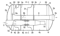
以下、本発明を図に示す実施形態に基づいて具体的に説明する。図1は本発明によるエンジン用マフラの一実施形態を示す横断平面図、図2は図1におけるA−A断面図、図3はセパレータの斜視図である。 Hereinafter, the present invention will be specifically described based on embodiments shown in the drawings. 1 is a cross-sectional plan view showing an embodiment of an engine muffler according to the present invention, FIG. 2 is a cross-sectional view taken along line AA in FIG. 1, and FIG. 3 is a perspective view of a separator.
図示例のエンジン用マフラMは、両端部をエンドプレート2a,2bで閉塞した断面長円形(楕円形)のマフラ本体1内を2つのセパレータ3a,3bによって3つの室4a〜4cに仕切った構成であり、上記マフラ本体1とエンドプレート2a,2bおよびセパレータ3a,3bは、本実施形態においては、それぞれ1重に形成されている。また上記各エンドプレート2a,2bとセパレータ3a,3bの周縁部には、それぞれ短筒状のフランジ部20,30が一体に形成され、そのフランジ部20,30をマフラ本体1内に圧入嵌合させた構成である。
The engine muffler M in the illustrated example has a configuration in which the inside of a muffler body 1 having an oval cross section (elliptical shape) closed at both ends with
図中、5は図に省略したエンジンからの排気を不図示の排気管を介してマフラ本体1内に導く排気導入パイプ、6は排出パイプであり、上記導入パイプ5からマフラ本体1内に導入された排気は、その導入パイプ5の周面に形成した貫通小孔5a,5bから室4a,4b内に流入した後、排出パイプ6の上流側の端部6aおよび排出パイプ6の周面に形成した貫通小孔6bから該排出パイプ6内を経て、その下流側の端部6cからマフラ本体1の外に排出される構成であり、上記室4a,4bは膨張室としての機能を有する。
In the figure, 5 is an exhaust introduction pipe that guides exhaust from the engine (not shown) into the muffler main body 1 through an unillustrated exhaust pipe, and 6 is a discharge pipe, which is introduced into the muffler main body 1 from the introduction pipe 5. The discharged exhaust gas flows into the chambers 4 a and 4 b from the through
上記導入パイプ5の下流側の端部5cは室4c内に開口し、その開口端5cと、上記導入パイプ5の周面に形成した貫通小孔5bとの間の導入パイプ5内の管路が、共鳴型消音器における、いわゆる咽喉部としての機能を有し、上記室4cが共鳴室としての機能を有する。
A downstream end portion 5c of the introduction pipe 5 opens into the
前記各セパレータ3a,3bの周縁部には、前述のようにマフラ本体1との嵌合用の短筒状フランジ部30が一体に設けられ、その各短筒状フランジ部30の一部をマフラ本体1の軸線方向と平行な方向(以下、単に軸線方向という)に延長して舌片状の遮音体31を上記フランジ部30と一体に設けたものである。その遮音体31は長円形マフラ本体1の短軸方向両側の曲率半径が大きい部分の内面を覆うようにして、それらに圧接して設けられている。
As described above, the short
その遮音体31をマフラ本体1の内面に圧接させる手段として、本実施形態においてはマフラ本体1内に長円形のセパレータ3a,3bを押し込むことによって、その長円形セパレータの長軸方向にマフラ本体1が押し広げられると同時に、短軸方向にマフラ本体1が狭められることによって、その内面がセパレータ3a,3bの周縁部に密着するようにしたものである。
As a means for pressing the
なお、上記各セパレータ3a,3bの上記短軸方向に対向する遮音体31・31の間隔を予め装填時の間隔よりもやや広めに形成して、その両遮音体31・31の間隔を押し縮めながらマフラ本体1内に装着し、その各遮音体31・31の弾性復元力でマフラ本体1の内面に圧接させるようにすれば、上記マフラ本体1に対する遮音体31・31の圧接力を更に高めることができる。
In addition, the interval between the
上記遮音体31は、マフラ本体1内の全ての室4a〜4cに設けてもよいが、例えば共鳴型消音器の共鳴室内には必ずしも設けなくてもよい。その理由は、上記のような共鳴室内に排気が流入することは少なく、その共鳴室内からマフラ本体を透過して外部に洩れる透過音も少ないからである。
The
そこで、本実施形態においては、共鳴室としての機能を有する室4c内には遮音体31を設けることなく、排気が多く流通する排気膨張室としての機能を有する室4a,4bにのみ遮音体31を設けたものである。それによって共鳴室に遮音体31を設けた場合よりも重量やコストを軽減できると共に、排気騒音が透過しやすい膨張室に遮音体31を設けることで消音性能を向上させることが可能となる。
Therefore, in the present embodiment, the sound
上記のようにしてセパレータ3a,3bの短筒状フランジ部30の一部を延長してマフラ本体1の内面を覆う遮音体31を設けたから、その遮音体31でマフラ本体1を通過する透過音が低減されると共に、上記遮音体31をマフラ本体1の内面に圧接させたことによって、該マフラ本体1の剛性およびダンピング効果が増し、それによってもマフラ本体1を通過する透過音を低減することができる。その結果、上記両者の作用が相まって透過音が大幅に低減され、消音性能のよいエンジン用マフラを容易・安価に得ることが可能となるものである。
Since the
なお上記遮音体31は、必ずしもマフラ本体1の周方向全長に設ける必要はなく、少なくとも図のように長円形マフラ本体1の短軸側の曲率半径が大きく剛性の低い部分(図2で上部および下部)に設ければよいので重量の増加を抑制することができる。また遮音体31のマフラ本体1の軸線方向と平行な方向の長さ(図1で左右方向の長さ)は適宜であるが、あまり短いと遮音効果が低下するので、好ましくは遮音体31を設けた室3a、3bのマフラ本体1近傍における軸線方向長さの半分程度もしくはそれ以上の長さとするのが望ましい。
The
さらに必要に応じて例えば図4に示すように遮音体31に多数の貫通小孔32や不貫通の凹部等を形成すれば、重量を軽減することができる。この場合、上記貫通小孔32は、あまり大きいと遮音効果が低下するので、直径3mm以下とするのが望ましい。その程度の大きさの貫通小孔であれば、図のように多数設けても遮音効果があまり低下しないことが実験により確かめられている。
Further, if necessary, for example, as shown in FIG. 4, the weight can be reduced by forming a large number of small through
上記実施形態は、セパレータ3a,3bの短筒状フランジ部30の一部を延長して遮音体31を設けたが、図のようなマフラ本体1に嵌合する短筒状フランジ部20を有するエンドプレート2a,2bにあっては、そのエンドプレートのフランジ部20の一部を延長して遮音体を設けることもできる。
In the above embodiment, a part of the short
また上記のような構成のマフラを製造するに当たっては、セパレータ3a,3bと排気導入パイプ5および排出パイプ6とを1つのユニットとして予め組付けた状態でマフラ本体1内に一括して挿入(圧入)することができる。また、場合によってはエンドプレート2a,2bのいずれか一方または両方をも上記ユニットに予め組付けた状態でマフラ本体1内に挿入(圧入)することもできる。そして挿入後は図1のようにマフラ本体1の両端部とエンドプレート2a,2bのフランジ部20とを溶接W等で固着すれば、容易に製造することができる。
In manufacturing the muffler having the above-described configuration, the
以上のように、本発明によるエンジン用マフラは、セパレータ3a,3bまたは/およびエンドプレート2a,2bの周縁部に、マフラ本体1との嵌合用の短筒状フランジ部を一体に設けると共に、その短筒状フランジ部の一部を延長して上記長円形マフラ本体1の少なくとも短軸側の内面を覆う遮音体31を、上記フランジ部と一体に且つマフラ本体内面に圧接させて設けたから、上記遮音体31による直接的な透過音防止効果と、上記遮音体31をマフラ本体内面に圧接させてマフラ本体の剛性およびダンピング効果を高めることによって透過音を減少させる効果とが相まって軽量で消音性能のよいエンジン用マフラを提供することが可能となるもので、この種のマフラの設計の自由度や産業上の利用可能性を増大させることができる。
As described above, the engine muffler according to the present invention is provided with the short cylindrical flange portion for fitting with the muffler body 1 integrally on the periphery of the
M エンジン用マフラ
1 マフラ本体
2a、2b エンドプレート
3a、3b セパレータ
30 短筒状フランジ部
31 遮音体
4a〜4c 室
5 排気導入パイプ
6 排出パイプ
6a、6b 貫通小孔
6c 下流側端部
M Engine muffler 1
Claims (5)
前記セパレータまたは/およびエンドプレートの周縁部に、前記マフラ本体との嵌合用の短筒状フランジ部を一体に設けると共に、
前記短筒状フランジ部の突出する側に前記短筒状フランジ部の一部を延長して前記マフラ本体の少なくとも短軸側の内面を覆う舌片状の遮音体を一体に設け、
前記遮音体と前記短筒状フランジ部とを有する前記セパレータまたは/およびエンドプレートを一つの部材で構成し、
前記遮音体を前記マフラ本体の内面に圧接して設けることを特徴とするエンジン用マフラ。 In the muffler for an engine in which the inside of the muffler body having an oblong cross section whose both ends are closed with end plates is divided into a plurality of chambers by separators,
The peripheral portion of the front SL separator or / and the end plate, provided with integrally short cylindrical flange portion for engagement with said muffler main body,
The provided tongue-like sound insulating material covering the inner surface of at least the minor axis side of the on the side of the protrusion of the short tubular flange by extending a portion of the short cylindrical flange portion and the Ma hula body together,
The separator or / and the end plate having the sound insulating body and the short cylindrical flange portion are constituted by one member,
Muffler for an engine, characterized in that Ru is provided in pressure contact with the sound insulating member on the inner surface of the muffler body.
前記セパレータの周縁部に、前記マフラ本体との嵌合用の短筒状フランジ部を一体に設けると共に、While integrally providing a short cylindrical flange portion for fitting with the muffler body on the peripheral portion of the separator,
前記短筒状フランジ部の突出する側に前記短筒状フランジ部の一部を延長して前記マフラ本体の短軸側の内面を覆う舌片状の遮音体を一体に設け、A tongue-like sound insulator that integrally extends the short shaft side inner surface of the muffler body by extending a part of the short cylindrical flange portion on the projecting side of the short cylindrical flange portion,
前記遮音体と前記短筒状フランジ部とを有する前記セパレータを一つの部材で構成し、The separator having the sound insulator and the short cylindrical flange portion is constituted by one member,
前記遮音体を前記マフラ本体の内面に圧接して設けるエンジン用マフラの製造方法であって、An engine muffler manufacturing method in which the sound insulator is provided in pressure contact with the inner surface of the muffler body,
前記セパレータの前記短軸方向で対向する前記遮音体の間隔を押し縮めながら、前記セパレータを前記マフラ本体内に押し込み、前記対向する前記遮音体を弾性復元力で前記マフラ本体の内面に圧接する工程を備えることを特徴とするエンジン用マフラの製造方法。A step of pressing the separator into the muffler main body while pressing and shrinking a distance between the sound insulating bodies facing each other in the minor axis direction of the separator, and pressing the opposed sound insulating bodies against the inner surface of the muffler main body with an elastic restoring force An engine muffler manufacturing method comprising:
Priority Applications (1)
| Application Number | Priority Date | Filing Date | Title |
|---|---|---|---|
| JP2005002736A JP4576239B2 (en) | 2005-01-07 | 2005-01-07 | Engine muffler |
Applications Claiming Priority (1)
| Application Number | Priority Date | Filing Date | Title |
|---|---|---|---|
| JP2005002736A JP4576239B2 (en) | 2005-01-07 | 2005-01-07 | Engine muffler |
Publications (2)
| Publication Number | Publication Date |
|---|---|
| JP2006189007A JP2006189007A (en) | 2006-07-20 |
| JP4576239B2 true JP4576239B2 (en) | 2010-11-04 |
Family
ID=36796435
Family Applications (1)
| Application Number | Title | Priority Date | Filing Date |
|---|---|---|---|
| JP2005002736A Expired - Fee Related JP4576239B2 (en) | 2005-01-07 | 2005-01-07 | Engine muffler |
Country Status (1)
| Country | Link |
|---|---|
| JP (1) | JP4576239B2 (en) |
Families Citing this family (6)
| Publication number | Priority date | Publication date | Assignee | Title |
|---|---|---|---|---|
| JP2009024650A (en) * | 2007-07-23 | 2009-02-05 | Sankei Giken Kogyo Co Ltd | Muffler and its manufacturing method |
| KR100981980B1 (en) | 2008-06-11 | 2010-09-13 | 세종공업 주식회사 | Muffler moudle |
| JP2015014210A (en) * | 2013-07-03 | 2015-01-22 | 本田技研工業株式会社 | Muffler |
| JP5934150B2 (en) * | 2013-07-03 | 2016-06-15 | 本田技研工業株式会社 | Silencer |
| US9261009B2 (en) | 2013-07-03 | 2016-02-16 | Honda Motor Co., Ltd. | Automotive muffler |
| JP6437935B2 (en) * | 2016-01-14 | 2018-12-12 | 株式会社ユタカ技研 | Exhaust silencer |
Citations (5)
| Publication number | Priority date | Publication date | Assignee | Title |
|---|---|---|---|---|
| JPS52100455U (en) * | 1976-01-29 | 1977-07-29 | ||
| JPS62111919U (en) * | 1985-12-28 | 1987-07-16 | ||
| JPS63154718U (en) * | 1987-03-30 | 1988-10-11 | ||
| JPH0614429U (en) * | 1992-07-30 | 1994-02-25 | 株式会社ユタカ技研 | Partition structure of vehicle muffler |
| JP2002364356A (en) * | 2001-06-07 | 2002-12-18 | Mitsubishi Motors Corp | Exhaust muffler |
-
2005
- 2005-01-07 JP JP2005002736A patent/JP4576239B2/en not_active Expired - Fee Related
Patent Citations (5)
| Publication number | Priority date | Publication date | Assignee | Title |
|---|---|---|---|---|
| JPS52100455U (en) * | 1976-01-29 | 1977-07-29 | ||
| JPS62111919U (en) * | 1985-12-28 | 1987-07-16 | ||
| JPS63154718U (en) * | 1987-03-30 | 1988-10-11 | ||
| JPH0614429U (en) * | 1992-07-30 | 1994-02-25 | 株式会社ユタカ技研 | Partition structure of vehicle muffler |
| JP2002364356A (en) * | 2001-06-07 | 2002-12-18 | Mitsubishi Motors Corp | Exhaust muffler |
Also Published As
| Publication number | Publication date |
|---|---|
| JP2006189007A (en) | 2006-07-20 |
Similar Documents
| Publication | Publication Date | Title |
|---|---|---|
| CA2509746C (en) | Exhaust device for vehicle engine | |
| JP6039880B2 (en) | Silencer | |
| JP4576239B2 (en) | Engine muffler | |
| US20110073209A1 (en) | Flexible vibration absorbing tube | |
| JP5389332B2 (en) | Exhaust system parts | |
| JP2020073801A (en) | Noise eliminator | |
| US20050115764A1 (en) | Muffler | |
| US7464789B2 (en) | Exhaust silencer for internal combustion engine | |
| JP4459218B2 (en) | Vehicle exhaust silencer | |
| US7690479B2 (en) | Silencer | |
| JP2006348896A5 (en) | ||
| JP6137683B2 (en) | Engine exhaust muffler | |
| JP4508951B2 (en) | Fixing structure of exhaust pipe in silencer for vehicle | |
| JP5363542B2 (en) | Support device for exhaust parts | |
| CN110080855B (en) | Silencer with improved structure | |
| JP6169035B2 (en) | Silencer structure for exhaust noise of fuel cell vehicles | |
| JP4144149B2 (en) | Automotive exhaust silencer | |
| JP4291727B2 (en) | Delivery pipe | |
| WO2014208300A1 (en) | Exhaust muffler | |
| JP2005233167A (en) | Submuffler for automobile | |
| JP3264131B2 (en) | Automotive exhaust silencer | |
| JP7419218B2 (en) | Method for manufacturing components of a silencer and method for manufacturing a silencer | |
| JP2007132271A (en) | Silencer and inner piece used for same | |
| JP2006233890A (en) | Muffler for internal combustion engine | |
| JP4582476B2 (en) | Silencer |
Legal Events
| Date | Code | Title | Description |
|---|---|---|---|
| A621 | Written request for application examination |
Free format text: JAPANESE INTERMEDIATE CODE: A621 Effective date: 20071219 |
|
| A131 | Notification of reasons for refusal |
Free format text: JAPANESE INTERMEDIATE CODE: A131 Effective date: 20100217 |
|
| A977 | Report on retrieval |
Free format text: JAPANESE INTERMEDIATE CODE: A971007 Effective date: 20100218 |
|
| A521 | Written amendment |
Free format text: JAPANESE INTERMEDIATE CODE: A523 Effective date: 20100409 |
|
| TRDD | Decision of grant or rejection written | ||
| A01 | Written decision to grant a patent or to grant a registration (utility model) |
Free format text: JAPANESE INTERMEDIATE CODE: A01 Effective date: 20100728 |
|
| A01 | Written decision to grant a patent or to grant a registration (utility model) |
Free format text: JAPANESE INTERMEDIATE CODE: A01 |
|
| A61 | First payment of annual fees (during grant procedure) |
Free format text: JAPANESE INTERMEDIATE CODE: A61 Effective date: 20100823 |
|
| R150 | Certificate of patent or registration of utility model |
Free format text: JAPANESE INTERMEDIATE CODE: R150 |
|
| FPAY | Renewal fee payment (event date is renewal date of database) |
Free format text: PAYMENT UNTIL: 20130827 Year of fee payment: 3 |
|
| R250 | Receipt of annual fees |
Free format text: JAPANESE INTERMEDIATE CODE: R250 |
|
| R250 | Receipt of annual fees |
Free format text: JAPANESE INTERMEDIATE CODE: R250 |
|
| R250 | Receipt of annual fees |
Free format text: JAPANESE INTERMEDIATE CODE: R250 |
|
| R250 | Receipt of annual fees |
Free format text: JAPANESE INTERMEDIATE CODE: R250 |
|
| R250 | Receipt of annual fees |
Free format text: JAPANESE INTERMEDIATE CODE: R250 |
|
| LAPS | Cancellation because of no payment of annual fees |