JP4576206B2 - Method for producing soft magnetic material - Google Patents
Method for producing soft magnetic material Download PDFInfo
- Publication number
- JP4576206B2 JP4576206B2 JP2004319734A JP2004319734A JP4576206B2 JP 4576206 B2 JP4576206 B2 JP 4576206B2 JP 2004319734 A JP2004319734 A JP 2004319734A JP 2004319734 A JP2004319734 A JP 2004319734A JP 4576206 B2 JP4576206 B2 JP 4576206B2
- Authority
- JP
- Japan
- Prior art keywords
- soft magnetic
- powder
- raw material
- coupling agent
- magnetic material
- Prior art date
- Legal status (The legal status is an assumption and is not a legal conclusion. Google has not performed a legal analysis and makes no representation as to the accuracy of the status listed.)
- Expired - Fee Related
Links
Images


Description
本発明は、ソレノイドアクチュエータやトランスのコア材等に適用される軟磁性材料の製造方法に関する。 The present invention relates to a method for manufacturing a soft magnetic material applied to a solenoid actuator, a core material of a transformer, and the like.
近年、軟磁性材料の高透磁率化、低鉄損化等を目的として、軟磁性粉末のプレス成形物を焼結して軟磁性材料を製造する技術が研究されている。この製造技術は、例えば、特許文献1に示すように、まず、アトマイズ合金の粉末の粒子表面を空気中で酸化させて、表面に軟磁性のNi−Znフェライト薄膜を形成し、その後、窒素雰囲気中でAlのスパッタリングを行って、AlNを主成分とする絶縁膜をNi−Znフェライト薄膜上に形成する。その後、この軟磁性粉末にB2O3粉末を添加し、これを所定形状にプレス成形した後、ホットプレス法により、プレス成形物を加圧しながら温度1000℃で焼結して、軟磁性材焼結体を製造するというものである。
In recent years, a technique for producing a soft magnetic material by sintering a press-molded product of soft magnetic powder has been studied for the purpose of increasing the magnetic permeability and lowering iron loss of the soft magnetic material. In this manufacturing technique, for example, as shown in
しかしながら、上記従来の製造方法では、アトマイズ合金粉末の粒子表面に軟磁性のNi−Znフェライト薄膜を形成する工程や、窒素雰囲気中でAlのスパッタリングを行って絶縁膜を形成する工程に手間がかかって、製造コストが高くなるという問題がある。
また、プレス成形時に絶縁膜が亀裂してしまい、得られる軟磁性材料の鉄損が大きくなるという問題がある。また、上記亀裂を防止するために絶縁膜の膜厚を厚く形成すると、軟磁性材料中の磁性材の密度が低下して飽和磁束密度が低下してしまい、磁気特性が悪くなるという問題も起こりうる。
However, in the above conventional manufacturing method, it takes time to form a soft magnetic Ni—Zn ferrite thin film on the surface of the atomized alloy powder particles and to form an insulating film by sputtering Al in a nitrogen atmosphere. Therefore, there is a problem that the manufacturing cost becomes high.
In addition, there is a problem that the insulating film is cracked during press molding, and the resulting soft magnetic material has a large iron loss. In addition, if the insulating film is formed thick in order to prevent the cracks, the density of the magnetic material in the soft magnetic material is lowered, the saturation magnetic flux density is lowered, and the magnetic characteristics are deteriorated. sell.
本発明は、かかる従来の問題点に鑑みてなされたもので、低鉄損で磁気特性に優れた軟磁性材料を容易に製造できる製造方法を提供しようとするものである。 The present invention has been made in view of such conventional problems, and an object of the present invention is to provide a production method capable of easily producing a soft magnetic material having low iron loss and excellent magnetic characteristics.
そこで、我々は、先に特願2003−391318として、粉体表面に、SiO2膜を形成した軟磁性材料を提供した。しかしながら、SiO2の膜を粉体表面に絶縁膜として形成した場合には、粉体の圧粉・焼結工程においてプレス成形時の絶縁膜の亀裂発生や焼結工程における絶縁膜亀裂が発生してしまい、これらの補修が必要となった。(後述の焼結工程は本SiO2絶縁膜を対象としているため。)
そこで、本発明は、高電気抵抗特性を有する隔膜部により区画された多数の領域内にそれぞれ軟磁性金属よりなる母相が存在してなる軟磁性材料を製造する方法であって、
軟磁性金属よりなる母相粒子の表面に上記隔膜部となる酸化膜を被覆してなる軟磁性粒子の集まりである原料粉末を準備し、
上記母相粒子を構成する軟磁性金属よりも酸化反応性が高い金属元素を含むシランカップリング剤を上記原料粉末に添加するカップリング剤添加工程と、
上記シランカップリング剤が添加された上記原料粉末を加圧成形して所望形状の成形体を形成する加圧成形工程と、
該加圧成形工程後に、上記成形体を焼成炉に入れ、所定の焼成温度下において上記焼成炉内に加湿ガスを供給する工程と、上記加湿ガスの供給を停止して上記焼成炉内を真空引きする工程とを交互に2回以上繰り返す焼成工程とを有することを特徴とする軟磁性材料の製造方法にある(請求項1)。
Therefore, we previously provided a soft magnetic material in which a SiO 2 film is formed on the powder surface as Japanese Patent Application No. 2003-391318. However, when an SiO 2 film is formed on the powder surface as an insulating film, cracking of the insulating film during press molding and insulating film cracking during the sintering process occur during the powder compaction and sintering process. These repairs were necessary. (Since the sintering process described later is for the present SiO 2 insulating film.)
Therefore, the present invention is a method for producing a soft magnetic material in which a parent phase made of a soft magnetic metal exists in each of a number of regions partitioned by a diaphragm portion having high electrical resistance characteristics,
Preparing a raw material powder that is a collection of soft magnetic particles obtained by coating the surface of the mother phase particles made of a soft magnetic metal with the oxide film serving as the diaphragm,
A coupling agent addition step of adding a silane coupling agent containing a metal element having a higher oxidation reactivity than the soft magnetic metal constituting the matrix phase particles to the raw material powder ;
A pressure molding step of pressure-molding the raw material powder to which the silane coupling agent is added to form a molded body having a desired shape ;
After the pressure molding step, the molded body is placed in a firing furnace, a humidified gas is supplied into the firing furnace at a predetermined firing temperature, and the supply of the humidified gas is stopped and the interior of the firing furnace is evacuated. A method of producing a soft magnetic material, characterized by comprising a firing step of alternately repeating the drawing step twice or more .
本発明では、上記のごとく、上記母相粒子の表面に上記酸化膜を被覆してなる軟磁性粒子の集まりである原料粉末を用い、これに上記カップリング剤を添加した状態で加圧成形する。
ここで、上記カップリング剤は、上記絶縁膜の表面をさらに被覆するように配されるが、潤滑機能を有するため軟磁性粒子間の潤滑を良好にする機能とともに、上記絶縁膜の耐性を高め、絶縁膜を強化する機能を有するものである。そのため、上記加圧成形時には、カップリング剤なしで行う場合に比べて、軟磁性粒子同士が擦れ合って酸化膜が破れたりする不具合が大幅に減少する。
In the present invention, as described above, the raw material powder, which is a collection of soft magnetic particles obtained by coating the surface of the matrix phase particles with the oxide film, is used, and pressure molding is performed with the coupling agent added thereto. .
Here, the coupling agent is arranged so as to further cover the surface of the insulating film, but since it has a lubricating function, it enhances the resistance of the insulating film as well as the function of improving the lubrication between the soft magnetic particles. It has a function to reinforce the insulating film. Therefore, at the time of the above pressure molding, the problem that the soft magnetic particles rub against each other and the oxide film is broken is greatly reduced as compared with the case where the coupling agent is not used.
さらに、上記カップリング剤には、上記母相粒子を構成する軟磁性金属よりも酸化反応性が高い金属元素が含まれている。そのため、上記酸化膜に損傷があった場合には、その部分に存在する上記カップリング剤の上記金属元素が焼結工程において酸化し、損傷部分を補修する効果を発揮する。 Furthermore, the coupling agent contains a metal element having higher oxidation reactivity than the soft magnetic metal constituting the matrix particles. Therefore, when the oxide film is damaged, the metal element of the coupling agent existing in the portion is oxidized in the sintering process, and the effect of repairing the damaged portion is exhibited.
すなわち、本発明の製造方法においては、上記酸化膜を被覆してなる軟磁性粒子を用い、これに上記特定のカップリング剤を添加した状態で加圧成形及びその後の焼結を行うので、酸化膜損傷抑制効果(潤滑機能)と酸化膜補修効果とが得られ、酸化膜を連ねて構成される上記隔膜部を非常に健全な状態とすることができる。
それ故、上記軟磁性金属よりなる母相粒子が最初の体積をほぼ維持したまま高電気抵抗の隔膜部によって区画され、渦電流の発生による鉄損を低減することができる。
したがって、本発明によれば、低鉄損で磁気特性に優れた軟磁性材料を容易に製造することができる。
That is, in the production method of the present invention, the soft magnetic particles coated with the oxide film are used, and pressure molding and subsequent sintering are performed with the specific coupling agent added thereto. A film damage suppressing effect (lubricating function) and an oxide film repairing effect are obtained, and the above-mentioned diaphragm portion constituted by connecting the oxide films can be brought into a very healthy state.
Therefore, the mother phase particles made of the soft magnetic metal are partitioned by the high electric resistance diaphragm while maintaining the initial volume, and iron loss due to generation of eddy current can be reduced.
Therefore, according to the present invention, a soft magnetic material having low iron loss and excellent magnetic characteristics can be easily manufactured.
本発明の製造方法に適用するカップリング剤としては、上記の潤滑機能と補修機能の両方を発揮しうるシランカップリング剤が有効である。 The coupling agent to be applied to the production method of the present invention, the Hare Ru silane coupling agent exhibit both of the above lubricating function and repair function is enabled.
シランカップリング剤は、通常、Y〜CH2SiX3の一般式をもつ。Xはアルコキシ基やハロゲンなどの加水分解性の置換基で無機質と反応し,Yは有機質と反応しやすいビニル基,エポキシ基,アミノ基などである。
具体的には、例えば、ビニル基を備えたビニルトリクロルシラン、エポキシ基を備えた2−(3,4エポキシシクロヘキシル)エチルトリメトキシシラン、アミノ基を備えたN−フェニル−3−アミノプロピルトリメトキシシラン、イソシアネート基を備えた3−イソシアネートプロピルトリエトキシシラン、アクリロキシ基を備えた3−アクリロキシプロピルトリメトキシシラン等がある。
The silane coupling agent usually has a general formula of Y to CH 2 SiX 3 . X is a hydrolyzable substituent such as an alkoxy group or a halogen, and reacts with an inorganic substance, and Y is a vinyl group, an epoxy group, an amino group or the like that easily reacts with an organic substance.
Specifically, for example, vinyltrichlorosilane having a vinyl group, 2- (3,4 epoxycyclohexyl) ethyltrimethoxysilane having an epoxy group, N-phenyl-3-aminopropyltrimethoxy having an amino group Examples include silane, 3-isocyanatopropyltriethoxysilane having an isocyanate group, and 3-acryloxypropyltrimethoxysilane having an acryloxy group.
また、上記シランカップリング剤(以下、適宜、単にカップリング剤という)の添加量は、上記原料粉末におけるすべての上記軟磁性粒子の表面を覆うことが可能な量とすることが好ましい(請求項2)。これにより、加圧成形時の潤滑機能を高めることができる。
具体的な添加量を決定するに当たっては、例えば、採用したカップリング剤の最小被覆面積(m2/g)と、原料粉末の比表面積(m2/g)とによって算出することが可能である。
ここで、カップリング剤の最小被覆面積は、最小被覆面積モデルによって算出される。具体的には、一つの分子に着目し、加水分解性基であるメトキシ基あるいはエトキシ基の外形を包絡する円の面積を1分子あたりの被覆面積とする。これに気体定数(アボガドロ数)6.02×10²³を乗じて1モルあたりの被覆面積を算出する。これをシランカップリング剤の分子量で除して上記最小被覆面積(m2/g)を算出する。
また、原料粉末の比表面積は、気体吸着法によって算出される。具体的には、分子の断面積がわかっている気体を用いて、被測定物の個体表面を単分子層で覆うのに要する量(単分子吸着量)を測定することで固体の表面積、すなわち比表面積が算出される。
The amount of the silane coupling agent (hereinafter simply referred to as a coupling agent as appropriate) is preferably an amount that can cover the surfaces of all the soft magnetic particles in the raw material powder ( claims). 2 ). Thereby, the lubrication function at the time of pressure molding can be improved.
In determining the specific amount, for example, it can be calculated by the minimum coverage area of coupling agent employed (m 2 / g), and the specific surface area of the raw material powder (m 2 / g) .
Here, the minimum coating area of the coupling agent is calculated by a minimum coating area model. Specifically, paying attention to one molecule, the area of a circle enclosing the outer shape of the hydrolyzable methoxy group or ethoxy group is defined as a covering area per molecule. The coating area per mole is calculated by multiplying this by the gas constant (Avocado number) of 6.02 × 10 23 . This is divided by the molecular weight of the silane coupling agent to calculate the minimum covering area (m 2 / g).
The specific surface area of the raw material powder is calculated by a gas adsorption method. Specifically, by using a gas whose molecular cross-sectional area is known, the surface area of the solid is measured by measuring the amount required to cover the solid surface of the object to be measured with a monomolecular layer (monomolecular adsorption amount), that is, The specific surface area is calculated.
そして、上記カップリング剤の最小被覆面積をA(m2/g)、上記原料粉末の比表面積をB(m2/g)とした場合、これらの関係が、A>Bを満足すればよい。過剰なシランカップリング剤は,粉体焼結時の加熱により気化して排出されるために問題ない。ただし,コスト上は過剰量を最小限に留めることが好ましい。これにより、軟磁性粒子の表面を十分にカップリング剤により濡らすことができ、かつ、余剰のカップリング剤を抑制することができる。 Then, when the minimum coating area of the coupling agent is A (m 2 / g) and the specific surface area of the raw material powder is B (m 2 / g), these relationships may satisfy A> B. . Excess silane coupling agent is not a problem because it is vaporized and discharged by heating during powder sintering. However, in terms of cost, it is preferable to keep the excess amount to a minimum. Thereby, the surface of the soft magnetic particles can be sufficiently wetted by the coupling agent, and excess coupling agent can be suppressed.
また、上記カップリング剤の添加方法としては、例えば次のような湿式法、乾式法、及びスプレー法などの方法がある。
湿式法は、例えば、上記原料粉末を水に分散させ、スラリー状態になったところにシランカップリング剤を直接または、有機溶剤(もしくは水)で希釈した溶液を添加していく方法である。その後、攪拌後静置して原料粉末を沈降分離し、乾燥させる。
Examples of the method for adding the coupling agent include the following wet methods, dry methods, and spray methods.
The wet method is, for example, a method in which the raw material powder is dispersed in water and a solution obtained by diluting the silane coupling agent directly or with an organic solvent (or water) is added to a slurry state. Thereafter, the mixture is allowed to stand after stirring to precipitate and separate the raw material powder, followed by drying.
乾式法は、攪拌機によって原料粉末を強制攪拌しながら、シランカップリング剤を直接または、有機溶剤(もしくは水)で希釈した溶液を乾燥空気や窒素ガスで噴射させて処理していく方法である。
スプレー法は、高温の原料粉末にシランカップリング剤を直接または、有機溶剤(もしくは水)で希釈した溶液をスプレーする方法である。この方法は、乾燥の必要がなく、工程が簡略化できるが、換気や引火に対する注意が必要である。
The dry method is a method in which a raw material powder is forcibly stirred with a stirrer, and a solution obtained by diluting a silane coupling agent directly or with an organic solvent (or water) is sprayed with dry air or nitrogen gas.
The spray method is a method of spraying a solution obtained by diluting a silane coupling agent directly or with an organic solvent (or water) onto a high-temperature raw material powder. This method does not require drying and can simplify the process, but requires attention to ventilation and ignition.
また、上記原料粉末は、鉄を主成分として鉄よりも酸化反応性の高い第2の元素を含有する出発粒子の集まりである出発粉末を酸化性雰囲気中で加熱し、上記出発粒子の表層部に存在する上記第2の元素を酸化反応させて上記酸化膜を形成することにより作製することが好ましい(請求項3)。これにより、上記原料粉末を容易に製造することができる。 Further, the raw material powder is obtained by heating a starting powder, which is a collection of starting particles containing a second element having iron as a main component and a higher oxidation reactivity than iron in an oxidizing atmosphere. It is preferable that the oxide film is formed by oxidizing the second element present in the substrate ( claim 3 ). Thereby, the said raw material powder can be manufactured easily.
特に、上記酸化性雰囲気は、不活性ガスに弱酸化性ガスを混入した弱酸化性雰囲気中とすることがより好ましい。
上記原料粉末を作製する際に、弱酸化性雰囲気中において酸化反応を行なうと、出発粉末の表層部における鉄の酸化を抑制し、より酸化反応しやすい第2の元素のみを選択的に酸化させることができる。また、酸化速度が適度に抑制されることで、表面に緻密で高電気抵抗の薄い酸化膜を形成することができ、渦電流に起因する損失(鉄損)の低減に高い効果がある。さらに、酸化膜の薄膜化によって磁性材密度が高くなるので磁気特性が向上し、粉末材料の小粒径化によって高強度化が可能となる。その上、製造工程が簡素となるので、生産性が向上する。
In particular, the oxidizing atmosphere is more preferably a weak oxidizing atmosphere in which a weak oxidizing gas is mixed with an inert gas.
When the raw material powder is produced, if an oxidation reaction is performed in a weakly oxidizing atmosphere, the oxidation of iron in the surface layer portion of the starting powder is suppressed, and only the second element that is more susceptible to the oxidation reaction is selectively oxidized. be able to. In addition, since the oxidation rate is moderately suppressed, a dense oxide film having a high electrical resistance can be formed on the surface, which is highly effective in reducing loss (iron loss) due to eddy current. Furthermore, since the magnetic material density is increased by reducing the thickness of the oxide film, the magnetic characteristics are improved, and the strength can be increased by reducing the particle size of the powder material. In addition, since the manufacturing process is simplified, productivity is improved.
また、上記原料粉末は、鉄を主成分として鉄よりも酸化反応性の高い第2の元素を含有する出発粒子の集まりである出発粉末を酸化性雰囲気中において加熱する酸化処理工程と、還元性雰囲気中において加熱する還元処理工程とを交互に行い、上記出発粒子の表層部に存在する上記第2の元素を酸化反応させて、上記酸化膜を形成することも好ましい。この場合にも、上記原料粉末を容易に製造することができる。 The raw material powder includes an oxidation treatment step of heating a starting powder, which is a collection of starting particles containing iron as a main component and a second element having a higher oxidation reactivity than iron, in an oxidizing atmosphere; It is also preferable that the oxide film is formed by alternately performing a reduction treatment step of heating in an atmosphere and oxidizing the second element present in the surface layer portion of the starting particles . Also in this case, the raw material powder can be easily produced.
また、この場合にも、特に、上記酸化性雰囲気は、不活性ガスに弱酸化性ガスを混入した弱酸化性雰囲気中とすることがより好ましい。
また、上記酸化処理工程を行なった後、さらに、還元性雰囲気中において還元反応させ、その後再び酸化反応させる還元処理工程を行い、上記酸化処理工程と還元処理工程とを繰り返す。このようにすると、内部への酸化の進行を抑制しつつ、表層における第2の元素の酸化を促進して、より高純度で、電気抵抗の高い酸化膜を形成することができる。その結果、磁性材の低鉄損化、磁気特性、生産性の向上が可能となる。
Also in this case, the oxidizing atmosphere is more preferably a weak oxidizing atmosphere in which a weak oxidizing gas is mixed with an inert gas.
Further, after the oxidation treatment step is performed, a reduction treatment step is further performed in which a reduction reaction is performed in a reducing atmosphere and then an oxidation reaction is performed again, and the oxidation treatment step and the reduction treatment step are repeated. By doing so, it is possible to promote the oxidation of the second element in the surface layer while suppressing the progress of oxidation to the inside, and to form an oxide film with higher purity and higher electrical resistance. As a result, it is possible to reduce the iron loss, magnetic characteristics, and productivity of the magnetic material.
また、上記第2の元素がSi、Ti、Al、Crから選択される少なくとも一種であることが好ましい(請求項4)。
これらの元素は、酸化反応させる際のギプスの自由エネルギーΔGが、鉄より小さく、酸化反応が進みやすいので、酸化膜の原料として好適である。
Further, it is preferably at least one said second element is selected Si, Ti, Al, from Cr (claim 4).
These elements are suitable as a raw material for an oxide film because the free energy ΔG of the cast during the oxidation reaction is smaller than that of iron and the oxidation reaction easily proceeds.
また、上記弱酸化性雰囲気を得るための上記弱酸化性ガスが水蒸気または一酸化二窒素ガスであることが好ましい。
水蒸気による酸化では、酸化反応がH2Oの還元反応とともに進むので、大気中に比べて反応速度が遅くなる。特に鉄の酸化反応はほぼ平衡状態となり、ほとんど進行しなくなるため、より酸化しやすい第2の元素のみを選択酸化させることが可能になる。一酸化二窒素ガスの場合も、同様の反応形態をとる。
Moreover, it is preferable that the weak oxidizing gas for obtaining the weak oxidizing atmosphere is water vapor or dinitrogen monoxide gas.
In the oxidation with water vapor, the oxidation reaction proceeds together with the reduction reaction of H 2 O, so the reaction rate is slower than in the atmosphere. In particular, since the oxidation reaction of iron is almost in an equilibrium state and hardly proceeds, only the second element that is more easily oxidized can be selectively oxidized. In the case of dinitrogen monoxide gas, the same reaction form is taken.
また、上記弱酸化性ガスを水蒸気とし、常温での相対湿度が50%より高くなるように上記不活性ガスに混入することが好ましい。水蒸気を用いると容易に弱酸化性雰囲気を形成することができ、特に、50%を超える高湿度雰囲気中で酸化させると、上記効果が得やすい。 Moreover, it is preferable that the weak oxidizing gas is water vapor and mixed in the inert gas so that the relative humidity at room temperature is higher than 50%. When water vapor is used, a weakly oxidizing atmosphere can be easily formed. In particular, when oxidation is performed in a high-humidity atmosphere exceeding 50%, the above-described effect can be easily obtained.
また、上記弱酸化性ガスを水蒸気とし、常温での相対湿度が70%〜100%となるように上記不活性ガスに混入することがより好ましい。すなわち、より高湿度の水蒸気雰囲気下で酸化させると、生成する酸化膜の酸化物数密度を高くし、緻密で高電気抵抗の薄膜を形成することができる。 More preferably, the weakly oxidizing gas is water vapor and is mixed into the inert gas so that the relative humidity at room temperature is 70% to 100%. That is, when oxidation is performed in a higher humidity steam atmosphere, the oxide number density of the generated oxide film can be increased, and a dense and high electric resistance thin film can be formed.
また、上記酸化反応は、400〜900℃の温度条件下で行なうことが好ましい。
雰囲気温度が上記範囲より低いと、弱酸化ガスによる鉄の酸化反応系の自由エネルギー変化ΔG<0となって、反応抑制効果が低下する。また、上記範囲より高いと、第2の元素の酸化は進行しやすくなるが、得られる磁性材の特性が低下するおそれがある。上記範囲とすることで、酸化物数密度が高く、緻密で高電気抵抗の酸化膜を形成することができる。
Moreover, it is preferable to perform the said oxidation reaction on 400-900 degreeC temperature conditions.
When the atmospheric temperature is lower than the above range, the free energy change ΔG <0 in the iron oxidation reaction system by the weak oxidizing gas, and the reaction suppressing effect is lowered. Moreover, when higher than the said range, although the oxidation of a 2nd element will advance easily, there exists a possibility that the characteristic of the magnetic material obtained may fall. By setting the content in the above range, an oxide film having a high oxide number density, a dense and high electric resistance can be formed.
また、上記出発粉末は、平均粒径が0.01〜500μmのアトマイズ合金粉末であることが好ましい(請求項5)。
上述した表面酸化膜の薄膜化により、軟磁性粉末の小粒径化が可能となる。そのため、圧縮性のよいアトマイズ粒子を用い、0.01〜500μmの微小粒径とすることができ、軟磁性部材を高強度化、および成形時の形成自由度増大化を図ることができる。
Further, the starting powder preferably has an average particle size of atomized alloy powder 0.01~500Myuemu (claim 5).
By reducing the thickness of the surface oxide film described above, it is possible to reduce the particle size of the soft magnetic powder. Therefore, atomized particles with good compressibility can be used to make the particle size as small as 0.01 to 500 μm, and the strength of the soft magnetic member can be increased and the degree of freedom in forming can be increased.
(実施例1)
本発明の実施例に係る軟磁性材料の製造方法につき、図1〜図5を用いて説明する。
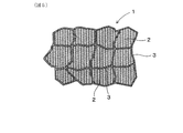
本例において製造する軟磁性材料1は、図5に示すごとく、高電気抵抗特性を有する隔膜部3により区画された多数の領域内にそれぞれ軟磁性金属よりなる母相2が存在してなる軟磁性材料である。
Example 1
A method for manufacturing a soft magnetic material according to an embodiment of the present invention will be described with reference to FIGS.
As shown in FIG. 5, the soft
この軟磁性材料1を製造するに当たって、本例では、図2に示すごとく、出発粒子19(図1)から作製した軟磁性粒子10の集まりである原料粉末100を準備する。軟磁性粒子10は、軟磁性金属よりなる母相粒子20の表面に上記隔膜部3となる酸化膜30を被覆してなるものである。
In producing the soft
次に、図3に示すごとく、上記母相粒子20を構成する軟磁性金属よりも酸化反応性が高い金属元素を含むと共に上記軟磁性粒子10間の潤滑機能を発揮しうるカップリング剤8を、上記原料粉末100に添加するカップリング剤添加工程を行う。
次に、上記カップリング剤8が添加された上記原料粉末100を加圧成形して所望形状の成形体19を形成する加圧成形工程を行う。
その後、該成形体19を焼結する焼結工程を行う。
以下、これらを詳説する。
Next, as shown in FIG. 3, a
Next, a pressure molding process is performed in which the
Then, the sintering process which sinters this molded
These are described in detail below.
<原料粉末>
図2に示すごとく、本例で準備した原料粉末100は、鉄(Fe)を主成分としてSiを第2の元素として含有する母相粒子20と、その表面を被覆するSiO2よりなる酸化膜30を有する軟磁性粒子10よりなるものである。なお、この原料粉末100の製造方法、構成のバリエーション等については後述する。
<Raw material powder>
As shown in FIG. 2, the
<カップリング剤添加工程>
本例では、上記カップリング剤8として、シランカップリング剤の一種である、信越化学株式会社製の製品名:KBM303、化学名:2−(3、4エポキシシクロヘキシル)エチルトリメトキシシランを採用した。また、その添加方法としては、湿式法を採用した。
具体的には、原料粉末100を水に分散させ、スラリー状態になったところにカップリング剤8を直接添加した。その後、攪拌後静置して原料粉末を沈降分離し、乾燥させることにより、図3に示すごとく、すべての軟磁性粒子10の表面全体をカップリング剤8により覆った。
なお、添加方法は、前述した乾式法やスプレー法に変えることも可能である。
<Coupling agent addition process>
In this example, a product name: KBM303 manufactured by Shin-Etsu Chemical Co., Ltd., chemical name: 2- (3,4 epoxycyclohexyl) ethyltrimethoxysilane, which is a kind of silane coupling agent, was used as the
Specifically, the
The addition method can be changed to the dry method or spray method described above.
<加圧成形工程>
加圧成形装置として500kNアムスラ−試験機を用い、成形を行った。金型は超硬製のダイス、及び上下パンチを用いた。原料粉に潤滑剤が添加されていない場合は、ダイスの壁面にZn−St、MoS2等の潤滑剤を塗布し、原料粉を金型のキャビティーに充填する。なお、あらかじめ原料粉末に内部潤滑剤を添加している場合は、金型壁面に潤滑剤を塗布する必要はない。原料を充填した後、上下方向より圧力500〜1500MPaの条件で加圧成形したのち、ダイスから成形体を抜き出し、試料を作製した。
これにより、図4に示すごとく、成形体110を得た。同図から知られるように、各軟磁性粒子10は隣り合うもの同士の間の隙間を縮めるように変形している。酸化膜30は若干破れて損傷部39が形成されたが、後述する比較例1の場合よりも少なかった。また、軟磁性粒子10同士の間の隙間には、上記カップリング剤8が残っていた。
<Pressure forming process>
Molding was performed using a 500 kN Amsler testing machine as a pressure molding apparatus. The die used was a cemented carbide die and upper and lower punches. When the lubricant is not added to the raw material powder, a lubricant such as Zn-St, MoS 2 or the like is applied to the wall surface of the die, and the raw material powder is filled in the mold cavity. When an internal lubricant is added to the raw material powder in advance, it is not necessary to apply the lubricant to the mold wall surface. After filling with the raw material, pressure molding was performed in the vertical direction under the condition of a pressure of 500 to 1500 MPa, and then the molded body was extracted from the die to prepare a sample.
Thereby, as shown in FIG. 4, the molded
<焼成工程>
本例では、真空・ガス置換機構、温度制御機構、酸化・還元反応繰り返し機構、粉体処理機構、加圧機構を有する焼結炉(図示略)を用いた。そして、間欠水蒸気供給による成形体内部表面のSiO2膜形成条件により焼成した。
具体的な条件としては次のような条件を用いた。
・焼成温度:400〜600℃。400℃より低い温度では、SiO2膜形成速度が低く処理に時間がかかる。600℃を超える場合には、粒子と粒子の融合が発生し、SiO2膜の修理が困難となる。
・間欠水蒸気供給条件:上記の焼成温度において、露点80℃以下に加湿したガス(N2ガス、Arガス、あるいはN2+H2混合ガス)を炉内に供給して、粒子表面(Fe−Si)を選択酸化してSiO2膜を形成する工程と、上記加湿ガスの供給を停止し、真空引き(104〜10-2Pa)により反応ガスを交換する工程を2回以上繰り返す。
このような条件によって焼成を行った。これにより、図5に示すごとく、隔膜部3により区画された多数の領域内にそれぞれ軟磁性金属よりなる母相2が存在してなる軟磁性材料1が得られた。
同図より知られるごとく、上記の加圧成形工程において生じた酸化膜30の損傷は、補修されて無くなっており、十分につながった隔膜部3が形成されていた。
<Baking process>
In this example, a sintering furnace (not shown) having a vacuum / gas replacement mechanism, a temperature control mechanism, an oxidation / reduction reaction repeating mechanism, a powder processing mechanism, and a pressurizing mechanism was used. Then, it was fired by SiO 2 film formation conditions of the molded body portion surface by intermittent steam supply.
As specific conditions, the following conditions were used.
-Firing temperature: 400-600 degreeC. At a temperature lower than 400 ° C., the SiO 2 film formation rate is low and the processing takes time. When the temperature exceeds 600 ° C., the particles are fused and repair of the SiO 2 film becomes difficult.
Intermittent water vapor supply conditions: At the above firing temperature, a gas (N 2 gas, Ar gas, or N 2 + H 2 mixed gas) humidified to a dew point of 80 ° C. or lower is supplied into the furnace, and the particle surface (Fe—Si ) a step to selectively oxidized to form a SiO 2 film, to stop the supply of the humidified gas, vacuum (repeated 10 4 to 10 -2 Pa) by a step of replacing the reaction gas more than once.
Firing was performed under such conditions. As a result, as shown in FIG. 5, a soft
As can be seen from the figure, the damage to the
(比較例1)
上記実施例1の作用効果を明らかにすべく、上記カップリング剤添加工程のみを省略してその他は実施例1と同様にした。
その結果、加圧成形工程直後においては、図6に示すごとく、酸化膜30が破れた損傷部39が、実施例1の場合よりも数多く観察された。
また、焼成工程後においては、図7に示すごとく、酸化膜30の損傷部分が隔膜部3の穴あき部38となって、ここで母相粒子同士が連なり、隔膜部3による十分な区画化が達成されていなかった。
(Comparative Example 1)
In order to clarify the effects of the first embodiment, only the coupling agent adding step was omitted, and the others were the same as the first embodiment.
As a result, immediately after the pressure molding step, as shown in FIG. 6, more
In addition, after the firing step, as shown in FIG. 7, the damaged portion of the
上記実施例1と比較例1の比較から、カップリング剤8の添加によって、加圧成形時における酸化膜損傷抑制効果(潤滑機能)と、焼成時ににおける酸化膜補修効果とが有効に発揮され
ることが分かった。
また、実施例1の軟磁性材料1は、上記の健全な隔膜部3の存在によって、渦電流の発生による鉄損を大きく低減することができる。それ故、実施例1の方法によれば、低鉄損で磁気特性に優れた軟磁性材料1を容易に製造することができる。
From the comparison between Example 1 and Comparative Example 1, the addition of the
Moreover, the soft
(原料粉末の製造方法1)
実施例1に適用可能な原料粉末100の製造方法の一例を以下に示す。
軟磁性粒子10の原料となる出発粒子19は、鉄(Fe)を主成分とし、鉄よりも酸化反応性の高い第2の元素を含有する粒子とする。第2の元素としては、例えば、Si、Ti、Al、Cr等が挙げられ、これら元素から選択される少なくとも一種ないし二種以上を含有する合金、具体的には、Fe−Si合金、Fe−Ti合金、Fe−Al合金、Fe−Cr合金、Fe−Al−Si合金等の粒子が使用される。これらのうち、Fe−Si合金は、例えばFe:95〜99.9%、Si:0.1〜5%の組成比のものを、Fe−Al合金は、例えば、Fe:92.5〜97.5%、Al:2.5〜7.5%の組成比のものを、Fe−Al−Si合金は、例えばFe:90〜97%、Al:3.5〜6.5%、Si:0.1〜5%の組成比のものを用いることができる。
(
An example of the manufacturing method of the
The starting
ここで、一般に、SiやAl等の組成比は、次の3つの要因(1)〜(3)、
(1)磁気特性を向上させるには、SiやAl等が少ない方がよい。
(2)金属間化合物を形成しない固溶限界内とする。
(3)酸化膜の膜厚は、目標電気抵抗値を確保できる膜厚以上とする。
を考慮して決定される。例えば、(1)の磁気特性の向上のためには、これら元素の組成比を2%以下、好ましくは1%以下とするのがよく、この範囲で十分な酸化膜を形成できる最小限の組成比を選択するとよい。なお、上記出発粒子を二種以上混合して使用してもよい。
Here, in general, the composition ratio of Si, Al, and the like is determined by the following three factors (1) to (3),
(1) In order to improve the magnetic characteristics, it is better that there is less Si, Al or the like.
(2) Within the solid solution limit where no intermetallic compound is formed.
(3) The film thickness of the oxide film is not less than the film thickness that can secure the target electric resistance value.
Is determined in consideration of For example, in order to improve the magnetic characteristics of (1), the composition ratio of these elements should be 2% or less, preferably 1% or less, and the minimum composition capable of forming a sufficient oxide film within this range. Select a ratio. In addition, you may use the said starting particle in mixture of 2 or more types.
上記出発粉末は、水、不活性ガス等の噴霧媒体を用いて合金溶湯を粉化するアトマイズ法で調製されたアトマイズ合金粉末を用いるのがよい。
アトマイズ合金粉末は高純度で圧縮性がよいので、高密度で良好な磁気特性を有する軟磁性材を実現できる。出発粒子の平均粒径は、通常、500μm以下、好ましくは0.01〜10μmとし、所望の平均粒径となるように、粉砕装置(アトライター)を用いて粉砕する。この粉砕工程で、出発粒子の表面に高活性の破面が形成される。なお、出発粒子の平均粒径のより好ましい範囲は、0.01〜5μmである。出発粉末の製造原料は、粉砕しやすいように、焼鈍(アニール)前のものを用い、粉砕中は、粉砕熱による出発粉末の昇温を抑制するために、粉砕用のステンレス容器を水冷するとよい。
As the starting powder, an atomized alloy powder prepared by an atomizing method in which a molten alloy is pulverized using a spray medium such as water or an inert gas is preferably used.
Since the atomized alloy powder has high purity and good compressibility, a soft magnetic material having high density and good magnetic properties can be realized. The average particle diameter of the starting particles is usually 500 μm or less, preferably 0.01 to 10 μm, and is pulverized using a pulverizer (attritor) so as to have a desired average particle diameter. In this pulverization step, a highly active fracture surface is formed on the surface of the starting particles. A more preferable range of the average particle diameter of the starting particles is 0.01 to 5 μm. The raw material for the starting powder is the one before annealing (annealing) so that it can be easily pulverized. During the pulverization, the pulverizing stainless steel container is water-cooled to suppress the temperature rise of the starting powder due to the heat of pulverization. .
なお、上記したアトマイズ法で調製されたアトマイズ合金粉末を用いる場合と、上記した粉砕装置(アトライター)を用いて粉砕された粉末を用いる場合とのいずれかを単独に用いて、原料となる出発粉末を得るようにしてもよい。 In addition, when using the atomized alloy powder prepared by the above-described atomizing method and using the powder pulverized by using the above-described pulverizing apparatus (attritor), the starting material is used as a starting material. You may make it obtain powder.
次いで、出発粉末の表面に、酸化膜を形成する。この表面酸化工程は、不活性ガスに弱酸化性ガスを混入した弱酸化性雰囲気中において、出発粉末を、高温に加熱して、表層部の第2の元素を主に酸化反応させる。
不活性ガスとしては、窒素(N2)ガス等が好適に用いられ、弱酸化性ガスとしては、例えば、水蒸気(H2O)が好適に用いられる。Fe−Si合金粉末を水蒸気(H2O)により酸化させた場合には、粉末表面において、より酸化しやすいSiが選択的に酸化されてSiO2膜を形成するとともに、H2Oが還元されてH2となる。このような条件下では、Feの酸化は抑制され、酸化速度も適度に制御されるので、粉末の表面を覆う高電気抵抗のSiO2膜を、例えば、3〜5μmの膜厚で均一に形成できる。
Next, an oxide film is formed on the surface of the starting powder. In the surface oxidation step, the starting powder is heated to a high temperature in a weakly oxidizing atmosphere in which a weakly oxidizing gas is mixed with an inert gas, and the second element in the surface layer portion is mainly oxidized.
Nitrogen (N 2 ) gas or the like is preferably used as the inert gas, and water vapor (H 2 O) is preferably used as the weak oxidizing gas, for example. When the Fe—Si alloy powder is oxidized with water vapor (H 2 O), Si, which is more easily oxidized, is selectively oxidized on the powder surface to form a SiO 2 film and H 2 O is reduced. Becomes H 2 . Under such conditions, the oxidation of Fe is suppressed and the oxidation rate is appropriately controlled, so that a high electrical resistance SiO 2 film covering the surface of the powder is uniformly formed with a film thickness of 3 to 5 μm, for example. it can.
このように、弱酸化性ガスとしては、酸素化合物のガスであり酸化反応と同時に還元反応が進むガスが好適である。同様の反応形態をとるガスとして、例えば、一酸化二窒素(N2O)ガスを用いても、同様の効果が得られる。 Thus, as the weak oxidizing gas, a gas that is an oxygen compound gas and that undergoes a reduction reaction simultaneously with the oxidation reaction is suitable. The same effect can be obtained by using, for example, dinitrogen monoxide (N 2 O) gas as a gas having the same reaction form.
弱酸化性ガスが水蒸気(H2O)である場合には、雰囲気中に水蒸気を混入させる際に、常温での相対湿度が50%より高くなるようにするとよい。湿度が高いほど粉末表層部でのSiやAl等の第2の元素の酸化反応が促進され、酸化膜中の酸化物数密度が高くなって、緻密で高電気抵抗の絶縁酸化膜が得られる。好適には、常温で70〜100%(相対湿度)の高湿度となるように混入させるとよい。 When the weak oxidizing gas is water vapor (H 2 O), the relative humidity at room temperature is preferably higher than 50% when water vapor is mixed into the atmosphere. The higher the humidity, the more the oxidation reaction of the second element such as Si and Al in the powder surface layer portion is promoted, and the oxide number density in the oxide film is increased, thereby obtaining a dense and high electric resistance insulating oxide film. . Preferably, it is good to mix so that it may become 70-100% (relative humidity) high humidity at normal temperature.
表面酸化工程における加熱手段としては、電気炉等の一般的な加熱炉が用いられる。例えば、電気炉で酸化膜を形成する場合は、雰囲気温度(加熱温度)、加熱時間、出発粉末のSi含有量やAl含有量によって酸化膜の膜厚を調整すればよい。雰囲気温度は、通常、400〜900℃の範囲内で、適宜設定するとよい。雰囲気温度を400℃以上とすることで、鉄の酸化反応のギプスの自由エネルギー変化ΔGを0近傍とすることができ、鉄の酸化を抑制する効果が得られる。雰囲気温度を高くすると酸化膜の形成は進行しやすくなるが、得られる磁性材の特性が低下するおそれがあるため、900℃以下とするのがよい。好ましくは、雰囲気温度を、400〜700℃の範囲とするとよい。 As a heating means in the surface oxidation step, a general heating furnace such as an electric furnace is used. For example, when forming an oxide film with an electric furnace, the film thickness of the oxide film may be adjusted according to the atmospheric temperature (heating temperature), the heating time, the Si content and the Al content of the starting powder. The ambient temperature is usually suitably set within a range of 400 to 900 ° C. By setting the atmospheric temperature to 400 ° C. or higher, the cast free energy change ΔG of the oxidation reaction of iron can be made close to 0, and the effect of suppressing the oxidation of iron can be obtained. If the atmospheric temperature is raised, the formation of the oxide film is likely to proceed, but the characteristics of the obtained magnetic material may be lowered. Preferably, the ambient temperature is in the range of 400 to 700 ° C.
ここで、Fe−Si合金粉末の弱酸化性雰囲気における酸化膜形成のメカニズムについて説明する。FeとSiの各雰囲気における酸化反応式は、以下のようになる。
酸素(O2)による酸化の場合
2Fe+O2→2FeO ・・・(式1)
Si+O2 →SiO2 ・・・(式2)
水蒸気(H2O)による酸化の場合
Fe+H2O →FeO+H2 ・・・(式3)
Si+2H2O→SiO2+H2・・・(式4)
Here, the mechanism of the oxide film formation in the weakly oxidizing atmosphere of the Fe—Si alloy powder will be described. The oxidation reaction formula in each atmosphere of Fe and Si is as follows.
In the case of oxidation with oxygen (O 2 ) 2Fe + O 2 → 2FeO (Formula 1)
Si + O 2 → SiO 2 (Formula 2)
In the case of oxidation with water vapor (H 2 O) Fe + H 2 O → FeO + H 2 (Formula 3)
Si + 2H 2 O → SiO 2 + H 2 (Formula 4)
各反応系におけるギプスの自由エネルギー変化ΔGが大きくなるほど酸化しにくくなる。Siに比べてFeの酸化が起こりにくく、また、酸素(O2)による酸化反応(式1、2)よりも、水蒸気(H2O)による酸化反応(式3、4)が起こりにくい。酸素(O2)による酸化では、FeとSiのいずれの場合も、反応前より反応後の自由エネルギーが低くなり、より安定した状態となる。つまり、ギプスの自由エネルギーΔGは、いずれもマイナスとなり、ΔGの絶対値が大きいSiの方がより酸化しやすいものの、式1、2の反応はいずれも進行する。
As the free energy change ΔG of the cast in each reaction system increases, the oxidation becomes difficult. Oxidation of Fe is less likely to occur than Si, and oxidation reaction (
これに対し、水蒸気(H2O)による酸化では、FeとSiのいずれの場合も、ギプスの自由エネルギーΔGの絶対値が、酸素(O2)による酸化よりも小さくなる。特に、Feは反応前後でギプスの自由エネルギーΔGがほぼ0となるので、式3の反応はほとんど進行せず、式4の反応のみが進むことになる。
In contrast, in the oxidation with water vapor (H 2 O), the absolute value of the free energy ΔG of the cast is smaller than the oxidation with oxygen (O 2 ) in both cases of Fe and Si. In particular, since the free energy ΔG of the cast is almost 0 before and after the reaction, the reaction of
このように、水蒸気(H2O)で酸化させる場合には、Feの酸化を抑制しながら、SiO2酸化膜を選択的に形成することができる。水蒸気(H2O)によるFeの酸化では、全温度範囲でギプスの自由エネルギ−ΔGが0近傍にあり、特に、500℃程度ないしそれ以上の温度範囲では、ギプスの自由エネルギ−ΔGがほぼ0となって、Feの酸化を抑制する効果が高くなる。また、水蒸気(H2O)によるSiの酸化では、H2Oの還元反応が同時に進行するために、酸素(O2)雰囲気下よりも反応が進みにくく、適度な速度で酸化が進行する。このため、内部まで酸化が進行せず磁性材密度を高く保つとともに、粉末表層部に均一なSiO2酸化膜を高密度で形成し、緻密で電気抵抗の高い数nm程度の薄膜とすることができる。 Thus, in case of oxidation with water vapor (H 2 O), while suppressing the oxidation of Fe, it is possible to selectively form the SiO 2 oxide film. In the oxidation of Fe by water vapor (H 2 O), the free energy of the cast −ΔG is in the vicinity of 0 in the entire temperature range, and in particular, the free energy of the cast ΔΔ is almost 0 in the temperature range of about 500 ° C. or higher. Thus, the effect of suppressing the oxidation of Fe is enhanced. In addition, in the oxidation of Si with water vapor (H 2 O), the reduction reaction of H 2 O proceeds simultaneously, so that the reaction is less likely to proceed than in an oxygen (O 2 ) atmosphere, and the oxidation proceeds at an appropriate rate. For this reason, the oxidation does not proceed to the inside, the magnetic material density is kept high, and a uniform SiO 2 oxide film is formed at a high density on the powder surface layer portion to form a dense thin film having a high electrical resistance of about several nanometers. it can.
(原料粉末の製造方法2)
さらに原料粉末の製造方法の具体的な一例を示す。ここでは、Fe−1%Siアトマイズ合金粒子(平均粒径3μmに調製)を出発粒子とし、不活性高湿度雰囲気(例えば、窒素雰囲気下、相対湿度100%)にて、500〜600℃の温度に加熱した。粉末表面に水蒸気(H2O)が供給されると、上述したように、粉体の表面においてFeよりも酸化しやすいSiがH2Oと反応する。すると、表面のSi濃度が低下するので、内部からSiが表面に拡散し、H2Oと反応して選択的に酸化される。一方、相対的に濃度が高くなるFeは内部へ押し戻されるように移動し、Feの酸化は抑制される。これにより、Fe−1%Si合金粉末の表面が、SiO2酸化膜で均一に覆われる。
(
Furthermore, a specific example of the manufacturing method of raw material powder is shown. Here, Fe-1% Si atomized alloy particles (prepared to an average particle size of 3 μm) are used as starting particles, and the temperature is 500 to 600 ° C. in an inert high-humidity atmosphere (for example, a nitrogen atmosphere and a relative humidity of 100%). Heated. When water vapor (H 2 O) is supplied to the powder surface, Si, which is easier to oxidize than Fe, reacts with H 2 O on the powder surface as described above. Then, since the Si concentration on the surface is lowered, Si diffuses from the inside to the surface and reacts with H 2 O to be selectively oxidized. On the other hand, Fe having a relatively high concentration moves so as to be pushed back into the interior, and oxidation of Fe is suppressed. As a result, the surface of the Fe-1% Si alloy powder is uniformly covered with the SiO 2 oxide film.
この時使用する酸化膜の生成装置では、電気炉内に位置する炉芯管の中央に、出発粉末を配置した。そして、窒素(N2)ガスに加湿器で水蒸気(H2O)を混入して相対湿度100%(常温)となるようにした雰囲気ガスを、炉芯管内に所定流量で導入した。温度制御熱電対にて電気炉内を500〜600℃の温度に加熱して、2時間、酸化反応させることにより、Fe−1%Si合金粉末の表面に、膜厚5μmのSiO2酸化膜を形成した。 In the oxide film generating apparatus used at this time, the starting powder was arranged in the center of the furnace core tube located in the electric furnace. Then, an atmospheric gas in which water vapor (H 2 O) was mixed with nitrogen (N 2 ) gas with a humidifier to achieve a relative humidity of 100% (normal temperature) was introduced into the furnace core tube at a predetermined flow rate. By heating the inside of the electric furnace to a temperature of 500 to 600 ° C. with a temperature controlled thermocouple and causing an oxidation reaction for 2 hours, a SiO 2 oxide film having a thickness of 5 μm is formed on the surface of the Fe-1% Si alloy powder. Formed.
不活性高湿度雰囲気下での表面酸化では、表層部においてSiO2の酸化物数密度が著しく高くなっている一方、Feの酸化物密度はごく低く抑えられる。すなわち、本発明方法によって、SiO2の選択酸化膜を高密度に形成可能であるので、例えば、5nm程度の薄膜であっても、高い電気抵抗を実現できる。これに対し、大気雰囲気下での表面酸化では、表層部におけるFe酸化物数密度がSi酸化物数密度よりも高くなる。これは、上述したように、酸素(O2)による酸化では、Feの酸化を抑制することができず、FeとSiの酸化反応がいずれも進行するためである。 In the surface oxidation under an inert high-humidity atmosphere, the oxide number density of SiO 2 is remarkably high in the surface layer portion, while the oxide density of Fe is extremely low. That is, since the selective oxide film of SiO 2 can be formed with high density by the method of the present invention, a high electrical resistance can be realized even with a thin film of about 5 nm, for example. On the other hand, in the surface oxidation in the air atmosphere, the Fe oxide number density in the surface layer portion is higher than the Si oxide number density. This is because, as described above, in the oxidation with oxygen (O 2 ), the oxidation of Fe cannot be suppressed, and the oxidation reaction of Fe and Si proceeds.
不活性ガスに水蒸気を混入した雰囲気下で、常温での相対湿度を100%、50%とした時の表面酸化膜の表層からの深さと酸化物数密度を比較すると、相対湿度50%の条件では、表面の酸化物数密度が低下して、良好な酸化膜が形成されない上、内部まで酸化が進んでおり、湿度が表面酸化膜の形成に大きく影響している。一般に、雰囲気湿度と形成される酸化膜の厚さは、低湿度条件下では、酸化膜が十分成長しない。雰囲気湿度が70%程度ないしそれ以上であれば、ほぼ十分な酸化膜厚さを得ることができ、好適には、雰囲気湿度を100%近傍とすれば、高酸化物数密度で十分な膜厚の酸化膜が得られ、目標とする電気抵抗を確保できる。 When the relative humidity at room temperature is 100% and 50% in an atmosphere where water vapor is mixed in an inert gas, the depth from the surface layer of the surface oxide film and the oxide number density are compared. Then, the oxide number density on the surface is lowered, a good oxide film is not formed, and the oxidation proceeds to the inside, and the humidity greatly affects the formation of the surface oxide film. In general, the atmospheric humidity and the thickness of the oxide film formed do not allow the oxide film to grow sufficiently under low humidity conditions. If the atmospheric humidity is about 70% or more, an almost sufficient oxide film thickness can be obtained. Preferably, if the atmospheric humidity is about 100%, a sufficient film thickness can be obtained with a high oxide number density. Thus, the target electric resistance can be secured.
このようにして表面酸化膜を形成した出発粉末材料は、上述した原料粉末100に適用され、上記のカップリング剤添加工程、加圧成形工程、及び焼成工程が施されて軟磁性材料1となる。
The starting powder material on which the surface oxide film is formed in this way is applied to the
1 軟磁性材料
10 軟磁性粒子
100 原料粉末
2 母相
20 母相粒子
3 隔膜部
30 酸化膜
8 カップリング剤
DESCRIPTION OF
Claims (5)
軟磁性金属よりなる母相粒子の表面に上記隔膜部となる酸化膜を被覆してなる軟磁性粒子の集まりである原料粉末を準備し、
上記母相粒子を構成する軟磁性金属よりも酸化反応性が高い金属元素を含むシランカップリング剤を上記原料粉末に添加するカップリング剤添加工程と、
上記シランカップリング剤が添加された上記原料粉末を加圧成形して所望形状の成形体を形成する加圧成形工程と、
該加圧成形工程後に、上記成形体を焼成炉に入れ、所定の焼成温度下において上記焼成炉内に加湿ガスを供給する工程と、上記加湿ガスの供給を停止して上記焼成炉内を真空引きする工程とを交互に2回以上繰り返す焼成工程とを有することを特徴とする軟磁性材料の製造方法。 A method for producing a soft magnetic material in which a matrix composed of a soft magnetic metal exists in each of a number of regions partitioned by a diaphragm portion having high electrical resistance characteristics,
Preparing a raw material powder that is a collection of soft magnetic particles obtained by coating the surface of the mother phase particles made of a soft magnetic metal with the oxide film serving as the diaphragm,
A coupling agent addition step of adding a silane coupling agent containing a metal element having a higher oxidation reactivity than the soft magnetic metal constituting the matrix phase particles to the raw material powder ;
A pressure molding step of pressure-molding the raw material powder to which the silane coupling agent is added to form a molded body having a desired shape ;
After the pressure molding step, the molded body is placed in a firing furnace, a humidified gas is supplied into the firing furnace at a predetermined firing temperature, and the supply of the humidified gas is stopped and the interior of the firing furnace is evacuated. A method of producing a soft magnetic material, comprising a firing step of alternately repeating the drawing step twice or more .
Priority Applications (1)
| Application Number | Priority Date | Filing Date | Title |
|---|---|---|---|
| JP2004319734A JP4576206B2 (en) | 2004-11-02 | 2004-11-02 | Method for producing soft magnetic material |
Applications Claiming Priority (1)
| Application Number | Priority Date | Filing Date | Title |
|---|---|---|---|
| JP2004319734A JP4576206B2 (en) | 2004-11-02 | 2004-11-02 | Method for producing soft magnetic material |
Publications (2)
| Publication Number | Publication Date |
|---|---|
| JP2006134958A JP2006134958A (en) | 2006-05-25 |
| JP4576206B2 true JP4576206B2 (en) | 2010-11-04 |
Family
ID=36728254
Family Applications (1)
| Application Number | Title | Priority Date | Filing Date |
|---|---|---|---|
| JP2004319734A Expired - Fee Related JP4576206B2 (en) | 2004-11-02 | 2004-11-02 | Method for producing soft magnetic material |
Country Status (1)
| Country | Link |
|---|---|
| JP (1) | JP4576206B2 (en) |
Cited By (2)
| Publication number | Priority date | Publication date | Assignee | Title |
|---|---|---|---|---|
| CN103959929A (en) * | 2011-12-05 | 2014-07-30 | 迪睿合电子材料有限公司 | Electromagnetic wave-absorbing thermal-conductive sheet and method for manufacturing electromagnetic wave-absorbing thermal-conductive sheet |
| CN110475636A (en) * | 2017-03-27 | 2019-11-19 | 日立金属株式会社 | The manufacturing method of atomized powder and the manufacturing method of magnetic core |
Families Citing this family (4)
| Publication number | Priority date | Publication date | Assignee | Title |
|---|---|---|---|---|
| JP2008117839A (en) * | 2006-11-01 | 2008-05-22 | Oya Giken:Kk | Magnetic core member and method for manufacturing the same |
| JP5078932B2 (en) * | 2009-03-19 | 2012-11-21 | 株式会社神戸製鋼所 | Powder mixture for powder magnetic core and method for producing powder magnetic core using the powder mixture |
| JP4908546B2 (en) * | 2009-04-14 | 2012-04-04 | 株式会社タムラ製作所 | Powder magnetic core and manufacturing method thereof |
| KR101792088B1 (en) * | 2013-01-16 | 2017-11-01 | 히타치 긴조쿠 가부시키가이샤 | Method for manufacturing powder magnetic core, powder magnetic core, and coil component |
Citations (2)
| Publication number | Priority date | Publication date | Assignee | Title |
|---|---|---|---|---|
| JP2002231518A (en) * | 2001-02-02 | 2002-08-16 | Daido Steel Co Ltd | Soft magnetic powder and dust core formed thereof |
| JP2003217919A (en) * | 2002-01-17 | 2003-07-31 | Nec Tokin Corp | Dust core and high-frequency reactor using the same |
-
2004
- 2004-11-02 JP JP2004319734A patent/JP4576206B2/en not_active Expired - Fee Related
Patent Citations (2)
| Publication number | Priority date | Publication date | Assignee | Title |
|---|---|---|---|---|
| JP2002231518A (en) * | 2001-02-02 | 2002-08-16 | Daido Steel Co Ltd | Soft magnetic powder and dust core formed thereof |
| JP2003217919A (en) * | 2002-01-17 | 2003-07-31 | Nec Tokin Corp | Dust core and high-frequency reactor using the same |
Cited By (3)
| Publication number | Priority date | Publication date | Assignee | Title |
|---|---|---|---|---|
| CN103959929A (en) * | 2011-12-05 | 2014-07-30 | 迪睿合电子材料有限公司 | Electromagnetic wave-absorbing thermal-conductive sheet and method for manufacturing electromagnetic wave-absorbing thermal-conductive sheet |
| CN110475636A (en) * | 2017-03-27 | 2019-11-19 | 日立金属株式会社 | The manufacturing method of atomized powder and the manufacturing method of magnetic core |
| CN110475636B (en) * | 2017-03-27 | 2021-03-02 | 日立金属株式会社 | Method for producing atomized powder and method for producing magnetic core |
Also Published As
| Publication number | Publication date |
|---|---|
| JP2006134958A (en) | 2006-05-25 |
Similar Documents
| Publication | Publication Date | Title |
|---|---|---|
| JP4548035B2 (en) | Method for producing soft magnetic material | |
| JP4010296B2 (en) | Method for producing soft magnetic powder material | |
| JP5099480B2 (en) | Soft magnetic metal powder, green compact, and method for producing soft magnetic metal powder | |
| US7544417B2 (en) | Soft magnetic material and dust core comprising insulating coating and heat-resistant composite coating | |
| JP5022999B2 (en) | Powder magnetic core and manufacturing method thereof | |
| WO2006028100A1 (en) | METHOD FOR PRODUCING SOFT MAGNETIC METAL POWDER COATED WITH Mg-CONTAINING OXIDIZED FILM AND METHOD FOR PRODUCING COMPOSITE SOFT MAGNETIC MATERIAL USING SAID POWDER | |
| JP2005146315A (en) | Powder for magnetic core, powder-compacted magnetic core, and their production method | |
| WO2006080121A1 (en) | Mg-CONTAINING OXIDE COATED IRON POWDER | |
| WO2014157517A1 (en) | Powder magnetic core for reactor | |
| JP2005133168A (en) | Method for manufacturing compound soft magnetic material having excellent magnetic characteristic, high strength and low core loss | |
| JP4863628B2 (en) | Method for producing Mg-containing oxide film-coated soft magnetic metal powder and method for producing composite soft magnetic material using this powder | |
| JP4576206B2 (en) | Method for producing soft magnetic material | |
| JP2009246256A (en) | High-strength high-resistivity low loss composite soft magnetic material, its method for manufacturing, and electromagnetic circuit component | |
| JP2006241583A (en) | METHOD FOR PRODUCING SOFT MAGNETIC METAL POWDER COATED WITH Mg-CONTAINING OXIDE FILM, AND METHOD FOR PRODUCING COMPOSITE SOFT MAGNETIC MATERIAL FROM THE POWDER | |
| JP2011181624A (en) | High-strength, high-specific-resistance composite soft magnetic material, electromagnetic circuit component, and method of manufacturing high-strength, high-specific-resistance composite soft magnetic material | |
| JP4562483B2 (en) | Method for producing soft magnetic material | |
| JP2007220876A (en) | Soft magnetic alloy consolidation object, and its manufacturing method | |
| JP5016513B2 (en) | Insulating film-forming metal powder using peelable double hydroxide and method for producing the same | |
| CN107881391A (en) | A kind of zirconium oxide base metal-ceramic material and preparation method thereof | |
| JP2009141346A (en) | High-strength high-resistivity low-loss composite soft magnetic material and method of manufacturing the same, and electromagnetic circuit component | |
| JP4479998B2 (en) | Method for producing composite soft magnetic sintered material having high density, high strength, high specific resistance and high magnetic flux density | |
| JP2002231518A (en) | Soft magnetic powder and dust core formed thereof | |
| JP2006089791A (en) | Method for manufacturing composite soft-magnetic sintered material having high density, high strength, high specific resistance and high magnetic flux density | |
| JPH03278501A (en) | Soft magnetic core material and manufacture thereof | |
| KR101537888B1 (en) | a method for fabricating metal powder on which an oxide insulation film is formed, and metal powder fabricated thereby |
Legal Events
| Date | Code | Title | Description |
|---|---|---|---|
| A621 | Written request for application examination |
Free format text: JAPANESE INTERMEDIATE CODE: A621 Effective date: 20070919 |
|
| A977 | Report on retrieval |
Free format text: JAPANESE INTERMEDIATE CODE: A971007 Effective date: 20091207 |
|
| A131 | Notification of reasons for refusal |
Free format text: JAPANESE INTERMEDIATE CODE: A131 Effective date: 20091215 |
|
| A521 | Written amendment |
Free format text: JAPANESE INTERMEDIATE CODE: A523 Effective date: 20100211 |
|
| TRDD | Decision of grant or rejection written | ||
| A01 | Written decision to grant a patent or to grant a registration (utility model) |
Free format text: JAPANESE INTERMEDIATE CODE: A01 Effective date: 20100817 |
|
| A01 | Written decision to grant a patent or to grant a registration (utility model) |
Free format text: JAPANESE INTERMEDIATE CODE: A01 |
|
| A61 | First payment of annual fees (during grant procedure) |
Free format text: JAPANESE INTERMEDIATE CODE: A61 Effective date: 20100823 |
|
| R150 | Certificate of patent or registration of utility model |
Ref document number: 4576206 Country of ref document: JP Free format text: JAPANESE INTERMEDIATE CODE: R150 Free format text: JAPANESE INTERMEDIATE CODE: R150 |
|
| FPAY | Renewal fee payment (event date is renewal date of database) |
Free format text: PAYMENT UNTIL: 20130827 Year of fee payment: 3 |
|
| R250 | Receipt of annual fees |
Free format text: JAPANESE INTERMEDIATE CODE: R250 |
|
| R250 | Receipt of annual fees |
Free format text: JAPANESE INTERMEDIATE CODE: R250 |
|
| S111 | Request for change of ownership or part of ownership |
Free format text: JAPANESE INTERMEDIATE CODE: R313115 |
|
| R350 | Written notification of registration of transfer |
Free format text: JAPANESE INTERMEDIATE CODE: R350 |
|
| R250 | Receipt of annual fees |
Free format text: JAPANESE INTERMEDIATE CODE: R250 |
|
| R250 | Receipt of annual fees |
Free format text: JAPANESE INTERMEDIATE CODE: R250 |
|
| R250 | Receipt of annual fees |
Free format text: JAPANESE INTERMEDIATE CODE: R250 |
|
| LAPS | Cancellation because of no payment of annual fees |