JP4540261B2 - Electronic imaging device - Google Patents
Electronic imaging device Download PDFInfo
- Publication number
- JP4540261B2 JP4540261B2 JP2001195828A JP2001195828A JP4540261B2 JP 4540261 B2 JP4540261 B2 JP 4540261B2 JP 2001195828 A JP2001195828 A JP 2001195828A JP 2001195828 A JP2001195828 A JP 2001195828A JP 4540261 B2 JP4540261 B2 JP 4540261B2
- Authority
- JP
- Japan
- Prior art keywords
- lens
- lens group
- group
- object side
- electronic imaging
- Prior art date
- Legal status (The legal status is an assumption and is not a legal conclusion. Google has not performed a legal analysis and makes no representation as to the accuracy of the status listed.)
- Expired - Fee Related
Links
Images


Description
【0001】
【発明の属する技術分野】
本発明は、ズームレンズ等の光学系部分の工夫により奥行き方向の薄型化を実現した電子撮像装置に関し、特に、ビデオカメラやデジタルカメラに関するものである。また、そのズームレンズはリアフォーカスを可能にならしめたものである。
【0002】
【従来の技術】
近年、銀塩35mmフィルム(通称ライカ版)カメラに代わる次世代カメラとしてデジタルカメラ(電子カメラ)が注目されてきている。さらに、それは業務用高機能タイプからポータブルな普及タイプまで幅広い範囲でいくつものカテゴリーを有するようになってきている。本発明においては、特にポータブルな普及タイプのカテゴリーに注目し、高画質を確保しながら奥行きの薄いビデオカメラ、デジタルカメラを実現する技術を提供することを狙っている。カメラの奥行き方向を薄くするのに最大のネックとなっているのは、光学系、特にズームレンズ系の最も物体側の面から撮像面までの厚みである。最近では、撮影時に光学系をカメラボディ内からせり出し、携帯時に光学系をカメラボディ内に収納するいわゆる沈胴式鏡筒を採用することが主流になっている。しかしながら、使用するレンズタイプやフィルターによって光学系沈胴時の厚みが大きく異なる。特にズーム比やF値等の仕様を高く設定するには、最も物体側のレンズ群が正の屈折力を有するいわゆる正先行型ズームレンズは、各々のレンズエレメントの厚みやデッドスペースが大きく、沈胴してもたいして厚みが薄くならない(特開平11−258507号)。負先行型で特に2乃至3群構成のズームレンズはその点有利であるが、群内構成枚数が多かったり、エレメントの厚みが大きかったり、最も物体側のレンズが正レンズの場合も沈胴しても薄くならない(特開平11−52246号)。現在知られている中で、電子撮像素子用に適しかつズーム比、画角、F値等含めた結像性能が良好で沈胴厚を最も薄くできる可能性を有するものの例として、特開平11−194274号、特開平11−287953号、特開2000−9997号等のものがある。
【0003】
第1群を薄くするには入射瞳位置を浅くするのがよいが、そのためには第2群の倍率を高くすることになる。一方、そのために第2群の負担が大きくなりそれ自身を薄くすることが困難になるばかりでなく、収差補正の困難さや製造誤差の効きが増大し好ましくない。薄型化小型化を実施するには、撮像素子を小さくすればよいが、同じ画素数とするためには画素ピッチを小さくする必要があり、感度不足を光学系でカバーしなければならない。回折の影響も然りである。
【0004】
また、奥行きの薄いカメラボディにするために、合焦時のレンズ移動を前群ではなくいわゆるリアフォーカスが駆動系のレイアウト上有効である。すると、リアフォーカスを実施したときの収差変動が少ない光学系を選択する必要が出てくる。
【0005】
【発明が解決しようとする課題】
本発明の目的は、物体側より順に、負の屈折力を有する第1レンズ群と、広角端から望遠端にかけて変倍する際に物体側にのみ移動する正の屈折力を有する第2レンズ群と、正の屈折力を有する第3レンズ群と、第4レンズ群からなるズームレンズを有する電子撮像装置において、第4レンズ群の構成枚数が少なく、リアフォーカス方式により、機構レイアウト上小型で簡素にしやすく、変倍比を確保しても薄型化と諸収差の補正を両立させることである。
【0006】
【課題を解決するための手段】
上記目的を達成するために、本発明の電子撮像装置は、結像光学系と前記結像光学系の像側に配された電子撮像素子とを備えた電子撮像装置において、
前記結像光学系は、非球面を含みかつ常時固定の単レンズである最も像側の最終レンズ群と、前記最終レンズ群より物体側直前に配され、かつ、フォーカスのために移動するフォーカスレンズ群とを含むことを特徴とするものである。
【0007】
この場合に、前記結像光学系は、広角端から望遠端にかけて変倍する際に物体側にのみ移動する正の屈折力のレンズ群を有することが望ましい。
【0008】
また、前記結像光学系は、物体側から順に、負の屈折力の第1レンズ群、広角端から望遠端にかけて変倍する際に物体側にのみ移動する正の屈折力の第2レンズ群を有するものとすることができる。
【0009】
また、前記結像光学系は、物体側から順に、負の屈折力の第1レンズ群、広角端から望遠端にかけて変倍する際に物体側にのみ移動する複数の正の屈折力のレンズ群を有するものとすることができる。
【0010】
本発明のもう1つの電子撮像装置は、結像光学系と前記結像光学系の像側に配された電子撮像素子とを備えた電子撮像装置において、
前記結像光学系は、最も物体側に配された負の屈折力を有する第1レンズ群と、その像側に配された少なくとも3つのレンズ群とを含み、
物体側より引き続く4つ目のレンズ群までの相互の間隔は、変倍あるいはフォーカスのために変化し、
最も像側の最終レンズ群は固定で1枚の非球面レンズにて構成され、
変倍時に前記第1レンズ群の像側直後のレンズ群と一体で移動する開口絞りを有することを特徴とするものである。
【0011】
本発明のさらにもう1つの電子撮像装置は、ズームレンズと前記ズームレンズの像側に配された電子撮像素子とを備えた電子撮像装置において、
前記ズームレンズは、物体側より順に、負の屈折力を有する第1レンズ群と、正の屈折力を有する第2レンズ群と、正の屈折力を有する第3レンズ群と、第4レンズ群からなり、
前記第3レンズ群を物体側に繰り出すことでより近距離の被写体に合焦することが可能であり、
前記第4レンズ群が非球面を含む常時固定の1枚のレンズよりなることを特徴とするものである。
【0012】
本発明の別の電子撮像装置は、ズームレンズと前記ズームレンズの像側に配された電子撮像素子とを備えた電子撮像装置において、
前記ズームレンズは、物体側より順に、負の屈折力を有する第1レンズ群と、正の屈折力を有する第2レンズ群と、正の屈折力を有する第3レンズ群と、第4レンズ群からなり、
前記第3レンズ群を物体側に繰り出すことでより近距離の被写体に合焦することが可能であり、
前記第2レンズ群は、非球面を含む1枚の単レンズと、物体側より順に正レンズと負レンズとからなる接合レンズとからなり、
前記第3レンズ群は、正の単レンズ1枚よりなることを特徴とするものである。
【0013】
本発明のさらに別の電子撮像装置は、ズームレンズと前記ズームレンズの像側に配された電子撮像素子とを備えた電子撮像装置において、
前記ズームレンズは、物体側より順に、負の屈折力を有する第1レンズ群と、正の屈折力を有する第2レンズ群と、正の屈折力を有する第3レンズ群と、第4レンズ群とからなり、
前記第3レンズ群を物体側に繰り出すことでより近距離の被写体に合焦することが可能であり、
前記第2レンズ群は、非球面を含む1つの正レンズと、1つの負レンズとからなり、
前記第3レンズ群は、正の単レンズ1枚よりなることを特徴とするものである。
【0014】
以上において、第1レンズ群が変倍時移動するものとすることができる。
【0015】
本発明の電子撮像装置において採用した結像光学系は、最も像側のレンズ(単レンズ若しくは接合レンズ)は非球面を含みこれを常時固定とし、これより直前のレンズ群がフォーカスのために移動するようにしたリアフォーカス式ズームレンズである。したがって、リアフォーカス方式でありながら、無限遠から近距離まで安定した高い結像性能を確保することができる。これは、特に、広角端から望遠端にかけて変倍する際に物体側に単調に移動する正の屈折力のレンズ群を有する場合に有効である。このようなレンズ群を有するズームレンズにおいては、広角端から望遠端までの変倍全域での収差変動を小さくし、かつ、どの状態でも少ない収差に補正するために、最終群に非球面を導入して特にコマ収差や非点収差等の軸外収差の補正を行なう。したがって、非球面を有する最終群にてフォーカスを行なうと、その光軸方向への移動に伴うコマ収差や非点収差等の軸外収差変動が大きくなりやすく、性能劣化につながる。そのため、非球面を有する最終群は固定とし、その直前の群にてフォーカスを実施するのが好ましい。
【0016】
なお、このようなズームレンズの第1群は負レンズ群にて構成する方がコンパクト化に向いているが、第1群が正レンズ群のときよりも上記の問題が顕著である。
【0017】
例えば、具体的には、物体側より順に、負の屈折力を有する第1レンズ群と、正の屈折力を有する第2レンズ群と、正の屈折力を有する第3レンズ群と、第4レンズ群よりなり、第3レンズ群を物体側に繰り出すことでより近距離の被写体に合焦することが可能なズームレンズよりなる結像光学系であって、第4レンズ群が非球面を含む位置固定の1枚のレンズよりなる結像光学系、あるいは、物体側より順に、負の屈折力を有する第1レンズ群と、正の屈折力を有する第2レンズ群と、正の屈折力を有する第3レンズ群と、第4レンズ群よりなり、第3レンズ群を物体側に繰り出すことでより近距離の被写体に合焦することが可能なズームレンズにおいて、第2レンズ群が非球面を含む1枚の単レンズと正レンズ・負レンズの順の1つの接合レンズからなり、第3レンズ群は単レンズである正レンズ1枚よりなる結像光学系、あるいは、物体側より順に、負の屈折力を有する第1レンズ群と、正の屈折力を有する第2レンズ群と、正の屈折力を有する第3レンズ群と、第4レンズ群よりなり、第3レンズ群を物体側に繰り出すことでより近距離の被写体に合焦することが可能なズームレンズにおいて、第2レンズ群が非球面を含む正レンズ(単レンズ又は接合レンズ)と負レンズ(単レンズ又は接合レンズ)1つずつからなり、第3レンズ群は単レンズである正レンズ1枚よりなる結像光学系の場合がそうである。
【0018】
なお、最終レンズ群である第4レンズ群は正の屈折力を有することが、電子撮像素子への入射角を垂直に近くできるのでより好ましい。また、部品点数削減のため、このレンズ群を非球面単レンズとすることが可能である。
【0019】
前記のように、変倍時可動な群にて変倍全域での収差変動を極力小さく補正して残る概ね一律の収差、特に軸外収差を最終レンズ群に非球面を入れることで除去している。しかし、特にコマ収差の場合は、補正のためのレンズ面が像面からある程度離れていないと補正できない。したがって、最終レンズ群と像面との光軸上の空気換算距離DRは以下の条件を満たすのがよい。
【0020】
(x) 0.3<DR/Y<2.5
ただし、Yは撮像素子の有効撮像領域(略矩形)の対角長である。
【0021】
条件(x)の下限値の0.3を越えると、最終レンズ群の非球面による歪曲収差の補正は行いやすいが、コマ収差の補正が困難となる。上限値の2.5を越えると、光学系の全長や開口絞りから離れた群のレンズ径が肥大化しやすい。
【0022】
さらには、
(x−1) 0.4<DR/Y<2.0
とするとより好ましい。
【0023】
また、さらには、
(x−2) 0.5<DR/Y<1.5
とするとより好ましい。
【0024】
また、上記の構成によって発生するスペース的損失を極力カバーするため、上記非球面を含み固定の最終レンズ群とその直前のフォーカス群との間隔D34W (ただし、無限遠物点合焦時広角端のとき)について、以下の条件を満たした方がよい。
【0025】
(y) 0.05<D34W /Y<0.8
条件(y)の上限の0.8を越えると、光学系全長が長くなりやすいか変倍比を確保し難い。下限値の0.05は両群の機械的干渉を避けるために設けたものである。
【0026】
さらには、
(y−1) 0.05<D34W /Y<0.6
とするとより好ましい。
【0027】
また、さらには、
(y−2) 0.05<D34W /Y<0.4
とするとより好ましい。
【0028】
また、最も物体側のレンズ群である第1レンズ群を変倍に伴って可動とすることで、第1レンズ群にコンペンセータの機能を持たせることができ、それにより第2群以降による変倍比を拡大できるのでより好ましい。
【0029】
次に、上述の発明を応用した発明を説明する。
【0030】
前記目的を達成するために、本発明の別の電子撮像装置は、最も物体側に負の屈折力を有する第1群を有し、4つ以上の群より構成され、物体側より4つ目までの群は変倍中に相互の間隔が変化し、最も像側の群は固定で正の屈折力を有する1枚の非球面単レンズにて構成され、変倍時に第2群と一体で移動する開口絞りを有し、かつ、以下の条件(1)を満足することを特徴とするズームレンズ及び電子撮像素子を有するものである。
【0031】
(1) 1.5<L2 /Y<3.5
ただし、L2 は第2群の広角端から望遠端にかけての移動量、Yは撮像素子の有効撮像領域(略矩形)の対角長である。
【0032】
本発明のようなズームレンズの構成は、各群の厚みを薄くしやすくかつ構成がシンプルな上、変倍時、フォーカス時共に結像性能が安定している。また、変倍によるF値の変動も少ない。しかし、射出瞳位置の変動が大きいという欠点がある。これは変倍時における絞りの移動量が大きいためである。条件(1)の上限値3.5を越えると、広角端か望遠端において撮像面における主光線の角度が大きくなりすぎて好ましくない。下限値の1.5を越えると、変倍時若しくはフォーカス時の非点収差等の収差変動が大きくなりやすく好ましくない。
【0033】
なお、条件(1)に代えて次のようにすれば、さらに好ましい。
【0034】
(1−1) 1.6<L2 /Y<3.3
さらに、次のようにすれば、さらに好ましい。
【0035】
(1−2) 1.7<L2 /Y<3.0
上記式の下限値又は上限値を各々個別に限定しても好ましい。
【0036】
本発明は、あるいは、物体側より順に、負の屈折力を有する第1群と正の屈折力を有する第2群と正の屈折力を有する第3群と正の屈折力を有する第4群とよりなり、無限遠物点合焦時に広角端から望遠端に変倍する際は、前記第2群と第3群の間隔が大きくなり、前記第3群を物体側に繰り出すことでより近距離の被写体に合焦することが可能であり、前記第4群は正の屈折力を有する1枚の非球面単レンズにて構成され、以下の条件(2)を満足するズームレンズ及び電子撮像素子を有することを特徴とする電子撮像装置としてもよい。
【0037】
(2) −1.2<exPW /exPT <0
ただし、exPW 、exPT はそれぞれ無限遠物点合焦時における広角端及び望遠端での像面から測った射出瞳位置である。
【0038】
このズーム方式の場合、広角から望遠にかけて射出瞳位置の変化量が大きいため、条件(2)以内に収まるようにする必要がある。上限の0を越えると、広角端でシェーディングが発生しやすくなり、下限値の−1.2を越えると、望遠端にてシェーディングが発生しやすい。
【0039】
なお、次のようにすれば、さらによい。
【0040】
(2−1) −1.1<exPW /exPT <−0.2
さらに、次のようにすれば、なおよい。
【0041】
(2−2) −1.0<exPW /exPT <−0.4
上記式の下限値又は上限値を各々個別に限定しても好ましい。
【0042】
本発明は、また、物体側より順に、負の屈折力を有する第1群と正の屈折力を有する第2群と正の屈折力を有する第3群と正の屈折力を有する第4群とよりなり、無限遠物点合焦時に広角端から望遠端に変倍する際は、前記第2群と第3群の間隔が大きくなり、前記第3群を物体側に繰り出すことでより近距離の被写体に合焦することが可能であり、前記第2群が物体側から順に非球面を含む1枚の単レンズと物体側から正レンズ、負レンズの順で構成した接合レンズとからなり、前記第3群は正の屈折力を有する1枚の単レンズよりなり、以下の条件(3)と条件(4)を満足するズームレンズ及び電子撮像素子を有することを特徴とする電子撮像装置としてもよい。
【0043】

【0044】
条件(3)は、前記第2群の接合レンズのそれぞれのレンズエレメント(正レンズ・負レンズ)のシェープファクターの比を規定したものである。下限値の−1.5を越えると、軸上色収差の補正に不利であり、上限値の−0.3を越えると、レンズエレメントが厚くなり、小型化には不利である。
【0045】
条件(4)は、第2群の負レンズ(接合されている)の光軸上の厚みを規定したものである。この部位はある程度厚くしないと非点収差が補正し切れないが、光学系の各エレメントの厚みを薄くする目的の場合、これが足枷になる。したがって、非点収差の補正は、その像側のレンズに非球面を導入して補正する。それでも、下限値0.05を越えると、非点収差は補正し切れなくなる。上限値0.3を越えると、厚さが許容できない。
【0046】
なお、条件(3)、(4)を個別に若しくは共に次のようにすればなお好ましい。
【0047】
【0048】
【0049】
本発明は、また、物体側より順に、負の屈折力を有する第1群と正の屈折力を有する第2群と正の屈折力を有する第3群と正の屈折力を有する第4群よりなり、無限遠物点合焦時に広角端から望遠端に変倍する際は、前記第2群と第3群の間隔が大きくなり、前記第3群を物体側に繰り出すことでより近距離の被写体に合焦することが可能であり、前記第2群が物体側から順に非球面を含む正レンズ成分と負レンズ成分1つずつからなり、前記第3群は正の屈折力を有する1枚の単レンズよりなり、以下の条件(5)を満足するズームレンズ及び電子撮像素子を有することを特徴とする電子撮像装置として構成してもよい。
【0050】
(5) 0.05<t2NI /t2 <0.3
ただし、t2NI は第2群中の最も像側の負レンズの光軸上での厚み、t2 は第2群の最も物体側の面から最も像側の面までの光軸上での厚みである。ここで、レンズ成分とは、単レンズか接合レンズを示す概念とする。
【0051】
条件(5) は、条件(4) と同様に、非点収差の補正と第2群の厚さとのバランスをとるための条件である。
【0052】
条件(5) は以下の条件(5−1)又は(5−2)としてもよく、また、以下の式の上限のみ若しくは下限のみ限定しても好ましい。
【0053】
(5−1) 0.06<t2NI /t2 <0.28
(5−2) 0.07<t2NI /t2 <0.26
ところで、上記の各発明にてズームレンズの変倍比が2.3倍以上の場合、以下の条件(a)、(b)を満足すると薄型化に寄与する。
【0054】
(a) 0.9<−β23t <1.8
(b) 2.0<f2 /fW <3.0
ただし、β23t は第2と第3群の望遠端における無限遠物点合焦時の合成倍率、f2 は第2群の焦点距離、fW はズームレンズ全系の無限遠物点合焦時の広角端焦点距離である。
【0055】
条件(a) は、第2群と第3群の望遠端における無限遠物点時倍率β23t を規定したものである。これはできるだけ絶対値が大きい方が広角端における入射瞳位置を浅くできて第1群の径を小さくしやすく、ひいては厚みを小さくできる。下限の0.9を越えると、厚みを満足するのが困難で、上限の1.8を越えると、収差補正(球面収差、コマ、非点収差)が困難となる。
【0056】
条件(b) は、第2群の焦点距離f2 を規定したものである。焦点距離が短い方が第2群自身の薄型化には有利であるが、第2群の前側主点を物体側に、第1群の後側主点を像側に位置するようなパワー配置上の無理が出やすく、収差補正上好ましくない。下限の2.0を越えると、球面収差、コマ、非点収差等の補正が困難になる。上限の3.0を越えると、薄型化が困難となる。
【0057】
なお、(a)、(b)を各々個別に若しくは共に次のようにすればより好ましい。
【0058】
(a−1) 0.9<−β23t <1.7
(b−1) 2.1<f2 /fW <2.8
さらに、次のようにすればなお好ましい。
【0059】
(a−2) 1.1<−β23t <1.6
(b−2) 2.2<f2 /fW <2.6
上記式の下限値又は上限値を各々個別に限定しても好ましい。
【0060】
また、第1群の構成としては、物体側から順に、2枚の負レンズからなる負レンズ群と1枚の正レンズからなる正レンズ群によるか、物体側から順に、2枚以下の負レンズからなる負レンズ群と1枚の正レンズからなる正レンズ群とよりなり、前記負レンズ群の中少なくとも1枚の負レンズは非球面を含む構成とすれば、第2・3・4群の構成との収差補正上の相性が良好である。つまり、フォーカシング時の収差変動が少なく、全ての変倍域で収差補正が良好に行える。
【0061】
並びに、前記第1群、第2群の総厚が以下の条件を満足するのもよい。
【0062】
(6) 0.6<t1 /Y<2.2
(7) 0.3<t2 /Y<1.5
ただし、t1 は第1群の最も物体側の面から最も像側の面までの光軸上での厚みであり、t2 は第2群の最も物体側の面から最も像側の面までの光軸上での厚みであり、Yは撮像素子の有効撮像領域(略矩形)の対角長である。
【0063】
条件(6)、(7)は、それぞれ第1群第2群の総厚を規定したものである。それぞれの上限値2.2、1.5を越えると、薄型化の妨げになりやすく、下限値0.6、0.3を越えると、各レンズ面の曲率半径を緩くせざるを得ず、近軸関係の成立や諸収差補正が困難になる。条件(6)、(7)の下限のそれぞれ0.6、0.3を越えて小さくなると、各レンズ厚が薄くなる。そのため、レンズ中心から周辺までの厚さ、縁肉を確保しようとすると、各レンズの曲率が緩くなるため、各レンズに必要なパワーを確保できなくなる。
【0064】
なお、この条件範囲は縁肉・機械スペース確保上、Yの値によって変えることが好ましい。
【0065】
具体的には、以下の条件(6−1)、(7−1)を満足することが望ましい。
【0066】
【0067】
次に、フィルター類を薄くする点について言及する。電子撮像装置には通常赤外光が撮像面に入射しないように一定の厚みのある赤外吸収フィルターを撮像素子よりも物体側に挿入している。これを厚みのないコーティングに置き換えることを考える。当然その分薄くなる訳だが、副次的効果がある。ズームレンズ系後方にある撮像素子よりも物体側に、波長600nmでの透過率が80%以上、波長700nmでの透過率が10%以下の近赤外シャープカットコートを導入すると、吸収タイプよりも相対的に赤側の透過率が高くなり、補色モザイクフィルターを有するCCDの欠点である青紫側のマゼンタ化傾向がゲイン調整により緩和され、原色フィルターを有するCCD並みの色再現を得ることができる。一方、補色フィルターの場合、その透過光エネルギーの高さから原色フィルター付きCCDと比べ実質的感度が高く、かつ、解像的にも有利であるため、小型CCDを使用したときのメリットが大である。
【0068】
もう一方のフィルターである光学的ローパスフィルターについても、その光軸上の総厚tLPF が以下の条件を満たすようにするとよい。
【0069】
(8) 0.15×10³ <tLPF /a<0.45×103
ただし、aは電子撮像素子の水平画素ピッチである。
【0070】
沈胴厚を薄くするには光学的ローパスフィルターを薄くすることも効果的であるが、一般的にはモアレ抑制効果が減少して好ましくない。一方、画素ピッチが小さくなるにつれて結像レンズ系の回折の影響によりナイキスト限界以上の周波数成分のコントラストは減少し、モアレ抑制効果の減少はある程度許容されるようになる。例えば、像面上投影時の方位角度が水平(=0°)と±45°方向にそれぞれ結晶軸を有する3種類のフィルターを光軸方向に重ねて使用する場合、かなりモアレ抑制効果があることが知られている。この場合のフィルターが最も薄くなる仕様としては、 水平にaμm、±45°方向にそれぞれSQRT(1/2) ×aだけずらせるものが知られている。ここで、SQRTはスクエアルートであり平方根を意味する。このときのフィルター厚は、およそ[1+2×SQRT(1/2) ]×a×103 /5.88(mm)となる。これは、ちょうどナイキスト限界に相当する周波数においてコントラストをゼロにする仕様である。これよりは数%ないし数十%程度薄くすると、ナイキスト限界に相当する周波数のコントラストが少し出てくるが、上記回折の影響で抑えることが可能になる。上記以外のフィルター仕様、例えば2枚重ねあるいは1枚で実施する場合も含めて、条件(8)を満足するのがよい。上限値の0.45×103 を越えると、光学的ローパスフィルターが厚すぎ薄型化の妨げになる。下限値の0.15×10³ を越えると、モアレ除去が不十分になる。ただし、これを実施する場合のaの条件は5μm以下であることが望ましい。
【0071】
さらに、aが4μm以下の場合、より回折の影響を受けやすいので、以下の条件(8−1)を満足することが好ましい。
【0072】
(8−1) 0.13×10³ <tLPF /a<0.42×103
また、以下のようにしてもよい。ローパスフィルターが3枚のローパスフィルターを重ね合わせたものであり、4μm≦a<5μmのとき、
(8−2) 0.3×10³ <tLPF /a<0.4×103
を満足するとよい。
【0073】
また、ローパスフィルターが2枚のローパスフィルターを重ね合わせたものであり、4μm≦a<5μmのとき、
(8−3) 0.2×10³ <tLPF /a<0.28×103
を満足するとよい。
【0074】
また、ローパスフィルターが1枚のローパスフィルターであり、4μm≦a<5μmのとき、
(8−4) 0.1×10³ <tLPF /a<0.16×103
を満足するとよい。
【0075】
また、ローパスフィルターが3枚のローパスフィルターを重ね合わせたものであり、a<4μmのとき、
(8−5) 0.25×10³ <tLPF /a<0.37×103
を満足するとよい。
【0076】
また、ローパスフィルターが2枚のローパスフィルターを重ね合わせたものであり、a<4μmのとき、
(8−6) 0.16×10³ <tLPF /a<0.25×103
を満足するとよい。
【0077】
また、ローパスフィルターが1枚のローパスフィルターからなり、a<4μmのとき、
(8−7) 0.08×10³ <tLPF /a<0.14×103
を満足するとよい。
【0078】
また、画素ピッチの小さな撮像素子を使用する場合、絞り込みによる回折効果の影響で画質が劣化する。したがって、開口形状が固定の複数の開口を有し、その中の1つを第1群の最も像側のレンズ面と第3群の最も物体側のレンズ面の間の何れかの光路内に挿入でき、かつ、他のものと交換可能とすることで、像面照度を調節することができる電子撮像装置としておき、具体的には、その複数の開口の中一部の開口内に、波長550nmに対する透過率がそれぞれ異なり、かつ、80%未満であるような媒体を有し、他の一部の開口の波長550nmに対する透過率を80%以上とすることで光量調節を行なうのがよい。
【0079】
あるいは、ズームレンズの焦点距離fと入射瞳の直径IDから求まるFナンバー(f/ID)をFno、前記開口における波長550nmにおける透過率をTとしたときのFno/√Tを実効FナンバーFno' とし、電子撮像素子の水平画素ピッチをaとするとき、Fno' >a/0.4μmとなるような実効Fナンバーに相当する光量になるように調節を実施する場合は、開口内に波長550nmに対する透過率Tが80%未満の媒体を備えた開口をズームレンズの光路に挿入する電子撮像装置とするのがよい。例えば、開放値から上記条件の範囲外では、その媒体なしかあるいは波長550nmに対する透過率が91%以上のダミー媒質若しくは空間としておき、その範囲内のときは、回折の影響が出る程に開口絞り径を小さくするのではなく、NDフィルターのようなもので光量調節するのがよい。
【0080】
また、その複数の開口をそれぞれ径をF値に反比例して小さくしたものにして揃えておき、NDフィルターの代わりにそれぞれ空間周波数特性の異なる光学的ローパスフィルターを開口内に入れておくのでもよい。絞り込むにつれて絞り回折劣化が大きくなるので、開口径が小さくなる程光学的ローパスフィルターの空間周波数特性を高く設定しておくことが好ましい。ここで、空間周波数特性がより高いとは、物体像の空間周波数のコントラストを他のものより高く保つことを意味している。別の言い方をすれば、例えばカットオフ周波数が大きいということを意味している。
【0081】
【発明の実施の形態】
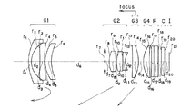
以下、本発明の電子撮像装置に用いられるズームレンズの実施例1〜6について説明する。なお、実施例5〜6は参考例である。これらの実施例の無限遠物点合焦時の広角端でのレンズ断面図をそれぞれ図1〜図6に示す。各図中、第1群はG1、第2群はG2、第3群はG3、第4群はG4、3枚重ねの光学的ローパスフィルターであってその第1面(物体側の表面)に近赤外カットコートが設けられている光学的ローパスフィルターF、電子撮像素子であるCCDのカバーガラスをC、CCDの像面であって補色モザイクフィルターが設けられている像面をIで示してあり、物体側から順に配置された、光学的ローパスフィルターF、カバーガラスCは、第4群G4と像面Iの間に固定して配置されている。なお、また、各図中、フォーカス群は“focus”と図示され、その近距離への合焦方向が矢印で図示してある。
【0082】
実施例1のズームレンズは、図1に示すように、負屈折力の第1群G1、正屈折力の第2群G2、正屈折力の第3群G3、正屈折力の第4群G4からなり、無限遠物点合焦時に広角端から望遠端に変倍する際は、第1群G1は一旦像側へ移動しその後物体側に反転して移動し、望遠端では広角端の位置より物体側になり、第2群G2は物体側に移動し、第3群G3は一旦像側へ若干移動しその後物体側に反転して、望遠端では広角端の位置と同じになり、第4群G4は固定レンズ群であり、第2群G2と第3群G3の間隔は広角端から望遠端に変倍する際に大きくなる。そして、第3群G3を物体側に繰り出して近距離の被写体にフォーカスするようになっている。
【0083】
実施例1の第1群G1は、物体側に凸面を向けた負メニスカスレンズと、両凹レンズと、物体側に凸面を向けた正メニスカスレンズとからなり、第2群G2は、絞りとその後に配置された両凸レンズと、両凸レンズと両凹レンズの接合レンズとからなり、第3群G3は物体側に凹面を向けた正メニスカスレンズ1枚からなり、第4群G4は物体側に凸面を向けた正メニスカスレンズ1枚からなる。非球面は、第1群G1の真中の両凹レンズの物体側の面、第2群G2の最も物体側の面、第4群G4の物体側の面の3面に用いられている。
【0084】
実施例2のズームレンズは、図2に示すように、負屈折力の第1群G1、正屈折力の第2群G2、正屈折力の第3群G3、正屈折力の第4群G4からなり、無限遠物点合焦時に広角端から望遠端に変倍する際は、第1群G1は一旦像側へ移動しその後物体側に反転して移動し、望遠端では広角端の位置より物体側になり、第2群G2は物体側に移動し、第3群G3は物体側に移動し、第4群G4は固定レンズ群であり、第2群G2と第3群G3の間隔は広角端から望遠端に変倍する際に大きくなる。そして、第3群G3を物体側に繰り出して近距離の被写体にフォーカスするようになっている。
【0085】
実施例2の第1群G1は、物体側に凸面を向けた負メニスカスレンズと、両凹レンズと、物体側に凸面を向けた正メニスカスレンズとからなり、第2群G2は、絞りとその後に配置された両凸レンズと、物体側に凸面を向けた正メニスカスレンズと物体側に凸面を向けた負メニスカスレンズの接合レンズとからなり、第3群G3は物体側に凹面を向けた正メニスカスレンズ1枚からなり、第4群G4は物体側に凸面を向けた正メニスカスレンズ1枚からなる。非球面は、第1群G1の真中の両凹レンズの物体側の面、第2群G2の最も物体側の面、第4群G4の物体側の面の3面に用いられている。
【0086】
実施例3のズームレンズは、図3に示すように、負屈折力の第1群G1、正屈折力の第2群G2、正屈折力の第3群G3、正屈折力の第4群G4からなり、無限遠物点合焦時に広角端から望遠端に変倍する際は、第1群G1は一旦像側へ移動しその後物体側に反転して移動し、望遠端では広角端の位置より物体側になり、第2群G2は物体側に移動し、第3群G3は一旦像側へ若干移動しその後物体側に反転して、望遠端では広角端の位置と同じになり、第4群G4は固定レンズ群であり、第2群G2と第3群G3の間隔は広角端から望遠端に変倍する際に大きくなる。そして、第3群G3を物体側に繰り出して近距離の被写体にフォーカスするようになっている。
【0087】
実施例3の第1群G1は、物体側に凸面を向けた負メニスカスレンズと、両凹レンズと、物体側に凸面を向けた正メニスカスレンズとからなり、第2群G2は、絞りとその後に配置された両凸レンズと、両凸レンズと両凹レンズの接合レンズとからなり、第3群G3は物体側に凹面を向けた正メニスカスレンズ1枚からなり、第4群G4は物体側に凸面を向けた正メニスカスレンズ1枚からなる。非球面は、第1群G1の真中の両凹レンズの物体側の面、第2群G2の最も物体側の面、第4群G4の物体側の面の3面に用いられている。
【0088】
実施例4のズームレンズは、図4に示すように、負屈折力の第1群G1、正屈折力の第2群G2、正屈折力の第3群G3、正屈折力の第4群G4からなり、無限遠物点合焦時に広角端から望遠端に変倍する際は、第1群G1は一旦像側へ移動しその後物体側に反転して移動し、望遠端では広角端の位置より若干像側になり、第2群G2は物体側に移動し、第3群G3は一旦像側へ若干移動しその後物体側に反転して、望遠端では広角端の位置と同じになり、第4群G4は固定レンズ群であり、第2群G2と第3群G3の間隔は広角端から望遠端に変倍する際に大きくなる。そして、第3群G3を物体側に繰り出して近距離の被写体にフォーカスするようになっている。
【0089】
実施例4の第1群G1は、両凹レンズと、物体側に凸面を向けた正メニスカスレンズとからなり、第2群G2は、絞りとその後に配置された両凸レンズと、両凸レンズと両凹レンズの接合レンズとからなり、第3群G3は物体側に凹面を向けた正メニスカスレンズ1枚からなり、第4群G4は物体側に凸面を向けた正メニスカスレンズ1枚からなる。非球面は、第1群G1の両凹レンズの像側の面、第2群G2の最も物体側の面、第4群G4の物体側の面の3面に用いられている。
【0090】
実施例5のズームレンズは、図5に示すように、負屈折力の第1群G1、正屈折力の第2群G2、正屈折力の第3群G3、正屈折力の第4群G4からなり、無限遠物点合焦時に広角端から望遠端に変倍する際は、第1群G1は一旦像側へ移動しその後物体側に反転して移動し、望遠端では広角端の位置より若干像側になり、第2群G2は物体側に移動し、第3群G3は一旦像側へ若干移動しその後物体側に反転して、望遠端では広角端の位置と同じになり、第4群G4は固定レンズ群であり、第2群G2と第3群G3の間隔は広角端から望遠端に変倍する際に大きくなる。そして、第3群G3を物体側に繰り出して近距離の被写体にフォーカスするようになっている。
【0091】
実施例5の第1群G1は、物体側に凸面を向けた負メニスカスレンズと、物体側に凸面を向けた正メニスカスレンズとからなり、第2群G2は、絞りとその後に配置された両凸レンズと物体側に凹面を向けた負メニスカスレンズの接合レンズと、物体側に凸面を向けた負メニスカスレンズとからなり、第3群G3は物体側に凹面を向けた正メニスカスレンズ1枚からなり、第4群G4は物体側に凸面を向けた正メニスカスレンズ1枚からなる。非球面は、第1群G1の負メニスカスレンズの像側の面、第2群G2の最も物体側の面、第4群G4の物体側の面の3面に用いられている。
【0092】
実施例6のズームレンズは、図6に示すように、負屈折力の第1群G1、正屈折力の第2群G2、正屈折力の第3群G3、正屈折力の第4群G4からなり、無限遠物点合焦時に広角端から望遠端に変倍する際は、第1群G1は一旦像側へ移動しその後物体側に反転して移動し、望遠端では広角端の位置より若干像側になり、第2群G2は物体側に移動し、第3群G3は一旦物体側へ若干移動しその後像側に反転して、望遠端では広角端の位置より若干物体側になり、第4群G4は固定レンズ群であり、第2群G2と第3群G3の間隔は広角端から望遠端に変倍する際に大きくなる。そして、第3群G3を物体側に繰り出して近距離の被写体にフォーカスするようになっている。
【0093】
実施例6の第1群G1は、物体側に凸面を向けた負メニスカスレンズと、物体側に凸面を向けた正メニスカスレンズとからなり、第2群G2は、絞りとその後に配置された両凸レンズと、物体側に凸面を向けた負メニスカスレンズとからなり、第3群G3は物体側に凸面を向けた正メニスカスレンズ1枚からなり、第4群G4は物体側に凹面を向けた正メニスカスレンズ1枚からなる。非球面は、第1群G1の負メニスカスレンズの像側の面、第2群G2の最も物体側の面、第4群G4の像側の面の3面に用いられている。
【0094】
以下に、上記各実施例の数値データを示すが、記号は上記の外、fは全系焦点距離、ωは半画角、FNOはFナンバー、FBはバックフォーカス、WEは広角端、STは中間状態、TEは望遠端、r1 、r2 …は各レンズ面の曲率半径、d1 、d2 …は各レンズ面間の間隔、nd1、nd2…は各レンズのd線の屈折率、νd1、νd2…は各レンズのアッベ数である。なお、非球面形状は、xを光の進行方向を正とした光軸とし、yを光軸と直交する方向にとると、下記の式にて表される。
【0095】
【0096】
以上の実施例1の無限遠物点合焦時の収差図を図7に示す。この収差図において、(a)は広角端、(b)は中間状態、(c)は望遠端における球面収差SA、非点収差AS、歪曲収差DT、倍率色収差CCを示す。ただし、図中、“FIY”は像高を表している。
【0103】
次に、上記各実施例における条件式(1)〜(8)、(a)、(b)の値を以下に示す。
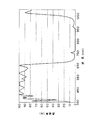
以上の各実施例において、第4群G4の像側には、図示のように、入射面側に近赤外シャープカットコートを施したローパスフィルターFを有している。この近赤外シャープカットコートは、波長600nmでの透過率が80%以上、波長700nmでの透過率が10%以下となるように構成されている。具体的には、例えば次のような27層の層構成からなる多層膜である。ただし、設計波長は780nmである。
【0105】
上記の近赤外シャープカットコートの透過率特性は図8に示す通りである。
【0107】
また、ローパスフィルターFの射出面側には、図9に示すような短波長域の色の透過を低滅する色フィルターを設けるか若しくはコーティングを行うことで、より一層電子画像の色再現性を高めている。
【0108】
具体的には、このフィルター若しくはコーティングにより、波長400nm〜700nmで透過率が最も高い波長の透過率に対する420nmの波長の透過率の比が15%以上であり、その最も高い波長の透過率に対する400nmの波長の透過率の比が6%以下であることが好ましい。
【0109】
それにより、人間の目の色に対する認識と、撮像及び再生される画像の色とのずれを低減させることができる。言い換えると、人間の視覚では認識され難い短波長側の色が、人間の目で容易に認識されることによる画像の劣化を防止することができる。
【0110】
上記の400nmの波長の透過率の比が6%を越えると、人間の目では認識され難い単波長城が認識し得る波長に再生されてしまい、逆に、上記の420nmの波長の透過率の比が15%よりも小さいと、人間の認識し得る波長城の再生が低くなり、色のバランスが悪くなる。
【0111】
このような波長を制限する手段は、補色モザイクフィルターを用いた撮像系においてより効果を奏するものである。
【0112】
上記各実施例では、図9に示すように、波長400nmにおける透過率を0%、420nmにおける透過率を90%、440nmにて透過率のピーク100%となるコーティングとしている。
【0113】
前記した近赤外シャープカットコートとの作用の掛け合わせにより、波長450nmの透過率99%をピークとして、400nmにおける透過率を0%、420nmにおける透過率を80%、600nmにおける透過率を82%、700nmにおける透過率を2%としている。それにより、より忠実な色再現を行っている。
【0114】
また、ローパスフィルターFは、像面上投影時の方位角度が水平(=0°)と±45°方向にそれぞれ結晶軸を有する3種類のフィルターを光軸方向に重ねて使用しており、それぞれについて、水平にaμm、±45°方向にそれぞれSQRT(1/2) ×aだけずらすことで、モアレ抑制を行っている。ここで、SQRTは前記のようにスクエアルートであり平方根を意味する。
【0115】
また、CCDの撮像面I上には、図10に示す通り、シアン、マゼンダ、イエロー、グリーン(緑)の4色の色フィルターを撮像画素に対応してモザイク状に設けた補色モザイクフィルターを設けている。これら4種類の色フィルターは、それぞれが略同じ数になるように、かつ、隣り合う画素が同じ種類の色フィルターに対応しないようにモザイク状に配置されている。それにより、より忠実な色再現が可能となる。
【0116】
補色モザイクフィルターは、具体的には、図10に示すように少なくとも4種類の色フィルターから構成され、その4種類の色フィルターの特性は以下の通りであることが好ましい。
【0117】
グリーンの色フイルターGは波長GP に分光強度のピークを有し、
イエローの色フィルターYe は波長YP に分光強度のピークを有し、
シアンの色フィルターCは波長CP に分光強度のピークを有し、
マゼンダの色フィルターMは波長MP1とMP2にピークを有し、以下の条件を満足する。
【0118】
510nm<GP <540nm
5nm<YP −GP <35nm
−100nm<CP −GP <−5nm
430nm<MP1<480nm
580nm<MP2<640nm
さらに、グリーン、イエロー、シアンの色フィルターはそれぞれの分光強度のピークに対して波長530nmでは80%以上の強度を有し、マゼンダの色フィルターはその分光強度のピークに対して波長530nmの大きい方のピークでは10%から50%の強度を有することが、色再現性を高める上でより好ましい。
【0119】
上記各実施例におけるそれぞれの波長特性の一例を図11に示す。グリーンの色フィルターGは525nmに分光強度のビークを有している。イエローの色フィルターYe は555nmに分光強度のピークを有している。シアンの色フイルターCは510nmに分光強度のピークを有している。マゼンダの色フィルターMは445nmと620nmにピークを有している。また、530nmにおける各色フィルターは、それぞれの分光強度のピークに対して、Gは99%、Ye は95%、Cは97%、Mは38%としている。
【0120】
このような補色フイルターの場合、図示しないコントローラー(若しくは、デジタルカメラに用いられるコントローラー)で、電気的に次のような信号処理を行い、
輝度信号
Y=|G+M+Ye +C|×1/4
色信号
R−Y=|(M+Ye )−(G+C)|
B−Y=|(M+C)−(G+Ye )|
の信号処理を経てR(赤)、G(緑)、B(青)の信号に変換される。
【0121】
ところで、上記した近赤外シャープカットコートの配置位置は、光路上のどの位置であってもよい。また、ローパスフィルターFの枚数も前記した通り2枚でも1枚でも構わない。
【0122】
また、各実施例の明るさ絞りの部分についての詳細を図12示す。撮像光学系の第1群G1と第2群G2との間の光軸上の絞り位置に、0段、−1段、−2段、−3段、−4段の明るさ調節を可能とするターレット10を配置している。ターレット10には、0段の調整をする開口形状が直径約4mmの円形で固定の空間からなる開口1A(波長550nmに対する透過率は100%) と、−1段補正するために開口1Aの開口面積の約半分の開口面積を有する開口形状が固定の透明な平行平板(波長550nmに対する透過率は99%)からなる開口1Bと、開口1Bと同じ面積の円形開口部を有し、−2段、−3段、−4段に補正するため、各々波長550nmに対する透過率が50%、25%、13%のNDフィルターが設けられた開口部1C、1D、1Eとを有している。
【0123】
そして、ターレット10の回転軸11の周りの回動により何れかの開口を絞り位置に配することで光量調節を行っている。
【0124】
また、実効FナンバーFno' がFno' >a/0.4μmとなるときに、開口内に波長550nmに対する透過率が80%未満のNDフィルターが配される構成としている。具体的には、実施例1では、望遠端の実効F値が上記式を満たすのは、絞り開放時(0段)に対して−2段とした実行F値が9.0となるときであり、そのときに対応する開口は1Cとなる。それにより、絞りの回折現象による像の劣化を抑えている。
【0125】
また、図12に示すターレット10に代えて、図13(a)に示すターレット10’を用いた例を示す。撮像光学系の第1群G1と第2群G2との間の光軸上の明るさ絞り位置に、0段、−1段、−2段、−3段、−4段の明るさ調節を可能とするターレット10’を配置している。ターレット10’には、0段の調整をする開口形状が直径約4mmの円形で固定の開口1A' と、−1段補正するために開口1A’の開口面積の約半分の開口面積を有する開口形状が固定の開口1B' と、さらに開口面積が順に小さくなり、−2段、−3段、−4段に補正するための形状が固定の開口部1C' 、1D' 、1E' とを有している。そして、ターレット10’の回転軸11の周りの回動により何れかの開口を絞り位置に配することで光量調節を行っている。
【0126】
また、これら複数の開口の中の1A' から1D' にそれぞれ空間周波数特性の異なる光学的ローパスフィルターを配している。そして、図13(b)に示すように、開口径が小さくなる程光学フィルターの空間周波数特性を高く設定しており、それにより絞り込むことによる回折現象による像の劣化を抑えている。なお、図13(b)の各曲線は、ローパスフィルターのみの空間周波数特性を示すものであり、各絞りの回折も含めた特性は何れも等しくなるように設定しているものである。
【0127】
さて、以上のような本発明の電子撮像装置は、ズームレンズで物体像を形成しその像をCCDや銀塩フィルムといった撮像素子に受光させて撮影を行う撮影装置、とりわけデジタルカメラやビデオカメラ、情報処理装置の例であるパソコン、電話、特に持ち運びに便利な携帯電話等に用いることができる。以下に、その実施形態を例示する。
【0128】
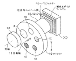
図14〜図16は、本発明によるのズームレンズをデジタルカメラの撮影光学系41に組み込んだ構成の概念図を示す。図14はデジタルカメラ40の外観を示す前方斜視図、図15は同後方斜視図、図16はデジタルカメラ40の構成を示す断面図である。デジタルカメラ40は、この例の場合、撮影用光路42を有する撮影光学系41、ファインダー用光路44を有するファインダー光学系43、シャッター45、フラッシュ46、液晶表示モニター47等を含み、カメラ40の上部に配置されたシャッター45を押圧すると、それに連動して撮影光学系41、例えば実施例1のズームレンズを通して撮影が行われる。撮影光学系41によって形成された物体像が、近赤外カットコートを設けた光学的ローパスフィルターFを介してCCD49の撮像面上に形成される。このCCD49で受光された物体像は、処理手段51を介し、電子画像としてカメラ背面に設けられた液晶表示モニター47に表示される。また、この処理手段51には記録手段52が接続され、撮影された電子画像を記録することもできる。なお、この記録手段52は処理手段51と別体に設けてもよいし、フロッピーディスクやメモリーカード、MO等により電子的に記録書込を行うように構成してもよい。また、CCD49に代わって銀塩フィルムを配置した銀塩カメラとして構成してもよい。
【0129】
さらに、ファインダー用光路44上にはファインダー用対物光学系53が配置してある。このファインダー用対物光学系53によって形成された物体像は、像正立部材であるポロプリズム55の視野枠57上に形成される。このポリプリズム55の後方には、正立正像にされた像を観察者眼球Eに導く接眼光学系59が配置されている。なお、撮影光学系41及びファインダー用対物光学系53の入射側、接眼光学系59の射出側にそれぞれカバー部材50が配置されている。
【0130】
このように構成されたデジタルカメラ40は、撮影光学系41が広画角で高変倍比であり、収差が良好で、明るく、フィルター等が配置できるバックフォーカスの大きなズームレンズであるので、高性能・低コスト化が実現できる。
【0131】
なお、図16の例では、カバー部材50として平行平面板を配置しているが、パワーを持ったレンズを用いてもよい。
【0132】
次に、本発明のズームレンズが対物光学系として内蔵された情報処理装置の一例であるパソコンが図17〜図19に示される。図17はパソコン300のカバーを開いた前方斜視図、図18はパソコン300の撮影光学系303の断面図、図19は図17の状態の側面図である。図17〜図19に示されるように、パソコン300は、外部から繰作者が情報を入力するためのキーボード301と、図示を省略した情報処理手段や記録手段と、情報を操作者に表示するモニター302と、操作者自身や周辺の像を撮影するための撮影光学系303とを有している。ここで、モニター302は、図示しないバックライトにより背面から照明する透過型液晶表示素子や、前面からの光を反射して表示する反射型液晶表示素子や、CRTディスプレイ等であってよい。また、図中、撮影光学系303は、モニター302の右上に内蔵されているが、その場所に限らず、モニター302の周囲や、キーボード301の周囲のどこであってもよい。
【0133】
この撮影光学系303は、撮影光路304上に、本発明によるズームレンズ(図では略記)からなる対物レンズ112と、像を受光する撮像素子チップ162とを有している。これらはパソコン300に内蔵されている。
【0134】
ここで、撮像素子チップ162上には光学的ローパスフィルターFが付加的に貼り付けられて撮像ユニット160として一体に形成され、対物レンズ112の鏡枠113の後端にワンタッチで嵌め込まれて取り付け可能になっているため、対物レンズ112と撮像素子チップ162の中心合わせや面間隔の調整が不要であり、組立が簡単となっている。また、鏡枠113の先端には、対物レンズ112を保護するためのカバーガラス114が配置されている。なお、鏡枠113中のズームレンズの駆動機構は図示を省いてある。
【0135】
撮像素子チップ162で受光された物体像は、端子166を介して、パソコン300の処理手段に入力され、電子画像としてモニター302に表示される、図17には、その一例として、操作者の撮影された画像305が示されている。また、この画像305は、処理手段を介し、インターネットや電話を介して、遠隔地から通信相手のパソコンに表示されることも可能である。
【0136】
次に、本発明のズームレンズが撮影光学系として内蔵された情報処理装置の一例である電話、特に持ち運びに便利な携帯電話が図20に示される。図20(a)は携帯電話400の正面図、図20(b)は側面図、図20(c)は撮影光学系405の断面図である。図20(a)〜(c)に示されるように、携帯電話400は、操作者の声を情報として入力するマイク部401と、通話相手の声を出力するスピーカ部402と、操作者が情報を入力する入力ダイアル403と、操作者自身や通話相手等の撮影像と電話番号等の情報を表示するモニター404と、撮影光学系405と、通信電波の送信と受信を行うアンテナ406と、画像情報や通信情報、入力信号等の処理を行う処理手段(図示せず)とを有している。ここで、モニター404は液晶表示素子である。また、図中、各構成の配置位置は、特にこれらに限られない。この撮影光学系405は、撮影光路407上に配置された本発明によるズームレンズ(図では略記)からなる対物レンズ112と、物体像を受光する撮像素子チップ162とを有している。これらは、携帯電話400に内蔵されている。
【0137】
ここで、撮像素子チップ162上には光学的ローパスフィルターFが付加的に貼り付けられて撮像ユニット160として一体に形成され、対物レンズ112の鏡枠113の後端にワンタッチで嵌め込まれて取り付け可能になっているため、対物レンズ112と撮像素子チップ162の中心合わせや面間隔の調整が不要であり、組立が簡単となっている。また、鏡枠113の先端には、対物レンズ112を保護するためのカバーガラス114が配置されている。なお、鏡枠113中のズームレンズの駆動機構は図示を省いてある。
【0138】
撮影素子チップ162で受光された物体像は、端子166を介して、図示していない処理手段に入力され、電子画像としてモニター404に、又は、通信相手のモニターに、又は、両方に表示される。また、通信相手に画像を送信する場合、撮像素子チップ162で受光された物体像の情報を、送信可能な信号へと変換する信号処理機能が処理手段には含まれている。
【0139】
以上の本発明の電子撮像装置は例えば次のように構成することができる。
【0140】
〔1〕 結像光学系と前記結像光学系の像側に配された電子撮像素子とを備えた電子撮像装置において、
前記結像光学系は、非球面を含みかつ常時固定である最も像側の最終レンズと、前記最終レンズより物体側直前に配され、かつ、フォーカスのために移動するフォーカスレンズ群とを含むことを特徴とする電子撮像装置。
【0141】
〔2〕 前記結像光学系は、広角端から望遠端にかけて変倍する際に物体側にのみ移動する正の屈折力のレンズ群を有することを特徴とする上記1記載の電子撮像装置。
【0142】
〔3〕 前記結像光学系は、物体側から順に、負の屈折力の第1レンズ群、広角端から望遠端にかけて変倍する際に物体側にのみ移動する正の屈折力の第2レンズ群を有することを特徴とする上記1又は2記載の電子撮像装置。
【0143】
〔4〕 前記結像光学系は、物体側から順に、負の屈折力の第1レンズ群、広角端から望遠端にかけて変倍する際に物体側にのみ移動する複数の正の屈折力のレンズ群を有することを特徴とする上記1又は2記載の電子撮像装置。
【0144】
〔5〕 結像光学系と前記結像光学系の像側に配された電子撮像素子とを備えた電子撮像装置において、
前記結像光学系は、最も物体側に配された負の屈折力を有する第1レンズ群と、その像側に配された少なくとも3つのレンズ群とを含み、
物体側より引き続く4つ目のレンズ群までの相互の間隔は、変倍あるいはフォーカスのために変化し、
最も像側のレンズ群は固定で1枚の非球面レンズにて構成され、
変倍時に前記第1レンズ群の像側直後のレンズ群と一体で移動する開口絞りを有することを特徴とする電子撮像装置。
【0145】
〔6〕 ズームレンズと前記ズームレンズの像側に配された電子撮像素子とを備えた電子撮像装置において、
前記ズームレンズは、物体側より順に、負の屈折力を有する第1レンズ群と、正の屈折力を有する第2レンズ群と、正の屈折力を有する第3レンズ群と、第4レンズ群からなり、
前記第3レンズ群を物体側に繰り出すことでより近距離の被写体に合焦することが可能であり、
前記第4レンズ群が非球面を含む常時固定の1枚のレンズよりなることを特徴とする電子撮像装置。
【0146】
〔7〕 ズームレンズと前記ズームレンズの像側に配された電子撮像素子とを備えた電子撮像装置において、
前記ズームレンズは、物体側より順に、負の屈折力を有する第1レンズ群と、正の屈折力を有する第2レンズ群と、正の屈折力を有する第3レンズ群と、第4レンズ群からなり、
前記第3レンズ群を物体側に繰り出すことでより近距離の被写体に合焦することが可能であり、
前記第2レンズ群は、非球面を含む1枚の単レンズと、物体側より順に正レンズと負レンズとからなる接合レンズとからなり、
前記第3レンズ群は、正の単レンズ1枚よりなることを特徴とする電子撮像装置。
【0147】
〔8〕 ズームレンズと前記ズームレンズの像側に配された電子撮像素子とを備えた電子撮像装置において、
前記ズームレンズは、物体側より順に、負の屈折力を有する第1レンズ群と、正の屈折力を有する第2レンズ群と、正の屈折力を有する第3レンズ群と、第4レンズ群とからなり、
前記第3レンズ群を物体側に繰り出すことでより近距離の被写体に合焦することが可能であり、
前記第2レンズ群は、非球面を含む1つの正レンズと、1つの負レンズとからなり、
前記第3レンズ群は、正の単レンズ1枚よりなることを特徴とする電子撮像装置。
【0148】
〔9〕 前記第1レンズ群が変倍時移動することを特徴とする上記1から8の何れか1項記載の電子撮像装置。
【0149】
〔10〕 最も物体側に、負の屈折力を有する第1群を有し、4つ以上の群より構成され、物体側より4つ目までの群は変倍中に相互の間隔が変化し、最も像側の群は固定で正の屈折力を有する1枚の非球面単レンズにて構成され、変倍時に第2群と一体で移動する開口絞りを有し、かつ、以下の条件(1)を満足するズームレンズ及び電子撮像素子を有することを特徴とする電子撮像装置。
【0150】
(1) 1.5<L2 /Y<3.5
ただし、L2 は第2群の広角端から望遠端にかけての移動量、Yは撮像素子の有効撮像領域の対角長である。
【0151】
〔11〕 物体側より順に、負の屈折力を有する第1群と正の屈折力を有する第2群と正の屈折力を有する第3群と正の屈折力を有する第4群とよりなり、無限遠物点合焦時に広角端から望遠端に変倍する際は、前記第2群と第3群の間隔が大きくなり、前記第3群を物体側に繰り出すことでより近距離の被写体に合焦することが可能であり、前記第4群は正の屈折力を有する1枚の非球面単レンズにて構成され、以下の条件(2)を満足するズームレンズ及び電子撮像素子を有することを特徴とする電子撮像装置。
【0152】
(2) −1.2<exPW /exPT <0
ただし、exPW 、exPT はそれぞれ無限遠物点合焦時における広角端及び望遠端での像面から測った射出瞳位置である。
【0153】
〔12〕 物体側より順に、負の屈折力を有する第1群と正の屈折力を有する第2群と正の屈折力を有する第3群と正の屈折力を有する第4群とよりなり、無限遠物点合焦時に広角端から望遠端に変倍する際は、前記第2群と第3群の間隔が大きくなり、前記第3群を物体側に繰り出すことでより近距離の被写体に合焦することが可能であり、前記第2群が物体側から順に非球面を含む1枚の単レンズと物体側から正レンズ、負レンズの順で構成した接合レンズとからなり、前記第3群は正の屈折力を有する1枚の単レンズよりなり、以下の条件(3)と条件(4)を満足するズームレンズ及び電子撮像素子を有することを特徴とする電子撮像装置。
【0154】
【0155】
〔13〕 物体側より順に、負の屈折力を有する第1群と正の屈折力を有する第2群と正の屈折力を有する第3群と正の屈折力を有する第4群よりなり、無限遠物点合焦時に広角端から望遠端に変倍する際は、前記第2群と第3群の間隔が大きくなり、前記第3群を物体側に繰り出すことでより近距離の被写体に合焦することが可能であり、前記第2群が物体側から順に非球面を含む正レンズ成分と負レンズ成分1つずつからなり、前記第3群は正の屈折力を有する1枚の単レンズよりなり、以下の条件(5)を満足するズームレンズ及び電子撮像素子を有することを特徴とする電子撮像装置。
【0156】
(5) 0.05<t2NI /t2 <0.3
ただし、t2NI は第2群中の最も像側の負レンズの光軸上での厚み、t2 は第2群の最も物体側の面から最も像側の面までの光軸上での厚みである。
【0157】
〔14〕 前記第1群は、物体側から順に、2枚の負レンズからなる負レンズ群と1枚の正レンズからなる正レンズ群とよりなることを特徴とする上記10から13の何れか1項記載の電子撮像装置。
【0158】
〔15〕 前記第1群は、物体側から順に、2枚以下の負レンズからなる負レンズ群と1枚の正レンズからなる正レンズ群とよりなり、前記負レンズ群の中少なくとも1枚の負レンズは非球面を含むことを特徴とする上記10から13の何れか1項記載の電子撮像装置。
【0159】
〔16〕 前記第1群、第2群の各々の総厚が以下の条件(6)、(7)を満足することを特徴とする上記9から15の何れか1項記載の電子撮像装置。
【0160】
(6) 0.6<t1 /Y<2.2
(7) 0.3<t2 /Y<1.5
ただし、t1 は第1群の最も物体側の面から最も像側の面までの光軸上での厚みであり、t2 は第2群の最も物体側の面から最も像側の面までの光軸上での厚みであり、Yは撮像素子の有効撮像領域の対角長である。
【0161】
〔17〕 前記ズームレンズの後方にある撮像素子よりも物体側に、波長600nmでの透過率が80%以上であり、波長700nmでの透過率が10%以下である近赤外シャープカットコートを有することを特徴とする上記9から16の何れか1項記載の電子撮像装置。
【0162】
〔18〕 前記撮像素子が、カラー化フィルターとして補色モザイクフィルターを有することを特徴とする上記17記載の電子撮像装置。
【0163】
〔19〕 前記補色モザイクフィルターは少なくとも4種類の色フィルターからなり、それぞれが略同じ数になるように、かつ、隣り合う画素が同じ種類の色フィルターに対応しないようにモザイク状に配置されていることを特徴とする上記18記載の電子撮像装置。
【0164】
〔20〕 前記補色モザイクフィルターは少なくとも4種類の色フィルターから構成され、前記4種類の色フィルターの特性は以下の通りであることを特徴とする上記18又は19記載の電子撮像装置。
【0165】
グリーンの色フイルターGは波長GP に分光強度のピークを有し、
イエローの色フィルターYe は波長YP に分光強度のピークを有し、
シアンの色ブィルターCは波長CP に分光強度のピークを有し、
マゼンダの色フィルターMは波長MP1とMP2にピークを有し、以下の条件を満足する。
【0166】
510nm<GP <540nm
5nm<YP −GP <35nm
−100nm<CP −GP <−5nm
430nm<MP1<480nm
580nm<MP2<640nm
〔21〕 前記グリーン、イエロー、シアンの色フィルターはそれぞれの分光強度のピークに対して530nmでは80%以上の強度を有し、前記マゼンダの色フィルターはその分光強度のピークに対して波長530nmの大きい方のピークでは10%から50%の強度を有することを特徴とする上記20記載のの電子撮像装置。
【0167】
〔22〕 前記撮像素子より物体側に光軸上の総厚tLPF が以下の条件(8)を満たす光学的ローパスフィルターを配したことを特徴とする上記10から21の何れか1項記載の電子撮像装置。
【0168】
(8) 0.15×10³ <tLPF /a<0.45×103
ただし、aは電子撮像素子の水平画素ピッチである。
【0169】
〔23〕 開口形状が固定の複数の開口を有し、その中の1つ開口を前記第1群の最も像側の面と前記第3群の最も物体側の面の間の何れかの光路内に挿入可能であり、かつ、他の開口と入れ替え可能とすることで像面照度の調節を行うことを特徴とする上記10から22の何れか1項記載の電子撮像装置。
【0170】
〔24〕 前記複数の開口の中、一部の開口内に波長550nmに対する透過率が80%未満の媒体を有すると共に、他の一部の開口の波長550nmに対する透過率を80%以上としたことを特徴とする上記23記載の電子撮像装置。
【0171】
〔25〕 ズームレンズの焦点距離と入射瞳の直径から求まるFナンバーをFno、前記開口における波長550nmにおける透過率をTとしたときのFno/√Tを実効FナンバーFno' とし、電子撮像素子の水平画素ピッチをaとするとき、Fno' >a/0.4μmとなるような実効Fナンバーに相当する光量になるように調節を実施する場合は、開口内に波長550nmに対する透過率Tが80%未満の媒体を備えた開口を前記ズームレンズの光路に挿入することを特徴とする上記23記載の電子撮像装置。
【0172】
〔26〕 前記複数の開口の中の複数にそれぞれ空間周波数特性の異なる光学的ローパスフィルターを有することを特徴とする上記23から25の何れか1項記載の電子撮像装置。
【0173】
以上の説明から明らかなように、本発明によると、物体側より順に、負の屈折力を有する第1レンズ群と、広角端から望遠端にかけて変倍する際に物体側にのみ移動する正の屈折力を有する第2レンズ群と、正の屈折力を有する第3レンズ群と、第4レンズ群からなるズームレンズを有する電子撮像装置において、第4レンズ群の構成枚数が少なく、リアフォーカス方式により、機構レイアウト上小型で簡素にしやすく、変倍比を確保しても薄型化と諸収差の補正を両立させることが可能となる。
【図面の簡単な説明】
【図1】本発明の電子撮像装置に用いられるズームレンズの実施例1の無限遠物点合焦時の広角端でのレンズ断面図である。
【図2】実施例2のズームレンズの図1と同様のレンズ断面図である。
【図3】実施例3のズームレンズの図1と同様のレンズ断面図である。
【図4】実施例4のズームレンズの図1と同様のレンズ断面図である。
【図5】実施例5のズームレンズの図1と同様のレンズ断面図である。
【図6】実施例6のズームレンズの図1と同様のレンズ断面図である。
【図7】実施例1の無限遠物点合焦時の収差図である。
【図8】近赤外シャープカットコートの一例の透過率特性を示す図である。
【図9】ローパスフィルターの射出面側に設ける色フィルターの一例の透過率特性を示す図である。
【図10】補色モザイクフィルターの色フィルター配置を示す図である。
【図11】補色モザイクフィルターの波長特性の一例を示す図である。
【図12】各実施例の明るさ絞りの部分の一例の詳細を示す斜視図である。
【図13】各実施例の明るさ絞りの部分の別の例の詳細を示す図である。
【図14】本発明によるズームレンズを組み込んだデジタルカメラの外観を示す前方斜視図である。
【図15】図14のデジタルカメラの後方斜視図である。
【図16】図14のデジタルカメラの断面図である。
【図17】本発明によるズームレンズが対物光学系として組み込れたパソコンのカバーを開いた前方斜視図である。
【図18】パソコンの撮影光学系の断面図である。
【図19】図17の状態の側面図である。
【図20】本発明によるズームレンズが対物光学系として組み込れた携帯電話の正面図、側面図、その撮影光学系の断面図である。
【符号の説明】
G1…第1群
G2…第2群
G3…第3群
G4…第4群
F…光学的ローパスフィルター
C…カバーガラス
I…像面
E…観察者眼球
1A、1B、1C、1D、1E…開口
1A’、1B’、1C’、1D’、1E’…開口
10…ターレット
10’…ターレット
11…回転軸
40…デジタルカメラ
41…撮影光学系
42…撮影用光路
43…ファインダー光学系
44…ファインダー用光路
45…シャッター
46…フラッシュ
47…液晶表示モニター
49…CCD
50…カバー部材
51…処理手段
52…記録手段
53…ファインダー用対物光学系
55…ポロプリズム
57…視野枠
59…接眼光学系
112…対物レンズ
113…鏡枠
114…カバーガラス
160…撮像ユニット
162…撮像素子チップ
166…端子
300…パソコン
301…キーボード
302…モニター
303…撮影光学系
304…撮影光路
305…画像
400…携帯電話
401…マイク部
402…スピーカ部
403…入力ダイアル
404…モニター
405…撮影光学系
406…アンテナ
407…撮影光路[0001]
BACKGROUND OF THE INVENTION
The present invention relates to an electronic imaging apparatus that is thin in the depth direction by devising an optical system portion such as a zoom lens, and more particularly to a video camera and a digital camera. In addition, the zoom lens enables rear focus.
[0002]
[Prior art]
In recent years, digital cameras (electronic cameras) have attracted attention as next-generation cameras that replace silver salt 35 mm film (commonly known as Leica version) cameras. Furthermore, it has come to have a number of categories in a wide range from a high-function type for business use to a portable popular type. The present invention pays attention to the category of portable popular types in particular, and aims to provide a technology for realizing a video camera and a digital camera with a thin depth while ensuring high image quality. The biggest bottleneck in reducing the depth direction of the camera is the thickness from the most object-side surface to the imaging surface of the optical system, particularly the zoom lens system. Recently, it has become a mainstream to employ a so-called collapsible lens barrel that projects an optical system from the camera body during shooting and stores the optical system in the camera body when carried. However, the thickness when the optical system is retracted varies greatly depending on the lens type and filter used. In particular, in order to set high specifications such as zoom ratio and F value, the so-called positive leading zoom lens in which the lens unit closest to the object side has positive refractive power has a large thickness and dead space of each lens element, so Even so, the thickness is not reduced (Japanese Patent Laid-Open No. 11-258507). The negative leading type, especially the zoom lens having 2 to 3 groups, is advantageous in this respect, but it is retracted even when the number of elements in the group is large, the thickness of the element is large, or the most object side lens is a positive lens. However, it does not become thin (Japanese Patent Laid-Open No. 11-52246). Among the currently known examples, those suitable for electronic imaging devices and having good imaging performance including zoom ratio, angle of view, F number, etc., and the possibility of making the collapsible thickness the thinnest are disclosed in JP-A-11 No. 194274, JP-A-11-287953, JP-A-2000-9997, and the like.
[0003]
In order to make the first group thinner, it is preferable to make the entrance pupil position shallower. For this purpose, the magnification of the second group is increased. On the other hand, this not only increases the burden on the second group and makes it difficult to reduce the thickness of the second group, but also increases the difficulty of aberration correction and the effect of manufacturing errors. In order to reduce the thickness and size of the image sensor, it is only necessary to reduce the size of the image sensor. However, in order to obtain the same number of pixels, it is necessary to reduce the pixel pitch, and the lack of sensitivity must be covered by the optical system. The same is true for diffraction.
[0004]
Also, in order to make the camera body thin, so-called rear focus is effective for the layout of the drive system instead of the front group for lens movement during focusing. Then, it becomes necessary to select an optical system with less aberration fluctuation when rear focus is performed.
[0005]
[Problems to be solved by the invention]
An object of the present invention is, in order from the object side, a first lens group having negative refractive power, and a second lens group having positive refractive power that moves only to the object side when zooming from the wide-angle end to the telephoto end. In the electronic imaging device having the third lens group having positive refractive power and the zoom lens composed of the fourth lens group, the number of the fourth lens group is small, and the rear focus system is used to reduce the size and the mechanism layout. It is easy to reduce the thickness and correct various aberrations even if the zoom ratio is secured.
[0006]
[Means for Solving the Problems]
In order to achieve the above object, an electronic imaging apparatus of the present invention includes an imaging optical system and an electronic imaging device arranged on the image side of the imaging optical system.
The imaging optical system includes a final lens group closest to the image side that is a single lens that includes an aspherical surface and is always fixed, and a focus lens that is disposed immediately before the object side from the final lens group and moves for focusing It is characterized by including a group.
[0007]
In this case, it is desirable that the imaging optical system has a lens unit having a positive refractive power that moves only to the object side when zooming from the wide-angle end to the telephoto end.
[0008]
The imaging optical system includes, in order from the object side, a first lens group having a negative refractive power, and a second lens group having a positive refractive power that moves only to the object side when zooming from the wide-angle end to the telephoto end. It can have.
[0009]
The imaging optical system includes, in order from the object side, a first lens group having a negative refractive power, and a plurality of lens groups having a positive refractive power that move only to the object side when zooming from the wide-angle end to the telephoto end. It can have.
[0010]
Another electronic imaging device of the present invention is an electronic imaging device comprising an imaging optical system and an electronic imaging device disposed on the image side of the imaging optical system.
The imaging optical system includes a first lens group having a negative refractive power arranged on the most object side, and at least three lens groups arranged on the image side,
The mutual distance from the object side to the fourth lens group that follows is changed due to zooming or focusing.
The last lens group on the most image side is fixed and is composed of one aspheric lens,
The zoom lens has an aperture stop that moves together with the lens group immediately after the image side of the first lens group at the time of zooming.
[0011]
Yet another electronic imaging device of the present invention is an electronic imaging device comprising a zoom lens and an electronic imaging device arranged on the image side of the zoom lens.
The zoom lens includes, in order from the object side, a first lens group having a negative refractive power, a second lens group having a positive refractive power, a third lens group having a positive refractive power, and a fourth lens group. Consists of
It is possible to focus on a closer subject by extending the third lens group toward the object side,
The fourth lens group is composed of one lens that is always fixed including an aspherical surface.
[0012]
Another electronic imaging device of the present invention is an electronic imaging device comprising a zoom lens and an electronic imaging device disposed on the image side of the zoom lens.
The zoom lens includes, in order from the object side, a first lens group having a negative refractive power, a second lens group having a positive refractive power, a third lens group having a positive refractive power, and a fourth lens group. Consists of
It is possible to focus on a closer subject by extending the third lens group toward the object side,
The second lens group includes a single lens including an aspheric surface and a cemented lens including a positive lens and a negative lens in order from the object side.
The third lens group comprises a single positive single lens.
[0013]
Still another electronic imaging device of the present invention is an electronic imaging device comprising a zoom lens and an electronic imaging device arranged on the image side of the zoom lens.
The zoom lens includes, in order from the object side, a first lens group having a negative refractive power, a second lens group having a positive refractive power, a third lens group having a positive refractive power, and a fourth lens group. And consist of
It is possible to focus on a closer subject by extending the third lens group toward the object side,
The second lens group includes one positive lens including an aspherical surface and one negative lens.
The third lens group comprises a single positive single lens.
[0014]
In the above, the first lens group can be moved during zooming.
[0015]
In the imaging optical system employed in the electronic image pickup apparatus of the present invention, the lens closest to the image (single lens or cemented lens) includes an aspherical surface, which is always fixed, and the lens group immediately before this moves for focusing. This is a rear focus type zoom lens. Therefore, it is possible to ensure a stable and high imaging performance from infinity to a short distance while using the rear focus method. This is particularly effective when a lens unit having a positive refractive power that moves monotonously on the object side when zooming from the wide-angle end to the telephoto end is effective. In a zoom lens having such a lens group, an aspherical surface is introduced in the final group in order to reduce aberration fluctuations in the entire zooming range from the wide-angle end to the telephoto end, and to correct aberrations in a small amount in any state. In particular, correction of off-axis aberrations such as coma and astigmatism is performed. Therefore, when focusing is performed on the final group having an aspheric surface, fluctuations in off-axis aberrations such as coma and astigmatism accompanying movement in the optical axis direction are likely to increase, leading to performance degradation. For this reason, it is preferable that the final group having an aspheric surface is fixed, and focusing is performed in the group immediately before that.
[0016]
Note that the first lens group of such a zoom lens is more compact when it is constituted by a negative lens group, but the above problem is more conspicuous than when the first lens group is a positive lens group.
[0017]
For example, specifically, in order from the object side, a first lens group having a negative refractive power, a second lens group having a positive refractive power, a third lens group having a positive refractive power, and a fourth lens group. An imaging optical system that includes a lens group and includes a zoom lens that can focus on an object at a shorter distance by extending the third lens group toward the object side, and the fourth lens group includes an aspherical surface An imaging optical system composed of a single lens with a fixed position, or a first lens group having a negative refractive power, a second lens group having a positive refractive power, and a positive refractive power in order from the object side. A zoom lens that includes a third lens group and a fourth lens group, and is capable of focusing on a subject at a closer distance by extending the third lens group toward the object side. Including a single lens and a single positive / negative lens The third lens group is composed of a single lens and an imaging optical system consisting of a single positive lens, or a first lens group having a negative refractive power and a first lens group having a positive refractive power in order from the object side. A zoom lens that includes two lens groups, a third lens group having positive refractive power, and a fourth lens group, and is capable of focusing on an object at a shorter distance by extending the third lens group to the object side. The second lens group is composed of one positive lens (single lens or cemented lens) including an aspheric surface and one negative lens (single lens or cemented lens), and the third lens group is composed of one positive lens that is a single lens. This is the case with an imaging optical system.
[0018]
In addition, it is more preferable that the fourth lens group which is the final lens group has a positive refractive power because the incident angle to the electronic imaging element can be made nearly vertical. In order to reduce the number of parts, this lens group can be an aspherical single lens.
[0019]
As described above, in the group movable during zooming, the aberration variation in the entire zooming range is corrected as much as possible to remove substantially uniform aberrations, particularly off-axis aberrations, by adding an aspheric surface to the final lens group. Yes. However, especially in the case of coma aberration, correction cannot be made unless the lens surface for correction is separated from the image plane to some extent. Therefore, the air conversion distance DR on the optical axis between the last lens group and the image plane should satisfy the following condition.
[0020]
(X) 0.3 <DR / Y <2.5
However, Y is the diagonal length of the effective imaging area (substantially rectangular) of an image sensor.
[0021]
When the lower limit of 0.3 of the condition (x) is exceeded, correction of distortion due to the aspherical surface of the final lens group is easy, but correction of coma becomes difficult. When the upper limit of 2.5 is exceeded, the total length of the optical system and the lens diameter of the group apart from the aperture stop tend to be enlarged.
[0022]
Moreover,
(X-1) 0.4 <DR / Y <2.0
It is more preferable.
[0023]
In addition,
(X-2) 0.5 <DR / Y <1.5
It is more preferable.
[0024]
In order to cover as much as possible the space loss caused by the above-described configuration, the distance D between the last lens group including the aspheric surface and the fixed last lens group and the focus group immediately before it is D.34W(However, it is better to satisfy the following conditions for the wide-angle end when focusing on an object point at infinity).
[0025]
(Y) 0.05 <D34W/Y<0.8
If the upper limit of 0.8 of the condition (y) is exceeded, the total length of the optical system tends to be long or it is difficult to ensure a zoom ratio. The lower limit of 0.05 is provided to avoid mechanical interference between the two groups.
[0026]
Moreover,
(Y-1) 0.05 <D34W/Y<0.6
It is more preferable.
[0027]
In addition,
(Y-2) 0.05 <D34W/Y<0.4
It is more preferable.
[0028]
Further, by making the first lens group, which is the most object side lens group, movable with zooming, the first lens group can have the function of a compensator. Since ratio can be expanded, it is more preferable.
[0029]
Next, an invention to which the above invention is applied will be described.
[0030]
In order to achieve the above object, another electronic imaging apparatus of the present invention has a first group having a negative refractive power closest to the object side, is composed of four or more groups, and a fourth group from the object side. The distance between the two groups changes during zooming, and the most image side group is composed of a single aspherical single lens having a fixed positive refractive power, and is integrated with the second group during zooming. It has a zoom lens and an electronic image sensor characterized by having a moving aperture stop and satisfying the following condition (1).
[0031]
(1) 1.5 <L2/Y<3.5
However, L2Is the amount of movement of the second group from the wide-angle end to the telephoto end, and Y is the diagonal length of the effective image pickup area (substantially rectangular) of the image sensor.
[0032]
The configuration of the zoom lens as in the present invention is easy to reduce the thickness of each group and is simple in configuration, and also has stable imaging performance during zooming and focusing. In addition, there is little fluctuation in the F value due to zooming. However, there is a drawback that the variation of the exit pupil position is large. This is because the amount of movement of the diaphragm during zooming is large. Exceeding the upper limit 3.5 of condition (1) is not preferable because the angle of the principal ray on the imaging surface becomes too large at the wide-angle end or the telephoto end. If the lower limit of 1.5 is exceeded, aberration fluctuations such as astigmatism during zooming or focusing tend to increase, which is not preferable.
[0033]
In addition, it is more preferable to replace the condition (1) as follows.
[0034]
(1-1) 1.6 <L2/Y<3.3
Furthermore, the following is more preferable.
[0035]
(1-2) 1.7 <L2/Y<3.0
It is also preferable to individually limit the lower limit value or the upper limit value of the above formula.
[0036]
In the present invention, the first group having a negative refractive power, the second group having a positive refractive power, the third group having a positive refractive power, and the fourth group having a positive refractive power in order from the object side. When zooming from the wide-angle end to the telephoto end when focusing on an object point at infinity, the distance between the second group and the third group becomes larger, and the third group is moved closer to the object side. It is possible to focus on a subject at a distance, and the fourth group includes a single aspherical single lens having a positive refractive power, and satisfies the following condition (2) and electronic imaging An electronic imaging device including an element may be used.
[0037]
(2) -1.2 <exPW/exPT<0
However,exPW,exPTAre respectively the exit pupil positions measured from the image planes at the wide-angle end and the telephoto end when focusing on an object point at infinity.
[0038]
In the case of this zoom method, since the amount of change in the exit pupil position is large from the wide angle to the telephoto, it is necessary to be within the condition (2). When the upper limit of 0 is exceeded, shading tends to occur at the wide-angle end, and when the lower limit of −1.2 is exceeded, shading tends to occur at the telephoto end.
[0039]
In addition, it is better if it is as follows.
[0040]
(2-1) -1.1 <exPW/exPT<-0.2
Furthermore, it is even better to do the following.
[0041]
(2-2) -1.0 <exPW/exPT<-0.4
It is also preferable to individually limit the lower limit value or the upper limit value of the above formula.
[0042]
In the present invention, in order from the object side, a first group having a negative refractive power, a second group having a positive refractive power, a third group having a positive refractive power, and a fourth group having a positive refractive power. When zooming from the wide-angle end to the telephoto end when focusing on an object point at infinity, the distance between the second group and the third group becomes larger, and the third group is moved closer to the object side. It is possible to focus on an object at a distance, and the second group includes a single lens including an aspheric surface in order from the object side, and a cemented lens configured in this order from the object side to a positive lens and a negative lens. The third group is composed of one single lens having a positive refractive power, and has a zoom lens and an electronic image sensor that satisfy the following conditions (3) and (4): It is good.
[0043]
[0044]
Condition (3) defines the ratio of the shape factor of each lens element (positive lens / negative lens) of the cemented lens of the second group. When the lower limit value of −1.5 is exceeded, it is disadvantageous for correction of axial chromatic aberration, and when the upper limit value of −0.3 is exceeded, the lens element becomes thick, which is disadvantageous for miniaturization.
[0045]
Condition (4) defines the thickness on the optical axis of the negative lens (joined) of the second group. The astigmatism cannot be corrected unless this part is thickened to some extent, but this is a problem for the purpose of reducing the thickness of each element of the optical system. Accordingly, astigmatism is corrected by introducing an aspherical surface into the image side lens. Still, if the lower limit of 0.05 is exceeded, astigmatism cannot be corrected completely. If the upper limit of 0.3 is exceeded, the thickness is unacceptable.
[0046]
Note that it is more preferable that the conditions (3) and (4) are as follows individually or together.
[0047]
[0048]
[0049]
In the present invention, in order from the object side, a first group having a negative refractive power, a second group having a positive refractive power, a third group having a positive refractive power, and a fourth group having a positive refractive power. When zooming from the wide-angle end to the telephoto end when focusing on an object point at infinity, the distance between the second group and the third group becomes large, and the third group is extended toward the object side to be closer to the object side. The second group is composed of one positive lens component and one negative lens component including an aspherical surface in order from the object side, and the third group has a positive refractive power. You may comprise as an electronic imaging device characterized by having a zoom lens and an electronic imaging device which consist of a single lens, and satisfy the following conditions (5).
[0050]
(5) 0.05 <t2NI/ T2<0.3
Where t2NIIs the thickness on the optical axis of the most image side negative lens in the second lens unit, t2Is the thickness on the optical axis from the most object side surface of the second group to the most image side surface. Here, the lens component is a concept indicating a single lens or a cemented lens.
[0051]
Condition (5) is a condition for balancing the correction of astigmatism and the thickness of the second group, as in condition (4).
[0052]
Condition (5) may be the following condition (5-1) or (5-2), and it is also preferable to limit only the upper limit or the lower limit of the following formula.
[0053]
(5-1) 0.06 <t2NI/ T2<0.28
(5-2) 0.07 <t2NI/ T2<0.26
When the zoom lens zoom ratio is 2.3 times or more in each of the above inventions, the following conditions (a) and (b) are satisfied, which contributes to a reduction in thickness.
[0054]
(A) 0.9 <−β23t<1.8
(B) 2.0 <f2/ FW<3.0
However, β23tIs the combined magnification when focusing on an object point at infinity at the telephoto end of the second and third groups, f2Is the focal length of the second group, fWIs the focal length at the wide-angle end when focusing on an object point at infinity of the entire zoom lens system.
[0055]
Condition (a) is that the infinite object time magnification β at the telephoto ends of the second group and the third group23tIs specified. As the absolute value is as large as possible, the entrance pupil position at the wide angle end can be made shallower, the diameter of the first group can be easily reduced, and the thickness can be reduced. When the lower limit of 0.9 is exceeded, it is difficult to satisfy the thickness, and when the upper limit of 1.8 is exceeded, aberration correction (spherical aberration, coma, astigmatism) becomes difficult.
[0056]
Condition (b) is that the focal length f of the second group2Is specified. A shorter focal length is advantageous for reducing the thickness of the second group itself, but the power arrangement is such that the front principal point of the second group is located on the object side and the rear principal point of the first group is located on the image side. Unreasonableness is likely to occur, which is not preferable for aberration correction. Exceeding the lower limit of 2.0 makes it difficult to correct spherical aberration, coma, astigmatism, and the like. If the upper limit of 3.0 is exceeded, thinning becomes difficult.
[0057]
It is more preferable if (a) and (b) are individually or together as follows.
[0058]
(A-1) 0.9 <−β23t<1.7
(B-1) 2.1 <f2/ FW<2.8
Furthermore, it is more preferable to do the following.
[0059]
(A-2) 1.1 <−β23t<1.6
(B-2) 2.2 <f2/ FW<2.6
It is also preferable to individually limit the lower limit value or the upper limit value of the above formula.
[0060]
In addition, the first group is configured by a negative lens group including two negative lenses and a positive lens group including one positive lens in order from the object side, or two or less negative lenses in order from the object side. And a positive lens group including one positive lens, and at least one negative lens in the negative lens group includes an aspherical surface. Good compatibility with the configuration for aberration correction. In other words, there is little aberration variation during focusing, and aberration correction can be satisfactorily performed in all zooming ranges.
[0061]
In addition, the total thickness of the first group and the second group may satisfy the following conditions.
[0062]
(6) 0.6 <t1/Y<2.2
(7) 0.3 <t2/Y<1.5
Where t1Is the thickness on the optical axis from the most object-side surface to the most image-side surface of the first group, and t2Is the thickness on the optical axis from the most object-side surface to the most image-side surface of the second group, and Y is the diagonal length of the effective imaging region (substantially rectangular) of the image sensor.
[0063]
Conditions (6) and (7) define the total thickness of the first group and the second group, respectively. If the upper limit values of 2.2 and 1.5 are exceeded, thinning tends to be hindered, and if the lower limit values of 0.6 and 0.3 are exceeded, the curvature radius of each lens surface must be loosened. It becomes difficult to establish a paraxial relationship and correct various aberrations. If the lower limit of each of the conditions (6) and (7) is reduced to 0.6 and 0.3, the thickness of each lens becomes thinner. For this reason, if the thickness from the lens center to the periphery and the edge thickness are to be secured, the curvature of each lens becomes loose, and the power required for each lens cannot be secured.
[0064]
In addition, it is preferable to change this condition range according to the value of Y in order to secure the rim and the machine space.
[0065]
Specifically, it is desirable to satisfy the following conditions (6-1) and (7-1).
[0066]
[0067]
Next, mention will be made of thinning the filters. In an electronic imaging device, an infrared absorption filter having a certain thickness is usually inserted closer to the object side than the imaging device so that infrared light does not enter the imaging surface. Consider replacing this with a thin coating. Naturally, it will be thinner, but it has a side effect. If a near-infrared sharp cut coat having a transmittance at a wavelength of 600 nm of 80% or more and a transmittance at a wavelength of 700 nm of 10% or less is introduced closer to the object side than the image pickup device behind the zoom lens system, it is more than the absorption type. The transmittance on the red side becomes relatively high, and the magenta tendency on the bluish-purple side, which is a defect of the CCD having the complementary color mosaic filter, is alleviated by gain adjustment, and color reproduction similar to that of the CCD having the primary color filter can be obtained. On the other hand, in the case of a complementary color filter, since the transmitted light energy is high, the sensitivity is substantially higher than that of a CCD with a primary color filter and it is advantageous in terms of resolution. is there.
[0068]
For the other optical low-pass filter, the total thickness t on its optical axisLPFShould satisfy the following conditions.
[0069]
(8) 0.15 × 10Three<TLPF/A<0.45×10Three
Where a is the horizontal pixel pitch of the electronic image sensor.
[0070]
Although it is effective to reduce the optical low-pass filter to reduce the collapsed thickness, it is generally not preferable because the moire suppressing effect is reduced. On the other hand, as the pixel pitch decreases, the contrast of frequency components above the Nyquist limit decreases due to the diffraction effect of the imaging lens system, and a reduction in the moire suppression effect is allowed to some extent. For example, when three types of filters having crystal axes in the horizontal (= 0 °) and ± 45 ° directions are projected in the direction of the optical axis when projected on the image plane, the effect of suppressing moiré is considerably improved. It has been known. As a specification in which the filter is the thinnest in this case, one that is horizontally shifted by aμm and ± 45 ° direction by SQRT (1/2) × a is known. Here, SQRT is a square route and means a square root. The filter thickness at this time is approximately [1 + 2 × SQRT (1/2)] × a × 10Three/5.88 (mm). This is a specification that makes the contrast zero at a frequency corresponding to the Nyquist limit. If it is made thinner by several percent to several tens of percent than this, a little frequency contrast corresponding to the Nyquist limit appears, but it can be suppressed by the influence of the diffraction. It is preferable that the condition (8) is satisfied, including the case where filter specifications other than the above, for example, two sheets are stacked or one sheet is used. Upper limit of 0.45 × 10ThreeExceeding the value causes the optical low-pass filter to be too thick and hinder thinning. Lower limit of 0.15 × 10ThreeExceeding this will result in insufficient moire removal. However, it is desirable that the condition of a in carrying out this is 5 μm or less.
[0071]
Furthermore, when a is 4 μm or less, it is more susceptible to diffraction, so it is preferable to satisfy the following condition (8-1).
[0072]
(8-1) 0.13 × 10Three<TLPF/A<0.42×10Three
The following may also be used. The low-pass filter is a superposition of three low-pass filters. When 4μm ≦ a <5μm,
(8-2) 0.3 × 10Three<TLPF/A<0.4×10Three
It is good to satisfy.
[0073]
The low-pass filter is a superposition of two low-pass filters, and when 4 μm ≦ a <5 μm,
(8-3) 0.2 × 10Three<TLPF/A<0.28×10Three
It is good to satisfy.
[0074]
The low-pass filter is a single low-pass filter, and when 4 μm ≦ a <5 μm,
(8-4) 0.1 × 10Three<TLPF/A<0.16×10Three
It is good to satisfy.
[0075]
The low-pass filter is a superposition of three low-pass filters. When a <4 μm,
(8-5) 0.25 × 10Three<TLPF/A<0.37×10Three
It is good to satisfy.
[0076]
The low-pass filter is a superposition of two low-pass filters. When a <4 μm,
(8-6) 0.16 × 10Three<TLPF/A<0.25×10Three
It is good to satisfy.
[0077]
The low-pass filter consists of a single low-pass filter, and when a <4 μm,
(8-7) 0.08 × 10Three<TLPF/A<0.14×10Three
It is good to satisfy.
[0078]
In addition, when an image sensor with a small pixel pitch is used, the image quality deteriorates due to the diffraction effect due to narrowing down. Accordingly, there are a plurality of apertures having a fixed aperture shape, and one of them is in any optical path between the lens surface closest to the image side of the first group and the lens surface closest to the object side of the third group. An electronic imaging device that can be inserted and exchanged with other devices to adjust the illuminance of the image plane. It is preferable to adjust the amount of light by having a medium having different transmittances for 550 nm and less than 80%, and setting the transmittance for the
[0079]
Alternatively, the F number (f / ID) obtained from the focal length f of the zoom lens and the diameter ID of the entrance pupil is FnoF where T is the transmittance at a wavelength of 550 nm in the aperture.no/ √T is the effective F number Fno', And when the horizontal pixel pitch of the electronic image sensor is a, Fno'When adjusting the light quantity to correspond to an effective F number such that> a / 0.4 μm, zoom the aperture provided with a medium having a transmittance T for the wavelength of 550 nm of less than 80% in the aperture. It is preferable that the electronic imaging device be inserted into the optical path of the lens. For example, if it is outside the range of the above condition from the open value, it is left as a dummy medium or space with no medium or with a transmittance of 91% or more for a wavelength of 550 nm, and within that range, the aperture stop is sufficiently affected by diffraction. Instead of reducing the diameter, it is better to adjust the amount of light with an ND filter.
[0080]
Further, the plurality of openings may be arranged with their diameters reduced in inverse proportion to the F value, and optical low-pass filters having different spatial frequency characteristics may be placed in the openings instead of the ND filters. . The diaphragm diffraction deterioration increases as the aperture is narrowed down. Therefore, it is preferable to set the spatial frequency characteristics of the optical low-pass filter higher as the aperture diameter decreases. Here, the higher spatial frequency characteristic means that the contrast of the spatial frequency of the object image is kept higher than the others. In other words, it means that the cutoff frequency is high, for example.
[0081]
DETAILED DESCRIPTION OF THE INVENTION
[0082]
As shown in FIG. 1, the zoom lens of Example 1 includes a first group G1 having a negative refractive power, a second group G2 having a positive refractive power, a third group G3 having a positive refractive power, and a fourth group G4 having a positive refractive power. When zooming from the wide-angle end to the telephoto end when focusing on an object point at infinity, the first lens unit G1 once moves to the image side and then reverses to the object side and then moves to the position of the wide-angle end at the telephoto end. The second group G2 moves to the object side, the third group G3 once moves slightly to the image side and then reverses to the object side, and at the telephoto end becomes the same as the wide-angle end position. The fourth group G4 is a fixed lens group, and the distance between the second group G2 and the third group G3 increases when zooming from the wide-angle end to the telephoto end. Then, the third group G3 is extended toward the object side to focus on a subject at a short distance.
[0083]
The first group G1 of Example 1 includes a negative meniscus lens having a convex surface facing the object side, a biconcave lens, and a positive meniscus lens having a convex surface facing the object side. It is composed of a biconvex lens, a cemented lens of a biconvex lens and a biconcave lens, the third group G3 is composed of a single positive meniscus lens having a concave surface on the object side, and the fourth group G4 has a convex surface on the object side. It consists of one positive meniscus lens. The aspheric surfaces are used for the three surfaces of the object side surface of the middle biconcave lens in the first group G1, the most object side surface of the second group G2, and the object side surface of the fourth group G4.
[0084]
As shown in FIG. 2, the zoom lens of Example 2 includes a first group G1 having a negative refractive power, a second group G2 having a positive refractive power, a third group G3 having a positive refractive power, and a fourth group G4 having a positive refractive power. When zooming from the wide-angle end to the telephoto end when focusing on an object point at infinity, the first lens unit G1 once moves to the image side and then reverses to the object side and then moves to the position of the wide-angle end at the telephoto end. The second group G2 moves to the object side, the third group G3 moves to the object side, the fourth group G4 is a fixed lens group, and the distance between the second group G2 and the third group G3 Increases when zooming from the wide-angle end to the telephoto end. Then, the third group G3 is extended toward the object side to focus on a subject at a short distance.
[0085]
The first group G1 of Example 2 includes a negative meniscus lens having a convex surface facing the object side, a biconcave lens, and a positive meniscus lens having a convex surface facing the object side. The third lens unit G3 is composed of a biconvex lens arranged, a positive meniscus lens having a convex surface facing the object side, and a negative meniscus lens having a convex surface facing the object side. The third group G3 has a positive meniscus lens having a concave surface facing the object side. The fourth group G4 includes one positive meniscus lens having a convex surface directed toward the object side. The aspheric surfaces are used for the three surfaces of the object side surface of the middle biconcave lens in the first group G1, the most object side surface of the second group G2, and the object side surface of the fourth group G4.
[0086]
As shown in FIG. 3, the zoom lens of Example 3 includes a first group G1 having a negative refractive power, a second group G2 having a positive refractive power, a third group G3 having a positive refractive power, and a fourth group G4 having a positive refractive power. When zooming from the wide-angle end to the telephoto end when focusing on an object point at infinity, the first lens unit G1 once moves to the image side and then reverses to the object side and then moves to the position of the wide-angle end at the telephoto end. The second group G2 moves to the object side, the third group G3 once moves slightly to the image side and then reverses to the object side, and at the telephoto end becomes the same as the wide-angle end position. The fourth group G4 is a fixed lens group, and the distance between the second group G2 and the third group G3 increases when zooming from the wide-angle end to the telephoto end. Then, the third group G3 is extended toward the object side to focus on a subject at a short distance.
[0087]
The first group G1 of Example 3 is composed of a negative meniscus lens having a convex surface facing the object side, a biconcave lens, and a positive meniscus lens having a convex surface facing the object side. It is composed of a biconvex lens, a cemented lens of a biconvex lens and a biconcave lens, the third group G3 is composed of a single positive meniscus lens having a concave surface on the object side, and the fourth group G4 has a convex surface on the object side. It consists of one positive meniscus lens. The aspheric surfaces are used for the three surfaces of the object side surface of the middle biconcave lens in the first group G1, the most object side surface of the second group G2, and the object side surface of the fourth group G4.
[0088]
As shown in FIG. 4, the zoom lens of Example 4 includes a first group G1 having a negative refractive power, a second group G2 having a positive refractive power, a third group G3 having a positive refractive power, and a fourth group G4 having a positive refractive power. When zooming from the wide-angle end to the telephoto end when focusing on an object point at infinity, the first lens unit G1 once moves to the image side and then reverses to the object side and then moves to the position of the wide-angle end at the telephoto end. The second group G2 moves to the object side, the third group G3 once moves slightly to the image side and then reverses to the object side, and at the telephoto end becomes the same as the wide-angle end position. The fourth group G4 is a fixed lens group, and the distance between the second group G2 and the third group G3 increases when zooming from the wide-angle end to the telephoto end. Then, the third group G3 is extended toward the object side to focus on a subject at a short distance.
[0089]
The first group G1 of Example 4 includes a biconcave lens and a positive meniscus lens having a convex surface facing the object side. The second group G2 includes a diaphragm, a biconvex lens disposed thereafter, a biconvex lens, and a biconcave lens. The third group G3 is composed of one positive meniscus lens having a concave surface facing the object side, and the fourth group G4 is composed of one positive meniscus lens having a convex surface facing the object side. The aspheric surfaces are used for the three surfaces of the image side surface of the biconcave lens of the first group G1, the most object side surface of the second group G2, and the object side surface of the fourth group G4.
[0090]
As shown in FIG. 5, the zoom lens of Example 5 includes a first group G1 having a negative refractive power, a second group G2 having a positive refractive power, a third group G3 having a positive refractive power, and a fourth group G4 having a positive refractive power. When zooming from the wide-angle end to the telephoto end when focusing on an object point at infinity, the first lens unit G1 once moves to the image side and then reverses to the object side and then moves to the position of the wide-angle end at the telephoto end. The second group G2 moves to the object side, the third group G3 once moves slightly to the image side and then reverses to the object side, and at the telephoto end becomes the same as the wide-angle end position. The fourth group G4 is a fixed lens group, and the distance between the second group G2 and the third group G3 increases when zooming from the wide-angle end to the telephoto end. Then, the third group G3 is extended toward the object side to focus on a subject at a short distance.
[0091]
The first group G1 of Example 5 includes a negative meniscus lens having a convex surface facing the object side and a positive meniscus lens having a convex surface facing the object side, and the second group G2 includes both a diaphragm and a lens disposed thereafter. It consists of a cemented lens of a convex lens and a negative meniscus lens having a concave surface facing the object side, and a negative meniscus lens having a convex surface facing the object side, and the third group G3 is composed of a single positive meniscus lens having a concave surface facing the object side. The fourth group G4 includes one positive meniscus lens having a convex surface facing the object side. The aspheric surfaces are used for the three surfaces of the negative meniscus lens of the first group G1, the most object side surface of the second group G2, and the object side surface of the fourth group G4.
[0092]
As shown in FIG. 6, the zoom lens of Example 6 includes a first group G1 having a negative refractive power, a second group G2 having a positive refractive power, a third group G3 having a positive refractive power, and a fourth group G4 having a positive refractive power. When zooming from the wide-angle end to the telephoto end when focusing on an object point at infinity, the first lens unit G1 once moves to the image side and then reverses to the object side and then moves to the position of the wide-angle end at the telephoto end. The second group G2 moves to the object side slightly, the third group G3 temporarily moves slightly to the object side, and then reverses to the image side, and at the telephoto end, slightly closer to the object side than the wide-angle end position. Thus, the fourth group G4 is a fixed lens group, and the distance between the second group G2 and the third group G3 increases when zooming from the wide-angle end to the telephoto end. Then, the third group G3 is extended toward the object side to focus on a subject at a short distance.
[0093]
The first group G1 of Example 6 includes a negative meniscus lens having a convex surface facing the object side and a positive meniscus lens having a convex surface facing the object side, and the second group G2 includes both a diaphragm and a lens disposed thereafter. The third lens group G3 is composed of one positive meniscus lens having a convex surface facing the object side, and the fourth lens group G4 is a positive lens having a concave surface facing the object side. Consists of a single meniscus lens. The aspherical surfaces are used for three surfaces, that is, the image side surface of the negative meniscus lens of the first group G1, the most object side surface of the second group G2, and the image side surface of the fourth group G4.
[0094]
In the following, the numerical data of each of the above embodiments is shown.NOIs the F number, FB is the back focus, WE is the wide angle end, ST is the intermediate state, TE is the telephoto end, r1, R2... is the radius of curvature of each lens surface, d1, D2... is the distance between each lens surface, nd1, Nd2... is the refractive index of d-line of each lens, νd1, Νd2... is the Abbe number of each lens. The aspherical shape is represented by the following formula, where x is an optical axis with the light traveling direction being positive, and y is a direction orthogonal to the optical axis.
[0095]
[0096]
FIG. 7 shows aberration diagrams of Example 1 when focusing on an object point at infinity. In this aberration diagram, (a) shows the wide-angle end, (b) shows the intermediate state, and (c) shows the spherical aberration SA, astigmatism AS, distortion DT, and lateral chromatic aberration CC at the telephoto end. In the figure, “FIY” represents the image height.
[0103]
Next, the values of conditional expressions (1) to (8), (a), and (b) in the above-described embodiments are shown below.
In each of the above embodiments, on the image side of the fourth group G4, as shown in the figure, a low-pass filter F having a near-infrared sharp cut coat on the incident surface side is provided. This near-infrared sharp cut coat has a transmittance of 80% or more at a wavelength of 600 nm and a transmittance of 10% or less at a wavelength of 700 nm. Specifically, it is a multilayer film composed of the following 27 layers, for example. However, the design wavelength is 780 nm.
[0105]
The transmittance characteristics of the near infrared sharp cut coat are as shown in FIG.
[0107]
Further, the color reproducibility of the electronic image is further improved by providing a color filter for reducing the transmission of colors in the short wavelength region as shown in FIG. ing.
[0108]
Specifically, with this filter or coating, the ratio of the transmittance of the wavelength of 420 nm to the transmittance of the wavelength having the highest transmittance at a wavelength of 400 nm to 700 nm is 15% or more, and 400 nm to the transmittance of the highest wavelength. It is preferable that the ratio of the transmittances of the wavelengths is 6% or less.
[0109]
Thereby, it is possible to reduce the difference between the recognition of the color of the human eye and the color of the image to be captured and reproduced. In other words, it is possible to prevent deterioration of the image due to the human eye easily recognizing a short wavelength color that is difficult to be recognized by human vision.
[0110]
If the ratio of the transmittance at the wavelength of 400 nm exceeds 6%, the single wavelength castle which is difficult to be recognized by the human eye is regenerated to a recognizable wavelength. If the ratio is less than 15%, the reproduction of wavelength castles that can be recognized by humans becomes low, and the color balance becomes poor.
[0111]
Such means for limiting the wavelength is more effective in an imaging system using a complementary color mosaic filter.
[0112]
In each of the above-described embodiments, as shown in FIG. 9, the coating has a transmittance of 0% at a wavelength of 400 nm, a transmittance of 90% at 420 nm, and a transmittance peak of 100% at 440 nm.
[0113]
By multiplying the action with the above-mentioned near infrared sharp cut coat, the transmittance at 400 nm is peaked at 99%, the transmittance at 400 nm is 0%, the transmittance at 420 nm is 80%, and the transmittance at 600 nm is 82%. The transmittance at 700 nm is 2%. As a result, more faithful color reproduction is performed.
[0114]
In addition, the low-pass filter F uses three types of filters with crystal axes in the horizontal (= 0 °) and ± 45 ° directions when projected on the image plane in the optical axis direction, respectively. In this case, moire suppression is performed by shifting by SQRT (1/2) × a horizontally in the direction of a μm and ± 45 °. Here, SQRT is a square route and means a square root as described above.
[0115]
Further, as shown in FIG. 10, a complementary color mosaic filter in which four color filters of cyan, magenta, yellow and green (green) are provided in a mosaic pattern corresponding to the imaging pixels is provided on the CCD imaging surface I. ing. These four types of color filters are arranged in a mosaic so that each of them has approximately the same number and adjacent pixels do not correspond to the same type of color filter. Thereby, more faithful color reproduction is possible.
[0116]
Specifically, the complementary color mosaic filter is composed of at least four types of color filters as shown in FIG. 10, and the characteristics of the four types of color filters are preferably as follows.
[0117]
Green color filter G has wavelength GPHas a peak of spectral intensity,
Yellow color filter YeIs the wavelength YPHas a peak of spectral intensity,
Cyan color filter C has wavelength CPHas a peak of spectral intensity,
Magenta color filter M has wavelength MP1And MP2And satisfy the following conditions.
[0118]
510nm <GP<540 nm
5nm <YP-GP<35nm
−100 nm <CP-GP<-5nm
430 nm <MP1<480nm
580 nm <MP2<640nm
Further, the green, yellow, and cyan color filters have an intensity of 80% or more at a wavelength of 530 nm with respect to each spectral intensity peak, and the magenta color filter has a larger wavelength at 530 nm with respect to the peak of spectral intensity. In order to improve color reproducibility, it is more preferable that the peak has an intensity of 10% to 50%.
[0119]
An example of each wavelength characteristic in each of the above embodiments is shown in FIG. The green color filter G has a spectral intensity beak at 525 nm. Yellow color filter YeHas a spectral intensity peak at 555 nm. The cyan color filter C has a spectral intensity peak at 510 nm. The magenta color filter M has peaks at 445 nm and 620 nm. Each color filter at 530 nm has a G of 99% and Ye95%, C 97%, M 38%.
[0120]
In the case of such a complementary color filter, the following signal processing is performed electrically with a controller (not shown) (or a controller used in a digital camera),
Luminance signal
Y = | G + M + Ye+ C | × 1/4
Color signal
R−Y = | (M + Ye)-(G + C) |
B−Y = | (M + C) − (G + Ye) |
The signal is converted into R (red), G (green), and B (blue) signals.
[0121]
By the way, the arrangement position of the above-mentioned near infrared sharp cut coat may be any position on the optical path. Further, the number of low-pass filters F may be two or one as described above.
[0122]
Details of the aperture stop portion of each embodiment are shown in FIG. Brightness can be adjusted in 0, −1, −2, −3, and −4 steps at the stop position on the optical axis between the first group G1 and the second group G2 of the imaging optical system. A
[0123]
The amount of light is adjusted by arranging one of the openings at the aperture position by turning the
[0124]
Effective F number Fno'Is Fno'> When a> 0.4 μm, an ND filter having a transmittance of less than 80% for a wavelength of 550 nm is arranged in the opening. Specifically, in the first embodiment, the effective F value at the telephoto end satisfies the above equation when the effective F value, which is -2 steps with respect to the full aperture (0 steps), is 9.0. There is a corresponding opening of 1C. This suppresses image degradation due to the diffraction phenomenon of the stop.
[0125]
Moreover, it replaces with the
[0126]
Further, optical low-pass filters having different spatial frequency characteristics are arranged from 1A ′ to 1D ′ in the plurality of openings. Then, as shown in FIG. 13B, the spatial frequency characteristic of the optical filter is set higher as the aperture diameter becomes smaller, thereby suppressing image deterioration due to diffraction phenomenon due to narrowing down. Each curve in FIG. 13B shows the spatial frequency characteristics of only the low-pass filter, and the characteristics including diffraction of each diaphragm are set to be equal.
[0127]
The electronic image pickup apparatus of the present invention as described above is an image pickup apparatus that forms an object image with a zoom lens and receives the image on an image pickup device such as a CCD or a silver salt film to take a picture, particularly a digital camera or video camera, The present invention can be used for personal computers and telephones, which are examples of information processing apparatuses, particularly mobile phones that are convenient to carry. The embodiment is illustrated below.
[0128]
14 to 16 are conceptual diagrams of a configuration in which the zoom lens according to the present invention is incorporated in the photographing optical system 41 of the digital camera. 14 is a front perspective view showing the appearance of the
[0129]
Further, a finder objective optical system 53 is disposed on the finder optical path 44. The object image formed by the finder objective optical system 53 is formed on the field frame 57 of the Porro prism 55 which is an image erecting member. Behind this polyprism 55 is an eyepiece optical system 59 that guides the erect image to the observer eyeball E. Note that cover
[0130]
The
[0131]
In the example of FIG. 16, a parallel plane plate is disposed as the
[0132]
Next, a personal computer which is an example of an information processing apparatus in which the zoom lens of the present invention is incorporated as an objective optical system is shown in FIGS. 17 is a front perspective view with the cover of the
[0133]
The photographic
[0134]
Here, an optical low-pass filter F is additionally attached on the
[0135]
The object image received by the
[0136]
Next, FIG. 20 shows a telephone which is an example of an information processing apparatus in which the zoom lens of the present invention is incorporated as a photographing optical system, particularly a portable telephone which is convenient to carry. 20A is a front view of the
[0137]
Here, an optical low-pass filter F is additionally attached on the
[0138]
The object image received by the
[0139]
The electronic imaging apparatus of the present invention described above can be configured as follows, for example.
[0140]
[1] In an electronic imaging device comprising an imaging optical system and an electronic imaging device arranged on the image side of the imaging optical system,
The imaging optical system includes a final lens on the most image side that includes an aspheric surface and is always fixed, and a focus lens group that is disposed immediately before the final lens and moves for focusing. An electronic imaging device characterized by the above.
[0141]
[2] The electronic imaging apparatus as described in 1 above, wherein the imaging optical system has a lens unit having a positive refractive power that moves only to the object side when zooming from the wide-angle end to the telephoto end.
[0142]
[3] The imaging optical system includes, in order from the object side, a first lens unit having a negative refractive power, and a second lens having a positive refractive power that moves only to the object side when zooming from the wide-angle end to the telephoto end. 3. The electronic imaging device as described in 1 or 2 above, comprising a group.
[0143]
[4] The imaging optical system includes, in order from the object side, a first lens unit having a negative refractive power, and a plurality of lenses having a positive refractive power that move only to the object side when zooming from the wide-angle end to the telephoto end. 3. The electronic imaging device as described in 1 or 2 above, comprising a group.
[0144]
[5] In an electronic imaging device comprising an imaging optical system and an electronic imaging device arranged on the image side of the imaging optical system,
The imaging optical system includes a first lens group having a negative refractive power arranged on the most object side, and at least three lens groups arranged on the image side,
The mutual distance from the object side to the fourth lens group that follows is changed due to zooming or focusing.
The lens group closest to the image side is composed of a fixed aspherical lens,
An electronic imaging apparatus comprising an aperture stop that moves together with a lens group immediately after the first lens group on the image side during zooming.
[0145]
[6] In an electronic imaging device including a zoom lens and an electronic imaging device disposed on the image side of the zoom lens,
The zoom lens includes, in order from the object side, a first lens group having a negative refractive power, a second lens group having a positive refractive power, a third lens group having a positive refractive power, and a fourth lens group. Consists of
It is possible to focus on a closer subject by extending the third lens group toward the object side,
The electronic imaging apparatus, wherein the fourth lens group is composed of one lens that is always fixed including an aspherical surface.
[0146]
[7] In an electronic imaging apparatus comprising a zoom lens and an electronic imaging device disposed on the image side of the zoom lens,
The zoom lens includes, in order from the object side, a first lens group having a negative refractive power, a second lens group having a positive refractive power, a third lens group having a positive refractive power, and a fourth lens group. Consists of
It is possible to focus on a closer subject by extending the third lens group toward the object side,
The second lens group includes a single lens including an aspheric surface and a cemented lens including a positive lens and a negative lens in order from the object side.
The electronic lens apparatus according to
[0147]
[8] In an electronic imaging device comprising a zoom lens and an electronic imaging device disposed on the image side of the zoom lens,
The zoom lens includes, in order from the object side, a first lens group having a negative refractive power, a second lens group having a positive refractive power, a third lens group having a positive refractive power, and a fourth lens group. And consist of
It is possible to focus on a closer subject by extending the third lens group toward the object side,
The second lens group includes one positive lens including an aspherical surface and one negative lens.
The electronic lens apparatus according to
[0148]
[9] The electronic imaging apparatus as described in any one of [1] to [8], wherein the first lens group moves during zooming.
[0149]
[10] The first group having the negative refractive power on the most object side has four or more groups, and the fourth group from the object side changes the mutual distance during zooming. The most image side group is composed of a single aspherical single lens having a fixed and positive refractive power, has an aperture stop that moves together with the second group at the time of zooming, and has the following conditions ( 1. An electronic imaging apparatus comprising a zoom lens and an electronic imaging element satisfying 1).
[0150]
(1) 1.5 <L2/Y<3.5
However, L2Is the amount of movement from the wide-angle end to the telephoto end of the second group, and Y is the diagonal length of the effective image pickup area of the image sensor.
[0151]
[11] In order from the object side, a first group having a negative refractive power, a second group having a positive refractive power, a third group having a positive refractive power, and a fourth group having a positive refractive power. When zooming from the wide-angle end to the telephoto end at the time of focusing on an object point at infinity, the distance between the second group and the third group becomes large, and the third group is extended toward the object side, so that the subject at a shorter distance The fourth group includes a single aspherical single lens having a positive refractive power, and has a zoom lens and an electronic image sensor that satisfy the following condition (2): An electronic imaging apparatus characterized by that.
[0152]
(2) -1.2 <exPW/exPT<0
However,exPW,exPTAre respectively the exit pupil positions measured from the image planes at the wide-angle end and the telephoto end when focusing on an object point at infinity.
[0153]
[12] In order from the object side, a first group having a negative refractive power, a second group having a positive refractive power, a third group having a positive refractive power, and a fourth group having a positive refractive power. When zooming from the wide-angle end to the telephoto end at the time of focusing on an object point at infinity, the distance between the second group and the third group becomes large, and the third group is extended toward the object side, so that the subject at a shorter distance The second group is composed of a single lens including an aspheric surface in order from the object side, and a cemented lens configured in the order of a positive lens and a negative lens from the object side. An electronic image pickup apparatus comprising a zoom lens and an electronic image pickup element that satisfy the following conditions (3) and (4): the third group includes one single lens having positive refractive power.
[0154]
[0155]
[13] In order from the object side, the first group having negative refractive power, the second group having positive refractive power, the third group having positive refractive power, and the fourth group having positive refractive power, When zooming from the wide-angle end to the telephoto end when focusing on an object point at infinity, the distance between the second lens group and the third lens group becomes large, and the third lens group is extended to the object side to make it closer to the subject. The second group is composed of one positive lens component and one negative lens component including an aspheric surface in order from the object side, and the third group is a single unit having a positive refractive power. An electronic image pickup apparatus comprising a zoom lens and an electronic image pickup element that are made of a lens and satisfy the following condition (5).
[0156]
(5) 0.05 <t2NI/ T2<0.3
Where t2NIIs the thickness on the optical axis of the most image side negative lens in the second lens unit, t2Is the thickness on the optical axis from the most object side surface of the second group to the most image side surface.
[0157]
[14] Any one of 10 to 13, wherein the first group includes a negative lens group including two negative lenses and a positive lens group including one positive lens in order from the object side. The electronic imaging device according to 1.
[0158]
[15] The first group includes, in order from the object side, a negative lens group including two or less negative lenses and a positive lens group including one positive lens, and at least one of the negative lens groups. 14. The electronic imaging apparatus according to any one of 10 to 13, wherein the negative lens includes an aspherical surface.
[0159]
[16] The electronic imaging device as described in any one of 9 to 15 above, wherein the total thickness of each of the first group and the second group satisfies the following conditions (6) and (7).
[0160]
(6) 0.6 <t1/Y<2.2
(7) 0.3 <t2/Y<1.5
Where t1Is the thickness on the optical axis from the most object-side surface to the most image-side surface of the first group, and t2Is the thickness on the optical axis from the most object-side surface to the most image-side surface of the second group, and Y is the diagonal length of the effective imaging region of the image sensor.
[0161]
[17] A near-infrared sharp cut coat having a transmittance at a wavelength of 600 nm of 80% or more and a transmittance at a wavelength of 700 nm of 10% or less closer to the object side than the imaging device behind the zoom lens. 17. The electronic imaging apparatus according to any one of 9 to 16, characterized by comprising:
[0162]
[18] The electronic imaging device as described in 17 above, wherein the imaging device has a complementary color mosaic filter as a colorization filter.
[0163]
[19] The complementary color mosaic filter is composed of at least four types of color filters, and is arranged in a mosaic so that each of them has approximately the same number and adjacent pixels do not correspond to the same type of color filter. 19. The electronic imaging apparatus as described in 18 above.
[0164]
[20] The electronic imaging device as described in 18 or 19 above, wherein the complementary color mosaic filter includes at least four types of color filters, and the characteristics of the four types of color filters are as follows.
[0165]
Green color filter G has wavelength GPHas a peak of spectral intensity,
Yellow color filter YeIs the wavelength YPHas a peak of spectral intensity,
Cyan color filter C has wavelength CPHas a peak of spectral intensity,
Magenta color filter M has wavelength MP1And MP2And satisfy the following conditions.
[0166]
510nm <GP<540 nm
5nm <YP-GP<35nm
−100 nm <CP-GP<-5nm
430 nm <MP1<480nm
580 nm <MP2<640nm
[21] The green, yellow, and cyan color filters have an intensity of 80% or more at 530 nm with respect to each spectral intensity peak, and the magenta color filter has a wavelength of 530 nm with respect to the spectral intensity peak. 21. The electronic imaging device as described in 20 above, wherein the larger peak has an intensity of 10% to 50%.
[0167]
[22] Total thickness t on the optical axis closer to the object side than the image sensorLPFThe electronic imaging apparatus according to any one of 10 to 21, wherein an optical low-pass filter satisfying the following condition (8) is disposed:
[0168]
(8) 0.15 × 10Three<TLPF/A<0.45×10Three
Where a is the horizontal pixel pitch of the electronic image sensor.
[0169]
[23] There are a plurality of apertures having a fixed aperture shape, and one of the apertures is an optical path between the most image side surface of the first group and the most object side surface of the third group. 23. The electronic imaging device as described in any one of 10 to 22 above, wherein the image plane illuminance is adjusted by being insertable inside and being interchangeable with other openings.
[0170]
[24] Among the plurality of openings, a part of the openings has a medium having a transmittance of less than 80% for a wavelength of 550 nm, and the transmittance of the other part of the openings for a wavelength of 550 nm is set to 80% or more. 24. The electronic imaging apparatus as described in 23 above.
[0171]
[25] F number obtained from the focal length of the zoom lens and the diameter of the entrance pupil is FnoF where T is the transmittance at a wavelength of 550 nm in the aperture.no/ √T is the effective F number Fno', And when the horizontal pixel pitch of the electronic image sensor is a, FnoIn the case where adjustment is performed so that the light amount corresponds to an effective F number such that> a / 0.4 μm, an opening provided with a medium having a transmittance T of less than 80% for a wavelength of 550 nm is set in the opening. 24. The electronic imaging apparatus as described in 23 above, wherein the electronic imaging apparatus is inserted into an optical path of a zoom lens.
[0172]
[26] The electronic imaging apparatus as described in any one of [23] to [25], wherein an optical low-pass filter having a different spatial frequency characteristic is provided in each of the plurality of openings.
[0173]
As is clear from the above description, according to the present invention, in order from the object side, the first lens group having negative refractive power and the positive lens that moves only to the object side when zooming from the wide angle end to the telephoto end. In an electronic imaging apparatus having a zoom lens composed of a second lens group having a refractive power, a third lens group having a positive refractive power, and a fourth lens group, the number of constituent lenses of the fourth lens group is small, and the rear focus method Thus, the mechanism layout is small and easy to simplify, and it is possible to achieve both reduction in thickness and correction of various aberrations even if the zoom ratio is ensured.
[Brief description of the drawings]
FIG. 1 is a lens cross-sectional view at a wide-angle end when focusing on an object point at infinity according to
2 is a lens cross-sectional view similar to FIG. 1 illustrating a zoom lens according to
3 is a lens cross-sectional view similar to FIG. 1 illustrating a zoom lens according to
4 is a lens cross-sectional view similar to FIG. 1 illustrating a zoom lens according to
FIG. 5 is a lens cross-sectional view similar to FIG. 1 illustrating a zoom lens according to Example 5;
6 is a lens cross-sectional view similar to FIG. 1 illustrating a zoom lens according to
FIG. 7 is an aberration diagram for Example 1 upon focusing on an object point at infinity.
FIG. 8 is a diagram showing transmittance characteristics of an example of a near-infrared sharp cut coat.
FIG. 9 is a diagram illustrating a transmittance characteristic of an example of a color filter provided on the emission surface side of the low-pass filter.
FIG. 10 is a diagram illustrating a color filter arrangement of a complementary color mosaic filter.
FIG. 11 is a diagram illustrating an example of wavelength characteristics of a complementary color mosaic filter.
FIG. 12 is a perspective view showing details of an example of an aperture stop portion of each embodiment.
FIG. 13 is a diagram showing details of another example of the aperture stop portion of each embodiment.
FIG. 14 is a front perspective view showing the appearance of a digital camera incorporating a zoom lens according to the present invention.
15 is a rear perspective view of the digital camera of FIG. 14. FIG.
16 is a cross-sectional view of the digital camera of FIG.
FIG. 17 is a front perspective view in which a cover of a personal computer in which a zoom lens according to the present invention is incorporated as an objective optical system is opened.
FIG. 18 is a cross-sectional view of a photographing optical system of a personal computer.
FIG. 19 is a side view of the state shown in FIG.
FIG. 20 is a front view, a side view, and a sectional view of the photographing optical system of a mobile phone in which the zoom lens according to the present invention is incorporated as an objective optical system.
[Explanation of symbols]
G1 ... 1st group
G2 ... Second group
G3 ... Third group
G4 ... 4th group
F: Optical low-pass filter
C ... Cover glass
I ... Image plane
E ... Observer eyeball
1A, 1B, 1C, 1D, 1E ... Opening
1A ', 1B', 1C ', 1D', 1E '... opening
10 ... Turret
10 '... Turret
11 ... Rotating shaft
40 ... Digital camera
41. Photography optical system
42. Optical path for photographing
43. Viewfinder optical system
44. Optical path for viewfinder
45 ... Shutter
46 ... Flash
47 ... LCD monitor
49 ... CCD
50. Cover member
51. Processing means
52. Recording means
53. Objective optical system for viewfinder
55 ... Porro prism
57 ... View frame
59 ... Eyepiece optical system
112 ... Objective lens
113 ... Mirror frame
114 ... cover glass
160: Imaging unit
162. Image sensor chip
166 ... Terminal
300 ... PC
301 ... Keyboard
302 ... Monitor
303 ... Shooting optical system
304: Optical path for photographing
305 ... Image
400 ... mobile phone
401: Microphone unit
402: Speaker unit
403 ... Input dial
404 ... Monitor
405 ... Shooting optical system
406 ... Antenna
407: Photography optical path
Claims (21)
前記ズームレンズは、物体側より順に、負の屈折力を有する第1レンズ群と、広角端から望遠端にかけて変倍する際に物体側にのみ移動する正の屈折力を有する第2レンズ群と、正の屈折力を有する第3レンズ群と、正の屈折力を有する第4レンズ群からなり、
前記第3レンズ群を物体側に繰り出すことでより近距離の被写体に合焦することが可能であり、
前記第2レンズ群は、非球面を含む1枚の単レンズと、物体側より順に正レンズと負レンズとからなる接合レンズとからなり、
前記第3レンズ群は、正の単レンズ1枚よりなり、
前記第4レンズ群は、非球面を含む常時固定の1枚のレンズよりなり、
変倍比が12.88288/4.59300倍以上であり、
以下の条件(a)、(b)' を満足することを特徴とする電子撮像装置。
(a) 0.9<−β23t <1.8
(b)' 2.0<f2 /fW ≦2.5660
ただし、β23t は第2と第3レンズ群の望遠端における無限遠物点合焦時の合成倍率、f2 は第2レンズ群の焦点距離、fW はズームレンズ全系の無限遠物点合焦時の広角端焦点距離である。In an electronic imaging device comprising a zoom lens and an electronic imaging device disposed on the image side of the zoom lens,
The zoom lens includes, in order from the object side, a first lens group having negative refractive power, and a second lens group having positive refractive power that moves only to the object side when zooming from the wide-angle end to the telephoto end. A third lens group having a positive refractive power and a fourth lens group having a positive refractive power ,
It is possible to focus on a closer subject by extending the third lens group toward the object side,
The second lens group includes a single lens including an aspheric surface and a cemented lens including a positive lens and a negative lens in order from the object side.
The third lens group includes one positive single lens,
The fourth lens group is composed of one lens that is always fixed including an aspheric surface,
The zoom ratio is 12.88288 / 4.59300 times or more,
An electronic imaging apparatus characterized by satisfying the following conditions (a) and (b) ′.
(A) 0.9 <−β 23t <1.8
(B) '2.0 <f 2 / f W ≦ 2.5660
Where β 23t is the combined magnification at the infinite object point at the telephoto end of the second and third lens units , f 2 is the focal length of the second lens unit, and f W is the infinite object point of the entire zoom lens system. This is the wide-angle end focal length at the time of focusing.
変倍時に前記第2レンズ群と一体で移動する開口絞りを有することを特徴とする請求項1又は2記載の電子撮像装置。The mutual distance from the object side to the fourth lens group that follows is changed due to zooming or focusing.
3. The electronic image pickup apparatus according to claim 1, further comprising an aperture stop that moves together with the second lens group during zooming.
(1) 1.5<L2 /Y<3.5
ただし、L2 は第2レンズ群の広角端から望遠端にかけての移動量、Yは撮像素子の有効撮像領域の対角長である。The distance from the object side to the fourth lens group changes during zooming, and the fourth lens group is composed of a single aspherical single lens having positive refractive power. It has an aperture stop that moves integrally with the second lens group, and the following conditions (1) according to claim 1, characterized by satisfying the electronic imaging device according to any one of the 4.
(1) 1.5 <L 2 /Y<3.5
Here, L 2 is the amount of movement of the second lens group from the wide-angle end to the telephoto end, and Y is the diagonal length of the effective imaging area of the image sensor.
(2) −1.2<exPW /exPT <0
ただし、exPW 、exPT はそれぞれ無限遠物点合焦時における広角端及び望遠端での像面から測った射出瞳位置である。When zooming from the wide-angle end to the telephoto end when focusing on an object point at infinity, the distance between the second lens group and the third lens group is increased, and the fourth lens group is a single piece having a positive refractive power. aspheric is constituted by a single lens, the following condition (2) an electronic imaging device according to any one of the preceding claims, characterized by satisfying the 5.
(2) −1.2 < ex P W / ex P T <0
Here, ex P W and ex P T are exit pupil positions measured from the image planes at the wide-angle end and the telephoto end when focusing on an object point at infinity.
(3) −1.5<(R2C1 +R2C2 )・(R2C2 −R2C3 )/
(R2C1 −R2C2 )・(R2C2 +R2C3 )<−0.3 (4) 0.05<t2N/t2 <0.3
ただし、R2C1 、R2C2 、R2C3 は第2レンズ群の接合レンズの物体側から1番目と2番目と3番目のレンズ面のそれぞれの光軸上の曲率半径、t2Nは第2レンズ群の接合レンズ中の負レンズの光軸上での厚み、t2 は第2レンズ群の最も物体側の面から最も像側の面までの光軸上での厚みである。The fourth lens group has a positive refractive power, and when zooming from the wide-angle end to the telephoto end when focusing on an object point at infinity, the distance between the second lens group and the third lens group is increased, The second lens group includes a single lens including an aspheric surface in order from the object side, and a cemented lens configured in the order of a positive lens and a negative lens from the object side, and the third lens group has a positive refractive power. The electronic imaging apparatus according to any one of claims 1 to 6 , comprising a single lens and satisfying the following condition (3) and condition (4).
(3) −1.5 <(R 2C1 + R 2C2 ) · (R 2C2 −R 2C3 ) /
(R 2C1 −R 2C2 ) · (R 2C2 + R 2C3 ) <− 0.3 (4) 0.05 <t 2N / t 2 <0.3
Here, R 2C1 , R 2C2 , and R 2C3 are the radii of curvature on the optical axes of the first, second, and third lens surfaces from the object side of the cemented lens of the second lens group, and t 2N is the second lens group. In the cemented lens, the thickness of the negative lens on the optical axis, t 2 is the thickness of the second lens group on the optical axis from the most object side surface to the most image side surface.
(5) 0.05<t2NI /t2 <0.3
ただし、t2NI は第2レンズ群中の最も像側の負レンズの光軸上での厚み、t2 は第2レンズ群の最も物体側の面から最も像側の面までの光軸上での厚みである。The fourth lens group has a positive refractive power, and when zooming from the wide-angle end to the telephoto end when focusing on an object point at infinity, the distance between the second lens group and the third lens group is increased, The second lens group includes one positive lens component including an aspheric surface and one negative lens component in order from the object side, and the third lens group includes one single lens having a positive refractive power. 5) the electronic imaging apparatus of any one of claims 1, wherein 7 to satisfy.
(5) 0.05 <t 2NI / t 2 <0.3
Where t 2NI is the thickness of the negative lens on the most image side in the second lens group on the optical axis, and t 2 is on the optical axis from the most object side surface to the most image side surface of the second lens group. Of the thickness.
(6) 0.6<t1 /Y<2.2
(7) 0.3<t2 /Y<1.5
ただし、t1 は第1レンズ群の最も物体側の面から最も像側の面までの光軸上での厚みであり、t2 は第2レンズ群の最も物体側の面から最も像側の面までの光軸上での厚みであり、Yは撮像素子の有効撮像領域の対角長である。The first lens group, the total thickness of the following conditions for each of the second lens group (6), the electronic imaging device of any one of claims 4 to 10, characterized by satisfying the expression (7).
(6) 0.6 <t 1 /Y<2.2
(7) 0.3 <t 2 /Y<1.5
Where t 1 is the thickness on the optical axis from the most object side surface of the first lens group to the most image side surface, and t 2 is the most image side distance from the most object side surface of the second lens group. It is the thickness on the optical axis to the surface, and Y is the diagonal length of the effective imaging area of the imaging device.
グリーンの色フイルターGは波長GP に分光強度のピークを有し、
イエローの色フィルターYe は波長YP に分光強度のピークを有し、
シアンの色ブィルターCは波長CP に分光強度のピークを有し、
マゼンダの色フィルターMは波長MP1とMP2にピークを有し、以下の条件を満足する。
510nm<GP <540nm
5nm<YP −GP <35nm
−100nm<CP −GP <−5nm
430nm<MP1<480nm
580nm<MP2<640nmThe complementary mosaic filter is composed of at least four kinds of color filters, the four types of electronic imaging device according to claim 13 or 14, wherein the characteristics of the color filter are as follows.
The green color filter G has a spectral intensity peak at the wavelength GP ,
Yellow filter element Y e has a spectral strength peak at a wavelength Y P,
Cyan Buiruta C has a spectral strength peak at a wavelength C P,
The magenta color filter M has peaks at wavelengths M P1 and M P2 and satisfies the following conditions.
510 nm <G P <540 nm
5 nm <Y P −G P <35 nm
−100 nm <C P −G P <−5 nm
430 nm <M P1 <480 nm
580 nm <M P2 <640 nm
(8) 0.15×10³ <tLPF /a<0.45×103
ただし、aは電子撮像素子の水平画素ピッチである。Electronic imaging of any one of claims 5 to 16, characterized in that the total thickness t LPF on the optical axis on the object side of the imaging element is arranged an optical low-pass filter satisfying the following condition (8) apparatus.
(8) 0.15 × 10 3 <t LPF /a<0.45×10 3
Where a is the horizontal pixel pitch of the electronic image sensor.
Priority Applications (1)
| Application Number | Priority Date | Filing Date | Title |
|---|---|---|---|
| JP2001195828A JP4540261B2 (en) | 2000-07-10 | 2001-06-28 | Electronic imaging device |
Applications Claiming Priority (3)
| Application Number | Priority Date | Filing Date | Title |
|---|---|---|---|
| JP2000207812 | 2000-07-10 | ||
| JP2000-207812 | 2000-07-10 | ||
| JP2001195828A JP4540261B2 (en) | 2000-07-10 | 2001-06-28 | Electronic imaging device |
Related Child Applications (1)
| Application Number | Title | Priority Date | Filing Date |
|---|---|---|---|
| JP2010046320A Division JP5117521B2 (en) | 2000-07-10 | 2010-03-03 | Electronic imaging device |
Publications (3)
| Publication Number | Publication Date |
|---|---|
| JP2002090624A JP2002090624A (en) | 2002-03-27 |
| JP2002090624A5 JP2002090624A5 (en) | 2006-12-21 |
| JP4540261B2 true JP4540261B2 (en) | 2010-09-08 |
Family
ID=26595665
Family Applications (1)
| Application Number | Title | Priority Date | Filing Date |
|---|---|---|---|
| JP2001195828A Expired - Fee Related JP4540261B2 (en) | 2000-07-10 | 2001-06-28 | Electronic imaging device |
Country Status (1)
| Country | Link |
|---|---|
| JP (1) | JP4540261B2 (en) |
Families Citing this family (12)
| Publication number | Priority date | Publication date | Assignee | Title |
|---|---|---|---|---|
| US6888683B2 (en) | 2001-05-17 | 2005-05-03 | Canon Kabushiki Kaisha | Zoom lens and camera |
| JP3862520B2 (en) | 2001-06-08 | 2006-12-27 | キヤノン株式会社 | Zoom lens and optical apparatus using the same |
| JP4536301B2 (en) * | 2001-09-12 | 2010-09-01 | オリンパス株式会社 | Variable magnification imaging optical system and electronic imaging apparatus having the same |
| EP2450733B1 (en) * | 2002-04-05 | 2013-06-05 | Olympus Corporation | Electronic imaging system comprising a zoom lens |
| JP4508521B2 (en) * | 2002-07-16 | 2010-07-21 | オリンパス株式会社 | Imaging device |
| JP2005077825A (en) * | 2003-09-01 | 2005-03-24 | Olympus Corp | Image forming optical system for electronic image pickup device |
| JP4659412B2 (en) * | 2004-08-27 | 2011-03-30 | キヤノン株式会社 | Zoom lens and image projection apparatus having the same |
| JP2007327991A (en) * | 2006-06-06 | 2007-12-20 | Olympus Imaging Corp | Zoom lens and imaging apparatus with the same |
| JP5133045B2 (en) | 2006-12-28 | 2013-01-30 | Hoya株式会社 | Standard zoom lens system |
| JP5308785B2 (en) * | 2007-12-12 | 2013-10-09 | オリンパスイメージング株式会社 | Zoom lens and electronic imaging apparatus using the same |
| JP5168638B2 (en) * | 2008-04-22 | 2013-03-21 | 株式会社ニコン | Lens system and optical apparatus equipped with the same |
| CN113741004B (en) * | 2021-08-13 | 2023-07-04 | 江西晶超光学有限公司 | Optical lens, camera module and electronic equipment |
Citations (12)
| Publication number | Priority date | Publication date | Assignee | Title |
|---|---|---|---|---|
| JPH03139607A (en) * | 1989-10-26 | 1991-06-13 | Olympus Optical Co Ltd | Power varying lens |
| JPH03140911A (en) * | 1989-10-27 | 1991-06-14 | Olympus Optical Co Ltd | Variable power lens |
| JPH03158817A (en) * | 1989-11-17 | 1991-07-08 | Olympus Optical Co Ltd | Variable power lens |
| JPH0527172A (en) * | 1991-07-19 | 1993-02-05 | Konica Corp | Zoom lens |
| JPH08234100A (en) * | 1995-02-23 | 1996-09-13 | Matsushita Electric Ind Co Ltd | Ultra-wide angle variable focus lens and board camera using the same |
| JPH08248312A (en) * | 1995-03-08 | 1996-09-27 | Nikon Corp | Zoom lens |
| JPH08304704A (en) * | 1995-03-08 | 1996-11-22 | Nikon Corp | Zoom lens |
| JPH1031155A (en) * | 1996-07-12 | 1998-02-03 | Canon Inc | Zoom lens |
| JPH10257506A (en) * | 1997-03-17 | 1998-09-25 | Minolta Co Ltd | Image pickup device |
| JPH1184243A (en) * | 1997-09-11 | 1999-03-26 | Canon Inc | Zoom lens |
| JPH11249016A (en) * | 1998-02-27 | 1999-09-17 | Fuji Photo Optical Co Ltd | Wide-angle zoom lens |
| JP2000147380A (en) * | 1998-11-10 | 2000-05-26 | Canon Inc | Zoom lens and camera |
-
2001
- 2001-06-28 JP JP2001195828A patent/JP4540261B2/en not_active Expired - Fee Related
Patent Citations (12)
| Publication number | Priority date | Publication date | Assignee | Title |
|---|---|---|---|---|
| JPH03139607A (en) * | 1989-10-26 | 1991-06-13 | Olympus Optical Co Ltd | Power varying lens |
| JPH03140911A (en) * | 1989-10-27 | 1991-06-14 | Olympus Optical Co Ltd | Variable power lens |
| JPH03158817A (en) * | 1989-11-17 | 1991-07-08 | Olympus Optical Co Ltd | Variable power lens |
| JPH0527172A (en) * | 1991-07-19 | 1993-02-05 | Konica Corp | Zoom lens |
| JPH08234100A (en) * | 1995-02-23 | 1996-09-13 | Matsushita Electric Ind Co Ltd | Ultra-wide angle variable focus lens and board camera using the same |
| JPH08248312A (en) * | 1995-03-08 | 1996-09-27 | Nikon Corp | Zoom lens |
| JPH08304704A (en) * | 1995-03-08 | 1996-11-22 | Nikon Corp | Zoom lens |
| JPH1031155A (en) * | 1996-07-12 | 1998-02-03 | Canon Inc | Zoom lens |
| JPH10257506A (en) * | 1997-03-17 | 1998-09-25 | Minolta Co Ltd | Image pickup device |
| JPH1184243A (en) * | 1997-09-11 | 1999-03-26 | Canon Inc | Zoom lens |
| JPH11249016A (en) * | 1998-02-27 | 1999-09-17 | Fuji Photo Optical Co Ltd | Wide-angle zoom lens |
| JP2000147380A (en) * | 1998-11-10 | 2000-05-26 | Canon Inc | Zoom lens and camera |
Also Published As
| Publication number | Publication date |
|---|---|
| JP2002090624A (en) | 2002-03-27 |
Similar Documents
| Publication | Publication Date | Title |
|---|---|---|
| JP4460734B2 (en) | Electronic imaging device | |
| JP5117521B2 (en) | Electronic imaging device | |
| JP4217415B2 (en) | Electronic imaging device | |
| JP4145066B2 (en) | Zoom lens and electronic imaging device using the same | |
| JP4285957B2 (en) | Zoom lens and electronic imaging apparatus having the same | |
| US7436599B2 (en) | Electronic image pickup system | |
| JP4508521B2 (en) | Imaging device | |
| JP4290935B2 (en) | Electronic imaging device | |
| JP4499370B2 (en) | Imaging optical system and imaging apparatus using the same | |
| JP2003043354A (en) | Electronic imaging device | |
| JP4097930B2 (en) | Zoom lens and electronic imaging apparatus using the same | |
| JP4451069B2 (en) | Zoom lens and electronic imaging device using the same | |
| JP4212291B2 (en) | Zoom lens and electronic imaging apparatus using the same | |
| JP4558056B2 (en) | Electronic imaging device | |
| JP4540261B2 (en) | Electronic imaging device | |
| JP4307789B2 (en) | Zoom lens and electronic imaging apparatus having the same | |
| JP4590127B2 (en) | Electronic imaging device | |
| JP4294338B2 (en) | Imaging optical system and imaging apparatus using the same | |
| JP4426762B2 (en) | Imaging optical system and imaging apparatus using the same | |
| JP4436609B2 (en) | Imaging optical system and imaging apparatus using the same | |
| JP4328099B2 (en) | Imaging optical system and imaging apparatus using the same | |
| JP4503884B2 (en) | Zoom lens and imaging apparatus using the same | |
| JP4323182B2 (en) | Imaging optical system and imaging apparatus using the same | |
| JP4511089B2 (en) | Zoom lens and electronic imaging apparatus having the same | |
| JP2009181131A (en) | Imaging optical system, and imaging apparatus using the same |
Legal Events
| Date | Code | Title | Description |
|---|---|---|---|
| A521 | Request for written amendment filed |
Free format text: JAPANESE INTERMEDIATE CODE: A523 Effective date: 20061020 |
|
| A621 | Written request for application examination |
Free format text: JAPANESE INTERMEDIATE CODE: A621 Effective date: 20061020 |
|
| A521 | Request for written amendment filed |
Free format text: JAPANESE INTERMEDIATE CODE: A523 Effective date: 20061020 |
|
| A131 | Notification of reasons for refusal |
Free format text: JAPANESE INTERMEDIATE CODE: A131 Effective date: 20100127 |
|
| A521 | Request for written amendment filed |
Free format text: JAPANESE INTERMEDIATE CODE: A523 Effective date: 20100303 |
|
| A131 | Notification of reasons for refusal |
Free format text: JAPANESE INTERMEDIATE CODE: A131 Effective date: 20100407 |
|
| A521 | Request for written amendment filed |
Free format text: JAPANESE INTERMEDIATE CODE: A523 Effective date: 20100512 |
|
| TRDD | Decision of grant or rejection written | ||
| A01 | Written decision to grant a patent or to grant a registration (utility model) |
Free format text: JAPANESE INTERMEDIATE CODE: A01 Effective date: 20100616 |
|
| A01 | Written decision to grant a patent or to grant a registration (utility model) |
Free format text: JAPANESE INTERMEDIATE CODE: A01 |
|
| A61 | First payment of annual fees (during grant procedure) |
Free format text: JAPANESE INTERMEDIATE CODE: A61 Effective date: 20100622 |
|
| FPAY | Renewal fee payment (event date is renewal date of database) |
Free format text: PAYMENT UNTIL: 20130702 Year of fee payment: 3 |
|
| S531 | Written request for registration of change of domicile |
Free format text: JAPANESE INTERMEDIATE CODE: R313531 |
|
| R350 | Written notification of registration of transfer |
Free format text: JAPANESE INTERMEDIATE CODE: R350 |
|
| LAPS | Cancellation because of no payment of annual fees |