JP4504064B2 - 電磁誘導式回転センサ及びこの電磁誘導式回転センサを備えたシャフトエンコーダ - Google Patents
電磁誘導式回転センサ及びこの電磁誘導式回転センサを備えたシャフトエンコーダ Download PDFInfo
- Publication number
- JP4504064B2 JP4504064B2 JP2004102517A JP2004102517A JP4504064B2 JP 4504064 B2 JP4504064 B2 JP 4504064B2 JP 2004102517 A JP2004102517 A JP 2004102517A JP 2004102517 A JP2004102517 A JP 2004102517A JP 4504064 B2 JP4504064 B2 JP 4504064B2
- Authority
- JP
- Japan
- Prior art keywords
- electromagnetic induction
- rotation sensor
- land pattern
- circuit board
- graduation
- Prior art date
- Legal status (The legal status is an assumption and is not a legal conclusion. Google has not performed a legal analysis and makes no representation as to the accuracy of the status listed.)
- Expired - Fee Related
Links
Images

Classifications
-
- G—PHYSICS
- G01—MEASURING; TESTING
- G01D—MEASURING NOT SPECIALLY ADAPTED FOR A SPECIFIC VARIABLE; ARRANGEMENTS FOR MEASURING TWO OR MORE VARIABLES NOT COVERED IN A SINGLE OTHER SUBCLASS; TARIFF METERING APPARATUS; MEASURING OR TESTING NOT OTHERWISE PROVIDED FOR
- G01D5/00—Mechanical means for transferring the output of a sensing member; Means for converting the output of a sensing member to another variable where the form or nature of the sensing member does not constrain the means for converting; Transducers not specially adapted for a specific variable
- G01D5/12—Mechanical means for transferring the output of a sensing member; Means for converting the output of a sensing member to another variable where the form or nature of the sensing member does not constrain the means for converting; Transducers not specially adapted for a specific variable using electric or magnetic means
- G01D5/14—Mechanical means for transferring the output of a sensing member; Means for converting the output of a sensing member to another variable where the form or nature of the sensing member does not constrain the means for converting; Transducers not specially adapted for a specific variable using electric or magnetic means influencing the magnitude of a current or voltage
- G01D5/20—Mechanical means for transferring the output of a sensing member; Means for converting the output of a sensing member to another variable where the form or nature of the sensing member does not constrain the means for converting; Transducers not specially adapted for a specific variable using electric or magnetic means influencing the magnitude of a current or voltage by varying inductance, e.g. by a movable armature
- G01D5/204—Mechanical means for transferring the output of a sensing member; Means for converting the output of a sensing member to another variable where the form or nature of the sensing member does not constrain the means for converting; Transducers not specially adapted for a specific variable using electric or magnetic means influencing the magnitude of a current or voltage by varying inductance, e.g. by a movable armature by influencing the mutual induction between two or more coils
- G01D5/2053—Mechanical means for transferring the output of a sensing member; Means for converting the output of a sensing member to another variable where the form or nature of the sensing member does not constrain the means for converting; Transducers not specially adapted for a specific variable using electric or magnetic means influencing the magnitude of a current or voltage by varying inductance, e.g. by a movable armature by influencing the mutual induction between two or more coils by a movable non-ferromagnetic conductive element
Landscapes
- Physics & Mathematics (AREA)
- General Physics & Mathematics (AREA)
- Transmission And Conversion Of Sensor Element Output (AREA)
- Measurement Of Length, Angles, Or The Like Using Electric Or Magnetic Means (AREA)
Description
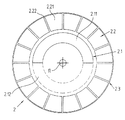
2 目盛版
2.1 目盛トラック
2.2 目盛トラック
1.1 受信ランドパターン
1.2 受信ランドパターン
1.6 励起ランドパターン
1.11 第1部分
1.21 第1部分
1.12 第2部分
1.22 第2部分
2.11 導電性目盛領域
2.21 導電性目盛領域
2.12 非導電性目盛領域
2.22 非導電性目盛領域
Claims (8)
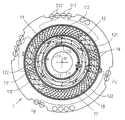
- プリント基板(1)及び目盛要素(2)から構成された電磁誘導式回転センサにあって、・プリント基板(1)を備え、1つの励起ランドパターン(1.6)及び少なくとも1つの受信ランドパターン(1.1,1.2)がこのプリント基板(1)上に形成されていて、かつ、この少なくとも1つの受信ランドパターン(1.1;1.2)は第1平面内に延在する第1部分(1.11;1.21)及び第2平面内に延在する第2部分(1.12;1.22)を有し、
・目盛要素(2)を備え、この目盛要素はプリント基板(1)に対して回転可能であり、かつ目盛トラック(2.1)を有し、この目盛トラック(2.1)は、交互に配置された導電性の目盛領域及び非導電性の目盛領域(2.11,2.12)から構成され、かつ、
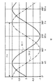
少なくとも1つの受信ランドパターン(1.1;1.2)は、目盛要素(2)に対する1回転内に奇数の信号周期を供給する電磁誘導式回転センサにおいて、
少なくとも1つの受信ランドパターン(1.1;1.2)の第1部分(1.11;1.21)は、第2部分(1.12;1.22)よりも大きい長さを有することを特徴とする電磁誘導式回転センサ。 - 受信ランドパターン(1.1;1.2)の第1部分(1.11;1.21)は、第2部分(1.12;1.22)の長さの少なくとも1.5 倍、又は、少なくとも3倍であることを特徴とする請求項1に記載の電磁誘導式回転センサ。
- 第1平面内に延在する第1部分(1.11;1.21)及び第2平面内に延在する第2部分(1.12;1.22)をそれぞれ有する多数の受信ランドパターン(1.1;1.2)が、プリント基板(1)上に形成されていて、かつ、より長い部分(1.11;1.21)がそれぞれ、1つの平面及び同一の平面内に延在することを特徴とする請求項1又は2に記載の電磁誘導式回転センサ。
- 少なくとも1つの受信ランドパターン(1.1;1.2)は、目盛要素(2)に対する1回転内で1つの信号周期を提供することを特徴とする請求項1〜3のいずれか1項に記載の電磁誘導式回転センサ。
- プリント基板(1)は、多層構造を有し、少なくとも1つの受信ランドパターン(1.1;1.2)の第1部分及び第2部分(1.11;1.21;1.12;1.22)が、非導電性の層(1.3)の異なる側面上に形成されていることを特徴とする請求項1〜4のいずれか1項に記載の電磁誘導式回転センサ。
- 受信ランドパターン(1.1;1.2)のより長い部分(1.11,1.21)は、受信ランドパターン(1.1;1.2)のより短い第2部分(1.12;1.22)が延在する平面よりも近い目盛要素(2)に配置されている平面内に延在することを特徴とする請求項1〜5のいずれか1項に記載の電磁誘導式回転センサ。
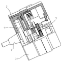
- プリント基板(1)及び目盛要素(2)から構成された電磁誘導式回転センサを有するシャフトエンコーダにあって、
・プリント基板(1)を備え、1つの励起ランドパターン(1.6)及び少なくとも1つの受信ランドパターン(1.1,1.2)がこのプリント基板(1)上に形成されていて、かつ、この少なくとも1つの受信ランドパターン(1.1;1.2)は第1平面内に延在する第1部分(1.11;1.21)及び第2平面内に延在する第2部分(1.12;1.22)を有し、
・目盛要素(2)を備え、この目盛要素はプリント基板(1)に対して回転可能であり、かつ目盛トラック(2.1)を有し、この目盛トラック(2.1)は、交互に配置された導電性の目盛領域及び非導電性の目盛領域(2.11,2.12)から構成され、かつ、少なくとも1つの受信ランドパターン(1.1;1.2)は、目盛要素(2)に対する1回転内に奇数の信号周期を供給する電磁誘導式回転センサを有するシャフトエンコーダにおいて、
少なくとも1つの受信ランドパターン(1.1;1.2)の第1部分(1.11;1.21)は、第2部分(1.12;1.22)よりも大きい長さを有することを特徴とするシャフトエンコーダ。 - 受信ランドパターン(1.1;1.2)のより長い部分(1.11,1.21)が、受信ランドパターン(1.1;1.2)のより短い第2部分(1.12;1.22)が延在する平面よりも近い目盛要素(2)に配置されている平面内に延在することを特徴とする請求項7に記載の電磁誘導式回転センサを有するシャフトエンコーダ。
Applications Claiming Priority (1)
| Application Number | Priority Date | Filing Date | Title |
|---|---|---|---|
| DE10320990A DE10320990A1 (de) | 2003-05-09 | 2003-05-09 | Induktiver Drehwinkelsensor und damit ausgestatteter Drehgeber |
Publications (3)
| Publication Number | Publication Date |
|---|---|
| JP2004333478A JP2004333478A (ja) | 2004-11-25 |
| JP2004333478A5 JP2004333478A5 (ja) | 2006-12-28 |
| JP4504064B2 true JP4504064B2 (ja) | 2010-07-14 |
Family
ID=32981320
Family Applications (1)
| Application Number | Title | Priority Date | Filing Date |
|---|---|---|---|
| JP2004102517A Expired - Fee Related JP4504064B2 (ja) | 2003-05-09 | 2004-03-31 | 電磁誘導式回転センサ及びこの電磁誘導式回転センサを備えたシャフトエンコーダ |
Country Status (6)
| Country | Link |
|---|---|
| US (1) | US7190158B2 (ja) |
| EP (1) | EP1475604B1 (ja) |
| JP (1) | JP4504064B2 (ja) |
| CN (1) | CN1311220C (ja) |
| AT (1) | ATE350645T1 (ja) |
| DE (2) | DE10320990A1 (ja) |
Families Citing this family (29)
| Publication number | Priority date | Publication date | Assignee | Title |
|---|---|---|---|---|
| ATE511744T1 (de) * | 2003-10-15 | 2011-06-15 | Chimei Innolux Corp | Elektronisches bauelement und verfahren zu dessen herstellung |
| CN100420914C (zh) * | 2005-04-19 | 2008-09-24 | 三丰株式会社 | 绝对式旋转编码器和千分尺 |
| DE102007007764A1 (de) * | 2007-02-16 | 2008-08-21 | Dr. Johannes Heidenhain Gmbh | Drehgeber und Verfahren zu dessen Betrieb |
| US7579829B1 (en) * | 2008-07-06 | 2009-08-25 | Avago Technologies Ecbu Ip (Singapore) Pte. Ltd. | Inductive multi-turn encoder |
| DE102008046741A1 (de) * | 2008-09-11 | 2010-03-18 | Dr. Johannes Heidenhain Gmbh | Induktiver Positionssensor, damit ausgestattetes Messsystem und Verfahren zum Betrieb eines Positionssensors |
| JP5133199B2 (ja) * | 2008-10-28 | 2013-01-30 | 株式会社ミツトヨ | 誘導検出型ロータリーエンコーダ |
| JP5069209B2 (ja) * | 2008-12-11 | 2012-11-07 | 東京コスモス電機株式会社 | 回転角度センサ |
| JP5239025B2 (ja) | 2009-03-11 | 2013-07-17 | 株式会社ミツトヨ | 誘導検出型ロータリエンコーダ |
| SE533913C2 (sv) | 2009-07-09 | 2011-03-01 | Leine & Linde Ab | Förfarande för drift av ett pulsgivaresystem samt ett pulsgivaresystem |
| JP2011211980A (ja) * | 2010-03-31 | 2011-10-27 | Hitachi Koki Co Ltd | 芝刈機 |
| US8742715B2 (en) | 2011-06-09 | 2014-06-03 | Simmonds Precision Products, Inc. | System and method for providing control of an electric motor using inductive rotary sensor |
| JP6087588B2 (ja) * | 2012-11-12 | 2017-03-01 | 三菱重工工作機械株式会社 | 変位センサの配線構造 |
| CN107429984B (zh) * | 2014-10-08 | 2020-03-03 | 糖果屋研发有限公司 | 旋转角度传感器、线性位移传感器、门装机构、及电刷 |
| GB201420842D0 (en) * | 2014-11-22 | 2015-01-07 | Howard Mark A And Kreit Darran | Detector |
| JP6480809B2 (ja) | 2015-05-21 | 2019-03-13 | オークマ株式会社 | 多回転検出器 |
| DE102016202867B3 (de) * | 2016-02-24 | 2017-04-06 | Robert Bosch Gmbh | Drehwinkelsensor |
| US20170307411A1 (en) * | 2016-04-22 | 2017-10-26 | KSR IP Holdings, LLC | Position sensor |
| DE102016217254B4 (de) * | 2016-09-09 | 2022-02-17 | Robert Bosch Gmbh | Drehwinkelsensor, Statorelement sowie Rotorelement für diesen |
| EP3355032B1 (de) * | 2017-01-30 | 2019-03-27 | Dr. Johannes Heidenhain GmbH | Sensor zur positionsmessung |
| JP7084640B2 (ja) | 2017-12-22 | 2022-06-15 | 株式会社松尾製作所 | 回転角度センサ |
| CN108871181B (zh) * | 2018-05-07 | 2020-11-10 | 哈尔滨理工大学 | 一种多对极磁电编码器动态多窗口区间预测角度细分方法 |
| CN109631958B (zh) * | 2018-11-28 | 2021-03-02 | 赛卓电子科技(上海)有限公司 | 位置编码器 |
| CN110406461A (zh) * | 2019-07-26 | 2019-11-05 | 浙江智动汽车部件有限公司 | 顶棚照明装置及其控制方法 |
| CN110470322A (zh) * | 2019-08-06 | 2019-11-19 | 上海交通大学 | 一种涡流式绝对编码器及其工作方法 |
| CN110470323A (zh) * | 2019-08-06 | 2019-11-19 | 上海交通大学 | 一种涡流式增量编码器及其工作方法 |
| JP7270903B2 (ja) * | 2019-10-02 | 2023-05-11 | 多摩川精機株式会社 | 平板型エンコーダ |
| DE102021121052A1 (de) | 2021-08-12 | 2023-02-16 | Josef Siraky | Sekundärspulenanordnung für ein induktives Encodersystem sowie induktives Encodersystem |
| CN114838655B (zh) * | 2022-04-12 | 2023-04-07 | 北京科技大学 | 一种多周期双极型电磁感应式角度传感器 |
| EP4273507A1 (de) * | 2022-05-05 | 2023-11-08 | Dr. Johannes Heidenhain GmbH | Abtastelement und induktive positionsmesseinrichtung mit diesem abtastelement |
Citations (2)
| Publication number | Priority date | Publication date | Assignee | Title |
|---|---|---|---|---|
| JPH10213407A (ja) * | 1996-11-29 | 1998-08-11 | Dr Johannes Heidenhain Gmbh | 位置測定装置の走査部材 |
| JPH10318781A (ja) * | 1997-04-16 | 1998-12-04 | Mitsutoyo Corp | 誘導型位置検出装置 |
Family Cites Families (10)
| Publication number | Priority date | Publication date | Assignee | Title |
|---|---|---|---|---|
| DE4127209C2 (de) * | 1991-08-16 | 1996-05-23 | Mehnert Walter Dr | Geber zur induktiven Erzeugung eines Meßsignals |
| DE59304986D1 (de) * | 1993-04-10 | 1997-02-13 | Heidenhain Gmbh Dr Johannes | Magnetisches Messsystem |
| DE4319322C2 (de) * | 1993-06-11 | 1998-04-23 | Heidenhain Gmbh Dr Johannes | Positionsmeßeinrichtung |
| EP0743508A2 (en) * | 1995-05-16 | 1996-11-20 | Mitutoyo Corporation | Induced current position transducer |
| US6788221B1 (en) * | 1996-06-28 | 2004-09-07 | Synaptics (Uk) Limited | Signal processing apparatus and method |
| US5841274A (en) * | 1997-01-29 | 1998-11-24 | Mitutoyo Corporation | Induced current absolute position transducer using a code-track-type scale and read head |
| GB9721891D0 (en) * | 1997-10-15 | 1997-12-17 | Scient Generics Ltd | Symmetrically connected spiral transducer |
| GB9811151D0 (en) * | 1998-05-22 | 1998-07-22 | Scient Generics Ltd | Rotary encoder |
| US6157188A (en) * | 1998-08-31 | 2000-12-05 | Mitutoyo Corporation | Compact, long-range absolute position transducer with an extensible compact encoding |
| DE10158223B4 (de) * | 2001-11-16 | 2017-10-05 | Dr. Johannes Heidenhain Gmbh | Drehwinkel-Messgerät |
-
2003
- 2003-05-09 DE DE10320990A patent/DE10320990A1/de not_active Withdrawn
-
2004
- 2004-01-31 EP EP04002112A patent/EP1475604B1/de not_active Expired - Lifetime
- 2004-01-31 AT AT04002112T patent/ATE350645T1/de not_active IP Right Cessation
- 2004-01-31 DE DE502004002496T patent/DE502004002496D1/de not_active Expired - Lifetime
- 2004-03-31 JP JP2004102517A patent/JP4504064B2/ja not_active Expired - Fee Related
- 2004-05-07 US US10/841,304 patent/US7190158B2/en active Active
- 2004-05-09 CN CNB2004100433803A patent/CN1311220C/zh not_active Expired - Fee Related
Patent Citations (2)
| Publication number | Priority date | Publication date | Assignee | Title |
|---|---|---|---|---|
| JPH10213407A (ja) * | 1996-11-29 | 1998-08-11 | Dr Johannes Heidenhain Gmbh | 位置測定装置の走査部材 |
| JPH10318781A (ja) * | 1997-04-16 | 1998-12-04 | Mitsutoyo Corp | 誘導型位置検出装置 |
Also Published As
| Publication number | Publication date |
|---|---|
| DE10320990A1 (de) | 2004-11-25 |
| CN1311220C (zh) | 2007-04-18 |
| US20040222787A1 (en) | 2004-11-11 |
| EP1475604B1 (de) | 2007-01-03 |
| EP1475604A2 (de) | 2004-11-10 |
| JP2004333478A (ja) | 2004-11-25 |
| DE502004002496D1 (de) | 2007-02-15 |
| CN1550750A (zh) | 2004-12-01 |
| EP1475604A3 (de) | 2006-01-18 |
| ATE350645T1 (de) | 2007-01-15 |
| US7190158B2 (en) | 2007-03-13 |
Similar Documents
| Publication | Publication Date | Title |
|---|---|---|
| JP4504064B2 (ja) | 電磁誘導式回転センサ及びこの電磁誘導式回転センサを備えたシャフトエンコーダ | |
| US9383184B2 (en) | Inductive position-measuring device | |
| US6111402A (en) | Position measuring instrument having a scanning element with multiple scanning tracks | |
| CN109883305B (zh) | 感应的位置测量装置 | |
| JP5360720B2 (ja) | 位置エンコーダおよび機械の可動部の位置を検出する方法 | |
| JP5314125B2 (ja) | 誘導式回転角センサおよび誘導式回転角センサを作動させる方法 | |
| CN110220538B (zh) | 多匝转动编码器 | |
| JP6558923B2 (ja) | 誘導式角度測定装置のための走査部材 | |
| JP2022091109A (ja) | 走査素子とこの走査素子を備えた誘導式位置測定装置 | |
| US11585678B2 (en) | Scanning element and inductive position measuring device having a scanning element | |
| JP2022037885A (ja) | 走査素子と、走査素子を備えた誘導式位置測定装置 | |
| KR101065220B1 (ko) | 모터 | |
| US11841248B2 (en) | Scanning element and inductive position measuring device having a scanning element | |
| JP2023122545A (ja) | 走査素子およびこの走査素子を備えた誘導式位置測定装置 | |
| CN116026231A (zh) | 感应式角度测量装置 | |
| US11578962B2 (en) | Inductive position measuring device | |
| CN112805537A (zh) | 用于传感器-发送器系统的传感器单元以及具有这种传感器单元的传感器-发送器系统 | |
| JP2023165624A (ja) | 走査要素およびこの走査要素を備えた誘導式位置測定機構 | |
| US20240077337A1 (en) | Scanning element and inductive position measuring device with this scanning element |
Legal Events
| Date | Code | Title | Description |
|---|---|---|---|
| A521 | Request for written amendment filed |
Free format text: JAPANESE INTERMEDIATE CODE: A523 Effective date: 20061114 |
|
| A621 | Written request for application examination |
Free format text: JAPANESE INTERMEDIATE CODE: A621 Effective date: 20061114 |
|
| A131 | Notification of reasons for refusal |
Free format text: JAPANESE INTERMEDIATE CODE: A131 Effective date: 20090728 |
|
| A601 | Written request for extension of time |
Free format text: JAPANESE INTERMEDIATE CODE: A601 Effective date: 20091027 |
|
| A602 | Written permission of extension of time |
Free format text: JAPANESE INTERMEDIATE CODE: A602 Effective date: 20091030 |
|
| A521 | Request for written amendment filed |
Free format text: JAPANESE INTERMEDIATE CODE: A523 Effective date: 20100118 |
|
| TRDD | Decision of grant or rejection written | ||
| A01 | Written decision to grant a patent or to grant a registration (utility model) |
Free format text: JAPANESE INTERMEDIATE CODE: A01 Effective date: 20100323 |
|
| A01 | Written decision to grant a patent or to grant a registration (utility model) |
Free format text: JAPANESE INTERMEDIATE CODE: A01 |
|
| A61 | First payment of annual fees (during grant procedure) |
Free format text: JAPANESE INTERMEDIATE CODE: A61 Effective date: 20100422 |
|
| R150 | Certificate of patent or registration of utility model |
Ref document number: 4504064 Country of ref document: JP Free format text: JAPANESE INTERMEDIATE CODE: R150 Free format text: JAPANESE INTERMEDIATE CODE: R150 |
|
| FPAY | Renewal fee payment (event date is renewal date of database) |
Free format text: PAYMENT UNTIL: 20130430 Year of fee payment: 3 |
|
| FPAY | Renewal fee payment (event date is renewal date of database) |
Free format text: PAYMENT UNTIL: 20140430 Year of fee payment: 4 |
|
| R250 | Receipt of annual fees |
Free format text: JAPANESE INTERMEDIATE CODE: R250 |
|
| R250 | Receipt of annual fees |
Free format text: JAPANESE INTERMEDIATE CODE: R250 |
|
| R250 | Receipt of annual fees |
Free format text: JAPANESE INTERMEDIATE CODE: R250 |
|
| R250 | Receipt of annual fees |
Free format text: JAPANESE INTERMEDIATE CODE: R250 |
|
| R250 | Receipt of annual fees |
Free format text: JAPANESE INTERMEDIATE CODE: R250 |
|
| R250 | Receipt of annual fees |
Free format text: JAPANESE INTERMEDIATE CODE: R250 |
|
| R250 | Receipt of annual fees |
Free format text: JAPANESE INTERMEDIATE CODE: R250 |
|
| LAPS | Cancellation because of no payment of annual fees |