JP4490686B2 - Record carrier and apparatus for scanning the record carrier - Google Patents
Record carrier and apparatus for scanning the record carrier Download PDFInfo
- Publication number
- JP4490686B2 JP4490686B2 JP2003511236A JP2003511236A JP4490686B2 JP 4490686 B2 JP4490686 B2 JP 4490686B2 JP 2003511236 A JP2003511236 A JP 2003511236A JP 2003511236 A JP2003511236 A JP 2003511236A JP 4490686 B2 JP4490686 B2 JP 4490686B2
- Authority
- JP
- Japan
- Prior art keywords
- deformation
- frequency
- modulated
- record carrier
- information
- Prior art date
- Legal status (The legal status is an assumption and is not a legal conclusion. Google has not performed a legal analysis and makes no representation as to the accuracy of the status listed.)
- Expired - Lifetime
Links
Images


Classifications
-
- G—PHYSICS
- G11—INFORMATION STORAGE
- G11B—INFORMATION STORAGE BASED ON RELATIVE MOVEMENT BETWEEN RECORD CARRIER AND TRANSDUCER
- G11B7/00—Recording or reproducing by optical means, e.g. recording using a thermal beam of optical radiation by modifying optical properties or the physical structure, reproducing using an optical beam at lower power by sensing optical properties; Record carriers therefor
- G11B7/007—Arrangement of the information on the record carrier, e.g. form of tracks, actual track shape, e.g. wobbled, or cross-section, e.g. v-shaped; Sequential information structures, e.g. sectoring or header formats within a track
-
- G—PHYSICS
- G11—INFORMATION STORAGE
- G11B—INFORMATION STORAGE BASED ON RELATIVE MOVEMENT BETWEEN RECORD CARRIER AND TRANSDUCER
- G11B20/00—Signal processing not specific to the method of recording or reproducing; Circuits therefor
- G11B20/10—Digital recording or reproducing
- G11B20/10009—Improvement or modification of read or write signals
- G11B20/10481—Improvement or modification of read or write signals optimisation methods
-
- G—PHYSICS
- G11—INFORMATION STORAGE
- G11B—INFORMATION STORAGE BASED ON RELATIVE MOVEMENT BETWEEN RECORD CARRIER AND TRANSDUCER
- G11B27/00—Editing; Indexing; Addressing; Timing or synchronising; Monitoring; Measuring tape travel
- G11B27/10—Indexing; Addressing; Timing or synchronising; Measuring tape travel
- G11B27/19—Indexing; Addressing; Timing or synchronising; Measuring tape travel by using information detectable on the record carrier
- G11B27/24—Indexing; Addressing; Timing or synchronising; Measuring tape travel by using information detectable on the record carrier by sensing features on the record carrier other than the transducing track ; sensing signals or marks recorded by another method than the main recording
-
- G—PHYSICS
- G11—INFORMATION STORAGE
- G11B—INFORMATION STORAGE BASED ON RELATIVE MOVEMENT BETWEEN RECORD CARRIER AND TRANSDUCER
- G11B27/00—Editing; Indexing; Addressing; Timing or synchronising; Monitoring; Measuring tape travel
- G11B27/10—Indexing; Addressing; Timing or synchronising; Measuring tape travel
- G11B27/19—Indexing; Addressing; Timing or synchronising; Measuring tape travel by using information detectable on the record carrier
- G11B27/28—Indexing; Addressing; Timing or synchronising; Measuring tape travel by using information detectable on the record carrier by using information signals recorded by the same method as the main recording
- G11B27/30—Indexing; Addressing; Timing or synchronising; Measuring tape travel by using information detectable on the record carrier by using information signals recorded by the same method as the main recording on the same track as the main recording
- G11B27/3027—Indexing; Addressing; Timing or synchronising; Measuring tape travel by using information detectable on the record carrier by using information signals recorded by the same method as the main recording on the same track as the main recording used signal is digitally coded
-
- G—PHYSICS
- G11—INFORMATION STORAGE
- G11B—INFORMATION STORAGE BASED ON RELATIVE MOVEMENT BETWEEN RECORD CARRIER AND TRANSDUCER
- G11B7/00—Recording or reproducing by optical means, e.g. recording using a thermal beam of optical radiation by modifying optical properties or the physical structure, reproducing using an optical beam at lower power by sensing optical properties; Record carriers therefor
- G11B7/007—Arrangement of the information on the record carrier, e.g. form of tracks, actual track shape, e.g. wobbled, or cross-section, e.g. v-shaped; Sequential information structures, e.g. sectoring or header formats within a track
- G11B7/00745—Sectoring or header formats within a track
-
- G—PHYSICS
- G11—INFORMATION STORAGE
- G11B—INFORMATION STORAGE BASED ON RELATIVE MOVEMENT BETWEEN RECORD CARRIER AND TRANSDUCER
- G11B7/00—Recording or reproducing by optical means, e.g. recording using a thermal beam of optical radiation by modifying optical properties or the physical structure, reproducing using an optical beam at lower power by sensing optical properties; Record carriers therefor
- G11B7/24—Record carriers characterised by shape, structure or physical properties, or by the selection of the material
- G11B7/2407—Tracks or pits; Shape, structure or physical properties thereof
- G11B7/24073—Tracks
- G11B7/24082—Meandering
-
- G—PHYSICS
- G11—INFORMATION STORAGE
- G11B—INFORMATION STORAGE BASED ON RELATIVE MOVEMENT BETWEEN RECORD CARRIER AND TRANSDUCER
- G11B2220/00—Record carriers by type
- G11B2220/20—Disc-shaped record carriers
- G11B2220/21—Disc-shaped record carriers characterised in that the disc is of read-only, rewritable, or recordable type
- G11B2220/215—Recordable discs
- G11B2220/216—Rewritable discs
-
- G—PHYSICS
- G11—INFORMATION STORAGE
- G11B—INFORMATION STORAGE BASED ON RELATIVE MOVEMENT BETWEEN RECORD CARRIER AND TRANSDUCER
- G11B2220/00—Record carriers by type
- G11B2220/20—Disc-shaped record carriers
- G11B2220/21—Disc-shaped record carriers characterised in that the disc is of read-only, rewritable, or recordable type
- G11B2220/215—Recordable discs
- G11B2220/218—Write-once discs
-
- G—PHYSICS
- G11—INFORMATION STORAGE
- G11B—INFORMATION STORAGE BASED ON RELATIVE MOVEMENT BETWEEN RECORD CARRIER AND TRANSDUCER
- G11B2220/00—Record carriers by type
- G11B2220/20—Disc-shaped record carriers
- G11B2220/25—Disc-shaped record carriers characterised in that the disc is based on a specific recording technology
- G11B2220/2525—Magneto-optical [MO] discs
-
- G—PHYSICS
- G11—INFORMATION STORAGE
- G11B—INFORMATION STORAGE BASED ON RELATIVE MOVEMENT BETWEEN RECORD CARRIER AND TRANSDUCER
- G11B2220/00—Record carriers by type
- G11B2220/20—Disc-shaped record carriers
- G11B2220/25—Disc-shaped record carriers characterised in that the disc is based on a specific recording technology
- G11B2220/2537—Optical discs
- G11B2220/2545—CDs
-
- G—PHYSICS
- G11—INFORMATION STORAGE
- G11B—INFORMATION STORAGE BASED ON RELATIVE MOVEMENT BETWEEN RECORD CARRIER AND TRANSDUCER
- G11B7/00—Recording or reproducing by optical means, e.g. recording using a thermal beam of optical radiation by modifying optical properties or the physical structure, reproducing using an optical beam at lower power by sensing optical properties; Record carriers therefor
Description
本発明は、情報ブロックの記録を企図した情報トラック、を表示するサーボ・トラックを備えている記録キャリア、に関するものであって、サーボ・トラックは、記録キャリア情報を符号化するよう変調された、物理的パラメータの変形を所定の周波数に備え、サーボ・トラックは、前記変形の周波数及び/又は位相が所定の周波数から偏移する、変調された部分、及び前記の周期的変形だけを含んでいる変調されていない部分を備えるものである。 The present invention relates to a record carrier comprising a servo track displaying an information track intended for recording an information block, the servo track being modulated to encode record carrier information, Provide a modification of the physical parameter at a predetermined frequency, and the servo track contains only a modulated portion, and the periodic deformation of the deformation, the frequency and / or phase of the deformation deviates from the predetermined frequency It comprises an unmodulated part.
本発明はさらに、前記情報トラックを表示しているサーボ・トラックを備える記録キャリア上の情報トラックの情報ブロックを記録し、及び/又は読み取る手段を備えている記録及び/又はプレイバックの機器に関するものであって、当該機器は、前記サーボ・トラックを走査する手段、及び所定の周波数における、前記サーボ・トラックの物理的パラメータの変形から記録キャリア情報を回復する復調手段を備え、前記サーボ・トラックは、前記変形の周波数及び/又は位相が前記の所定の周波数から偏移する、変調された部分、及び前記周期的変形だけを含んでいる変調されていない部分を備えるものである。 The invention further relates to a recording and / or playback device comprising means for recording and / or reading an information block of an information track on a record carrier comprising a servo track displaying said information track The apparatus comprises means for scanning the servo track, and demodulation means for recovering record carrier information from a deformation of a physical parameter of the servo track at a predetermined frequency, the servo track being , Comprising a modulated part in which the frequency and / or phase of the deformation deviates from the predetermined frequency and an unmodulated part containing only the periodic deformation.
本発明はさらに、前記記録キャリアを製造する方法に関するものである。 The invention further relates to a method for producing the record carrier.
従来の技術には、記録キャリア、及び、情報を読み取る及び/又は記録する機器に関するものがある(例えば、特許文献1参照。)。当該文献によれば、前記情報はアドレス・コードを含む情報信号に符号化され、及びアドレス・コードによって情報ブロックに細区分される。前記記録キャリアは、サーボ・トラックを備え、これは一般にプリグルーブ(あらかじめ、溝があるもの)と呼ばれ、前記トラックを走査する際にサーボ信号を発生させる。前記プリグルーブの物理的パラメータ、例えば半径方向の位置、は周期的に変動し、いわゆるウォブルを発生させている。当該ウォブルは、前記トラックの走査中に、前記サーボ信号の変形を引き起こし、及びウォブル信号を発生させ得る。前記ウォブルは位置情報を符号化するよう、位相変調を用いて変調される。一般に、ディジタル位置情報を符号化するのに用いる、前記位相変調はディジタル位相変調(PSK)と呼ばれる。記録中に、前記位置情報は前記ウォブル信号から回復され、前記情報ブロックにおける前記アドレス・コードと前記位置情報との間の所定の関係を保つことによって前記情報ブロックの位置を定めるよう利用される。 Conventional techniques include a record carrier and a device that reads and / or records information (see, for example, Patent Document 1). According to this document, the information is encoded into an information signal including an address code, and is subdivided into information blocks according to the address code. The record carrier is provided with servo tracks, which are generally called pregrooves ( previously grooved) and generate servo signals when scanning the tracks. The physical parameters of the pregroove, for example, the position in the radial direction, are periodically changed to generate a so-called wobble. The wobble can cause deformation of the servo signal and generate a wobble signal during scanning of the track. The wobble is modulated using phase modulation to encode position information. Generally, the phase modulation used to encode digital position information is called digital phase modulation (PSK). During recording, the position information is recovered from the wobble signal and used to determine the position of the information block by maintaining a predetermined relationship between the address code and the position information in the information block.
また、位置情報が設けられた、再記録可能なコンパクト・ディスク(CD)システムに関するものもある(例えば、特許文献2参照。)。 There are also related to a re-recordable compact disc (CD) system provided with position information (see, for example, Patent Document 2).
前記の公知の1つのシステムの問題点は、前記ウォブル信号が、前記の(トラッキング・)サーボ・システムによって使用される周波数範囲内となる低周波成分を含むことにある。それゆえに、前記サーボ・システムは前記ウォブル信号の変調によって妨害される。さらに、前記の変調されたウォブル信号は、前記情報信号の周波数範囲内となる高周波成分を含み、その結果、前記の回復された情報信号から前記情報を正確に検波するのを妨げることがある。 Problems of the known one system, the wobble signal is to include a low frequency component falls within the frequency range used by the above (tracking) servo system. Therefore, the servo system is disturbed by the modulation of the wobble signal. Further, the modulated wobble signal of the includes a high frequency component falls within the frequency range of the information signal, the result of that, it may interfere with the said recovered information signal for accurately detecting the information .
本発明の目的は、例えば、前記ウォブル信号による前記の妨害を弱める、記録キャリア及び機器を提供することである。 An object of the present invention is to provide a record carrier and a device that, for example, weaken the disturbance caused by the wobble signal.
本発明によれば、前記の記録キャリアは、前記の変調された部分と変調されていない部分との間のトランジション(遷移)部分での前記変形の勾配が実質的に連続していることを特徴とする。さらに、前記の記録及び/又はプレイバックの機器は、前記復調手段が、前記変形の勾配が実質的に連続している、前記の変調された部分と変調されていない部分との間のトランジションで開始して、変調された部分を検波する検波手段を備えることを特徴とする。本発明は、以下に説明された認識によるものである。多くの光学式記録書式は、とりわけ、記録クロック発生のために、一般にウォブルと呼ばれる、前記サーボ・トラックの周期的変形、を備え、前記ウォブルは通常、主に変化がなく、記録クロック・ジッタを減少させる。変調された部分では、周波数が変更され、又は位相ジャンプが用いられ、及び、前記ウォブルの振幅がゼロの時に、変調されていない部分と変調された部分との間のトランジションが現れる。本発明者は、当該のトランジションでのウォブルの勾配の切れ目が原因でさらに加わった、低周波及び高周波成分が、結果として発生されるウォブル信号によってもたらされることがわかった。振幅がゼロではないが、トランジション前の前記の変調されていない信号及びトランジション後の前記の変調された信号、の勾配が実質的に等しい前記ウォブル中の一部分、に前記トランジションをずらすことによって、前記の妨害周波数成分は薄められる。 According to the present invention, the gradient of the deformation of the record carrier is substantially continuous at a transition portion between the modulated portion and the unmodulated portion. And Further, the recording and / or playback device may be configured such that the demodulating means is in a transition between the modulated portion and the unmodulated portion, wherein the deformation gradient is substantially continuous. It is characterized by comprising detection means for starting and detecting the modulated part. The present invention is based on the recognition described below. Many optical recording formats comprise, among other things, a periodic deformation of the servo track, commonly referred to as wobble, for recording clock generation, the wobble usually being largely unchanged and recording clock jitter. Decrease. In the modulated part, the frequency is changed or a phase jump is used, and when the wobble amplitude is zero, a transition between the unmodulated part and the modulated part appears. The inventor has found that the resulting wobble signal results in additional low and high frequency components due to wobble slope breaks in the transition. By shifting the transition to a portion in the wobble whose amplitude is not zero but the gradient of the unmodulated signal before the transition and the modulated signal after the transition is substantially equal, The interference frequency component of is reduced.
前記記録キャリアの他の実施態様は、前記変形が実質的に正弦波であり、及びトランジションが前記正弦波の最小値及び/又は最高値に位置することを特徴とするものである。この利点は、正弦波のピーク値、すなわち最小値及び最大値で前記信号の勾配がゼロであることにある。それゆえに、信号の勾配が連続している状態で、周波数の変動を適用し得る。 Another embodiment of the record carrier is characterized in that the deformation is substantially sinusoidal and the transition is located at the minimum and / or maximum value of the sinusoid. The advantage is that the slope of the signal is zero at the peak value of the sine wave, ie the minimum and maximum values. Therefore, with the slope of the signal is continuous may apply variations in frequency.
本発明による、前記方法、機器及び記録キャリアの、望ましい実施態様は、別のクレームに記載する。 According to the invention, the method, devices and record carrier, preferred embodiment, you according to another claim.
本発明はウォブルの変調を用いて説明されているが、例えばトラック幅のような、トラックの、他のふさわしいどんなパラメータも、変調されることがある。さらに記録キャリアについては光ディスクが説明されているが、磁気ディスク又はテープのような、他の媒体も用いることがある。本明細書及び特許請求の範囲の原文では、「comprising」の語は、記載された構成要素と手段は列挙されているもの以外の他の要素又はステップの存在を排除せず、及び構成要素のすぐ前にある「a」又は「an」の語は当該構成要素が複数存在することを排除せず、どんな参照記号も本特許請求の範囲を限定せず、本発明はハードウェアとソフトウェアの両方によって実装されることがあり、及びいくつかの「means」は同一のハードウェア品目によって形成されることがあるものである。さらに、本発明の範囲は本明細書及び本特許請求の範囲に記載の実施態様に限定されず、及び本発明は、上記にて説明された新規性を持った、特徴又は特徴の組み合わせ、全てに見出されるものである。 Although the present invention has been described using wobble modulation, any other suitable parameter of the track, such as track width, may be modulated. Further, although an optical disk is described for the record carrier, other media such as a magnetic disk or tape may be used. In the present specification and claims, the word “comprising” does not exclude the presence of other elements or steps than those listed, and the elements and steps listed, and The word “a” or “an” immediately preceding does not exclude the presence of a plurality of such components, any reference sign does not limit the scope of the claims, and the invention includes both hardware and software. And several “means” may be formed by the same hardware item. Further, the scope of the present invention is not limited to the embodiments described in this specification and the claims, and the present invention includes all the features or combinations of features having the novelty described above. Is found.
本発明は、図面を参照し、以下に説明するものである。 The present invention will be described below with reference to the drawings.
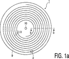
図1aは記録するために用いられることが予定されているトラック9が設けられた円板形の記録キャリア1、及び中心穴10を示すものである。前記トラック9は巻き線3のらせん状のパターンに配置される。図1bは記録キャリアのb−b線で切断した断面であり、透明な基板5が記録レイヤ6及び保護レイヤ7とともに設けられる。前記記録レイヤ6は、例えば相変化によって、光学的に記録可能である、又は、周知の再読み取り可能なCD若しくは再記録可能なCDのような、情報記録機器によって、磁気光学的に記録可能である。前記記録レイヤは又、生産工程を通じて情報が設けられることがあり、その場合、最初に親ディスクが製造され、後に、プレスによって増加される。前記情報は情報ブロックに編成され、及び、例えば、CDにおける異なった長さのピットの連続、のような、多量の放射と少量の放射を反映している区域が連続する形態の、光学的に読み取り可能なマークによって表される。一実施態様では、再記録可能型の前記記録キャリアの前記トラック9は前記の、記録されていない、記録キャリアの製造中に設けられるサーボパターンによって示される。前記サーボパターンは、例えば走査中に記録ヘッドが前記トラック9をたどることを可能にするプリグルーブ4によって、形成される。当該プリグルーブ4は、より深く、若しくは高くした部分、又は、周囲から逸脱している特定の物質特性、で実装されることがある。あるいは、前記サーボパターンは、巻き線毎にランドからグルーブへのトランジション、又はその逆が起こっていることを伴う、ランド及びグルーブ・パターンと呼ばれる、巻き線の高くした部分とより深い部分が交互に並ぶ交替列が備えられることがある。図1c及びdはウォブルと呼ばれる、前記プリグルーブの物理的パラメータの周期的変形の2つの例を示すものである。図1cは水平方向の位置の変形を表すものであって、及び図1dは幅方向の変形を表すものである。前記ウォブルはトラッキング・サーボセンサにてウォブル信号を発生させる。前記ウォブルは、例えば、周波数変調されて、アドレス、タイム・コード、又は巻き線情報のような位置情報が、その変調に符号化される。サーボパターンはさらに、例えば、周期的にトラッキング信号を発生させる、規則正しく分布されたサブパターン、を備えることもある。
FIG. 1a shows a disc-
前記サーボ・トラックの前記変形は、いわゆる、変調されていない部分と呼ばれる、変化のないウォブルの比較的大きな部分を備える。さらに、前記サーボ・トラックは、変調された部分と呼ばれる、前記ウォブルの周波数及び/又は位相が、所定のウォブル周波数から偏移する、比較的短い部分を備える。 The deformation of the servo track comprises a relatively large part of the wobble without change, called the so-called unmodulated part. Furthermore, the servo track comprises a relatively short part, called the modulated part, where the frequency and / or phase of the wobble deviates from a predetermined wobble frequency.
図2aはMSK−sinの変調を例示するものである。当該図は前記ウォブルの変調された部分の変形を示すものである。最小位相推移変調(MSK)の正弦波タイプ(MSK−sin)ではデータ値0は、前記ウォブルがゼロ交差から開始する、ウォブルの全周期21又は反転された周期22によって表される。データ値1は1.5倍高い周波数で表され、その結果ウォブル23は正から開始していて、又ウォブル24は負から開始している。それゆえ、MSK変調は1.0×ウォブル周波数(fwob)の周波数の正弦波及び1.5×fwobの周波数の正弦波に準拠する。MSK−sinでは、周波数は前記ウォブル信号のゼロ交差で変動する。周波数が変動する部分では、勾配はとぎれている。
FIG. 2a illustrates the modulation of MSK-sin. The figure shows a modification of the modulated part of the wobble. Sine type (MSK-sin) the data value of the minimum phase shift modulation (MSK) 0, the wobble starts from the zero crossing is represented by the
図2bはMSK−cos変調を例示するものである。当該図は前記ウォブルの変調された部分の変形を示すものである。MSKの余弦波タイプ(MSK−cos)では、データ値0は、前記ウォブルの振幅の最大値又は最小値から開始する、ウォブルの全周期25又は反転された周期26、によって表される。データ値1は1.5倍高い周波数によって表され、その結果、ウォブル27は正の値から開始していて、又ウォブル28は負の値から開始していて、その上、最大値又は最小値から開始している。それゆえ、MSK変調は、1.0×fwobの周波数の正弦波及び1.5×fwobの周波数の正弦波、に準拠している。MSK−cosでは、周波数は前記ウォブル信号の最大値又は最小値で変動する。周波数が変動する部分では勾配は連続している。MSK−cosの全ての波形は、1ウォブルの長さの周波数周期で積分すると、直流(DC)成分を含まないが、MSK−sinの1.5×fwobの波形はDC成分を含むことを特筆する。前記DC成分はMSK−sinの1.5×fwobの反転波形によって差し引きし得るが、MSK−cos変調で前記のようなDC成分を含まないことは、サーボ・システムに関連する低周波数範囲で、より少ない妨害周波数成分が含まれるということに帰結する。
FIG. 2b illustrates MSK-cos modulation. The figure shows a modification of the modulated part of the wobble. In a cosine-wave type MSK (MSK-cos), a
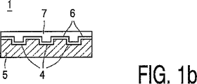
図3はMSK−sin及びMSK−cos信号を表すものである。当該図はMSK−sin(32)とMSK−cos(35)の変調された波形を単一データ・ビットについて例示したものである。真ん中の線(32,35)はMSK−sin(左)及びMSK−cos(右)のディスク上の波形を(実線で)表すものである。参考までに、単一トーンの正弦波又は余弦波信号も(点線で)表す。両方の例は3ウォブル周期の長さのデータ・ビットについてのものである。当該データ・ビットの、最初及び最後の部分は、図2aと2bを参照して、上記にて説明されている。前記3周期の真ん中の周期には、反転されたウォブルがある。上の線(31,34)は、MSK−sin(左)およびMSK−cos(右)波形と、変調されていない参照ウォブルとの間の違いを表すものである。下の線(33,36)は波形(32,35)と前記参照ウォブルとを掛け合わせた結果を表すものである。 FIG. 3 shows the MSK-sin and MSK-cos signals. The figure illustrates the MSK-sin (32) and MSK-cos (35) modulated waveforms for a single data bit. The middle line (32, 35) represents the waveform on the disk of MSK-sin (left) and MSK-cos (right) (solid line). For reference, a single tone sine or cosine wave signal is also represented (in dotted lines). Both examples are for data bits that are 3 wobble periods long. The first and last part of the data bit has been described above with reference to FIGS. 2a and 2b. In the middle of the three periods, there is an inverted wobble. Upper line (31, 34) is representative of the MSK-sin (left) and MSK-cos (right) wave, the difference between the reference wobble not modulated. The lower lines (33, 36) represent the result of multiplying the waveform (32, 35) and the reference wobble.
図4は1データ・ビットの電力スペクトル密度を表すものである。点線41はMSK−sinのスペクトルであって、実線42はMSK−cosのスペクトルである。MSK−cosのスペクトル42はMSK−sinのスペクトル41よりも狭い。すなわち、MSK−cosはより少ない妨害周波数成分を生じさせていて、MSK−sinよりも、検波器によって、より狭い範囲で濾波し得る。MSK−cosの検波性能は、濾波後に結果として生ずる信号対雑音比次第では、MSK−sinのものよりもよりすぐれたものになるであろう。
FIG. 4 represents the power spectral density of one data bit. The dotted
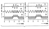
図5は記録キャリア1を走査する読み取り機器を表すものである。光ディスクの情報の記録と読み取り、及び、フォーマット化、誤り訂正とチャネル符号化の規則は、例えば前記CDシステムから、周知であるものである。図5の装置は、前記記録キャリア1を読み取るよう形成され、当該記録キャリアは図1にて表された記録キャリアと同一のものである。前記機器は、記録キャリアにおけるトラックを走査する読み取りヘッド52、及び、記録キャリア1を回転させる駆動装置55、例えばチャネル復号器と誤り訂正器とを備えている、読み取り回路53、トラッキング装置51、並びにシステム制御装置56、を備えている読み取り制御手段が設けられたものである。前記読み取りヘッドは、光学素子によって誘導された放射ビーム65によって、前記記録キャリアの前記記録レイヤのトラックに集束された放射スポット66を発生させる通常タイプの光学素子を備えたものである。放射ビーム65は、例えばレーザ・ダイオードのような、放射源によって発生されるものである。前記読み取りヘッドはさらに前記記録レイヤに、放射ビーム65を集束させるフォーカシング・アクチュエータ、及びスポット66をトラックの中心で半径方向に細かく位置を定めるトラッキング・アクチュエータ59、を備えている。前記装置は、トラック上で半径方向に読み取りヘッド52を粗く位置を定める位置決め装置54を備える。トラッキング・アクチュエータ59は、光学素子を半径方向に移動させるコイルを備えることがあり、又は、前記読み取りヘッドの可動部分、若しくは、固定位置に前記光システムの一部が実装される場合には固定位置の一部分にある、反射素子の角度を変化させるよう形成されることがあるものである。前記記録レイヤによって反射された放射は、読み取り信号、トラッキング・エラー及びフォーカシング・エラー信号を含めた、検出信号57、を発生させるための、例えば四分円ダイオードのような、通常タイプの検出器によって検出される。トラッキング装置51は、前記読み取りヘッドからの前記トラッキング・エラー信号を受信し、トラッキング・アクチュエータ59を制御するために、前記読み取りヘッドに結合されるものである。読み取り中に、読み取り信号は、矢印64にて示されたように、読み取り回路53にて出力情報に変換される。前記装置には、前記記録キャリアの前記サーボ・トラックを走査する際に検出器信号57からアドレス情報を検出および回復する、アドレス検出器50が設けられている。前記機器には、さらに、制御しているコンピュータ・システム又は利用者から命令を受信し、制御ライン58経由で、例えば、駆動装置55、位置決め装置54、アドレス検出器50、トラッキング装置51並びに読み取り回路53に接続されたシステム・バス経由で、前記装置を制御するシステム制御装置56が設けられる。当該の目的のために、前記システム制御装置は、下記に説明された手順を実行するよう、例えばマイクロプロセッサ、プログラム記憶装置及び制御ゲートのような、制御回路を備える。システム制御装置56は又、論理回路のステート・マシンとしても実装されることがある。前記読み取り機器は、例えば連続したウォブルのような、周期的変形を含んでいるトラックを備えているディスクを読み取るよう形成される。前記読み取り制御機器は、前記の周期的変形を検出し、それに応じて、前記トラックから所定量のデータを読み取るよう形成される。一実施態様によれば、読み取りクロックは前記周期的変形に同期化され、及び読み取り回路53は前記周期的変形のそれぞれの発生毎に、固定数のチャネル・ビットを読み取る。一実施態様によれば、前記読み取り制御手段は記録されていない区域の後に来る前記トラックの区域からデータを回復するよう形成される。読み取り回路53では、読み取りクロックは記録されていない区域での前記の周期的変形に同期化され、及び読み取りスピードは前記の記録されていない区域を走査している間に調節される。それゆえ、記録された区域の最初の部分では、読み取り回路53は前記の記録されたデータのスピードに固定される。特に、アドレス検出器50は、前記の変調されたウォブルから得られた、前記の変調された信号から、例えば位置情報や記録制御データのような、記録キャリア情報を読み取るよう形成される。アドレス検出器50には前記ウォブルの勾配が連続している、前記ウォブル信号の所定のトランジション部分、から始めて、変調されたウォブルを検波する検波装置がある。最大値(又は最小値部分)にトランジションを備えている正弦波のウォブルについては、検波を開始する部分は前記の最大値(又は最小値)である。望ましい実施態様は、アドレス検出器50が、前記ウォブル信号の周波数スペクトルに準拠した整合フィルタを備えるものである。当該整合フィルタは、前記ウォブル信号のほうが、ゼロ交差でトランジションを備えているウォブル信号よりも周波数スペクトルが狭いので、前記の変調されたウォブル信号の信号対雑音比を向上させる。前記アドレス検出器はさらに、記録キャリア情報のワードを回復する、ワード検出装置を備える。当該ワードの最初の部分は、前記の変調されていないウォブルの長いシーケンス、の後に来る同期化信号から検出される。データ・ビットの発生及び値は前記の変調されたウォブルに準拠して検出される。他の実施態様では、他の種類の、前記記録キャリアの前記の値の同期化又は復号化が適用されてもよい。
FIG. 5 shows a reading device for scanning the
図6は、例えば電磁放射のビーム65によって磁気光学式又は光学式方法にて(相変化、又は色素によって)(再)記録可能のタイプの、本発明による、記録キャリア上に情報を記録する機器を表すものである。前記機器は、さらに、読み取りし得るよう装備され、及び、図5を参照して上記にて説明された、前記読み取り装置と同一の構成要素、を含むものである。但し、記録/読み取りヘッド62を有する点、及び、例えばフォーマッタ(書式設定器)と誤り符号器とチャネル符号器とを備えた記録回路60を除いて、前記読み取り制御手段と同一の構成要素を含む記録制御手段を有する点は異なる。記録/読み取りヘッド62は、読み取りヘッド52と同一の機能を、記録機能と共に備え、及び、記録回路60に連結されるものである。(矢印63によって示された)記録回路60の入力に提示された情報は、フォーマット化及び符号化規則によって、論理セクタと物理セクタに分布され、及び記録/読み取りヘッド62の記録信号61に変換される。システム制御ユニット56は、記録回路60を制御し、及び、前記読み取り装置について上記に説明した、前記位置情報の回復並びに位置決め手順を実行するよう形成されるものである。前記の記録動作中には、情報を表しているマークが前記記録キャリアに形成される。前記記録制御手段は、例えば、位相ロック・ループを前記の周期性にロックすることによって、前記の周期的変形を検出するよう形成される。アドレス検出器50は図5を参照して上記に説明されたものである。
FIG. 6 shows an apparatus for recording information on a record carrier according to the invention, of the type that can be (re) recorded in a magneto-optical or optical manner (by phase change or dye), for example by a
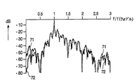
図7aと図7bはMSK−sin及びMSK−cosの電力スペクトル密度(PSD)を、周期的に繰り返された2つの異なったビット・パターンについて、表すものである。図7aは、あるビット・パターンについて、MSK−sinのPSD71、及び、MSK−cosのPSD72、を表すものである。図7bは他のビット・パターンについて、MSK−sinのPSD73、及び、MSK−cosのPSD74、を表すものである。これらは、スペクトルの中心部においてMSK−sin及びMSK−cosのPSDが実質的に、同様であるということがわかる。しかしながら、0.1×fwob周辺の低周波数ではMSK−cosのPSDはMSK−sinのPSDよりも10dB以上低い。これは、(例えば、1.5×fwobの周波数で)前記MSK−cos信号の一つのfwob周期セグメントにDC成分がないことと関係があり、そのようなMSK−sinの一つの周期セグメントは、次の(反転した)MSK−sinセグメントにおける信号で後に補償される、DC成分を含む。MSK−cosの低周波スペクトルは、したがって、MSK−sinの低周波スペクトルよりもかなり低く、それは、前記サーボの、より低いひずみを理由として、1つの利点となるものである。さらに、MSK−cosのよりなめらかな波形は、周波数が変動する部分で勾配がとぎれたMSK―sinと比較して、切れずに続いた勾配によってもたらされる。さらに2×fwobを超える高周波範囲では、MSK−cosのPSDはMSK−cosのPSDよりもやや低い。それゆえ、高周波範囲にも、より少ない妨害周波数成分が存在する。
Figures 7a and 7b represent the power spectral density (PSD) of MSK-sin and MSK-cos for two different bit patterns repeated periodically. FIG. 7a shows an MSK-
1 記録キャリア
4 サーボ・トラック
9 情報トラック
25 ウォブル
26 ウォブル
27 ウォブル
28 ウォブル
50 検波手段
1
Claims (8)
前記所定の周波数において前記変形のみを有する変調されていない部分と、
前記変形の周波数及び/又は位相が、前記変調されていない部分の前記所定の周波数及び/又は位相から偏移する変調された部分と
により、記録キャリア情報を符号化するために変調され、
前記変形の勾配が、前記変調された部分と前記変調されていない部分との間の偏移において実質的に連続しており、前記偏移は、前記正弦波の変形の最小値及び/又は最大値に位置することを特徴とする記録キャリア。A record carrier comprising a servo track indicating the position of an information track intended for recording an information block, the servo track comprising a substantially sinusoidal deformation of a physical parameter, the deformation comprising: is monotonic Te predetermined frequency odor, said servo track,
An unmodulated portion having only the deformation at the predetermined frequency;
The frequency and / or phase of the deformation is modulated to encode record carrier information with a modulated portion that deviates from the predetermined frequency and / or phase of the unmodulated portion;
The deformation gradient is substantially continuous in a shift between the modulated portion and the unmodulated portion, the shift being a minimum and / or maximum of the deformation of the sine wave. A record carrier characterized by being located at a value.
前記復調手段は、前記変形の勾配が実質的に連続している、前記変調された部分と前記変調されていない部分との間の偏移において開始している前記変調された部分を検波する検波手段を備え、前記偏移は、前記正弦波の変形の最小値及び/又は最大値に位置し、前記検波手段は、前記最小値及び/又は前記最大値の開始を検出するよう構成されることを特徴とする機器。A recording and / or playback device comprising means for storing and / or reading information blocks in an information track on a record carrier according to claim 1, wherein the device scans a servo track. means, at said predetermined frequency, from the signal generated by the pre-SL is a monotonic variation, and a demodulating means for recovering the modulated record carrier information,
The demodulating means detects the modulated part starting at the shift between the modulated part and the unmodulated part, wherein the gradient of the deformation is substantially continuous. And the deviation is located at a minimum and / or maximum value of the deformation of the sine wave, and the detection means is configured to detect the start of the minimum value and / or the maximum value. Equipment characterized by.
前記所定の周波数において前記変形のみを有する変調されていない部分、及び
前記変形の周波数及び位相が、前記変調されていない部分の前記所定の周波数及び/又は位相から偏移する変調された部分により、記録キャリア情報を符号化するために変調され、前記変調された部分と前記変調されていない部分との間の偏移は、実質的に連続するよう前記変形の勾配を保っており、前記偏移は、前記正弦波の変形の最小値及び/又は最大値に位置することを特徴とする、記録キャリアを製造する方法。2. The method of manufacturing a record carrier according to claim 1, wherein the record carrier is provided with a servo track indicating a position of an information track intended to record an information block, and the servo track is physically parameters substantially monotonic variations of the sine wave is provided at a predetermined frequency, said deformation,
An unmodulated portion having only the deformation at the predetermined frequency, and a modulated portion in which the frequency and phase of the deformation deviate from the predetermined frequency and / or phase of the unmodulated portion, The deviation between the modulated part and the non-modulated part modulated to encode record carrier information keeps the deformation gradient to be substantially continuous, the deviation Is located at the minimum and / or maximum value of the deformation of the sine wave.
Applications Claiming Priority (2)
| Application Number | Priority Date | Filing Date | Title |
|---|---|---|---|
| EP01202545 | 2001-07-02 | ||
| PCT/IB2002/002736 WO2003005350A1 (en) | 2001-07-02 | 2002-06-27 | Record carrier and apparatus for scanning the record carrier |
Related Child Applications (1)
| Application Number | Title | Priority Date | Filing Date |
|---|---|---|---|
| JP2009215539A Division JP4649528B2 (en) | 2001-07-02 | 2009-09-17 | Record carrier and apparatus for scanning the record carrier |
Publications (3)
| Publication Number | Publication Date |
|---|---|
| JP2004534346A JP2004534346A (en) | 2004-11-11 |
| JP2004534346A5 JP2004534346A5 (en) | 2009-11-12 |
| JP4490686B2 true JP4490686B2 (en) | 2010-06-30 |
Family
ID=8180582
Family Applications (2)
| Application Number | Title | Priority Date | Filing Date |
|---|---|---|---|
| JP2003511236A Expired - Lifetime JP4490686B2 (en) | 2001-07-02 | 2002-06-27 | Record carrier and apparatus for scanning the record carrier |
| JP2009215539A Expired - Fee Related JP4649528B2 (en) | 2001-07-02 | 2009-09-17 | Record carrier and apparatus for scanning the record carrier |
Family Applications After (1)
| Application Number | Title | Priority Date | Filing Date |
|---|---|---|---|
| JP2009215539A Expired - Fee Related JP4649528B2 (en) | 2001-07-02 | 2009-09-17 | Record carrier and apparatus for scanning the record carrier |
Country Status (26)
| Country | Link |
|---|---|
| US (3) | US7274627B2 (en) |
| EP (2) | EP1405306B1 (en) |
| JP (2) | JP4490686B2 (en) |
| KR (1) | KR100900733B1 (en) |
| CN (2) | CN101025989B (en) |
| AR (1) | AR034683A1 (en) |
| AT (2) | ATE441180T1 (en) |
| BR (1) | BRPI0205695B1 (en) |
| CO (1) | CO5550510A2 (en) |
| CY (2) | CY1109643T1 (en) |
| DE (2) | DE60237051D1 (en) |
| DK (2) | DK1926093T3 (en) |
| EA (1) | EA005639B1 (en) |
| EG (1) | EG23269A (en) |
| ES (2) | ES2331873T3 (en) |
| HK (1) | HK1064206A1 (en) |
| HR (1) | HRP20030143B1 (en) |
| IL (1) | IL159668A0 (en) |
| MA (1) | MA26205A1 (en) |
| MX (1) | MXPA03001745A (en) |
| MY (1) | MY149315A (en) |
| NO (1) | NO20030927L (en) |
| PT (2) | PT1926093E (en) |
| TN (1) | TNSN03009A1 (en) |
| TW (1) | TWI233607B (en) |
| WO (1) | WO2003005350A1 (en) |
Cited By (1)
| Publication number | Priority date | Publication date | Assignee | Title |
|---|---|---|---|---|
| JP2009295275A (en) * | 2001-07-02 | 2009-12-17 | Koninkl Philips Electronics Nv | Record carrier and apparatus for scanning record carrier |
Families Citing this family (21)
| Publication number | Priority date | Publication date | Assignee | Title |
|---|---|---|---|---|
| JP4652641B2 (en) * | 2001-10-11 | 2011-03-16 | ソニー株式会社 | Disc recording medium, disc drive apparatus, and playback method |
| JP3789423B2 (en) | 2001-11-17 | 2006-06-21 | エルジー電子株式会社 | Apparatus and method for encoding wobble signal recorded on optical disk, and apparatus and method for decoding wobble signal read from optical disk |
| TWI298156B (en) | 2002-10-24 | 2008-06-21 | Tian Holdings Llc | Discrimination method for light storage device |
| CN100377219C (en) * | 2003-03-31 | 2008-03-26 | 上海乐金广电电子有限公司 | Demodulation device/method of optical disk dither signal and demodulation device/method thereof |
| EP1489611A1 (en) | 2003-06-16 | 2004-12-22 | Deutsche Thomson-Brandt Gmbh | Wobble demodulation for high density optical recording media |
| EP1489612B1 (en) * | 2003-06-16 | 2017-05-03 | Thomson Licensing | Wobble demodulation for high density optical recording media |
| CN100412972C (en) | 2003-09-15 | 2008-08-20 | 宇田控股有限公司 | Method for ascertaining the format of an loaded optical disc |
| DE10345950A1 (en) | 2003-10-02 | 2005-05-19 | Pari GmbH Spezialisten für effektive Inhalation | Inhalation therapy device with valve |
| US20050226114A1 (en) | 2004-03-31 | 2005-10-13 | Stanley Liow | Method and apparatus for generating absolute time in pregroove data |
| JP4114605B2 (en) * | 2003-12-24 | 2008-07-09 | ソニー株式会社 | Information processing apparatus, information recording medium, information processing method, and computer program |
| US7570561B2 (en) | 2004-05-25 | 2009-08-04 | Bryan Tai | Method for determining type of digital versatile discs |
| WO2005117008A1 (en) * | 2004-05-25 | 2005-12-08 | Via Technologies, Inc. | Method and apparatus for type determination of digital versatile discs |
| US7626907B2 (en) | 2004-05-25 | 2009-12-01 | Ricky Chang | Method and apparatus for determining type of digital versatile disc |
| US7746745B2 (en) | 2004-05-25 | 2010-06-29 | Ricky Chang | Method for determining the type of digital versatile disc |
| US7161753B2 (en) * | 2005-01-28 | 2007-01-09 | Komag, Inc. | Modulation of sidewalls of servo sectors of a magnetic disk and the resultant disk |
| FR2898226B1 (en) * | 2006-03-06 | 2009-03-06 | Excem Soc Par Actions Simplifi | ELECTROLUMINESCENT TRANSMISSION DEVICE FOR OPTICAL TRANSMISSION IN FREE SPACE |
| FR2907272B1 (en) * | 2006-10-13 | 2008-12-26 | Commissariat Energie Atomique | METHOD FOR MANAGING THE END OF DISCHARGE OF A RECHARGEABLE BATTERY |
| TWI347596B (en) | 2007-01-11 | 2011-08-21 | Ind Tech Res Inst | Optical recording carrier, signal generating apparatus, information recording method, and information reading apparatus |
| JPWO2012063326A1 (en) * | 2010-11-09 | 2014-05-12 | 株式会社東芝 | Information recording medium, information reproducing apparatus, and information recording apparatus |
| US8582405B1 (en) * | 2012-09-25 | 2013-11-12 | Oracle International Corporation | Matched pattern signal decoding |
| KR20200086512A (en) * | 2019-01-09 | 2020-07-17 | 한국전자통신연구원 | Method and apparatus for backscatter communication in pattern-based demodulation |
Family Cites Families (24)
| Publication number | Priority date | Publication date | Assignee | Title |
|---|---|---|---|---|
| JPS57158057A (en) * | 1981-03-25 | 1982-09-29 | Sony Corp | Correcting method for wow and flutter |
| NL8800152A (en) | 1988-01-22 | 1989-08-16 | Philips Nv | OPTICAL READABLE RECORD CARRIER OF THE DESCRIBABLE TYPE, AN APPARATUS FOR MANUFACTURING SUCH RECORD CARRIER, AND ARRANGEMENTS FOR RECORDING AND / OR READING INFORMATION ON / FROM SUCH RECORD CARRIER. |
| NL8800151A (en) * | 1988-01-22 | 1989-08-16 | Philips Nv | METHOD AND APPARATUS FOR RECORDING AN INFORMATION SIGNAL |
| US5363360A (en) * | 1993-09-27 | 1994-11-08 | Eastman Kodak Company | Method and apparatus for detecting and processing synchronization marks extracted from a prerecorded wobbled groove on a compact disk |
| JPH1069646A (en) * | 1996-08-29 | 1998-03-10 | Ricoh Co Ltd | Optical disk medium, optical disk device |
| KR100580538B1 (en) * | 1996-11-18 | 2006-11-30 | 코닌클리케 필립스 일렉트로닉스 엔.브이. | Recording device, recording medium and method of recording multiple information blocks and reading device for reading multiple information blocks |
| JPH10208249A (en) | 1997-01-21 | 1998-08-07 | Sony Corp | Optical disk |
| CN1204120A (en) * | 1997-05-08 | 1999-01-06 | 索尼株式会社 | Frequency demodulating circuit, optical disk apparatus thereof and preforming device |
| US6310838B1 (en) * | 1997-09-03 | 2001-10-30 | U.S. Philips Corporation | Record carrier and apparatus for scanning the record carrier |
| JP3339436B2 (en) * | 1998-12-08 | 2002-10-28 | 住友金属工業株式会社 | Mold powder for continuous casting |
| ES2209823T3 (en) * | 1999-01-25 | 2004-07-01 | Koninklijke Philips Electronics N.V. | RECORDING SUPPORT AND APPLIANCE TO EXPLORE THE RECORDING SUPPORT. |
| JP4099914B2 (en) * | 1999-12-10 | 2008-06-11 | ソニー株式会社 | Optical disc and optical disc apparatus |
| JP2001338421A (en) | 2000-03-21 | 2001-12-07 | Sony Corp | Disk drive device and wobble information generating method |
| HU228528B1 (en) * | 2000-12-11 | 2013-03-28 | Koninkl Philips Electronics Nv | Record carrier of the optical type and a device for recording and/or playback for use with such a record carrier |
| JP2002237096A (en) * | 2001-02-09 | 2002-08-23 | Ricoh Co Ltd | Optical recording medium |
| JP5175413B2 (en) * | 2001-03-12 | 2013-04-03 | ソニー株式会社 | Disc recording medium, reproducing device, recording device |
| TWI229854B (en) * | 2001-03-16 | 2005-03-21 | Koninkl Philips Electronics Nv | Record carrier and apparatus for scanning the record carrier |
| KR100727916B1 (en) * | 2001-05-02 | 2007-06-13 | 삼성전자주식회사 | A optical disc |
| KR100408285B1 (en) * | 2001-05-24 | 2003-12-03 | 삼성전자주식회사 | Optical recording medium on which multi-modulated header signals are recorded, method and apparatus for recording the header signals, method and apparatus for reproducing the header signals |
| ES2331873T3 (en) | 2001-07-02 | 2010-01-19 | Koninklijke Philips Electronics N.V. | RECORDING SUPPORT AND APPLIANCE TO EXPLORE THE RECORDING SUPPORT. |
| CN101740052B (en) * | 2001-10-15 | 2012-09-05 | 皇家飞利浦电子股份有限公司 | Record carrier and apparatus for scanning the record carrier |
| JP4121264B2 (en) * | 2001-10-16 | 2008-07-23 | コーニンクレッカ フィリップス エレクトロニクス エヌ ヴィ | Disk drive device and wobble information detection method |
| JP3789423B2 (en) * | 2001-11-17 | 2006-06-21 | エルジー電子株式会社 | Apparatus and method for encoding wobble signal recorded on optical disk, and apparatus and method for decoding wobble signal read from optical disk |
| WO2004107344A1 (en) * | 2003-05-27 | 2004-12-09 | Koninklijke Philips Electronics N.V. | Bit synchronization detection means |
-
2002
- 2002-06-27 ES ES02743520T patent/ES2331873T3/en not_active Expired - Lifetime
- 2002-06-27 MX MXPA03001745A patent/MXPA03001745A/en active IP Right Grant
- 2002-06-27 PT PT08100910T patent/PT1926093E/en unknown
- 2002-06-27 EP EP02743520A patent/EP1405306B1/en not_active Expired - Lifetime
- 2002-06-27 TN TNPCT/IB2002/002736A patent/TNSN03009A1/en unknown
- 2002-06-27 US US10/481,143 patent/US7274627B2/en not_active Expired - Lifetime
- 2002-06-27 PT PT02743520T patent/PT1405306E/en unknown
- 2002-06-27 DE DE60237051T patent/DE60237051D1/en not_active Expired - Lifetime
- 2002-06-27 WO PCT/IB2002/002736 patent/WO2003005350A1/en active Application Filing
- 2002-06-27 DE DE60233498T patent/DE60233498D1/en not_active Expired - Lifetime
- 2002-06-27 KR KR1020037002917A patent/KR100900733B1/en active IP Right Grant
- 2002-06-27 ES ES08100910T patent/ES2348846T3/en not_active Expired - Lifetime
- 2002-06-27 DK DK08100910.2T patent/DK1926093T3/en active
- 2002-06-27 CN CN2007100063439A patent/CN101025989B/en not_active Expired - Fee Related
- 2002-06-27 JP JP2003511236A patent/JP4490686B2/en not_active Expired - Lifetime
- 2002-06-27 IL IL15966802A patent/IL159668A0/en not_active IP Right Cessation
- 2002-06-27 BR BRPI0205695-0A patent/BRPI0205695B1/en active IP Right Grant
- 2002-06-27 AT AT02743520T patent/ATE441180T1/en active
- 2002-06-27 EP EP08100910A patent/EP1926093B1/en not_active Expired - Lifetime
- 2002-06-27 EA EA200400133A patent/EA005639B1/en not_active IP Right Cessation
- 2002-06-27 CN CNB028132734A patent/CN100370525C/en not_active Expired - Lifetime
- 2002-06-27 DK DK02743520T patent/DK1405306T3/en active
- 2002-06-27 AT AT08100910T patent/ATE474314T1/en active
- 2002-07-01 EG EG2002070765A patent/EG23269A/en active
- 2002-07-01 MY MYPI20022483A patent/MY149315A/en unknown
- 2002-07-02 AR ARP020102486A patent/AR034683A1/en active IP Right Grant
- 2002-08-26 TW TW091119243A patent/TWI233607B/en not_active IP Right Cessation
-
2003
- 2003-02-27 NO NO20030927A patent/NO20030927L/en not_active Application Discontinuation
- 2003-02-27 HR HR20030143A patent/HRP20030143B1/en not_active IP Right Cessation
- 2003-11-28 CO CO03105190A patent/CO5550510A2/en not_active Application Discontinuation
-
2004
- 2004-01-02 MA MA27471A patent/MA26205A1/en unknown
- 2004-09-13 HK HK04106921.7A patent/HK1064206A1/en not_active IP Right Cessation
-
2007
- 2007-08-27 US US11/845,140 patent/US8644119B2/en active Active
-
2009
- 2009-09-17 JP JP2009215539A patent/JP4649528B2/en not_active Expired - Fee Related
- 2009-11-25 CY CY20091101217T patent/CY1109643T1/en unknown
-
2010
- 2010-10-06 CY CY20101100889T patent/CY1110818T1/en unknown
-
2013
- 2013-12-30 US US14/143,073 patent/US9449642B2/en not_active Expired - Fee Related
Cited By (2)
| Publication number | Priority date | Publication date | Assignee | Title |
|---|---|---|---|---|
| JP2009295275A (en) * | 2001-07-02 | 2009-12-17 | Koninkl Philips Electronics Nv | Record carrier and apparatus for scanning record carrier |
| JP4649528B2 (en) * | 2001-07-02 | 2011-03-09 | コーニンクレッカ フィリップス エレクトロニクス エヌ ヴィ | Record carrier and apparatus for scanning the record carrier |
Also Published As
Similar Documents
| Publication | Publication Date | Title |
|---|---|---|
| JP4649528B2 (en) | Record carrier and apparatus for scanning the record carrier | |
| JP4653315B2 (en) | Record carrier and apparatus for scanning the record carrier | |
| JP2004534346A5 (en) | ||
| BG63925B1 (en) | Record carrier, playback device and method of recording information | |
| USRE44088E1 (en) | Record carrier having a servo track with position information in accordance with a modulation type and permanent information in accordance with a different modulation type, and apparatus for scanning the record carrier | |
| JP2008165978A (en) | Record carrier and device scanning the record carrier | |
| AU2002339218A1 (en) | Record carrier and apparatus for scanning the record carrier | |
| US6952381B2 (en) | Record carrier including a servo track having first and second modulated parts representing a data type and a word sync type, respectively, and an apparatus for scanning the record carrier |
Legal Events
| Date | Code | Title | Description |
|---|---|---|---|
| A621 | Written request for application examination |
Free format text: JAPANESE INTERMEDIATE CODE: A621 Effective date: 20050623 |
|
| A977 | Report on retrieval |
Free format text: JAPANESE INTERMEDIATE CODE: A971007 Effective date: 20071226 |
|
| A131 | Notification of reasons for refusal |
Free format text: JAPANESE INTERMEDIATE CODE: A131 Effective date: 20080304 |
|
| A601 | Written request for extension of time |
Free format text: JAPANESE INTERMEDIATE CODE: A601 Effective date: 20080528 |
|
| A602 | Written permission of extension of time |
Free format text: JAPANESE INTERMEDIATE CODE: A602 Effective date: 20080604 |
|
| A521 | Request for written amendment filed |
Free format text: JAPANESE INTERMEDIATE CODE: A523 Effective date: 20080903 |
|
| A02 | Decision of refusal |
Free format text: JAPANESE INTERMEDIATE CODE: A02 Effective date: 20090519 |
|
| A524 | Written submission of copy of amendment under article 19 pct |
Free format text: JAPANESE INTERMEDIATE CODE: A524 Effective date: 20090917 |
|
| A911 | Transfer to examiner for re-examination before appeal (zenchi) |
Free format text: JAPANESE INTERMEDIATE CODE: A911 Effective date: 20090929 |
|
| A131 | Notification of reasons for refusal |
Free format text: JAPANESE INTERMEDIATE CODE: A131 Effective date: 20091124 |
|
| A521 | Request for written amendment filed |
Free format text: JAPANESE INTERMEDIATE CODE: A523 Effective date: 20100108 |
|
| A131 | Notification of reasons for refusal |
Free format text: JAPANESE INTERMEDIATE CODE: A131 Effective date: 20100202 |
|
| A521 | Request for written amendment filed |
Free format text: JAPANESE INTERMEDIATE CODE: A523 Effective date: 20100216 |
|
| TRDD | Decision of grant or rejection written | ||
| A01 | Written decision to grant a patent or to grant a registration (utility model) |
Free format text: JAPANESE INTERMEDIATE CODE: A01 Effective date: 20100309 |
|
| A01 | Written decision to grant a patent or to grant a registration (utility model) |
Free format text: JAPANESE INTERMEDIATE CODE: A01 |
|
| A61 | First payment of annual fees (during grant procedure) |
Free format text: JAPANESE INTERMEDIATE CODE: A61 Effective date: 20100402 |
|
| FPAY | Renewal fee payment (event date is renewal date of database) |
Free format text: PAYMENT UNTIL: 20130409 Year of fee payment: 3 |
|
| R150 | Certificate of patent or registration of utility model |
Ref document number: 4490686 Country of ref document: JP Free format text: JAPANESE INTERMEDIATE CODE: R150 Free format text: JAPANESE INTERMEDIATE CODE: R150 |
|
| FPAY | Renewal fee payment (event date is renewal date of database) |
Free format text: PAYMENT UNTIL: 20140409 Year of fee payment: 4 |
|
| R250 | Receipt of annual fees |
Free format text: JAPANESE INTERMEDIATE CODE: R250 |
|
| R250 | Receipt of annual fees |
Free format text: JAPANESE INTERMEDIATE CODE: R250 |
|
| R250 | Receipt of annual fees |
Free format text: JAPANESE INTERMEDIATE CODE: R250 |
|
| R250 | Receipt of annual fees |
Free format text: JAPANESE INTERMEDIATE CODE: R250 |
|
| R250 | Receipt of annual fees |
Free format text: JAPANESE INTERMEDIATE CODE: R250 |
|
| R250 | Receipt of annual fees |
Free format text: JAPANESE INTERMEDIATE CODE: R250 |
|
| R250 | Receipt of annual fees |
Free format text: JAPANESE INTERMEDIATE CODE: R250 |
|
| R250 | Receipt of annual fees |
Free format text: JAPANESE INTERMEDIATE CODE: R250 |
|
| R250 | Receipt of annual fees |
Free format text: JAPANESE INTERMEDIATE CODE: R250 |
|
| R250 | Receipt of annual fees |
Free format text: JAPANESE INTERMEDIATE CODE: R250 |
|
| EXPY | Cancellation because of completion of term |