EP1405306B1 - Record carrier and apparatus for scanning the record carrier - Google Patents
Record carrier and apparatus for scanning the record carrier Download PDFInfo
- Publication number
- EP1405306B1 EP1405306B1 EP02743520A EP02743520A EP1405306B1 EP 1405306 B1 EP1405306 B1 EP 1405306B1 EP 02743520 A EP02743520 A EP 02743520A EP 02743520 A EP02743520 A EP 02743520A EP 1405306 B1 EP1405306 B1 EP 1405306B1
- Authority
- EP
- European Patent Office
- Prior art keywords
- modulated
- variation
- frequency
- record carrier
- predetermined frequency
- Prior art date
- Legal status (The legal status is an assumption and is not a legal conclusion. Google has not performed a legal analysis and makes no representation as to the accuracy of the status listed.)
- Expired - Lifetime
Links
Images


Classifications
-
- G—PHYSICS
- G11—INFORMATION STORAGE
- G11B—INFORMATION STORAGE BASED ON RELATIVE MOVEMENT BETWEEN RECORD CARRIER AND TRANSDUCER
- G11B7/00—Recording or reproducing by optical means, e.g. recording using a thermal beam of optical radiation by modifying optical properties or the physical structure, reproducing using an optical beam at lower power by sensing optical properties; Record carriers therefor
- G11B7/007—Arrangement of the information on the record carrier, e.g. form of tracks, actual track shape, e.g. wobbled, or cross-section, e.g. v-shaped; Sequential information structures, e.g. sectoring or header formats within a track
-
- G—PHYSICS
- G11—INFORMATION STORAGE
- G11B—INFORMATION STORAGE BASED ON RELATIVE MOVEMENT BETWEEN RECORD CARRIER AND TRANSDUCER
- G11B20/00—Signal processing not specific to the method of recording or reproducing; Circuits therefor
- G11B20/10—Digital recording or reproducing
- G11B20/10009—Improvement or modification of read or write signals
- G11B20/10481—Improvement or modification of read or write signals optimisation methods
-
- G—PHYSICS
- G11—INFORMATION STORAGE
- G11B—INFORMATION STORAGE BASED ON RELATIVE MOVEMENT BETWEEN RECORD CARRIER AND TRANSDUCER
- G11B27/00—Editing; Indexing; Addressing; Timing or synchronising; Monitoring; Measuring tape travel
- G11B27/10—Indexing; Addressing; Timing or synchronising; Measuring tape travel
- G11B27/19—Indexing; Addressing; Timing or synchronising; Measuring tape travel by using information detectable on the record carrier
- G11B27/24—Indexing; Addressing; Timing or synchronising; Measuring tape travel by using information detectable on the record carrier by sensing features on the record carrier other than the transducing track ; sensing signals or marks recorded by another method than the main recording
-
- G—PHYSICS
- G11—INFORMATION STORAGE
- G11B—INFORMATION STORAGE BASED ON RELATIVE MOVEMENT BETWEEN RECORD CARRIER AND TRANSDUCER
- G11B27/00—Editing; Indexing; Addressing; Timing or synchronising; Monitoring; Measuring tape travel
- G11B27/10—Indexing; Addressing; Timing or synchronising; Measuring tape travel
- G11B27/19—Indexing; Addressing; Timing or synchronising; Measuring tape travel by using information detectable on the record carrier
- G11B27/28—Indexing; Addressing; Timing or synchronising; Measuring tape travel by using information detectable on the record carrier by using information signals recorded by the same method as the main recording
- G11B27/30—Indexing; Addressing; Timing or synchronising; Measuring tape travel by using information detectable on the record carrier by using information signals recorded by the same method as the main recording on the same track as the main recording
- G11B27/3027—Indexing; Addressing; Timing or synchronising; Measuring tape travel by using information detectable on the record carrier by using information signals recorded by the same method as the main recording on the same track as the main recording used signal is digitally coded
-
- G—PHYSICS
- G11—INFORMATION STORAGE
- G11B—INFORMATION STORAGE BASED ON RELATIVE MOVEMENT BETWEEN RECORD CARRIER AND TRANSDUCER
- G11B7/00—Recording or reproducing by optical means, e.g. recording using a thermal beam of optical radiation by modifying optical properties or the physical structure, reproducing using an optical beam at lower power by sensing optical properties; Record carriers therefor
- G11B7/007—Arrangement of the information on the record carrier, e.g. form of tracks, actual track shape, e.g. wobbled, or cross-section, e.g. v-shaped; Sequential information structures, e.g. sectoring or header formats within a track
- G11B7/00745—Sectoring or header formats within a track
-
- G—PHYSICS
- G11—INFORMATION STORAGE
- G11B—INFORMATION STORAGE BASED ON RELATIVE MOVEMENT BETWEEN RECORD CARRIER AND TRANSDUCER
- G11B7/00—Recording or reproducing by optical means, e.g. recording using a thermal beam of optical radiation by modifying optical properties or the physical structure, reproducing using an optical beam at lower power by sensing optical properties; Record carriers therefor
- G11B7/24—Record carriers characterised by shape, structure or physical properties, or by the selection of the material
- G11B7/2407—Tracks or pits; Shape, structure or physical properties thereof
- G11B7/24073—Tracks
- G11B7/24082—Meandering
-
- G—PHYSICS
- G11—INFORMATION STORAGE
- G11B—INFORMATION STORAGE BASED ON RELATIVE MOVEMENT BETWEEN RECORD CARRIER AND TRANSDUCER
- G11B2220/00—Record carriers by type
- G11B2220/20—Disc-shaped record carriers
- G11B2220/21—Disc-shaped record carriers characterised in that the disc is of read-only, rewritable, or recordable type
- G11B2220/215—Recordable discs
- G11B2220/216—Rewritable discs
-
- G—PHYSICS
- G11—INFORMATION STORAGE
- G11B—INFORMATION STORAGE BASED ON RELATIVE MOVEMENT BETWEEN RECORD CARRIER AND TRANSDUCER
- G11B2220/00—Record carriers by type
- G11B2220/20—Disc-shaped record carriers
- G11B2220/21—Disc-shaped record carriers characterised in that the disc is of read-only, rewritable, or recordable type
- G11B2220/215—Recordable discs
- G11B2220/218—Write-once discs
-
- G—PHYSICS
- G11—INFORMATION STORAGE
- G11B—INFORMATION STORAGE BASED ON RELATIVE MOVEMENT BETWEEN RECORD CARRIER AND TRANSDUCER
- G11B2220/00—Record carriers by type
- G11B2220/20—Disc-shaped record carriers
- G11B2220/25—Disc-shaped record carriers characterised in that the disc is based on a specific recording technology
- G11B2220/2525—Magneto-optical [MO] discs
-
- G—PHYSICS
- G11—INFORMATION STORAGE
- G11B—INFORMATION STORAGE BASED ON RELATIVE MOVEMENT BETWEEN RECORD CARRIER AND TRANSDUCER
- G11B2220/00—Record carriers by type
- G11B2220/20—Disc-shaped record carriers
- G11B2220/25—Disc-shaped record carriers characterised in that the disc is based on a specific recording technology
- G11B2220/2537—Optical discs
- G11B2220/2545—CDs
-
- G—PHYSICS
- G11—INFORMATION STORAGE
- G11B—INFORMATION STORAGE BASED ON RELATIVE MOVEMENT BETWEEN RECORD CARRIER AND TRANSDUCER
- G11B7/00—Recording or reproducing by optical means, e.g. recording using a thermal beam of optical radiation by modifying optical properties or the physical structure, reproducing using an optical beam at lower power by sensing optical properties; Record carriers therefor
Definitions
- the invention relates to a record carrier comprising a servo track indicating an information track intended for recording information blocks, which servo track has a variation of a physical parameter at a predetermined frequency which variation is modulated for encoding record carrier information, and which servo track has modulated parts in which the frequency and/or phase of the variation deviates from the predetermined frequency, and non-modulated parts having only said periodic variation.
- the invention further relates to recording and/or playback device comprising means for writing and/or reading information blocks in an information track on a record carrier that comprises a servo track indicating the information track, which device comprises means for scanning the servo track and demodulation means for retrieving record carrier information from a variation of a physical parameter of the servo track at a predetermined frequency, which servo track has modulated parts in which the frequency and/or phase of the variation deviates from the predetermined frequency, and non-modulated parts having only said periodic variation.
- the invention further relates to a method for manufacturing the record carrier.
- a record carrier and device for reading and/or writing information are known from WO 00/43996 (PHN 17323).
- the information is encoded into an information signal which includes address codes and is subdivided in accordance with the address codes into information blocks.
- the record carrier has a servo track, usually called pregroove, for causing servo signals to be generated when scanning the track.
- a physical parameter, e.g. the radial position, of the pregroove periodically varies constituting a so-called wobble. During the scanning of the track, this wobble leads to a variation of the servo signals and a wobble signal can be generated.
- the wobble is modulated using phase modulation for encoding position information.
- phase modulation used for encoding digital position information is called Phase Shift Keying (PSK).
- PSK Phase Shift Keying
- the position information is retrieved from the wobble signal and is used for positioning the information blocks by keeping a predefined relation between the address codes in the information blocks and the position information.
- the wobble signal comprises low frequency components in the frequency range which is used by the tracking servo system. Hence the servo system is disturbed by the wobble modulation. Further the modulated wobble signal may comprise high frequency components in the frequency range of the information signal, and therefore disturb the correct detection of the information from the retrieved information signal.
- JP 10-208249 describes modulation of a servo track for address information by frequency modulation.
- a data bit value 0 is represented by 3 wobble periods
- a data bit value 1 is represented by 4 wobble periods.
- the amplitude of the wobble is adapted proportional to the frequency to achieve a continuous slope at the zero crossing where the '0' and '1' parts join.
- a record carrier as defined in claim 1, a device as defined in claim 6 and a method as defined in claim 12.
- the invention is based on the following recognition.
- Many optical recording formats contain a periodic variation of the servo track, usually called wobble, inter alia for write-clock generation, which wobble is usually predominantly monotonic to reduce write-clock jitter.
- modulated parts the frequency is changed or even phase jumps are used, and the transitions between not modulated and modulated parts occur when the amplitude of the wobble is zero.
- the inventors have seen that due to the discontinuities in the slope of the wobble of such transitions additional low and high frequency components are generated in the resulting wobble signal. By shifting the transitions to a point in the wobble where the amplitude is not zero but where the slope of the non modulated signal before and the modulated signal after the transition are substantially equal such disturbing frequency components are reduced.
- a further embodiment of the record carrier is characterized in that the variation is substantially sinusoidal and the transitions are located at the minima and/or maxima of said sinus.
- the advantage is that at the peak values of a sinus, i.e. the minima and maxima, the slope of the signal is zero. Hence a change in frequency can be applied while the slope of the signal is continuous.
- Fig. 1a shows a disc-shaped record carrier 1 provided with a track 9 intended for recording and a central hole 10.
- the track 9 is arranged in accordance with a spiral pattern of windings 3.
- Fig. 1b is a cross-section taken on the line b-b of the record carrier 1, in which a transparent substrate 5 is provided with a recording layer 6 and a protective layer 7.
- the recording layer 6 may be optically writable, for example via phase change, or magnetooptically writable by a device for writing information such as the known CD-Rewritable or CD-Recordable.
- the recording layer may also be provided with information via a production process, in which first a master disc is made which is subsequently multiplied through pressing.
- the information is organized in information blocks and is represented by optically readable marks in the form of a succession of areas reflecting much radiation and little radiation such as, for example a succession of pits of different lengths in a CD.
- the track 9 on the record carrier of a rewritable type is indicated by a servopattern which is provided during manufacture of the blank record carrier.
- the servopattern is formed, for example by a pregroove 4 which enables a write head to follow the track 9 during scanning.
- the pregroove 4 may be implemented as a deeper or a raised part, or as a material property deviating from its ambience.
- the servopattern may consist of an alternation of elevated and deeper windings, referred to as land and groove patterns, with a transition from land to groove or vice versa taking place per winding.
- Figs. 1c and 1d show two examples of a periodical variation of a physical parameter of the pregroove, called wobble.
- Fig. 1c shows variation of the lateral position
- Fig. 1d shows variation of the width.
- This wobble produces a wobble signal in a tracking servosensor.
- the wobble is, for example, frequency- modulated, and position information such as an address, a time code or winding information is coded in the modulation.
- a description of a rewritable CD system which is provided with position information in such a way can be found in US 4,901,300 (PHN 12.398).
- a servopattern may also consist of, for example, regularly distributed sub-patterns which periodically cause tracking signals.
- the variation of the servo track includes relatively large parts of monotone wobble, so called non modulated parts. Further the servo track has relatively short parts where the frequency and/or phase of the wobble deviates from the predetermined wobble frequency, called modulated parts.
- Figure 2a shows the modulation of MSK-sin.
- the figure shows the variations in a modulated part of the wobble.
- a data value 0 is represented by a full period of the wobble 21 or an inverted period 22, starting at the zero crossing of the wobble.
- the data value 1 is represented by a frequency which is 1.5 times higher, so a positive starting wobble 23 or a negative starting wobble 24.
- the MSK modulation is based on sine waves with frequency 1.0 times the wobble frequency (fwob) and sine waves with frequency 1.5*fwob.
- the frequency changes at the zero crossings of the wobble signal. At the points where the frequency changes the slope is discontinuous.
- Figure 2b shows the modulation of MSK-cos.
- the figure shows the variations in a modulated part of the wobble.
- a data value 0 is represented by a full period of the wobble 25 or an inverted period 26, starting at the maximum or minimum amplitude of the wobble.
- the data value 1 is represented by a frequency which is 1.5 times higher, so a positive starting wobble 27 or a negative starting wobble 28, also starting at the maximum or minimum.
- the MSK modulation is based on sine waves with frequency 1.0*fwob and sine waves with frequency 1.5*fwob. With MSK-cos the frequency changes at the maxima or minima of the wobble signal.
- the slope is continuous. It is to be noted that all waveforms of the MSK-cos are without a DC component when integrated on the length of one wobble frequency period, whereas the 1.5 * fwob waveform of MSK-sin has a DC component.
- the DC component may be balanced by an inverted 1.5 * fwob MSK-sin waveform, but the absence of such DC components in the MSK-cos modulation results in less disturbing frequency components in the low frequency range relevant to servo systems.
- FIG. 3 shows MSK-sin and MSK-cos signals.
- the figure shows examples of the modulated wave forms for MSK-sin (32) and MSK-cos (35) for a single data bit.
- the central traces (32,35) show the wave form on the disc (solid lines) for MSK-sin (left) and MSK-cos (right).
- the single-tone sine or cosine signals are also shown (dotted lines). Both examples are for data bit with a length of 3 wobble periods. The first and last parts of such a data bit are described above with reference to Figure 2a and 2b . In the middle period of said 3 periods an inverted wobble is present.
- the top traces (31,34) show the difference between the MSK-sin (left) and MSK-cos (right) wave forms and a reference not modulated wobble.
- the bottom traces (33,36) show the result of multiplying the wave forms (32,35) with the reference wobble.
- Figure 4 shows the power spectral density of a data bit.
- the solid line 41 is the spectrum for MSK-sin
- the dashed line 42 is the spectrum for MSK-cos.
- the spectrum 42 of MSK-cos is narrower than the spectrum 41 of MSK-sin. In other words, MSK-cos is producing less disturbing frequency components and can be filtered more narrowly by the detector than MSK-sin. The detection performance of MSK-cos will be better compared to MSK-sin, depending on the resulting signal to noise ratio after filtering.
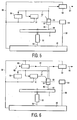
- Figures 5 shows a reading device for scanning a record carrier 1. Writing and reading of information on optical discs and formatting, error correcting and channel coding rules, are well-known in the art, e.g. from the CD system.
- the apparatus of Figure 5 is arranged for reading the record carrier 1, which record carrier is identical to the record carriers shown in Figure 1 .
- the device is provided with a read head 52 for scanning the track on the record carrier and read control means comprising drive unit 55 for rotating the record carrier 1, a read circuit 53 for example comprising a channel decoder and an error corrector, tracking unit 51 and a system control unit 56.
- the read head comprises optical elements of the usual type for generating a radiation spot 66 focused on a track of the recording layer of the record carrier via a radiation beam 65 guided through optical elements.
- the radiation beam 65 is generated by a radiation source, e.g. a laser diode.
- the read head further comprises a focusing actuator for focusing the radiation beam 65 on the recording layer and a tracking actuator 59 for fine positioning of the spot 66 in radial direction on the center of the track.
- the apparatus has a positioning unit 54 for coarsely positioning the read head 52 in the radial direction on the track.
- the tracking actuator 59 may comprise coils for radially moving an optical element or may be arranged for changing the angle of a reflecting element on a movable part of the read head or on a part on a fixed position in the case part of the optical system is mounted on a fixed position.
- the radiation reflected by the recording layer is detected by a detector of a usual type, e.g.
- the tracking unit 51 is coupled to the read head for receiving the tracking error signal from the read head and controlling the tracking actuator 59. During reading, the read signal is converted into output information, indicated by arrow 64, in the read circuit 53.
- the apparatus is provided with an address detector 50 for detecting and the retrieving address information from the detector signals 57 when scanning the servo track of the record carrier.
- the device is further provided with a system control unit 56 for receiving commands from a controlling computer system or from a user and for controlling the apparatus via control lines 58, e.g.
- the system control unit comprises control circuitry, for example a microprocessor, a program memory and control gates, for performing the procedures described below.
- the system control unit 56 may also be implemented as a state machine in logic circuits.
- the read device is arranged for reading a disc having tracks having a periodic variation, e.g. a continuous wobble.
- the read control unit are arranged for detecting the periodic variations and for reading in dependence thereon a predetermined amount data from the track.
- the read clock is synchronized to the periodic variations and the read circuit 53 reads a fixed number of channel bits for each instance of the periodic variations.
- the read control means are arranged for retrieving the data from an area of the track following an unrecorded area.
- the read clock is synchronized to the periodic variations in the unrecorded area and the reading speed is adjusted during scanning the unrecorded area. Hence at the start of the recorded area the read circuit 53 is locked in to the speed of the recorded data.
- the address detector 50 is arranged for reading record carrier information, e.g. position information and recording control data, from the modulated signal derived from the modulated wobble.
- the address detector 50 has a detection unit for detecting modulated wobbles starting at a predefined transition point in the wobble signal, at which transition point the slope of the wobble is continuous.
- the detecting starting point is at said maxima (or minima).
- the address detector 50 includes a matched filter based on the frequency spectrum of the wobble signal.
- the matched filter improves the signal to noise ratio of the modulated wobble signal, because the frequency spectrum of the wobble signal is narrower than the spectrum of a wobble signal having transitions at the zero crossing.
- the address detector further has a word detection unit for retrieving the words of record carrier information. The beginning of such a word is detected from a synchronization signal after a long sequence of non modulated wobbles. The occurrence and value of a data bit is detected based on the modulated wobbles. In further embodiments other types of synchronization or decoding of the values of the record carrier information may be applied.
- Figure 6 shows a device for writing information on a record carrier according to the invention of a type which is (re)writable in, for example a magneto-optical or optical manner (via phase change or dye) by means of a beam 65 of electromagnetic radiation.
- the device is also equipped for reading and comprises the same elements as the apparatus for reading described above with Figure 5 , except that it has a write/read head 62 and recording control means which comprise the same elements as the read control means, except for a write circuit 60 that comprises for example a formatter, an error encoder and a channel encoder.
- the write/read head 62 has the same function as the read head 52 together with a write function and is coupled to the write circuit 60.
- the information presented to the input of the write circuit 60 (indicated by the arrow 63) is distributed over logical and physical sectors according to formatting and encoding rules and converted into a write signal 61 for the write/read head 62.
- the system control unit 56 is arranged for controlling the write circuit 60 and for performing the position information recovery and positioning procedure as described above for the reading apparatus.
- marks representing the information are formed on the record carrier.
- the recording control means are arranged for detecting the periodic variations, for example by locking a phase locked loop to the periodicity thereof.
- the address detector 50 is described above with reference to Figure 5 .
- Figures 7a and 7b show the power spectral densities (PSDs) for MSK-sin and MSK-cos for two different bit patterns that are repeated periodically.
- Figure 7a shows for a certain bit pattern the PSD 71 for MSK-sin and the PSD 72 for MSK-cos.
- Figure 7b shows for another bit pattern the PSD 73 for MSK-sin and the PSD 74 for MSK-cos. It shows that the PSDs for MSK-sin and MSK-cos are substantially the same in the central parts of the spectrum. However, at low frequencies around 0.1*fwob the PSD of MSK-cos is more than 10 dB lower than the PSD of MSK-sin.
- any other suitable parameter of the track may be modulated, e.g. the track width.
- an optical disc has been described, but other media, such as a magnetic disc or tape, may be used. It is noted, that in this document the word 'comprising' does not exclude the presence of other elements or steps than those listed and the word 'a' or 'an' preceding an element does not exclude the presence of a plurality of such elements, that any reference signs do not limit the scope of the claims, that the invention may be implemented by means of both hardware and software, and that several 'means' may be represented by the same item of hardware.
Description
- The invention relates to a record carrier comprising a servo track indicating an information track intended for recording information blocks, which servo track has a variation of a physical parameter at a predetermined frequency which variation is modulated for encoding record carrier information, and which servo track has modulated parts in which the frequency and/or phase of the variation deviates from the predetermined frequency, and non-modulated parts having only said periodic variation.
- The invention further relates to recording and/or playback device comprising means for writing and/or reading information blocks in an information track on a record carrier that comprises a servo track indicating the information track, which device comprises means for scanning the servo track and demodulation means for retrieving record carrier information from a variation of a physical parameter of the servo track at a predetermined frequency, which servo track has modulated parts in which the frequency and/or phase of the variation deviates from the predetermined frequency, and non-modulated parts having only said periodic variation.
- The invention further relates to a method for manufacturing the record carrier.
- A record carrier and device for reading and/or writing information are known from
WO 00/43996 - A problem of the known system is that the wobble signal comprises low frequency components in the frequency range which is used by the tracking servo system. Hence the servo system is disturbed by the wobble modulation. Further the modulated wobble signal may comprise high frequency components in the frequency range of the information signal, and therefore disturb the correct detection of the information from the retrieved information signal.
-
JP 10-208249 data bit value 0 is represented by 3 wobble periods, whereas adata bit value 1 is represented by 4 wobble periods. The amplitude of the wobble is adapted proportional to the frequency to achieve a continuous slope at the zero crossing where the '0' and '1' parts join. - It is an object of the invention, for example, to provide a record carrier and device in which the above disturbance due to the wobble signal is reduced.
- According to the invention there is provided a record carrier as defined in
claim 1, a device as defined inclaim 6 and a method as defined in claim 12. The invention is based on the following recognition. Many optical recording formats contain a periodic variation of the servo track, usually called wobble, inter alia for write-clock generation, which wobble is usually predominantly monotonic to reduce write-clock jitter. In modulated parts the frequency is changed or even phase jumps are used, and the transitions between not modulated and modulated parts occur when the amplitude of the wobble is zero. The inventors have seen that due to the discontinuities in the slope of the wobble of such transitions additional low and high frequency components are generated in the resulting wobble signal. By shifting the transitions to a point in the wobble where the amplitude is not zero but where the slope of the non modulated signal before and the modulated signal after the transition are substantially equal such disturbing frequency components are reduced. - A further embodiment of the record carrier is characterized in that the variation is substantially sinusoidal and the transitions are located at the minima and/or maxima of said sinus. The advantage is that at the peak values of a sinus, i.e. the minima and maxima, the slope of the signal is zero. Hence a change in frequency can be applied while the slope of the signal is continuous.
- Further preferred embodiments of the method, devices and record carrier according to the invention are given in the further claims.
- These and other aspects of the invention will be apparent from and elucidated further with reference to the embodiments described by way of example in the following description and with reference to the accompanying drawings, in which
-
Fig. 1a shows a record carrier with a servo track (top view), -
Fig. 1b shows a servo track (cross section), -
Fig. 1c shows a wobble of a servo track (detail), -
Fig. 1d shows a further wobble of a servo track (detail), -
Fig. 2a shows the modulation of MSK-sin, -
Fig. 2b shows the modulation of MSK-cos, -
Fig. 3 shows MSK-sin and MSK-cos signals, -
Fig. 4 shows the power spectral density of a data bit, -
Fig. 5 shows a device for reading information blocks, -
Fig. 6 shows a device for writing information blocks, -
Fig. 7a shows the power spectral densities for a bit pattern -
Fig. 7b shows the power spectral densities for a further bit pattern - In the Figures, elements which correspond to elements already described have the same reference numerals.
-
Fig. 1a shows a disc-shaped record carrier 1 provided with atrack 9 intended for recording and acentral hole 10. Thetrack 9 is arranged in accordance with a spiral pattern ofwindings 3.Fig. 1b is a cross-section taken on the line b-b of therecord carrier 1, in which atransparent substrate 5 is provided with arecording layer 6 and aprotective layer 7. Therecording layer 6 may be optically writable, for example via phase change, or magnetooptically writable by a device for writing information such as the known CD-Rewritable or CD-Recordable. The recording layer may also be provided with information via a production process, in which first a master disc is made which is subsequently multiplied through pressing. The information is organized in information blocks and is represented by optically readable marks in the form of a succession of areas reflecting much radiation and little radiation such as, for example a succession of pits of different lengths in a CD. In one embodiment, thetrack 9 on the record carrier of a rewritable type is indicated by a servopattern which is provided during manufacture of the blank record carrier. The servopattern is formed, for example by a pregroove 4 which enables a write head to follow thetrack 9 during scanning. The pregroove 4 may be implemented as a deeper or a raised part, or as a material property deviating from its ambience. Alternatively, the servopattern may consist of an alternation of elevated and deeper windings, referred to as land and groove patterns, with a transition from land to groove or vice versa taking place per winding.Figs. 1c and 1d show two examples of a periodical variation of a physical parameter of the pregroove, called wobble.Fig. 1c shows variation of the lateral position, andFig. 1d shows variation of the width. This wobble produces a wobble signal in a tracking servosensor. The wobble is, for example, frequency- modulated, and position information such as an address, a time code or winding information is coded in the modulation. A description of a rewritable CD system which is provided with position information in such a way can be found inUS 4,901,300 (PHN 12.398). A servopattern may also consist of, for example, regularly distributed sub-patterns which periodically cause tracking signals. - The variation of the servo track includes relatively large parts of monotone wobble, so called non modulated parts. Further the servo track has relatively short parts where the frequency and/or phase of the wobble deviates from the predetermined wobble frequency, called modulated parts.
-
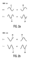
Figure 2a shows the modulation of MSK-sin. The figure shows the variations in a modulated part of the wobble. In the Minimum Shift Keying sinus type (MSK-sin) adata value 0 is represented by a full period of thewobble 21 or aninverted period 22, starting at the zero crossing of the wobble. Thedata value 1 is represented by a frequency which is 1.5 times higher, so apositive starting wobble 23 or anegative starting wobble 24. Hence the MSK modulation is based on sine waves with frequency 1.0 times the wobble frequency (fwob) and sine waves with frequency 1.5*fwob. With MSK-sin the frequency changes at the zero crossings of the wobble signal. At the points where the frequency changes the slope is discontinuous. -
Figure 2b shows the modulation of MSK-cos. The figure shows the variations in a modulated part of the wobble. In the Minimum Shift Keying cosinus type (MSK-cos) adata value 0 is represented by a full period of thewobble 25 or aninverted period 26, starting at the maximum or minimum amplitude of the wobble. Thedata value 1 is represented by a frequency which is 1.5 times higher, so apositive starting wobble 27 or anegative starting wobble 28, also starting at the maximum or minimum. Hence the MSK modulation is based on sine waves with frequency 1.0*fwob and sine waves with frequency 1.5*fwob. With MSK-cos the frequency changes at the maxima or minima of the wobble signal. At the points where the frequency changes the slope is continuous. It is to be noted that all waveforms of the MSK-cos are without a DC component when integrated on the length of one wobble frequency period, whereas the 1.5 * fwob waveform of MSK-sin has a DC component. The DC component may be balanced by an inverted 1.5 * fwob MSK-sin waveform, but the absence of such DC components in the MSK-cos modulation results in less disturbing frequency components in the low frequency range relevant to servo systems. -
Figure 3 shows MSK-sin and MSK-cos signals. The figure shows examples of the modulated wave forms for MSK-sin (32) and MSK-cos (35) for a single data bit. The central traces (32,35) show the wave form on the disc (solid lines) for MSK-sin (left) and MSK-cos (right). For reference, the single-tone sine or cosine signals are also shown (dotted lines). Both examples are for data bit with a length of 3 wobble periods. The first and last parts of such a data bit are described above with reference toFigure 2a and 2b . In the middle period of said 3 periods an inverted wobble is present. The top traces (31,34) show the difference between the MSK-sin (left) and MSK-cos (right) wave forms and a reference not modulated wobble. The bottom traces (33,36) show the result of multiplying the wave forms (32,35) with the reference wobble. -
Figure 4 shows the power spectral density of a data bit. The solid line 41 is the spectrum for MSK-sin, the dashedline 42 is the spectrum for MSK-cos. Thespectrum 42 of MSK-cos is narrower than the spectrum 41 of MSK-sin. In other words, MSK-cos is producing less disturbing frequency components and can be filtered more narrowly by the detector than MSK-sin. The detection performance of MSK-cos will be better compared to MSK-sin, depending on the resulting signal to noise ratio after filtering. -
Figures 5 shows a reading device for scanning arecord carrier 1. Writing and reading of information on optical discs and formatting, error correcting and channel coding rules, are well-known in the art, e.g. from the CD system. The apparatus ofFigure 5 is arranged for reading therecord carrier 1, which record carrier is identical to the record carriers shown inFigure 1 . The device is provided with aread head 52 for scanning the track on the record carrier and read control means comprisingdrive unit 55 for rotating therecord carrier 1, aread circuit 53 for example comprising a channel decoder and an error corrector, trackingunit 51 and asystem control unit 56. The read head comprises optical elements of the usual type for generating aradiation spot 66 focused on a track of the recording layer of the record carrier via aradiation beam 65 guided through optical elements. Theradiation beam 65 is generated by a radiation source, e.g. a laser diode. The read head further comprises a focusing actuator for focusing theradiation beam 65 on the recording layer and a trackingactuator 59 for fine positioning of thespot 66 in radial direction on the center of the track. The apparatus has apositioning unit 54 for coarsely positioning theread head 52 in the radial direction on the track. The trackingactuator 59 may comprise coils for radially moving an optical element or may be arranged for changing the angle of a reflecting element on a movable part of the read head or on a part on a fixed position in the case part of the optical system is mounted on a fixed position. The radiation reflected by the recording layer is detected by a detector of a usual type, e.g. a four-quadrant diode, for generating a detector signals 57 including a read signal, a tracking error and a focusing error signal. Thetracking unit 51 is coupled to the read head for receiving the tracking error signal from the read head and controlling the trackingactuator 59. During reading, the read signal is converted into output information, indicated byarrow 64, in theread circuit 53. The apparatus is provided with anaddress detector 50 for detecting and the retrieving address information from the detector signals 57 when scanning the servo track of the record carrier. The device is further provided with asystem control unit 56 for receiving commands from a controlling computer system or from a user and for controlling the apparatus viacontrol lines 58, e.g. a system bus connected to thedrive unit 55, thepositioning unit 54, theaddress detector 50, thetracking unit 51 and theread circuit 53. To this end, the system control unit comprises control circuitry, for example a microprocessor, a program memory and control gates, for performing the procedures described below. Thesystem control unit 56 may also be implemented as a state machine in logic circuits. The read device is arranged for reading a disc having tracks having a periodic variation, e.g. a continuous wobble. The read control unit are arranged for detecting the periodic variations and for reading in dependence thereon a predetermined amount data from the track. In an embodiment the read clock is synchronized to the periodic variations and theread circuit 53 reads a fixed number of channel bits for each instance of the periodic variations. In an embodiment the read control means are arranged for retrieving the data from an area of the track following an unrecorded area. In theread circuit 53 the read clock is synchronized to the periodic variations in the unrecorded area and the reading speed is adjusted during scanning the unrecorded area. Hence at the start of the recorded area theread circuit 53 is locked in to the speed of the recorded data. In particular theaddress detector 50 is arranged for reading record carrier information, e.g. position information and recording control data, from the modulated signal derived from the modulated wobble. Theaddress detector 50 has a detection unit for detecting modulated wobbles starting at a predefined transition point in the wobble signal, at which transition point the slope of the wobble is continuous. For a sinusoidal wobble having the transitions at the maxima (or minima) the detecting starting point is at said maxima (or minima). In a preferred embodiment theaddress detector 50 includes a matched filter based on the frequency spectrum of the wobble signal. The matched filter improves the signal to noise ratio of the modulated wobble signal, because the frequency spectrum of the wobble signal is narrower than the spectrum of a wobble signal having transitions at the zero crossing. The address detector further has a word detection unit for retrieving the words of record carrier information. The beginning of such a word is detected from a synchronization signal after a long sequence of non modulated wobbles. The occurrence and value of a data bit is detected based on the modulated wobbles. In further embodiments other types of synchronization or decoding of the values of the record carrier information may be applied. -
Figure 6 shows a device for writing information on a record carrier according to the invention of a type which is (re)writable in, for example a magneto-optical or optical manner (via phase change or dye) by means of abeam 65 of electromagnetic radiation. The device is also equipped for reading and comprises the same elements as the apparatus for reading described above withFigure 5 , except that it has a write/read head 62 and recording control means which comprise the same elements as the read control means, except for awrite circuit 60 that comprises for example a formatter, an error encoder and a channel encoder. The write/read head 62 has the same function as theread head 52 together with a write function and is coupled to thewrite circuit 60. The information presented to the input of the write circuit 60 (indicated by the arrow 63) is distributed over logical and physical sectors according to formatting and encoding rules and converted into awrite signal 61 for the write/read head 62. Thesystem control unit 56 is arranged for controlling thewrite circuit 60 and for performing the position information recovery and positioning procedure as described above for the reading apparatus. During the writing operation, marks representing the information are formed on the record carrier. The recording control means are arranged for detecting the periodic variations, for example by locking a phase locked loop to the periodicity thereof. Theaddress detector 50 is described above with reference toFigure 5 . -
Figures 7a and 7b show the power spectral densities (PSDs) for MSK-sin and MSK-cos for two different bit patterns that are repeated periodically.Figure 7a shows for a certain bit pattern thePSD 71 for MSK-sin and thePSD 72 for MSK-cos.Figure 7b shows for another bit pattern thePSD 73 for MSK-sin and thePSD 74 for MSK-cos. It shows that the PSDs for MSK-sin and MSK-cos are substantially the same in the central parts of the spectrum. However, at low frequencies around 0.1*fwob the PSD of MSK-cos is more than 10 dB lower than the PSD of MSK-sin. This is related to the absence of DC content of a one fwob period segment of the MSK-cos signal (for example at 1.5 * fwob), whereas such a one period segment of MSK-sin does have a DC content which is compensated later in the signal at the next (inverse) MSK-sin segment. The low-frequency spectrum of MSK-cos is thus substantially lower than that of MSK-sin which is an advantage because of the lower distortion of the servo. Further, a more smooth wave form for MSK-cos is caused by the continuous slope in contrast to MSK-sin where the slope is discontinuous at the point where the frequency changes. Also in the high frequency range above 2*fwob the PSD for MSK-cos is somewhat lower than the PSD for MSK-cos. Hence less disturbing frequency components are present in the higher frequency ranges also. - Although the invention has been explained by embodiments using a wobble modulation, any other suitable parameter of the track may be modulated, e.g. the track width. Also for the record carrier an optical disc has been described, but other media, such as a magnetic disc or tape, may be used. It is noted, that in this document the word 'comprising' does not exclude the presence of other elements or steps than those listed and the word 'a' or 'an' preceding an element does not exclude the presence of a plurality of such elements, that any reference signs do not limit the scope of the claims, that the invention may be implemented by means of both hardware and software, and that several 'means' may be represented by the same item of hardware.
Claims (12)
- Record carrier comprising a servo track (4) indicating an information track (9) intended for recording information blocks, which servo track (4) has a substantially sinusoidal variation of a physical parameter which variation is predominantly monotonic at a predetermined frequency, and which servo track is modulated for encoding record carrier information by:- non-modulated parts having only said variation at the predetermined frequency, and- modulated parts in which the frequency and/or phase of the variation deviates from the predetermined frequency and/or phase of the non-modulated parts, characterized in that the slope of the variation is substantially continuous at transitions between the modulated and non-modulated parts, and the transitions are located at the minima and/or maxima of said sinusoidal variation.
- Record carrier as claimed in claim 1, wherein a first part of the modulated parts comprises said variation at a deviating frequency, the length of the first part corresponding to m periods (25,26) of the predetermined frequency and corresponding to n + 0.5 periods (27,28) of the deviating frequency, n and m being integers.
- Record carrier as claimed in claim 2, wherein a second part of the modulated parts comprises at least one period of the predetermined frequency of a phase inverse to the phase of the not modulated periodic variations and a third part of the modulated parts comprises said variation at the deviating frequency, the length of the third part corresponding to m periods (25,26) of the predetermined frequency and corresponding to n + 0.5 periods (27,28) of the deviating frequency.
- Record carrier as claimed in claim 2 or 3, wherein the first part has a length corresponding to one period of the predetermined frequency, and n equals 1.
- Record carrier as claimed in claim 1, wherein the modulated parts comprise at least one period of the predetermined frequency of a phase inverse to the phase of the not modulated periodic variations.
- Recording and/or playback device comprising means for writing and/or reading information blocks in an information track (9) on a record carrier as claimed in claim 1, which device comprises means for scanning the servo track (4) and demodulation means for retrieving said modulated record carrier information from a signal generated by said predominantly monotonic variation at said predetermined frequency, characterized in that the demodulation means comprise detection means (50) for detecting the modulated parts starting at transitions between the modulated and non-modulated parts at which the slope of the variation is substantially continuous, the transitions being located at the minima and/or maxima of said sinusoidal variation, and in that the detection means (50) are arranged for detecting starting at said minima and/or maxima.
- Device as claimed in claim 6, wherein the detection means (50) are arranged for detecting modulated parts having a first part comprising said variation at a deviating frequency, the length of the first part corresponding to m periods of the predetermined frequency and corresponding to n + 0.5 periods of the deviating frequency, n and m being integers.
- Device as claimed in claim 7, wherein the detection means (50) are arranged for detecting modulated parts having a second part comprising at least one variation at the predetermined frequency of a phase inverse to the phase of the not modulated periodic variations and a third part comprises said variation at the deviating frequency, the length of the third part corresponding to m periods (25,26) of the predetermined frequency and corresponding to n + 0.5 periods (27,28) of the deviating frequency.
- Device as claimed in claim 7, wherein the detection means (50) are adapted for detecting modulated parts wherein the first part has a length corresponding to one period of the predetermined frequency, and n equals 1.
- Device as claimed in claim 6, wherein the detection means (50) are for detecting a number of periodic variations of a phase inverse to the phase of the not modulated periodic variations.
- Device as claimed in claim 6, wherein the detection means (50) comprise a matched filter based on the frequency spectrum of the signal generated by the modulated parts.
- Method of manufacturing a record carrier as claimed in claim 1, in which the record carrier is provided with a servo track (4) indicating an information track (9) intended for recording information blocks, which servo track (4) is provided with a substantially sinusoidal, predominantly monotonic variation of a physical parameter at a predetermined frequency which variation is modulated for encoding record carrier information by:- non-modulated parts having only said variation at the predetermined frequency, and- modulated parts in which the frequency and/or phase of the variation deviates from the predetermined frequency and/or phase of the non-modulated parts, characterized in that transitions between the modulated and non-modulated parts are provided keeping the slope of the variation substantially continuous, and the transitions are located at the minima and/or maxima of said sinusoidal variation.
Priority Applications (4)
| Application Number | Priority Date | Filing Date | Title |
|---|---|---|---|
| EP02743520A EP1405306B1 (en) | 2001-07-02 | 2002-06-27 | Record carrier and apparatus for scanning the record carrier |
| DK08100910.2T DK1926093T3 (en) | 2001-07-02 | 2002-06-27 | Recording carrier and apparatus for scanning the recording carrier |
| EP08100910A EP1926093B1 (en) | 2001-07-02 | 2002-06-27 | Record carrier and apparatus for scanning the record carrier |
| CY20091101217T CY1109643T1 (en) | 2001-07-02 | 2009-11-25 | REGISTRATION BODY AND DEVICE FOR SCANING THE REGISTRATION BODY |
Applications Claiming Priority (4)
| Application Number | Priority Date | Filing Date | Title |
|---|---|---|---|
| EP01202545 | 2001-07-02 | ||
| EP01202545 | 2001-07-02 | ||
| EP02743520A EP1405306B1 (en) | 2001-07-02 | 2002-06-27 | Record carrier and apparatus for scanning the record carrier |
| PCT/IB2002/002736 WO2003005350A1 (en) | 2001-07-02 | 2002-06-27 | Record carrier and apparatus for scanning the record carrier |
Related Child Applications (1)
| Application Number | Title | Priority Date | Filing Date |
|---|---|---|---|
| EP08100910A Division EP1926093B1 (en) | 2001-07-02 | 2002-06-27 | Record carrier and apparatus for scanning the record carrier |
Publications (2)
| Publication Number | Publication Date |
|---|---|
| EP1405306A1 EP1405306A1 (en) | 2004-04-07 |
| EP1405306B1 true EP1405306B1 (en) | 2009-08-26 |
Family
ID=8180582
Family Applications (2)
| Application Number | Title | Priority Date | Filing Date |
|---|---|---|---|
| EP08100910A Expired - Lifetime EP1926093B1 (en) | 2001-07-02 | 2002-06-27 | Record carrier and apparatus for scanning the record carrier |
| EP02743520A Expired - Lifetime EP1405306B1 (en) | 2001-07-02 | 2002-06-27 | Record carrier and apparatus for scanning the record carrier |
Family Applications Before (1)
| Application Number | Title | Priority Date | Filing Date |
|---|---|---|---|
| EP08100910A Expired - Lifetime EP1926093B1 (en) | 2001-07-02 | 2002-06-27 | Record carrier and apparatus for scanning the record carrier |
Country Status (26)
| Country | Link |
|---|---|
| US (3) | US7274627B2 (en) |
| EP (2) | EP1926093B1 (en) |
| JP (2) | JP4490686B2 (en) |
| KR (1) | KR100900733B1 (en) |
| CN (2) | CN101025989B (en) |
| AR (1) | AR034683A1 (en) |
| AT (2) | ATE441180T1 (en) |
| BR (1) | BRPI0205695B1 (en) |
| CO (1) | CO5550510A2 (en) |
| CY (2) | CY1109643T1 (en) |
| DE (2) | DE60233498D1 (en) |
| DK (2) | DK1405306T3 (en) |
| EA (1) | EA005639B1 (en) |
| EG (1) | EG23269A (en) |
| ES (2) | ES2331873T3 (en) |
| HK (1) | HK1064206A1 (en) |
| HR (1) | HRP20030143B1 (en) |
| IL (1) | IL159668A0 (en) |
| MA (1) | MA26205A1 (en) |
| MX (1) | MXPA03001745A (en) |
| MY (1) | MY149315A (en) |
| NO (1) | NO20030927L (en) |
| PT (2) | PT1926093E (en) |
| TN (1) | TNSN03009A1 (en) |
| TW (1) | TWI233607B (en) |
| WO (1) | WO2003005350A1 (en) |
Families Citing this family (22)
| Publication number | Priority date | Publication date | Assignee | Title |
|---|---|---|---|---|
| ATE441180T1 (en) * | 2001-07-02 | 2009-09-15 | Koninkl Philips Electronics Nv | RECORDING MEDIUM AND DEVICE FOR SCANNING THE RECORDING MEDIUM |
| JP4652641B2 (en) * | 2001-10-11 | 2011-03-16 | ソニー株式会社 | Disc recording medium, disc drive apparatus, and playback method |
| JP3789423B2 (en) | 2001-11-17 | 2006-06-21 | エルジー電子株式会社 | Apparatus and method for encoding wobble signal recorded on optical disk, and apparatus and method for decoding wobble signal read from optical disk |
| TWI298156B (en) | 2002-10-24 | 2008-06-21 | Tian Holdings Llc | Discrimination method for light storage device |
| CN100377219C (en) * | 2003-03-31 | 2008-03-26 | 上海乐金广电电子有限公司 | Demodulation device/method of optical disk dither signal and demodulation device/method thereof |
| EP1489611A1 (en) * | 2003-06-16 | 2004-12-22 | Deutsche Thomson-Brandt Gmbh | Wobble demodulation for high density optical recording media |
| EP1489612B1 (en) * | 2003-06-16 | 2017-05-03 | Thomson Licensing | Wobble demodulation for high density optical recording media |
| TWI316702B (en) | 2003-09-15 | 2009-11-01 | Tian Holdings Llc | Discriminating method of an optical disc device for ascertaining the format of an loaded optical disc |
| DE10345950A1 (en) | 2003-10-02 | 2005-05-19 | Pari GmbH Spezialisten für effektive Inhalation | Inhalation therapy device with valve |
| US20050226114A1 (en) | 2004-03-31 | 2005-10-13 | Stanley Liow | Method and apparatus for generating absolute time in pregroove data |
| JP4114605B2 (en) * | 2003-12-24 | 2008-07-09 | ソニー株式会社 | Information processing apparatus, information recording medium, information processing method, and computer program |
| US7570561B2 (en) | 2004-05-25 | 2009-08-04 | Bryan Tai | Method for determining type of digital versatile discs |
| US7746745B2 (en) | 2004-05-25 | 2010-06-29 | Ricky Chang | Method for determining the type of digital versatile disc |
| US7626907B2 (en) | 2004-05-25 | 2009-12-01 | Ricky Chang | Method and apparatus for determining type of digital versatile disc |
| WO2005117008A1 (en) * | 2004-05-25 | 2005-12-08 | Via Technologies, Inc. | Method and apparatus for type determination of digital versatile discs |
| US7161753B2 (en) * | 2005-01-28 | 2007-01-09 | Komag, Inc. | Modulation of sidewalls of servo sectors of a magnetic disk and the resultant disk |
| FR2898226B1 (en) * | 2006-03-06 | 2009-03-06 | Excem Soc Par Actions Simplifi | ELECTROLUMINESCENT TRANSMISSION DEVICE FOR OPTICAL TRANSMISSION IN FREE SPACE |
| FR2907272B1 (en) * | 2006-10-13 | 2008-12-26 | Commissariat Energie Atomique | METHOD FOR MANAGING THE END OF DISCHARGE OF A RECHARGEABLE BATTERY |
| TWI347596B (en) | 2007-01-11 | 2011-08-21 | Ind Tech Res Inst | Optical recording carrier, signal generating apparatus, information recording method, and information reading apparatus |
| JPWO2012063326A1 (en) * | 2010-11-09 | 2014-05-12 | 株式会社東芝 | Information recording medium, information reproducing apparatus, and information recording apparatus |
| US8582405B1 (en) * | 2012-09-25 | 2013-11-12 | Oracle International Corporation | Matched pattern signal decoding |
| KR20200086512A (en) * | 2019-01-09 | 2020-07-17 | 한국전자통신연구원 | Method and apparatus for backscatter communication in pattern-based demodulation |
Family Cites Families (24)
| Publication number | Priority date | Publication date | Assignee | Title |
|---|---|---|---|---|
| JPS57158057A (en) * | 1981-03-25 | 1982-09-29 | Sony Corp | Correcting method for wow and flutter |
| NL8800151A (en) * | 1988-01-22 | 1989-08-16 | Philips Nv | METHOD AND APPARATUS FOR RECORDING AN INFORMATION SIGNAL |
| NL8800152A (en) | 1988-01-22 | 1989-08-16 | Philips Nv | OPTICAL READABLE RECORD CARRIER OF THE DESCRIBABLE TYPE, AN APPARATUS FOR MANUFACTURING SUCH RECORD CARRIER, AND ARRANGEMENTS FOR RECORDING AND / OR READING INFORMATION ON / FROM SUCH RECORD CARRIER. |
| US5363360A (en) * | 1993-09-27 | 1994-11-08 | Eastman Kodak Company | Method and apparatus for detecting and processing synchronization marks extracted from a prerecorded wobbled groove on a compact disk |
| JPH1069646A (en) * | 1996-08-29 | 1998-03-10 | Ricoh Co Ltd | Optical disk medium, optical disk device |
| DE69728755T2 (en) * | 1996-11-18 | 2005-04-07 | Koninklijke Philips Electronics N.V. | RECORDING DEVICE AND SUPPORT AND RECORDING AND READING DEVICE FOR INFORMATION BLOCKS |
| JPH10208249A (en) | 1997-01-21 | 1998-08-07 | Sony Corp | Optical disk |
| CN1204120A (en) * | 1997-05-08 | 1999-01-06 | 索尼株式会社 | Frequency demodulating circuit, optical disk apparatus thereof and preforming device |
| US6310838B1 (en) * | 1997-09-03 | 2001-10-30 | U.S. Philips Corporation | Record carrier and apparatus for scanning the record carrier |
| JP3339436B2 (en) * | 1998-12-08 | 2002-10-28 | 住友金属工業株式会社 | Mold powder for continuous casting |
| WO2000043996A1 (en) * | 1999-01-25 | 2000-07-27 | Koninklijke Philips Electronics N.V. | Record carrier and apparatus for scanning the record carrier |
| JP4099914B2 (en) * | 1999-12-10 | 2008-06-11 | ソニー株式会社 | Optical disc and optical disc apparatus |
| JP2001338421A (en) * | 2000-03-21 | 2001-12-07 | Sony Corp | Disk drive device and wobble information generating method |
| AU2002218456A1 (en) * | 2000-12-11 | 2002-06-24 | Koninklijke Philips Electronics N.V. | Record carrier of the optical type and a device for recording and/or playback for use with such a record carrier |
| JP2002237096A (en) * | 2001-02-09 | 2002-08-23 | Ricoh Co Ltd | Optical recording medium |
| JP5175413B2 (en) * | 2001-03-12 | 2013-04-03 | ソニー株式会社 | Disc recording medium, reproducing device, recording device |
| TWI229854B (en) * | 2001-03-16 | 2005-03-21 | Koninkl Philips Electronics Nv | Record carrier and apparatus for scanning the record carrier |
| KR100727916B1 (en) * | 2001-05-02 | 2007-06-13 | 삼성전자주식회사 | A optical disc |
| KR100408285B1 (en) * | 2001-05-24 | 2003-12-03 | 삼성전자주식회사 | Optical recording medium on which multi-modulated header signals are recorded, method and apparatus for recording the header signals, method and apparatus for reproducing the header signals |
| ATE441180T1 (en) | 2001-07-02 | 2009-09-15 | Koninkl Philips Electronics Nv | RECORDING MEDIUM AND DEVICE FOR SCANNING THE RECORDING MEDIUM |
| PT1440440E (en) * | 2001-10-15 | 2012-11-14 | Koninkl Philips Electronics Nv | Record carrier and apparatus for scanning the record carrier |
| JP4121264B2 (en) * | 2001-10-16 | 2008-07-23 | コーニンクレッカ フィリップス エレクトロニクス エヌ ヴィ | Disk drive device and wobble information detection method |
| JP3789423B2 (en) * | 2001-11-17 | 2006-06-21 | エルジー電子株式会社 | Apparatus and method for encoding wobble signal recorded on optical disk, and apparatus and method for decoding wobble signal read from optical disk |
| AU2003233100A1 (en) * | 2003-05-27 | 2005-01-21 | Koninklijke Philips Electronics N.V. | Bit synchronization detection means |
-
2002
- 2002-06-27 AT AT02743520T patent/ATE441180T1/en active
- 2002-06-27 IL IL15966802A patent/IL159668A0/en not_active IP Right Cessation
- 2002-06-27 ES ES02743520T patent/ES2331873T3/en not_active Expired - Lifetime
- 2002-06-27 PT PT08100910T patent/PT1926093E/en unknown
- 2002-06-27 PT PT02743520T patent/PT1405306E/en unknown
- 2002-06-27 WO PCT/IB2002/002736 patent/WO2003005350A1/en active Application Filing
- 2002-06-27 DE DE60233498T patent/DE60233498D1/en not_active Expired - Lifetime
- 2002-06-27 AT AT08100910T patent/ATE474314T1/en active
- 2002-06-27 DE DE60237051T patent/DE60237051D1/en not_active Expired - Lifetime
- 2002-06-27 EP EP08100910A patent/EP1926093B1/en not_active Expired - Lifetime
- 2002-06-27 CN CN2007100063439A patent/CN101025989B/en not_active Expired - Fee Related
- 2002-06-27 BR BRPI0205695-0A patent/BRPI0205695B1/en active IP Right Grant
- 2002-06-27 TN TNPCT/IB2002/002736A patent/TNSN03009A1/en unknown
- 2002-06-27 ES ES08100910T patent/ES2348846T3/en not_active Expired - Lifetime
- 2002-06-27 DK DK02743520T patent/DK1405306T3/en active
- 2002-06-27 MX MXPA03001745A patent/MXPA03001745A/en active IP Right Grant
- 2002-06-27 KR KR1020037002917A patent/KR100900733B1/en active IP Right Grant
- 2002-06-27 EA EA200400133A patent/EA005639B1/en not_active IP Right Cessation
- 2002-06-27 EP EP02743520A patent/EP1405306B1/en not_active Expired - Lifetime
- 2002-06-27 US US10/481,143 patent/US7274627B2/en not_active Expired - Lifetime
- 2002-06-27 JP JP2003511236A patent/JP4490686B2/en not_active Expired - Lifetime
- 2002-06-27 CN CNB028132734A patent/CN100370525C/en not_active Expired - Lifetime
- 2002-06-27 DK DK08100910.2T patent/DK1926093T3/en active
- 2002-07-01 EG EG2002070765A patent/EG23269A/en active
- 2002-07-01 MY MYPI20022483A patent/MY149315A/en unknown
- 2002-07-02 AR ARP020102486A patent/AR034683A1/en active IP Right Grant
- 2002-08-26 TW TW091119243A patent/TWI233607B/en not_active IP Right Cessation
-
2003
- 2003-02-27 NO NO20030927A patent/NO20030927L/en not_active Application Discontinuation
- 2003-02-27 HR HR20030143A patent/HRP20030143B1/en not_active IP Right Cessation
- 2003-11-28 CO CO03105190A patent/CO5550510A2/en not_active Application Discontinuation
-
2004
- 2004-01-02 MA MA27471A patent/MA26205A1/en unknown
- 2004-09-13 HK HK04106921.7A patent/HK1064206A1/en not_active IP Right Cessation
-
2007
- 2007-08-27 US US11/845,140 patent/US8644119B2/en active Active
-
2009
- 2009-09-17 JP JP2009215539A patent/JP4649528B2/en not_active Expired - Fee Related
- 2009-11-25 CY CY20091101217T patent/CY1109643T1/en unknown
-
2010
- 2010-10-06 CY CY20101100889T patent/CY1110818T1/en unknown
-
2013
- 2013-12-30 US US14/143,073 patent/US9449642B2/en not_active Expired - Fee Related
Non-Patent Citations (2)
| Title |
|---|
| KOBAYASHI ET AL: "Wobble Address Format of the Blu-ray Disc", JAPANESE JOURNAL OF APPLIED PHYSICS, vol. 42, 2003, pages 915 - 918, XP001155099 * |
| KUIJPER ET AL: "Groove only recording under DVR conditions", PROCEEDINGS SPIE, vol. 4342, 2002, pages 178 - 185, XP002371452 * |
Also Published As
Similar Documents
| Publication | Publication Date | Title |
|---|---|---|
| US8644119B2 (en) | Record carrier and apparatus for scanning the record carrier | |
| CA2325450C (en) | Record carrier and apparatus for scanning the record carrier | |
| USRE44088E1 (en) | Record carrier having a servo track with position information in accordance with a modulation type and permanent information in accordance with a different modulation type, and apparatus for scanning the record carrier | |
| JP2004534346A5 (en) | ||
| AU2002339218A1 (en) | Record carrier and apparatus for scanning the record carrier | |
| US7158472B2 (en) | Record carrier and apparatus for scanning the record carrier | |
| AU2002337404A1 (en) | Record carrier and apparatus for scanning the record | |
| ZA200005068B (en) | Record carrier and apparatus for scanning the record carrier. |
Legal Events
| Date | Code | Title | Description |
|---|---|---|---|
| PUAI | Public reference made under article 153(3) epc to a published international application that has entered the european phase |
Free format text: ORIGINAL CODE: 0009012 |
|
| 17P | Request for examination filed |
Effective date: 20040202 |
|
| AK | Designated contracting states |
Kind code of ref document: A1 Designated state(s): AT BE CH CY DE DK ES FI FR GB GR IE IT LI LU MC NL PT SE TR |
|
| AX | Request for extension of the european patent |
Extension state: AL LT LV MK RO SI |
|
| REG | Reference to a national code |
Ref country code: HK Ref legal event code: DE Ref document number: 1064206 Country of ref document: HK |
|
| 17Q | First examination report despatched |
Effective date: 20080114 |
|
| GRAP | Despatch of communication of intention to grant a patent |
Free format text: ORIGINAL CODE: EPIDOSNIGR1 |
|
| GRAS | Grant fee paid |
Free format text: ORIGINAL CODE: EPIDOSNIGR3 |
|
| GRAA | (expected) grant |
Free format text: ORIGINAL CODE: 0009210 |
|
| AK | Designated contracting states |
Kind code of ref document: B1 Designated state(s): AT BE CH CY DE DK ES FI FR GB GR IE IT LI LU MC NL PT SE TR |
|
| REG | Reference to a national code |
Ref country code: GB Ref legal event code: FG4D |
|
| REG | Reference to a national code |
Ref country code: CH Ref legal event code: EP |
|
| REG | Reference to a national code |
Ref country code: IE Ref legal event code: FG4D |
|
| REF | Corresponds to: |
Ref document number: 60233498 Country of ref document: DE Date of ref document: 20091008 Kind code of ref document: P |
|
| REG | Reference to a national code |
Ref country code: PT Ref legal event code: SC4A Free format text: AVAILABILITY OF NATIONAL TRANSLATION Effective date: 20091110 |
|
| REG | Reference to a national code |
Ref country code: DK Ref legal event code: T3 |
|
| REG | Reference to a national code |
Ref country code: SE Ref legal event code: TRGR |
|
| REG | Reference to a national code |
Ref country code: GR Ref legal event code: EP Ref document number: 20090402770 Country of ref document: GR |
|
| REG | Reference to a national code |
Ref country code: ES Ref legal event code: FG2A Ref document number: 2331873 Country of ref document: ES Kind code of ref document: T3 |
|
| REG | Reference to a national code |
Ref country code: HK Ref legal event code: GR Ref document number: 1064206 Country of ref document: HK |
|
| PLBE | No opposition filed within time limit |
Free format text: ORIGINAL CODE: 0009261 |
|
| STAA | Information on the status of an ep patent application or granted ep patent |
Free format text: STATUS: NO OPPOSITION FILED WITHIN TIME LIMIT |
|
| 26N | No opposition filed |
Effective date: 20100527 |
|
| REG | Reference to a national code |
Ref country code: ES Ref legal event code: PC2A Owner name: KONINKLIJKE PHILIPS N.V. Effective date: 20140221 |
|
| REG | Reference to a national code |
Ref country code: DE Ref legal event code: R082 Ref document number: 60233498 Country of ref document: DE Representative=s name: VOLMER, GEORG, DIPL.-ING., DE |
|
| REG | Reference to a national code |
Ref country code: DE Ref legal event code: R081 Ref document number: 60233498 Country of ref document: DE Owner name: KONINKLIJKE PHILIPS N.V., NL Free format text: FORMER OWNER: KONINKLIJKE PHILIPS ELECTRONICS N.V., EINDHOVEN, NL Effective date: 20140328 Ref country code: DE Ref legal event code: R082 Ref document number: 60233498 Country of ref document: DE Representative=s name: MEISSNER, BOLTE & PARTNER GBR, DE Effective date: 20140328 Ref country code: DE Ref legal event code: R082 Ref document number: 60233498 Country of ref document: DE Representative=s name: MEISSNER BOLTE PATENTANWAELTE RECHTSANWAELTE P, DE Effective date: 20140328 Ref country code: DE Ref legal event code: R082 Ref document number: 60233498 Country of ref document: DE Representative=s name: VOLMER, GEORG, DIPL.-ING., DE Effective date: 20140328 |
|
| REG | Reference to a national code |
Ref country code: FR Ref legal event code: CA Effective date: 20141126 Ref country code: FR Ref legal event code: CD Owner name: KONINKLIJKE PHILIPS ELECTRONICS N.V., NL Effective date: 20141126 |
|
| REG | Reference to a national code |
Ref country code: DE Ref legal event code: R082 Ref document number: 60233498 Country of ref document: DE Representative=s name: MEISSNER, BOLTE & PARTNER GBR, DE Ref country code: DE Ref legal event code: R082 Ref document number: 60233498 Country of ref document: DE Representative=s name: MEISSNER BOLTE PATENTANWAELTE RECHTSANWAELTE P, DE |
|
| REG | Reference to a national code |
Ref country code: FR Ref legal event code: PLFP Year of fee payment: 15 |
|
| REG | Reference to a national code |
Ref country code: FR Ref legal event code: PLFP Year of fee payment: 16 |
|
| REG | Reference to a national code |
Ref country code: FR Ref legal event code: PLFP Year of fee payment: 17 |
|
| PGFP | Annual fee paid to national office [announced via postgrant information from national office to epo] |
Ref country code: MC Payment date: 20180625 Year of fee payment: 17 Ref country code: FI Payment date: 20180622 Year of fee payment: 17 Ref country code: LU Payment date: 20180629 Year of fee payment: 17 Ref country code: IE Payment date: 20180625 Year of fee payment: 17 |
|
| REG | Reference to a national code |
Ref country code: FI Ref legal event code: MAE |
|
| PG25 | Lapsed in a contracting state [announced via postgrant information from national office to epo] |
Ref country code: CY Free format text: LAPSE BECAUSE OF NON-PAYMENT OF DUE FEES Effective date: 20190627 Ref country code: MC Free format text: LAPSE BECAUSE OF NON-PAYMENT OF DUE FEES Effective date: 20190701 Ref country code: FI Free format text: LAPSE BECAUSE OF NON-PAYMENT OF DUE FEES Effective date: 20190627 |
|
| PG25 | Lapsed in a contracting state [announced via postgrant information from national office to epo] |
Ref country code: IE Free format text: LAPSE BECAUSE OF NON-PAYMENT OF DUE FEES Effective date: 20190627 |
|
| PG25 | Lapsed in a contracting state [announced via postgrant information from national office to epo] |
Ref country code: LU Free format text: LAPSE BECAUSE OF NON-PAYMENT OF DUE FEES Effective date: 20190627 |
|
| PGFP | Annual fee paid to national office [announced via postgrant information from national office to epo] |
Ref country code: DE Payment date: 20210628 Year of fee payment: 20 Ref country code: FR Payment date: 20210625 Year of fee payment: 20 Ref country code: IT Payment date: 20210622 Year of fee payment: 20 Ref country code: GR Payment date: 20210625 Year of fee payment: 20 Ref country code: NL Payment date: 20210628 Year of fee payment: 20 Ref country code: PT Payment date: 20210614 Year of fee payment: 20 |
|
| PGFP | Annual fee paid to national office [announced via postgrant information from national office to epo] |
Ref country code: SE Payment date: 20210622 Year of fee payment: 20 Ref country code: AT Payment date: 20210618 Year of fee payment: 20 Ref country code: BE Payment date: 20210628 Year of fee payment: 20 Ref country code: GB Payment date: 20210625 Year of fee payment: 20 Ref country code: CH Payment date: 20210622 Year of fee payment: 20 Ref country code: DK Payment date: 20210622 Year of fee payment: 20 |
|
| PGFP | Annual fee paid to national office [announced via postgrant information from national office to epo] |
Ref country code: ES Payment date: 20210709 Year of fee payment: 20 |
|
| REG | Reference to a national code |
Ref country code: DE Ref legal event code: R071 Ref document number: 60233498 Country of ref document: DE |
|
| REG | Reference to a national code |
Ref country code: NL Ref legal event code: MK Effective date: 20220626 |
|
| PG25 | Lapsed in a contracting state [announced via postgrant information from national office to epo] |
Ref country code: TR Free format text: LAPSE BECAUSE OF NON-PAYMENT OF DUE FEES Effective date: 20190627 |
|
| REG | Reference to a national code |
Ref country code: DK Ref legal event code: EUP Expiry date: 20220627 |
|
| REG | Reference to a national code |
Ref country code: BE Ref legal event code: MK Effective date: 20220627 |
|
| REG | Reference to a national code |
Ref country code: CH Ref legal event code: PL |
|
| REG | Reference to a national code |
Ref country code: GB Ref legal event code: PE20 Expiry date: 20220626 |
|
| PG25 | Lapsed in a contracting state [announced via postgrant information from national office to epo] |
Ref country code: GB Free format text: LAPSE BECAUSE OF EXPIRATION OF PROTECTION Effective date: 20220626 |
|
| REG | Reference to a national code |
Ref country code: SE Ref legal event code: EUG |
|
| REG | Reference to a national code |
Ref country code: ES Ref legal event code: FD2A Effective date: 20220805 |
|
| REG | Reference to a national code |
Ref country code: AT Ref legal event code: MK07 Ref document number: 441180 Country of ref document: AT Kind code of ref document: T Effective date: 20220627 |
|
| PG25 | Lapsed in a contracting state [announced via postgrant information from national office to epo] |
Ref country code: PT Free format text: LAPSE BECAUSE OF EXPIRATION OF PROTECTION Effective date: 20220707 Ref country code: ES Free format text: LAPSE BECAUSE OF EXPIRATION OF PROTECTION Effective date: 20220628 |