JP4467207B2 - Resin sealing method and substrate clamping mechanism - Google Patents
Resin sealing method and substrate clamping mechanism Download PDFInfo
- Publication number
- JP4467207B2 JP4467207B2 JP2001143251A JP2001143251A JP4467207B2 JP 4467207 B2 JP4467207 B2 JP 4467207B2 JP 2001143251 A JP2001143251 A JP 2001143251A JP 2001143251 A JP2001143251 A JP 2001143251A JP 4467207 B2 JP4467207 B2 JP 4467207B2
- Authority
- JP
- Japan
- Prior art keywords
- stage
- mold
- substrate
- resin
- rigid member
- Prior art date
- Legal status (The legal status is an assumption and is not a legal conclusion. Google has not performed a legal analysis and makes no representation as to the accuracy of the status listed.)
- Expired - Fee Related
Links
Images


Landscapes
- Casting Or Compression Moulding Of Plastics Or The Like (AREA)
- Encapsulation Of And Coatings For Semiconductor Or Solid State Devices (AREA)
Description
【0001】
【発明の属する技術分野】
本発明は、リードフレームやプリント基板等からなる配線部材(以下、基板という。)に半導体チップ等のチップ状部品を樹脂封止する際に、基板を適正な圧力でクランプして樹脂封止する樹脂封止方法及び基板クランプ機構に関するものである。
【0002】
【従来の技術】
従来、樹脂封止装置の金型が有するキャビティに溶融樹脂を注入して、そのキャビティに収容されたチップ状部品を樹脂封止する際には、次のようにして行っていた。まず、下型側のステージの上に、チップ状部品が装着された基板を載置して、上型と下型とを型締めする。次に、上型に設けられたキャビティに溶融樹脂を注入して、これを硬化させる。次に、型開きして、樹脂封止が完了したパッケージを取り出す。
ここで、溶融樹脂が金型間に漏れ出してしまうと、樹脂ばりが発生する。これを防止するために、従来のクランプ機構では、下型本体とステージとの間にばねを設けて、ばねによる圧力で基板をクランプしている。
【0003】
【発明が解決しようとする課題】
しかしながら、上記従来の樹脂封止方法によれば、基板をクランプする際の圧力(クランプ圧)がキャビティに注入される溶融樹脂の圧力(樹脂圧)よりも小さい場合には、溶融樹脂が漏れ出して樹脂ばりが発生するので、これを防止するためにクランプ圧を樹脂圧よりも大きくする必要がある。クランプ圧は、基板の材質や大きさ、樹脂圧等によって差があり、例えば、5〜12kg/mm2程度に設定されている。
ここで、次のような問題がある。第1の問題は、クランプ圧が大きすぎる場合には、基板にクラックや変形等が発生することである。特に、近年では、パッケージに対して薄型化の要求が強く、基板が薄くなる傾向にあるので、クランプ圧を適正に保つ必要性がますます大きくなっている。第2の問題は、クランプ圧を樹脂圧よりも大きくしなければならないのでばね定数が大きいばねを使用する必要があり、このために、基板の厚さがばらつく場合にはクランプ圧を一定に保つことが困難になることである。したがって、樹脂ばり、基板のクラックや変形等が発生しやすい。
【0004】
本発明は、上述の課題を解決するためになされたものであり、樹脂封止する際に、基板にクラックや変形等が発生しない適正な圧力で基板をクランプするとともに、樹脂ばりを防止する樹脂封止方法及び基板クランプ機構を提供することを目的とする。
【0005】
【課題を解決するための手段】
上述の技術的課題を解決するために、本発明に係る樹脂封止方法は、キャビティが設けられ相対向する金型セットを使用してチップ状部品を樹脂封止する樹脂封止方法であって、チップ状部品が装着された基板を金型セットのうち一方の金型側に設けられたステージの上に載置する工程と、金型セットを型締めすることによって基板をクランプするとともに、該基板をクランプするクランプ圧をステージに当接して設けられた弾性部材に該ステージを介して加えることによってステージを押し込む工程と、一方の金型に設けられた剛性部材をステージに当接させることによって、押し込められたステージを支持する工程と、キャビティに溶融樹脂を注入するとともに、該溶融樹脂を注入する際の樹脂圧をステージを介して剛性部材に加える工程と、溶融樹脂を硬化させる工程と、金型セットを型開きしてチップ状部品が樹脂封止されたパッケージを取り出す工程とを備え、ステージは剛性部材に対向する側にテーパ面を有し、剛性部材はステージのテーパ面に対向するテーパ面を有し、ステージを支持する工程では、剛性部材を前進させてテーパ面同士を互いに当接させることによって、押し込められたステージを支持することを特徴とする。
【0006】
これによれば、型締めした際に、基板に対するクランプ圧をステージを介して弾性部材に加えることになるので、基板には、弾性部材によって定まるクランプ圧しか加わらない。したがって、適当な弾性部材を使用することにより、常に最適なクランプ圧で基板をクランプすることができる。また、キャビティに溶融樹脂を注入する際に、樹脂圧を剛性部材に加えることになるので、クランプされた基板と金型セットとの間に間隙が発生しない。したがって、溶融樹脂の漏出による樹脂ばりの発生を抑制することができる。また、基板の厚さが異なる場合であっても、テーパ面を有する剛性部材を前進させてそのテーパ面とステージのテーパ面とを当接させることにより、ステージを支持することができる。したがって、異なる厚さを有する基板に対しても、クランプされた基板と金型セットとの間に間隙が発生しないので、溶融樹脂の漏出による樹脂ばりの発生を抑制することができる。
【0007】
【0008】
【0009】
上述の技術的課題を解決するために、本発明に係る基板クランプ機構は、
基板上のチップ状部品を樹脂封止する際に使用される基板クランプ機構であって、相対向して設けられた金型セットのうちの一方の金型と、金型セットのうち一方の金型に対向して設けられた他方の金型と、一方の金型に設けられ基板が載置されるステージと、一方の金型において、ステージが有する面のうち基板が載置される面の反対面に当接して設けられた弾性部材と、一方の金型においてステージの反対面に対して離間と当接とが可能になるようにして設けられた剛性部材とを備えているとともに、一方の金型と他方の金型とが型締めされた状態において、基板がクランプされるクランプ圧がステージを介して弾性部材に加えられることによってステージが押し込まれ、かつ、剛性部材がステージに当接可能であり、ステージの反対面はテーパ面からなり、剛性部材はステージのテーパ面に対向するテーパ面を有し、剛性部材が前進してテーパ面同士が互いに当接することによって、押し込められたステージが支持されることを特徴とする。
【0010】
これによれば、型締めされた際に、基板に対するクランプ圧がステージを介して弾性部材に加えられることになるので、基板には、弾性部材によって定まるクランプ圧しか加わらない。したがって、適当な弾性部材を使用することにより、常に最適なクランプ圧で基板がクランプされる。また、型締めされた状態でステージと剛性部材とが当接可能なので、樹脂封止による樹脂圧がステージを介して剛性部材に加えられることが可能になる。これにより、クランプされた基板と金型セットとの間に間隙が発生しない。したがって、溶融樹脂の漏出による樹脂ばりの発生が抑制される。また、基板の厚さが異なる場合であっても、テーパ面を有する剛性部材が前進してそのテーパ面とステージのテーパ面とが当接するので、テーパ部材によってステージが支持される。したがって、異なる厚さを有する基板に対しても、クランプされた基板と金型セットとの間に間隙が発生しないので、溶融樹脂の漏出による樹脂ばりの発生が抑制される。
【0011】
【0012】
【0013】
【発明の実施の形態】
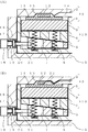
本発明に係る樹脂封止方法及び基板クランプ機構を、図1〜図3を参照して説明する。図1(A),(B)は、本発明に係る樹脂封止方法において、上型が基板に接触した時点の状態と、金型を型締めした後に進退用の可動テーパ部材が前進する直前の状態とをそれぞれ示す部分断面図である。
【0014】
図1において、1は樹脂封止装置の下型、2は下型1に対向して設けられた上型である。3は下型1と上型2とからなる金型セットであって、この金型セット3は、ヒータ(図示せず)により180℃程度にまで予熱されている。4は、下型1に設けられた凹部である。5は、凹部4において水平方向(図の左右方向)に移動可能に設けられた剛性部材であって、上面がテーパ面になっている進退用の可動テーパ部材である。6は、上面が平面で、かつ、下面がテーパ面になっているとともに、その下面が可動テーパ部材5の上面に相対向するように、すなわちテーパ面同士が相対向して設けられている、ステージ用テーパ部材である。7は、可動テーパ部材5とステージ用テーパ部材6とに、可動テーパ部材5の初期位置においてそれぞれ重なるようにして設けられた貫通穴である。8は、貫通穴7に弾性部材として設けられた、例えばコイルばねからなる圧縮ばねである。9は、その下面にステージ用テーパ部材6の上面が当接された状態でステージ用テーパ部材6が固定されており、可動テーパ部材5の初期位置において圧縮ばね8により支持されている基板載置台である。10は、ステージ用テーパ部材6と基板載置台9とにより構成されるステージである。11はステージ10の上に載置された基板、12は基板11に装着された半導体チップである。
【0015】
ここで、ステージ10は、上型2の型面が基板11の上面に接触している状態において、圧縮ばね8により次のようにして支持されている。第1に、ステージ10は、上型2の型面が基板11の上面に接触した時点では、基板11の上面が下型1の型面から突出するようにして、支持されている。第2に、ステージ10は、図1(B)に示すように、金型セット3が型締めした状態では、ステージ10の下面が可動テーパ部材5の上面から離間するようにして、すなわちテーパ面同士が互いに離間するようにして、支持されている。
【0016】
13は、上型2に設けられた空間であって、半導体チップ12が収容されるとともに溶融樹脂が注入されるキャビティである。14は、溶融樹脂の樹脂通路であって、溶融樹脂の供給源であるカル(図示なし)に連通している。
【0017】
15は、下型1が収容されるベースである。16はベース15の側面に取り付けられたエアシリンダ、17はエアシリンダ16のロッドである。18は、ベース15の側壁に設けられた空間である。19は、空間18に設けられ、ロッド17によって突き出される突き出し板である。20は、空間18に設けられ、ロッド17が突き出していない場合に、突き出し板19を初期位置に戻すための圧縮ばねである。21は、突き出し板19と一体的に形成され、先端が可動テーパ部材5に固定された突き出し棒である。
【0018】
図1の樹脂封止方法を、図1と図2とを参照しながら説明する。図2(A),(B)は、本発明に係る樹脂封止方法において、剛性部材がステージを支持する状態と、キャビティに溶融樹脂を注入する状態とをそれぞれ示す部分断面図である。
【0019】
まず、図1(A)に示すように、ロッド17が突き出していない状態、すなわち可動テーパ部材5が初期位置にある状態で、上型2を、その型面が基板11の上面に接触するまで下降させる。前述のように、この時点でステージ10は、基板11の上面が下型1の型面から突出するようにして、圧縮ばね8により支持されている。
【0020】
次に、図1(B)に示すように、上型2と下型1との型面同士が接触するまで引き続き上型2を下降させる。このことによって、金型セット3による型締めが完了する。前述のように、この時点でステージ10は、その下面、すなわちテーパ面が可動テーパ部材5のテーパ面から離間するようにして、すなわちテーパ面同士が互いに離間するようにして、圧縮ばね8により支持されている。
【0021】
次に、同じく図1(B)に示すように、エアシリンダ16を動作させて、ロッド17によって突き出し棒21を突き出す。そして、図2(A)に示すように、ステージ10のテーパ面に当接するまで、可動テーパ部材5を図の右側へと前進させる。これにより、可動テーパ部材5のテーパ面とステージ10のテーパ面とが当接した状態になる。この状態で、金型セット3による型締め圧が、ステージ10を介して、剛性部材である可動テーパ部材5に加えられているとともに、圧縮ばね8によるクランプ圧が、基板11に加えられていることになる。本発明では、例えば、クランプ圧が1〜3kg/mm2程度になるように、圧縮ばね8を選択することができる。
また、エアシリンダ16を使用していることにより、基板11に厚さのばらつきがある場合であっても、作動流体であるエアの圧力によりそのばらつきを吸収することができる。
【0022】
次に、図2(B)に示すように、プランジャ(図示なし)を使用して、溶融樹脂22を加圧してキャビティ13に注入する。この状態で、溶融樹脂22による樹脂圧が、基板11及び半導体チップ12と、ステージ10とを順次介して、剛性部材である可動テーパ部材5に加えられていることになる。
【0023】
次に、溶融樹脂22を硬化させて基板11上に硬化樹脂を形成した後に、金型セット3を型開きする。この状態において、エアシリンダ16を動作させてロッド17を初期位置に戻す。これにより、圧縮ばね20が突き出し板19を押し戻すので、図1(A)に示すように、ロッド17と突き出し板19とが離間した状態で、突き出し棒21と可動テーパ部材5とが初期位置に戻る。したがって、金型セット3が型開きした状態では、エアシリンダ16と金型セット3とは熱的に遮断されていることになる。
【0024】
次に、エジェクタピン(図示なし)によって基板11を突き出す。このことにより、硬化樹脂が形成された状態の基板11、すなわち樹脂封止が完了したパッケージを取り出す。
【0025】
ここで、本発明の第1の特徴は、図1(B)に示すように、型締めされた際に基板11に加えられるクランプ圧が、圧縮ばね8のみにより決定されることである。したがって、圧縮ばね8のばね定数を適当に定めておけば、基板11は、常に、クラックや変形等が発生しない範囲において最大のクランプ圧でクランプされる。例えば、基板11は、従来のクランプ圧5〜12kg/mm2に比較して十分に低い、クランプ圧1〜3kg/mm2程度でクランプされる。
また、第2の特徴は、図2(A)に示すように、型締め後であってキャビティ13に溶融樹脂22が注入される前に、剛性部材である可動テーパ部材5によってステージ10が支持されることである。これにより、キャビティ13に溶融樹脂22が注入される際の樹脂圧は、可動テーパ部材5に加えられることになる。したがって、樹脂圧が加えられても上型2と基板11との間に間隙が生じないので、溶融樹脂22の漏出による樹脂ばりの発生が抑制される。
また、第3の特徴は、図1(A)に示すように、金型セット3が型開きした状態で、エアシリンダ16を金型セット3からの熱伝導を受けにくい状態にすることである。したがって、エアシリンダ16が金型セット3から受ける熱の影響が低減される。
【0026】
以上説明したように、本発明によれば、圧縮ばね8のばね定数を適当に定めることにより、基板11にクラックや変形等が発生しない適正なクランプ圧で基板11がクランプされるように、設定することができる。また、溶融樹脂22が注入される際に樹脂圧が加えられても、上型2と基板11との間に間隙が生じないので、溶融樹脂22の漏出による樹脂ばりの発生が抑制される。また、エアシリンダ16が金型セット3から受ける熱の影響が低減されるので、エアシリンダ16の動作不良を防止することができる。
【0027】
本発明の変形例として、スペーサとテーパ部材とを組み合わせるとともに、そのスペーサを交換して使用する樹脂封止方法及び基板クランプ機構を、図3を参照して説明する。図3(A),(B)は、本変形例に係る基板クランプ機構において、厚さの小さい基板に対応するためにスペーサを交換する場合における交換前と交換後との状態をそれぞれ示す部分断面図である。
【0028】
図3(A),(B)において、23,24は、剛性を有する同じ材質の板状部材からなるスペーサであって、それぞれステージ10の上に載置されている。また、スペーサ23,24は、それぞれ所定の板厚を有し、スペーサ24の板厚がスペーサ23の板厚よりも大きくなるように設定されている。25は、図1,図2における基板11よりも小さい基板厚の規格を有する基板である。
【0029】
本変形例は、図1,図2の樹脂封止方法によれば樹脂ばりが発生するおそれがある場合に、適用される。まず、図3(A)に示すように、所定の厚さのスペーサ23を、ステージ10の上に載置する。
【0030】
次に、スペーサ23の上に基板25を載置した後に、金型セット3を型締めする。この場合には、基板25の基板厚が小さいので、型締めした際にステージ10の下面と可動テーパ部材5の上面との間隔が大きくなる。そして、基板厚とスペーサ23の厚さとによっては、可動テーパ部材5の右側への移動だけでは、可動テーパ部材5の上面をステージ10の下面に当接させることができない場合がある。この状態で樹脂封止した場合には、樹脂圧によって圧縮ばね8が圧縮される。したがって、上型2と基板25との間に間隙ができることにより樹脂ばりが発生するおそれがある。
【0031】
次に、図3(B)に示すように、型開きして基板25を取り出した後に、スペーサ23に代えて基板厚の大きいスペーサ24をステージ10の上に載置する。以下、先程と同様に、スペーサ24の上に基板25を載置した後に、金型セット3を型締めする。この場合に、スペーサ24の厚さが適正であれば、型締めした際にステージ10が十分に下降する。これにより、ステージ10の下面と可動テーパ部材5の上面との間隔が図3(A)の場合よりも小さくなるので、可動テーパ部材5の右側への移動によって、可動テーパ部材5の上面をステージ10の下面に当接させることができる。
【0032】
ここで、実際には、可動テーパ部材5の水平移動によりその上面をステージ10の下面に当接させることができるか否かを、様々な基板厚を有する基板について、予め調べておくことが好ましい。そして、ある基板厚の規格を有する基板を使用する場合には、その基板厚に対応する厚さのスペーサを選択して使用すればよい。
【0033】
なお、基板25の厚さが大きいために、金型セット3が型締めする前に、可動テーパ部材5の上面とステージ10の下面とが当接する場合がある。この場合には、スペーサ23に代えて、厚さが更に小さいスペーサを使用すればよい。
【0034】
以上説明したように、本変形例によれば、金型セット3が型締めした際に、可動テーパ部材5の上面をステージ10の下面に当接させることができる基板25の厚み差の範囲を、拡張することができる。したがって、厚さの規格が大きく異なる複数機種の基板25に対して、異なる厚さを有するスペーサを交換することによって、基板25が適正なクランプ圧でクランプされるように設定することができ、また、樹脂ばりの発生を抑制することができる。
【0035】
なお、ここまでの説明においては、可動テーパ部材5とステージ用テーパ部材6とを設ける構成とした。これに代えて、基板載置台9の下方に剛性部材である回転カム又は面カムを設けるとともに、カムの周囲に基板載置台9を水平に保つように弾性部材を設けてもよい。この構成によっても、基板に対するクランプ圧を適正にすることができ、また、樹脂ばりの発生を抑制することができる。
【0036】
また、圧縮ばね8としてコイルばねを使用することとしたが、これに限らず、板ばね、皿ばね等のばねや、弾性を有する高分子材料を使用してもよい。
【0037】
また、下型1と上型2とを組み合わせる場合において、本発明を適用することとした。このような組み合わせに限らず、互いに水平方向に対向する金型において載置された基板をクランプする場合にも、本発明を適用することができる。
【0038】
また、エアシリンダ以外に、例えば油圧シリンダ等を使用してもよい。
【0039】
また、突き出し量を任意に設定できる機構、例えば、ステッピングモータやサーボモータ等とボールねじとを組み合わせた機構に、センサを組み合わせて使用することもできる。この場合には、ステージ10の下面又は可動テーパ部材5の上面に、センサを設けておく。このセンサは、ステージ10の下面と可動テーパ部材5の上面とが接触したことを検出して、又は、それらの間の圧力が所定の圧力に達したことを検出して、コントローラに信号を送信する。そして、コントローラは、可動テーパ部材5の突き出しを停止させる信号を、サーボモータ等に送信する。これにより、最適な位置まで可動テーパ部材5を前進させることができる。
【0040】
また、基板、すなわちリードフレームやプリント基板等をクランプする場合について説明した。これに限らず、他の配線部材、例えばフレキシブル基板、セラミック基板等に対しても、本発明を適用することができる。
【0041】
また、本発明は、上述の各実施形態に限定されるものではなく、本発明の趣旨を逸脱しない範囲内で、必要に応じて、任意にかつ適宜に変更・選択して採用できるものである。
【0042】
【発明の効果】
本発明によれば、基板が厚さのばらつきを有する場合においても、弾性部材を適当に定めることにより、基板にクラックや変形等が発生しない適正なクランプ圧で基板がクランプされるように、設定することができる。また、溶融樹脂の樹脂圧が剛性部材に加えられるので、溶融樹脂が他方の金型と基板との間に漏れ出すことによる樹脂ばりの発生を、抑制することができる。
したがって、本発明は、樹脂封止する際に、基板にクラックや変形等が発生しない適正な圧力で基板をクランプするとともに、樹脂ばりを防止する樹脂封止方法及び基板クランプ機構を提供するという、優れた実用的な効果を奏するものである。
【図面の簡単な説明】
【図1】 (A),(B)は、本発明に係る樹脂封止方法において、上型が基板に接触した時点の状態と、金型を型締めした後に進退用の可動テーパ部材が前進する直前の状態とをそれぞれ示す部分断面図である。
【図2】 (A),(B)は、本発明に係る樹脂封止方法において、剛性部材がステージを支持する状態と、キャビティに溶融樹脂を注入する状態とをそれぞれ示す部分断面図である。
【図3】 (A),(B)は、本発明に係る基板クランプ機構の変形例において、厚さの小さい基板に対応するためにスペーサを交換する場合における交換前と交換後との状態をそれぞれ示す部分断面図である。
【符号の説明】
1 下型(一方の金型)
2 上型(他方の金型)
3 金型セット
4 凹部
5 可動テーパ部材(剛性部材)
6 ステージ用テーパ部材
7 貫通穴
8 圧縮ばね(弾性部材)
9 基板載置台
10 ステージ
11,25 基板
12 半導体チップ(チップ状部品)
13 キャビティ
14 樹脂通路
15 ベース
16 エアシリンダ
17 ロッド
18 空間
19 突き出し板
20 圧縮ばね
21 突き出し棒
22 溶融樹脂
23,24 スペーサ[0001]
BACKGROUND OF THE INVENTION
In the present invention, when a chip-like component such as a semiconductor chip is resin-sealed to a wiring member (hereinafter referred to as a board) made of a lead frame, a printed board, or the like, the board is clamped with an appropriate pressure and resin-sealed. The present invention relates to a resin sealing method and a substrate clamping mechanism.
[0002]
[Prior art]
Conventionally, when a molten resin is injected into a cavity of a mold of a resin sealing device and a chip-like component accommodated in the cavity is resin-sealed, the following has been performed. First, a substrate on which chip-shaped components are mounted is placed on the lower mold side stage, and the upper mold and the lower mold are clamped. Next, molten resin is poured into a cavity provided in the upper mold and cured. Next, the mold is opened, and the package whose resin sealing is completed is taken out.
Here, if the molten resin leaks between the molds, a resin flash occurs. In order to prevent this, in the conventional clamping mechanism, a spring is provided between the lower mold body and the stage, and the substrate is clamped by the pressure of the spring.
[0003]
[Problems to be solved by the invention]
However, according to the above conventional resin sealing method, when the pressure (clamping pressure) at the time of clamping the substrate is smaller than the pressure (resin pressure) of the molten resin injected into the cavity, the molten resin leaks out. Resin flash is generated, and it is necessary to make the clamp pressure larger than the resin pressure in order to prevent this. The clamp pressure varies depending on the material and size of the substrate, the resin pressure, and the like, and is set to, for example, about 5 to 12 kg / mm 2 .
Here, there are the following problems. The first problem is that when the clamping pressure is too large, cracks or deformations occur in the substrate. In particular, in recent years, there is a strong demand for thinning the package, and the substrate tends to be thinned, so that the necessity of maintaining a proper clamping pressure is increasing. The second problem is that it is necessary to use a spring having a large spring constant because the clamp pressure must be larger than the resin pressure. For this reason, when the substrate thickness varies, the clamp pressure is kept constant. It becomes difficult. Therefore, resin burrs and substrate cracks and deformations are likely to occur.
[0004]
The present invention has been made in order to solve the above-mentioned problems, and when resin-sealing, a resin that clamps the substrate with an appropriate pressure that does not cause cracks or deformation in the substrate and prevents resin flash An object is to provide a sealing method and a substrate clamping mechanism.
[0005]
[Means for Solving the Problems]
In order to solve the above technical problem, a resin sealing method according to the present invention is a resin sealing method in which a chip-shaped component is resin-sealed using a mold set provided with opposing cavities. Placing the substrate on which the chip-like component is mounted on a stage provided on one mold side of the mold set; clamping the mold by clamping the mold set; and A step of pushing the stage by applying a clamping pressure for clamping the substrate to an elastic member provided in contact with the stage through the stage, and a contact of a rigid member provided in one mold to the stage a step of supporting the tucked was stage is added together with the molten resin is injected into the cavity, the rigid member through the stage resin pressure due to injection of the molten resin Engineering If, curing the molten resin, the mold set is opened mold and a step of taking out a package which chip-like components are sealed with a resin, the stage has a tapered surface on the side facing the rigid member, The rigid member has a tapered surface facing the tapered surface of the stage, and in the step of supporting the stage, the rigid member is advanced to support the pressed stage by bringing the tapered surfaces into contact with each other. And
[0006]
According to this, when the mold is clamped, the clamping pressure for the substrate is applied to the elastic member via the stage, so that only the clamping pressure determined by the elastic member is applied to the substrate. Therefore, by using an appropriate elastic member, the substrate can always be clamped with an optimum clamping pressure. Further, since the resin pressure is applied to the rigid member when the molten resin is injected into the cavity, no gap is generated between the clamped substrate and the mold set. Therefore, it is possible to suppress the occurrence of resin flash due to leakage of the molten resin. Even when the thicknesses of the substrates are different, the stage can be supported by advancing a rigid member having a tapered surface and bringing the tapered surface into contact with the tapered surface of the stage. Therefore, even for substrates having different thicknesses, no gap is generated between the clamped substrate and the mold set, so that the occurrence of resin flash due to leakage of the molten resin can be suppressed.
[0007]
[0008]
[0009]
In order to solve the above technical problem, the substrate clamping mechanism according to the present invention is:
A substrate clamping mechanism for use in resin-sealing chip-shaped components on a substrate, wherein one of the mold sets provided opposite to each other and one of the mold sets The other mold provided opposite to the mold, the stage provided on one mold and on which the substrate is placed, and the surface of the stage on which the substrate is placed in one mold. An elastic member provided in contact with the opposite surface, and a rigid member provided so that the mold can be separated and contacted with the opposite surface of the stage in one mold. in a state where the mold and the other mold is clamping, the substrate stage is pushed by Rukoto applied to the elastic member via the clamping pressure stage to be clamped, and the rigid member to the stage those contact possible der is, the opposite side of the stage Consists tapered surface, the rigid member has a tapered surface facing the tapered surface of the stage, by tapered faces abut one another rigid member is advanced, wherein the tucked was stage is supported .
[0010]
According to this, when the mold is clamped, the clamping pressure on the substrate is applied to the elastic member via the stage, so that only the clamping pressure determined by the elastic member is applied to the substrate. Accordingly, by using an appropriate elastic member, the substrate is always clamped with an optimum clamping pressure. In addition, since the stage and the rigid member can come into contact with each other when the mold is clamped, the resin pressure by the resin sealing can be applied to the rigid member through the stage. As a result, no gap is generated between the clamped substrate and the mold set. Therefore, the occurrence of resin flash due to leakage of the molten resin is suppressed. Even if the thicknesses of the substrates are different, the rigid member having a tapered surface advances and the tapered surface comes into contact with the tapered surface of the stage, so that the stage is supported by the tapered member. Therefore, even for substrates having different thicknesses, no gap is generated between the clamped substrate and the mold set, so that occurrence of resin flash due to leakage of molten resin is suppressed.
[0011]
[0012]
[0013]
DETAILED DESCRIPTION OF THE INVENTION
A resin sealing method and a substrate clamping mechanism according to the present invention will be described with reference to FIGS. FIGS. 1A and 1B show the state when the upper mold is in contact with the substrate in the resin sealing method according to the present invention, and immediately before the movable taper member for advancing and retracting moves forward after the mold is clamped. It is a fragmentary sectional view showing each of these states.
[0014]
In FIG. 1,
[0015]
Here, the
[0016]
[0017]
[0018]
1 will be described with reference to FIGS. 1 and 2. FIG. 2A and 2B are partial cross-sectional views showing a state where the rigid member supports the stage and a state where molten resin is injected into the cavity, respectively, in the resin sealing method according to the present invention.
[0019]
First, as shown in FIG. 1A, in a state where the
[0020]
Next, as shown in FIG. 1B, the
[0021]
Next, as shown in FIG. 1B as well, the
In addition, since the
[0022]
Next, as shown in FIG. 2B, the
[0023]
Next, after the
[0024]
Next, the
[0025]
Here, the first feature of the present invention is that, as shown in FIG. 1B, the clamping pressure applied to the
Further, as shown in FIG. 2A, the second feature is that the
The third feature is that, as shown in FIG. 1 (A), the
[0026]
As described above, according to the present invention, by setting the spring constant of the
[0027]
As a modification of the present invention, a resin sealing method and a substrate clamping mechanism that are used by combining a spacer and a taper member and exchanging the spacer will be described with reference to FIG. FIGS. 3A and 3B are partial cross-sectional views respectively showing a state before and after replacement in a case where the spacer is replaced in order to cope with a substrate having a small thickness in the substrate clamping mechanism according to this modification. FIG.
[0028]
In FIGS. 3A and 3B,
[0029]
This modification is applied when there is a possibility that a resin flash may occur according to the resin sealing method of FIGS. First, as shown in FIG. 3A, a spacer 23 having a predetermined thickness is placed on the
[0030]
Next, after placing the
[0031]
Next, as shown in FIG. 3B, after the mold is opened and the
[0032]
Here, in practice, it is preferable to check in advance for substrates having various substrate thicknesses whether or not the upper surface of the
[0033]
Since the thickness of the
[0034]
As described above, according to this modification, when the mold set 3 is clamped, the range of the thickness difference of the
[0035]
In the above description, the
[0036]
Further, although the coil spring is used as the
[0037]
Further, when the
[0038]
In addition to the air cylinder, for example, a hydraulic cylinder or the like may be used.
[0039]
Further, a sensor can be used in combination with a mechanism that can arbitrarily set the protruding amount, for example, a mechanism that combines a stepping motor, a servo motor, and the like with a ball screw. In this case, a sensor is provided on the lower surface of the
[0040]
Further, the case where a substrate, that is, a lead frame, a printed circuit board or the like is clamped has been described. The present invention is not limited to this and can be applied to other wiring members such as a flexible substrate and a ceramic substrate.
[0041]
Further, the present invention is not limited to the above-described embodiments, and can be arbitrarily changed and selected as necessary within a range not departing from the gist of the present invention. .
[0042]
【The invention's effect】
According to the present invention, even when the substrate has a variation in thickness, the elastic member is appropriately determined so that the substrate is clamped with an appropriate clamping pressure that does not cause cracks or deformation in the substrate. can do. Further, since the resin pressure of the molten resin is applied to the rigid member, it is possible to suppress the occurrence of resin flash due to the molten resin leaking between the other mold and the substrate.
Therefore, the present invention provides a resin sealing method and a substrate clamping mechanism for clamping a substrate with an appropriate pressure that does not cause cracks or deformation in the substrate when resin sealing is performed, and preventing resin flash. It has excellent practical effects.
[Brief description of the drawings]
FIGS. 1A and 1B show a state when an upper mold contacts a substrate and a movable taper member for advancing and retreating after the mold is clamped in a resin sealing method according to the present invention. It is a fragmentary sectional view showing a state just before carrying out, respectively.
FIGS. 2A and 2B are partial cross-sectional views showing a state where a rigid member supports a stage and a state where molten resin is injected into a cavity, respectively, in the resin sealing method according to the present invention. .
FIGS. 3A and 3B show a state before and after replacement in a case where a spacer is replaced to cope with a substrate having a small thickness in a modified example of the substrate clamping mechanism according to the present invention. It is a fragmentary sectional view showing each.
[Explanation of symbols]
1 Lower mold (one mold)
2 Upper mold (the other mold)
3 Mold set 4
6 Tapered member for
9 Substrate mounting table 10
13 Cavity 14
Claims (2)
前記チップ状部品が装着された基板を前記金型セットのうち一方の金型側に設けられたステージの上に載置する工程と、
前記金型セットを型締めすることによって前記基板をクランプするとともに、該基板をクランプするクランプ圧を前記ステージに当接して設けられた弾性部材に該ステージを介して加えることによって前記ステージを押し込む工程と、
前記一方の金型に設けられた剛性部材を前記ステージに当接させることによって、押し込められた前記ステージを支持する工程と、
前記キャビティに溶融樹脂を注入するとともに、該溶融樹脂を注入する際の樹脂圧を前記ステージを介して前記剛性部材に加える工程と、
前記溶融樹脂を硬化させる工程と、
前記金型セットを型開きして前記チップ状部品が樹脂封止されたパッケージを取り出す工程とを備え、
前記ステージは前記剛性部材に対向する側にテーパ面を有し、
前記剛性部材は前記ステージのテーパ面に対向するテーパ面を有し、
前記ステージを支持する工程では、前記剛性部材を前進させて前記テーパ面同士を互いに当接させることによって、押し込められた前記ステージを支持することを特徴とする樹脂封止方法。A resin sealing method in which a chip-shaped component is resin-sealed using a mold set provided opposite to each other with a cavity,
Placing the substrate on which the chip-like component is mounted on a stage provided on one mold side of the mold set;
Clamping the substrate by clamping the mold set, and pressing the stage by applying a clamping pressure for clamping the substrate to an elastic member provided in contact with the stage via the stage When,
Supporting the pushed-in stage by bringing a rigid member provided in the one mold into contact with the stage;
Injecting molten resin into the cavity, and applying a resin pressure when injecting the molten resin to the rigid member through the stage;
Curing the molten resin;
A step of opening the mold set and taking out the package in which the chip-shaped component is sealed with a resin ,
The stage has a tapered surface on the side facing the rigid member,
The rigid member has a tapered surface facing the tapered surface of the stage;
In the step of supporting the stage, the rigid member is advanced to bring the tapered surfaces into contact with each other, thereby supporting the pushed-in stage .
相対向して設けられた金型セットのうちの一方の金型と、
前記金型セットのうち前記一方の金型に対向して設けられた他方の金型と、
前記一方の金型に設けられ基板が載置されるステージと、
前記一方の金型において、前記ステージが有する面のうち前記基板が載置される面の反対面に当接して設けられた弾性部材と、
前記一方の金型において前記ステージの反対面に対して離間と当接とが可能になるようにして設けられた剛性部材とを備えているとともに、
前記一方の金型と前記他方の金型とが型締めされた状態において、前記基板がクランプされるクランプ圧が前記ステージを介して前記弾性部材に加えられることによって前記ステージが押し込まれ、かつ、前記剛性部材が前記ステージに当接可能であり、
前記ステージの反対面はテーパ面からなり、
前記剛性部材は前記ステージのテーパ面に対向するテーパ面を有し、
前記剛性部材が前進して前記テーパ面同士が互いに当接することによって、押し込められた前記ステージが支持されることを特徴とする基板クランプ機構。A substrate clamping mechanism used when resin-sealing chip-like components on a substrate,
One of the mold sets provided opposite to each other;
The other mold provided opposite to the one mold in the mold set;
A stage provided on the one mold and on which a substrate is placed;
In the one mold, an elastic member provided in contact with a surface opposite to a surface on which the substrate is placed among surfaces of the stage;
A rigid member provided so that separation and contact with the opposite surface of the stage in the one mold is possible;
In a state in which the one mold and said other mold is mold clamping, the stage by Rukoto clamping pressure which the substrate is clamped is applied to the elastic member through the stage it is pushed, and , Ri can contact der said rigid member to said stage,
The opposite surface of the stage is a tapered surface,
The rigid member has a tapered surface facing the tapered surface of the stage;
The substrate clamping mechanism, wherein the rigid member is advanced and the tapered surfaces are brought into contact with each other to support the pushed-in stage .
Priority Applications (1)
| Application Number | Priority Date | Filing Date | Title |
|---|---|---|---|
| JP2001143251A JP4467207B2 (en) | 2001-05-14 | 2001-05-14 | Resin sealing method and substrate clamping mechanism |
Applications Claiming Priority (1)
| Application Number | Priority Date | Filing Date | Title |
|---|---|---|---|
| JP2001143251A JP4467207B2 (en) | 2001-05-14 | 2001-05-14 | Resin sealing method and substrate clamping mechanism |
Publications (2)
| Publication Number | Publication Date |
|---|---|
| JP2002343819A JP2002343819A (en) | 2002-11-29 |
| JP4467207B2 true JP4467207B2 (en) | 2010-05-26 |
Family
ID=18989424
Family Applications (1)
| Application Number | Title | Priority Date | Filing Date |
|---|---|---|---|
| JP2001143251A Expired - Fee Related JP4467207B2 (en) | 2001-05-14 | 2001-05-14 | Resin sealing method and substrate clamping mechanism |
Country Status (1)
| Country | Link |
|---|---|
| JP (1) | JP4467207B2 (en) |
Families Citing this family (10)
| Publication number | Priority date | Publication date | Assignee | Title |
|---|---|---|---|---|
| JP4318609B2 (en) * | 2004-07-29 | 2009-08-26 | 住友重機械工業株式会社 | Resin sealing device and method for manufacturing mold position adjusting member of resin sealing device |
| JP4503391B2 (en) * | 2004-08-06 | 2010-07-14 | 株式会社ルネサステクノロジ | Manufacturing method of semiconductor device |
| JP4348339B2 (en) * | 2006-02-01 | 2009-10-21 | 住友重機械工業株式会社 | Resin sealing device and resin sealing method |
| JP5511121B2 (en) * | 2006-05-25 | 2014-06-04 | Towa株式会社 | Resin sealing mold equipment |
| JP5560479B2 (en) * | 2009-07-01 | 2014-07-30 | アピックヤマダ株式会社 | Resin mold, resin mold apparatus, and resin mold method |
| KR101163606B1 (en) | 2010-06-30 | 2012-07-06 | 세크론 주식회사 | Low die apparatus for semiconductor mold apparatus |
| JP5621146B2 (en) * | 2010-07-20 | 2014-11-05 | アピックヤマダ株式会社 | Mold drive device |
| JP6420671B2 (en) | 2015-01-21 | 2018-11-07 | ルネサスエレクトロニクス株式会社 | Manufacturing method of semiconductor device |
| JP6236486B2 (en) | 2016-03-07 | 2017-11-22 | Towa株式会社 | A position adjusting mechanism, a resin sealing device, a resin sealing method, and a resin sealing product manufacturing method. |
| JP6822901B2 (en) * | 2017-06-02 | 2021-01-27 | アピックヤマダ株式会社 | Resin mold mold and resin mold equipment |
-
2001
- 2001-05-14 JP JP2001143251A patent/JP4467207B2/en not_active Expired - Fee Related
Also Published As
| Publication number | Publication date |
|---|---|
| JP2002343819A (en) | 2002-11-29 |
Similar Documents
| Publication | Publication Date | Title |
|---|---|---|
| JP5560479B2 (en) | Resin mold, resin mold apparatus, and resin mold method | |
| JP4467207B2 (en) | Resin sealing method and substrate clamping mechanism | |
| CN107708956B (en) | Electronic component sealing mold, multi-station molding machine, and electronic component sealing method | |
| TWI712101B (en) | Carrying device, resin molding device, carrying method, and manufacturing method of resin molded product | |
| JP2006027098A (en) | Resin molding method and resin molding device | |
| JP5892683B2 (en) | Resin sealing method | |
| JP3878001B2 (en) | Large light guide plate molding method and large light guide plate molding die | |
| JP3746357B2 (en) | Resin molding equipment | |
| JP2005260026A (en) | Resin seal device and resin seal method | |
| PH12019000190A1 (en) | Resin modling apparatus and method for manufacturing resin molded product | |
| CN210403661U (en) | Chip packaging jig | |
| JP3516764B2 (en) | Resin molding device and resin molding method using release film | |
| JP2001030311A (en) | Manufacture of resin molding apparatus and semiconductor apparatus | |
| JP2003282613A (en) | Manufacturing method of semiconductor device and resin sealing device | |
| KR100646905B1 (en) | Resin seal mold | |
| JP2009248481A (en) | Compression molding method | |
| JP2626971B2 (en) | Resin encapsulation molding method and mold for electronic parts | |
| JP3612063B2 (en) | Resin sealing mold, resin sealing method and resin sealing apparatus using the same | |
| JP2004152994A (en) | Resin sealing apparatus for semiconductor device, and method of manufacturing semiconductor device | |
| JPH10135260A (en) | Resin seal-forming method for electronic components and die apparatus | |
| JP2007054972A (en) | Resin mold | |
| JP2004103823A (en) | Manufacturing method of semiconductor device | |
| JP2002187160A (en) | Molding tool and moldings | |
| JP3808746B2 (en) | Manufacturing method of resin package type semiconductor device | |
| JP2772489B2 (en) | Resin encapsulation molding device for electronic parts and jig for pushing ejector pin |
Legal Events
| Date | Code | Title | Description |
|---|---|---|---|
| A621 | Written request for application examination |
Free format text: JAPANESE INTERMEDIATE CODE: A621 Effective date: 20061005 |
|
| A977 | Report on retrieval |
Free format text: JAPANESE INTERMEDIATE CODE: A971007 Effective date: 20070205 |
|
| A131 | Notification of reasons for refusal |
Free format text: JAPANESE INTERMEDIATE CODE: A131 Effective date: 20090707 |
|
| A521 | Written amendment |
Free format text: JAPANESE INTERMEDIATE CODE: A523 Effective date: 20090824 |
|
| TRDD | Decision of grant or rejection written | ||
| A01 | Written decision to grant a patent or to grant a registration (utility model) |
Free format text: JAPANESE INTERMEDIATE CODE: A01 Effective date: 20100202 |
|
| A01 | Written decision to grant a patent or to grant a registration (utility model) |
Free format text: JAPANESE INTERMEDIATE CODE: A01 |
|
| A61 | First payment of annual fees (during grant procedure) |
Free format text: JAPANESE INTERMEDIATE CODE: A61 Effective date: 20100223 |
|
| R150 | Certificate of patent or registration of utility model |
Ref document number: 4467207 Country of ref document: JP Free format text: JAPANESE INTERMEDIATE CODE: R150 Free format text: JAPANESE INTERMEDIATE CODE: R150 |
|
| FPAY | Renewal fee payment (event date is renewal date of database) |
Free format text: PAYMENT UNTIL: 20130305 Year of fee payment: 3 |
|
| FPAY | Renewal fee payment (event date is renewal date of database) |
Free format text: PAYMENT UNTIL: 20140305 Year of fee payment: 4 |
|
| R250 | Receipt of annual fees |
Free format text: JAPANESE INTERMEDIATE CODE: R250 |
|
| R250 | Receipt of annual fees |
Free format text: JAPANESE INTERMEDIATE CODE: R250 |
|
| R250 | Receipt of annual fees |
Free format text: JAPANESE INTERMEDIATE CODE: R250 |
|
| R250 | Receipt of annual fees |
Free format text: JAPANESE INTERMEDIATE CODE: R250 |
|
| R250 | Receipt of annual fees |
Free format text: JAPANESE INTERMEDIATE CODE: R250 |
|
| R250 | Receipt of annual fees |
Free format text: JAPANESE INTERMEDIATE CODE: R250 |
|
| R250 | Receipt of annual fees |
Free format text: JAPANESE INTERMEDIATE CODE: R250 |
|
| R250 | Receipt of annual fees |
Free format text: JAPANESE INTERMEDIATE CODE: R250 |
|
| LAPS | Cancellation because of no payment of annual fees |