JP4465788B2 - Anisotropic conductive tape and reel - Google Patents
Anisotropic conductive tape and reel Download PDFInfo
- Publication number
- JP4465788B2 JP4465788B2 JP2000092976A JP2000092976A JP4465788B2 JP 4465788 B2 JP4465788 B2 JP 4465788B2 JP 2000092976 A JP2000092976 A JP 2000092976A JP 2000092976 A JP2000092976 A JP 2000092976A JP 4465788 B2 JP4465788 B2 JP 4465788B2
- Authority
- JP
- Japan
- Prior art keywords
- anisotropic conductive
- tape
- conductive material
- adhesive
- rubber
- Prior art date
- Legal status (The legal status is an assumption and is not a legal conclusion. Google has not performed a legal analysis and makes no representation as to the accuracy of the status listed.)
- Expired - Fee Related
Links
Images


Classifications
-
- H—ELECTRICITY
- H01—ELECTRIC ELEMENTS
- H01L—SEMICONDUCTOR DEVICES NOT COVERED BY CLASS H10
- H01L2224/00—Indexing scheme for arrangements for connecting or disconnecting semiconductor or solid-state bodies and methods related thereto as covered by H01L24/00
- H01L2224/80—Methods for connecting semiconductor or other solid state bodies using means for bonding being attached to, or being formed on, the surface to be connected
- H01L2224/83—Methods for connecting semiconductor or other solid state bodies using means for bonding being attached to, or being formed on, the surface to be connected using a layer connector
- H01L2224/838—Bonding techniques
- H01L2224/8385—Bonding techniques using a polymer adhesive, e.g. an adhesive based on silicone, epoxy, polyimide, polyester
- H01L2224/83851—Bonding techniques using a polymer adhesive, e.g. an adhesive based on silicone, epoxy, polyimide, polyester being an anisotropic conductive adhesive
Landscapes
- Adhesive Tapes (AREA)
- Adhesives Or Adhesive Processes (AREA)
- Manufacturing Of Electrical Connectors (AREA)
- Electric Connection Of Electric Components To Printed Circuits (AREA)
- Non-Insulated Conductors (AREA)
Description
【0001】
【発明の属する技術分野】
本発明は、例えば液晶パネル、PDPパネル、ELパネル、ペアチップ実装などの電子部品と回路板、回路板同士を接着固定すると共に、両者の電極同士を電気的に接続する異方導電材テープに関し、特にリールに巻かれた異方導電材の巻き芯部付近に設けた自動検出のためのエンドマークに関する。
【0002】
【従来の技術】
異方導電材テープによる接続方法として、相対峙する電極間にフィルム状の接着剤である異方導電部材を挟み、加熱加圧することにより接続を行うことが行われている。フィルム状の接着材中には、電極間の導通を得る為の導電粒子が混合され、樹脂としては、熱可塑性樹脂、熱硬化性樹脂、または熱可塑性樹脂と熱硬化性樹脂の混合系が用いられている(例えば、特開昭55−104007号公報参照)。
また、導電粒子を含まず、樹脂のみからなる回路接続方法も知られている(例えば、特開昭60−262430号公報)。
樹脂の代表的なものには熱可塑性樹脂系としてスチレン樹脂系、ポリエステル樹脂系があり、また熱硬化性樹脂系としてはエポキシ樹脂系、シリコーン樹脂系が知られている。熱可塑性樹脂系、熱硬化性樹脂系共に接続する為に、加熱加圧が必要である。熱可塑性樹脂系では樹脂を流動させ被着体との密着力を得る為に、また熱硬化性樹脂系では更に樹脂の硬化反応を行う為である。近年、接続信頼性の面から、熱可塑性樹脂と熱硬化性樹脂の混合系、熱硬化性樹脂系が主流となっている。
近年、被接続体の反り及び伸びを防ぐために異方導電材の接続時の接続温度の低温化が要求されるようになり、また、異方導電材の接続用途の拡大や液晶パネル、PDPパネル、ELパネル、ベアチップ実装などの需要拡大に伴い接続時のタクトタイムの短時間化の要求が、強くなされるようになっている。
最近では、上記熱硬化性樹脂系であるエポキシ樹脂系、シリコーン樹脂系より更に低温度・短時間で接続することが可能な反応性の高い熱ラジカル系が脚光を浴びている。この熱ラジカル系は主にアクリル系接着剤で構成されている。
一方、異方導電材の接続は用途及び需要拡大に伴い、オ−トメ−ション化されているのが一般的である。その為、異方導電材はテープ状であり、リールの巻芯部分付近の接着剤上に接着剤とは色の異なる粘着テープがエンドテープとして付けられ、自動機がこのエンドテープをセンサーにより感知し、異方導電材テープの欠乏を知らせ、供給を不備なく行っている。
従来の技術においては、異方導電材は前述のように熱可塑性樹脂系としてスチレン樹脂系、ポリエステル樹脂系があり、また、熱硬化性樹脂系としてはエポキシ樹脂系、シリコーン樹脂系であり、エンドテープはアクリル系接着剤が使用されていた。しかし、熱ラジカル系であるアクリル系接着剤は同一の接着剤系であるエンドテープのアクリル系接着剤と相溶してしまいリールの側面に粘着剤あるいは異方導電材の接着剤のはみ出しを引き起こし、エンドテープの欠落や異方導電材テープの異方導電材が基材背面へ転写する不都合を引き起こす。
【0003】
【発明が解決しようとする課題】
本発明は、上記欠点に鑑みなされたもので、エンドテープの欠落及び異方導電材テープの異方導電材が基材背面へ転写するのを防止することを目的とした。
【0004】
【課題を解決するための手段】
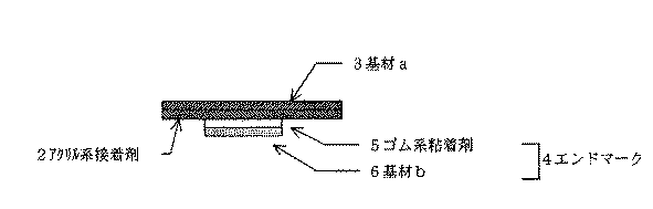
本発明は、基材に塗布されたアクリル系接着剤からなる異方導電材テープにおいて、自動検出のためのエンドマークをアクリル系接着剤上に設けられたゴム系粘着テープとし、エンドマークの厚みとして、ゴム系粘着テープの基材とゴム系粘着剤の総厚みを250μm未満としたものであり、前記アクリル系接着剤が導電粒子を含有する異方導電材テープである。異方導電材テープの基材a(3)に塗布されたアクリル系接着剤(2)を用いた異方導電材テープ(1)において、自動機において異方導電材テープの欠乏を知らせるためセンサーにより感知するエンドマーク(4)としてアクリル系接着剤(2)上にゴム系粘着材(5)と基材b(6)から構成されるゴム系粘着剤テープを設けることにより、異方導電材テープのアクリル系接着剤と相溶することなく、エンドテープの欠落や異方導電材テープの異方導電材の基材背面への転写を防止する事が可能となる。エンドマーク(4)の厚みは、ゴム系粘着テープの基材b(6)とゴム系粘着剤(5)の総厚みが250μm未満、好ましくは100μm以下、より好ましくは、70μm以下とすることにより、異方導電材テープの巻き締まりによる異方導電材とゴム系粘着剤の側面への流失を防ぎ、エンドテープの欠落及び異方導電材テープの異方導電材の基材背面への転写を防止する事が更に向上する。
【0005】
【発明の実施の形態】
本発明を図面を参照しながらさらに具体的に説明する。
図1は本発明の一実施例を説明する断面模式図である。図2、図3は、図1の各部の拡大図である。
本発明の異方導電材テープ(1)は、基材a(3)上に塗布された異方導電性のアクリル系接着剤(2)からなり、高精細化された電子部品の接続に用いられるため無機及び有機物の異物及び汚染を防ぐため、基材aが接着剤の外側となる構造を示している。
本発明に用いられる異方導電材は、被接続体の反り及び伸びを防ぐために接続温度の低温化が可能で、また、接続時のタクトタイムの短時間化が可能である反応性の高いアクリル系接着剤を使用する。
さらに、本発明の異方導電材テープに用いられる基材は、強度及び異方導電材を構成する接着剤の剥離性の面からOPP(延伸ポリプロピレン)、ポリテトラフルオロエチレン、シリコン処理したPET(ポリエチレンテレフタレート)などを用いるが、これらに制限するものではない。
異方導電材を用いた接続は用途及び需要拡大に伴い、オ−トメション化され、異方導電材の欠乏、すなわち異方導電材がなくなっていることを知らせるため、アクリル系接着剤(2)上にエンドマーク(4)を付けて検知するようにしている。このエンドマークは異方導電テープの製造上の作業性から異方導電材の接着剤とは異なる粘着テープが用いられるのが一般的である。
本発明においてアクリル系接着剤(2)の成分が、エンドテープの基材b(6)(一般的には材質としてPETを用いる)上の粘着剤をゴム系粘着剤(5)にすることにより、異方導電材のアクリル系接着剤(2)と相溶せず、エンドテープの欠落や異方導電材テープの異方導電材の基材背面への転写を防止する事が可能である。
【0006】
本発明は、基材a(3)に塗布されたアクリル系接着剤(2)を用いた異方導電材テープ(1)において、自動機において異方導電材テープ(1)の欠乏を知らせるためセンサーにより感知するエンドマーク(4)としてアクリル系接着剤上にゴム系粘着剤テープを設けることにより、異方導電材のアクリル系接着剤と相溶せず、エンドテープの欠落や異方導電材テープの異方導電材の基材背面への転写を防止する事が可能である。
【0007】
【実施例】
次に実施例を説明するが、本発明はこの実施例に限定されるものではない。
(l)異方導電材テープの作製
フイルム形成材としてフェノキシ樹脂(高分子量エポキシ樹脂)50gとアクリル系樹脂であるアクリレート50g、過酸化物を5g添加し、酢酸エチルの30重量%溶液を作製し,これに平均粒径2.5μmのNi粉を5体積%添加した。この溶液を厚み50μmのシリコン処理したポリエチレンテレフタレートフィルム基材にロールコータで塗布し、110℃、20分乾燥し、厚み50μmの異方導電材フィルムを得た。さらに、このフィルムを幅5mmにスリットして、長さ50mの異方導電材テープを得た。
(2)評価
試験として2枚のスライドガラスの間に2枚の異方導電材フィルムをテープに巻かれた状態となる構成で挟み、2枚の異方導電材フィルムの間に表1に示す各種の粘着剤系のテープをエンドテープとして挟み1Kgの荷重をかけ、23℃で10日間放置し、エンドテープの欠落や異方導電材テープの異方導電材の基材背面への転写を総合評価した。この時の試験片のサイズは10×73mmとした。更に、実際にテープ長50mの異方導電材テープを用いて、23℃、10日間放置して評価した。その結果、エンドテープの欠落や異方導電材テープの異方導電材の基材背面への転写があったものは×で、ないものは○で示した。
評価結果を表1に示した。
【0008】
【表1】
実施例1のNo.31Eをエンドマークとして使用した場合、試験においてエンドテープの粘着剤及びアクリル系接着剤のハミダシは観察されなかった。また、実際のテープにおいても側面にハミダシはなく、テープを引き出した時、エンドテープの欠落及び異方導電材テープの異方導電材の基材背面への転写はなかった。
一方、比較例1においては、実施例1と同様の評価を行ったが、異方導電材の接着剤とエンドテープの粘着剤が相溶し、試験においてハミダシが観察され、実際のテープにおいても側面にハミダシが発生し、テープを引き出した時、エンドテープの欠落及び異方導電材の異方導電材の基材背面への転写が起こった。
実施例2〜3においても実施例1同様に評価した所良好な結果が得られた。
比較例2においては、比較例1と同様はみ出しが観察された。比較例3においては、エンドテープの厚みが厚いため、比較例1と同様はみ出しが観察された。
【0010】
【発明の効果】
本発明によれば、異方導電材の接着剤としてアクリル系接着剤を使用した場合に、自動検出のためのエンドマークをゴム系粘着テープとする異方導電材テープ構成にすることにより、エンドテープの欠落や異方導電材テープの異方導電材が基材背面への転写を防止することができる。
【図面の簡単な説明】
【図1】 本発明の異方導電材テープの全体構成を示す断面模式図。
【図2】 本発明の異方導電材テープの一部分を示す断面模式図。
【図3】 本発明の異方導電材テープのエンドテープ部分を示す断面模式図。
【符号の説明】
1.異方導電材テープ
2.アクリル系接着剤
3.基材a
4.エンドマーク
5.ゴム系粘着剤
6.基材b[0001]
BACKGROUND OF THE INVENTION
The present invention relates to, for example, an anisotropic conductive material tape for bonding and fixing an electronic component such as a liquid crystal panel, a PDP panel, an EL panel, and a pair chip mounting, a circuit board, and circuit boards, and electrically connecting both electrodes. In particular, the present invention relates to an end mark for automatic detection provided in the vicinity of a winding core portion of an anisotropic conductive material wound on a reel.
[0002]
[Prior art]
As a connecting method using an anisotropic conductive material tape, an anisotropic conductive member, which is a film-like adhesive, is sandwiched between opposed electrodes and connected by heating and pressing. Conductive particles for obtaining electrical connection between electrodes are mixed in the film-like adhesive, and as the resin, a thermoplastic resin, a thermosetting resin, or a mixed system of a thermoplastic resin and a thermosetting resin is used. (See, for example, JP-A-55-104007).
Also known is a circuit connection method that does not contain conductive particles and is made only of a resin (for example, JP-A-60-262430).
Typical examples of the resin include a styrene resin system and a polyester resin system as thermoplastic resin systems, and an epoxy resin system and a silicone resin system are known as thermosetting resin systems. Heating and pressing are necessary to connect both the thermoplastic resin system and the thermosetting resin system. This is because the thermoplastic resin system allows the resin to flow to obtain adhesion to the adherend, and the thermosetting resin system further performs a resin curing reaction. In recent years, from the viewpoint of connection reliability, a mixed system of a thermoplastic resin and a thermosetting resin and a thermosetting resin system have become mainstream.
In recent years, in order to prevent warpage and elongation of the connected body, it has been required to lower the connection temperature at the time of connecting the anisotropic conductive material, and the use of the anisotropic conductive material has been expanded, and liquid crystal panels and PDP panels. With increasing demand for EL panels, bare chip mounting, etc., there is a strong demand for shortening the tact time at the time of connection.
Recently, a highly reactive thermal radical system that can be connected at a lower temperature and in a shorter time than the epoxy resin system and the silicone resin system, which are the thermosetting resin systems, has attracted attention. This thermal radical system is mainly composed of an acrylic adhesive.
On the other hand, the connection of anisotropic conductive materials is generally automated with increasing applications and demand. For this reason, the anisotropic conductive material is in the form of a tape, and an adhesive tape with a different color from the adhesive is applied as an end tape on the adhesive near the core of the reel, and the automatic machine detects this end tape with a sensor. However, the shortage of anisotropic conductive material tape is informed, and the supply is performed without flaws.
In the prior art, as described above, anisotropic conductive materials include styrene resin and polyester resin as thermoplastic resins, and epoxy resin and silicone resin as thermosetting resins. Acrylic adhesive was used for the tape. However, the thermal adhesive acrylic adhesive is compatible with the end adhesive acrylic adhesive, which is the same adhesive system, causing sticking of adhesive or anisotropic conductive material to the side of the reel. This causes inconvenience that the end tape is missing or the anisotropic conductive material of the anisotropic conductive material tape is transferred to the back surface of the substrate.
[0003]
[Problems to be solved by the invention]
The present invention has been made in view of the above-described drawbacks, and has an object of preventing the end tape from being lost and the anisotropic conductive material of the anisotropic conductive material tape from being transferred to the back surface of the base material.
[0004]
[Means for Solving the Problems]
The present invention relates to an anisotropic conductive material tape comprising an acrylic adhesive applied to a base material, wherein the end mark for automatic detection is a rubber-based adhesive tape provided on the acrylic adhesive, and the thickness of the end mark As described above, the total thickness of the base of the rubber-based adhesive tape and the rubber-based adhesive is less than 250 μm , and the acrylic adhesive is an anisotropic conductive material tape containing conductive particles . Sensor for notifying the lack of anisotropic conductive material tape in an automatic machine in anisotropic conductive material tape (1) using acrylic adhesive (2) applied to base material a (3) of anisotropic conductive material tape By providing a rubber adhesive tape composed of a rubber adhesive (5) and a base material b (6) on an acrylic adhesive (2) as an end mark (4) to be detected by the anisotropic conductive material Without being compatible with the acrylic adhesive of the tape, it is possible to prevent the end tape from being lost or the anisotropic conductive material of the anisotropic conductive material tape from being transferred to the back surface of the base material. The thickness of the end mark (4) is such that the total thickness of the base material b (6) of the rubber-based adhesive tape and the rubber-based adhesive (5) is less than 250 μm, preferably 100 μm or less, more preferably 70 μm or less. , Prevents the anisotropic conductive material and rubber adhesive from flowing out to the side due to the tightness of the anisotropic conductive material tape, and transfers the anisotropic conductive material of the anisotropic conductive material to the back of the substrate. The prevention is further improved.
[0005]
DETAILED DESCRIPTION OF THE INVENTION
The present invention will be described more specifically with reference to the drawings.
FIG. 1 is a schematic sectional view for explaining one embodiment of the present invention. 2 and 3 are enlarged views of each part of FIG.
The anisotropic conductive material tape (1) of the present invention comprises an anisotropic conductive acrylic adhesive (2) applied on a base material a (3), and is used for connecting high-definition electronic components. Therefore, in order to prevent foreign matter and contamination of inorganic and organic substances, the structure in which the substrate a is outside the adhesive is shown.
The anisotropic conductive material used in the present invention is a highly reactive acrylic that can reduce the connection temperature to prevent warpage and elongation of the connected body, and can shorten the tact time at the time of connection. Use adhesives.
Furthermore, the base material used for the anisotropic conductive material tape of the present invention is OPP (stretched polypropylene), polytetrafluoroethylene, silicon treated PET (from the viewpoint of strength and peelability of the adhesive constituting the anisotropic conductive material ( Polyethylene terephthalate) or the like is used, but is not limited thereto.
Acrylic adhesives (2) are used to inform the fact that anisotropic conductive materials are lacking, that is, anisotropic conductive materials are lost, as anisotropic conductive materials are used in connection with expanding applications and demand. An end mark (4) is attached on the top to detect. As the end mark, a pressure-sensitive adhesive tape different from the anisotropic conductive material adhesive is generally used because of the workability in manufacturing the anisotropic conductive tape.
In the present invention, the component of the acrylic adhesive (2) is obtained by changing the adhesive on the base material b (6) of the end tape (generally using PET as a material) to the rubber adhesive (5). In addition, it is incompatible with the acrylic adhesive (2) of the anisotropic conductive material, and it is possible to prevent the end tape from being lost or transferring the anisotropic conductive material of the anisotropic conductive material tape to the back surface of the base material.
[0006]
In the present invention, the anisotropic conductive material tape (1) using the acrylic adhesive (2) applied to the base material a (3) is used to inform the lack of the anisotropic conductive material tape (1) in an automatic machine. By providing a rubber adhesive tape on the acrylic adhesive as an end mark (4) that is detected by the sensor, it will not be compatible with the acrylic adhesive of the anisotropic conductive material. It is possible to prevent the anisotropic conductive material of the tape from being transferred to the back surface of the base material.
[0007]
【Example】
Next, although an Example is described, this invention is not limited to this Example.
(L) Preparation of anisotropic conductive material tape 50 g of phenoxy resin (high molecular weight epoxy resin), 50 g of acrylic resin acrylate and 5 g of peroxide were added as a film forming material to prepare a 30 wt% solution of ethyl acetate. , 5% by volume of Ni powder having an average particle size of 2.5 μm was added thereto. This solution was applied to a silicon-treated polyethylene terephthalate film substrate having a thickness of 50 μm with a roll coater and dried at 110 ° C. for 20 minutes to obtain an anisotropic conductive material film having a thickness of 50 μm. Further, this film was slit to a width of 5 mm to obtain an anisotropic conductive material tape having a length of 50 m.
(2) As an evaluation test, two anisotropic conductive material films are sandwiched between two slide glasses in a state of being wound on a tape, and are shown in Table 1 between the two anisotropic conductive material films. Put various adhesive tapes as end tapes, apply 1kg load and leave them at 23 ° C for 10 days to comprehensively remove end tapes and transfer anisotropic conductive materials to the back of the base material. evaluated. The size of the test piece at this time was 10 × 73 mm. Further, an anisotropic conductive material tape having a tape length of 50 m was actually used for evaluation at 23 ° C. for 10 days. As a result, when the end tape was missing or when the anisotropic conductive material of the anisotropic conductive material tape was transferred to the back surface of the base material, the result was indicated by x, and when it was not, the result was indicated by ◯.
The evaluation results are shown in Table 1.
[0008]
[Table 1]
No. of Example 1 When 31E was used as an end mark, no end tape adhesive or acrylic adhesive was observed in the test. Further, even in an actual tape, there was no stagnation on the side surface, and when the tape was pulled out, there was no end tape missing and no transfer of the anisotropic conductive material of the anisotropic conductive material tape to the back surface of the base material.
On the other hand, in Comparative Example 1, the same evaluation as in Example 1 was performed, but the adhesive of the anisotropic conductive material and the pressure sensitive adhesive of the end tape were compatible, and stagnation was observed in the test. When the tape was pulled out, the end tape was missing and the anisotropic conductive material was transferred to the back surface of the anisotropic conductive material.
In Examples 2 to 3, good results were obtained when evaluated in the same manner as in Example 1.
In Comparative Example 2, the protrusion was observed as in Comparative Example 1. In Comparative Example 3, since the end tape was thick, the protrusion was observed as in Comparative Example 1.
[0010]
【The invention's effect】
According to the present invention, when an acrylic adhesive is used as the anisotropic conductive material adhesive, the end of the end mark for automatic detection is configured as an anisotropic conductive material tape with a rubber-based adhesive tape. The lack of the tape or the anisotropic conductive material of the anisotropic conductive material tape can prevent transfer to the back surface of the base material.
[Brief description of the drawings]
FIG. 1 is a schematic cross-sectional view showing the overall configuration of an anisotropic conductive material tape of the present invention.
FIG. 2 is a schematic cross-sectional view showing a part of the anisotropic conductive material tape of the present invention.
FIG. 3 is a schematic cross-sectional view showing an end tape portion of the anisotropic conductive material tape of the present invention.
[Explanation of symbols]
1. 1. Anisotropic conductive material tape 2. Acrylic adhesive Base material a
4). End mark 5. Rubber adhesive 6. Base material b
Claims (7)
Priority Applications (1)
| Application Number | Priority Date | Filing Date | Title |
|---|---|---|---|
| JP2000092976A JP4465788B2 (en) | 2000-03-28 | 2000-03-28 | Anisotropic conductive tape and reel |
Applications Claiming Priority (1)
| Application Number | Priority Date | Filing Date | Title |
|---|---|---|---|
| JP2000092976A JP4465788B2 (en) | 2000-03-28 | 2000-03-28 | Anisotropic conductive tape and reel |
Related Child Applications (1)
| Application Number | Title | Priority Date | Filing Date |
|---|---|---|---|
| JP2009193236A Division JP4844661B2 (en) | 2009-08-24 | 2009-08-24 | Anisotropic conductive tape |
Publications (2)
| Publication Number | Publication Date |
|---|---|
| JP2001284005A JP2001284005A (en) | 2001-10-12 |
| JP4465788B2 true JP4465788B2 (en) | 2010-05-19 |
Family
ID=18608229
Family Applications (1)
| Application Number | Title | Priority Date | Filing Date |
|---|---|---|---|
| JP2000092976A Expired - Fee Related JP4465788B2 (en) | 2000-03-28 | 2000-03-28 | Anisotropic conductive tape and reel |
Country Status (1)
| Country | Link |
|---|---|
| JP (1) | JP4465788B2 (en) |
Cited By (1)
| Publication number | Priority date | Publication date | Assignee | Title |
|---|---|---|---|---|
| CN102514986A (en) * | 2005-08-31 | 2012-06-27 | 日立化成工业株式会社 | Adhesive reel |
Families Citing this family (25)
| Publication number | Priority date | Publication date | Assignee | Title |
|---|---|---|---|---|
| JP4608839B2 (en) * | 2002-12-24 | 2011-01-12 | 日立化成工業株式会社 | Adhesive tape reel and bonding apparatus |
| JP2004331833A (en) * | 2003-05-08 | 2004-11-25 | Hitachi Chem Co Ltd | Tape reel for adhesive materials |
| TW200913827A (en) * | 2002-07-30 | 2009-03-16 | Hitachi Chemical Co Ltd | Adhesive material reel |
| JP2005330296A (en) * | 2003-06-20 | 2005-12-02 | Hitachi Chem Co Ltd | Connecting method of adhesive material tape |
| JP2004211017A (en) * | 2003-01-08 | 2004-07-29 | Hitachi Chem Co Ltd | Adhesive tape, method of producing the same and compression adhesion method for the same |
| JP2004059776A (en) * | 2002-07-30 | 2004-02-26 | Hitachi Chem Co Ltd | Anisotropic conductive material tape |
| JP2004210524A (en) * | 2003-01-08 | 2004-07-29 | Hitachi Chem Co Ltd | Bonding device |
| CN101920862B (en) * | 2002-07-30 | 2012-05-02 | 日立化成工业株式会社 | Crimping connection method of adhesive tapes |
| CN101920863B (en) * | 2002-07-30 | 2011-12-07 | 日立化成工业株式会社 | Method for producing adhesive materials for tapes composed with the same |
| JP2004203944A (en) * | 2002-12-24 | 2004-07-22 | Hitachi Chem Co Ltd | Method for connecting adhesive tapes to each other and adhesion apparatus |
| JP4639988B2 (en) * | 2005-06-23 | 2011-02-23 | 日立化成工業株式会社 | Resin film for end mark and adhesive tape with end mark |
| KR20100117680A (en) * | 2005-08-04 | 2010-11-03 | 히다치 가세고교 가부시끼가이샤 | Anisotropic conductive film and method for producing same |
| KR100791167B1 (en) | 2006-01-09 | 2008-01-02 | 엘에스전선 주식회사 | roll type anisotropic conductive film |
| EP2017315A4 (en) | 2006-04-24 | 2011-05-25 | Hitachi Chemical Co Ltd | Adhesive tape |
| US20100167030A1 (en) * | 2006-10-31 | 2010-07-01 | Hitachi Chemical Company, Ltd. | Adhesive tape and adhesive tape roll |
| JP2009138203A (en) * | 2009-01-13 | 2009-06-25 | Hitachi Chem Co Ltd | Anisotropic conductive material tape |
| CN102037615B (en) * | 2009-02-27 | 2013-08-28 | 日立化成株式会社 | Adhesive material reel |
| CN102037614B (en) * | 2009-03-26 | 2014-03-19 | 日立化成株式会社 | Adhesive material reel |
| JP4692664B2 (en) * | 2009-05-13 | 2011-06-01 | 日立化成工業株式会社 | Adhesive tape crimping method |
| WO2013024544A1 (en) * | 2011-08-18 | 2013-02-21 | 日立化成工業株式会社 | Adhesive material reel |
| WO2016136946A1 (en) | 2015-02-27 | 2016-09-01 | デクセリアルズ株式会社 | Reel body, film connection body, film winding body, and manufacturing method for film connection body |
| JP7119288B2 (en) * | 2016-05-05 | 2022-08-17 | デクセリアルズ株式会社 | filler placement film |
| KR102534610B1 (en) * | 2017-09-29 | 2023-05-19 | 가부시끼가이샤 레조낙 | Adhesive tape, adhesive tape winding reel, and manufacturing method of adhesive tape |
| WO2019151434A1 (en) | 2018-02-01 | 2019-08-08 | 日立化成株式会社 | Member connection method and adhesive tape |
| KR20240015631A (en) * | 2021-06-02 | 2024-02-05 | 가부시끼가이샤 레조낙 | Adhesive Tape and Adhesive Tape Winding Reel |
Family Cites Families (14)
| Publication number | Priority date | Publication date | Assignee | Title |
|---|---|---|---|---|
| JPS55104007A (en) * | 1979-02-01 | 1980-08-09 | Kokoku Rubber Ind | Adhesive anisotripic conductive substance and shorting member using same |
| JPS6134082A (en) * | 1984-07-26 | 1986-02-18 | Okura Ind Co Ltd | Lowly odorous two-pack acrylic adhesive having excellent adhesion |
| JPH058567A (en) * | 1991-07-02 | 1993-01-19 | Dainippon Printing Co Ltd | Self-adhesive tape for end mark |
| JPH05155168A (en) * | 1991-12-10 | 1993-06-22 | Ricoh Co Ltd | Roll paper |
| JPH07126582A (en) * | 1993-10-29 | 1995-05-16 | Minnesota Mining & Mfg Co <3M> | Pressure-sensitive adhesive tape having fine shape on surface of pressure-sensitive adhesive, such tape for lengthmeasurement and their production |
| JPH084744A (en) * | 1994-06-20 | 1996-01-09 | Minnesota Mining & Mfg Co <3M> | Fixture for cord |
| JP3060850B2 (en) * | 1994-09-30 | 2000-07-10 | 松下電器産業株式会社 | Crimping method of anisotropic conductive tape |
| JPH08290873A (en) * | 1995-04-21 | 1996-11-05 | Dainippon Printing Co Ltd | Web winding roll |
| JPH09153516A (en) * | 1995-11-30 | 1997-06-10 | Sumitomo Bakelite Co Ltd | Semiconductor device and ic chip inspecting method |
| JP3034282U (en) * | 1996-08-01 | 1997-02-14 | 信越ポリマー株式会社 | Heat seal connector |
| JP3152286B2 (en) * | 1997-07-01 | 2001-04-03 | 住友金属工業株式会社 | Buffer material for coil end mark prevention and coil winding method |
| JPH11148059A (en) * | 1997-09-11 | 1999-06-02 | Hitachi Chem Co Ltd | Adhesive and electronic parts |
| JPH11339575A (en) * | 1998-05-22 | 1999-12-10 | Sony Corp | Manufacture of anisotropic conductive tape and its manufacturing device |
| JP2000011760A (en) * | 1998-06-29 | 2000-01-14 | Kyoritsu Kagaku Sangyo Kk | Anisotropic conductive composition and manufacture of anisotropic conductive member using it |
-
2000
- 2000-03-28 JP JP2000092976A patent/JP4465788B2/en not_active Expired - Fee Related
Cited By (2)
| Publication number | Priority date | Publication date | Assignee | Title |
|---|---|---|---|---|
| CN102514986A (en) * | 2005-08-31 | 2012-06-27 | 日立化成工业株式会社 | Adhesive reel |
| CN102514986B (en) * | 2005-08-31 | 2016-04-27 | 日立化成株式会社 | Felting agent coil |
Also Published As
| Publication number | Publication date |
|---|---|
| JP2001284005A (en) | 2001-10-12 |
Similar Documents
| Publication | Publication Date | Title |
|---|---|---|
| JP4465788B2 (en) | Anisotropic conductive tape and reel | |
| CN102951498B (en) | Adhesives reel and reel external member | |
| JP2004059776A (en) | Anisotropic conductive material tape | |
| CN101683934B (en) | Reel for adhesive | |
| WO2010110094A1 (en) | Adhesive material reel | |
| WO2010098354A1 (en) | Adhesive material reel | |
| JP2008156126A (en) | Method and body for connecting adhesive tape | |
| JP5928567B2 (en) | Adhesive reel | |
| JP2007224111A (en) | Anisotropic conductive adhesive sheet and its production method | |
| JP4147614B2 (en) | Rolled body having an adhesive layer | |
| JP3503735B2 (en) | Anisotropic conductive adhesive film roll | |
| JP4844661B2 (en) | Anisotropic conductive tape | |
| JP4239585B2 (en) | Adhesive tape connection method and adhesive tape connector | |
| JP2004202738A5 (en) | ||
| JP3712334B2 (en) | Anisotropic conductive adhesive film | |
| TWI480221B (en) | Circuit connecting tape, adhesive reel and method for manufacturing circuit-connected body | |
| JP4835548B2 (en) | Rolled body having an adhesive layer | |
| JP2012077305A (en) | Film for anisotropically conductive connection and reel body | |
| JP4639988B2 (en) | Resin film for end mark and adhesive tape with end mark | |
| JP4941217B2 (en) | Rolled body having an adhesive layer | |
| JP2007224112A (en) | Anisotropic conductive adhesive sheet and method for producing the same | |
| JP2003017822A (en) | Protective film, resin conductor foil laminate attached with, protective film and method of manufacturing flexible printed wiring board using the same | |
| JP2002324432A (en) | Anisotropic conductive tape | |
| JP2008069357A (en) | Winding having adhesive layer |
Legal Events
| Date | Code | Title | Description |
|---|---|---|---|
| A621 | Written request for application examination |
Free format text: JAPANESE INTERMEDIATE CODE: A621 Effective date: 20070131 |
|
| RD03 | Notification of appointment of power of attorney |
Free format text: JAPANESE INTERMEDIATE CODE: A7423 Effective date: 20071213 |
|
| A977 | Report on retrieval |
Free format text: JAPANESE INTERMEDIATE CODE: A971007 Effective date: 20090206 |
|
| A131 | Notification of reasons for refusal |
Free format text: JAPANESE INTERMEDIATE CODE: A131 Effective date: 20090217 |
|
| A521 | Request for written amendment filed |
Free format text: JAPANESE INTERMEDIATE CODE: A523 Effective date: 20090420 |
|
| A131 | Notification of reasons for refusal |
Free format text: JAPANESE INTERMEDIATE CODE: A131 Effective date: 20090623 |
|
| A521 | Request for written amendment filed |
Free format text: JAPANESE INTERMEDIATE CODE: A523 Effective date: 20090824 |
|
| A131 | Notification of reasons for refusal |
Free format text: JAPANESE INTERMEDIATE CODE: A131 Effective date: 20090929 |
|
| TRDD | Decision of grant or rejection written | ||
| A01 | Written decision to grant a patent or to grant a registration (utility model) |
Free format text: JAPANESE INTERMEDIATE CODE: A01 Effective date: 20100202 |
|
| A01 | Written decision to grant a patent or to grant a registration (utility model) |
Free format text: JAPANESE INTERMEDIATE CODE: A01 |
|
| A61 | First payment of annual fees (during grant procedure) |
Free format text: JAPANESE INTERMEDIATE CODE: A61 Effective date: 20100215 |
|
| FPAY | Renewal fee payment (event date is renewal date of database) |
Free format text: PAYMENT UNTIL: 20130305 Year of fee payment: 3 |
|
| FPAY | Renewal fee payment (event date is renewal date of database) |
Free format text: PAYMENT UNTIL: 20130305 Year of fee payment: 3 |
|
| FPAY | Renewal fee payment (event date is renewal date of database) |
Free format text: PAYMENT UNTIL: 20140305 Year of fee payment: 4 |
|
| S531 | Written request for registration of change of domicile |
Free format text: JAPANESE INTERMEDIATE CODE: R313531 |
|
| S533 | Written request for registration of change of name |
Free format text: JAPANESE INTERMEDIATE CODE: R313533 |
|
| FPAY | Renewal fee payment (event date is renewal date of database) |
Free format text: PAYMENT UNTIL: 20140305 Year of fee payment: 4 |
|
| R350 | Written notification of registration of transfer |
Free format text: JAPANESE INTERMEDIATE CODE: R350 |
|
| LAPS | Cancellation because of no payment of annual fees |