JP4433834B2 - Toroidal continuously variable transmission - Google Patents
Toroidal continuously variable transmission Download PDFInfo
- Publication number
- JP4433834B2 JP4433834B2 JP2004063583A JP2004063583A JP4433834B2 JP 4433834 B2 JP4433834 B2 JP 4433834B2 JP 2004063583 A JP2004063583 A JP 2004063583A JP 2004063583 A JP2004063583 A JP 2004063583A JP 4433834 B2 JP4433834 B2 JP 4433834B2
- Authority
- JP
- Japan
- Prior art keywords
- trunnion
- continuously variable
- variable transmission
- power roller
- lubricating oil
- Prior art date
- Legal status (The legal status is an assumption and is not a legal conclusion. Google has not performed a legal analysis and makes no representation as to the accuracy of the status listed.)
- Expired - Fee Related
Links
Images


Classifications
-
- F—MECHANICAL ENGINEERING; LIGHTING; HEATING; WEAPONS; BLASTING
- F16—ENGINEERING ELEMENTS AND UNITS; GENERAL MEASURES FOR PRODUCING AND MAINTAINING EFFECTIVE FUNCTIONING OF MACHINES OR INSTALLATIONS; THERMAL INSULATION IN GENERAL
- F16H—GEARING
- F16H57/00—General details of gearing
- F16H57/04—Features relating to lubrication or cooling or heating
- F16H57/048—Type of gearings to be lubricated, cooled or heated
- F16H57/0487—Friction gearings
- F16H57/049—Friction gearings of the toroid type
Description
本発明は、自動車用或いは各種産業機械用の変速機構として利用されるトロイダル型無段変速機に関する。 The present invention relates to a toroidal continuously variable transmission used as a transmission mechanism for automobiles or various industrial machines.
従来、自動車等の車両に用いられる無段変速機として、図4及び図5に示されるようなトロイダル型無段変速機10が知られている。トロイダル型無段変速機10では、エンジン等の駆動源と連動して回転する入力軸11の周囲に、入力ディスク12と出力ディスク13がニードルローラ軸受14を介して互いに同心に、且つ互いに独立して回転自在に支持されている。
Conventionally, a toroidal continuously
入力ディスク12の背面側には、カムディスク15が入力軸11に対してスプライン係合されている。また、カムディスク15と入力ディスク12との間には複数のローラ16が介在されており、入力ディスク12を出力ディスク13側に押し付けるローディングカム式の押圧機構17を構成している。出力ディスク13はキー18を介して出力歯車19と係合しており、出力ディスク13と出力歯車19とは同期して回転する。
A
また、入力ディスク12と出力ディスク13との間には、入力軸11に対して捻れの位置にある一対の傾転軸21、22を中心として揺動する一対のトラニオン20が設けられている。各トラニオン20は、図5に示されるように、一対の傾転軸21,22と、中央部の内平面24に円孔25が開口した本体部23とを有する。また、本体部23は、両端部において、内平面側に折り曲げられて一対の傾転軸21,22と連結する一対の折れ曲がり部26,26を有している。
Further, between the
トラニオン20の本体部23の円孔25には、変位軸27がニードルローラ軸受28を介して揺動自在に設けられている。変位軸27は、トラニオン20に支持される支持軸部27aと、支持軸部27aと平行で且つ偏心した枢支軸部27bとからなり、枢支軸部27bの周囲にはパワーローラ29がニードルローラ軸受30を介して回転自在に支持されている。パワーローラ29の外周面は、円弧形状の凹断面に形成された入力ディスク12及び出力ディスク13の各内側面12a、13aと当接する球状凸面に形成されたトロイダル面29aを備えており、入力ディスク12と出力ディスク13との間に傾転自在に転接されている。
A
また、トラニオン20の本体部23の内平面24とパワーローラ29の外側面との間には、パワーローラ29の外側面から順に、スラスト転がり軸受であるパワーローラ軸受部31と、スラストニードル軸受32が設けられている。パワーローラ軸受部31はパワーローラ29に加わるスラスト方向の荷重を支承しつつ、パワーローラ29の回転を許容するものである。このようなスラスト玉軸受31の複数の玉33は、トラニオン20側に設けられた円環状の外輪34と回転部としてのパワーローラ29との両転動面間に配置され、円環状の保持器35によって保持されている。
Further, between the
トラニオン20の両端の傾転軸21、22はニードルローラ軸受36,36を介して一対の支持板37,37に対して揺動自在および軸方向に変位自在に支持されており、トラニオン20の揺動により、変位軸27の傾斜角度を調節自在としている。なお、一対の支持板37,37は、トロイダル型無段変速機を収容するケーシング(図示せず)に設けられた支持ポスト(図示せず)に変位自在に配置されている。
The tilting
また、各トラニオン20の一方の傾転軸21には、駆動ロッド38(以下、トラニオン軸と称す。)が一体化されており、このトラニオン軸38の中間部外周面には駆動ピストン39が設けられている。そして、この駆動ピストン39は、ケーシングに固定されたバルブボディ40,41によって形成された駆動シリンダ42内に油密に嵌挿されている。
A drive rod 38 (hereinafter referred to as a trunnion shaft) is integrated with one
さらに、トラニオン20の一方の傾転軸21と一体化されたトラニオン軸38には、駆動ピストン39とともに、間座43を介して安全ケーブル用のプーリ44が外嵌されており、これら駆動ピストン39、間座43及びプーリ44は、ナット45を利用して駆動ロッド38に締め付け固定されている。特に、駆動ピストン39とプーリ44は、キー溝、二平面、スプライン嵌合等を用いて、トラニオン20と一体回転するように回り止めされている。
Further, a
前述のように構成されたトロイダル型無段変速機10によれば、エンジン等の駆動源から押圧装置17のカムディスク15に伝達された回転は、ローラ16を介して入力ディスク12に伝達される。入力ディスク12の回転はパワーローラ29を介して出力ディスク13に伝達され、出力ディスク13の回転が出力歯車19より取り出される。
According to the toroidal type continuously
入力側と出力側との間の回転速度比を変える場合には、一対のトラニオン20の各駆動ピストン39を互いに逆方向に変位させる。各駆動ピストン39の変位に伴って各トラニオン20がそれぞれ逆方向に変位する。その結果、各パワーローラ29のトロイダル面29aと入力ディスク12及び出力ディスク13の内側面12a,13aとの当接部に作用する接線方向の力の向きが変化し、この力の向きの変化に伴ってトラニオン20が支持板37,37に枢支された一対の傾転軸21、22を中心として互いに逆方向に揺動する。
When changing the rotational speed ratio between the input side and the output side, the
このように構成されるトロイダル型無段変速機10では、パワーローラ29は入力ディスク12及び出力ディスク13に挟まれて動力を伝達しており、過大なスラスト荷重を受ける。そして、パワーローラ29にかかるスラスト荷重は、パワーローラ軸受部31やスラストニードル軸受32で支承される。特に、パワーローラ軸受部31は、過大なスラスト力を受けて高速で回転するので、この部分に潤滑油を供給することは重要である。
In the toroidal type continuously
従来、これらパワーローラ軸受部31やスラストニードル軸受32への潤滑油の給油方法が種々提案されている(例えば、特許文献1〜5参照。)。図6に示される従来の給油方法では、トラニオン軸38にドリル加工を施して、トラニオン軸38内にその軸方向に沿って小径のトラニオン軸縦孔50を形成し、更に、トラニオン軸38の径方向に沿って、トラニオン軸縦孔50と連通するトラニオン軸横孔51が形成されている。また、トラニオン20の本体部23には、円孔25を貫通する軸方向に沿った小径の本体部縦孔52と、本体部縦孔52を通過して円孔25の内周面に形成されたリング溝53と、この本体部縦孔52の端部から内平面24に向かって延びる本体部横孔54とトラニオン軸縦孔50と本体部縦孔52とを連通する本体部斜め孔55とが形成されている。トラニオン軸縦孔50、本体部縦孔52、及び本体部斜め孔55の各加工端部には、プラグ56,57,58がそれぞれ圧入されている。なお、図6のX方向は実車取り付け状態における上下方向を表し、Y方向は水平方向を表す。
Conventionally, various methods of supplying lubricating oil to the power roller bearing
そして、バルブボディ40に形成された油路40aからの潤滑油が、駆動ピストン39のスリーブ部39aに形成された給油孔59を介して、トラニオン20に供給され、図6の矢印に沿って、トラニオン軸横孔51、トラニオン軸縦孔50、本体部斜め孔55、本体部縦孔52、リング溝53、本体部横孔54を通過して、変位軸27に形成されたオイルキャッチ部60に供給される。その後、潤滑油は、オイルキャッチ部60からピボット縦孔61とピボット横孔62に分岐され、パワーローラ軸受部31は、ピボット縦孔61から供給された潤滑油と、ピボット横孔62からニードルローラ軸受30の隙間を介して供給された潤滑油とにより潤滑される。
Then, the lubricating oil from the
また、特許文献1に記載のトロイダル型無段変速機では、駆動シリンダからの潤滑油がトラニオン軸の外周面を通過し、トラニオンの本体部に形成された本体部斜め孔、本体部横孔、本体部縦孔に導かれる経路とした給油方法が知られている。さらに、特許文献3に記載のトロイダル型無段変速機では、トラニオンの本体部に、本体部縦孔や本体部横孔を設けずに、トラニオンの本体部斜め孔からパワーローラ前方に潤滑用部材を設けて、パワーローラと入力ディスク及び出力ディスクとの接触部を潤滑している。
ところで、トラニオンは強度確保のため、硬度がHRC30程度とされている。このため、図6や特許文献1に記載のトロイダル型無段変速機では、トラニオン軸に形成されたトラニオン軸縦孔やトラニオン軸横孔、また、トラニオンの本体部に形成された本体部縦孔、本体部横孔、本体部斜め孔等、これら深孔を加工するためには、加工時間が長くなり、また、ドリル等の孔空け工具の摩耗が早く、工具費用が高くなるという問題がある。 By the way, the trunnion has a hardness of about HRC30 in order to ensure strength. Therefore, in the toroidal continuously variable transmission described in FIG. 6 and Patent Document 1, a trunnion shaft vertical hole and a trunnion shaft horizontal hole formed in the trunnion shaft, and a main body vertical hole formed in the main body portion of the trunnion In order to machine these deep holes, such as the body part horizontal hole and the body part oblique hole, there is a problem that the machining time becomes long, and the drilling tool such as a drill wears quickly and the tool cost becomes high. .
また、複数の孔を交差させて潤滑経路を形成することから、交差部分にバリが生じ、バリ取りの作業コストが嵩んだり、潤滑経路の内部をクリーンに保つため、高圧洗浄等の特別な洗浄を行なう必要があった。さらに、トラニオンには、高いスラスト力が入力されるため、孔が多い場合やその孔の位置によっては、応力集中により強度が低下するという問題がある。 In addition, since the lubrication path is formed by intersecting a plurality of holes, burrs are generated at the intersections, and the work cost of deburring increases, and the interior of the lubrication path is kept clean. It was necessary to perform washing. Furthermore, since a high thrust force is input to the trunnion, there is a problem that the strength decreases due to stress concentration when there are many holes or depending on the positions of the holes.
また、特許文献3に記載のトロイダル型無段変速機は、パワーローラ前方に潤滑用部材を設けており、本体部の折れ曲がり部に潤滑孔を形成する必要があり、本体部の強度をさらに改善する余地があった。 Further, the toroidal continuously variable transmission described in Patent Document 3 is provided with a lubricating member in front of the power roller, and it is necessary to form a lubrication hole in the bent portion of the main body, further improving the strength of the main body. There was room to do.
本発明は、上記の問題点を鑑み、トラニオンの潤滑孔の数及び潤滑孔の交差部分を削減し、孔加工時間の短縮および交差部分のバリ取り工程を低減して、加工コストを低減するとともに、トラニオン潤滑孔での応力集中を緩和して強度低下の防止を図ったトロイダル型無段変速機を提供することを目的とする。 In view of the above-described problems, the present invention reduces the number of lubrication holes of the trunnion and the intersection of the lubrication holes, shortens the drilling time and reduces the deburring process of the intersection, and reduces the machining cost. Another object of the present invention is to provide a toroidal continuously variable transmission that mitigates stress concentration in trunnion lubrication holes and prevents strength reduction.
本発明の上記目的は、以下の構成によって達成される。
(1) 互いに同心に、且つ互いに独立して回転自在に支持された入力ディスク及び出力ディスクと、
前記入力ディスクと前記出力ディスクとの間に傾転自在に転接するパワーローラと、
内平面と背面とを有する本体部と該本体部の両側に形成された一対の傾転軸とを備え、前記パワーローラを回転自在に支持しつつ、前記一対の傾転軸周りに傾転可能なトラニオンと、
前記パワーローラの回転を許容しつつ、前記パワーローラのスラスト荷重を支承するパワーローラ軸受部と、
を備えたトロイダル型無段変速機であって、
前記トラニオンの前記背面には、前記パワーローラ軸受部に潤滑油を供給するため、前記トラニオンと同期して傾転する潤滑油供給部材が接続されており、
前記潤滑油供給部材は、前記トラニオンを揺動自在且つ軸方向に変位自在に支持する支持板を跨いで、前記トラニオンの前記背面に接続されていることを特徴とするトロイダル型無段変速機。
(2) 前記トラニオンには、前記背面から前記内平面に貫通する潤滑孔が形成されていることを特徴とする(1)に記載のトロイダル型無段変速機。
(3) 前記一対の傾転軸の一方と一体化されたトラニオン軸の周囲には、前記トラニオンと同期して傾転する部材が設けられ、前記潤滑油供給部材は前記部材に形成された油路に接続されていることを特徴とする(1)に記載のトロイダル型無段変速機。
The above object of the present invention is achieved by the following configurations.
(1) An input disk and an output disk supported concentrically and rotatably independently of each other;
A power roller that inclines in a tiltable manner between the input disk and the output disk;
A main body having an inner plane and a back surface, and a pair of tilting shafts formed on both sides of the main body, and capable of tilting around the pair of tilting shafts while rotatably supporting the power roller Trunnion and
A power roller bearing that supports the thrust load of the power roller while allowing rotation of the power roller;
A toroidal-type continuously variable transmission with
To the back surface of the trunnion, in order to supply lubricating oil to the power roller bearing portion, a lubricating oil supply member that tilts in synchronization with the trunnion is connected ,
The toroidal continuously variable transmission, wherein the lubricating oil supply member is connected to the back surface of the trunnion across a support plate that supports the trunnion so as to be swingable and axially displaceable .
(2) The toroidal continuously variable transmission according to (1), wherein the trunnion is formed with a lubricating hole penetrating from the back surface to the inner plane.
(3) around the one and integrated trunnion axis before Symbol pair of tilting shafts, members are provided to tilt synchronously with the trunnion, the lubricating oil supply member formed in said member The toroidal continuously variable transmission according to ( 1 ), characterized by being connected to an oil passage.
本発明におけるトロイダル型無段変速機によれば、トラニオンの背面に、パワーローラ軸受部に潤滑油を供給するため、トラニオンと同期して傾転する潤滑油供給部材が接続されており、前記潤滑油供給部材は、前記トラニオンを揺動自在且つ軸方向に変位自在に支持する支持板を跨いで、前記トラニオンの前記背面に接続されているので、トラニオン本体部における潤滑孔の数を低減することができる。従って、孔の加工時間を短縮でき、加工コストを低減できる。また、潤滑孔の交差部分の数が低減されるので、交差部分のバリ取りやバリに対する特別な洗浄にかかる工数を低減することができ、加工コストを低減できる。さらに、トラニオン潤滑孔部の応力集中を緩和し、トラニオンの強度低下を防止することができる。また、潤滑油供給部材は、トラニオンの傾転動作を阻害したり、傾転によって捩れたり撓んだりすることがなく、安定して潤滑油をパワーローラ軸受部に供給することができる。 According to the toroidal type continuously variable transmission according to the present invention, the back of the trunnion, for supplying lubricating oil to the power roller bearing unit, is connected to the lubricating oil supply member to tilt synchronously with the trunnion, the lubricating Since the oil supply member is connected to the back surface of the trunnion so as to straddle a support plate that supports the trunnion so as to be swingable and axially displaceable , the number of lubrication holes in the trunnion main body is reduced. Can do. Therefore, the hole processing time can be shortened and the processing cost can be reduced. Further, since the number of intersections of the lubricating holes is reduced, it is possible to reduce the man-hours required for deburring of the intersections and special cleaning for the burrs, thereby reducing the processing cost. Furthermore, stress concentration in the trunnion lubrication hole can be alleviated, and a decrease in trunnion strength can be prevented. Further, the lubricating oil supply member can stably supply the lubricating oil to the power roller bearing portion without hindering the tilting operation of the trunnion or twisting or bending due to the tilting.
また、本発明のトロイダル型無段変速機によれば、トラニオンには、背面から内平面に連通する油路が形成されているので、トラニオンの本体部には、潤滑孔が一本形成されればよく、加工時間を短縮でき、加工コストを低減できる。また、孔の交差部分が存在しないので、交差部分に発生するバリを無くすことができる。これにより、バリ取りやバリに対する特別の洗浄を実施する必要もなくなり、製造コストを低減することができる。 Further, according to the toroidal type continuously variable transmission of the present invention, the trunnion is formed with an oil passage that communicates from the back surface to the inner plane, so that one trough hole is formed in the main body of the trunnion. The processing time can be shortened and the processing cost can be reduced. In addition, since there are no hole intersections, burrs generated at the intersections can be eliminated. Thereby, it is not necessary to perform deburring or special cleaning for the deburring, and the manufacturing cost can be reduced.
以下、図面を参照して、本発明の実施形態に係るトロイダル型無段変速機について詳細に説明する。なお、本発明のトロイダル型無段変速機は、パワーローラ軸受部に潤滑油を供給する潤滑経路に関するものであり、その他の構成及び作用については、背景技術に記載されたトロイダル型無段変速機のものと同等である。従って、背景技術と同等部分については同一の符号を付して、重複する説明は省略若しくは簡略化する。 Hereinafter, a toroidal continuously variable transmission according to an embodiment of the present invention will be described in detail with reference to the drawings. The toroidal type continuously variable transmission of the present invention relates to a lubrication path for supplying lubricating oil to the power roller bearing portion, and the other configurations and operations are described in the background art. Is equivalent to Accordingly, the same parts as those in the background art are denoted by the same reference numerals, and redundant description is omitted or simplified.
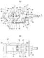
図1〜3は、本発明に係るトロイダル型無段変速機の一実施形態を示している。本実施形態のトロイダル型無段変速機を構成するトラニオン20は、一対の傾転軸21,22と、内平面24と背面70とを有し、中央部の内平面24に円孔25が開口した本体部23とを備える。また、本体部23は、内平面24の両側で内平面側に折り曲げられ、本体部23の両側に形成された一対の傾転軸21,22と連結する一対の折れ曲がり部26,26とを有する。一方の傾転軸21にはトラニオン軸38が一体化されており、トラニオン軸38の周囲には、トラニオン20と同期して傾転する駆動ピストン39、間座43及び安全ケーブル用のプーリ44が外嵌されている。
1 to 3 show an embodiment of a toroidal continuously variable transmission according to the present invention. The
駆動ピストン39のスリーブ部39aには、駆動シリンダ42(図5参照。)からの潤滑油が供給される給油孔59が形成されている。また、安全ケーブル用のプーリ44は円環状に形成されており、内周面からトラニオン20の背面側に位置する外周面に向けて貫通する潤滑孔71がプーリ44に形成されている。
The
トラニオン軸38には、給油孔59を含んで駆動ピストン39のスリーブ部39aの内周面と対向する位置に小径部72が形成されており、小径部72の外周面とスリーブ部39aの内周面との間に油路73を構成する。また、トラニオン軸38には、小径部72からプーリ44の潤滑孔71の内周面側開口と対向する位置まで軸方向に延び、間座43の内周面とともに三日月形状の油路74を構成する、平面状にカットされた切欠き部75が形成されている(図2参照。)。
The
トラニオン20の本体部23には、背面70から内平面24に向けて径方向に貫通する潤滑孔76が形成されている。そして、本体部23の潤滑孔76の背面側開口と、プーリ44の潤滑孔71の外周面側開口には、これらを連結する潤滑油供給部材77が接続されている。潤滑油供給部材77は、トラニオン20の背面70に加工されたタップ孔(図示せず)に抑え板78を挟んでボルト79をねじ込むことで、トラニオン20の背面70に固定される(図1(b)参照。)。
A
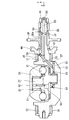
潤滑油供給部材77は、トラニオン20とともに傾転するので、支持板37に対しては相対回転することになる。潤滑油供給部材77は、本体部23の潤滑孔76とプーリ44の潤滑孔71とに連結されており、支持板37の外面の側方で、支持板37を跨ぐように配置されている(図3(a)参照。)。このため、図3(b)及び(c)に示されるように、トラニオン20が傾転軸21,22周りに傾転した時、潤滑油供給部材77が支持板37と干渉しないように、潤滑油供給部材77と支持板37の外面との間に所定の隙間sを持たせている。
Since the lubricating
なお、本実施形態の潤滑油供給部材77は丸パイプを用いたが、中空部材であればよく、その形状は任意である。また、潤滑油供給部材77の材質は、樹脂・銅・鉄等のいずれであってもよく、任意に選択できる。さらに、この潤滑油供給部材77の両端部と、プーリ44の潤滑孔71と、本体部23の潤滑孔76との連結部80,81は、ゴム系オイルシールや液体パッキンや紙系シール材等を利用して、油漏れの防止策を施してよい。
In addition, although the round pipe was used for the lubricating
このように構成されたトロイダル型無段変速機では、図1の矢印に示されるような潤滑経路に沿って、潤滑油がパワーローラ軸受部31まで供給される。まず、駆動ピストン39のスリーブ部39aに形成された給油孔59から供給された潤滑油が、トラニオン軸38の小径部72の外周面とスリーブ部39aの内周面との間に構成された油路73を通過する。油路73を通過した潤滑油は、切欠き部75と間座43との間に形成された三日月状の油路74を通過して、プーリ44に形成された潤滑孔71に導かれる。
In the toroidal type continuously variable transmission configured as described above, the lubricating oil is supplied to the power
さらに、潤滑油は、潤滑孔71から潤滑油供給部材77を通過して、トラニオン20の本体部23に形成された潤滑孔76へと送り込まれ、変位軸27に形成されたオイルキャッチ部60に供給される。なお、オイルキャッチ部60からパワーローラ軸受部31までの潤滑経路は、従来構造のものと同様である。
Further, the lubricating oil passes through the lubricating
従って、本実施形態のトロイダル型無段変速機によれば、トラニオン20の背面70に、パワーローラ軸受部31に潤滑油を供給するため、トラニオン20と同期して傾転する潤滑油供給部材77が接続されているので、トラニオン20の本体部23における潤滑孔の数を低減することができる。従って、孔の加工時間を短縮でき、加工コストを低減できる。また、潤滑孔の交差部分の数が低減されるので、交差部分のバリ取りやバリに対する特別な洗浄にかかる工数を低減することができ、加工コストを低減できる。さらに、トラニオン潤滑孔部の応力集中を緩和し、トラニオンの強度低下を防止することができる。また、潤滑油供給部材77は、トラニオン20の傾転動作を阻害したり、傾転によって捩れたり撓んだりすることがなく、安定して潤滑油をパワーローラ軸受部31に供給することができる。
Therefore, according to the toroidal type continuously variable transmission of the present embodiment, the lubricating
また、本発明のトロイダル型無段変速機によれば、トラニオン20には、背面70から内平面24に連通する潤滑孔76が形成されているので、トラニオン20の本体部23には、潤滑孔76が一本形成されればよく、加工時間を短縮でき、加工コストを低減できる。また、孔の交差部分が存在しないので、交差部分に発生するバリを無くすことができる。これにより、バリ取りやバリに対する特別の洗浄を実施する必要もなくなり、製造コストを低減することができる。
Further, according to the toroidal type continuously variable transmission of the present invention, the
なお、本発明は、上述した実施形態に限定されるものではなく、適宜な変形、改良等が可能である。
本実施形態では、トラニオン軸に外嵌された安全ケーブル用のプーリに潤滑孔を設けて、トラニオン軸に形成された油路からこの潤滑孔を介して潤滑油供給部材へと潤滑油を導いたが、潤滑孔を設ける部材は、トラニオンと同期して傾転する部材であればよく、間座や駆動ピストンであってもよい。また、潤滑孔を設けた専用の部材をトラニオン軸に外嵌するようにしてもよい。
Note that the present invention is not limited to the above-described embodiment, and appropriate modifications and improvements can be made.
In the present embodiment, a lubricating hole is provided in a pulley for a safety cable fitted on the trunnion shaft, and the lubricating oil is guided from the oil passage formed in the trunnion shaft to the lubricating oil supply member through the lubricating hole. However, the member provided with the lubrication hole may be a member that tilts in synchronization with the trunnion, and may be a spacer or a drive piston. Further, a dedicated member provided with a lubrication hole may be externally fitted to the trunnion shaft.
また、本発明のトロイダル型無段変速機は、図1に示すように変位軸とスラスト玉軸受の外輪が一体化されたものであってもよく、別体に構成されたものであってもよい。
本発明のトロイダル型無段変速機は、シングルキャビティタイプのトロイダル型無段変速機に限らず、ダブルキャビティタイプのものにも適用可能である。また、本実施形態では、バリエータ部品は、ハーフトロイダル型無段変速機について適用されているが、フルトロイダル型無段変速機にも適用可能である。
Further, the toroidal type continuously variable transmission of the present invention may be one in which the displacement shaft and the outer ring of the thrust ball bearing are integrated as shown in FIG. 1, or may be configured separately. Good.
The toroidal type continuously variable transmission of the present invention is not limited to a single cavity type toroidal continuously variable transmission, but can be applied to a double cavity type. In this embodiment, the variator part is applied to a half-toroidal continuously variable transmission, but can also be applied to a full toroidal continuously variable transmission.
10 トロイダル型無段変速機
12 入力ディスク
13 出力ディスク
20 トラニオン
21,22 傾転軸
23 本体部
24 内平面
29 パワーローラ
31 パワーローラ軸受部
37 支持板
38 トラニオン軸
39 駆動ピストン
43 間座
44 安全ケーブル用のプーリ
70 背面
76 潤滑孔
77 潤滑油供給部材
DESCRIPTION OF
Claims (3)
前記入力ディスクと前記出力ディスクとの間に傾転自在に転接するパワーローラと、
内平面と背面とを有する本体部と該本体部の両側に形成された一対の傾転軸とを備え、前記パワーローラを回転自在に支持しつつ、前記一対の傾転軸周りに傾転可能なトラニオンと、
前記パワーローラの回転を許容しつつ、前記パワーローラのスラスト荷重を支承するパワーローラ軸受部と、
を備えたトロイダル型無段変速機であって、
前記トラニオンの前記背面には、前記パワーローラ軸受部に潤滑油を供給するため、前記トラニオンと同期して傾転する潤滑油供給部材が接続されており、
前記潤滑油供給部材は、前記トラニオンを揺動自在且つ軸方向に変位自在に支持する支持板を跨いで、前記トラニオンの前記背面に接続されていることを特徴とするトロイダル型無段変速機。 An input disk and an output disk supported concentrically and rotatably independently of each other;
A power roller that inclines in a tiltable manner between the input disk and the output disk;
A main body having an inner plane and a back surface, and a pair of tilting shafts formed on both sides of the main body, and capable of tilting around the pair of tilting shafts while rotatably supporting the power roller Trunnion and
A power roller bearing that supports the thrust load of the power roller while allowing rotation of the power roller;
A toroidal-type continuously variable transmission with
To the back surface of the trunnion, in order to supply lubricating oil to the power roller bearing portion, a lubricating oil supply member that tilts in synchronization with the trunnion is connected ,
The toroidal continuously variable transmission, wherein the lubricating oil supply member is connected to the back surface of the trunnion across a support plate that supports the trunnion so as to be swingable and axially displaceable .
Priority Applications (1)
| Application Number | Priority Date | Filing Date | Title |
|---|---|---|---|
| JP2004063583A JP4433834B2 (en) | 2004-03-08 | 2004-03-08 | Toroidal continuously variable transmission |
Applications Claiming Priority (1)
| Application Number | Priority Date | Filing Date | Title |
|---|---|---|---|
| JP2004063583A JP4433834B2 (en) | 2004-03-08 | 2004-03-08 | Toroidal continuously variable transmission |
Publications (3)
| Publication Number | Publication Date |
|---|---|
| JP2005249141A JP2005249141A (en) | 2005-09-15 |
| JP2005249141A5 JP2005249141A5 (en) | 2006-11-30 |
| JP4433834B2 true JP4433834B2 (en) | 2010-03-17 |
Family
ID=35029797
Family Applications (1)
| Application Number | Title | Priority Date | Filing Date |
|---|---|---|---|
| JP2004063583A Expired - Fee Related JP4433834B2 (en) | 2004-03-08 | 2004-03-08 | Toroidal continuously variable transmission |
Country Status (1)
| Country | Link |
|---|---|
| JP (1) | JP4433834B2 (en) |
Families Citing this family (5)
| Publication number | Priority date | Publication date | Assignee | Title |
|---|---|---|---|---|
| JP4905012B2 (en) | 2006-06-02 | 2012-03-28 | 日本精工株式会社 | Toroidal continuously variable transmission |
| JP5057210B2 (en) * | 2007-01-16 | 2012-10-24 | 日本精工株式会社 | Toroidal continuously variable transmission |
| JP4872878B2 (en) * | 2007-10-03 | 2012-02-08 | 日本精工株式会社 | Toroidal continuously variable transmission |
| JP5187178B2 (en) * | 2008-01-18 | 2013-04-24 | 日本精工株式会社 | Toroidal continuously variable transmission |
| JP4962350B2 (en) * | 2008-02-27 | 2012-06-27 | 日本精工株式会社 | Toroidal continuously variable transmission |
-
2004
- 2004-03-08 JP JP2004063583A patent/JP4433834B2/en not_active Expired - Fee Related
Also Published As
| Publication number | Publication date |
|---|---|
| JP2005249141A (en) | 2005-09-15 |
Similar Documents
| Publication | Publication Date | Title |
|---|---|---|
| JP5077834B2 (en) | Toroidal continuously variable transmission | |
| JP4433834B2 (en) | Toroidal continuously variable transmission | |
| JP3932027B2 (en) | Toroidal continuously variable transmission | |
| US6746364B2 (en) | Toroidal-type continuously variable transmission | |
| JP6179332B2 (en) | Toroidal continuously variable transmission | |
| JP5288121B2 (en) | Toroidal continuously variable transmission | |
| JP3870525B2 (en) | Trunnion of toroidal continuously variable transmission | |
| JP5278569B2 (en) | Toroidal continuously variable transmission | |
| JP4141079B2 (en) | Toroidal continuously variable transmission | |
| JP5057210B2 (en) | Toroidal continuously variable transmission | |
| JP4761193B2 (en) | Toroidal continuously variable transmission | |
| JP4984138B2 (en) | Toroidal continuously variable transmission | |
| JP5673022B2 (en) | Toroidal continuously variable transmission | |
| WO2015118949A1 (en) | Trunnion for toroidal continuously variable transmission | |
| JP2001032899A (en) | Toroidal type continuously variable transmission | |
| JP2006002882A (en) | Toroidal continuously variable transmission | |
| JP2005265128A (en) | Toroidal continuously variable transmission | |
| JP5141669B2 (en) | Toroidal continuously variable transmission | |
| JP4734892B2 (en) | Toroidal continuously variable transmission | |
| JP4872878B2 (en) | Toroidal continuously variable transmission | |
| JP4623365B2 (en) | Toroidal continuously variable transmission | |
| JP2007205546A (en) | Toroidal type continuously variable transmission | |
| JP5082498B2 (en) | Toroidal continuously variable transmission | |
| JP2020069567A (en) | Main spindle device and machine tool | |
| JP2014169762A (en) | Toroidal type continuously variable transmission |
Legal Events
| Date | Code | Title | Description |
|---|---|---|---|
| RD04 | Notification of resignation of power of attorney |
Free format text: JAPANESE INTERMEDIATE CODE: A7424 Effective date: 20060327 |
|
| A521 | Written amendment |
Free format text: JAPANESE INTERMEDIATE CODE: A523 Effective date: 20061017 |
|
| A621 | Written request for application examination |
Free format text: JAPANESE INTERMEDIATE CODE: A621 Effective date: 20061017 |
|
| RD04 | Notification of resignation of power of attorney |
Free format text: JAPANESE INTERMEDIATE CODE: A7424 Effective date: 20071128 |
|
| A977 | Report on retrieval |
Free format text: JAPANESE INTERMEDIATE CODE: A971007 Effective date: 20090715 |
|
| A131 | Notification of reasons for refusal |
Free format text: JAPANESE INTERMEDIATE CODE: A131 Effective date: 20090728 |
|
| A521 | Written amendment |
Free format text: JAPANESE INTERMEDIATE CODE: A523 Effective date: 20090917 |
|
| TRDD | Decision of grant or rejection written | ||
| A01 | Written decision to grant a patent or to grant a registration (utility model) |
Free format text: JAPANESE INTERMEDIATE CODE: A01 Effective date: 20091208 |
|
| A01 | Written decision to grant a patent or to grant a registration (utility model) |
Free format text: JAPANESE INTERMEDIATE CODE: A01 |
|
| A61 | First payment of annual fees (during grant procedure) |
Free format text: JAPANESE INTERMEDIATE CODE: A61 Effective date: 20091221 |
|
| R150 | Certificate of patent or registration of utility model |
Ref document number: 4433834 Country of ref document: JP Free format text: JAPANESE INTERMEDIATE CODE: R150 Free format text: JAPANESE INTERMEDIATE CODE: R150 |
|
| FPAY | Renewal fee payment (event date is renewal date of database) |
Free format text: PAYMENT UNTIL: 20130108 Year of fee payment: 3 |
|
| FPAY | Renewal fee payment (event date is renewal date of database) |
Free format text: PAYMENT UNTIL: 20130108 Year of fee payment: 3 |
|
| FPAY | Renewal fee payment (event date is renewal date of database) |
Free format text: PAYMENT UNTIL: 20140108 Year of fee payment: 4 |
|
| LAPS | Cancellation because of no payment of annual fees |