JP4431358B2 - Clip for connecting windshield trim to vehicle - Google Patents
Clip for connecting windshield trim to vehicle Download PDFInfo
- Publication number
- JP4431358B2 JP4431358B2 JP2003359873A JP2003359873A JP4431358B2 JP 4431358 B2 JP4431358 B2 JP 4431358B2 JP 2003359873 A JP2003359873 A JP 2003359873A JP 2003359873 A JP2003359873 A JP 2003359873A JP 4431358 B2 JP4431358 B2 JP 4431358B2
- Authority
- JP
- Japan
- Prior art keywords
- clip
- groove
- teeth
- extension
- trim
- Prior art date
- Legal status (The legal status is an assumption and is not a legal conclusion. Google has not performed a legal analysis and makes no representation as to the accuracy of the status listed.)
- Expired - Fee Related
Links
- 230000000087 stabilizing effect Effects 0.000 claims description 4
- 230000000295 complement effect Effects 0.000 claims description 3
- 210000002105 tongue Anatomy 0.000 description 10
- 230000008878 coupling Effects 0.000 description 5
- 238000010168 coupling process Methods 0.000 description 5
- 238000005859 coupling reaction Methods 0.000 description 5
- 238000000034 method Methods 0.000 description 4
- 238000007789 sealing Methods 0.000 description 3
- 239000000853 adhesive Substances 0.000 description 2
- 230000001070 adhesive effect Effects 0.000 description 2
- 238000004519 manufacturing process Methods 0.000 description 2
- 239000000463 material Substances 0.000 description 2
- 230000006641 stabilisation Effects 0.000 description 2
- 238000011105 stabilization Methods 0.000 description 2
- 239000003381 stabilizer Substances 0.000 description 2
- 238000010276 construction Methods 0.000 description 1
- 238000010586 diagram Methods 0.000 description 1
- 230000007246 mechanism Effects 0.000 description 1
- 238000012986 modification Methods 0.000 description 1
- 230000004048 modification Effects 0.000 description 1
- 238000009966 trimming Methods 0.000 description 1
Images


Classifications
-
- B—PERFORMING OPERATIONS; TRANSPORTING
- B60—VEHICLES IN GENERAL
- B60R—VEHICLES, VEHICLE FITTINGS, OR VEHICLE PARTS, NOT OTHERWISE PROVIDED FOR
- B60R13/00—Elements for body-finishing, identifying, or decorating; Arrangements or adaptations for advertising purposes
- B60R13/04—External Ornamental or guard strips; Ornamental inscriptive devices thereon
-
- B—PERFORMING OPERATIONS; TRANSPORTING
- B60—VEHICLES IN GENERAL
- B60J—WINDOWS, WINDSCREENS, NON-FIXED ROOFS, DOORS, OR SIMILAR DEVICES FOR VEHICLES; REMOVABLE EXTERNAL PROTECTIVE COVERINGS SPECIALLY ADAPTED FOR VEHICLES
- B60J10/00—Sealing arrangements
- B60J10/20—Sealing arrangements characterised by the shape
- B60J10/26—Sealing arrangements characterised by the shape characterised by the surface shape
- B60J10/265—Sealing arrangements characterised by the shape characterised by the surface shape the surface being primarily decorative
-
- B—PERFORMING OPERATIONS; TRANSPORTING
- B60—VEHICLES IN GENERAL
- B60J—WINDOWS, WINDSCREENS, NON-FIXED ROOFS, DOORS, OR SIMILAR DEVICES FOR VEHICLES; REMOVABLE EXTERNAL PROTECTIVE COVERINGS SPECIALLY ADAPTED FOR VEHICLES
- B60J10/00—Sealing arrangements
- B60J10/30—Sealing arrangements characterised by the fastening means
-
- B—PERFORMING OPERATIONS; TRANSPORTING
- B60—VEHICLES IN GENERAL
- B60J—WINDOWS, WINDSCREENS, NON-FIXED ROOFS, DOORS, OR SIMILAR DEVICES FOR VEHICLES; REMOVABLE EXTERNAL PROTECTIVE COVERINGS SPECIALLY ADAPTED FOR VEHICLES
- B60J10/00—Sealing arrangements
- B60J10/70—Sealing arrangements specially adapted for windows or windscreens
-
- E—FIXED CONSTRUCTIONS
- E04—BUILDING
- E04F—FINISHING WORK ON BUILDINGS, e.g. STAIRS, FLOORS
- E04F19/00—Other details of constructional parts for finishing work on buildings
- E04F19/02—Borders; Finishing strips, e.g. beadings; Light coves
-
- Y—GENERAL TAGGING OF NEW TECHNOLOGICAL DEVELOPMENTS; GENERAL TAGGING OF CROSS-SECTIONAL TECHNOLOGIES SPANNING OVER SEVERAL SECTIONS OF THE IPC; TECHNICAL SUBJECTS COVERED BY FORMER USPC CROSS-REFERENCE ART COLLECTIONS [XRACs] AND DIGESTS
- Y10—TECHNICAL SUBJECTS COVERED BY FORMER USPC
- Y10T—TECHNICAL SUBJECTS COVERED BY FORMER US CLASSIFICATION
- Y10T24/00—Buckles, buttons, clasps, etc.
- Y10T24/30—Trim molding fastener
- Y10T24/303—Trim molding fastener having laterally extending biasing appendage
-
- Y—GENERAL TAGGING OF NEW TECHNOLOGICAL DEVELOPMENTS; GENERAL TAGGING OF CROSS-SECTIONAL TECHNOLOGIES SPANNING OVER SEVERAL SECTIONS OF THE IPC; TECHNICAL SUBJECTS COVERED BY FORMER USPC CROSS-REFERENCE ART COLLECTIONS [XRACs] AND DIGESTS
- Y10—TECHNICAL SUBJECTS COVERED BY FORMER USPC
- Y10T—TECHNICAL SUBJECTS COVERED BY FORMER US CLASSIFICATION
- Y10T24/00—Buckles, buttons, clasps, etc.
- Y10T24/30—Trim molding fastener
- Y10T24/309—Plastic type
Description
本発明はクリップ、特にクリップ及び、車両にトリムストリップを取り付けるためにクリップを使用する方法に関する。 The present invention relates to clips, particularly clips and methods of using clips to attach trim strips to vehicles.
多くの車両(すなわち自動車)は、ウインドシールドと、ウインドシールドが取り付けられるボディ開口との間のギャップを被覆及び/又はシールするためにトリムストリップ(若しくはトリム)を使用する。幾つかの場合には、トリムストリップはウインドシールドを所定の位置に物理的に保持するのを助ける。別の場合には、トリムストリップは、ウインドウをボディ開口に固定する接着剤及び/又はガスケットを被覆するためにのみ付加され、これにより、より美観的に好感される外観を提供する。 Many vehicles (ie automobiles) use trim strips (or trims) to cover and / or seal the gap between the windshield and the body opening to which the windshield is attached. In some cases, the trim strip helps to physically hold the windshield in place. In other cases, the trim strip is added only to cover the adhesive and / or gasket that secures the window to the body opening, thereby providing a more aesthetically pleasing appearance.
慣用的なトリムストリップは、しばしばウインドシールドとボディ開口との間のギャップに亘っており、ウインドシールドの縁部と、ウインドシールド開口に隣接したボディの部分とを僅かに超えて延びている。接着剤及び/又はガスケットは、ウインドシールドと車両ボディとの間の一次的なシールを提供するが、シールは汚れ及びくずがギャップに進入するのも防ぐ。有効に機能するために、トリムストリップはしっかりと取り付けられなければならず、その幅に亘って安定していなければならない。理想的には、トリムストリップはストリップの幅の比較的中央で取り付けられている。この位置決めは、トリムストリップが幅広になるほど重要である。取付けの悪いトリムストリップは、意図せずに外れるか又は汚れ及びくずをギャップに進入させる。 Conventional trim strips often span the gap between the windshield and the body opening and extend slightly beyond the edge of the windshield and the portion of the body adjacent to the windshield opening. The adhesive and / or gasket provides a primary seal between the windshield and the vehicle body, but the seal also prevents dirt and debris from entering the gap. In order to function effectively, the trim strip must be securely attached and stable across its width. Ideally, the trim strip is mounted relatively centrally in the width of the strip. This positioning is more important as the trim strip becomes wider. A poorly installed trim strip will unintentionally dislodge or allow dirt and debris to enter the gap.
許容できる公差により別の問題が生じる。トリムストリップは通常、ウインドシールド開口に隣接したボディ上に位置決めされた取付け穴又はポストを使用して車両ボディに取り付けられている。ウインドシールド開口の形状及び/又は取付け穴又はポストの位置決めの製造公差は、トリムストリップが、取り付けられた時に不均一に見えるようにするおそれがあるか、又はトリムストリップがギャップを完全に被覆しなくするおそれがある。 Another problem arises with acceptable tolerances. The trim strip is typically attached to the vehicle body using mounting holes or posts positioned on the body adjacent to the windshield opening. Manufacturing tolerances in the shape of the windshield opening and / or positioning of the mounting holes or posts may cause the trim strip to appear non-uniform when installed, or the trim strip does not completely cover the gap There is a risk.
したがって、必要とされていることは、これらの問題及びその他の問題を最小限に抑制する、トリムストリップを車両に固定するためのシステム及び方法である。 Therefore, what is needed is a system and method for securing a trim strip to a vehicle that minimizes these and other problems.
したがって、本発明の課題は、T字形スタッドの不正確な位置にも拘わらずトリムストリップを車両ボディに均一に固定するためのクリップ及び方法を提供することである。 Accordingly, it is an object of the present invention to provide a clip and method for uniformly securing a trim strip to a vehicle body despite the incorrect location of the T-shaped stud.
本発明の実施形態は、トリムストリップを車両ボディに固定するためのクリップを提供する。クリップの第1の部分は、トリムストリップ上の対応するフランジ装置と係合するように構成されたフランジ装置を有している。クリップの第2の部分は、第1の部分に摺動可能に結合し、第1の軸線に沿って第1の部分と第2の部分との相対移動を許容する。第2の部分は、車両ボディのT字形スタッドにしっかりと取り付けられるように構成されている。 Embodiments of the present invention provide a clip for securing a trim strip to a vehicle body. The first portion of the clip has a flange device configured to engage a corresponding flange device on the trim strip. The second portion of the clip is slidably coupled to the first portion and allows relative movement between the first portion and the second portion along the first axis. The second part is configured to be securely attached to the T-shaped stud of the vehicle body.
本発明の別の実施形態は、第1の部分と、第2の部分と、舌片とを有するクリップを車両のT字形スタッドに取り付け、クリップが車両と適切に整合させられるように、舌片が車両と接触するまで第1の部分を第2の部分に対して摺動させることを含む方法を提供する。 Another embodiment of the invention is to attach a clip having a first portion, a second portion, and a tongue piece to a T-shaped stud of a vehicle so that the clip is properly aligned with the vehicle. Providing a method including sliding the first portion relative to the second portion until the vehicle contacts the vehicle.
本発明の別の実施形態は、車両に固定的に取り付けられるように構成された第1の部分と、第1の部分に摺動可能に係合しかつトリムの取付けのために構成された第2の部分とを含んでおり、第1の部分と第2の部分との摺動可能な係合が車両に対するトリムの位置決めを許容するクリップを提供する。 Another embodiment of the present invention includes a first portion configured to be fixedly attached to a vehicle, and a first portion slidably engaged with the first portion and configured for attachment of a trim. And a slidable engagement between the first part and the second part to provide a clip that allows positioning of the trim relative to the vehicle.
本発明のさらに別の実施形態は、トリムをボディに固定するためのクリップを提供する。クリップの第1の部分は、ボディの面に対して係合されるように構成された第1の側と、トリムと係合するように構成された第2の反対の側とを有している。第2の側は、トリムにしっかりと結合するための装置を有している。クリップの第2の部分はボディに取り付けられるように構成されている。第2の部分は第1の部分におけるチャネル内に配置されている。第1の部分は第1の軸線に沿って第2の部分に対して摺動可能である。第1の部分に結合されたトリムのボディ上での位置を調節するために第1の部分が第2の部分に対して移動させられてよい。 Yet another embodiment of the present invention provides a clip for securing a trim to a body. The first portion of the clip has a first side configured to engage against a face of the body and a second opposite side configured to engage the trim. Yes. The second side has a device for securely joining the trim. The second portion of the clip is configured to be attached to the body. The second part is disposed in the channel in the first part. The first portion is slidable relative to the second portion along the first axis. The first portion may be moved relative to the second portion to adjust the position on the body of the trim coupled to the first portion.
本発明の別の実施形態、特徴及び利点と、本発明の様々な実施形態の構造及び操作とは、添付の図面を参照に以下に詳細に説明される。 Further embodiments, features, and advantages of the present invention, as well as the structure and operation of the various embodiments of the present invention, are described in detail below with reference to the accompanying drawings.
本明細書に添付されかつ明細書の一部を構成した添付図面は、本発明を例示しており、詳細な説明と共に、本発明の原理をさらに説明するために、また当業者が本発明を形成及び使用することを可能にするために働く。 The accompanying drawings, which are included in and constitute a part of this specification, illustrate the invention and, together with the detailed description, further explain the principles of the invention and allow those skilled in the art to understand the invention. Works to allow you to form and use.
本発明は以下に添付の図面を参照に説明される。図面中、同一の参照符号は同一又は機能的に類似のエレメントを表している。付加的に、参照符号の左側の数字は、その参照符号が最初に又は主として使用された図面を表している。 The present invention will now be described with reference to the accompanying drawings. In the drawings, identical reference numbers indicate identical or functionally similar elements. Additionally, the number to the left of the reference number represents the drawing in which the reference number was first or primarily used.
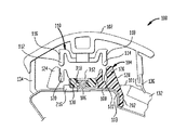
図1は本発明の実施形態によるシステム100を示している。システム100は、トリミング装置102(例えばトリム、トリムストリップ又は同様のもの)と、クリップ104と、ボディ108(例えば車両ボディ、ボディ部分等)に固定されたT字形スタッド106(例えばファスナ)とを有している。トリム102は、第1及び第2のフランジ112及び114を有する結合装置110を含んでいる。フランジ112及び114は歯116及び118を有している。歯116及び118は、クリップ104の第1の部分128(例えば第1のボディ部分)のフランジ124及び126における歯120及び122と係合する。第1の部分128のフランジ124及び126は特定の形状及び寸法でありかつその1つの面に歯120及び122を有するように示されているが、別の寸法及び形状を使用することができるが認められるであろう。クリップ104の第2の部分130(例えば第2のボディ部分)は第1の部分128と摺動可能に係合し、クリップ104をT字形スタッド106に固定するために使用される。
FIG. 1 illustrates a
対応するフランジ112,114及び124,126は、トリム102とクリップ104とを結合するために互いに係合する限り、あらゆる数の形式で構成されることができる。さらに、クリップ104及び結合装置110における2つのフランジの使用は決定的ではない。その代わりに、安定性及びコストを考慮することに基づきあらゆる数のフランジが使用されてよい。同じ結果を得るためにこの構造にこれらの変更及びその他の変更が行われてよいことは当業者に明らかであろう。
Corresponding
トリム102は、車両のウインドシールド132の縁部とボディ108との間のギャップ101を被覆及びシールする。トリム102は、トリム102の両端部から延びた第1及び第2のシール装置134,136を有している。シール装置134,136は、トリム102をウインドシールド132及びボディ108にシールさせるために使用することができる。トリム102の一般的な構成及び目的はこの分野においてよく知られていることが認められるであろう。また、様々なプロフィルを有する他のトリムストリップ、種々異なるシール又は同様のものが使用されることができ、本発明の範囲内で考慮されることが認められるであろう。
The
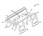
図2は本発明の実施形態によるクリップ104の第1の部分128の斜視図を示している。第1の部分128は縁部200を有しており、この縁部から1対の舌片202及び204が延びている。図1に示したように、舌片202及び204はその形状において、概してボディ108の縁部又はリッジ部分103に対応している。トリム102をボディ108におけるウインドシールド開口と整合させるためにクリップ104が所望の最適な位置に配置されると、舌片202及び204がボディ108のリッジ部分103に当接して位置決めされる。舌片202及び204の正確な構成は、ボディ108の適切な部分と係合又は接触するための寸法及び形状を有している限り、決定的ではないことが認められるであろう。さらに、2つの舌片202及び204が示されているが、安定性及びコストを考慮してその他の数の舌片が使用されてもよい。同じ結果を達成するためにこの構造にこれらの変更及びその他の変更が加えられることは当業者に明らかであろう。
FIG. 2 shows a perspective view of the
引き続き図2を参照すると、第1の部分128は開口206をも有しており、この開口206には第2の部分130が収容される。開口206のそれぞれの側には、スロット212及び214を備えた区分208及び210が設けられている。この図には示されていないが、区分208及び210の下側には歯400及び402(図4参照)が設けられており、これらの歯は、第2の部分130の第1及び第2の区分306及び308(図3参照)に設けられた歯302及び304(図3参照)と係合するように構成されている。以下に詳細に説明するように、歯302,304及び歯400,402は、互いに噛み合う(又は一方向にのみ摺動する)ので、ラチェット装置の一部であると考えることができる。
With continued reference to FIG. 2, the
引き続き図2を参照すると、第1の部分128は、第1の部分から延びた安定化装置216(例えば耳又は同様のもの)を選択的に有することもできる。図4に示したように、安定化装置216は、第1の部分128の両側から対称的に延びた第1及び第2の部分を有することができる。図5から図9までに示したように、安定化装置216は、クリップ104がボディ108に結合された場合にこのクリップを安定させるのを助けるために使用することができる。このことは、部分的に、第1の部分128が形成された材料の自然な弾性により達成される。この自然の弾性は、安定化装置216とボディ108との間にバイアス力を加える。
With continued reference to FIG. 2, the
図3は本発明の実施形態によるクリップ104の第2の部分130の斜視図である。前記エレメントに加え、第2の部分130は第3の(又は主要な)区分310を有している。第3の区分310はキャビティ312を有している。キャビティ312は、表面300における開口314を介して見える。表面300から開口314内へストッパ316が延びている。キャビティ312には肩部318が配置されている(図1参照)。クリップ104をボディ108に固定するためのストッパ316及び肩部318の働きを以下に説明する。
FIG. 3 is a perspective view of the
図4はクリップ104の第1の部分128の側面図であり、開口206と、横方向に延びた溝404とを示しており、これらの開口206及び溝404は、第2の部分130を収容するように構成されている。上に説明したように、第2の部分130が溝404に沿って第1の部分128の開口206に挿入される時に、歯400,402及び302,304のラチェット機能が、溝404に沿って第1の部分128に対して一方向で(例えばこの図の紙面の奥に向かって)第2の部分130の通常の移動を許容する。歯は、第1の部分128を形成した材料の自然の弾性によって係合させられて保持される。この弾性により、部分208及び210はばね部材のように作用する。第2の部分130を溝404に沿って第1の部分128に対して反対方向に(例えば図面の手前に向かって)移動させるためには、区分208及び210(図2)は僅かに持ち上げられる必要がある。部分208及び210を持ち上げることにより、歯302,304は歯400,402から解離する。
FIG. 4 is a side view of the
図5から図8までは本発明の実施形態による車両ボディへのクリップ104の取付けを示している。
FIGS. 5-8 show the attachment of the
まず図5を参照すると、第1のステージにおいて、ボディ108の区分500(例えばAピラー)に固定された1つのT字形スタッド106が、クリップ104を収容するために選択される。
Referring first to FIG. 5, in the first stage, one T-shaped
図6は、クリップ104をボディ108に結合する第2のステージを示している。第2のステージでは、クリップ104はT字形スタッド106上に位置決めされ、T字形スタッド106の頭部が第2の部分130のストッパ316を逸らせ、キャビティ312に進入するまで、T字形スタッド106に対して下方へ押圧される。この初期位置において、舌片202及び204は概して車両ボディ108の縁部103から距離Dだけ間隔を置かれている。この間隔は、縁部103に対するT字形スタッド106の不正確な整合により生じる。
FIG. 6 shows a second stage coupling the
図7はクリップ104をボディ108に結合する第3のステージを示している。第3のステージにおいてクリップ104は矢印700の方向に移動させられる。この移動の間、T字形スタッド106は肩部318としっかりと係合させられる。T字形スタッド106の頭部が肩部318と完全に係合させられると、ストッパ316が、逸らされた位置から下方へスナップ係合し、T字形スタッド106を肩部318に対して所定の位置に固定し、T字形スタッド106の頭部がこの完全に係合した位置から引っ込むことを防止する。T字形スタッド106と肩部318とのこの係合はクリップ140をボディ108に固定する。
FIG. 7 shows a third stage for coupling the
図8は、本発明による、クリップ104をボディ108に結合する第4の又は調節ステージを示している。第4のステージでは、第1の部分128が矢印800の方向に摺動させられる。この摺動は、第1の部分128(移動させられている)と第2の部分130(T字形スタッド106に固定されている)との相対移動を生ぜしめる。歯302及び304が歯400及び402に噛み合うことにより、矢印800によって示された方向でのみ妨げられない移動が生ぜしめられる。第1の部分128の移動は、舌片202及び204がボディ108の縁部103と相互作用した時に終了する。この位置において、クリップ104は縁部103に当接して位置決めされ、ボディ108におけるT字形スタッド106の不正確な位置にも拘らず縁部と正確に整合させられる。
FIG. 8 illustrates a fourth or adjustment stage that couples
図9は、ウインドシールド132の縁部を取り囲む複数のT字形スタッド106に結合された複数のクリップ104を有する車両ボディ108の部分900を示している。トリム102をウインドシールド132の周囲の適切な位置に維持するために、多数のT字形スタッド106及びクリップ104がこの形式では使用される。トリム102を取り付けるために必要とされるクリップ及びT字形スタッドの正確な数は、この分野において知られるように、所定の仕様に基づき決定される。
FIG. 9 shows a
全てのクリップ104が装着されると、トリム102がクリップ104に取り付けられる。トリム102は手作業で又はゴム製小槌を用いて各クリップ104に押し付けられる。トリム102は、各クリップ104によって、相補的な係合する歯116,118及び120,122を介して所定の位置に保持される。前記のように、ボディ108に固定されているクリップ104に基づき、トリム102は、美観的に好ましい形式で縁部103と整合させられ、所定の位置にしっかりと保持される。ボディ108の部分、クリップ104及びトリム102の部分の寸法及び形状は変更することができ、その他の設計上の選択に従って望ましいいかなる寸法をも採用することができることは認められるであろう。
When all the
所要の公差を考慮すると、前記の本発明の実施形態は従来のシステムと比較して多くの利点を有する。例えば、T字形スタッド106は所望の位置においてボディ108に取り付けられる。しかしながら、所望の位置は、製造上の要求により、車両の縁部に沿って数ミリメートル変化することがある。このT字形スタッドの不正確な位置にも拘らず、本発明のクリップによりトリムストリップは一貫してボディ108の縁部103から所定の距離に配置される。一方向摺動機構により、第1の部分128はT字形スタッド106に対して移動することができる。これにより、第1の部分128がウインドシールド132の周囲に均一に位置決めされることを保証しながら、公差を補償するための調整が可能となる。このことは、トリム102がウインドシールド132の周囲に均一に位置決めされることをも保証し、このことは均一で美的な外観を生ぜしめる。
In view of the required tolerances, the embodiments of the invention described above have many advantages over conventional systems. For example, the T-shaped
図1から図9までを再び参照すると、クリップ104がT字形スタッド106に結合され、トリム102がクリップ104に結合されると、歯116,118,120及び122はトリム102がAピラー500に沿って上下に(例えば垂直に)移動するのを許容する。つまり、トリム102は、トリム102をあらゆる所望の垂直方向位置に位置決めするために、垂直方向に移動させられることができる。垂直方向で位置決めされた後、トリム102はAピラー500に固定されることができる。また、歯116,118,120及び122の使用は、Aピラー500に沿ったトリム102の熱膨張を許容することができる。
Referring again to FIGS. 1 through 9, when
結論
本発明の様々な実施形態が上に説明されたが、それらの実施形態は例としてのみ示されており、限定として示されていないということが理解されるべきである。本発明の思想及び範囲から逸脱することなく前記実施形態の形態及び詳細の様々な変更を行うことができることが当業者には明らかとなるであろう。つまり、本発明の広さ及び範囲は、前記の典型的な実施形態のうちのいかなるものによっても限定されるべきではなく、請求項及びその均等物に基づいてのみ定義されるべきである。
CONCLUSION While various embodiments of the present invention have been described above, it should be understood that the embodiments are shown by way of example only and not as limitations. It will be apparent to those skilled in the art that various modifications can be made in the form and details of the embodiments without departing from the spirit and scope of the invention. In other words, the breadth and scope of the present invention should not be limited by any of the above-described exemplary embodiments, but should be defined only in accordance with the claims and their equivalents.
100 システム、 102 トリムストリップ、 103 縁部、 104 クリップ、 106 T字形スタッド、 108 ボディ、 110 結合装置、 112,114 フランジ、 116,118,120,122 歯、 124,126 フランジ、 128 第1の部分、 130 第2の部分、 132 ウインドシールド、 134,136 シール装置、 200 縁部、 202,204 舌片、 206 開口、 208,210 区分、 212,214 スロット、 216 安定化装置、 302,304 歯、 305,308 区分、 312 キャビティ、 314 開口、 316 ストッパ、 318 肩部、 400,402 歯、 500 区分又はAピラー 100 system, 102 trim strip, 103 edge, 104 clip, 106 T-shaped stud, 108 body, 110 coupling device, 112, 114 flange, 116, 118, 120, 122 teeth, 124, 126 flange, 128 first part , 130 second part, 132 windshield, 134,136 sealing device, 200 edge, 202,204 tongue, 206 opening, 208,210 section, 212,214 slot, 216 stabilizer, 302,304 teeth, 305,308 section, 312 cavity, 314 opening, 316 stopper, 318 shoulder, 400,402 teeth, 500 section or A-pillar
Claims (7)
第1の部分(128)と第2の部分(130)とを有しており、
前記第1の部分(128)が、該第1の部分(128)の第1の側から第2の側まで延びた、互いに間隔を置きながら横方向に延びた第1の溝及び第2の溝(404)を有しており、該第1の溝及び第2の溝(404)がそれぞれ実質的にその長さに亘って歯を有しており、
前記第1の部分(128)がさらに、第1の部分(128)の第1の側から第2の側まで、第1の溝及び第2の溝(404)に対して平行に、第1の溝と第2の溝(404)との間に延びた開口(206)を有しており、
前記第1の部分(128)がさらに、車両ボディ(108)と相互作用するように構成された舌片装置(202,204)と、
トリムストリップ(102)に取り付けられたトリムストリップ(102)のフランジ装置(112,114)と係合するように構成された第1の部分(128)のフランジ装置(124,126)とを有しており、
前記第2の部分(130)が、中央開口(314)を有するボディ部分(310)を有しており、前記中央開口(314)が、車両のT字形スタッド(106)と係合するように構成されており、
前記第2の部分(130)がさらに、前記ボディ部分(310)の第1の側及び第2の側から延びた、互いに間隔を置いて配置された第1の延長部(306)及び第2の延長部(308)を有しており、前記第1の延長部(306)及び第2の延長部(308)が、その長さに沿って、第1の溝及び第2の溝(404)の歯(400,402)に対して相補的でかつ対応する歯(302,304)を有しており、
前記ボディ部分(310)が第1の部分(128)の側部における開口を通じて受容され、これにより、第1の延長部(306)及び第2の延長部(308)が第1の溝及び第2の溝のうちの対応する溝(404)に受容され、第1の部分(128)と第2の部分(130)との相対移動を許容するように第2の部分(130)が第1の部分(128)内に摺動可能に連結されており、
第1の延長部(306)及び第2の延長部(308)の歯(302,304)が、第1の溝及び第2の溝(404)の歯(400,402)に対して係合するように構成されており、これにより、前記相対移動が、一方向でのみ生じ、T字形スタッド(106)に対する舌片装置(202,204)の位置の調整を許容しかつその後に前記位置を維持するようになっており、これにより、(a)第2の部分(130)がT字形スタッド(106)に固定され、(b)第1の部分(128)が、舌片装置(202,204)を車両ボディ(108)に位置決めするために第2の部分(130)に対して移動させられた後、舌片装置(202,204)が車両ボディ(108)に接触させられることを特徴とする、トリムストリップ(102)を車両ボディ(108)に固定するためのクリップ。 In clip (104) for securing trim strip (102) to vehicle body (108) ,
A first portion (128) and a second portion (130) ;
The first portion (128) extends from the first side to the second side of the first portion (128) and extends in a laterally spaced first groove and a second direction. A groove (404) , the first groove and the second groove (404) each having teeth substantially over its length;
The first portion (128) is further parallel to the first groove and the second groove (404) from the first side to the second side of the first portion (128) . An opening (206) extending between the first groove and the second groove (404) ,
A tongue device (202, 204) , wherein the first portion (128) is further configured to interact with the vehicle body (108) ;
And a trim strip flange apparatus of the first portion configured to engage the flange device (112, 114) trim strip attached to the (102) (102) (128) (124, 126) And
Said second portion (130) has a body portion (310) having a central opening (314), such that said central opening (314) is engaged with the vehicle T-shaped studs (106) Configured,
The second portion (130) further extends from the first side and the second side of the body portion (310) and is spaced apart from the first extension (306) and the second. It has an extension of (308), before Symbol first extension portion (306) and a second extension portion (308) is, along its length, a first groove and a second groove ( 404) teeth (302, 304) complementary to and corresponding to teeth (400, 402) ,
The body portion (310) is received through an opening in the side of the first portion (128) so that the first extension (306) and the second extension (308) are in the first groove and the second. The second portion (130) is received in the corresponding one of the two grooves (404) and the second portion (130) is first to allow relative movement between the first portion (128) and the second portion (130) . Is slidably connected in the part (128) of
The teeth (302, 304) of the first extension (306) and the second extension (308) engage the teeth (400, 402) of the first and second grooves (404). is configured to, by this, the relative movement occurs only in one direction, allowing adjustment of the position of the tongue device (202, 204) for T-shaped studs (106) and then to the position So that (a) the second part (130) is secured to the T-shaped stud (106) and (b) the first part (128) is attached to the tongue device (202, after being moved relative to the second portion (130) to position the 204) vehicle body (108), characterized in that the tongue device (202, 204) is brought into contact with the vehicle body (108) The trim strip (102) Clips for fixing to both the body (108).
Applications Claiming Priority (2)
| Application Number | Priority Date | Filing Date | Title |
|---|---|---|---|
| US41908102P | 2002-10-18 | 2002-10-18 | |
| US10/680,423 US7140079B2 (en) | 2002-10-18 | 2003-10-08 | Clip for coupling windshield trim to a vehicle |
Publications (3)
| Publication Number | Publication Date |
|---|---|
| JP2004276905A JP2004276905A (en) | 2004-10-07 |
| JP2004276905A5 JP2004276905A5 (en) | 2006-11-30 |
| JP4431358B2 true JP4431358B2 (en) | 2010-03-10 |
Family
ID=32599969
Family Applications (1)
| Application Number | Title | Priority Date | Filing Date |
|---|---|---|---|
| JP2003359873A Expired - Fee Related JP4431358B2 (en) | 2002-10-18 | 2003-10-20 | Clip for connecting windshield trim to vehicle |
Country Status (2)
| Country | Link |
|---|---|
| US (1) | US7140079B2 (en) |
| JP (1) | JP4431358B2 (en) |
Families Citing this family (20)
| Publication number | Priority date | Publication date | Assignee | Title |
|---|---|---|---|---|
| US7222404B1 (en) | 2005-07-26 | 2007-05-29 | Honda Motor Co., Ltd. | Trim clip installation tool and method |
| JP4252987B2 (en) * | 2005-11-01 | 2009-04-08 | 日本板硝子株式会社 | Glass with molding |
| JP2007125958A (en) * | 2005-11-02 | 2007-05-24 | Nippon Pop Rivets & Fasteners Ltd | Roof molding mounting device |
| JP4260159B2 (en) * | 2005-11-28 | 2009-04-30 | トヨタ車体株式会社 | Mounting structure of vehicle pillar garnish |
| JP4725365B2 (en) * | 2006-03-01 | 2011-07-13 | 日産自動車株式会社 | Engaging and fixing structure and engaging and fixing method |
| FR2903462B1 (en) * | 2006-07-05 | 2012-04-06 | Fabi Automobile | FIXING SYSTEM FOR AN EXTENDED BODY PIECE OF A MOTOR VEHICLE BODY, AND AN EXTENDED BODY PART OF A MOTOR VEHICLE BODY |
| FR2920720B1 (en) * | 2007-09-06 | 2010-01-08 | Peugeot Citroen Automobiles Sa | WINDSCREEN WINDSCREEN OF A MOTOR VEHICLE AND A MOTOR VEHICLE COMPRISING AT LEAST ONE SUCH. |
| JP5150187B2 (en) * | 2007-10-03 | 2013-02-20 | 株式会社ファルテック | Sunroof decorative material |
| CA2666774A1 (en) * | 2008-05-22 | 2009-11-22 | Royal Group, Inc. | Moulding assembly |
| GB0914571D0 (en) | 2009-08-20 | 2009-09-30 | Pilkington Group Ltd | Vehicle glazing |
| US20140338276A1 (en) * | 2011-07-11 | 2014-11-20 | Cory Halischuk | Fastening a Ceiling Trim |
| US8876183B2 (en) * | 2012-09-06 | 2014-11-04 | Ford Global Technologies, Llc | High retention trim attachment system |
| US8615962B1 (en) * | 2013-01-14 | 2013-12-31 | GM Global Technology Operations LLC | Retention feature for automotive deco trim |
| US9079536B2 (en) * | 2013-02-04 | 2015-07-14 | Illinois Tool Works Inc. | Sliding grip clip for mounting a ski rack |
| US9114764B2 (en) * | 2013-06-24 | 2015-08-25 | GM Global Technology Operations LLC | Attachment assembly |
| KR101997271B1 (en) * | 2013-07-19 | 2019-10-02 | 현대자동차주식회사 | variable pedal ratio type pedal |
| US9387743B2 (en) * | 2013-12-18 | 2016-07-12 | Taylor Made Group, Llc | Slide lock attachment system |
| DE102016117454B3 (en) * | 2016-09-16 | 2017-12-07 | Richard Fritz Holding Gmbh | Disc unit with attachment |
| CN110997465B (en) * | 2017-08-08 | 2024-03-26 | 标致雪铁龙汽车股份有限公司 | Vehicle with front pillar assembly |
| FR3092049B1 (en) | 2019-01-29 | 2020-12-25 | Psa Automobiles Sa | VEHICLE INCLUDING A GLASS TRIM SUPPORT ASSEMBLED BY CLINCHING |
Family Cites Families (21)
| Publication number | Priority date | Publication date | Assignee | Title |
|---|---|---|---|---|
| US2681487A (en) * | 1952-05-03 | 1954-06-22 | Illinois Tool Works | Molding clip |
| US3074134A (en) * | 1961-04-14 | 1963-01-22 | Thompson Ind Inc | Fastening means |
| US3246440A (en) * | 1963-07-24 | 1966-04-19 | Chicago United Products Compan | Fastener assembly |
| US3188730A (en) * | 1964-01-15 | 1965-06-15 | Chicago United Products Compan | Method of finishing automobile panel and securing trim thereto |
| ES161910Y (en) | 1967-11-06 | 1971-10-16 | Warren Fastener Corporation | ADAPTER DEVICE FOR FASTENING GARNISHES ON A SUPPORT. |
| US3981697A (en) * | 1975-09-22 | 1976-09-21 | General Motors Corporation | Carrier and clamp assembly for a vehicle window |
| GB1602690A (en) | 1977-09-05 | 1981-11-11 | United Carr Gmbh | Clip |
| FR2556423B1 (en) | 1983-12-09 | 1986-09-19 | Legrand Sa | FIXING ACCESSORY SPECIFIC TO THE SUBJECT OF ANY ARTICLE, FOR EXAMPLE CHUTE OR CONDUIT, TO ANY SUPPORT, FOR EXAMPLE PERFORATED PLATE, CHASSIS UPRIGHT OR CABINET DOOR, PARTICULARLY FOR ELECTRICAL EQUIPMENT |
| US4637774A (en) * | 1984-02-29 | 1987-01-20 | Toyoda Koki Kabushiki Kaisha | Industrial robot |
| US4636915A (en) | 1985-08-20 | 1987-01-13 | Siemens Energy & Automation, Inc. | Fastener having dual teeth |
| US4698882A (en) * | 1987-02-26 | 1987-10-13 | General Motors Corporation | Molding attaching clip |
| US4860409A (en) * | 1988-08-01 | 1989-08-29 | General Motors Corporation | Molding retention clip assembly |
| FR2649762B1 (en) | 1989-07-17 | 1991-10-31 | Itw De France | ATTACHED |
| US5096753A (en) | 1990-02-12 | 1992-03-17 | Mccue Corporation | Protective strip assembly |
| DE4014589C1 (en) | 1990-05-07 | 1991-08-08 | Trw United-Carr Gmbh & Co Kg, 6753 Enkenbach-Alsenborn, De | |
| JP2545843Y2 (en) | 1991-05-15 | 1997-08-27 | 東海興業株式会社 | Car mall |
| US5202172A (en) * | 1991-05-20 | 1993-04-13 | General Motors Corporation | Molding and retainer assembly |
| US5283096A (en) | 1992-04-23 | 1994-02-01 | Boston Metal Products Corp. | Resilient strip for protective strip assembly |
| US5339501A (en) | 1993-02-24 | 1994-08-23 | Illinois Tool Works Inc. | Snap and ratchet panel fastener and support assembly |
| US6772484B2 (en) * | 2000-09-28 | 2004-08-10 | Toyoda Gosei Co., Ltd | Mounting structure for mounting a resin molded article to a body panel |
| JP4416336B2 (en) * | 2001-01-29 | 2010-02-17 | 株式会社ニフコ | Mall mounting clip and mall mounting structure |
-
2003
- 2003-10-08 US US10/680,423 patent/US7140079B2/en not_active Expired - Fee Related
- 2003-10-20 JP JP2003359873A patent/JP4431358B2/en not_active Expired - Fee Related
Also Published As
| Publication number | Publication date |
|---|---|
| US7140079B2 (en) | 2006-11-28 |
| JP2004276905A (en) | 2004-10-07 |
| US20040117951A1 (en) | 2004-06-24 |
Similar Documents
| Publication | Publication Date | Title |
|---|---|---|
| JP4431358B2 (en) | Clip for connecting windshield trim to vehicle | |
| JP5408068B2 (en) | Wire harness clip and method of mounting a wire harness clip on a vehicle body | |
| JPS6274397A (en) | Apparatus for mounting seat cover for car | |
| JP2007302186A (en) | Vehicular door frame | |
| JP3546416B2 (en) | Mounting structure of resin plate for vehicle exterior | |
| US20140174007A1 (en) | Window trim system | |
| JP3717877B2 (en) | Inner belt molding for vehicle and its mounting structure | |
| JPH08207677A (en) | Fixing device for cover strip functioning as decoration in combination | |
| KR20090081419A (en) | Clip-on inner panel seal assembly | |
| US6398295B2 (en) | Attachment devices | |
| US5702146A (en) | Fastener assembly for securing a windshield on a vehicle body | |
| JP2002249001A (en) | Clip for mounting mold and mounting structure for mold using the clip | |
| JP4441279B2 (en) | Mounting structure of resin plate member for vehicle exterior | |
| JP4141808B2 (en) | Roof molding mounting structure | |
| JP3879450B2 (en) | Assembly of inner weather strip | |
| JPS6119935Y2 (en) | ||
| JPH09159059A (en) | Wire harness fixture | |
| JP4620538B2 (en) | Mall mounting clip | |
| JP5137560B2 (en) | Roof mall | |
| JP2542231Y2 (en) | Fixing equipment for malls for corners of car windows | |
| JPH09156371A (en) | Mounted structure of door glass weather strip | |
| JP2602763Y2 (en) | Wind Mall Protector | |
| JP3017162B2 (en) | Car Door Belt Mall Clip | |
| JP4726603B2 (en) | Mall mounting clip | |
| JP2579810Y2 (en) | Belt molding clip |
Legal Events
| Date | Code | Title | Description |
|---|---|---|---|
| A521 | Request for written amendment filed |
Free format text: JAPANESE INTERMEDIATE CODE: A523 Effective date: 20061017 |
|
| A621 | Written request for application examination |
Free format text: JAPANESE INTERMEDIATE CODE: A621 Effective date: 20061017 |
|
| A977 | Report on retrieval |
Free format text: JAPANESE INTERMEDIATE CODE: A971007 Effective date: 20090304 |
|
| A131 | Notification of reasons for refusal |
Free format text: JAPANESE INTERMEDIATE CODE: A131 Effective date: 20090409 |
|
| A521 | Request for written amendment filed |
Free format text: JAPANESE INTERMEDIATE CODE: A523 Effective date: 20090605 |
|
| TRDD | Decision of grant or rejection written | ||
| A01 | Written decision to grant a patent or to grant a registration (utility model) |
Free format text: JAPANESE INTERMEDIATE CODE: A01 Effective date: 20091120 |
|
| A01 | Written decision to grant a patent or to grant a registration (utility model) |
Free format text: JAPANESE INTERMEDIATE CODE: A01 |
|
| A61 | First payment of annual fees (during grant procedure) |
Free format text: JAPANESE INTERMEDIATE CODE: A61 Effective date: 20091221 |
|
| FPAY | Renewal fee payment (event date is renewal date of database) |
Free format text: PAYMENT UNTIL: 20121225 Year of fee payment: 3 |
|
| R150 | Certificate of patent or registration of utility model |
Free format text: JAPANESE INTERMEDIATE CODE: R150 |
|
| FPAY | Renewal fee payment (event date is renewal date of database) |
Free format text: PAYMENT UNTIL: 20121225 Year of fee payment: 3 |
|
| FPAY | Renewal fee payment (event date is renewal date of database) |
Free format text: PAYMENT UNTIL: 20131225 Year of fee payment: 4 |
|
| R250 | Receipt of annual fees |
Free format text: JAPANESE INTERMEDIATE CODE: R250 |
|
| R250 | Receipt of annual fees |
Free format text: JAPANESE INTERMEDIATE CODE: R250 |
|
| R250 | Receipt of annual fees |
Free format text: JAPANESE INTERMEDIATE CODE: R250 |
|
| LAPS | Cancellation because of no payment of annual fees |