JP4404328B2 - Method for producing biopolymer array flake - Google Patents
Method for producing biopolymer array flake Download PDFInfo
- Publication number
- JP4404328B2 JP4404328B2 JP2000250943A JP2000250943A JP4404328B2 JP 4404328 B2 JP4404328 B2 JP 4404328B2 JP 2000250943 A JP2000250943 A JP 2000250943A JP 2000250943 A JP2000250943 A JP 2000250943A JP 4404328 B2 JP4404328 B2 JP 4404328B2
- Authority
- JP
- Japan
- Prior art keywords
- hollow fiber
- array
- biopolymer
- fibers
- immobilized
- Prior art date
- Legal status (The legal status is an assumption and is not a legal conclusion. Google has not performed a legal analysis and makes no representation as to the accuracy of the status listed.)
- Expired - Lifetime
Links
Images


Description
【0001】
【発明の属する技術分野】
本発明は、臨床検査、食品検査等の分野などに利用できる核酸、蛋白質、多糖類などの生体高分子が固定化された高分子材料の製造方法に関する。詳しくは、中空繊維又は多孔質中空繊維を用いた該生体高分子が整然と配列されて固定化された生体高分子配列薄片の製造方法に関する。
【0002】
【従来の技術】
近年、各種生物におけるゲノムプロジェクトが進められており、ヒト遺伝子をはじめとして、多数の遺伝子とその塩基配列が急速に明らかにされつつある。 配列の明らかにされた遺伝子の機能については、各種の方法で調べることができるが、その有力な方法の一つとして、明らかにされた塩基配列情報を利用した遺伝子発現解析が知られている。 例えば、ノーザンハイブリダイゼーションに代表されるような、各種の核酸:核酸間ハイブリダイゼーション反応や各種のPCR反応を利用した方法が開発され、当該方法により各種遺伝子とその生体機能発現との関係を調べることができる。しかしながら、これらの方法では適用し得る遺伝子の数に制限がある。したがって、今日のゲノムプロジェクトを通して明らかにされつつあるような、一個体レベルという極めて多数の遺伝子から構成される複雑な反応系全体からみると、上記方法により遺伝子の総合的・系統的解析を行うことは困難である。
【0003】
最近になって、多数遺伝子の一括発現解析を可能とするDNAマイクロアレイ法(DNAチップ法)と呼ばれる新しい分析法、ないし方法論が開発され、注目を集めている。
【0004】
これらの方法は、いずれも核酸:核酸間ハイブリダイゼーション反応に基づく核酸検出・定量法である点で原理的には従来の方法と同じであるが、マイクロアレイ又はチップと呼ばれる平面基盤片上に、多数のDNA断片が高密度に整列固定化されたものが用いられている点に大きな特徴がある。マイクロアレイ法の具体的使用法としては、例えば、研究対象細胞の発現遺伝子等を蛍光色素等で標識したサンプルを平面基盤片上でハイブリダイゼーションさせ、互いに相補的な核酸(DNAあるいはRNA)同士を結合させ、その箇所を蛍光色素等でラベル後、高解像度解析装置で高速に読みとる方法が挙げられる。こうして、サンプル中のそれぞれの遺伝子量を迅速に推定できる。即ち、この新しい方法の本質は、基本的には反応試料の微量化と、その反応試料を再現性よく多量・迅速・系統的に分析、定量しうる形に配列・整列する技術との統合であると理解される。
【0005】
核酸を基盤上に固定化するための技術としては、上記ノーザン法同様、ナイロンシート等の上に高密度に固定化する方法の他、更に密度を高めるため、ガラス等の基盤の上にポリリジン等をコーティングして固定化する方法、あるいはシリコン等の基盤の上に短鎖の核酸を直接固相合成していく方法などが開発されている。
【0006】
しかし、例えば、ガラス等の固体表面を化学的又は物理的に修飾した基盤上に核酸をスポッティング固定化する方法[Science 270, 467-470(1995)]は、スポット密度でシート法より優れるものの、スポット密度及びスポット当たり固定できる核酸量がシリコン基盤上における直接合成法(U.S.Patent 5,445,934、U.S.Patent 5,774,305)と比較して少量であり、再現が困難である点が指摘されている。他方、シリコン等の基盤の上にフォトリソグラフィー技術を用い、多種の短鎖核酸をその場で規則正しく固相合成していく方法に関しては、単位面積当たりに合成しうる核酸種数(スポット密度)及びスポット当たりの固定化量(合成量)、並びに再現性等において、スポッティング法より優れるとされるものの、固定化しうる化合物種は、フォトリソグラフィーにより制御可能な比較的短鎖の核酸に限られる。さらに、高価な製造装置と多段の製造プロセスにより、チップ当たりの大きなコストダウンが困難とされる。その他、微小な担体上に核酸を固相合成しライブラリー化する手法として、微小なビーズを利用する方法が知られている。この方法は、チップ法より長鎖の核酸を多種・安価に合成することが可能であり、またcDNA等より長鎖の核酸も固定可能と考えられる。しかしながら、チップ法と異なり、指定の化合物を指定の配列基準で再現性よく整列させたものを作製することは困難である。
【0007】
【発明が解決しようとする課題】
このような状況下、分子の大きさによらず、核酸、蛋白質、多糖類などの生体高分子を、所定の濃度に固定化でき、測定可能な形に高密度に再現よく配列化可能で、安価な大量製造に適応しうる新たな体系的方法論の確立は、今後重要性を増すと考えられる遺伝子解析に強く求められる。
【0008】
具体的には、ナイロンシートやガラス基盤のような二次元担体上への微量スポッティングや微量分注による生体高分子配列体製造法に比べ、生体高分子固定化量が高く、単位面積あたり配列される生体高分子の分子種の高密度化が可能で、大量生産により適した配列体、すなわち生体高分子が固定化された二次元的(平面的)配列体(固定化生体高分子二次元配列体)の製造法の確立することが、本発明が解決しようとする課題である。
【0009】
また、本発明が解決しようとする課題は、例えば、生体高分子が核酸である場合、シリコン基盤上へのフォトリソグラフィーと固相合成との組み合わせによる高密度オリゴ核酸配列体製造法と比べ、cDNAを含む長鎖の核酸にも適応可能で、製造コストのより低い固定化核酸二次元配列体製造法の確立である。
【0010】
本発明は、核酸、蛋白質、ポリペプチド、多糖類などの生体高分子が整然と配列されて固定化された薄片の効率的な製造方法を提供することを目的とする。
【0011】
【課題を解決するための手段】
本発明者らは、上述の如き課題を解決すべく、鋭意検討を重ねた結果、生体高分子整列化プロセスと固定化プロセスとを同一の二次元担体上で行う従来法の発想を改め、まず、繊維賦形技術により中空繊維の三次元配列体を作製し、この配列体に効率的に生体高分子を導入、固定化することにより、生体高分子が整列して配列された三次元構造体を得、その構造体の切断薄片化プロセスを経ることで、固定化生体高分子二次元高密度配列体薄片を作製し得ることを見い出し、本発明を完成するに至った。
【0012】
すなわち、本発明は、中空繊維を複数本束ねて配列体とし、次いで該配列体を構成する各中空繊維の内壁部及び/又は中空部に生体高分子を固定化させた後、該生体高分子固定化配列体を繊維軸と交差する方向にスライスすることを特徴とする生体高分子配列薄片の製造方法である。
【0013】
上記配列体を構成する各中空繊維の内壁部及び/又は中空部への生体高分子の固定化は、例えば、該配列体を構成する各中空繊維の延長部分の先端を生体高分子を含む液に浸漬し、該液を該配列体を構成する各中空繊維の中空部に導入することにより行うことができる。
【0014】
また、本発明は、多孔質中空繊維を複数本束ねて配列体とし、次いで該配列体を構成する各多孔質中空繊維の内壁部、中空部及び/又は多孔質部に生体高分子を固定化させた後、該生体高分子固定化配列体を繊維軸と交差する方向にスライスすることを特徴とする生体高分子配列薄片の製造方法である。
【0015】
上記配列体を構成する各多孔質中空繊維の内壁部、中空部及び/又は多孔質部への生体高分子の固定化は、例えば、該配列体を構成する各多孔質中空繊維の延長部分の先端を生体高分子を含む液に浸漬し、該液を該配列体を構成する各多孔質中空繊維の中空部及び/又は多孔質部に導入することにより行うことができる。
【0016】
また、本発明は、中空繊維を複数本束ねて配列体とし、次いで該配列体を構成する各中空繊維の中空部に生体高分子を含むゲルを充填した後、該生体高分子固定化配列体を繊維軸と交差する方向にスライスすることを特徴とする生体高分子配列薄片の製造方法である。
【0017】
上記配列体を構成する各中空繊維の中空部への中空部への生体高分子を含むゲルの充填は、該配列体を構成する各中空繊維の延長部分の先端を生体高分子を含むモノマー溶液に浸漬し、該液を該配列体を構成する各中空繊維の中空部に導入した後に重合して中空部にゲルを形成することにより行うことができる。
【0018】
さらに、本発明は、多孔質中空繊維を複数本束ねて配列体とし、次いで該配列体を構成する各多孔質中空繊維の内壁部、中空部及び/又は多孔質部に生体高分子を含むゲルを充填した後、該生体高分子固定化配列体を繊維軸と交差する方向にスライスすることを特徴とする生体高分子配列薄片の製造方法である。
【0019】
上記配列体を構成する各多孔質中空繊維の中空部及び/又は多孔質壁部への生体高分子を含むゲルの充填は、該配列体を構成する各多孔質中空繊維の延長部分の先端を生体高分子を含むモノマー溶液に浸漬し、該液を該配列体を構成する各多孔質中空繊維の中空部及び/又は多孔質部に導入した後に重合して中空部にゲルを形成することにより行うことができる。
【0020】
これら配列体としては、例えば、中空繊維又は多孔質中空繊維が規則的に配列されたもの、あるいは、 該配列体を構成する中空繊維又は多孔質中空繊維の軸方向に対して垂直な断面1cm2当たり100本以上の中空繊維又は多孔質中空繊維を含むものなどが挙げられる。
【0021】
また、生体高分子として、例えば、核酸が挙げられる。
【0022】
この核酸の種類は、配列体を構成する各中空繊維又は各多孔質中空繊維の全部又は一部において異なっていてもよい。
【0023】
【発明の実施の形態】
以下、本発明を詳細に説明する。
【0024】
本発明において、中空繊維あるいは多孔質中空繊維に固定化する対象となる生体高分子としては、デオキシリボ核酸(DNA)やリボ核酸(RNA)、ペプチド核酸(PNA)、オキシペプチド核酸(OPNA)などの核酸、あるいは、蛋白質、多糖類などが挙げられる。本発明に用いる生体高分子は、市販のものでもよく、また、生細胞などから得られたものでもよい。
【0025】
例えば、生体高分子として核酸を用いる場合には、生細胞からのDNA又はRNAの調製は、公知の方法、例えばDNAの抽出については、Blinらの方法( Blin et al., Nucleic Acids Res. 3: 2303 (1976))等により、また、RNAの抽出については、Favaloroらの方法( Favaloro et al., Methods Enzymol.65: 718 (1980) )等により行うことができる。更には、鎖状若しくは環状のプラスミドDNAや染色体DNA、これらを制限酵素により若しくは化学的に切断したDNA断片、試験管内で酵素等により合成されたDNA、あるいは、化学合成したオリゴヌクレオチド等を用いることもできる。
【0026】
本発明では、生体高分子をそのまま中空繊維等に固定化してもよく、また、生体高分子に化学的修飾を施した誘導体や、必要に応じて変成させた生体高分子を固定化してもよい。
【0027】
例えば、生体高分子として核酸を用いる場合、核酸の化学的修飾には、アミノ化、ビオチン化、ディゴキシゲニン化等が知られており[Current Protocols In Molecular Biology, Ed.; Frederick M. Ausubel et al.(1990)、脱アイソトープ実験プロトコール(1)DIGハイブリダイゼーション(秀潤社)] 、本発明ではこれらの修飾法を採用することもできる。
【0028】
本発明において、生体高分子の固定化に用いることができる中空繊維としては、合成繊維、半合成繊維、再生繊維、天然繊維等が挙げられる。
【0029】
合成繊維の代表例としては、ナイロン6、ナイロン66、芳香族ポリアミド等のポリアミド系の各種繊維、ポリエチレンテレフタレート、ポリブチレンテレフタレート、ポリ乳酸、ポリグリコール酸等のポリエステル系の各種繊維、ポリアクリロニトリル等のアクリル系の各種繊維、ポリエチレンやポリプロピレン等のポリオレフィン系の各種繊維、ポリビニルアルコール系の各種繊維、ポリ塩化ビニリデン系の各種繊維、ポリ塩化ビニル系繊維、ポリウレタン系の各種繊維、フェノール系繊維、ポリフッ化ビニリデンやポリテトラフルオロエチレン等からなるフッ素系繊維、ポリアルキレンパラオキシベンゾエート系の各種繊維などが挙げられる。
【0030】
半合成繊維の代表例としては、ジアセテート、トリアセテート、キチン、キトサン等を原料としたセルロース系誘導体系各種繊維、プロミックスと呼称される蛋白質系の各種繊維などが挙げられる。
【0031】
再生繊維の代表例としては、ビスコース法や銅−アンモニア法、あるいは有機溶剤法により得られるセルロース系の各種再生繊維(レーヨン、キュプラ、ポリノジック等)などが挙げられる。
【0032】
天然繊維の代表例としては、亜麻、苧麻、黄麻などが挙げられる。これらの植物繊維は、中空状の繊維形態を示すので本発明に用いることができる。
【0033】
天然繊維以外の中空繊維は、特殊なノズルを用いて公知の方法で製造することができる。ポリアミド、ポリエステル、ポリオレフィン等は溶融紡糸法が好ましく、ノズルとしては馬蹄型やC型ノズル、2重管ノズルなどを使用することができる。本発明においては、連続した均一な中空部を形成させることができる点で2重管ノズルを用いるのが好ましい。
【0034】
溶融紡糸ができない合成高分子、半合成繊維又は再生繊維に用いられる高分子の紡糸は溶剤紡糸が好ましく用いられる。この場合も、溶融紡糸と同じく2重管ノズルを用いて、中空部に芯材として適切な液体を充填しながら紡糸することにより連続した中空部を有する中空繊維を得ることができる。
【0035】
本発明に用いる中空繊維あるいは多孔質中空繊維は、特にその形態が規定されるものではない。また、モノフィラメントであってもよく、マルチフィラメントであってもよい。
【0036】
本発明に用いる多孔質繊維は、溶融紡糸法又は溶液紡糸法に延伸法、ミクロ相分離法、抽出法などの公知の多孔化技術を組み合わせることにより得ることができる。
【0037】
本発明に用いる多孔質繊維材料の多孔度は特に限定されるものではないが、繊維材料単位長さ辺りに固定化される生体高分子の密度を高めるという観点から、比表面積が大きくなるように高い多孔度であることが望ましい。
【0038】
市販されている精密ろ過、限外濾過を目的とした多孔質中空糸膜、多孔質な中空糸膜の外表面に無孔性の均質膜を被覆した逆浸透膜、ガス分離膜、多孔質層の中間に無孔性の均質層を挟んだ膜などを用いることができる。
【0039】
本発明に用いる中空繊維あるいは多孔質中空繊維は、無処理の状態でそのまま用いてもよいが、必要に応じて、反応性官能基を導入したものであってもよく、また、プラズマ処理やγ線、電子線などの放射線処理を施したものであってもよい。
【0040】
本発明の配列体は、中空繊維あるいは多孔質中空繊維を規則的に配列し、樹脂接着剤等で接着することにより、例えば、縦横に中空繊維あるいは多孔質中空繊維が整然と規則的に配列した三次元配列体を得ることができる。三次元配列体の形状は特に限定されるものではないが、通常は、繊維を規則的に配列させることにより正方形又は長方形に形成される。
【0041】
「規則的に」とは、一定の大きさの枠の中に含まれる繊維の本数が一定となるように順序よく配列させることをいう。例えば、直径1mmの繊維を束にして断面が縦10mm、横10mmの正方形となるように配列させようとする場合は、その正方形の枠内(1cm2)における1辺に含まれる繊維の数を10本とし、この10本の繊維を1列に束ねて1層のシートとした後、このシートが10層になるように重ねる。その結果、縦に10本、横に10本、合計100本の繊維を配列させることができる。但し、繊維を規則的に配列させる手法は、上記のようにシートを重層するものに限定されるものではない。
【0042】
なお、本発明において三次元配列体とする中空繊維あるいは多孔質中空繊維の本数は100本以上、好ましくは1,000〜10,000,000本であり、目的に応じて適宜設定することができる。但し、配列体における繊維の密度が、1cm2 当たり100〜1,000,000本となるように調製することが好ましい。そして、高密度に生体高分子が固定化された繊維配列体の薄片を得るべく繊維を配列させるためには、繊維の太さは細い方が好ましい。本発明の好ましい実施態様においては、配列体を構成する繊維軸方向に対して垂直な断面1cm2 当たり100本以上の中空繊維あるいは多孔質中空繊維を含むものである。これを達成するためには1本中空繊維あるいは多孔質中空繊維の外径は1mm以下であることが必要である。
【0043】
例えば、外径が500μm程度の中空繊維あるいは多孔質中空繊維のモノフィラメントを用いれば、固定化配列体断面1cm2 あたり400以上の中空繊維あるいは多孔質中空繊維が配列された三次元構造体を得ることができる。また、中空繊維紡糸技術を応用して外径が30μm程度の中空繊維あるいは多孔質中空繊維を製造し、これを用いれば、固定化配列体断面1cm2 当たり100,000本以上の中空繊維あるいは多孔質中空繊維が配列された三次元構造体を得ることが可能である。
【0044】
本発明においては、配列体を構成する各中空繊維又は各多孔質中空繊維に対して樹脂で固定しない延長部分を設け、この先端部分を生体高分子を含む液槽に浸漬することにより、該液を配列体を構成する各繊維に導入することが可能となる。
【0045】
中空繊維あるいは多孔質中空繊維に生体高分子を固定化する方法としては、配列体を構成する各中空繊維あるいは多孔質中空繊維の中空部に生体高分子を含む液を導入した後、中空繊維あるいは多孔質中空繊維の内壁面等と生体高分子との間の各種化学的又は物理的な相互作用、すなわち、中空繊維あるいは多孔質中空繊維の内壁面等に存在する官能基と生体高分子を構成する成分との間の化学的又は物理的な相互作用を利用することができる。
【0046】
例えば、アミノ基で修飾された核酸を中空繊維に固定化する用いる場合には、グルタルアルデヒドや1−エチル−3−(3−ジメチルアミノプロピル)カルボジイミド(EDC)等の架橋剤を用いて繊維の官能基と結合させることができる。
【0047】
また、生体高分子の中空繊維等への固定化は、生体高分子をゲルに固定化させこのゲルを介して行うことができる。ここで用いることのできるゲルの種類は特に限定されず、例えば、アクリルアミド、N,N−ジメチルアクリルアミド、N−イソプロピルアクリルアミド、N−アクリロイルアミノエトキシエタノール、N−アクリロイルアミノプロパノ−ル、N−メチロールアクリルアミド、N−ビニルピロリドン、ヒドロキシエチルメタクリレート、(メタ)アクリル酸、アリルデキストリン等の単量体の1種類または2種類以上と、メチレンビス(メタ)アクリルアミド、ポリエチレングリコールジ(メタ)アクリレート等との多官能性単量体を共重合したゲルを挙げることができる。
【0048】
この場合の固定化は、生体高分子並びに上記単量体及び重合開始剤を含む溶液を中空繊維等の中空部に導入後、重合ゲル化させることによって行うことができる。
【0049】
前記配列体を構成する各中空繊維又は各多孔質中空繊維に対して樹脂で固定しない延長部分は、配列体の一端、好ましくは両端に設けることにより、生体高分子を含む液を導入する以外に必要に応じ種々の処理を行うことができる。例えば、熱処理、アルカリ処理、界面活性剤処理などを行うことにより、配列体を構成する中空繊維あるいは多孔質中空繊維の内壁面等に固定化された生体高分子を変成させる、あるいは、細胞、菌体などの生材料から得られた生体高分子を使用する場合は、不要な細胞成分などを除去することができる。なお、これらの処理は別々に実施してもよく、同時に実施してもよい。また、生体高分子を含む試料を配列体を構成する中空繊維あるいは多孔質中空繊維に固定化する前に、適宜実施してもよい。
【0050】
三次元列体中の各々の中空繊維あるいは多孔質中空繊維に固定化されている生体高分子の種類は、それぞれ異なる種類の生体高分子とすることが可能である。即ち、本発明によれば、固定化された生体高分子の種類と配列の順序に関しては、目的に応じて任意に設定することが可能である。
【0051】
本発明においては、三次元配列体を、繊維軸と交差する方向、好ましくは繊維軸に対して垂直方向に切断することにより、任意に配列された生体高分子固定化中空繊維配列体断面あるいは生体高分子固定化多孔質中空繊維配列体断面を有する薄片、すなわち生体高分子配列薄片を得ることができる。この際の切断方法としては、例えば、ミクロトームを用いて配列体から薄片を切り出す方法等が挙げられる。薄片の厚みに関しては任意に調整することができるが、通常1〜5,000μm、好ましくは10〜2,000μmである。
【0052】
得られた生体高分子固定化中空繊維配列体断面あるいは生体高分子固定化多孔質中空繊維配列体断面を有する薄片(生体高分子配列薄片)には、該配列体を構成する中空繊維あるいは多孔質中空繊維の数に応じた生体高分子が存在する。薄片の断面積当たりの生体高分子の数に関しては、用いる中空繊維あるいは多孔質中空繊維の外径等を適宜選択することにより、薄片断面積1cm2あたり100個以上の生体高分子が固定化された薄片を作製することが可能であり、更には、薄片断面積1cm2あたり1000個以上の生体高分子が固定化された薄片を作製することも可能である。
【0053】
また、同一配列体から得られる薄片の生体高分子の位置配列はすべて同一であるので、同一配列体から得られるすべての薄片の生体高分子の位置配置がわかる。
【0054】
得られた生体高分子固定化中空繊維配列体断面あるいは生体高分子固定化多孔質中空繊維配列体断面を有する薄片、すなわち生体高分子配列薄片は、例えば固定化された生体高分子が核酸である場合、該核酸をプローブとして、検体と反応させてハイブリダイゼーションを行うことにより、検体中の特定のポリヌクレオチドの塩基配列の検出に用いることができる。
【0055】
本発明で言うプローブとは、広義には検体中に存在するするタンパク質や低分子化合物等の検体試料側生体高分子と特異的に結合することができる固定側生体高分子を指す。従って、これらの薄片の利用法としては、固定化された生体高分子(プローブ)とハイブリッドを形成する検体試料側生体高分子を検出するための利用に留まらず、固定化された生体高分子と特異的に結合するタンパク質や低分子化合物等の各種試料を検出するための利用が挙げられる。
【0056】
固定化された生体高分子が核酸である場合には、本発明による生体高分子配列薄片を検体と反応させてハイブリダイゼーションを行い、プローブと相補的な検体中に存在する核酸とのハイブリッドを形成させ、このハイブリッドを検出することにより、目的とする塩基配列を有する検体中の核酸を検出することができる。
【0057】
ハイブリッドの検出の場合には、ハイブリッドを特異的に認識することができる公知の手段を用いることができる。例えば、検体中の生体高分子に、蛍光物質、発光物質、ラジオアイソトープなどの標識体を作用させ、この標識体を検出することができる。これら標識体の種類や標識体の導入方法等に関しては、何ら制限されることはなく、従来公知の各種手段を用いることができる。
【0058】
【実施例】
本発明を以下の実施例によって更に詳細に説明する。但し、本発明はこれら実施例によりその技術的範囲が限定されるものではない。
【0059】
〔実施例1〕
中空繊維配列体の作製(1):
1cm2四方に縦横各々20個、合計400個の孔が規則正しく正方配列された繊維ガイド板2枚を用い、その繊維ガイド板の各孔にナイロン製中空繊維(外径約300μm、長さ約50cm)400本を通過させることにより中空繊維配列体を得た。
【0060】
2枚の繊維ガイド板の間隔を20cmとし、その間をポリウレタン樹脂により固定化することにより、両端に樹脂で固定化されない部分を有する中空繊維配列体を得た。
【0061】
〔実施例2〕
中空繊維配列体の作製(2):
ナイロン製中空繊維の代わりに、ポリエチレン−ビニルアルコール共重合体で内表面を親水化処理したポリエチレン製中空繊維(外径約300μm、長さ約50cm)を用いて、実施例1と同様の方法により、両端に樹脂で固定化されない部分を有する中空繊維配列体を得た。
【0062】
〔実施例3〕
多孔質中空繊維配列体の作製:
ナイロン製中空繊維の代わりに、無孔質な中間層を有するポリエチレン製多孔質中空糸膜MHF200TL(三菱レイヨン株式会社製,外径290μm,内径200μm、長さ約50cm)を用いた以外は、実施例1と同様に実施し、両端に樹脂で固定化されない部分を有する多孔質中空繊維配列体を得た。
【0063】
〔実施例4〕
中空繊維の内表面処理(1):
実施例1で得られた中空繊維配列体を構成する各中空繊維の中空部に、一方の樹脂で固定化されない繊維部分から蟻酸を導入し、1分間保持した。次に、中空部に室温の水を多量に導入して十分洗浄し、その後、乾燥することによりナイロン製中空繊維の前処理を行った。
【0064】
〔実施例5〕
中空繊維の内表面処理(2):
蟻酸の代りに、硫酸の10%エタノール溶液を用いた以外は、実施例4と同様に実施し、ナイロン製中空繊維の前処理を行った。
【0065】
〔参考例1〕
5’末端にアミノ基を有するオリゴヌクレオチドの合成:
以下に示したオリゴヌクレオチド(プローブA、プローブB)を合成した。
【0066】
プローブA: GCGATCGAAACCTTGCTGTACGAGCGAGGGCTC(配列番号1)
プローブB: GATGAGGTGGAGGTCAGGGTTTGGGACAGCAG(配列番号2)
オリゴヌクレオチドの合成はPEバイオシステムズ社の自動合成機DNA/RNA synthesizer (model394)を用いて行い、DNA合成の最終ステップでアミノリンクII(商標名)(アプライドバイオシステム社)を用いてそれぞれのオリゴヌクレオチドの5’末端にNH2(CH2)6−を導入し、一般的手法により、脱保護及び精製して使用した。
【0067】
〔実施例6〕
中空繊維配列体への生体高分子の導入及び固定化(1):
実施例1で作製した中空繊維配列体に対して実施例4又は5により各構成中空繊維の内表面処理を行った後、生体高分子の一例として、参考例1において合成したアミノ基を有するオリゴヌクレオチド(プローブA及びプローブB)を、以下の方法により中空繊維配列体を構成する各中空繊維内部に導入し、固定化した。
【0068】
中空繊維配列体の一方の端より、リン酸カリウム溶液緩衝液に参考例1において合成したアミノ基を有するオリゴヌクレオチドを加えた溶液を導入した後、20℃で終夜保持した。
【0069】
その後、リン酸カリウム溶液緩衝液、塩化カリウム溶液、水で、中空繊維内部を洗浄し、オリゴヌクレオチドが中空繊維の内壁面に固定化された核酸固定化中空繊維配列体を得た。
【0070】
この際に、プローブA及びプローブBのオリゴヌクレオチドは、中空繊維配列体における配列が図2の如くになるように導入し、固定化した。
【0071】
図2において、白丸(○)は、プローブAが内部に固定化された中空繊維、黒丸(●)は、プローブBが内部に固定された中空繊維を表す。
【0072】
〔実施例7〕
中空繊維配列体への生体高分子の導入及び固定化(2):
実施例2で作製した中空繊維配列体を用いて、実施例6と同様の方法により、オリゴヌクレオチドが中空繊維の内壁面に固定化された核酸固定化中空繊維配列体を得た。
【0073】
この際にも、中空繊維配列体におけるプローブA及びプローブBのオリゴヌクレオチドの配列は、実施例6と同様である。
【0074】
〔実施例8〕
中空繊維配列体への生体高分子の導入及び固定化(3):
生体高分子の一例として、参考例1において合成したアミノ基を有するオリゴヌクレオチド(プローブA及びプローブB)を含む、以下の組成からなる水溶液を作製した。
【0075】
アクリルアミド 3.7質量部
メチレンビスアクリルアミド 0.3質量部
2,2'-アゾビス(2-アミジノプロパン)二塩酸塩 0.1質量部
アミノ化オリゴヌクレオチド(プローブAまたはプローブB) 0.005質量部
本溶液を、実施例1で作製した中空繊維配列体に対して実施例4又は5により各構成中空繊維の内表面処理を行った中空繊維の中空部に注入した後、内部が水蒸気で飽和された密閉ガラス容器に移し、80℃にて4時間放置することにより重合反応を行った。
【0076】
その結果、オリゴヌクレオチド(プローブAまたはプローブB)が固定化されたゲルを内部に保持する中空繊維配列体を得た。
【0077】
中空繊維配列体におけるプローブA及びプローブBのオリゴヌクレオチドの配列は、実施例6と同様である。
【0078】
〔実施例9〕
中空繊維配列体への生体高分子の導入及び固定化(4):
ナイロン製中空繊維の代わりに、実施例2で得た、内表面を親水化処理したポリエチレン製中空繊維配列体を用いて、実施例8と同様の方法により、オリゴヌクレオチド(プローブAまたはプローブB)が固定化されたゲルを内部に保持する中空繊維配列体を得た。
【0079】
中空繊維配列体におけるプローブA及びプローブBのオリゴヌクレオチドの配列は、実施例6と同様である。
〔実施例10〕
多孔質中空繊維配列体への生体高分子の導入及び固定化(1):
実施例3で作製した多孔質中空繊維配列体を用いて、実施例6と同様の方法により、オリゴヌクレオチドが多孔質中空繊維の内壁面に固定化された核酸固定化多孔質中空繊維配列体を得た。
【0080】
この際にも、多孔質中空繊維配列体におけるプローブA及びプローブBのオリゴヌクレオチドの配列は、実施例6と同様である。
【0081】
〔実施例11〕
多孔質中空繊維配列体への生体高分子の導入及び固定化(2):
実施例3で作製した多孔質中空繊維配列体を用いて、実施例8と同様の方法により、オリゴヌクレオチド(プローブAまたはプローブB)が固定化されたゲルを内部に保持する多孔質中空繊維配列体を得た。
【0082】
中空繊維配列体におけるプローブA及びプローブBのオリゴヌクレオチドの配列は、実施例6と同様である。
〔実施例12〕
生体高分子配列薄片の作製:
実施例6〜9で得られた生体高分子固定化中空繊維配列体、及び実施例10及び11で得られた生体高分子固定化多孔質中空繊維配列体を、各々の繊維軸に直角方向に、ミクロトームを用いて約100μmの厚さに薄片を切り出すことにより、縦横各々20、計400のオリゴヌクレオチドが規則的に正方に配列された生体高分子配列薄片得た。(図3)
〔参考例2〕
試料核酸の標識:
試料核酸のモデルとして、参考例1で合成したオリゴヌクレオチド(プローブA、プローブB)の配列の一部に相補的なオリゴヌクレオチド(C,D )を合成した。
【0083】
オリゴヌクレオチド C:GAGCCCTCGCTCGTACAGCAAGGTTTCG(配列番号3)
オリゴヌクレオチド D:CTGCTGTCCCAAACCCTGACCTCCACC(配列番号4)
これらのオリゴヌクレオチドの5’末端を、参考例1と同様にしてアミノリンクII(商標名)(PEバイオシステムズジャパン社)を用いてそれぞれのオリゴヌクレオチドの5′末端にNH2(CH2)6−を導入した後、以下のようにしてディゴキシゲニン(ロシュ・ダイアグノスティックス株式会社)で標識した。
【0084】
末端アミノ化されたオリゴヌクレオチドをそれぞれ100 mMホウ酸緩衝液(pH8.5)に終濃度2 mMになるように溶かした。等量のDigoxigenin-3-O-methylcarbonyl-ε-aminocapronic acid-N-hydroxy-succinimide ester (26mg / mlジメチルホルムアミド溶液)を加え、室温にて一晩静置した。
【0085】
量を100μlに調整し、2μlのグリコーゲン(ロシュ・ダイアグノスティックス株式会社)、10μlの3M酢酸ナトリウム(pH5.2)、300μlの冷エタノールを加え、15,000rpm 15分の遠心により沈殿を回収した。沈殿に500μlの70%エタノールを加え15,000rpm、5分の遠心により沈殿を再びチューブの底に集めた。沈殿を風乾し、100μlの10mM Tris−HCl(pH7.5)、1mM EDTAに溶かした。
【0086】
こうして得られたDIG標識オリゴヌクレオチドを試料核酸のモデルとして用いた。
【0087】
〔参考例3〕
ハイブリダイゼーション:
実施例12で作製した各々のオリゴヌクレオチドが規則的に正方に配列された生体高分子配列薄片をハイブリダイゼーション用のバッグに入れ、以下の組成からなるハイブリダイゼーション溶液を注ぎ込み、45℃で30分間プレハイブリダイゼーションを行った。
【0088】
参考例2で得られたDIG標識DNAを加え、45℃で15時間ハイブリダイゼーションを行った。
【0089】
ハイブリダイゼーション溶液組成:
5xSSC(0.75M塩化ナトリウム、0.075Mクエン酸ナトリウ ム、pH7.0)
5%ブロッキング試薬(ロシュ・ダイアグノスティックス株式会社)
0.1%N−ラウロイルザルコシンナトリウム
0.02%SDS(ラウリル硫酸ナトリウム)
50%ホルムアミド
〔参考例4〕
検出:
ハイブリダイゼーション終了後、オリゴヌクレオチドが規則的に正方に配列された生体高分子配列薄片を、あらかじめ保温しておいた50mlの0.1xSSC、0.1%SDS溶液に移し、振盪しながら20分間の洗浄を45℃で3回行った。
【0090】
DIG緩衝液1を加え、室温で振盪しながらSDSの除去を行った。これを再度繰り返した後、DIG緩衝液2を加え1時間振盪した。緩衝液を除いた後、DIG緩衝液2に10000分の1量の抗DIGアルカリフォスファターゼ標識抗体溶液を加えた溶液10mlを加え、30分間ゆっくり振盪させることにより抗原抗体反応を行わせた。次に0.2% Tween20を含むDIG緩衝液1で15分間2回振盪することにより洗浄し、引き続きDIG緩衝液3に3分間浸した。DIG緩衝液3を除いた後、AMPPDを含むDIG緩衝液3mlを加え、10分間平衡化した。
【0091】
水分をきり、新しいハイブリダイゼーション用バッグに移し、37℃で1時間おいた後、X線フィルム用のバインダーにX線フィルムとともに挟みフィルムを感光させた。
【0092】
その結果、何れの生体高分子配列薄片も、プローブAが配置された場所には、オリゴヌクレオチドCが結合し、プローブBが配置された場所には、オリゴヌクレオチドDが結合していることが確認された。
【0093】
DIG緩衝液1:0.1Mマレイン酸、0.15M塩化ナトリウム (pH7.5)
DIG緩衝液2:DIG緩衝液1に0.5%濃度でブロッキング試薬を 添加したもの
DIG緩衝液3 :0.1Mトリス−塩酸(pH9.5)、0.1M塩化 ナトリウム、0.05M塩化マグネシウム
ブロッキング試薬 :抗DIGアルカリフォスファターゼ標識抗体溶液およびAMPPDはDIG Detectionキット(ロシュ・ダイアグノスティックス株式会社)中の試薬である。
【0094】
【発明の効果】
本発明によれば、生体高分子が任意に高密度且つ正確に配列された生体高分子固定化中空繊維配列体あるいは多孔質中空繊維配列体の繊維断面を有する薄片、すなわち生体高分子配列薄片を再現性よく効率的に得ることができる。この生体高分子配列薄片を用いて、検体中の生体高分子の種類および量を調べることができる。
【0095】
【配列表】

【配列表のフリーテキスト】
配列番号1:合成DNA
配列番号2:合成DNA
配列番号3:合成DNA
配列番号4:合成DNA
【図面の簡単な説明】
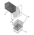
【図1】図1は、本発明の中空繊維配列体の製造方法模式図である。(1)は中空繊維配列体(樹脂で固定)、(2)は中空繊維(非固定)、(3)は生体高分子入り容器、及び(4)は連続面であることを示す。
【図2】図2は、本発明の中空繊維配列体の断面図の模式図である。
【図3】図3は、本発明の中空繊維配列体を、繊維軸に対して垂直方向にスライスして得られた生体高分子配列薄片の模式図である。[0001]
BACKGROUND OF THE INVENTION
The present invention relates to a method for producing a polymer material on which biopolymers such as nucleic acids, proteins, and polysaccharides that can be used in fields such as clinical tests and food tests are immobilized. Specifically, the present invention relates to a method for producing a biopolymer array flake in which the biopolymer using a hollow fiber or a porous hollow fiber is regularly arranged and fixed.
[0002]
[Prior art]
In recent years, genome projects in various organisms have been promoted, and many genes and their base sequences, including human genes, are being rapidly revealed. The function of a gene whose sequence has been clarified can be examined by various methods, and as one of the promising methods, gene expression analysis using the clarified nucleotide sequence information is known. For example, a method using various nucleic acid: nucleic acid hybridization reactions and various PCR reactions, as represented by Northern hybridization, has been developed, and the relationship between various genes and their biological function expression is examined by the method. Can do. However, these methods have limitations on the number of genes that can be applied. Therefore, comprehensive and systematic analysis of genes by the above method is performed from the viewpoint of the entire complex reaction system consisting of an extremely large number of genes at the individual level as revealed through today's genome project. It is difficult.
[0003]
Recently, a new analysis method or methodology called DNA microarray method (DNA chip method) that enables collective expression analysis of a large number of genes has been developed and attracts attention.
[0004]
These methods are in principle the same as conventional methods in that they are nucleic acid detection / quantification methods based on a nucleic acid: nucleic acid hybridization reaction, but a large number of planar substrates called microarrays or chips are used. A great feature is that DNA fragments are used which are aligned and fixed at high density. As a specific method of using the microarray method, for example, a sample obtained by labeling a gene expressed in a cell to be studied with a fluorescent dye or the like is hybridized on a flat substrate piece, and complementary nucleic acids (DNA or RNA) are bound to each other. There is a method in which the portion is labeled with a fluorescent dye or the like and then read at high speed with a high resolution analyzer. Thus, the amount of each gene in the sample can be quickly estimated. In other words, the essence of this new method is basically the integration of the reaction sample in a small amount and the technology that arranges and arranges the reaction sample in a reproducible, high-volume, rapid, and systematic form. It is understood that there is.
[0005]
As a technique for immobilizing a nucleic acid on a substrate, as in the Northern method, in addition to a method of immobilizing on a nylon sheet or the like at a high density, polylysine or the like on a substrate such as glass to further increase the density. A method of coating and immobilizing a nucleic acid, or a method of directly solid-phase synthesizing a short-chain nucleic acid on a substrate such as silicon has been developed.
[0006]
However, for example, a method of spotting and immobilizing a nucleic acid on a substrate obtained by chemically or physically modifying a solid surface such as glass [Science 270, 467-470 (1995)] is superior to the sheet method in spot density, It has been pointed out that the spot density and the amount of nucleic acid that can be immobilized per spot are small compared to the direct synthesis method on a silicon substrate (US Patent 5,445,934, US Patent 5,774,305) and are difficult to reproduce. On the other hand, with respect to a method of regularly and solid-phase synthesizing various short-chain nucleic acids in situ using photolithography technology on a substrate such as silicon, the number of nucleic acid species (spot density) that can be synthesized per unit area and Although the amount of immobilization per spot (synthesis amount) and reproducibility are superior to the spotting method, the types of compounds that can be immobilized are limited to relatively short-chain nucleic acids that can be controlled by photolithography. Furthermore, a large cost reduction per chip is difficult due to expensive manufacturing apparatuses and multi-stage manufacturing processes. In addition, a method using microbeads is known as a method for solid-phase synthesis of nucleic acids on a microcarrier to form a library. This method is capable of synthesizing various kinds of long-chain nucleic acids at a lower cost than the chip method, and it is considered that long-chain nucleic acids can be immobilized from cDNA or the like. However, unlike the chip method, it is difficult to produce a compound in which a specified compound is aligned with a specified sequence standard with good reproducibility.
[0007]
[Problems to be solved by the invention]
Under such circumstances, regardless of the size of the molecule, biopolymers such as nucleic acids, proteins, and polysaccharides can be immobilized at a predetermined concentration, and can be reproducibly arranged in a measurable form at high density. The establishment of a new systematic methodology that can be applied to inexpensive mass production is strongly required for gene analysis, which is expected to become increasingly important in the future.
[0008]
Specifically, the amount of biopolymer immobilization is higher than the method of producing biopolymer arrays by microspotting or microdispensing on a two-dimensional carrier such as a nylon sheet or glass substrate, and it is arranged per unit area. It is possible to increase the density of the molecular species of the biopolymer, which is more suitable for mass production, that is, a two-dimensional (planar) array in which the biopolymer is immobilized (two-dimensional array of immobilized biopolymers). The establishment of the manufacturing method of the body is a problem to be solved by the present invention.
[0009]
Further, the problem to be solved by the present invention is, for example, when the biopolymer is a nucleic acid, compared with a method for producing a high-density oligonucleic acid array by a combination of photolithography and solid phase synthesis on a silicon substrate. Is a method for producing an immobilized nucleic acid two-dimensional array that can be applied to a long-chain nucleic acid containing a lower production cost.
[0010]
An object of the present invention is to provide an efficient method for producing flakes in which biopolymers such as nucleic acids, proteins, polypeptides, and polysaccharides are regularly arranged and immobilized.
[0011]
[Means for Solving the Problems]
As a result of intensive studies to solve the above-mentioned problems, the present inventors have changed the idea of the conventional method in which the biopolymer alignment process and the immobilization process are performed on the same two-dimensional carrier. A three-dimensional structure in which biopolymers are aligned and arranged by creating a three-dimensional array of hollow fibers by fiber shaping technology, and efficiently introducing and immobilizing biopolymers into this array It was found that an immobilized biopolymer two-dimensional high-density array thin piece can be produced through a process of cutting and thinning the structure, and the present invention has been completed.
[0012]
That is, in the present invention, a plurality of hollow fibers are bundled to form an array, and then the biopolymer is immobilized on the inner wall portion and / or the hollow portion of each hollow fiber constituting the array, and then the biopolymer is fixed. A method for producing a biopolymer array slice characterized by slicing an immobilized array in a direction intersecting a fiber axis.
[0013]
The immobilization of the biopolymer to the inner wall portion and / or the hollow portion of each hollow fiber constituting the array is, for example, a liquid containing a biopolymer at the tip of the extended portion of each hollow fiber constituting the array. It can be carried out by immersing the solution in a hollow portion of each hollow fiber constituting the array.
[0014]
In the present invention, a plurality of porous hollow fibers are bundled to form an array, and then a biopolymer is immobilized on the inner wall portion, hollow portion and / or porous portion of each porous hollow fiber constituting the array body. And then slicing the biopolymer-immobilized array in a direction crossing the fiber axis.
[0015]
The immobilization of the biopolymer to the inner wall portion, the hollow portion and / or the porous portion of each porous hollow fiber constituting the array is, for example, an extension of each porous hollow fiber constituting the array. It can be carried out by immersing the tip in a liquid containing a biopolymer and introducing the liquid into the hollow part and / or the porous part of each porous hollow fiber constituting the array.
[0016]
The present invention also provides an arrayed body in which a plurality of hollow fibers are bundled to form an array, and then the hollow portion of each hollow fiber constituting the array is filled with a gel containing a biopolymer. Is sliced in a direction crossing the fiber axis.
[0017]
The hollow portion of each hollow fiber constituting the array is filled with the gel containing the biopolymer in the hollow portion, and the tip of the extended portion of each hollow fiber constituting the array is placed in the monomer solution containing the biopolymer. It can be carried out by immersing the substrate in a hollow portion and introducing the liquid into the hollow portion of each hollow fiber constituting the array, followed by polymerization to form a gel in the hollow portion.
[0018]
Furthermore, the present invention provides a gel containing a plurality of porous hollow fibers to form an array, and then a biopolymer in the inner wall, hollow and / or porous part of each porous hollow fiber constituting the array. And then slicing the biopolymer-immobilized array in a direction intersecting the fiber axis.
[0019]
Filling the hollow part and / or the porous wall part of the porous hollow fiber constituting the array with the gel containing the biopolymer with the tip of the extended portion of each porous hollow fiber constituting the array By immersing in a monomer solution containing a biopolymer, introducing the liquid into the hollow portion and / or porous portion of each porous hollow fiber constituting the array, and then polymerizing to form a gel in the hollow portion It can be carried out.
[0020]
As these arrays, for example, hollow fibers or porous hollow fibers regularly arranged, or a cross section of 1 cm perpendicular to the axial direction of the hollow fibers or porous hollow fibers constituting the array2Examples include those containing 100 or more hollow fibers or porous hollow fibers.
[0021]
In addition, examples of the biopolymer include a nucleic acid.
[0022]
The type of the nucleic acid may be different in all or a part of each hollow fiber or each porous hollow fiber constituting the array.
[0023]
DETAILED DESCRIPTION OF THE INVENTION
Hereinafter, the present invention will be described in detail.
[0024]
In the present invention, biopolymers to be immobilized on hollow fibers or porous hollow fibers include deoxyribonucleic acid (DNA), ribonucleic acid (RNA), peptide nucleic acid (PNA), and oxypeptide nucleic acid (OPNA). Examples include nucleic acids, proteins, polysaccharides, and the like. The biopolymer used in the present invention may be a commercially available product or may be obtained from living cells.
[0025]
For example, when nucleic acid is used as a biopolymer, DNA or RNA is prepared from living cells by a known method, for example, DNA extraction by the method of Blin et al. (Blin et al., Nucleic Acids Res. 3 : 2303 (1976)), and RNA can be extracted by the method of Favaloro et al. (Favaloro et al., Methods Enzymol. 65: 718 (1980)). Furthermore, linear or circular plasmid DNA or chromosomal DNA, DNA fragments obtained by digesting these with restriction enzymes or chemically, DNA synthesized by enzymes in a test tube, or chemically synthesized oligonucleotides, etc. should be used. You can also.
[0026]
In the present invention, the biopolymer may be immobilized as it is on a hollow fiber or the like, or a derivative obtained by chemically modifying the biopolymer or a modified biopolymer as necessary may be immobilized. .
[0027]
For example, when nucleic acid is used as a biopolymer, amination, biotinylation, digoxigenation and the like are known as chemical modification of nucleic acid [Current Protocols In Molecular Biology, Ed .; Frederick M. Ausubel et al. (1990), Deisotope Experiment Protocol (1) DIG Hybridization (Shyujunsha)], these modification methods can also be employed in the present invention.
[0028]
In the present invention, examples of hollow fibers that can be used for immobilizing biopolymers include synthetic fibers, semi-synthetic fibers, regenerated fibers, and natural fibers.
[0029]
Representative examples of synthetic fibers include various types of polyamide fibers such as nylon 6, nylon 66, and aromatic polyamide, various types of polyester fibers such as polyethylene terephthalate, polybutylene terephthalate, polylactic acid, and polyglycolic acid, and polyacrylonitrile. Various acrylic fibers, polyolefin fibers such as polyethylene and polypropylene, polyvinyl alcohol fibers, polyvinylidene chloride fibers, polyvinyl chloride fibers, polyurethane fibers, phenol fibers, polyfluoride Examples thereof include fluorine fibers made of vinylidene and polytetrafluoroethylene, and various fibers of polyalkylene paraoxybenzoate.
[0030]
Typical examples of semi-synthetic fibers include various cellulose-based derivative fibers made from diacetate, triacetate, chitin, chitosan, etc., and various protein-based fibers called promixes.
[0031]
Representative examples of the regenerated fiber include various cellulose-based regenerated fibers (rayon, cupra, polynosic, etc.) obtained by the viscose method, the copper-ammonia method, or the organic solvent method.
[0032]
Typical examples of natural fibers include flax, linseed, and jute. Since these plant fibers exhibit a hollow fiber form, they can be used in the present invention.
[0033]
Hollow fibers other than natural fibers can be produced by a known method using a special nozzle. Polyamide, polyester, polyolefin and the like are preferably melt-spun, and as the nozzle, a horseshoe type, C-type nozzle, double pipe nozzle, or the like can be used. In the present invention, it is preferable to use a double tube nozzle in that a continuous and uniform hollow portion can be formed.
[0034]
Solvent spinning is preferably used for spinning of synthetic polymers, semi-synthetic fibers or recycled fibers that cannot be melt-spun. Also in this case, a hollow fiber having a continuous hollow portion can be obtained by spinning using a double pipe nozzle as in the case of melt spinning while filling the hollow portion with an appropriate liquid as a core material.
[0035]
The form of the hollow fiber or porous hollow fiber used in the present invention is not particularly specified. Further, it may be a monofilament or a multifilament.
[0036]
The porous fiber used in the present invention can be obtained by combining a known spinning technique such as a drawing method, a microphase separation method, and an extraction method with a melt spinning method or a solution spinning method.
[0037]
The porosity of the porous fiber material used in the present invention is not particularly limited, but the specific surface area is increased from the viewpoint of increasing the density of the biopolymer immobilized around the fiber material unit length. A high porosity is desirable.
[0038]
Porous hollow fiber membranes for the purpose of microfiltration and ultrafiltration that are commercially available, reverse osmosis membranes in which the outer surface of porous hollow fiber membranes is coated with a nonporous homogeneous membrane, gas separation membranes, porous layers A film having a nonporous homogeneous layer sandwiched between them can be used.
[0039]
The hollow fiber or porous hollow fiber used in the present invention may be used as it is in an untreated state. However, if necessary, a reactive functional group may be introduced, and plasma treatment or γ may be used. It may be subjected to radiation treatment such as a wire or an electron beam.
[0040]
The array of the present invention has a structure in which hollow fibers or porous hollow fibers are regularly arranged and bonded with a resin adhesive or the like, for example, a tertiary fiber in which hollow fibers or porous hollow fibers are arranged regularly and regularly. An original array can be obtained. The shape of the three-dimensional array is not particularly limited, but it is usually formed into a square or a rectangle by regularly arranging fibers.
[0041]
“Regularly” means that the fibers are arranged in order so that the number of fibers contained in a frame of a certain size is constant. For example, in the case where fibers having a diameter of 1 mm are bundled and arranged so as to form a square having a cross section of 10 mm in length and 10 mm in width, the square frame (1 cm2The number of fibers contained in one side in 10) is 10, and the 10 fibers are bundled in one row to form a single layer sheet, and the sheets are stacked so as to form 10 layers. As a result, a total of 100 fibers can be arranged, 10 vertically and 10 horizontally. However, the method of regularly arranging the fibers is not limited to the method of stacking sheets as described above.
[0042]
In the present invention, the number of hollow fibers or porous hollow fibers to be a three-dimensional array is 100 or more, preferably 1,000 to 10,000,000, and can be appropriately set according to the purpose. . However, the fiber density in the array is 1 cm.2 It is preferable to prepare so that it may become 100-1,000,000 per. And in order to arrange | position a fiber in order to obtain the thin piece of the fiber array body by which the biopolymer was fix | immobilized with high density, the one where the thickness of a fiber is thin is preferable. In a preferred embodiment of the present invention, the cross section is 1 cm perpendicular to the direction of the fiber axis constituting the array.2 It contains 100 or more hollow fibers or porous hollow fibers. In order to achieve this, the outer diameter of one hollow fiber or porous hollow fiber needs to be 1 mm or less.
[0043]
For example, if a hollow fiber having an outer diameter of about 500 μm or a monofilament of porous hollow fiber is used, the cross section of the immobilized array is 1 cm.2A three-dimensional structure in which 400 or more hollow fibers or porous hollow fibers are arranged can be obtained. Further, by applying hollow fiber spinning technology, a hollow fiber or a porous hollow fiber having an outer diameter of about 30 μm is manufactured, and if this is used, the cross section of the immobilized array is 1 cm.2 It is possible to obtain a three-dimensional structure in which 100,000 or more hollow fibers or porous hollow fibers are arranged.
[0044]
In the present invention, an extension portion that is not fixed with resin to each hollow fiber or each porous hollow fiber constituting the array is provided, and the tip portion is immersed in a liquid tank containing a biopolymer, thereby Can be introduced into each fiber constituting the array.
[0045]
As a method for immobilizing a biopolymer to a hollow fiber or a porous hollow fiber, after introducing a liquid containing a biopolymer into the hollow portion of each hollow fiber or porous hollow fiber constituting the array, Various chemical or physical interactions between the inner wall surface of the porous hollow fiber and the biopolymer, that is, the functional group present on the inner wall surface of the hollow fiber or the porous hollow fiber and the biopolymer Chemical or physical interactions between the components to be made can be utilized.
[0046]
For example, when a nucleic acid modified with an amino group is used to be immobilized on a hollow fiber, the fiber is used with a crosslinking agent such as glutaraldehyde or 1-ethyl-3- (3-dimethylaminopropyl) carbodiimide (EDC). Can be combined with a functional group.
[0047]
In addition, the biopolymer can be immobilized on the hollow fiber or the like through the gel after the biopolymer is immobilized on the gel. The kind of gel that can be used here is not particularly limited. For example, acrylamide, N, N-dimethylacrylamide, N-isopropylacrylamide, N-acryloylaminoethoxyethanol, N-acryloylaminopropanol, N-methylol. Many types of monomers such as acrylamide, N-vinylpyrrolidone, hydroxyethyl methacrylate, (meth) acrylic acid, allyl dextrin, and the like, and methylene bis (meth) acrylamide, polyethylene glycol di (meth) acrylate, etc. Mention may be made of gels copolymerized with functional monomers.
[0048]
Immobilization in this case can be performed by introducing a solution containing the biopolymer, the monomer and the polymerization initiator into a hollow portion such as a hollow fiber and then polymerizing the solution.
[0049]
In addition to introducing a liquid containing a biopolymer by providing an extended portion that is not fixed to each hollow fiber or each porous hollow fiber constituting the array with a resin at one end, preferably at both ends. Various processes can be performed as necessary. For example, by performing heat treatment, alkali treatment, surfactant treatment, etc., the biopolymer immobilized on the inner wall surface of the hollow fiber or porous hollow fiber constituting the array is modified, or the cells, fungi When a biopolymer obtained from a biomaterial such as a body is used, unnecessary cell components can be removed. Note that these processes may be performed separately or simultaneously. Moreover, you may implement suitably before fixing the sample containing a biopolymer to the hollow fiber or porous hollow fiber which comprises an array.
[0050]
The types of biopolymers immobilized on each hollow fiber or porous hollow fiber in the three-dimensional array can be different types of biopolymers. That is, according to the present invention, the type and sequence of the immobilized biopolymer can be arbitrarily set according to the purpose.
[0051]
In the present invention, the cross-section of the arbitrarily arranged biopolymer-immobilized hollow fiber array or the living body is cut by cutting the three-dimensional array in a direction intersecting the fiber axis, preferably in a direction perpendicular to the fiber axis. A thin piece having a cross section of the polymer-immobilized porous hollow fiber array, that is, a biopolymer array thin piece can be obtained. As a cutting method at this time, for example, a method of cutting a slice from an array using a microtome, or the like can be mentioned. Although it can adjust arbitrarily regarding the thickness of a flake, it is 1-5,000 micrometers normally, Preferably it is 10-2,000 micrometers.
[0052]
The obtained biopolymer-immobilized hollow fiber array cross-section or biopolymer-immobilized porous hollow fiber array cross-section is a thin piece (biopolymer array flake) having a hollow fiber or a porous material constituting the array. There are biopolymers depending on the number of hollow fibers. Regarding the number of biopolymers per cross-sectional area of the flakes, by appropriately selecting the outer diameter of the hollow fiber or porous hollow fiber used, the cross-sectional area of the flakes is 1 cm.2It is possible to produce a flake on which 100 or more biopolymers are immobilized, and the cross-sectional area of the flake is 1 cm.2It is also possible to produce a thin piece on which 1000 or more biopolymers are immobilized.
[0053]
Further, since the position sequences of the biopolymers of the slices obtained from the same array are all the same, the position arrangement of the biopolymers of all the slices obtained from the same array is known.
[0054]
The obtained biopolymer-immobilized hollow fiber array cross-section or biopolymer-immobilized porous hollow fiber array cross-section, that is, biopolymer array flake, for example, the immobilized biopolymer is a nucleic acid In this case, the nucleic acid can be used as a probe to detect a base sequence of a specific polynucleotide in a sample by reacting with the sample and performing hybridization.
[0055]
The probe referred to in the present invention broadly refers to a fixed-side biopolymer that can specifically bind to a sample-sample-side biopolymer such as a protein or a low-molecular compound present in the sample. Therefore, the use of these flakes is not limited to the detection of the specimen-sample-side biopolymer that forms a hybrid with the immobilized biopolymer (probe). The use for detecting various samples, such as a protein and a low molecular weight compound which specifically couple | bond, is mentioned.
[0056]
When the immobilized biopolymer is a nucleic acid, the biopolymer array slice according to the present invention is reacted with the sample to perform hybridization, and form a hybrid with the nucleic acid present in the sample complementary to the probe. By detecting this hybrid, the nucleic acid in the sample having the target base sequence can be detected.
[0057]
In the case of detecting the hybrid, a known means that can specifically recognize the hybrid can be used. For example, a label such as a fluorescent substance, a luminescent substance, or a radioisotope is allowed to act on a biopolymer in a specimen, and this label can be detected. There are no restrictions on the type of the labeled body and the method for introducing the labeled body, and various conventionally known means can be used.
[0058]
【Example】
The invention is illustrated in more detail by the following examples. However, the technical scope of the present invention is not limited by these examples.
[0059]
[Example 1]
Production of hollow fiber array (1):
1cm2Using two fiber guide plates with a total of 400 holes arranged in a regular square array, 20 in each direction, 4 in each direction. Nylon hollow fiber (outer diameter: about 300 μm, length: about 50 cm) 400 in each hole of the fiber guide plate A hollow fiber array was obtained by passing the book.
[0060]
The distance between the two fiber guide plates was 20 cm, and the space between them was fixed with polyurethane resin, thereby obtaining a hollow fiber array having portions not fixed with resin at both ends.
[0061]
[Example 2]
Production of hollow fiber array (2):
In place of the nylon hollow fiber, a polyethylene hollow fiber (outer diameter: about 300 μm, length: about 50 cm) whose inner surface is hydrophilized with a polyethylene-vinyl alcohol copolymer is used in the same manner as in Example 1. A hollow fiber array having portions not fixed with resin at both ends was obtained.
[0062]
Example 3
Production of porous hollow fiber array:
Implemented except that a polyethylene porous hollow fiber membrane MHF200TL (Mitsubishi Rayon Co., Ltd., outer diameter 290 μm, inner diameter 200 μm, length about 50 cm) having a non-porous intermediate layer was used instead of the nylon hollow fiber. The same procedure as in Example 1 was performed to obtain a porous hollow fiber array having portions not fixed with resin at both ends.
[0063]
Example 4
Inner surface treatment of hollow fiber (1):
Formic acid was introduced into the hollow portion of each hollow fiber constituting the hollow fiber array obtained in Example 1 from the fiber portion that was not fixed with one resin, and held for 1 minute. Next, a large amount of room temperature water was introduced into the hollow portion and washed sufficiently, followed by drying to pretreat the nylon hollow fiber.
[0064]
Example 5
Inner surface treatment of hollow fiber (2):
A nylon hollow fiber was pretreated in the same manner as in Example 4 except that a 10% ethanol solution of sulfuric acid was used instead of formic acid.
[0065]
[Reference Example 1]
Synthesis of oligonucleotides having an amino group at the 5 'end:
The following oligonucleotides (probe A and probe B) were synthesized.
[0066]
Probe A: GCGATCGAAACCTTGCTGTACGAGCGAGGGCTC (SEQ ID NO: 1)
Probe B: GATGAGGTGGAGGTCAGGGTTTGGGACAGCAG (SEQ ID NO: 2)
Oligonucleotides were synthesized using PE Biosystems' automated synthesizer DNA / RNA synthesizer (model 394), and each oligonucleotide was synthesized using Aminolink II (trade name) (Applied Biosystems) in the final step of DNA synthesis. NH at the 5 'end of the nucleotide2(CH2)6-Was introduced and used after general deprotection and purification.
[0067]
Example 6
Introduction and immobilization of biopolymer to hollow fiber array (1):
After the hollow fiber array produced in Example 1 was subjected to the inner surface treatment of each constituent hollow fiber in Example 4 or 5, an oligo having an amino group synthesized in Reference Example 1 was used as an example of a biopolymer. Nucleotides (probe A and probe B) were introduced into each hollow fiber constituting the hollow fiber array by the following method and immobilized.
[0068]
From one end of the hollow fiber array, a solution in which an oligonucleotide having an amino group synthesized in Reference Example 1 was added to a potassium phosphate solution buffer was introduced, and then kept at 20 ° C. overnight.
[0069]
Thereafter, the inside of the hollow fiber was washed with a potassium phosphate solution buffer, a potassium chloride solution, and water to obtain a nucleic acid-immobilized hollow fiber array in which the oligonucleotide was immobilized on the inner wall surface of the hollow fiber.
[0070]
At this time, the oligonucleotides of probe A and probe B were introduced and immobilized so that the sequence in the hollow fiber array was as shown in FIG.
[0071]
In FIG. 2, a white circle (◯) represents a hollow fiber in which the probe A is fixed inside, and a black circle (●) represents a hollow fiber in which the probe B is fixed inside.
[0072]
Example 7
Introduction and immobilization of biopolymer to hollow fiber array (2):
Using the hollow fiber array produced in Example 2, a nucleic acid-immobilized hollow fiber array in which oligonucleotides were immobilized on the inner wall surface of the hollow fiber was obtained in the same manner as in Example 6.
[0073]
Also in this case, the oligonucleotide sequences of the probe A and the probe B in the hollow fiber array are the same as in Example 6.
[0074]
Example 8
Introduction and immobilization of biopolymer to hollow fiber array (3):
As an example of the biopolymer, an aqueous solution having the following composition containing oligonucleotides (probe A and probe B) having an amino group synthesized in Reference Example 1 was prepared.
[0075]
Acrylamide 3.7 parts by mass
Methylene bisacrylamide 0.3 parts by mass
2,2'-Azobis (2-amidinopropane) dihydrochloride 0.1 parts by mass
Aminated oligonucleotide (probe A or probe B) 0.005 parts by mass
After injecting this solution into the hollow portion of the hollow fiber that was subjected to the inner surface treatment of each constituent hollow fiber according to Example 4 or 5 with respect to the hollow fiber array produced in Example 1, the inside was saturated with water vapor. The mixture was transferred to a sealed glass container and allowed to stand at 80 ° C. for 4 hours to carry out a polymerization reaction.
[0076]
As a result, a hollow fiber array body in which a gel on which an oligonucleotide (probe A or probe B) was immobilized was retained was obtained.
[0077]
The oligonucleotide sequences of probe A and probe B in the hollow fiber array are the same as in Example 6.
[0078]
Example 9
Introduction and immobilization of biopolymer to hollow fiber array (4):
An oligonucleotide (probe A or probe B) was obtained in the same manner as in Example 8 using the polyethylene hollow fiber array obtained by hydrophilizing the inner surface obtained in Example 2 instead of the nylon hollow fiber. As a result, a hollow fiber array body was obtained, in which the gel on which was fixed was retained.
[0079]
The oligonucleotide sequences of probe A and probe B in the hollow fiber array are the same as in Example 6.
Example 10
Introduction and immobilization of biopolymer to porous hollow fiber array (1):
Using the porous hollow fiber array produced in Example 3, a nucleic acid-immobilized porous hollow fiber array in which oligonucleotides were immobilized on the inner wall surface of the porous hollow fiber was obtained in the same manner as in Example 6. Obtained.
[0080]
Also in this case, the oligonucleotide sequences of the probe A and the probe B in the porous hollow fiber array are the same as in Example 6.
[0081]
Example 11
Introduction and immobilization of biopolymer to porous hollow fiber array (2):
Using the hollow hollow fiber array produced in Example 3, a porous hollow fiber array in which a gel on which an oligonucleotide (probe A or probe B) is immobilized is held in the same manner as in Example 8 Got the body.
[0082]
The oligonucleotide sequences of probe A and probe B in the hollow fiber array are the same as in Example 6.
Example 12
Preparation of biopolymer array slices:
The biopolymer-immobilized hollow fiber array obtained in Examples 6 to 9 and the biopolymer-immobilized porous hollow fiber array obtained in Examples 10 and 11 were perpendicular to each fiber axis. By using a microtome, slices were cut out to a thickness of about 100 μm to obtain biopolymer array slices in which a total of 400 oligonucleotides were arranged in a regular square shape, 20 in each length and width. (Figure 3)
[Reference Example 2]
Sample nucleic acid labeling:
As a sample nucleic acid model, an oligonucleotide (C, D) complementary to a part of the sequence of the oligonucleotide (probe A, probe B) synthesized in Reference Example 1 was synthesized.
[0083]
Oligonucleotide C: GAGCCCTCGCTCGTACAGCAAGGTTTCG (SEQ ID NO: 3)
Oligonucleotide D: CTGCTGTCCCAAACCCTGACCTCCACC (SEQ ID NO: 4)
In the same manner as in Reference Example 1, the 5 'ends of these oligonucleotides were NH-attached to the 5' end of each oligonucleotide using Aminolink II (trade name) (PE Biosystems Japan).2(CH2)6-Was introduced, and then labeled with digoxigenin (Roche Diagnostics Inc.) as follows.
[0084]
Each terminal-aminated oligonucleotide was dissolved in 100 mM borate buffer (pH 8.5) to a final concentration of 2 mM. An equal amount of Digoxigenin-3-O-methylcarbonyl-ε-aminocapronic acid-N-hydroxy-succinimide ester (26 mg / ml dimethylformamide solution) was added and allowed to stand overnight at room temperature.
[0085]
Adjust the volume to 100 μl, add 2 μl glycogen (Roche Diagnostics), 10 μl 3M sodium acetate (pH 5.2), 300 μl cold ethanol and collect the precipitate by centrifugation at 15,000 rpm for 15 minutes. did. 500 μl of 70% ethanol was added to the precipitate, and the precipitate was collected again at the bottom of the tube by centrifugation at 15,000 rpm for 5 minutes. The precipitate was air-dried and dissolved in 100 μl of 10 mM Tris-HCl (pH 7.5), 1 mM EDTA.
[0086]
The DIG-labeled oligonucleotide thus obtained was used as a sample nucleic acid model.
[0087]
[Reference Example 3]
Hybridization:
A biopolymer array slice in which each oligonucleotide prepared in Example 12 is regularly arranged in a square is placed in a hybridization bag, a hybridization solution having the following composition is poured, and prepolymerized at 45 ° C. for 30 minutes. Hybridization was performed.
[0088]
The DIG-labeled DNA obtained in Reference Example 2 was added, and hybridization was performed at 45 ° C. for 15 hours.
[0089]
Hybridization solution composition:
5 × SSC (0.75M sodium chloride, 0.075M sodium citrate, pH 7.0)
5% blocking reagent (Roche Diagnostics Inc.)
0.1% N-lauroyl sarcosine sodium
0.02% SDS (sodium lauryl sulfate)
50% formamide
[Reference Example 4]
detection:
After completion of hybridization, the biopolymer array slices on which the oligonucleotides were regularly arranged in a square were transferred to a 50 ml of 0.1 × SSC, 0.1% SDS solution that had been kept warm for 20 minutes while shaking. Washing was performed 3 times at 45 ° C.
[0090]
[0091]
After removing the moisture, it was transferred to a new hybridization bag and left at 37 ° C. for 1 hour. Then, the film was sandwiched with an X-ray film binder together with the X-ray film to expose the film.
[0092]
As a result, it was confirmed that in any of the biopolymer array slices, the oligonucleotide C was bound to the place where the probe A was placed, and the oligonucleotide D was bound to the place where the probe B was placed. It was done.
[0093]
DIG buffer 1: 0.1 M maleic acid, 0.15 M sodium chloride (pH 7.5)
DIG buffer 2:
DIG buffer 3: 0.1 M Tris-hydrochloric acid (pH 9.5), 0.1 M sodium chloride, 0.05 M magnesium chloride
Blocking reagent: Anti-DIG alkaline phosphatase labeled antibody solution and AMPPD are reagents in the DIG Detection Kit (Roche Diagnostics Inc.).
[0094]
【The invention's effect】
According to the present invention, a thin section having a fiber cross section of a biopolymer-immobilized hollow fiber array or a porous hollow fiber array in which biopolymers are arbitrarily arranged with high density and accuracy, that is, a biopolymer array section is obtained. It can be obtained efficiently with good reproducibility. Using this biopolymer array slice, the type and amount of biopolymer in the specimen can be examined.
[0095]
[Sequence Listing]
[Free text of sequence listing]
SEQ ID NO: 1 synthetic DNA
Sequence number 2: Synthetic DNA
Sequence number 3: Synthetic DNA
Sequence number 4: Synthetic DNA
[Brief description of the drawings]
FIG. 1 is a schematic diagram of a method for producing a hollow fiber array according to the present invention. (1) indicates a hollow fiber array (fixed with resin), (2) indicates a hollow fiber (non-fixed), (3) indicates a biopolymer-containing container, and (4) indicates a continuous surface.
FIG. 2 is a schematic view of a cross-sectional view of the hollow fiber array of the present invention.
FIG. 3 is a schematic view of a biopolymer array slice obtained by slicing the hollow fiber array of the present invention in a direction perpendicular to the fiber axis.
Claims (1)
(1)中空繊維又は多孔質中空繊維を複数本束ねて、配列体とする工程。
(2)各繊維の中空部に、生体高分子、重合性モノマーを含む溶液を導入する工程。
(3)中空部内で重合反応を行い、中空部にゲルを保持する工程。
(4)配列体を繊維軸と交叉する方向にスライスする工程。A method for producing a biopolymer array flake, comprising sequentially performing the following steps.
(1) A step of bundling a plurality of hollow fibers or porous hollow fibers to form an array.
(2) A step of introducing a solution containing a biopolymer and a polymerizable monomer into the hollow portion of each fiber.
(3) A step of performing a polymerization reaction in the hollow portion and holding the gel in the hollow portion.
(4) A step of slicing the array in the direction crossing the fiber axis.
Priority Applications (1)
| Application Number | Priority Date | Filing Date | Title |
|---|---|---|---|
| JP2000250943A JP4404328B2 (en) | 1999-08-26 | 2000-08-22 | Method for producing biopolymer array flake |
Applications Claiming Priority (3)
| Application Number | Priority Date | Filing Date | Title |
|---|---|---|---|
| JP24004199 | 1999-08-26 | ||
| JP11-240041 | 1999-08-26 | ||
| JP2000250943A JP4404328B2 (en) | 1999-08-26 | 2000-08-22 | Method for producing biopolymer array flake |
Publications (3)
| Publication Number | Publication Date |
|---|---|
| JP2001133453A JP2001133453A (en) | 2001-05-18 |
| JP2001133453A5 JP2001133453A5 (en) | 2007-10-04 |
| JP4404328B2 true JP4404328B2 (en) | 2010-01-27 |
Family
ID=26534556
Family Applications (1)
| Application Number | Title | Priority Date | Filing Date |
|---|---|---|---|
| JP2000250943A Expired - Lifetime JP4404328B2 (en) | 1999-08-26 | 2000-08-22 | Method for producing biopolymer array flake |
Country Status (1)
| Country | Link |
|---|---|
| JP (1) | JP4404328B2 (en) |
Families Citing this family (12)
| Publication number | Priority date | Publication date | Assignee | Title |
|---|---|---|---|---|
| JP2003014741A (en) * | 2001-05-25 | 2003-01-15 | Akihiro Fujimura | Method of manufacturing mosaic reagent, and so on, and its product and manufacturing device |
| CN100471776C (en) * | 2003-05-19 | 2009-03-25 | 三菱丽阳株式会社 | Yarn arrangement device and method for yarn arrangement using the device, yarn arrangement tool, method of manufacturing yarn arranged body, and method of manufacturing living body-related substance i |
| CN103975053A (en) * | 2011-12-01 | 2014-08-06 | 三菱丽阳株式会社 | Base for use in amplification of nucleic acid, and nucleic acid amplification method |
| JP2013179884A (en) * | 2012-03-01 | 2013-09-12 | Mitsubishi Rayon Co Ltd | Nucleic acid microarray for evaluating component relating to melanin cascade and method for evaluating component relating to melanin cascade |
| EP2832863A4 (en) | 2012-03-29 | 2016-02-24 | Mitsubishi Rayon Co | Microarray for detection of mutations in beta-globin genes and detection method thereof |
| JP6094481B2 (en) | 2012-05-02 | 2017-03-15 | 三菱レイヨン株式会社 | Probe or probe set and nucleic acid microarray for evaluating the influence of ultraviolet rays on the skin |
| JP2014052204A (en) * | 2012-09-05 | 2014-03-20 | Mitsubishi Rayon Co Ltd | Microarray for detecting biological related substances, manufacturing method therefor, and method for detecting biological related substances |
| US20160024582A1 (en) | 2013-04-08 | 2016-01-28 | Mitsubishi Rayon Co., Ltd. | Microarray for evaluating eye disease, and evaluation method of eye disease |
| WO2015079998A1 (en) | 2013-11-29 | 2015-06-04 | 三菱レイヨン株式会社 | Biochip holder, method for manufacturing biochip holder, biochip retainer, and biochip-holder kit |
| JP6959021B2 (en) | 2017-03-14 | 2021-11-02 | 株式会社ジーシー | DNA chip for detecting caries bacteria |
| CN111542617A (en) | 2017-11-02 | 2020-08-14 | 三菱化学株式会社 | Method for estimating inflammatory area of periodontal pocket |
| CA3084012A1 (en) | 2017-11-02 | 2019-05-09 | Mitsubishi Chemical Corporation | Intraoral examination method using information on bacterial group related to clinical indexes |
-
2000
- 2000-08-22 JP JP2000250943A patent/JP4404328B2/en not_active Expired - Lifetime
Also Published As
| Publication number | Publication date |
|---|---|
| JP2001133453A (en) | 2001-05-18 |
Similar Documents
| Publication | Publication Date | Title |
|---|---|---|
| US6875620B1 (en) | Tiling process for constructing a chemical array | |
| KR100538502B1 (en) | Carriers Having Biological Substance | |
| US8802369B2 (en) | Gel having biosubstance fixed thereto and microarray utilizing the gel | |
| JP4404328B2 (en) | Method for producing biopolymer array flake | |
| JP3883539B2 (en) | Method for producing hydrogel biochip using radial polyethylene glycol derivative having epoxy group | |
| JP2000245460A (en) | Nucleic acid-immobilized hollow fiber and arranged body of nucleic acid-immobilized hollow fibers and its thin specimen | |
| JP2001108683A (en) | Dna fragment fixing solid-phase carrier, dna fragment fixing method, and nucleic-acid fragment detecting method | |
| JP2000270878A (en) | Nucleic acid-immobilized gel-holding hollow fiber, arranged body of the hollow fiber and section thereof | |
| JP4108891B2 (en) | Nucleic acid-immobilized gel-carrying porous hollow fiber, porous hollow fiber array and thin piece thereof | |
| JP2000270879A (en) | Nucleic acid-immobilized gel-holding fiber, arranged body of the fiber and section thereof | |
| JP2000245461A (en) | Nucleic acid-immobilized hollow fiber and arranged body of nucleic acid-immobilized hollow fiber and its thin layer | |
| JP2000270877A (en) | Nucleic acid-immobilized gel-holding porous fiber, arranged body of the porous fiber and section thereof | |
| JP2001136968A (en) | Biopolymer-immobilized film laminate and thin film thereof, and method for producing them | |
| JP2000279177A (en) | Porous fiber in which nucleic acid was fixed, porous fiber array in which nucleic acid was fixed, and thin slice thereof | |
| JP4036611B2 (en) | Bio-related substance microarray and detection method using the same | |
| JP2011133470A (en) | Biomolecule immobilization array having biomolecule immobilization carrier consisting of hydrophilic gel | |
| JP2000325082A (en) | Laminate of nucleic acid immobilized film and its slice | |
| JP2000325083A (en) | Laminate of film holding nucleic acid immobilized gel and its slice | |
| JP2010259340A (en) | Through-hole microarray and method for producing the same | |
| JP3515470B2 (en) | Manufacturing method of fiber array | |
| JP2001122892A (en) | Nucleic acid immobilized polymer gel and method for producing the gel | |
| JP2001136972A (en) | Nucleic acid-fixed polymer gel and production method | |
| JP2004066829A (en) | Manufacturing method for fiber arrangement | |
| JP2002022739A (en) | Living organism related substance immobilization micro- array | |
| JP5394045B2 (en) | Method for detecting mouse Acidicribosomal Phosphoprotein P0 gene |
Legal Events
| Date | Code | Title | Description |
|---|---|---|---|
| A521 | Written amendment |
Free format text: JAPANESE INTERMEDIATE CODE: A523 Effective date: 20070816 |
|
| A621 | Written request for application examination |
Free format text: JAPANESE INTERMEDIATE CODE: A621 Effective date: 20070816 |
|
| A977 | Report on retrieval |
Free format text: JAPANESE INTERMEDIATE CODE: A971007 Effective date: 20091022 |
|
| TRDD | Decision of grant or rejection written | ||
| A01 | Written decision to grant a patent or to grant a registration (utility model) |
Free format text: JAPANESE INTERMEDIATE CODE: A01 Effective date: 20091029 |
|
| A01 | Written decision to grant a patent or to grant a registration (utility model) |
Free format text: JAPANESE INTERMEDIATE CODE: A01 |
|
| A61 | First payment of annual fees (during grant procedure) |
Free format text: JAPANESE INTERMEDIATE CODE: A61 Effective date: 20091030 |
|
| FPAY | Renewal fee payment (event date is renewal date of database) |
Free format text: PAYMENT UNTIL: 20121113 Year of fee payment: 3 |
|
| R151 | Written notification of patent or utility model registration |
Ref document number: 4404328 Country of ref document: JP Free format text: JAPANESE INTERMEDIATE CODE: R151 |
|
| FPAY | Renewal fee payment (event date is renewal date of database) |
Free format text: PAYMENT UNTIL: 20121113 Year of fee payment: 3 |
|
| FPAY | Renewal fee payment (event date is renewal date of database) |
Free format text: PAYMENT UNTIL: 20121113 Year of fee payment: 3 |
|
| S531 | Written request for registration of change of domicile |
Free format text: JAPANESE INTERMEDIATE CODE: R313531 |
|
| FPAY | Renewal fee payment (event date is renewal date of database) |
Free format text: PAYMENT UNTIL: 20121113 Year of fee payment: 3 |
|
| R350 | Written notification of registration of transfer |
Free format text: JAPANESE INTERMEDIATE CODE: R350 |
|
| FPAY | Renewal fee payment (event date is renewal date of database) |
Free format text: PAYMENT UNTIL: 20121113 Year of fee payment: 3 |
|
| FPAY | Renewal fee payment (event date is renewal date of database) |
Free format text: PAYMENT UNTIL: 20131113 Year of fee payment: 4 |
|
| R250 | Receipt of annual fees |
Free format text: JAPANESE INTERMEDIATE CODE: R250 |
|
| R250 | Receipt of annual fees |
Free format text: JAPANESE INTERMEDIATE CODE: R250 |
|
| R250 | Receipt of annual fees |
Free format text: JAPANESE INTERMEDIATE CODE: R250 |
|
| R250 | Receipt of annual fees |
Free format text: JAPANESE INTERMEDIATE CODE: R250 |
|
| S533 | Written request for registration of change of name |
Free format text: JAPANESE INTERMEDIATE CODE: R313533 |
|
| R250 | Receipt of annual fees |
Free format text: JAPANESE INTERMEDIATE CODE: R250 |
|
| R350 | Written notification of registration of transfer |
Free format text: JAPANESE INTERMEDIATE CODE: R350 |
|
| R250 | Receipt of annual fees |
Free format text: JAPANESE INTERMEDIATE CODE: R250 |
|
| R250 | Receipt of annual fees |
Free format text: JAPANESE INTERMEDIATE CODE: R250 |
|
| EXPY | Cancellation because of completion of term |