JP4399228B2 - Weft insertion control device in jet loom - Google Patents
Weft insertion control device in jet loom Download PDFInfo
- Publication number
- JP4399228B2 JP4399228B2 JP2003349475A JP2003349475A JP4399228B2 JP 4399228 B2 JP4399228 B2 JP 4399228B2 JP 2003349475 A JP2003349475 A JP 2003349475A JP 2003349475 A JP2003349475 A JP 2003349475A JP 4399228 B2 JP4399228 B2 JP 4399228B2
- Authority
- JP
- Japan
- Prior art keywords
- weft
- weft insertion
- arrival time
- control
- injection
- Prior art date
- Legal status (The legal status is an assumption and is not a legal conclusion. Google has not performed a legal analysis and makes no representation as to the accuracy of the status listed.)
- Expired - Fee Related
Links
Images


Classifications
-
- D—TEXTILES; PAPER
- D03—WEAVING
- D03D—WOVEN FABRICS; METHODS OF WEAVING; LOOMS
- D03D47/00—Looms in which bulk supply of weft does not pass through shed, e.g. shuttleless looms, gripper shuttle looms, dummy shuttle looms
- D03D47/28—Looms in which bulk supply of weft does not pass through shed, e.g. shuttleless looms, gripper shuttle looms, dummy shuttle looms wherein the weft itself is projected into the shed
- D03D47/30—Looms in which bulk supply of weft does not pass through shed, e.g. shuttleless looms, gripper shuttle looms, dummy shuttle looms wherein the weft itself is projected into the shed by gas jet
- D03D47/3026—Air supply systems
- D03D47/3053—Arrangements or lay out of air supply systems
-
- D—TEXTILES; PAPER
- D03—WEAVING
- D03D—WOVEN FABRICS; METHODS OF WEAVING; LOOMS
- D03D47/00—Looms in which bulk supply of weft does not pass through shed, e.g. shuttleless looms, gripper shuttle looms, dummy shuttle looms
- D03D47/28—Looms in which bulk supply of weft does not pass through shed, e.g. shuttleless looms, gripper shuttle looms, dummy shuttle looms wherein the weft itself is projected into the shed
- D03D47/30—Looms in which bulk supply of weft does not pass through shed, e.g. shuttleless looms, gripper shuttle looms, dummy shuttle looms wherein the weft itself is projected into the shed by gas jet
- D03D47/3026—Air supply systems
- D03D47/3033—Controlling the air supply
- D03D47/304—Controlling of the air supply to the auxiliary nozzles
Description
本発明は、エア噴射作用によって緯糸を緯入れする緯入れ用ノズルと、前記緯入れ用ノズルに圧力エアを供給するタイミングを変更可能な開閉弁とを備えたジェットルームにおける緯入れ制御装置に関するものである。 The present invention relates to a weft insertion control device in a jet loom comprising a weft insertion nozzle for weft insertion by air injection action, and an on-off valve capable of changing the timing for supplying pressure air to the weft insertion nozzle. It is.
緯入れ用メインノズル及び緯入れ用補助ノズルのエア噴射作用によって緯糸を緯入れするジェットルームでは、緯入れ末端側における緯糸の到達時期を適正に制御することが織布品質の確保の上で重要である。そのため、特許文献1に開示の緯入れ制御装置では、緯入れ途中経過角度を検出し、この検出結果に基づいて緯入れ用メインノズルの噴射終了時の圧力波形を変更制御するようにしている。又、特許文献2に開示の緯入れ制御方法では、高圧空気の経路と低圧空気の経路との共同で、緯入れノズルから圧力空気を噴射するようにしている。そして、検出された緯糸到達時期と標準の緯糸到達時期との偏差に基づいて、次回以降の緯入れ時に、高圧空気噴射期間及び低圧緯入れ開始時期を前記偏差の解消方向に変更するようにしている。
特許文献1に開示の装置では、緯入れ途中経過角度を検出している緯入れ時に圧力波形を変更制御しようとしている。しかし、緯入れ途中経過角度の検出及びこの検出結果に応じた圧力波形の変更制御を共に短い緯入れ期間内に行なうのは、極めて困難である。つまり、圧力波形の変更制御が間に合わない。
In the apparatus disclosed in
特許文献2に開示の制御方法では、緯糸到達時期を検出した緯入れ時よりも後の緯入れ時に、高圧空気噴射期間及び低圧緯入れ開始時期を前記偏差の解消方向に変更するようにしているので、制御が間に合わないという問題は回避できる。
In the control method disclosed in
しかし、検出された単一の緯糸到達時期のみに基づいて次回以降の緯入れ時の高圧空気噴射期間及び低圧緯入れ開始時期の制御を行なう方法では、検出される緯糸到達時期を標準の緯糸到達時期に適切に収束させることは難しい。 However, in the method of controlling the high-pressure air injection period and the low-pressure weft insertion start timing at the next and subsequent weft insertions based only on the detected single weft arrival timing, the detected weft arrival timing is set as the standard weft arrival timing. It is difficult to properly converge on the time.
本発明は、緯糸到達時期を目標の緯糸到達時期に適切に収束させることを目的とする。 An object of the present invention is to appropriately converge the weft arrival time to the target weft arrival time.
そのために本発明は、エア噴射作用によって緯糸を緯入れする緯入れ用ノズルと、前記緯入れ用ノズルに圧力エアを供給するタイミングを変更可能な開閉弁とを備えたジェットルームを対象とし、請求項1の発明では、緯糸到達時期を検出する緯糸到達時期検出手段と、前記緯糸到達時期検出手段によって検出された複数の緯糸到達時期の平均値と予め設定された目標到達時期との差に基づいて、前記緯入れ用ノズルから噴射されるエアの噴射状態を制御する噴射状態制御手段と、前記緯糸到達時期検出手段によって検出された単一の緯糸到達時期と前記目標到達時期との差に基づいて、次回の緯入れ時に前記開閉弁の開閉タイミングを制御する噴射タイミング制御手段とを備え、前記噴射タイミング制御手段は、検出された単一の緯糸到達時期が前記目標到達時期よりも所定期間以上遅れたときに、次回の緯入れ時に前記開閉弁の閉タイミングを遅らせる遅延制御を行なうとともに、前記遅延制御開始後、検出された単一の緯糸到達時期と前記目標到達時期との差が前記所定期間より小さい状態となった場合に、次々回の緯入れ時以降で前記開閉弁の閉タイミングの遅延量を少なくしながら前記遅延制御が開始される前の閉タイミングに戻るまで前記遅延制御を継続する緯入れ制御装置を構成した。
To this end, the present invention is directed to a jet loom including a weft insertion nozzle for weft insertion by air injection and a switching valve capable of changing the timing for supplying pressure air to the weft insertion nozzle. In the invention of
ここにおける開閉弁の開閉タイミングを制御するとは、開タイミングのみを制御、閉タイミングのみを制御、又は開タイミングと閉タイミングとの両方を制御することを意味する。 Controlling the opening / closing timing of the opening / closing valve here means controlling only the opening timing, controlling only the closing timing, or controlling both the opening timing and the closing timing.
検出された複数の緯糸到達時期の平均値と予め設定された目標到達時期との差に基づく噴射状態の制御は、緯糸到達時期の緩慢な変動に対処するのに適している。検出された単一の緯糸到達時期と前記目標到達時期との差に基づく開閉弁の開閉タイミング制御(つまり、噴射タイミング制御)は、緯糸到達時期が緯糸の太さや毛羽立ち等のムラによって突発的に大きく変動する場合に対処するのに適している。複数の緯糸到達時期の平均値を用いた噴射状態の制御と、単一の緯糸到達時期を用いた開閉タイミング制御との組み合わせは、緯糸到達時期を目標の緯糸到達時期に適切に収束させるのに有効である。 Control of the injection state based on the difference between the detected average value of the plurality of weft arrival times and a preset target arrival time is suitable for dealing with slow fluctuations in the weft arrival times. The on-off valve opening / closing timing control (that is, injection timing control) based on the difference between the detected single weft arrival time and the target arrival time is that the weft arrival time is suddenly caused by unevenness such as the weft thickness or fluffing. Suitable for dealing with large fluctuations. The combination of the injection state control using the average value of multiple weft arrival times and the opening / closing timing control using a single weft arrival time makes it possible to properly converge the weft arrival time to the target weft arrival time. It is valid.
また、緯糸到達時期が大きく遅れると、緯糸緩みが生じやすい。次回の緯入れ時には開閉弁の閉タイミングが遅らせられるので、緯糸到達時期の遅れが低減される。 Further, if the weft arrival time is greatly delayed, weft loosening is likely to occur. Since the closing timing of the on-off valve is delayed at the next weft insertion, the delay in the weft arrival time is reduced .
次々回の緯入れ時以降で前記開閉弁の閉タイミングの遅延量を少なくしてゆく制御は、緯糸到達時期が目標到達時期から遅れる方向に変動してしまうおそれを回避するのに有効である。 Control that reduces the delay amount of the closing timing of the on-off valve after the next weft insertion is effective in avoiding the possibility that the weft arrival time will fluctuate in a direction that is delayed from the target arrival time.
請求項2の発明では、請求項1において、前記噴射状態制御手段は、緯入れ用ノズルから噴射されるエアの圧力、緯入れ用ノズルから噴射されるエアの流量、又は前記開閉弁の開閉タイミングのいずれか1つを制御するものとした。 According to a second aspect of the present invention, in the first aspect , the injection state control means is configured such that the pressure of air injected from the weft insertion nozzle, the flow rate of air injected from the weft insertion nozzle, or the opening / closing timing of the on-off valve Any one of these was controlled.
検出された複数の緯糸到達時期の平均値と予め設定された目標到達時期との差に基づくエア圧力、エア流量又は開閉タイミングのいずれか1つの制御は、緩慢な緯糸到達時期の変動に対処するのに適している。 Any one of the control of the air pressure, the air flow rate and the opening / closing timing based on the difference between the detected average value of the plurality of weft arrival times and a preset target arrival time copes with the slow fluctuation of the weft arrival time. Suitable for
本発明は、緯糸到達時期を目標の緯糸到達時期に適切に収束させられるという優れた効果を奏する。 The present invention has an excellent effect that the weft arrival time can be appropriately converged to the target weft arrival time.
以下、本発明を具体化した一実施形態を図1〜図3に基づいて説明する。
11は巻付方式の緯糸測長貯留装置であり、緯糸測長貯留装置11の糸巻付面111上への糸巻付け及び糸巻付面111からの緯糸引き出し解舒は、電磁ソレノイド12の係止ピン121の出没動作によって制御される。電磁ソレノイド12の励消磁は、制御コンピュータCの指令制御によって行われ、制御コンピュータCは、緯糸解舒検出器13からの緯糸解舒検出情報に基づいて電磁ソレノイド12の励消磁を制御する。緯糸解舒検出器13は、糸巻付面111上の巻き糸の解舒を検出する。
DESCRIPTION OF EMBODIMENTS Hereinafter, an embodiment embodying the present invention will be described with reference to FIGS.
Reference numeral 11 denotes a winding type weft length measuring and storing device. The winding of the weft length measuring and storing device 11 onto the
緯入れ用メインノズル14の噴射作用によって糸巻付面111から引き出し射出された緯糸Yは、複数の緯入れ用補助ノズル群15,16,17,18のリレー噴射へと受け継がれる。緯入れが良好に行われた場合には所定の機台回転角度範囲にて緯糸Yが緯糸検出器19によって検出される。緯糸検出器19からの緯糸有無検出信号は制御コンピュータCに入力され、制御コンピュータCは、緯糸有無検出信号に基づいて織機の運転継続及び停止のいずれかを選択する。
The weft Y drawn and ejected from the
緯入れ用ノズルとしての緯入れ用メインノズル14における緯入れ用圧力エア噴射は、電磁開閉弁20の開閉により制御される。緯入れ用ノズルとしての緯入れ用補助ノズル群15〜18における緯入れ用圧力エア噴射は、電磁開閉弁21,22,23,24の開閉により制御される。電磁開閉弁20は、圧力エア供給タンク25に接続されており、電磁開閉弁21,22,23,24は、圧力エア供給タンク26に接続されている。電磁開閉弁20〜24は、緯入れ用ノズルに圧力エアを供給するタイミングを変更可能な開閉弁である。
The weft insertion pressure air injection in the weft insertion
各電磁開閉弁20〜24の開閉制御は、制御コンピュータCからの指令により行われる。制御コンピュータCは、織機回転角度検出用のロータリーエンコーダ30から得られる織機回転角度検出信号に基づいて電磁開閉弁20〜24の開閉を制御する。
Open / close control of each of the electromagnetic open /
各圧力エア供給タンク25,26は、電気式の圧力制御弁27,28を介して元圧タンク29に接続されている。圧力制御弁27は、圧力エア供給タンク25の圧力を調整するためのものであり、圧力制御弁28は、圧力エア供給タンク26の圧力を調整するためのものである。
Each of the pressure
図2(a),(b),(c)は、電磁開閉弁20〜24の開閉タイミング、つまり緯入れ用メインノズル14及び緯入れ用補助ノズル群15〜18における噴射タイミングを示すタイミングチャートを表す。横軸は時間Tを表し、縦軸は緯入れされた緯糸の先端到達位置(緯入れ位置)を表す。横軸は、織機1回転(クランク角度360°の範囲)の一部の角度範囲を時間表示に置換したものである。
2A, 2B, and 2C are timing charts showing the opening / closing timings of the electromagnetic opening / closing valves 20-24, that is, the injection timings of the weft insertion
曲線Mは、緯入れ用メインノズル14の噴射タイミングを表し、曲線E1,E2,E3,E4は、緯入れ用補助ノズル群15〜18の噴射タイミングを表す。時期Toは、糸巻付面111上の巻糸を係止ピン121の係止作用から解放開始する時、即ち電磁ソレノイド12の励磁開始時期を表す。時期M1は、緯入れ用メインノズル14用の電磁開閉弁20及び緯入れ用補助ノズル群15用の電磁開閉弁21における開タイミングを表す。時期E2s,E3s,E4sは、緯入れ用補助ノズル群16〜18用の電磁開閉弁22〜24における開タイミングを表す。電磁開閉弁20〜24における開タイミングE2s,E3s,E4sは、固定されている。時期M2は、緯入れ用メインノズル14用の電磁開閉弁20における閉タイミングを表し、時期E1e,E2e,E3e,E4eは、緯入れ用補助ノズル群15〜18用の電磁開閉弁21〜24における閉タイミングを表す。以下においては、E1e,E2e,E3e,E4eをEje(j=1,2,3,4)と表すこともある。
The curve M represents the injection timing of the weft insertion
噴射タイミング曲線M,E1〜E4の閉タイミングE1e,E2e,E3e,E4eは、予め設定された基準閉タイミングにしてある。図2(a)における線D1及び図2(b)における線D2は、緯糸Yの飛走状態の一例を示す。 The closing timings E1e, E2e, E3e, and E4e of the injection timing curves M and E1 to E4 are set to preset reference closing timings. A line D1 in FIG. 2A and a line D2 in FIG. 2B show an example of the flying state of the weft Y.
圧力エア供給タンク25,26には圧力検出器31,32が接続されており、圧力検出器31,32によって得られる圧力検出情報は、制御コンピュータCに入力される。制御コンピュータCは、圧力検出器31,32からの圧力情報に基づいて圧力制御弁27,28をフィードバック制御する。
制御コンピュータCは、緯糸検出器19から得られる緯糸検出信号と、ロータリーエンコーダ30から得られる織機回転角度検出信号とに基づいて、緯糸到達時期を検出する。緯糸検出器19、ロータリーエンコーダ30及び制御コンピュータCは、緯糸が緯入れ末端側(つまり、緯糸検出器19の検出領域)に到達する時期を検出する緯糸到達時期検出手段を構成する。制御コンピュータCは、検出された緯糸到達時期に基づいて、圧力制御弁27,28の駆動制御を行なって圧力エア供給タンク25,26の圧力を制御する。制御コンピュータCは、即ち緯入れ用メインノズル14及び緯入れ用補助ノズル群15〜18における噴射圧制御を行なう。
The control computer C detects the weft arrival time based on the weft detection signal obtained from the
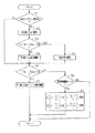
図3は、噴射圧制御及び噴射タイミング制御を行なうための緯入れ制御プログラムを表すフローチャートである。以下、図3のフローチャートで示す緯入れ制御を説明する。
制御コンピュータCは、緯糸検出器19から得られる緯糸到達時期TWのサンプリング数が所定数N(例えば、N=50)に達したか否かを判断している(ステップS1)。緯糸到達時期TWのサンプリング数が所定数Nに達した場合(ステップS1においてYES)、制御コンピュータCは、この所定数の緯糸到達時期TWの平均値〈TW〉を算出する(ステップS2)。つまり、平均値〈TW〉の算出は、緯入れN回毎に1回行われる。制御コンピュータCは、緯糸Yの目標到達時期TWoと検出された緯糸到達時期の平均値〈TW〉との差(TWo−〈TW〉)の絶対値と許容差α(>0)との大小関係を判断する(ステップS3)。
FIG. 3 is a flowchart showing a weft insertion control program for performing injection pressure control and injection timing control. Hereinafter, weft insertion control shown in the flowchart of FIG. 3 will be described.
The control computer C determines whether or not the sampling number of the weft arrival time TW obtained from the
差(TWo−〈TW〉)の絶対値が許容差α以下である場合(ステップS3においてYES)、制御コンピュータCは、緯入れ用メインノズル14における噴射圧及び緯入れ用補助ノズル群15〜18における噴射圧を現状の圧力に維持する(ステップS4)。差(TWo−〈TW〉)の絶対値が許容差αを越える場合(ステップS3においてNO)、制御コンピュータCは、差(TWo−〈TW〉)の絶対値が許容差α内に収束する方向に、緯入れ用メインノズル14及び緯入れ用補助ノズル群15〜18における噴射圧の変更制御を行なう(ステップS5)。(〈TW〉−TWo)>αの場合、即ち緯糸到達が遅過ぎる場合には、制御コンピュータCは、緯入れ用メインノズル14及び緯入れ用補助ノズル群15〜18における噴射圧を高めるように、圧力制御弁27,28の圧力調整状態を変更する。(〈TW〉−TWo)<−αの場合、即ち緯糸到達が早過ぎる場合には、制御コンピュータCは、緯入れ用メインノズル14及び緯入れ用補助ノズル群15〜18における噴射圧を下げるように、圧力制御弁27,28の圧力調整状態を変更する。
When the absolute value of the difference (TWo− <TW>) is equal to or smaller than the tolerance α (YES in step S3), the control computer C determines the injection pressure and the weft insertion
ステップS1においてNOの場合(単一の緯糸到達時期TWのサンプリング数が所定数Nに達していない場合)、又は、ステップS4,S5の後、制御コンピュータCは、差(TW−TWo)と予め設定された閾値β(>α)との大小関係を判断する(ステップS6)。この緯入れ時〔P(1)と表す〕において検出された差(TW−TWo)が閾値β以上である場合(ステップS6においてYES)、制御コンピュータCは、次回の緯入れ時〔P(2)と表す〕における電磁開閉弁20〜24の閉タイミングを遅延させる制御を行なう(S7)。
In the case of NO in step S1 (when the sampling number of the single weft arrival time TW has not reached the predetermined number N), or after steps S4 and S5, the control computer C preliminarily calculates the difference (TW−TWo). The magnitude relation with the set threshold value β (> α) is determined (step S6). When the difference (TW−TWo) detected at the time of weft insertion [denoted as P (1)] is equal to or larger than the threshold value β (YES in step S6), the control computer C performs the next weft insertion [P (2 The control for delaying the closing timing of the electromagnetic open /
βの値は、制御コンピュータCに信号接続された入力装置33(図1に図示)によって任意に入力設定可能である。
図2(b)は、緯入れ用メインノズル14及び緯入れ用補助ノズル群15〜18における噴射タイミングを示すタイミングチャートを表す。図2(b)における噴射タイミングは、図2(a)の場合と同じにしてある。線D2は、差(TW−TWo)が閾値β以上である緯糸Yの飛走状態の一例を示す。
The value of β can be arbitrarily set by an input device 33 (shown in FIG. 1) connected in signal to the control computer C.
FIG. 2B shows a timing chart showing injection timings in the weft insertion
ステップS7における遅延制御では、例えば電磁開閉弁20における閉タイミングが差(TW−TWo)だけ遅延され、電磁開閉弁21〜23における閉タイミングが差(TW−TWo)の2倍だけ遅延される。図2(c)は、図2(b)の噴射タイミングに対する制御後の緯入れ用メインノズル14及び緯入れ用補助ノズル群15〜18における噴射タイミングを示すタイミングチャートを表す。図2(c)は、電磁開閉弁20における閉タイミングを差(TW−TWo)だけ遅延し、電磁開閉弁21〜23における閉タイミングを差(TW−TWo)の2倍だけ遅延した場合の例を示す。
In the delay control in step S7, for example, the closing timing of the electromagnetic opening / closing
ステップS6においてNOの場合、即ち緯入れ時P(1)において検出された差(TW−TWo)が閾値βよりも小さい場合、制御コンピュータCは、今回の緯入れ時P(1)が遅延制御継続モードであるか否かを判断する(ステップS8)。 If NO in step S6, that is, if the difference (TW−TWo) detected in the weft insertion P (1) is smaller than the threshold value β, the control computer C performs delay control during the current weft insertion P (1). It is determined whether or not the continuous mode is set (step S8).
制御コンピュータCは、ステップS7で制御された次回の緯入れ時P(2)において差(TW−TWo)が閾値βに達しない状態となった場合にも、制御コンピュータCは、次々回の緯入れ時〔P(3)と表す〕以降の所定回の緯入れ時において遅延制御を継続する。 Even when the difference (TW−TWo) does not reach the threshold value β in the next weft insertion P (2) controlled in step S7, the control computer C does not repeat the next weft insertion. The delay control is continued at a predetermined time after the time [denoted as P (3)].
図2(c)の場合を例にとって遅延制御の継続を説明する。電磁開閉弁20の閉タイミングの遅延量〔つまり、(TW−TWo)〕をγ、電磁開閉弁21〜23における閉タイミングの遅延量〔つまり、2×(TW−TWo)〕をδとする。制御コンピュータCは、次々回の緯入れ時P(3)における電磁開閉弁20の閉タイミングを〔M2+γ(1―1/n)〕に変更し、次々回の緯入れ時P(3)における電磁開閉弁21〜23の閉タイミングを〔Eje+δ(1―1/n)〕に変更する。nは、2以上の整数である。
The continuation of delay control will be described by taking the case of FIG. 2C as an example. Assume that the delay amount [that is, (TW−TWo)] of the electromagnetic on-off
例えば、nが2の場合には、次々回の緯入れ時P(3)には、電磁開閉弁20の閉タイミングは、〔M2+γ/2〕となり、電磁開閉弁21〜23の閉タイミングは、〔Eje+δ/2〕となる。つまり、この場合の次々回の緯入れ時は、遅延制御継続モードである。そして、次々回の緯入れ時P(3)の次の緯入れ時〔P(4)と表す〕には、電磁開閉弁20の閉タイミングは、M2となり、電磁開閉弁21〜23の閉タイミングは、Ejeとなる。つまり、この場合の次々回の緯入れ時P(3)次の緯入れ時P(4)は、遅延制御継続モードではない。
For example, when n is 2, the closing timing of the electromagnetic on / off
nが3の場合には、次々回の緯入れ時P(3)には、電磁開閉弁20の閉タイミングは、〔M2+γ×2/3〕となり、電磁開閉弁21〜23の閉タイミングは、〔Eje+δ×2/3〕となる。つまり、この場合の次々回の緯入れ時P(3)は、遅延制御継続モードである。次々回の緯入れ時P(3)の次の緯入れ時P(4)には、電磁開閉弁20の閉タイミングは、〔M2+γ/3〕となり、電磁開閉弁21〜23の閉タイミングは、〔Eje+δ/3〕となる。つまり、この場合の次々回の緯入れ時P(3)の次の緯入れ時P(4)は、遅延制御継続モードである。そして、次回の緯入れ時P(2)から3回後の緯入れ時〔P(5)と表す〕には、電磁開閉弁20の閉タイミングは、M2となり、電磁開閉弁21〜23の閉タイミングは、Ejeとなる。つまり、この場合の次回の緯入れ時P(2)から3回後の緯入れ時P(5)は、遅延制御継続モードではない。
When n is 3, the closing timing of the electromagnetic on-off
ステップS8においてYESの場合(つまり、遅延制御継続モードである場合)、制御コンピュータCは、γ(1−k/n)をγ〔1−(k+1)/n〕に変更する(ステップS9)。kは、0<k<nの整数である。nが2の場合には、kは1であり、nが3の場合には、kは1,2である。つまり、ステップS9は、遅延制御継続又は遅延制御継続停止を表している。 If YES in step S8 (that is, in the delay control continuation mode), the control computer C changes γ (1-k / n) to γ [1- (k + 1) / n] (step S9). k is an integer of 0 <k <n. When n is 2, k is 1, and when n is 3, k is 1 and 2. That is, step S9 represents delay control continuation or delay control continuation stop.
nの値は、入力装置33によって任意に入力設定可能である。
以上のような制御を行なう制御コンピュータCは、検出された複数の緯糸到達時期TWの平均値〈TW〉と予め設定された目標到達時期TWoとの差に基づいて、緯入れ用ノズルから噴射されるエアの噴射状態(本実施形態では、圧力エア供給タンク25,26におけるエア圧力)を制御する噴射状態制御手段である。又、制御コンピュータCは、検出された単一の緯糸到達時期TWと目標到達時期TWoとの差に基づいて、次回の緯入れ時P(2)に開閉弁の開閉タイミング(本実施形態では閉タイミング)を制御する噴射タイミング制御手段である。制御コンピュータCによって圧力調整状態を変更される圧力制御弁27,28は、緯入れ用ノズルから噴射されるエアの噴射状態を調整するためのエア噴射調整手段である。
The value of n can be arbitrarily set by the
The control computer C that performs the control as described above is ejected from the weft insertion nozzle based on the difference between the detected average value <TW> of the plurality of weft arrival times TW and a preset target arrival time TWo. This is an injection state control means for controlling the air injection state (in this embodiment, the air pressure in the pressure
本実施形態では以下の効果が得られる。
(1−1)制御コンピュータCは、検出された複数の緯糸到達時期の平均値〈TW〉と目標到達時期TWoとの差に基づいて、圧力エア供給タンク25,26における圧力を制御する。つまり、制御コンピュータCは、検出された複数の緯糸到達時期の平均値〈TW〉と目標到達時期TWoとの差に基づいて、緯入れ用メインノズル14及び緯入れ用補助ノズル群15〜18における噴射圧力(噴射されるエアの噴射状態)を制御する。検出された複数の緯糸到達時期の平均値〈TW〉と予め設定された目標到達時期TWoとの差に基づく噴射圧力の制御(以下、平均値制御ということにする)は、緩慢な緯糸到達時期の変動に対処するのに適している。
In the present embodiment, the following effects can be obtained.
(1-1) The control computer C controls the pressure in the pressure
又、制御コンピュータCは、緯入れ時P(1)において検出された単一の緯糸到達時期TWと目標到達時期TWoとの差に基づいて、次回の緯入れ時P(2)に電磁開閉弁20〜24の開閉タイミング(本実施形態では閉タイミングのみ)を制御する。検出された単一の緯糸到達時期TWと目標到達時期TWoとの差に基づく電磁開閉弁20〜24の開閉タイミング制御(以下、リアルタイム制御ということにする)は、緯糸到達時期が緯糸の太さや毛羽立ち等のムラによって突発的に大きく変動する場合に対処するのに適している。
Further, the control computer C uses the electromagnetic on-off valve at the next weft insertion P (2) based on the difference between the single weft arrival time TW detected at the weft insertion P (1) and the target arrival time TWo. The opening /
例えば、平均値制御のみを行なう従来の緯入れ制御では、緯糸到達時期が突発的に大きく変動した次の緯入れ時以降における噴射圧力を迅速に適正制御できない(つまり、圧力制御が遅れる)ため、緯糸到達時期の突発的な大きな変動を迅速に収束させることができない。 For example, in the conventional weft insertion control in which only the average value control is performed, the injection pressure after the next weft insertion time when the weft arrival time suddenly fluctuates greatly cannot be controlled promptly (that is, the pressure control is delayed). The sudden large fluctuation in the weft arrival time cannot be quickly converged.
制御コンピュータCは、平均値制御と、リアルタイム制御とを組み合わせた緯入れ制御を行なう。そのため、緯糸到達時期が突発的に大きく遅れた緯入れ時P(1)の次の緯入れ時P(2)には、緯糸測長貯留装置11及び緯入れ用補助ノズル群15〜18におけるエア噴射期間が長くなるので、次回の緯入れ時P(2)には緯糸到達時期の大きな遅れを抑制することができる。従って、複数の緯糸到達時期TWの平均値〈TW〉を用いた噴射状態の制御(平均値制御)と、単一の緯糸到達時期TWを用いた開閉タイミング制御(リアルタイム制御)との組み合わせは、緯糸到達時期を目標の緯糸到達時期に適切に収束させるのに有効である。
The control computer C performs weft insertion control combining average value control and real-time control. Therefore, at the weft insertion time P (2) after the weft insertion time P (1) when the weft arrival time is suddenly greatly delayed, the air in the weft length measuring storage device 11 and the weft insertion
(1−2)緯糸到達時期が大きく遅れると、緯糸緩みが生じやすい。緯糸到達時期が大きく遅れたとき〔つまり、緯糸到達時期が(TWo+β)以後になること〕には、次回の緯入れ時P(2)には電磁開閉弁20〜24の閉タイミングが遅延されるので、緯糸到達時期の遅れを抑制して緯糸緩みの発生を防止することができる。
(1-2) When the weft arrival time is greatly delayed, weft loosening is likely to occur. When the weft arrival time is greatly delayed (that is, the weft arrival time is after (TWo + β)), the closing timing of the electromagnetic on-off
(1−3)制御コンピュータCは、緯糸到達時期が大きく遅れた緯入れ時P(1)の次の緯入れ時P(2)に電磁開閉弁20〜24の閉タイミングを遅らせる制御を行なう。このような遅延制御を行なった場合には、次々回の緯入れ時P(3)〔つまり、緯糸到達時期が大きく遅れた緯入れ時P(1)の次の次の緯入れ時〕以降で電磁開閉弁20〜24の閉タイミングの遅延量を少なくしてゆく制御を行なう。
(1-3) The control computer C performs control to delay the closing timing of the electromagnetic on-off
電磁開閉弁20〜24の閉タイミングを遅らせる制御を行なった緯入れ時〔つまり、緯糸到達時期が大きく遅れた緯入れ時P(1)の次の緯入れ時P(2)〕において、検出された緯糸到達時期の遅れが所定期間(つまり、閾値β)よりも小さくなったとする。このような場合に、次々回の緯入れ時P(3)における電磁開閉弁20〜24の閉タイミングの遅延量を零にしてしまうと、緯糸到達時期が目標到達時期TWoから遅れる方向に変動してしまうおそれがある。次々回の緯入れ時以降で電磁開閉弁20〜24の閉タイミングの遅延量を少なくしてゆく制御は、緯糸到達時期が目標到達時期TWoから遅れる方向に変動してしまうおそれを回避するのに有効である。
Detected at the time of weft insertion in which the closing timing of the electromagnetic open /
本発明では以下のような実施形態も可能である。
(1)前記した実施形態では、緯入れ用ノズルから噴射されるエアの噴射状態として噴射圧力(つまり、圧力エア供給タンク25,26におけるエア圧力)を用いたが、エアの噴射状態としてエア流量を用いてもよい。この場合には、電磁開閉弁20と圧力エア供給タンク25との間の流路に電気式の流量制御弁を介在し、電磁開閉弁21〜24と圧力エア供給タンク26との間に電気式の流量制御弁を介在すればよい。そして、検出された複数の緯糸到達時期の平均値と予め設定された目標到達時期との差に基づいて、この差を解消する方向に、流量制御弁の流量調整状態を変更するように制御すればよい。
In the present invention, the following embodiments are also possible.
(1) In the above-described embodiment, the injection pressure (that is, the air pressure in the pressure
(2)エアの噴射状態として開閉弁の開閉タイミングを用いてもよい。この場合には、検出された複数の緯糸到達時期の平均値と予め設定された目標到達時期との差に基づいて、この差を解消する方向に、開閉弁の開閉タイミングを変更するように制御すればよい。 (2) The opening / closing timing of the on-off valve may be used as the air injection state. In this case, based on the difference between the detected average value of the plurality of weft arrival times and the preset target arrival time, control is performed to change the opening / closing timing of the on-off valve in a direction to eliminate this difference. do it.
(3)緯糸到達検出手段として緯糸解舒検出器13を用いてもよい。
(4)リアルタイム制御において、開閉弁の開閉タイミングを制御する場合には、開タイミングと閉タイミングとの両方を制御するようにしてもよい。
(3) The
(4) In real-time control, when controlling the opening / closing timing of the opening / closing valve, both the opening timing and the closing timing may be controlled.
(5)リアルタイム制御において、開閉弁の開閉タイミングを制御する場合には、開タイミングのみを制御するようにしてもよい。
(6)リアルタイム制御では、緯入れ用補助ノズル群15〜18用の電磁開閉弁21〜24の開閉タイミングのみを制御するようにしてもよい。
(5) In the real-time control, when controlling the opening / closing timing of the opening / closing valve, only the opening timing may be controlled.
(6) In the real-time control, only the opening / closing timings of the electromagnetic opening /
(7)リアルタイム制御では、緯入れ用補助ノズル群15〜18用の電磁開閉弁21〜24のうちの一部の開閉タイミングのみを制御するようにしてもよい。
(8)リアルタイム制御では、緯入れ用メインノズル14用の電磁開閉弁20の開閉タイミングのみを制御するようにしてもよい。
(7) In the real-time control, only a part of the opening / closing timings of the electromagnetic opening /
(8) In real-time control, only the opening / closing timing of the electromagnetic opening / closing
(9)平均値制御では、緯入れ用補助ノズル群15〜18における噴射圧力(つまり、圧力エア供給タンク26におけるエア圧力)のみを制御するようにしてもよい。
(10)リアルタイム制御において、図3のフローチャートにおけるステップS8,S9を遂行しないようにしてもよい。つまり、(TW−TWo)≧βのときには、次回の緯入れ時においてのみ閉タイミングを遅延させるようにしてもよい。
(9) In the average value control, only the injection pressure in the weft insertion
(10) In real-time control, steps S8 and S9 in the flowchart of FIG. 3 may not be performed. That is, when (TW−TWo) ≧ β, the closing timing may be delayed only at the next weft insertion.
(11)例えば、2β>(TW−TWo)≧βの場合には、図3のステップS9におけるnを2とし、(TW−TWo)≧2βの場合には、図3のステップS9におけるnを3とするように、差(TW−TWo)の大きさに応じて、nの値を変化させるようにしてもよい。 (11) For example, when 2β> (TW−TWo) ≧ β, n in step S9 in FIG. 3 is set to 2, and when (TW−TWo) ≧ 2β, n in step S9 in FIG. 3, the value of n may be changed in accordance with the magnitude of the difference (TW−TWo).
(12)平均値制御では、サンプリングN個のうちの最古の検出された緯糸到達時期の代わりに、新たに検出された緯糸到達時期を採用してゆく移動平均値を用いてもよい。
前記した実施形態から把握できる技術的思想について以下に記載する。
(12) In the average value control, instead of the earliest detected weft arrival time among the N samples, a moving average value that adopts a newly detected weft arrival time may be used.
The technical idea that can be grasped from the embodiment described above will be described below.
〔1〕エア噴射作用によって緯糸を緯入れする緯入れ用ノズルと、前記緯入れ用ノズルに圧力エアを供給するタイミングを変更可能な開閉弁とを備えたジェットルームにおいて、
緯糸が緯入れ末端側に到達する時期を検出し、検出された複数の緯糸到達時期の平均値を用いて、検出される緯糸到達時期と予め設定された目標到達時期との差を解消する方向に、前記緯入れ用ノズルから噴射されるエアの噴射状態を制御し、検出された単一の緯糸到達時期を用いて予め設定された目標到達時期との差を解消する方向に、次の緯入れ時に前記開閉弁の開閉タイミングを制御するジェットルームにおける緯入れ制御方法。
[1] In a jet loom comprising a weft insertion nozzle for weft insertion by air injection action, and an on-off valve capable of changing the timing of supplying pressure air to the weft insertion nozzle,
A direction in which the time when the weft reaches the weft insertion end side is detected, and the difference between the detected weft arrival time and a preset target arrival time is eliminated by using the average value of the plurality of detected weft arrival times Next, in the direction of controlling the injection state of the air injected from the weft insertion nozzle and eliminating the difference from the preset target arrival time using the detected single weft arrival time, the next weft A weft insertion control method in a jet loom for controlling the opening / closing timing of the on-off valve at the time of insertion.
〔2〕前記緯入れ用ノズルから噴射されるエアの噴射状態を調整するためのエア噴射調整手段を備え、前記噴射状態制御手段は、前記エア噴射調整手段における調整状態を制御するジェットルームにおける緯入れ制御装置。 [2] an air jetting means for adjusting the injection state of the air ejected from the weft insertion nozzle, the injection state control means, in distearate Ettorumu to control the adjustment state in said air injection adjusting means Weft insertion control device.
〔3〕前記緯糸到達時期検出手段は、緯入れ末端側の所定位置における緯糸の有無を検出する緯糸検出器を含むジェットルームにおける緯入れ制御装置。 [3] the weft arrival timing detecting means, weft insertion control apparatus in including plain Ettorumu the weft detector for detecting the presence or absence of the weft yarn at a predetermined position of the weft insertion terminal side.
14…緯入れ用ノズルとしての緯入れ用メインノズル。15〜18…緯入れ用ノズルとしての緯入れ用補助ノズル群。19…緯糸到達検出手段を構成する緯糸検出器。20〜24…開閉弁としての電磁開閉弁。25,26…エア噴射状態調整手段としての圧力制御弁。C…噴射状態制御手段及び噴射タイミング制御手段としての制御コンピュータ。Y…緯糸。TW…緯糸到達時期。〈TW〉…平均値。TWo…目標到達時期。E1e,E2e,E3e,E4e…閉タイミング。差…TW−TWo。β…所定期間としての閾値。 14 ... Main nozzle for weft insertion as a nozzle for weft insertion. 15 to 18: Weft insertion auxiliary nozzle groups as nozzles for weft insertion. 19: Weft detector constituting weft arrival detection means. 20 to 24: Electromagnetic on-off valves as on-off valves. 25, 26 ... Pressure control valves as air injection state adjusting means. C: Control computer as injection state control means and injection timing control means. Y ... Weft. TW ... Weft arrival time. <TW> ... Average value. TWo ... Target achievement time. E1e, E2e, E3e, E4e ... close timing. Difference ... TW-TWo. β is a threshold value as a predetermined period.
Claims (2)
緯糸到達時期を検出する緯糸到達時期検出手段と、
前記緯糸到達時期検出手段によって検出された複数の緯糸到達時期の平均値と予め設定された目標到達時期との差に基づいて、前記緯入れ用ノズルから噴射されるエアの噴射状態を制御する噴射状態制御手段と、
前記緯糸到達時期検出手段によって検出された単一の緯糸到達時期と前記目標到達時期との差に基づいて、次回の緯入れ時に前記開閉弁の開閉タイミングを制御する噴射タイミング制御手段とを備え、
前記噴射タイミング制御手段は、検出された単一の緯糸到達時期が前記目標到達時期よりも所定期間以上遅れたときに、次回の緯入れ時に前記開閉弁の閉タイミングを遅らせる遅延制御を行なうとともに、
前記遅延制御開始後、検出された単一の緯糸到達時期と前記目標到達時期との差が前記所定期間より小さい状態となった場合に、次々回の緯入れ時以降で前記開閉弁の閉タイミングの遅延量を少なくしながら前記遅延制御が開始される前の閉タイミングに戻るまで前記遅延制御を継続するジェットルームにおける緯入れ制御装置。 In a jet loom comprising a weft insertion nozzle for weft insertion by air injection action, and an on-off valve capable of changing the timing of supplying pressure air to the weft insertion nozzle,
Weft arrival time detection means for detecting the weft arrival time;
Injection for controlling an injection state of air injected from the weft insertion nozzle based on a difference between an average value of a plurality of weft arrival times detected by the weft arrival time detection means and a preset target arrival time State control means;
Injection timing control means for controlling the opening / closing timing of the on-off valve at the next weft insertion based on the difference between the single weft arrival time detected by the weft arrival time detection means and the target arrival time;
The injection timing control means performs delay control to delay the closing timing of the on-off valve at the next weft insertion when the detected single weft arrival time is delayed by a predetermined period or more from the target arrival time,
After the start of the delay control, when the difference between the detected single weft arrival time and the target arrival time is smaller than the predetermined period, the closing timing of the on-off valve is changed after the next weft insertion. A weft insertion control device in a jet loom that continues the delay control until returning to the closing timing before the delay control is started while reducing the delay amount.
Priority Applications (3)
| Application Number | Priority Date | Filing Date | Title |
|---|---|---|---|
| JP2003349475A JP4399228B2 (en) | 2003-10-08 | 2003-10-08 | Weft insertion control device in jet loom |
| BE2004/0492A BE1016322A3 (en) | 2003-10-08 | 2004-10-07 | Control device in a jet loom for insert woof thread. |
| CN200410083565.7A CN1605669B (en) | 2003-10-08 | 2004-10-08 | Filling insertion controlling device of jet loom |
Applications Claiming Priority (1)
| Application Number | Priority Date | Filing Date | Title |
|---|---|---|---|
| JP2003349475A JP4399228B2 (en) | 2003-10-08 | 2003-10-08 | Weft insertion control device in jet loom |
Publications (2)
| Publication Number | Publication Date |
|---|---|
| JP2005113319A JP2005113319A (en) | 2005-04-28 |
| JP4399228B2 true JP4399228B2 (en) | 2010-01-13 |
Family
ID=34541330
Family Applications (1)
| Application Number | Title | Priority Date | Filing Date |
|---|---|---|---|
| JP2003349475A Expired - Fee Related JP4399228B2 (en) | 2003-10-08 | 2003-10-08 | Weft insertion control device in jet loom |
Country Status (3)
| Country | Link |
|---|---|
| JP (1) | JP4399228B2 (en) |
| CN (1) | CN1605669B (en) |
| BE (1) | BE1016322A3 (en) |
Families Citing this family (13)
| Publication number | Priority date | Publication date | Assignee | Title |
|---|---|---|---|---|
| WO2007057217A1 (en) | 2005-11-21 | 2007-05-24 | Picanol N.V. | Method for introducing a weft thread in an air weaving machine and air weaving machine |
| BE1016857A3 (en) * | 2005-11-21 | 2007-08-07 | Picanol Nv | Introducing method for weft thread in an air weaving machine by determining an instant when the supply of compressed air to one set of auxiliary blowers is interrupted to control measurements on the transported weft thread |
| JP5098299B2 (en) * | 2006-11-03 | 2012-12-12 | 株式会社豊田自動織機 | Abnormality detection method for flow control valve of air jet loom |
| EP2319968B1 (en) * | 2009-11-09 | 2013-01-02 | ITEMA S.p.A. | Air control system for inserting a weft yarn in a pneumatic weaving loom |
| CN102268772B (en) * | 2011-07-13 | 2013-08-21 | 中达电通股份有限公司 | Automatic air-jet loom weft insertion control system and method |
| JP5958296B2 (en) * | 2012-11-16 | 2016-07-27 | 株式会社豊田自動織機 | Compressed air flow rate display device for air jet loom |
| JP6190250B2 (en) * | 2013-11-14 | 2017-08-30 | 株式会社豊田自動織機 | Weft detection device for air jet loom |
| CN104894731A (en) * | 2015-03-12 | 2015-09-09 | 天津工业大学 | Air jet loom weft insertion air flow pressure flow measurement system |
| CN106012243B (en) * | 2015-03-27 | 2017-08-25 | 株式会社丰田自动织机 | Weft examining device for air-jet loom |
| JP6447533B2 (en) * | 2016-02-19 | 2019-01-09 | 株式会社豊田自動織機 | Weft insertion control method and weft insertion control apparatus for air jet loom |
| JP6994377B2 (en) * | 2017-12-13 | 2022-01-14 | 株式会社豊田自動織機 | Weaving diagnostic method for air jet looms |
| JP7388322B2 (en) * | 2020-09-07 | 2023-11-29 | 株式会社豊田自動織機 | Air jet loom weft insertion device |
| CN113011854A (en) * | 2021-03-29 | 2021-06-22 | 广东溢达纺织有限公司 | Method and device for determining matching result of warp yarns and weft yarns and computer equipment |
Family Cites Families (7)
| Publication number | Priority date | Publication date | Assignee | Title |
|---|---|---|---|---|
| JP2715078B2 (en) * | 1987-09-11 | 1998-02-16 | 津田駒工業株式会社 | Horizontal insertion control device |
| SE9002892D0 (en) * | 1990-09-10 | 1990-09-10 | Iro Ab | MANAGED EXTENSION BRAKE AT FURNITURE FOR TEXTILE MACHINERY, PREPARATION WIRE OF AIR OR WATER JET TYPE |
| JP2898773B2 (en) * | 1991-03-08 | 1999-06-02 | 津田駒工業株式会社 | Jet loom weft insertion control device |
| JPH0559638A (en) * | 1991-08-29 | 1993-03-09 | Toyota Central Res & Dev Lab Inc | Controller for picking in jet loom |
| JPH09228192A (en) * | 1996-02-14 | 1997-09-02 | Tsudakoma Corp | Control of picking |
| JP3608306B2 (en) * | 1996-09-19 | 2005-01-12 | 株式会社豊田自動織機 | Injecting action adjustment instruction device in jet loom |
| JPH10102353A (en) * | 1996-09-26 | 1998-04-21 | Micron Kk | Weft-controlling apparatus in loom |
-
2003
- 2003-10-08 JP JP2003349475A patent/JP4399228B2/en not_active Expired - Fee Related
-
2004
- 2004-10-07 BE BE2004/0492A patent/BE1016322A3/en not_active IP Right Cessation
- 2004-10-08 CN CN200410083565.7A patent/CN1605669B/en not_active Expired - Fee Related
Also Published As
| Publication number | Publication date |
|---|---|
| CN1605669A (en) | 2005-04-13 |
| JP2005113319A (en) | 2005-04-28 |
| CN1605669B (en) | 2010-11-10 |
| BE1016322A3 (en) | 2006-08-01 |
Similar Documents
| Publication | Publication Date | Title |
|---|---|---|
| JP4399228B2 (en) | Weft insertion control device in jet loom | |
| JP5423597B2 (en) | Weft insertion state discrimination device and weft insertion control device in jet loom | |
| JP2010001591A (en) | Method and apparatus for weft insertion in jet loom | |
| JP4804703B2 (en) | Weft insertion control method for loom | |
| JP2849422B2 (en) | Method and apparatus for controlling injection pressure of weft insertion nozzle of loom | |
| JP2701545B2 (en) | Pressure controller for weft insertion in jet loom | |
| US5107902A (en) | Method for controlling weft thread insertion timing in an air jet loom | |
| CN109629088B (en) | Weft insertion device of air jet loom and automatic adjustment method thereof | |
| JP2012117201A (en) | Weft insertion device in jet loom | |
| JP2004052171A (en) | Method for controlling weft inserting in air-jet loom | |
| JPH09228192A (en) | Control of picking | |
| JPH0382846A (en) | Picking-controlling device in loom | |
| JP2792128B2 (en) | Weft insertion control method in jet loom | |
| JP2671514B2 (en) | Weft insertion control device in multicolor jet loom | |
| JPH0693534A (en) | Apparatus for controlling weft-insertion in jet loom | |
| JPH1096140A (en) | Regulating and indicating device for jetting actions in jet loom | |
| EP3567143B1 (en) | Method of controlling weft insertion of air jet loom | |
| JP3289359B2 (en) | Loom driving method and apparatus | |
| JP2687529B2 (en) | Weft insertion control method in jet loom | |
| JP2636467B2 (en) | Weft insertion control device in jet loom | |
| JP2712243B2 (en) | Weft insertion method in shet room | |
| JPH06257034A (en) | Weft-insertion controlling apparatus for jet loom | |
| JPH0816298B2 (en) | Weft insertion control device in jet loom | |
| JP3669605B2 (en) | Sub nozzle injection control method | |
| JP2003213545A (en) | Air-injection unit in loom |
Legal Events
| Date | Code | Title | Description |
|---|---|---|---|
| A621 | Written request for application examination |
Free format text: JAPANESE INTERMEDIATE CODE: A621 Effective date: 20051018 |
|
| A977 | Report on retrieval |
Free format text: JAPANESE INTERMEDIATE CODE: A971007 Effective date: 20070403 |
|
| A131 | Notification of reasons for refusal |
Free format text: JAPANESE INTERMEDIATE CODE: A131 Effective date: 20070807 |
|
| A521 | Request for written amendment filed |
Free format text: JAPANESE INTERMEDIATE CODE: A523 Effective date: 20070928 |
|
| A02 | Decision of refusal |
Free format text: JAPANESE INTERMEDIATE CODE: A02 Effective date: 20071113 |
|
| A521 | Request for written amendment filed |
Free format text: JAPANESE INTERMEDIATE CODE: A523 Effective date: 20071213 |
|
| A911 | Transfer to examiner for re-examination before appeal (zenchi) |
Free format text: JAPANESE INTERMEDIATE CODE: A911 Effective date: 20080118 |
|
| A912 | Re-examination (zenchi) completed and case transferred to appeal board |
Free format text: JAPANESE INTERMEDIATE CODE: A912 Effective date: 20080208 |
|
| A01 | Written decision to grant a patent or to grant a registration (utility model) |
Free format text: JAPANESE INTERMEDIATE CODE: A01 |
|
| A61 | First payment of annual fees (during grant procedure) |
Free format text: JAPANESE INTERMEDIATE CODE: A61 Effective date: 20091026 |
|
| FPAY | Renewal fee payment (event date is renewal date of database) |
Free format text: PAYMENT UNTIL: 20121030 Year of fee payment: 3 |
|
| R151 | Written notification of patent or utility model registration |
Ref document number: 4399228 Country of ref document: JP Free format text: JAPANESE INTERMEDIATE CODE: R151 |
|
| FPAY | Renewal fee payment (event date is renewal date of database) |
Free format text: PAYMENT UNTIL: 20121030 Year of fee payment: 3 |
|
| FPAY | Renewal fee payment (event date is renewal date of database) |
Free format text: PAYMENT UNTIL: 20131030 Year of fee payment: 4 |
|
| LAPS | Cancellation because of no payment of annual fees |