JP4390397B2 - Method for producing alkaline storage battery electrode - Google Patents
Method for producing alkaline storage battery electrode Download PDFInfo
- Publication number
- JP4390397B2 JP4390397B2 JP2001053583A JP2001053583A JP4390397B2 JP 4390397 B2 JP4390397 B2 JP 4390397B2 JP 2001053583 A JP2001053583 A JP 2001053583A JP 2001053583 A JP2001053583 A JP 2001053583A JP 4390397 B2 JP4390397 B2 JP 4390397B2
- Authority
- JP
- Japan
- Prior art keywords
- slurry
- hydrogen storage
- active material
- storage alloy
- electrode
- Prior art date
- Legal status (The legal status is an assumption and is not a legal conclusion. Google has not performed a legal analysis and makes no representation as to the accuracy of the status listed.)
- Expired - Fee Related
Links
Images

Classifications
-
- H—ELECTRICITY
- H01—ELECTRIC ELEMENTS
- H01M—PROCESSES OR MEANS, e.g. BATTERIES, FOR THE DIRECT CONVERSION OF CHEMICAL ENERGY INTO ELECTRICAL ENERGY
- H01M4/00—Electrodes
- H01M4/02—Electrodes composed of, or comprising, active material
- H01M4/24—Electrodes for alkaline accumulators
- H01M4/242—Hydrogen storage electrodes
-
- H—ELECTRICITY
- H01—ELECTRIC ELEMENTS
- H01M—PROCESSES OR MEANS, e.g. BATTERIES, FOR THE DIRECT CONVERSION OF CHEMICAL ENERGY INTO ELECTRICAL ENERGY
- H01M4/00—Electrodes
- H01M4/02—Electrodes composed of, or comprising, active material
- H01M4/24—Electrodes for alkaline accumulators
- H01M4/26—Processes of manufacture
- H01M4/30—Pressing
-
- H—ELECTRICITY
- H01—ELECTRIC ELEMENTS
- H01M—PROCESSES OR MEANS, e.g. BATTERIES, FOR THE DIRECT CONVERSION OF CHEMICAL ENERGY INTO ELECTRICAL ENERGY
- H01M4/00—Electrodes
- H01M4/02—Electrodes composed of, or comprising, active material
- H01M4/64—Carriers or collectors
- H01M4/66—Selection of materials
- H01M4/661—Metal or alloys, e.g. alloy coatings
-
- Y—GENERAL TAGGING OF NEW TECHNOLOGICAL DEVELOPMENTS; GENERAL TAGGING OF CROSS-SECTIONAL TECHNOLOGIES SPANNING OVER SEVERAL SECTIONS OF THE IPC; TECHNICAL SUBJECTS COVERED BY FORMER USPC CROSS-REFERENCE ART COLLECTIONS [XRACs] AND DIGESTS
- Y02—TECHNOLOGIES OR APPLICATIONS FOR MITIGATION OR ADAPTATION AGAINST CLIMATE CHANGE
- Y02E—REDUCTION OF GREENHOUSE GAS [GHG] EMISSIONS, RELATED TO ENERGY GENERATION, TRANSMISSION OR DISTRIBUTION
- Y02E60/00—Enabling technologies; Technologies with a potential or indirect contribution to GHG emissions mitigation
- Y02E60/10—Energy storage using batteries
-
- Y—GENERAL TAGGING OF NEW TECHNOLOGICAL DEVELOPMENTS; GENERAL TAGGING OF CROSS-SECTIONAL TECHNOLOGIES SPANNING OVER SEVERAL SECTIONS OF THE IPC; TECHNICAL SUBJECTS COVERED BY FORMER USPC CROSS-REFERENCE ART COLLECTIONS [XRACs] AND DIGESTS
- Y02—TECHNOLOGIES OR APPLICATIONS FOR MITIGATION OR ADAPTATION AGAINST CLIMATE CHANGE
- Y02P—CLIMATE CHANGE MITIGATION TECHNOLOGIES IN THE PRODUCTION OR PROCESSING OF GOODS
- Y02P70/00—Climate change mitigation technologies in the production process for final industrial or consumer products
- Y02P70/50—Manufacturing or production processes characterised by the final manufactured product
Description
【0001】
【発明の属する技術分野】
本発明は、活物質粉末と結着剤と該結着剤の溶媒とからなる活物質スラリーを導電性芯体に塗着して形成するアルカリ蓄電池用電極の製造方法に関する。
【0002】
【従来の技術】
近年、小型携帯機器の増加に伴い、充放電が可能な二次電池(蓄電池)の需要が高まっており、特に、機器の小型化、薄型化、スペース効率化に伴い、大容量が得られかつ安価なニッケル−水素蓄電池等のアルカリ蓄電池の需要が急速に高まった。この種のアルカリ蓄電池に用いられる電極は、活物質層を保持するパンチングメタルなどからなる導電性芯体の両面に、活物質粉末と水溶性結着剤とこの水溶性結着剤の溶媒となる純水または水を混練して形成された活物質スラリーを塗着して形成されるが、通常、導電性芯体の両面に活物質スラリーを塗着した後、常温(約20℃)で自然乾燥する工程を経て作製されるものである。
【0003】
ここで、活物質スラリーが塗着されたアルカリ蓄電池用電極を自然乾燥すると、乾燥速度が遅くて、通常、アルカリ蓄電池用電極が乾燥するまでに5〜6時間程度の長時間の乾燥時間を要するため、アルカリ蓄電池用電極の生産効率が悪いという問題があった。
そこで、このような問題点を解消するために、導電性芯体の両面に活物質スラリーを塗着した後、高温(約60℃)で乾燥する方法が提案されるようになった。このように活物質スラリーが塗着されたアルカリ蓄電池用電極を高温で乾燥させるようにすると、乾燥時間は15〜30分程度で乾燥できるようになって、アルカリ蓄電池用電極の生産効率が向上することとなる。
【0004】
【発明が解決しようとする課題】
ところで、アルカリ蓄電池用電極の乾燥速度を上げて、生産効率を向上させるためには、上述したようにアルカリ蓄電池用電極を高温で乾燥させる必要があるが、アルカリ蓄電池用電極を高温で乾燥させると、水分の蒸発速度が速くなるため、活物質層に含有された水分がアルカリ蓄電池用電極の内部から表面(乾燥面側)へ急速に移動するようになる。しかしながら、活物質層に含有された水分が急速に移動すると、活物質層に含有された結着剤も水分の移動に伴って移動するようになる。この結果、移動した結着剤はアルカリ蓄電池用電極の表面に偏在して固結するため、アルカリ蓄電池用電極の中心部に配置された導電性芯体近傍の活物質層中の結着剤量が減少するという現象を生じた。
【0005】
ここで、導電性芯体近傍の活物質層中の結着剤量が減少すると、導電性芯体近傍に存在する活物質同士の接着力あるいは導電性芯体と活物質との接着力が低下するため、活物質層が導電性芯体より脱落しやすくなるという問題を生じた。
そこで、本発明は上記問題点を解消するためになされたものであって、活物質が塗着されたアルカリ蓄電池用電極の乾燥温度を高くして生産効率を向上させても、アルカリ蓄電池用電極の強度の低下を抑制できる製造方法を提供して、活物質層が導電性芯体から脱落することが防止できて、高品質なアルカリ蓄電池が得られるようにすることを目的とする。
【0006】
【課題を解決するための手段】
上記目的を達成するため、本発明は活物質粉末と結着剤と該結着剤の溶媒とからなる活物質スラリーを導電性芯体に塗着して形成するアルカリ蓄電池用電極の製造方法であって、活物質粉末と結着剤と該結着剤の溶媒とを混合して活物質スラリーを作製する活物質スラリー作製工程と、活物質スラリーを加温するスラリー加温工程と、加温されたスラリーを導電性芯体に塗着するスラリー塗着工程と、スラリー塗着工程にて導電性芯体に塗着された電極を加熱して乾燥する乾燥工程と、乾燥された電極を圧延する加圧工程とを備え、スラリー加温工程でのスラリーの加温温度は30℃以上で乾燥工程での電極の加熱温度よりも低温であるとともに、乾燥工程での雰囲気温度とスラリーの温度との間の温度勾配が小さくなるように加温されることを特徴とする。
【0007】
このように、活物質スラリーを加温した後、この加温された活物質スラリーを導電性芯体に塗着するようにすると、後に活物質スラリーを加熱して乾燥させるための乾燥炉内に投入しても、乾燥炉内の雰囲気温度と活物質スラリーの温度との間の温度勾配が小さくなる。このため、活物質スラリー中の結着剤が上記の如く移動することが抑制されるようになるので、導電性芯体近傍の活物質層中の結着剤量が減少することが防止できるようになる。この結果、導電性芯体近傍の活物質粉末同士の接着力あるいは導電性芯体と活物質粉末との接着力を維持できるようになって、この種のアルカリ蓄電池用電極の接着強度が向上し、活物質層が導電性芯体より脱落することが防止できるようになる。
【0008】
そして、本発明のように活物質スラリーを加温する効果を発揮させるためには、加温された活物質スラリーを導電性芯体に塗着された電極を加熱して乾燥する乾燥工程と、乾燥された電極を圧延する加圧工程とを備えたアルカリ蓄電池用電極の製造方法に適用すると、特に効果的である。なお、活物質スラリー加温工程でのスラリーの加温温度は乾燥温度よりも低温にする必要がある。
【0009】
この場合、加温された活物質スラリーの温度が30℃未満であると、後の乾燥工程での乾燥炉内の雰囲気温度と活物質スラリーの温度との間の温度勾配が小さくならないため、乾燥炉内で活物質スラリー中の結着剤が電極表面に移動するようになって、導電性芯体近傍の活物質層中の結着剤量が減少して、導電性芯体と活物質粉末との接着力が低下することとなる。このため、活物質スラリー加温工程でのスラリーの加温温度は30℃以上に規定する必要がある。そして、結着剤が分解される温度以上に加温すると結着剤の機能を発揮することができなくなるので、活物質スラリーを加温する温度の上限値は結着剤が分解されないような温度にする必要がある。
【0010】
【発明の実施の形態】
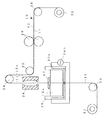
以下に、本発明をニッケル−水素蓄電池の負極に用いられる水素吸蔵合金電極に適用した場合の一実施の形態を図1に基づいて説明する。なお、図1は導電性芯体に活物質スラリーを塗着し、塗着された活物質スラリーを乾燥した後、圧延する一連の製造工程を模式的に示す断面図である。
【0011】
1.水素吸蔵合金電極の製造装置
本発明の水素吸蔵合金電極の製造装置の一例は、図1に示すように、ニッケルメッキが施された穿孔鋼板(例えば、厚みが0.06mmのパンチングメタル)からなる導電性芯材11をロール状に巻き取っている巻き出しロール21と、得られた水素吸蔵合金電極10をロール状に巻き取る巻き取りロール22と、導電性芯材11を搬送する搬送ローラー23,24,25,26と、導電性芯材11に活物質スラリー12aを塗着して塗膜を形成するスラリー槽20と、塗着された活物質スラリー12aを所定の厚みに調整するスリット27と、塗着された活物質スラリー12aを乾燥する乾燥炉28と、乾燥された電極を所定の厚みに圧延する一対の加圧ロール29とから構成される。
【0012】
なお、本実施の形態においては、予め、ニッケルメッキが施された穿孔鋼板からなる導電性芯材11をロール状に巻き取られた巻き出しロール21を所定位置に配置した後、この巻き出しロール21に巻き取られた導電性芯材11の先端部を搬送ローラー23、スラリー槽20内、スリット27、乾燥炉28、搬送ローラー24,25、加圧ロール29および搬送ローラ26を通して巻き取りロール22に巻き付けられているものとする。なお、スラリー槽20の壁内にはスラリー槽20内に収容された活物質スラリー12aを所定の温度に加温するヒータ20aが配設されているとともに、その外部にはヒータ20aに電流を供給するための電源20bが配設されている。
【0013】
2.水素吸蔵合金粉末の作製
MmNi3.4Co0.8Al0.2Mn0.6(なお、Mmはミッシュメタルである)となるように市販の各金属元素Mm,Ni,Co,Al,Mnを秤量して所定の比率で混合した。このものを高周波溶解炉に投入して溶解させた後、鋳型に流し込み、冷却してMmNi3.4Co0.8Al0.2Mn0.6からなる水素吸蔵合金の塊(インゴット)を作製した。この水素吸蔵合金の塊を粗粉砕した後、不活性ガス雰囲気中で平均粒径が50μm程度になるまで機械的に粉砕して、水素吸蔵合金粉末を作製した。なお、得られた水素吸蔵合金粉末の平均粒径はレーザ回折法により測定した値である。
【0014】
3.水素吸蔵合金電極の作製
ついで、上述のようにして作製した水素吸蔵合金粉末99質量%に、水溶性結着剤としてポリエチレンオキサイド(PEO)粉末を水素吸蔵合金粉末質量に対して1質量%と、適量の水(あるいは純水)を加えて混練して、水素吸蔵合金スラリー(活物質スラリー)12aを作製した後、この水素吸蔵合金スラリー12aをスラリー槽20内に収容した。ついで、スラリー槽20のヒータ20aに電源20bを接続した後、この電源20bからヒータ20aにヒータ電流を供給してスラリー槽20内を所定の温度に加温した。この後、巻き取りロール22を所定の速度で巻き取ることにより、巻き出しロール21にロール状に巻き取られた導電性芯材11は巻き出しロール21から巻き出されることとなる。
【0015】
これにより、スラリー槽20内の水素吸蔵合金スラリー12a中を通過する過程で導電性芯材11の両面に水素吸蔵合金スラリー12aが付着して水素吸蔵合金層12aが形成される。そして、導電性芯材11がスリット27を通過することにより余分についた水素吸蔵合金スラリー12aが掻き落とされて水素吸蔵合金層12aの塗着厚さが調整される。こうして水素吸蔵合金層12aが所定の厚さに調整された導電性芯材11は、温度が約60℃に維持された乾燥炉28内に入り、所定時間が経過することにより水素吸蔵合金層12aが乾燥される。なお、このとき乾燥炉28内に存在する時間が20分間となるように巻き取りロール22の回転速度は調整されている。
【0016】
ついで、水素吸蔵合金層12aが乾燥した導電性芯材11は一対の加圧ロール29間を通過して、水素吸蔵合金層12aが所定の厚み(0.6mm)になるように圧延して、導電性芯材11の両面に水素吸蔵合金層12を備えた水素吸蔵合金電極10を形成した後、巻き取りロール22に巻き取られる。なお、スラリー槽20内を加温して水素吸蔵合金スラリー12aの温度を30℃にして作製した水素吸蔵合金電極10を実施例1の電極Aとした。同様に、水素吸蔵合金スラリー12aの温度を35℃にして作製した水素吸蔵合金電極10を実施例2の電極Bとし、水素吸蔵合金スラリー12aの温度を40℃にして作製した水素吸蔵合金電極10を実施例3の電極Cとした。さらに、スラリー槽20内を加温しないで水素吸蔵合金スラリー12aの温度を常温(20℃)にして作製した水素吸蔵合金電極10を比較例の電極Xとした。
【0017】
4.水素吸蔵合金電極の付着強度の測定
ついで、上述のように作製した各水素吸蔵合金電極10(A,B,C,X)を所定の寸法に切断した後、片面の水素吸蔵合金層12を切削し、切削面をウエスで軽く擦って表面の切削くずを除去して試料水素吸蔵合金電極10aとした後、この試料水素吸蔵合金電極10aの付着強度を測定した。なお、この付着強度の測定においては、図2に示すように、これらの各試料水素吸蔵合金電極10aの水素吸蔵合金層12の表面に対して約30度の角度にカッター(図示せず)を保持した後、カッターの刃先に250g程度の荷重が掛かるようにして、水素吸蔵合金層12を切るように切溝x,yを引いた。なお、各切溝x,yの間隔は1mm間隔とし、各切溝x,yをそれぞれ10本ずつ互いに直角に交差するように引いた。
【0018】
ついで、各切溝x,yを10本ずつ互いに直角に交差するように引くことにより、碁盤目状に100個の升目を形成した。ついで、碁盤目状に100個の升目が形成された各試料水素吸蔵合金電極10aをそれぞれ10枚ずつ用いて、試料水素吸蔵合金電極10aが垂直になるようにして、高さが約100mmの位置まで持ち上げた後、各試料水素吸蔵合金電極10aをそれぞれ自由落下させた。この落下試験を3回繰り返して行った後、各試料水素吸蔵合金電極10aに形成された升目の脱落個数を数えて、その平均値を求めると下記の表1に示すような結果となった。
【0019】
【表1】

上記表1の結果から明らかなように、水素吸蔵合金スラリー12aの温度を20℃(常温)にして作製した試料水素吸蔵合金電極Xの平均脱落数が30個であるのに対して、水素吸蔵合金スラリー12aの温度を30℃にして作製した試料水素吸蔵合金電極Aの平均脱落数は10個で、水素吸蔵合金スラリー12aの温度を35℃にして作製した試料水素吸蔵合金電極Bの平均脱落数は8個で、水素吸蔵合金スラリー12aの温度を40℃にして作製した試料水素吸蔵合金電極Cの平均脱落数は7個で、試料水素吸蔵合金電極Xよりも水素吸蔵合金スラリー12aの温度を高くするに従って平均脱落数が極めて低下することが分かる。
【0021】
これは、加温された水素吸蔵合金スラリー12aを導電性芯体11に塗着するようにすると、塗着された水素吸蔵合金スラリー12aを乾燥炉28内に投入しても、乾燥炉28内の雰囲気温度(約60℃)と水素吸蔵合金スラリー12aの温度(30〜40℃)との間の温度勾配が小さくなるため、水素吸蔵合金スラリー12a中の結着剤が水素吸蔵合金電極10の表面に移動することが抑制されるようになる。このため、導電性芯体11の近傍の活物質層中の結着剤量が減少することが防止できるようになって、導電性芯体11の近傍の水素吸蔵合金粉末同士の結着力あるいは導電性芯体11と水素吸蔵合金粉末との結着力を維持できるようになったと考えられる。この結果、水素吸蔵合金電極10の付着強度が向上して、活物質層12が導電性芯体11より脱落することを防止することが可能となる。
【0022】
この場合、加温された水素吸蔵合金スラリー12aの温度が30℃未満であると、乾燥炉28内の雰囲気温度と水素吸蔵合金スラリー12aの温度との間の温度勾配が大きくなる。このため、水素吸蔵合金スラリー12aの乾燥時に、水素吸蔵合金スラリー12a中の結着剤が水素吸蔵合金電極10の表面に移動するようになって、導電性芯体11の近傍の水素吸蔵合金層12a中の結着剤量が減少し、導電性芯体11の近傍の水素吸蔵合金粉末同士の結着力あるいは導電性芯体11と水素吸蔵合金粉末との結着力が低下することとなる。
このため、水素吸蔵合金スラリー12aを加温する温度は30℃以上に規定する必要がある。この場合、水素吸蔵合金スラリー12aを結着剤が分解される温度以上に加温すると結着剤の機能を発揮することができなくなるので、水素吸蔵合金スラリー12aを加温する温度の上限値は結着剤が分解されないような温度にする必要がある。
【0023】
上述したように、本発明においては、加温された水素吸蔵合金スラリー12aを導電性芯体11に塗着するようにしているので、乾燥炉28内で高温で急速に乾燥させても、乾燥炉28内の雰囲気温度と水素吸蔵合金スラリー12aの温度との間の温度勾配が小さくなる。このため、高温で急速乾燥させて水素吸蔵合金電極の生産性を向上させても、導電性芯体11の近傍の活物質層中の結着剤量が減少することが防止できる。これにより、導電性芯体11の近傍の水素吸蔵合金粉末同士の結着力あるいは導電性芯体11と水素吸蔵合金粉末との結着力を維持できるようになって、水素吸蔵合金電極10の付着強度が向上し、活物質層12が導電性芯体11より脱落することを防止することが可能となる。
【0024】
なお、上述した実施の形態においては、スラリー槽20にヒータ20aを設け、このヒータ20aに電源20bを接続してヒータ電流を供給し、スラリー槽20内に収容された水素吸蔵合金スラリー12aを所定の温度に加温する例について説明したが、水素吸蔵合金スラリー12aを所定の温度に加温する手段としては、これに限らず、種々の熱源を用いてスラリー槽20を加熱するようにしてもよいし、水素吸蔵合金スラリー12aをスラリー槽20の外で加熱してからスラリー槽20に注入するようにしてもよい。
【0025】
また、上述した実施の形態においては、乾燥炉28内の雰囲気温度(加熱温度)を約60℃に維持して水素吸蔵合金層12を乾燥させるようにした例について説明したが、乾燥炉28内の雰囲気温度(加熱温度)は50〜100℃の範囲内であれば何度でもよく、活物質スラリーを構成する活物質、結着剤、得られる電極の厚み等を考慮して適宜選択するようにすればよい。なお、活物質が塗着された電極の乾燥温度を変化させる場合は、活物質スラリーとの温度勾配が大きくならないように、活物質スラリーの温度もこれに対応して変化させる必要がある。
【0026】
また、上述した実施の形態においては、MmNi3.4Co0.8Al0.2Mn0.6で表される水素吸蔵合金を用いる例について説明したが、MmaNibCocMndAleで表される水素吸蔵合金、LaNi5系でNiの一部をCoとAl,W等で置換したAB5型希土類系の水素吸蔵合金等を用いるようにしてもよい。また、上述した実施の形態においては、機械的に粉砕した水素吸蔵合金を用いる例について説明したが、アトマイズ法により作製した水素吸蔵合金あるいはこれに粉砕合金を混合した混合粉末を用いるようにしてもよい。
【0027】
また、上述した実施の形態においては、本発明の製造方法を水素吸蔵合金電極に適用する例について説明したが、本発明は水素吸蔵合金電極に限らず、カドミウム電極、ニッケル電極などの導電性芯体に直接活物質スラリーを塗着して形成する種々のアルカリ蓄電池用電極に適用することができる。
さらに、上述した実施の形態においては、結着剤としてポリエチレンオキサイド(PEO)を用いる例について説明したが、結着剤としてはPEOに限らず、PTFE、SBR等の各種の結着剤を用いることができる。この場合、用いる結着剤に応じて溶媒を選択する必要がある。
【図面の簡単な説明】
【図1】 導電性芯体に活物質スラリーを塗着し、塗着された活物質スラリーを乾燥した後、圧延する一連の製造工程を模式的に示す断面図である。
【図2】 活物質の脱落試験を行うために活物質層に碁盤目状の切溝を入れた状態を模式的に示す斜視図である。
【符号の説明】
10…水素吸蔵合金極板、11…導電性芯体(パンチングメタル)、12…水素吸蔵合金層(活物質層)、12a…水素吸蔵合金スラリー(活物質スラリー)、20…スラリー槽、20a…ヒータ、20b…電源、21…巻き出しロール、22…巻き取りロール、23,24,25,26…搬送ローラー、27…スリット、28…乾燥炉、29…加圧ロール[0001]
BACKGROUND OF THE INVENTION
The present invention relates to a method for producing an electrode for an alkaline storage battery, wherein an active material slurry comprising an active material powder, a binder, and a solvent for the binder is applied to a conductive core.
[0002]
[Prior art]
In recent years, with the increase in the number of small portable devices, the demand for secondary batteries (storage batteries) that can be charged and discharged has increased. In particular, with the downsizing, thinning, and space efficiency of devices, large capacity has been obtained and The demand for alkaline storage batteries such as inexpensive nickel-hydrogen storage batteries has increased rapidly. An electrode used in this type of alkaline storage battery becomes an active material powder, a water-soluble binder, and a solvent for the water-soluble binder on both surfaces of a conductive core made of a punching metal or the like that holds an active material layer. It is formed by applying pure water or an active material slurry formed by kneading water, but it is usually natural at room temperature (about 20 ° C.) after applying the active material slurry on both sides of the conductive core. It is produced through a drying process.
[0003]
Here, when the alkaline storage battery electrode coated with the active material slurry is naturally dried, the drying speed is slow, and usually a long drying time of about 5 to 6 hours is required until the alkaline storage battery electrode is dried. Therefore, there has been a problem that the production efficiency of the electrode for an alkaline storage battery is poor.
Therefore, in order to solve such problems, a method has been proposed in which an active material slurry is applied to both surfaces of a conductive core and then dried at a high temperature (about 60 ° C.). Thus, when the alkaline storage battery electrode coated with the active material slurry is dried at a high temperature, the drying time can be dried in about 15 to 30 minutes, and the production efficiency of the alkaline storage battery electrode is improved. It will be.
[0004]
[Problems to be solved by the invention]
By the way, in order to increase the drying speed of the alkaline storage battery electrode and improve the production efficiency, it is necessary to dry the alkaline storage battery electrode at a high temperature as described above, but when the alkaline storage battery electrode is dried at a high temperature, Since the evaporation rate of moisture is increased, the moisture contained in the active material layer rapidly moves from the inside of the alkaline storage battery electrode to the surface (dry surface side). However, when the moisture contained in the active material layer moves rapidly, the binder contained in the active material layer also moves as the moisture moves. As a result, since the transferred binder is unevenly distributed and solidified on the surface of the alkaline storage battery electrode, the amount of the binder in the active material layer in the vicinity of the conductive core disposed in the center of the alkaline storage battery electrode Caused the phenomenon of decrease.
[0005]
Here, when the amount of the binder in the active material layer near the conductive core decreases, the adhesive force between the active materials existing near the conductive core or the adhesive force between the conductive core and the active material decreases. For this reason, the problem arises that the active material layer is more easily removed from the conductive core.
Therefore, the present invention has been made to solve the above problems, and even if the drying temperature of the alkaline storage battery electrode coated with the active material is increased to improve production efficiency, the alkaline storage battery electrode can be improved. It is an object of the present invention to provide a production method capable of suppressing a decrease in the strength of the active material layer, to prevent the active material layer from falling off the conductive core, and to obtain a high-quality alkaline storage battery.
[0006]
[Means for Solving the Problems]
In order to achieve the above object, the present invention provides a method for producing an alkaline storage battery electrode, wherein an active material slurry comprising an active material powder, a binder, and a solvent for the binder is applied to a conductive core. An active material powder, a binder, and a solvent for the binder to produce an active material slurry; a slurry heating step for heating the active material slurry; A slurry coating step of coating the slurry on the conductive core, a drying step of heating and drying the electrode coated on the conductive core in the slurry coating step, and rolling the dried electrode And a heating temperature of the slurry in the slurry heating process is 30 ° C. or higher and lower than the heating temperature of the electrode in the drying process, and the atmosphere temperature and the temperature of the slurry in the drying process this is warmed so that the temperature gradient is small between the The features.
[0007]
As described above, after the active material slurry is heated, the heated active material slurry is applied to the conductive core, and then the active material slurry is heated and dried in a drying furnace. Even if it is added, the temperature gradient between the atmospheric temperature in the drying furnace and the temperature of the active material slurry is reduced. For this reason, since the binder in the active material slurry is restrained from moving as described above, it is possible to prevent the amount of the binder in the active material layer near the conductive core from decreasing. become. As a result, the adhesive strength between the active material powders in the vicinity of the conductive core or the adhesive strength between the conductive core and the active material powder can be maintained, and the adhesive strength of this type of alkaline storage battery electrode is improved. Thus, the active material layer can be prevented from falling off the conductive core.
[0008]
And in order to demonstrate the effect of heating the active material slurry as in the present invention, a drying step of heating and drying the electrode coated with the heated active material slurry on the conductive core, It is particularly effective when applied to a method for producing an alkaline storage battery electrode comprising a pressing step for rolling a dried electrode. Note that the heating temperature of the slurry in the active material slurry heating step needs to be lower than the drying temperature.
[0009]
In this case, if the temperature of the heated active material slurry is less than 30 ° C., the temperature gradient between the atmosphere temperature in the drying furnace and the temperature of the active material slurry in the subsequent drying step does not become small, so that drying is performed. The binder in the active material slurry moves to the electrode surface in the furnace, and the amount of the binder in the active material layer near the conductive core is reduced, so that the conductive core and the active material powder are reduced. The adhesive strength with will be reduced. For this reason, it is necessary to prescribe | regulate the heating temperature of the slurry in an active material slurry heating process to 30 degreeC or more. And if the temperature is higher than the temperature at which the binder is decomposed, the function of the binder cannot be exhibited, so the upper limit of the temperature at which the active material slurry is heated is a temperature at which the binder is not decomposed. It is necessary to.
[0010]
DETAILED DESCRIPTION OF THE INVENTION
An embodiment in which the present invention is applied to a hydrogen storage alloy electrode used for a negative electrode of a nickel-hydrogen storage battery will be described below with reference to FIG. FIG. 1 is a cross-sectional view schematically showing a series of manufacturing steps in which an active material slurry is applied to a conductive core, and the applied active material slurry is dried and then rolled.
[0011]
1. 1. Hydrogen Storage Alloy Electrode Manufacturing Apparatus An example of the hydrogen storage alloy electrode manufacturing apparatus of the present invention is made of a perforated steel sheet (for example, a punching metal having a thickness of 0.06 mm) plated with nickel as shown in FIG. An unwinding roll 21 that winds the conductive core material 11 in a roll shape, a winding roll 22 that winds the obtained hydrogen
[0012]
In the present embodiment, a winding roll 21 in which a conductive core 11 made of a nickel-plated perforated steel sheet is wound in a roll shape is disposed in a predetermined position, and then the winding roll. A winding roll 22 is passed through the leading end portion of the conductive core 11 wound around 21 through the conveying
[0013]
2. Preparation of hydrogen storage alloy powder MmNi 3.4 Co 0.8 Al 0.2 Mn 0.6 (Mm is Misch metal) Each of the commercially available metal elements Mm, Ni, Co, Al, Mn is weighed at a predetermined ratio. Mixed. This was put into a high frequency melting furnace and melted, then poured into a mold and cooled to prepare a hydrogen storage alloy lump (ingot) composed of MmNi 3.4 Co 0.8 Al 0.2 Mn 0.6 . This lump of hydrogen storage alloy was coarsely pulverized and then mechanically pulverized in an inert gas atmosphere until the average particle size became about 50 μm to prepare a hydrogen storage alloy powder. In addition, the average particle diameter of the obtained hydrogen storage alloy powder is a value measured by a laser diffraction method.
[0014]
3. Production of hydrogen storage alloy electrode Next, 99 mass% of the hydrogen storage alloy powder produced as described above, polyethylene oxide (PEO) powder as a water-soluble binder, 1 mass% with respect to the mass of the hydrogen storage alloy powder, An appropriate amount of water (or pure water) was added and kneaded to prepare a hydrogen storage alloy slurry (active material slurry) 12a, and then the hydrogen storage alloy slurry 12a was accommodated in the
[0015]
Thereby, in the process of passing through the hydrogen storage alloy slurry 12a in the
[0016]
Next, the conductive core material 11 from which the hydrogen storage alloy layer 12a has been dried passes between the pair of pressure rolls 29 and is rolled so that the hydrogen storage alloy layer 12a has a predetermined thickness (0.6 mm). After forming the hydrogen
[0017]
4). Measurement of adhesion strength of hydrogen storage alloy electrode Next, each of the hydrogen storage alloy electrodes 10 (A, B, C, X) produced as described above was cut to a predetermined size, and then the hydrogen storage alloy layer 12 on one side was cut. Then, the cutting surface was lightly rubbed with a waste cloth to remove cutting chips on the surface to obtain a sample hydrogen storage alloy electrode 10a, and then the adhesion strength of the sample hydrogen storage alloy electrode 10a was measured. In the measurement of the adhesion strength, as shown in FIG. 2, a cutter (not shown) is used at an angle of about 30 degrees with respect to the surface of the hydrogen storage alloy layer 12 of each sample hydrogen storage alloy electrode 10a. After being held, kerfs x and y were drawn so as to cut the hydrogen storage alloy layer 12 so that a load of about 250 g was applied to the blade edge of the cutter. The intervals between the kerfs x and y were 1 mm, and ten kerfs x and y were drawn so as to intersect each other at right angles.
[0018]
Subsequently, 100 grids were formed in a grid pattern by pulling 10 each of the kerfs x and y so as to cross each other at right angles. Next, 10 pieces of each of the sample hydrogen storage alloy electrodes 10a each having 100 grids formed in a grid pattern are used so that the sample hydrogen storage alloy electrodes 10a are vertical and the height is about 100 mm. Each sample hydrogen storage alloy electrode 10a was dropped freely. After this drop test was repeated three times, the number of grids formed on each sample hydrogen storage alloy electrode 10a was counted, and the average value was obtained as shown in Table 1 below.
[0019]
[Table 1]
As is clear from the results in Table 1 above, the average occlusion number of the sample hydrogen storage alloy electrode X produced by setting the temperature of the hydrogen storage alloy slurry 12a to 20 ° C. (normal temperature) is 30, whereas hydrogen storage The average number of dropouts of the sample hydrogen storage alloy electrode A prepared at 30 ° C. of the alloy slurry 12a is 10, and the average dropout of the sample hydrogen storage alloy electrode B prepared at 35 ° C of the hydrogen storage alloy slurry 12a. The number of the sample hydrogen storage alloy electrodes C produced by setting the temperature of the hydrogen storage alloy slurry 12a to 40 ° C. was 7, and the average number of drops of the sample hydrogen storage alloy electrode C was 7, and the temperature of the hydrogen storage alloy slurry 12a was higher than that of the sample hydrogen storage alloy electrode X. It can be seen that the average dropout number decreases significantly as the value is increased.
[0021]
This is because if the heated hydrogen storage alloy slurry 12a is applied to the conductive core 11, even if the applied hydrogen storage alloy slurry 12a is put into the drying
[0022]
In this case, if the temperature of the heated hydrogen storage alloy slurry 12a is less than 30 ° C., the temperature gradient between the atmospheric temperature in the drying
For this reason, the temperature at which the hydrogen storage alloy slurry 12a is heated needs to be regulated to 30 ° C. or higher. In this case, if the hydrogen storage alloy slurry 12a is heated to a temperature higher than the temperature at which the binder is decomposed, the function of the binder cannot be exhibited. Therefore, the upper limit of the temperature at which the hydrogen storage alloy slurry 12a is heated is The temperature must be such that the binder is not decomposed.
[0023]
As described above, in the present invention, since the heated hydrogen storage alloy slurry 12a is applied to the conductive core 11, even if it is rapidly dried at a high temperature in the drying
[0024]
In the above-described embodiment, the heater 20a is provided in the
[0025]
In the embodiment described above, the example in which the atmosphere temperature (heating temperature) in the drying
[0026]
Further, in the above embodiment, description has been made of an example of using a hydrogen storage alloy represented by MmNi 3.4 Co 0.8 Al 0.2 Mn 0.6 , the hydrogen storage alloy represented by Mm a Ni b Co c Mn d Al e , a part of Ni may be used Co and Al, the hydrogen storage alloy of AB 5 type rare earth substituted with W or the like or the like in LaNi 5 type. In the above-described embodiments, examples of using a mechanically pulverized hydrogen storage alloy have been described. However, a hydrogen storage alloy prepared by an atomizing method or a mixed powder in which a pulverized alloy is mixed with the hydrogen storage alloy may be used. Good.
[0027]
In the above-described embodiment, the example in which the production method of the present invention is applied to a hydrogen storage alloy electrode has been described. However, the present invention is not limited to a hydrogen storage alloy electrode, but a conductive core such as a cadmium electrode or a nickel electrode. The present invention can be applied to various alkaline storage battery electrodes formed by directly applying an active material slurry to the body.
Furthermore, in the above-described embodiment, an example in which polyethylene oxide (PEO) is used as the binder has been described. However, the binder is not limited to PEO, and various binders such as PTFE and SBR are used. Can do. In this case, it is necessary to select a solvent according to the binder used.
[Brief description of the drawings]
FIG. 1 is a cross-sectional view schematically showing a series of manufacturing steps in which an active material slurry is applied to a conductive core, and the applied active material slurry is dried and then rolled.
FIG. 2 is a perspective view schematically showing a state in which a grid-like cut groove is formed in an active material layer in order to perform an active material drop-out test.
[Explanation of symbols]
DESCRIPTION OF
Claims (1)
前記活物質粉末と結着剤と該結着剤の溶媒とを混合して活物質スラリーを作製する活物質スラリー作製工程と、
前記活物質スラリーを加温するスラリー加温工程と、
前記加温されたスラリーを導電性芯体に塗着するスラリー塗着工程と、
前記スラリー塗着工程にて前記導電性芯体に塗着された電極を加熱して乾燥する乾燥工程と、
前記乾燥された電極を圧延する加圧工程とを備え、
前記スラリー加温工程でのスラリーの加温温度は30℃以上で前記乾燥工程での電極の加熱温度よりも低温であるとともに、前記乾燥工程での雰囲気温度と前記スラリーの温度との間の温度勾配が小さくなるように加温されることを特徴とするアルカリ蓄電池用電極の製造方法。A method for producing an electrode for an alkaline storage battery, wherein an active material slurry comprising an active material powder, a binder, and a solvent for the binder is applied to a conductive core,
An active material slurry preparation step of preparing an active material slurry by mixing the active material powder, a binder, and a solvent of the binder;
A slurry heating step for heating the active material slurry;
And slurry the coating step of Nurigi the heated slurry to the conductive core,
A drying step of heating and drying the electrode coated on the conductive core in the slurry coating step;
A pressing step for rolling the dried electrode,
The temperature of the slurry in the slurry heating step is 30 ° C. or higher and lower than the heating temperature of the electrode in the drying step, and a temperature between the ambient temperature in the drying step and the temperature of the slurry A method for producing an electrode for an alkaline storage battery, wherein the heating is performed so that the gradient becomes small .
Priority Applications (5)
| Application Number | Priority Date | Filing Date | Title |
|---|---|---|---|
| JP2001053583A JP4390397B2 (en) | 2001-02-28 | 2001-02-28 | Method for producing alkaline storage battery electrode |
| EP02004520A EP1237211A3 (en) | 2001-02-28 | 2002-02-27 | Method for producing electrode for alkali batteries |
| CNB021067112A CN1200471C (en) | 2001-02-28 | 2002-02-28 | Method for mfg. electrode of alkaline cell |
| US10/084,161 US6641869B2 (en) | 2001-02-28 | 2002-02-28 | Method for producing electrode for alkali batteries |
| HK03101997.8A HK1049916B (en) | 2001-02-28 | 2003-03-18 | Method for producing electrode for alkali batteries |
Applications Claiming Priority (1)
| Application Number | Priority Date | Filing Date | Title |
|---|---|---|---|
| JP2001053583A JP4390397B2 (en) | 2001-02-28 | 2001-02-28 | Method for producing alkaline storage battery electrode |
Publications (2)
| Publication Number | Publication Date |
|---|---|
| JP2002260646A JP2002260646A (en) | 2002-09-13 |
| JP4390397B2 true JP4390397B2 (en) | 2009-12-24 |
Family
ID=18914028
Family Applications (1)
| Application Number | Title | Priority Date | Filing Date |
|---|---|---|---|
| JP2001053583A Expired - Fee Related JP4390397B2 (en) | 2001-02-28 | 2001-02-28 | Method for producing alkaline storage battery electrode |
Country Status (5)
| Country | Link |
|---|---|
| US (1) | US6641869B2 (en) |
| EP (1) | EP1237211A3 (en) |
| JP (1) | JP4390397B2 (en) |
| CN (1) | CN1200471C (en) |
| HK (1) | HK1049916B (en) |
Families Citing this family (10)
| Publication number | Priority date | Publication date | Assignee | Title |
|---|---|---|---|---|
| US7404842B1 (en) * | 2003-01-23 | 2008-07-29 | Jesse Wainright | Microfabricated hydrogen storage device and metal hydride fuel cell/battery |
| CN100389514C (en) * | 2004-08-03 | 2008-05-21 | 比亚迪股份有限公司 | Preparation method for nickel positive electrode sheet of alkaline storage battery |
| JP5160891B2 (en) | 2005-05-09 | 2013-03-13 | パナソニック株式会社 | Method and apparatus for applying electrode mixture paste |
| JP4581888B2 (en) * | 2005-07-25 | 2010-11-17 | Tdk株式会社 | Electrode element manufacturing method and electrochemical element manufacturing method |
| JP5082406B2 (en) * | 2006-11-28 | 2012-11-28 | パナソニック株式会社 | Method for producing negative electrode of nonaqueous electrolyte secondary battery |
| CN101552335B (en) * | 2009-04-30 | 2010-10-13 | 深圳市豪鹏科技有限公司 | Method for manufacturing battery negative pole piece |
| US10119932B2 (en) * | 2014-05-28 | 2018-11-06 | Honeywell International Inc. | Electrochemical gas sensor |
| CN106410206A (en) * | 2016-06-23 | 2017-02-15 | 盈天科技(深圳)有限公司 | Coating layer for improving conductivity of lithium ion battery electrode |
| CN112038567A (en) * | 2020-08-12 | 2020-12-04 | 北京化工大学 | Continuous production device and production process of electrode |
| CN112652824A (en) * | 2021-01-21 | 2021-04-13 | 天津市捷威动力工业有限公司 | Cylindrical lithium ion battery manufacturing process |
Family Cites Families (7)
| Publication number | Priority date | Publication date | Assignee | Title |
|---|---|---|---|---|
| US5096611A (en) * | 1989-05-25 | 1992-03-17 | Globe-Union Inc. | Process for the production of battery paste |
| JP3030149B2 (en) * | 1992-01-17 | 2000-04-10 | 三洋電機株式会社 | Non-aqueous electrolyte battery |
| JP2639620B2 (en) * | 1993-10-13 | 1997-08-13 | 古河電池株式会社 | Manufacturing method of hydrogen storage alloy electrode |
| WO1995029509A1 (en) * | 1994-04-20 | 1995-11-02 | Valence Technology, Inc. | Method for producing low porosity electrode |
| JPH09231977A (en) * | 1996-02-27 | 1997-09-05 | Elf Atochem Japan Kk | Electrode and its manufacture |
| JP3995791B2 (en) * | 1998-03-26 | 2007-10-24 | Tdk株式会社 | Method for producing electrode for non-aqueous electrolyte battery |
| ATE381767T1 (en) * | 1999-02-05 | 2008-01-15 | Kureha Corp | COMPOSITION FOR PRODUCING ELECTRODES, ACTIVE CARBON ELECTRODE AND ELECTRICAL DOUBLE LAYER CAPACITOR |
-
2001
- 2001-02-28 JP JP2001053583A patent/JP4390397B2/en not_active Expired - Fee Related
-
2002
- 2002-02-27 EP EP02004520A patent/EP1237211A3/en not_active Withdrawn
- 2002-02-28 CN CNB021067112A patent/CN1200471C/en not_active Expired - Fee Related
- 2002-02-28 US US10/084,161 patent/US6641869B2/en not_active Expired - Fee Related
-
2003
- 2003-03-18 HK HK03101997.8A patent/HK1049916B/en not_active IP Right Cessation
Also Published As
| Publication number | Publication date |
|---|---|
| CN1373527A (en) | 2002-10-09 |
| EP1237211A3 (en) | 2005-11-02 |
| JP2002260646A (en) | 2002-09-13 |
| CN1200471C (en) | 2005-05-04 |
| HK1049916A1 (en) | 2003-05-30 |
| US6641869B2 (en) | 2003-11-04 |
| HK1049916B (en) | 2005-08-12 |
| EP1237211A2 (en) | 2002-09-04 |
| US20020160101A1 (en) | 2002-10-31 |
Similar Documents
| Publication | Publication Date | Title |
|---|---|---|
| JP3016769B1 (en) | Method of manufacturing electrode plate for battery, electrode plate manufactured by the method, and battery provided with the electrode plate | |
| JP4390397B2 (en) | Method for producing alkaline storage battery electrode | |
| EP0867248B1 (en) | Method of manufacturing porous metal sheet | |
| CN110649265A (en) | Conductive agent material, battery pole piece and application | |
| JPS59134563A (en) | Production process of collector for electrode | |
| TW518783B (en) | Hydrogen absorbing alloy electrode, manufacturing method thereof, and alkaline storage battery equipped with the hydrogen absorbing alloy electrode | |
| JP5294809B2 (en) | Method for producing sintered nickel substrate | |
| JP4056207B2 (en) | Method for producing alkaline storage battery | |
| JP2006505917A (en) | Electrode, electrode manufacturing method, and bipolar battery | |
| JP3454606B2 (en) | Method for producing positive electrode active material for alkaline storage battery | |
| CA2232697A1 (en) | Method of manufacturing metal sheet and metal sheet manufactured by manufacturing method | |
| JP3761763B2 (en) | Hydrogen storage alloy electrode, battery using the same, and manufacturing method thereof | |
| JPH10237569A (en) | Hydrogen storate alloy for battery, its production and nickel-hydrogen secondary battery | |
| CA2103490A1 (en) | Metal hydride electrode, cell and process | |
| JPH10265875A (en) | Hydrogen storage alloy, its production and nickel-hydrogen secondary battery | |
| JP4461509B2 (en) | Method and apparatus for producing alloy powder sheet used as negative electrode of nickel metal hydride secondary battery | |
| JPH10172550A (en) | Alkaline battery with nickel positive electrode and its activating method | |
| KR20230158828A (en) | Method for preparing dry electrode sheet for secondary battery, dry electrode sheet for secondary battery and secondary battery comprising the same | |
| JP2001011507A (en) | Method and equipment for manufacturing alloy powder sheet | |
| JP2002231236A (en) | Hydrogen storage alloy electrode, method of manufacturing the same, and alkaline battery with hydrogen storage alloy electrode | |
| JPH09147851A (en) | Manufacture of hydrogen storage alloy electrode | |
| JPH09289017A (en) | Hydrogen storage alloy for battery and nickel hydrogen secondary battery | |
| JP2000133254A (en) | Nickel-hydrogen battery and manufacture of same | |
| JPH10102174A (en) | Hydrogen storage alloy, its production, and nickel-hydrogen secondary battery | |
| JP2002063897A (en) | Manufacturing method of alkaline battery |
Legal Events
| Date | Code | Title | Description |
|---|---|---|---|
| A621 | Written request for application examination |
Free format text: JAPANESE INTERMEDIATE CODE: A621 Effective date: 20050214 |
|
| A977 | Report on retrieval |
Free format text: JAPANESE INTERMEDIATE CODE: A971007 Effective date: 20080226 |
|
| A131 | Notification of reasons for refusal |
Free format text: JAPANESE INTERMEDIATE CODE: A131 Effective date: 20080318 |
|
| A521 | Request for written amendment filed |
Free format text: JAPANESE INTERMEDIATE CODE: A523 Effective date: 20080515 |
|
| TRDD | Decision of grant or rejection written | ||
| A01 | Written decision to grant a patent or to grant a registration (utility model) |
Free format text: JAPANESE INTERMEDIATE CODE: A01 Effective date: 20090908 |
|
| A01 | Written decision to grant a patent or to grant a registration (utility model) |
Free format text: JAPANESE INTERMEDIATE CODE: A01 |
|
| A61 | First payment of annual fees (during grant procedure) |
Free format text: JAPANESE INTERMEDIATE CODE: A61 Effective date: 20091006 |
|
| FPAY | Renewal fee payment (event date is renewal date of database) |
Free format text: PAYMENT UNTIL: 20121016 Year of fee payment: 3 |
|
| FPAY | Renewal fee payment (event date is renewal date of database) |
Free format text: PAYMENT UNTIL: 20121016 Year of fee payment: 3 |
|
| FPAY | Renewal fee payment (event date is renewal date of database) |
Free format text: PAYMENT UNTIL: 20121016 Year of fee payment: 3 |
|
| FPAY | Renewal fee payment (event date is renewal date of database) |
Free format text: PAYMENT UNTIL: 20131016 Year of fee payment: 4 |
|
| LAPS | Cancellation because of no payment of annual fees |