JP4381652B2 - Game machine - Google Patents
Game machine Download PDFInfo
- Publication number
- JP4381652B2 JP4381652B2 JP2002140828A JP2002140828A JP4381652B2 JP 4381652 B2 JP4381652 B2 JP 4381652B2 JP 2002140828 A JP2002140828 A JP 2002140828A JP 2002140828 A JP2002140828 A JP 2002140828A JP 4381652 B2 JP4381652 B2 JP 4381652B2
- Authority
- JP
- Japan
- Prior art keywords
- variable display
- game
- selection
- effect control
- option
- Prior art date
- Legal status (The legal status is an assumption and is not a legal conclusion. Google has not performed a legal analysis and makes no representation as to the accuracy of the status listed.)
- Expired - Fee Related
Links
Images


Description
【0001】
【発明の属する技術分野】
本発明は、表示状態が変化可能な可変表示手段を有し、可変表示手段における表示結果が特定表示態様となったときに遊技者にとって有利な特定遊技状態に制御可能となるパチンコ機等の遊技機に関する。
【0002】
【従来の技術】
遊技機として、遊技球などの遊技媒体を発射装置によって遊技領域に発射し、遊技領域に設けられている入賞口などの入賞領域に遊技媒体が入賞すると、所定個の賞球が遊技者に払い出されるものがある。さらに、識別情報を可変表示可能な可変表示手段が設けられ、当該識別情報の可変表示の表示結果が特定の表示結果となった場合に遊技者にとって有利な特定遊技状態に制御可能となるように構成されたものがある。
【0003】
特定遊技状態とは、所定の遊技価値が付与された遊技者にとって有利な状態を意味する。具体的には、特定遊技状態は、例えば、例えば可変入賞球装置の状態が打球が入賞しやすい遊技者にとって有利な状態(大当り遊技状態)、遊技者にとって有利な状態となるための権利が発生した状態、景品遊技媒体払出の条件が成立しやすくなる状態などの、所定の遊技価値が付与された状態である。
【0004】
パチンコ遊技機では、特別図柄(識別情報)を表示する可変表示手段の表示結果があらかじめ定められた特定の表示態様の組合せとなることを、通常、「大当り」という。大当りが発生すると、例えば、大入賞口が所定回数開放して打球が入賞しやすい大当り遊技状態に移行する。そして、各開放期間において、所定個(例えば10個)の大入賞口への入賞があると大入賞口は閉成する。そして、大入賞口の開放回数は、所定回数(例えば15ラウンド)に固定されている。なお、各開放について開放時間(例えば29.5秒)が決められ、入賞数が所定個に達しなくても開放時間が経過すると大入賞口は閉成する。また、大入賞口が閉成した時点で所定の条件(例えば、大入賞口内に設けられているVゾーンへの入賞)が成立していない場合には、大当り遊技状態は終了する。
【0005】
また、可変表示手段において最終停止図柄(例えば左右中図柄のうち中図柄)となる図柄以外の図柄が、所定時間継続して、特定の表示結果と一致している状態で停止、揺動、拡大縮小もしくは変形している状態、または、複数の図柄が同一図柄で同期して変動したり、表示図柄の位置が入れ替わっていたりして、最終結果が表示される前で大当り発生の可能性が継続している状態(以下、これらの状態をリーチ状態という。)において行われる演出をリーチ演出という。また、リーチ状態やその様子をリーチ態様という。さらに、リーチ演出を含む可変表示をリーチ可変表示という。リーチ状態において、変動パターンを通常状態における変動パターンとは異なるパターンにすることによって、遊技の興趣が高められている。そして、可変表示手段に可変表示される図柄の表示結果がリーチ状態となる条件を満たさない場合には「はずれ」となり、可変表示状態は終了する。遊技者は、大当りをいかにして発生させるかを楽しみつつ遊技を行う。
【0006】
遊技機には、遊技の全体的な進行を制御する遊技制御手段が搭載された遊技制御基板の他に種々の制御手段が搭載された制御基板が設けられている。そして、遊技制御手段は、電気部品に対する制御指示を示す制御コマンドを、遊技状況に応じて、各制御基板に搭載された各制御手段に送信する。各制御手段として、例えば、電気部品としての可変表示装置の制御を行う表示制御手段、電気部品としての演出制御用の発光体(ランプやLED)の制御を行うランプ制御手段、電気部品としてのスピーカからの音発生の制御を行う音制御手段がある。
【0007】
【発明が解決しようとする課題】
遊技制御手段が多数の制御手段に対して制御コマンドを送信するように構成すると、遊技制御手段の負担が過大になる。そこで、遊技制御手段から制御コマンドを受けた各制御手段が独自に演出内容を決定して演出を実行するように構成されることがある。しかし、そのような構成では、各制御手段は、他の制御手段との間で演出の同期をとらなければならず、各制御手段の負担が過大になる。
【0009】
そこで、本発明は、遊技制御手段およびその他の制御手段の負担を増すことなく、演出内容をより豊富にして遊技の興趣をより増進させることができる遊技機を提供することを目的とする。
【0010】
【課題を解決するための手段】
本発明による遊技機は、複数種類の識別情報を可変表示可能な可変表示部(例えば可変表示装置9)を備え、可変表示部における識別情報の表示結果が特定の表示結果(例えば左中右図柄が揃った大当り図柄)となったときに遊技者にとって有利な特定遊技状態(例えば大当り遊技状態)に制御可能となる遊技機であって、遊技の進行を制御する遊技制御手段(例えばCPU56等)と、遊技制御手段からのコマンド(例えば演出制御コマンド)にもとづいて識別情報の可変表示に関わる演出を実行する複数種類の演出手段(例えば可変表示装置9、ランプ・LED、スピーカ27、演出用の可動部材)を制御する演出制御手段(例えば演出制御用CPU101等)と、遊技者の選択操作を入力するための選択手段(例えば発光部17a,17bと受光部19a,19bとによる人体センサ)とを備え、遊技制御手段は、特定遊技状態に制御するか否かを、識別情報の表示結果が導出表示される前に決定する事前決定手段(例えば遊技制御手段におけるステップS55〜S58の処理を実行する部分)と、事前決定手段による決定結果にもとづいて、特定の可変表示パターンを含む複数種類の可変表示パターンの中から、識別情報の可変表示に用いる可変表示パターンを決定する可変表示パターン決定手段と、可変表示パターン決定手段によって決定された可変表示パターンを特定可能な可変表示パターンコマンドを送信するコマンド送信手段とを含み、所定の処理を繰り返し実行するメインルーチンと、メインルーチン実行中の所定時間毎に発生するタイマ割込に応じてメインルーチンを中断して起動される割込ルーチンとを実行し、割込ルーチンにおいて、事前決定手段が特定遊技状態とするか否か決定するための特定遊技状態決定用数値を所定の数値範囲内で更新する特定遊技状態決定用数値更新処理を実行し、メインルーチンにおいて、特定遊技状態決定用数値の初期値となる特定遊技初期値用数値を更新する特定遊技初期値用数値更新処理を実行し、特定遊技初期値用数値更新処理を開始する前にタイマ割込による割込を禁止し、特定遊技初期値用数値更新処理の完了後にタイマ割込による割込を許可し、演出制御手段が、可変表示パターンコマンドを受信したことにもとづいて、識別情報の可変表示を実行し、可変表示パターンコマンドで特定される可変表示パターンに対応した可変表示時間が経過したときに、識別情報の可変表示の表示結果を導出表示する可変表示実行手段と、可変表示パターンコマンドのうち特定の可変表示パターンを特定可能な可変表示パターンコマンドを受信したことにもとづいて、遊技者に複数の選択肢(例えば野球の球種や打者)を提示する選択肢提示手段(例えば演出制御手段における選択演出の選択処理やステップS832を実行する部分)と、遊技制御手段を介することなく、選択手段からの操作信号を該選択手段から直接入力する操作信号入力手段と、選択手段からの操作信号を入力したことにもとづいて、選択手段による選択操作の入力がいずれの選択肢に対応するかを判定する選択肢判定手段と、事前決定手段の決定結果と選択肢判定手段の判定結果とにもとづいて複数種類の演出手段を用いて実行する演出態様を独自に決定する演出決定手段(例えば演出制御手段におけるステップS841を実行する部分)とを含み、演出制御手段が特定の可変表示パターンを特定可能な可変表示パターンコマンドを受信したときに、選択肢判定手段は、選択手段の操作の有効期間として特定の可変表示パターンに対応した可変表示時間に含まれる固定期間を設定し、該有効期間内における選択操作の入力がいずれの選択肢に対応するかを判定し、可変表示実行手段は、選択手段からの選択入力のタイミングにかかわらず、選択肢判定手段により判定された選択肢に対応する表示態様による可変表示を有効期間の経過後において実行することを特徴とする。
【0012】
演出制御手段が、有効期間を報知する制御を行う(例えばステップS834,S836の処理を実行)ように構成されていてもよい。
【0013】
複数種類の選択肢の組み合わせの中から選択肢提示手段により提示される選択肢の組み合わせを選択する選択肢選択手段(例えば演出制御手段におけるステップS661〜S667を実行する部分)を備え、選択肢選択手段が、事前決定手段によって特定遊技状態に制御すると決定されているか否かに応じて異なる割合で各選択肢の組み合わせを選択する(例えば図24に示す選択肢振り分けテーブルを使用する)ように構成されていてもよい。
事前決定手段は、特定遊技状態に制御すると決定するときに、該特定遊技状態を終了した後に通常状態と比較して特定の表示結果となりやすい特別遊技状態に制御するか否かを決定し、選択肢選択手段は、事前決定手段によって特別遊技状態に制御すると決定されているときにのみ、複数種類の選択肢の組み合わせのうち特別の選択肢の組み合わせを選択可能であるように構成されていてもよい。
【0014】
複数種類の選択肢の組み合わせの中から選択肢提示手段により提示される選択肢の組み合わせを選択する選択肢選択手段を備え、選択肢選択手段が、特定の表示結果(例えば大当り図柄)の表示回数に応じて、特定の選択肢(例えば図30に示される打者の組み合わせのそれぞれ)の組み合わせを異なる割合で選択する(例えば図30に示す選択肢振り分けテーブルを大当り継続回数に応じて使用する)ように構成されていてもよい。
【0015】
演出制御手段は、ROMに記憶されているデータ(例えばプログラム)にもとづいて演出手段を制御し、複数の演出手段の制御に関わるデータのうち少なくとも一部のデータを同一ROMに格納してもよい。
【0016】
演出制御手段を搭載した演出制御基板(例えば演出制御基板80)と、演出制御基板から出力される信号にもとづいて、演出手段を動作させるための動作信号を生成するドライバ基板(例えばランプドライバ基板35や音声出力基板70)とを別個に備えた構成であってもよい。
【0017】
演出制御手段は演出制御用CPUを含み、ドライバ基板(例えばランプドライバ基板35)に、演出制御用CPUとバス接続され、選択手段からの選択入力(例えば受光部19a,19bの検出信号)を取り込むための入力ポート(例えば入力ポート359)を搭載してもよい。
【0018】
ドライバ基板には、演出手段としての音出力手段(例えばスピーカ27)から出力される音を生成するためのデータを記憶した音データROM(例えば音声データROM704)と、演出制御手段から出力される音指定データ(例えば音番号データ)にもとづいて音データROMに記憶されているデータを選択し、選択したデータにもとづいて音出力手段を制御する音声合成用ICを搭載してもよい。
【0019】
【発明の実施の形態】
実施の形態1.
以下、本発明の一実施形態を図面を参照して説明する。まず、遊技機の一例である第1種パチンコ遊技機の全体の構成について説明する。図1はパチンコ遊技機を正面からみた正面図、図2は遊技盤の前面を示す正面図である。
【0020】
パチンコ遊技機1は、縦長の方形状に形成された外枠(図示せず)と、外枠の内側に開閉可能に取り付けられた遊技枠とで構成される。また、パチンコ遊技機1は、遊技枠に開閉可能に設けられている額縁状に形成されたガラス扉枠2を有する。遊技枠は、外枠に対して開閉自在に設置される前面枠(図示せず)と、機構部品等が取り付けられる機構板と、それらに取り付けられる種々の部品(後述する遊技盤を除く。)とを含む構造体である。
【0021】
図1に示すように、パチンコ遊技機1は、額縁状に形成されたガラス扉枠2を有する。ガラス扉枠2の下部表面には打球供給皿(上皿)3がある。打球供給皿3の下部には、打球供給皿3に収容しきれない遊技球を貯留する余剰球受皿4と打球を発射する打球操作ハンドル(操作ノブ)5が設けられている。ガラス扉枠2の背面には、遊技盤6が着脱可能に取り付けられている。なお、遊技盤6は、それを構成する板状体と、その板状体に取り付けられた種々の部品とを含む構造体である。また、遊技盤6の前面には遊技領域7が形成されている。
【0022】
遊技領域7の中央付近には、それぞれが識別情報としての図柄を可変表示する複数の可変表示領域を含む可変表示部150を有する可変表示装置(特別可変表示部)9が設けられている。可変表示装置9には、例えば「左」、「中」、「右」の3つの可変表示領域(図柄表示エリア)がある。なお、可変表示領域は固定的な領域であってもよいが、遊技進行中に、可変表示装置9の表示領域において移動したり大きさが変化してもよい。また、可変表示装置9には、始動入賞口14に入った有効入賞球数すなわち始動入賞記憶数を表示する4つの特別図柄始動記憶表示エリア(始動記憶表示エリア)18が設けられている。有効始動入賞(始動入賞記憶数が4未満のときの始動入賞)がある毎に、表示色を変化させる(例えば青色表示から赤色表示に変化させる)始動記憶表示エリア18を1増やす。そして、可変表示装置9の可変表示が開始される毎に、表示色が変化している始動記憶表示エリア18を1減らす(すなわち表示色をもとに戻す)。
【0023】
なお、図柄表示エリアと始動記憶表示エリア18とが区分けされて設けられているので、可変表示中も始動入賞記憶数が表示された状態とすることができる。また、始動記憶表示エリア18を図柄表示エリアの一部に設けるようにしてもよく、この場合には、可変表示中は始動入賞記憶数の表示を中断するようにすればよい。また、この実施の形態では、始動記憶表示エリア18が可変表示装置9に設けられているが、始動入賞記憶数を表示する表示器(特別図柄始動記憶表示器)を可変表示装置9とは別個に設けてもよい。
【0024】
可変表示装置9の下方には、始動入賞口14としての可変入賞球装置15が設けられている。始動入賞口14に入った入賞球は、遊技盤6の背面に導かれ、始動口スイッチ14aによって検出される。また、始動入賞口14の下部には開閉動作を行う可変入賞球装置15が設けられている。可変入賞球装置15は、ソレノイド16によって開状態とされる。
【0025】
可変入賞球装置15の下部には、特定遊技状態(大当り状態)においてソレノイド21によって開状態とされる開閉板20が設けられている。開閉板20は大入賞口を開閉する手段である。開閉板20から遊技盤6の背面に導かれた入賞球のうち一方(V入賞領域)に入った入賞球はV入賞スイッチ22で検出され、開閉板20からの入賞球はカウントスイッチ23で検出される。遊技盤6の背面には、大入賞口内の経路を切り換えるためのソレノイド21Aも設けられている。
【0026】
ゲート32に遊技球が入賞しゲートスイッチ32aで検出されると、普通図柄始動入賞記憶が上限に達していなければ、所定の乱数値が抽出される。そして、普通図柄表示器10において表示状態が変化する可変表示を開始できる状態であれば、普通図柄表示器10の表示の可変表示が開始される。普通図柄表示器10において表示状態が変化する可変表示を開始できる状態でなければ、普通図柄始動入賞記憶の値が1増やされる。普通図柄表示器10の近傍には、普通図柄始動入賞記憶数を表示する4つのLEDによる表示部を有する普通図柄始動記憶表示器41が設けられている。ゲート32への入賞がある毎に、普通図柄始動記憶表示器41は点灯するLEDを1増やす。そして、普通図柄表示器10の可変表示が開始される毎に、点灯するLEDを1減らす。なお、特別図柄と普通図柄とを一つの可変表示装置で可変表示するように構成することもできる。その場合には、特別可変表示部と普通可変表示部とは1つの可変表示装置で実現される。
【0027】
この実施の形態では、左右のランプ(点灯時に図柄が視認可能になる)が交互に点灯することによって普通図柄の可変表示が行われ、可変表示は所定時間(例えば29.2秒)継続する。そして、可変表示の終了時に左側のランプが点灯すれば当りとなる。当りとするか否かは、ゲート32に遊技球が入賞したときに抽出された乱数の値が所定の当り判定値と一致したか否かによって決定される。普通図柄表示器10における可変表示の表示結果が当りである場合に、可変入賞球装置15が所定回数、所定時間だけ開状態になって遊技球が入賞しやすい状態になる。すなわち、可変入賞球装置15の状態は、普通図柄の停止図柄が当り図柄である場合に、遊技者にとって不利な状態から有利な状態に変化する。
【0028】
さらに、特別遊技状態としての確変状態では、普通図柄表示器10における停止図柄が当り図柄になる確率が高められるとともに、可変入賞球装置15の開放時間と開放回数とのうちの一方または双方が高められ、遊技者にとってさらに有利になる。また、確変状態等の所定の状態では、普通図柄表示器10における可変表示期間(変動時間)が短縮されることによって、遊技者にとってさらに有利になるようにしてもよい。
【0029】
遊技盤6には、複数の入賞口29,30,33,39が設けられ、遊技球の入賞口29,30,33への入賞は、それぞれ入賞口スイッチ29a,30a,33a,39aによって検出される。遊技領域7の左右周辺には、遊技中に点滅表示される飾りランプ25が設けられ、下部には、入賞しなかった打球を吸収するアウト口26がある。また、遊技領域7の外側の左右上部には、効果音や音声を発する2つのスピーカ27が設けられている。遊技領域7の外周には、天枠ランプ28a、左枠ランプ28bおよび右枠ランプ28cが設けられている。
【0030】
そして、この例では、左枠ランプ28bの近傍に、賞球残数があるときに点灯する賞球ランプ51が設けられ、天枠ランプ28aの近傍に、補給球が切れたときに点灯する球切れランプ52が設けられている。さらに、図1には、パチンコ遊技機1に隣接して設置され、プリペイドカードが挿入されることによって球貸しを可能にするカードユニット50も示されている。
【0031】
カードユニット50には、使用可能状態であるか否かを示す使用可表示ランプ151、カードユニット50がいずれの側のパチンコ遊技機1に対応しているのかを示す連結台方向表示器153、カードユニット50内にカードが投入されていることを示すカード投入表示ランプ154、記録媒体としてのカードが挿入されるカード挿入口155、およびカード挿入口155の裏面に設けられているカードリーダライタの機構を点検する場合にカードユニット50を解放するためのカードユニット錠156が設けられている。
【0032】
打球発射装置から発射された遊技球は、打球レールを通って遊技領域7に入り、その後、遊技領域7を下りてくる。打球が始動入賞口14に入り始動口スイッチ14aで検出されると、図柄の可変表示を開始できる状態であれば、可変表示装置9において特別図柄が可変表示(変動)を始める。図柄の可変表示を開始できる状態でなければ、始動入賞記憶数を1増やす。
【0033】
可変表示装置9における特別図柄の可変表示は、一定時間が経過したときに停止する。停止時の特別図柄の組み合わせが大当り図柄(特定表示態様)であると、大当り遊技状態に移行する。すなわち、開閉板20が、一定時間経過するまで、または、所定個数(例えば10個)の打球が入賞するまで開放する。そして、開閉板20の開放中に打球がV入賞領域に入賞しV入賞スイッチ22で検出されると、継続権が発生し開閉板20の開放が再度行われる。継続権の発生は、所定回数(例えば15ラウンド)許容される。
【0034】
停止時の可変表示装置9における特別図柄の組み合わせが確率変動を伴う大当り図柄(確変図柄)の組み合わせである場合には、大当り遊技の終了後に、次に大当りとなる確率が高くなる。すなわち、確変状態という遊技者にとってさらに有利な状態(特別遊技状態)となる。
【0035】
さらに、この実施の形態では、図2に示すように、可変表示部150の上方の2箇所に光を出射する発光部17a,17bが設置され、可変表示部150の下方に発光部17a,17bから出射され所定部位で反射された光を入射する受光部19a,19bが設けられている。なお、発光部17aと受光部19aとで1つの人体センサが構成され、発光部17bと受光部19bとで1つの人体センサが構成される。
【0036】
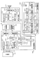
図3は、主基板31における回路構成の一例を示すブロック図である。なお、図3には、払出制御基板37、ランプドライバ基板35、音声出力基板70および演出制御基板80も示されている。主基板31には、プログラムに従ってパチンコ遊技機1を制御する基本回路53と、ゲートスイッチ32a、始動口スイッチ14a、V入賞スイッチ22、カウントスイッチ23、入賞口スイッチ29a,30a,33a,39aおよびクリアスイッチ921からの信号を基本回路53に与えるスイッチ回路58と、可変入賞球装置15を開閉するソレノイド16、開閉板20を開閉するソレノイド21および大入賞口内の経路を切り換えるためのソレノイド21Aを基本回路53からの指令に従って駆動するソレノイド回路59とが搭載されている。クリアスイッチ921は、例えば遊技機に設置されている電源基板に搭載されている。
【0037】
なお、図3には示されていないが、カウントスイッチ短絡信号もスイッチ回路58を介して基本回路53に伝達される。また、ゲートスイッチ32a、始動口スイッチ14a、V入賞スイッチ22、カウントスイッチ23、入賞口スイッチ29a,30a,33a,39a等のスイッチは、センサと称されているものでもよい。すなわち、遊技球を検出できる遊技媒体検出手段(この例では遊技球検出手段)であれば、その名称を問わない。
【0038】
また、基本回路53から与えられるデータに従って、大当りの発生を示す大当り情報、可変表示装置9における図柄の可変表示開始に利用された始動入賞球の個数を示す有効始動情報、確率変動が生じたことを示す確変情報等の情報出力信号を、遊技機裏面に設置されている情報端子盤を介してホールコンピュータ等の外部装置に対して出力する情報出力回路64が搭載されている。
【0039】
基本回路53は、ゲーム制御用のプログラム等を記憶するROM54、ワークメモリとして使用される記憶手段(変動データを記憶する手段)としてのRAM55、プログラムに従って制御動作を行うCPU56およびI/Oポート部57を含む。この実施の形態では、ROM54,RAM55はCPU56に内蔵されている。すなわち、CPU56は、1チップマイクロコンピュータである。なお、1チップマイクロコンピュータは、少なくともRAM55が内蔵されていればよく、ROM54およびI/Oポート部57は外付けであっても内蔵されていてもよい。なお、CPU56はROM54に格納されているプログラムに従って制御を実行するので、以下、CPU56が実行する(または、処理を行う)ということは、具体的には、CPU56がプログラムに従って制御を実行することである。このことは、主基板31以外の他の基板に搭載されているCPUについても同様である。
【0040】
また、RAM(CPU内蔵RAMであってもよい。)55の一部または全部が、電源基板において作成されるバックアップ電源によってバックアップされているバックアップRAMである。すなわち、遊技機に対する電力供給が停止しても、所定期間は、RAM55の一部または全部の内容は保存される。
【0041】
この実施の形態では、演出制御基板80に搭載されている演出制御手段が、遊技盤に設けられている普通図柄始動記憶表示器41および飾りランプ25等の表示制御を行うとともに、枠側に設けられている天枠ランプ28a、左枠ランプ28b、右枠ランプ28c、賞球ランプ51および球切れランプ52の表示制御を行う。なお、各ランプはLEDその他の種類の発光体でもよい。すなわち、ランプやLEDは発光体の一例であり、以下、ランプ・LEDと総称することがある。また、可変表示装置9の上部および左右部には、可変表示装置飾りLED(センター飾りLED)が設置され、大入賞口の内部には大入賞口内飾りLEDが設置され、大入賞口の左右には、大入賞口左飾りLEDおよび大入賞口右飾りLEDが設置されている。演出制御手段は、それらの発光体の制御も行う。
【0042】
なお、ランプ・LEDを駆動するための駆動信号は、ランプドライバ基板35において作成される。また、遊技機に演出手段としての可動部材が設置されている場合には、可動部材を駆動するためのモータやソレノイド等の演出用駆動手段61を駆動するための駆動信号も、ランプドライバ基板35において作成される。
【0043】
また、特別図柄を可変表示する可変表示装置9および普通図柄を可変表示する普通図柄表示器10の表示制御は、演出制御基板80に搭載されている演出制御手段によって行われる。
【0044】
さらに、演出制御基板80に搭載されている演出制御手段は人体センサの出力にもとづいて所定の演出を実行する。
【0045】
図4は、演出制御基板80、ランプドライバ基板35および音声出力基板70の回路構成例を示すブロック図である。演出制御基板80において、演出制御用CPU101は、ROM(図示せず)に格納されたプログラムに従って動作し、主基板31からのストローブ信号(演出制御INT信号)に応じて、入力ドライバ102および入力ポート103を介して演出制御コマンドを受信する。また、演出制御用CPU101は、出力ポート104およびLCD駆動回路106を介してLCDを用いた可変表示装置9の表示制御を行うとともに、出力ポート104およびランプ駆動回路107を介して普通図柄表示器10の表示制御を行う。
【0046】
さらに、演出制御用CPU101は、出力ポート104および出力ドライバ110を介して音声出力基板70に対して音番号データを出力する。また、演出制御用CPU101に入出力するバス(アドレスバス、データバス、および書込/読出信号等の制御信号ラインを含む)はバスドライバ/レシーバ(バストランシーバ)105を介してランプドライバ基板35まで延長されている。
【0047】
ランプドライバ基板35において、演出制御用CPU101に入出力するバスは、バストランシーバ351を介して出力ポート352および拡張ポート353に接続される。出力ポート352から出力される各ランプを駆動する信号は、ランプドライバ354で増幅され各ランプに供給される。また、出力ポート352から出力される各LEDを駆動する信号は、LED駆動回路355で増幅され各LEDに供給される。そして、演出用駆動手段61を駆動する信号は、駆動回路356で増幅され各ランプに供給される。
【0048】
さらに、発光部17a,17bを発光させるための駆動信号が、出力ポート352および駆動回路357を介して発光部17a,17bに出力される。また、受光部19a,19bからの信号は、増幅回路358および入力ポート359を介して入力され、バストランシーバ351を介して演出制御基板80に伝達される。なお、受光部19a,19bの出力信号が人体センサの出力信号に相当する。
【0049】
この実施の形態では、遊技機に設けられているランプ・LED、人体センサおよび演出用駆動手段は、演出制御基板80に搭載されている演出用CPU101を含む演出制御手段によって制御される。また、可変表示装置9、普通図柄表示器10およびランプ・LED等を制御するためのデータがROMに格納されている。演出用CPU101は、ROMに格納されているデータにもとづいて可変表示装置9、普通図柄表示器10およびランプ・LED等を制御する。そして、ランプドライバ基板35に搭載されている出力ポート352および各駆動回路を介して、ランプ・LEDおよび演出用駆動手段が駆動される。従って、機種変更を行う場合に、演出制御基板80を新たな機種のものに交換すれば、ランプドライバ基板35を交換せずに機種変更を実現することができる。
【0050】
なお、演出制御基板80、ランプドライバ基板35および音声出力基板70は独立した基板であるが、それらは、例えば、遊技機裏面において、1つのボックスに収容された状態で設置される。また、拡張ポート353は、機種変更を行う場合に、ランプ・LED等の数が増加した場合を考慮して設置されるが、設置されていなくてもよい。演出用の可動部材等が存在しない場合には駆動回路356は設けられなくてもよいが、機種変更を行う場合に、演出用の可動部材等が設置された場合を考慮すると、演出用の可動部材等が存在しない場合にも設けられていることが好ましい。
【0051】
音声出力基板70において、演出制御基板80からの音番号データは、入力ドライバ702を介して、例えばデジタルシグナルプロセッサによる音声合成用IC703に入力される。音声合成用IC703は、音番号データに応じたデータを音声データROM704から読み出し、読み出したデータに応じた音声や効果音を発生し増幅回路705に出力する。増幅回路705は、音声合成用IC703の出力レベルを、ボリューム706で設定されている音量に応じたレベルに増幅した音声信号をスピーカ27に出力する。
【0052】
音声データROM704に格納されている音番号データに応じたデータは、所定期間(例えば特別図柄の変動期間)における効果音または音声の出力態様を時系列的に示すデータの集まりである。音声合成用IC703は、音番号データを入力すると、音声データROM704内の対応するデータに従って音出力制御を行う。対応するデータに従った音出力制御は、次の音番号データを入力するまで継続される。そして、音声合成用IC703は、次の音番号データを入力すると、新た入力した音番号データに対応した音声データROM704内のデータに従って音出力制御を行う。
【0053】
この実施の形態では、スピーカ27から出力される音声や効果音は演出制御用CPU101を含む演出制御手段によって制御されるのであるが、演出制御手段は、音声出力基板70に音番号データを出力する。音声出力基板70において、音声データROM704には、遊技の進行に伴って出現しうる音声や効果音を実現するための多数のデータが格納され、それらのデータは音番号データに対応付けられている。従って、演出制御手段は、音番号データを出力するだけで音出力制御を実現することができる。なお、音番号データは例えば1バイトデータであり、シリアル信号線またはパラレル信号線によって音声出力基板70に転送される。
【0054】
また、演出制御手段を搭載した演出制御基板80と、演出制御基板80から出力される信号にもとづいて、演出手段を動作させるための動作信号を生成するドライバ基板(ドランプライバ基板35および音声出力基板70)とを別個に備えた構成であるから、ドライバ基板のみを交換するだけで機種変更を行うことが可能になる。そして、演出制御手段は演出制御用CPU101を含み、ドライバ基板に、演出制御用CPU101とバス接続され、選択手段からの選択入力を取り込むための入力ポート359を搭載したので、演出制御基板80の汎用性をより高めることができる。さらに、例えば、選択手段が存在しない機種では、入力ポート359を搭載しないドライバ基板に交換すればよく、演出制御基板80を交換する必要はない。
【0055】
図5は、遊技者が選択入力を入力するための選択手段としての人体センサの作用を説明するための説明図である。人体センサを構成する発光部17a,17bからの光は、ガラス扉枠2に設置されたガラスを透過する。しかし、ガラスにおける発光部17a,17bからの光の透過部に、光を反射可能な遮蔽物があると、光は遮蔽物で反射され、受光部19a,19bに到達する。従って、例えば遊技者が遮蔽物としての指等をタッチ部(発光部17a,17bからの光を反射する部分)161a,161bに当てると、受光部19a,19bに光が到達する。すなわち、受光部19a,19bに光が到達したことによって指が当てられたことが検出される。なお、受光部19a,19bの感度は、ガラスの外からの光を感知せず、発光部17a,17bからの光の遮蔽物による反射光を感知するように設定される。
【0056】
タッチ部161a,161bは、後述するように、可変表示部150において選択画面(全画面のうちの一部であって、選択のための情報が表示される部分)に相当する位置になるように設定される。つまり、選択画面に相当する位置で光が反射するように、発光部17a,17bおよび受光部19a,19bの光軸が調整される。
【0057】
なお、図5に示す構造の人体センサは一例であって、ガラスにおけるタッチ部161a,161bに遊技者の指等が当てられたことを検知できるのであれば、どのような構造の人体センサを用いてもよい。
【0058】
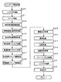
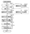
次に遊技機の動作について説明する。図6は、主基板31における遊技制御手段(CPU56およびROM,RAM等の周辺回路)が実行するメイン処理を示すフローチャートである。遊技機に対して電源が投入され、リセット端子の入力レベルがハイレベルになると、CPU56は、ステップS1以降のメイン処理を開始する。メイン処理において、CPU56は、まず、必要な初期設定を行う。
【0059】
初期設定処理において、CPU56は、まず、割込禁止に設定する(ステップS1)。次に、割込モードを割込モード2に設定し(ステップS2)、スタックポインタにスタックポインタ指定アドレスを設定する(ステップS3)。そして、内蔵デバイスレジスタの初期化を行う(ステップS4)。また、内蔵デバイス(内蔵周辺回路)であるCTC(カウンタ/タイマ)およびPIO(パラレル入出力ポート)の初期化(ステップS5)を行った後、RAMをアクセス可能状態に設定する(ステップS6)。
【0060】
この実施の形態で用いられるCPU56は、I/Oポート(PIO)およびタイマ/カウンタ回路(CTC)も内蔵している。また、CTCは、2本の外部クロック/タイマトリガ入力CLK/TRG2,3と2本のタイマ出力ZC/TO0,1を備えている。
【0061】
この実施の形態で用いられているCPU56には、マスク可能な割込のモードとして以下の3種類のモードが用意されている。なお、マスク可能な割込が発生すると、CPU56は、自動的に割込禁止状態に設定するとともに、プログラムカウンタの内容をスタックにセーブする。
【0062】
割込モード0:割込要求を行った内蔵デバイスがRST命令(1バイト)またはCALL命令(3バイト)をCPUの内部データバス上に送出する。よって、CPU56は、RST命令に対応したアドレスまたはCALL命令で指定されるアドレスの命令を実行する。リセット時に、CPU56は自動的に割込モード0になる。よって、割込モード1または割込モード2に設定したい場合には、初期設定処理において、割込モード1または割込モード2に設定するための処理を行う必要がある。
【0063】
割込モード1:割込が受け付けられると、常に0038(h)番地に飛ぶモードである。
【0064】
割込モード2:CPU56の特定レジスタ(Iレジスタ)の値(1バイト)と内蔵デバイスが出力する割込ベクタ(1バイト:最下位ビット0)から合成されるアドレスが、割込番地を示すモードである。すなわち、割込番地は、上位アドレスが特定レジスタの値とされ下位アドレスが割込ベクタとされた2バイトで示されるアドレスである。従って、任意の(飛び飛びではあるが)偶数番地に割込処理を設置することができる。各内蔵デバイスは割込要求を行うときに割込ベクタを送出する機能を有している。
【0065】
よって、割込モード2に設定されると、各内蔵デバイスからの割込要求を容易に処理することが可能になり、また、プログラムにおける任意の位置に割込処理を設置することが可能になる。さらに、割込モード1とは異なり、割込発生要因毎のそれぞれの割込処理を用意しておくことも容易である。上述したように、この実施の形態では、初期設定処理のステップS2において、CPU56は割込モード2に設定される。
【0066】
次いで、CPU56は、入力ポートを介して入力されるクリアスイッチ921の出力信号の状態を1回だけ確認する(ステップS7)。その確認においてオンを検出した場合には、CPU56は、通常の初期化処理を実行する(ステップS11〜ステップS14)。
【0067】
クリアスイッチ921がオンの状態でない場合には、遊技機への電力供給が停止したときにバックアップRAM領域のデータ保護処理(例えばパリティデータの付加等の電力供給停止時処理)が行われたか否か確認する(ステップS8)。そのような保護処理が行われていないことを確認したら、CPU56は初期化処理を実行する。バックアップRAM領域にバックアップデータがあるか否かは、例えば、電力供給停止時処理においてバックアップRAM領域に設定されるバックアップフラグの状態によって確認される。この例では、バックアップフラグ領域に「55H」が設定されていればバックアップあり(オン状態)を意味し、「55H」以外の値が設定されていればバックアップなし(オフ状態)を意味する。
【0068】
バックアップありを確認したら、CPU56は、バックアップRAM領域のデータチェック(この例ではパリティチェック)を行う(ステップS9)。ステップS9では、算出したチェックサムと、電力供給停止時処理にて同一の処理によって算出され保存されているチェックサムとを比較する。不測の停電等の電力供給停止が生じた後に復旧した場合には、バックアップRAM領域のデータは保存されているはずであるから、チェック結果(比較結果)は正常(一致)になる。チェック結果が正常でないということは、バックアップRAM領域のデータが、電力供給停止時のデータとは異なっていることを意味する。そのような場合には、内部状態を電力供給停止時の状態に戻すことができないので、電力供給の停止からの復旧時でない電源投入時に実行される初期化処理を実行する。
【0069】
チェック結果が正常であれば、CPU56は、遊技制御手段の内部状態と演出制御手段等の電気部品制御手段の制御状態を電力供給停止時の状態に戻すための遊技状態復旧処理を行う(ステップS10)。そして、バックアップRAM領域に保存されていたPC(プログラムカウンタ)の退避値がPCに設定され、そのアドレスに復帰する。
【0070】
なお、この実施の形態では、バックアップフラグとチェックデータとの双方を用いてバックアップRAM領域のデータが保存されているか否かを確認しているが、いずれか一方のみを用いてもよい。すなわち、バックアップフラグとチェックデータとのいずれかを、状態復旧処理を実行するための契機としてもよい。
【0071】
初期化処理では、CPU56は、まず、RAMクリア処理を行う(ステップS11)。また、所定の作業領域(例えば、普通図柄判定用乱数カウンタ、普通図柄判定用バッファ、特別図柄左中右図柄バッファ、特別図柄プロセスフラグ、払出コマンド格納ポインタ、賞球中フラグ、球切れフラグ、払出停止フラグなど制御状態に応じて選択的に処理を行うためのフラグ)に初期値を設定する作業領域設定処理を行う(ステップS12)。さらに、サブ基板(この実施の形態では払出制御基板35および演出制御基板80)を初期化するための初期化コマンドを各サブ基板に送信する処理を実行する(ステップS13)。初期化コマンドとして、可変表示装置9に表示される初期図柄を示すコマンド(演出制御基板80に対して)や賞球ランプ51および球切れランプ52の消灯を指示するコマンド等がある。
【0072】
そして、2ms毎に定期的にタイマ割込がかかるようにCPU56に設けられているCTCのレジスタの設定が行われる(ステップS14)。すなわち、初期値として2msに相当する値が所定のレジスタ(時間定数レジスタ)に設定される。
【0073】
初期化処理の実行(ステップS11〜S14)が完了すると、メイン処理で、表示用乱数更新処理(ステップS17)および初期値用乱数更新処理(ステップS18)が繰り返し実行される。表示用乱数更新処理および初期値用乱数更新処理が実行されるときには割込禁止状態とされ(ステップS16)、表示用乱数更新処理および初期値用乱数更新処理の実行が終了すると割込許可状態とされる(ステップS19)。表示用乱数とは、可変表示装置9に表示される図柄を決定するための乱数であり、表示用乱数更新処理とは、表示用乱数を発生するためのカウンタのカウント値を更新する処理である。また、初期値用乱数更新処理とは、初期値用乱数を発生するためのカウンタのカウント値を更新する処理である。初期値用乱数とは、大当りとするか否かを決定するための乱数を発生するためのカウンタ(大当り決定用乱数発生カウンタ)等のカウント値の初期値を決定するための乱数である。後述する遊技制御処理において、大当り決定用乱数発生カウンタのカウント値が1周すると、そのカウンタに初期値が設定される。
【0074】
なお、表示用乱数更新処理が実行されるときには割込禁止状態とされるのは、表示用乱数更新処理が後述するタイマ割込処理でも実行されることから、タイマ割込処理における処理と競合してしまうのを避けるためである。すなわち、ステップS17の処理中にタイマ割込が発生してタイマ割込処理中で表示用乱数を発生するためのカウンタのカウント値を更新してしまったのでは、カウント値の連続性が損なわれる場合がある。しかし、ステップS17の処理中では割込禁止状態にしておけば、そのような不都合が生ずることはない。
【0075】
タイマ割込が発生すると、CPU56は、レジスタの退避処理(ステップS20)を行った後、図7に示すステップS21〜S33の遊技制御処理を実行する。遊技制御処理において、CPU56は、まず、スイッチ回路58を介して、ゲートスイッチ32a、始動口スイッチ14a、カウントスイッチ23および入賞口スイッチ24a等のスイッチの検出信号を入力し、それらの状態判定を行う(スイッチ処理:ステップS21)。
【0076】
次に、遊技制御に用いられる大当り判定用の乱数等の各判定用乱数を生成するための各カウンタのカウント値を更新する処理を行う(ステップS22)。CPU56は、さらに、初期値用乱数を生成するためのカウンタのカウント値を更新する処理および表示用乱数を生成するためのカウンタのカウント値を更新する処理を行う(ステップS23,S24)。
【0077】
図8は、各乱数を示す説明図である。各乱数を示す説明図である。各乱数は、以下のように使用される。
(1)ランダム1:大当りを発生させるか否か決定する(大当り判定用)
(2)ランダム2−1〜2−3(ランダム2):特別図柄の左中右のはずれ図柄決定用(特別図柄左中右)
(3)ランダム3:大当りを発生させる特別図柄の組合せを決定する(大当り図柄決定用)
(4)ランダム4:特別図柄の変動パターンを決定する(変動パターン決定用)
(5)ランダム5:大当りを発生させない場合にリーチとするか否かを決定する(リーチ判定用)
(6)ランダム6:普通図柄にもとづく当りを発生させるか否か決定する(普通図柄当り判定用)
(7)ランダム7:ランダム1の初期値を決定する(ランダム1初期値決定用)
(8)ランダム8:ランダム6の初期値を決定する(ランダム6初期値決定用)
【0078】
図7に示された遊技制御処理におけるステップS22では、CPU56は、(1)の大当り判定用乱数、(3)の大当り図柄決定用乱数、および(6)の普通図柄当り判定用乱数を生成するためのカウンタのカウントアップ(1加算)を行う。すなわち、それらが判定用乱数であり、それら以外の乱数が表示用乱数または初期値用乱数である。なお、遊技効果を高めるために、上記(1)〜(8)の乱数以外の普通図柄に関する乱数等も用いられている。
【0079】
なお、この実施の形態では、左中右図柄が揃って停止すると、すなわち左中右図柄の確定図柄が一致すると大当りとなり、左右図柄が揃って停止すると、すなわち左右図柄の確定図柄が一致するとリーチとなる。また、大当りとする場合、左中右図柄が奇数の図柄であれば確変状態(高確率状態)に移行する。
【0080】
さらに、CPU56は、特別図柄プロセス処理を行う(ステップS25)。特別図柄プロセス制御では、遊技状態に応じてパチンコ遊技機1を所定の順序で制御するための特別図柄プロセスフラグに従って該当する処理が選び出されて実行される。そして、特別図柄プロセスフラグの値は、遊技状態に応じて各処理中に更新される。また、普通図柄プロセス処理を行う(ステップS26)。普通図柄プロセス処理では、普通図柄表示器10の表示状態を所定の順序で制御するための普通図柄プロセスフラグに従って該当する処理が選び出されて実行される。そして、普通図柄プロセスフラグの値は、遊技状態に応じて各処理中に更新される。
【0081】
次いで、CPU56は、特別図柄に関する演出制御コマンドをRAM55の所定の領域に設定して演出制御コマンドを送出する処理を行う(特別図柄コマンド制御処理:ステップS27)。また、普通図柄に関する演出制御コマンドをRAM55の所定の領域に設定して演出制御コマンドを送出する処理を行う(普通図柄コマンド制御処理:ステップS28)。
【0082】
さらに、CPU56は、例えばホール管理用コンピュータに供給される大当り情報、始動情報、確率変動情報などのデータを出力する情報出力処理を行う(ステップS29)。
【0083】
また、CPU56は、入賞口スイッチ29a,30a,33a,39aの検出信号にもとづく賞球個数の設定などを行う賞球処理を実行する(ステップS30)。具体的には、入賞口スイッチ29a,30a,33a,39aの何れかがオンしたことにもとづく入賞検出に応じて、払出制御基板37に賞球個数を示す払出制御コマンドを出力する。払出制御基板37に搭載されている払出制御用CPUは、賞球個数を示す払出制御コマンドに応じて球払出装置97を駆動する。
【0084】
そして、CPU56は、始動入賞記憶数の増減をチェックする記憶処理を実行する(ステップS31)。また、遊技機の制御状態を遊技機外部で確認できるようにするための試験信号を出力する処理である試験端子処理を実行する(ステップS32)。さらに、所定の条件が成立したときにソレノイド回路59に駆動指令を行う(ステップS33)。可変入賞球装置15または開閉板20を開状態または閉状態としたり、大入賞口内の遊技球通路を切り替えたりするために、ソレノイド回路59は、駆動指令に応じてソレノイド16,21,21Aを駆動する。その後、レジスタの内容を復帰させ(ステップS34)、割込許可状態に設定する(ステップS35)。
【0085】
以上の制御によって、この実施の形態では、遊技制御処理は2ms毎に起動されることになる。なお、この実施の形態では、タイマ割込処理で遊技制御処理が実行されているが、タイマ割込処理では例えば割込が発生したことを示すフラグのセットのみがなされ、遊技制御処理はメイン処理において実行されるようにしてもよい。
【0086】
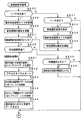
図9は、CPU56が実行する特別図柄プロセス処理のプログラムの一例を示すフローチャートである。図9に示す特別図柄プロセス処理は、図7のフローチャートにおけるステップS25の具体的な処理である。CPU56は、特別図柄プロセス処理を行う際に、変動短縮タイマ減算処理(ステップS310)を行い、遊技盤6に設けられている始動入賞口14に遊技球が入賞したことを検出するための始動口スイッチ14aがオンしていたら、すなわち遊技球が始動入賞口14に入賞する始動入賞が発生していたら(ステップS311)、始動口スイッチ通過処理(ステップS312)を行った後に、内部状態に応じて、ステップS300〜S308のうちのいずれかの処理を行う。変動短縮タイマは、特別図柄の変動時間が短縮される場合に、変動時間を設定するためのタイマである。
【0087】
特別図柄通常処理(ステップS300):特別図柄の可変表示を開始できる状態になるのを待つ。特別図柄の可変表示が開始できる状態になると、始動入賞記憶数を確認する。始動入賞記憶数が0でなければ、特別図柄の可変表示の結果、大当りとするか否か決定する。そして、内部状態(特別図柄プロセスフラグ)をステップS301に移行するように更新する。
【0088】
特別図柄停止図柄設定処理(ステップS301):特別図柄の可変表示後の左中右図柄の停止図柄を決定する。そして、内部状態(特別図柄プロセスフラグ)をステップS302に移行するように更新する。
【0089】
変動パターン設定処理(ステップS302):特別図柄の可変表示の変動パターン(可変表示態様)を、ランダム4の値に応じて決定する。また、変動時間タイマをスタートさせる。このとき、演出制御基板80に対して、左中右最終停止図柄と変動態様(変動パターン)を指令する情報とが送信される。そして、内部状態(特別図柄プロセスフラグ)をステップS303に移行するように更新する。
【0090】
特別図柄変動処理(ステップS303):所定時間(ステップS302の変動時間タイマで示された時間)が経過すると、内部状態(特別図柄プロセスフラグ)をステップS304に移行するように更新する。
【0091】
特別図柄停止処理(ステップS304):可変表示装置9において表示される全図柄が停止されるように制御する。具体的には、特別図柄停止を示す演出制御コマンドが送信される状態に設定する。そして、停止図柄が大当り図柄の組み合わせである場合には、内部状態(特別図柄プロセスフラグ)をステップS305に移行するように更新する。そうでない場合には、内部状態をステップS300に移行するように更新する。
【0092】
大入賞口開放開始処理(ステップS305):大入賞口を開放する制御を開始する。具体的には、カウンタやフラグを初期化するとともに、ソレノイド21を駆動して大入賞口を開放する。また、プロセスタイマによって大入賞口開放中処理の実行時間を設定し、大当り中フラグをセットする。そして、内部状態(特別図柄プロセスフラグ)をステップS306に移行するように更新する。
【0093】
大入賞口開放中処理(ステップS306):大入賞口ラウンド表示の演出制御コマンドを演出制御基板80に送出する制御や大入賞口の閉成条件の成立を確認する処理等を行う。最後の大入賞口の閉成条件が成立したら、内部状態をステップS307に移行するように更新する。
【0094】
特定領域有効時間処理(ステップS307):V入賞スイッチ22の通過の有無を監視して、大当り遊技状態継続条件の成立を確認する処理を行う。大当り遊技状態継続の条件が成立し、かつ、まだ残りラウンドがある場合には、内部状態をステップS305に移行するように更新する。また、所定の有効時間内に大当り遊技状態継続条件が成立しなかった場合、または、全てのラウンドを終えた場合には、内部状態をステップS308に移行するように更新する。
【0095】
大当り終了処理(ステップS308):大当り遊技状態が終了したことを遊技者に報知する表示制御を演出制御手段に行わせるための制御を行う。そして、内部状態をステップS300に移行するように更新する。
【0096】
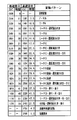
図10は、この実施の形態で用いられる変動パターンの一例を示す説明図である。図10において、「EXT」とは、2バイト構成(MODEデータとEXTデータ)の演出制御コマンドにおける2バイト目のEXTデータを示す。なお、この実施の形態では、1バイト目の「MODE」データは、いずれの場合も「80(H)」である。また、「時間」は特別図柄の変動時間(識別情報の可変表示期間)を示す。図10に示すように、高確率中(確変中)では、各変動パターンの変動時間が3.5秒短くなっている。
【0097】
なお、「通常変動」とは、リーチ態様を伴わない変動パターンである。「ノーマル」とは、リーチ態様を伴うが変動結果(停止図柄)が大当りを生じさせるものとならない変動パターンである。「リーチA」は、「ノーマル」とは異なるリーチ態様を持つ変動パターンである。リーチ態様が異なるとは、リーチ演出を行っている期間において異なった態様の変動態様(速度や回転方向等)やキャラクタ等が現れることをいう。例えば、「ノーマル」では単に1種類の変動態様によってリーチ態様が実現されるのに対して、「リーチA」では、変動速度や変動方向が異なる複数の変動態様を含むリーチ態様が実現される。
【0098】
また、「リーチB」は、「ノーマル」および「リーチA」とは異なるリーチ態様を持つ変動パターンである。「リーチC」は、「ノーマル」、「リーチA」および「リーチB」とは異なるリーチ態様を持つ変動パターンである。「リーチD」は、「ノーマル」、「リーチA」、「リーチB」および「リーチC」とは異なるリーチ態様を持つ変動パターンである。そして、「全回転」は、左右中図柄が揃って変動するようなリーチ態様を含む変動パターンである。
【0099】
「選択演出付き」とは、後述する選択演出を伴う変動パターンである。「当り」は図柄の変動終了後に大当りが発生することを示す。「再」は、いわゆる仮停止後の再変動態様が現れることを示す。「戻り」は、停止図柄が停止位置を一旦過ぎた後に逆変動して停止する変動態様を含むことを示す。
【0100】
この実施の形態では、さらに、短縮表示パターンが用いられる。短縮表示パターンは、左中右の図柄の変動時間が例えば1.0秒という極めて短い変動パターンである。
【0101】
図11は、主基板31の遊技制御手段による変動パターンの振り分け方を示す説明図である。遊技制御手段は、図8に示したように、ランダム4(0〜149の150種類の値をとりうる乱数)に応じて変動パターンを決定するのであるが、大当りとすることに決定した場合には、図11に示す「あたり」の欄に記載されているような振り分け方で変動パターンを決定する。例えば、非確変時(低確率中)には、ランダム4の値が、演出制御コマンド「8008(H)」の変動パターン(図10より「リーチC・選択演出付き・当り」)に対応してあらかじめ決められている値に一致したら、演出制御コマンド「8008(H)」の変動パターンを用いることに決定する。なお、「8008(H)」の変動パターンに対応してあらかじめ決められている値として12個の値が定められている(図11参照)。
【0102】
図12は始動口スイッチ通過処理(ステップS312)を示すフローチャートである。始動口スイッチ通過処理において、CPU56は、始動入賞記憶数が最大値である4に達しているかどうか確認する(ステップS111)。始動入賞記憶数が4に達していなければ、始動入賞記憶数を1増やし(ステップS112)、大当り判定用乱数等の各乱数の値を抽出し、それらを始動入賞記憶数の値に対応した保存領域(特別図柄判定用バッファ)に格納する(ステップS113)。なお、乱数を抽出するとは、乱数を生成させるためのカウンタからカウント値を読み出して、読み出したカウント値を乱数値とすることである。ステップS114では、図8に示された乱数のうち、ランダム1〜ランダム5が抽出される。
【0103】
図13は、特別図柄プロセス処理における特別図柄通常処理(ステップS300)を示すフローチャートである。特別図柄通常処理において、CPU56は、特別図柄の変動を開始することができる状態(例えば特別図柄プロセスフラグの値がステップS300を示す値となっている場合)には(ステップS51)、始動入賞記憶数の値を確認する(ステップS52)。具体的には、始動入賞カウンタのカウント値を確認する。なお、特別図柄プロセスフラグの値がステップS300を示す値となっている場合とは、可変表示装置9において図柄の変動がなされていず、かつ、大当り遊技中でもない場合である。
【0104】
始動入賞記憶数が0でなければ、始動入賞記憶数=1に対応する保存領域に格納されている各乱数値を読み出してRAM55の乱数バッファ領域に格納するとともに(ステップS53)、始動入賞記憶数の値を1減らし、かつ、各保存領域の内容をシフトする(ステップS54)。すなわち、始動入賞記憶数=n(n=2,3,4)に対応する保存領域に格納されている各乱数値を、始動入賞記憶数=n−1に対応する保存領域に格納する。
【0105】
次いで、CPU56は、乱数格納バッファから大当り判定用乱数を読み出し(ステップS55)、大当り判定処理を実行する(ステップS56)。大当り判定処理で大当りとすることに決定した場合には(ステップS57)、CPU56は、大当りフラグをセットする(ステップS58)。そして、特別図柄プロセスフラグの値を特別図柄停止図柄設定処理に対応した値に更新する(ステップS59)。
【0106】
図14は、特別図柄プロセス処理における特別図柄停止図柄設定処理(ステップS301)を示すフローチャートである。特別図柄停止図柄設定処理において、CPU56は、大当りフラグがセットされているか否か確認する(ステップS61)。大当りフラグがセットされている場合には、大当り図柄用乱数(ランダム3)の値(ステップS53において読み出したランダム3)に従って大当り図柄を決定する(ステップS62)。この実施の形態では、ランダム3の値に応じた大当り図柄テーブルに設定されている図柄番号の各図柄が、大当り図柄として決定される。大当り図柄テーブルには、複数種類の大当り図柄の組み合わせのそれぞれに対応した左中右の図柄番号が設定されている。そして、特別図柄プロセスフラグの値を変動パターン設定処理に対応した値に更新する(ステップS63)。
【0107】
大当りフラグがセットされていない場合には、CPU56は、リーチ判定処理を実行する(ステップS65)。ここでは、リーチ判定処理において、ステップS53で保存領域から読み出したランダム3の値すなわち乱数値バッファに格納されている値にもとづいてリーチとするか否かの決定が行われる(ステップS64)。また、ランダム2−1の値に従って左右図柄を決定し、ランダム2−2の値に従って中図柄を決定する(ステップS67)。ここで、決定された中図柄が左右図柄と一致した場合には、中図柄に対応した乱数の値に1加算した値に対応する図柄を中図柄の停止図柄として、大当り図柄と一致しないようにする。そして、ステップS63に移行する。
【0108】
ステップS66においてリーチしないことに決定された場合には、はずれの場合の停止図柄の決定を行う(ステップS68)。具体的には、ステップS53で読み出した値、すなわち抽出されているランダム2−1の値に従って左図柄を決定し、ランダム2−2の値に従って中図柄を決定するとともに、ランダム2−3の値に従って右図柄を決定する。なお、ここでは、左右図柄が一致した場合には右図柄を1図柄ずらし、リーチにもならないはずれとなるようにする。そして、ステップS63に移行する。なお、ステップS62において確変図柄が決定された場合には、大当り遊技の終了後に確変状態に移行することを示す確変フラグがセットされる。
【0109】
次に、遊技制御手段から演出制御手段に対する制御コマンドの送出方式について説明する。図15は、主基板31から演出制御基板80に送信される演出制御コマンドの信号線を示す説明図である。図15に示すように、この実施の形態では、演出制御コマンドは、演出制御信号D0〜D7の8本の信号線で主基板31から演出制御基板80に送信される。また、主基板31と演出制御基板80との間には、ストローブ信号(演出制御INT信号)を送信するための演出制御INT信号の信号線も配線されている。なお、図15には、演出制御コマンドの例が示されているが、他の電気部品制御基板(この実施の形態では払出制御手段)への制御コマンドも、8本の信号線と1本のINT信号の信号線によって送信される。
【0110】
この実施の形態では、演出制御コマンドは2バイト構成であり、1バイト目はMODE(コマンドの分類)を表し、2バイト目はEXT(コマンドの種類)を表す。MODEデータの先頭ビット(ビット7)は必ず「1」とされ、EXTデータの先頭ビット(ビット7)は必ず「0」とされる。なお、そのようなコマンド形態は一例であって他のコマンド形態を用いてもよい。例えば、1バイトや3バイト以上で構成される制御コマンドを用いてもよい。
【0111】
図16に示すように、演出制御コマンドの8ビットの演出制御コマンドデータは、演出制御INT信号に同期して出力される。演出制御基板80に搭載されている演出制御手段は、演出制御INT信号が立ち上がったことを検知して、割込処理によって1バイトのデータの取り込み処理を開始する。従って、演出制御手段から見ると、演出制御INT信号は、演出制御コマンドデータの取り込みの契機となる取込信号に相当する。
【0112】
演出制御コマンドは、演出制御手段が認識可能に1回だけ送出される。認識可能とは、この例では、演出制御INT信号のレベルが変化することであり、認識可能に1回だけ送出されるとは、例えば演出制御コマンドデータの1バイト目および2バイト目のそれぞれに応じて演出制御INT信号が1回だけパルス状(矩形波状)に出力されることである。なお、演出制御INT信号は図16に示された極性と逆極性であってもよい。
【0113】
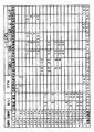
図17は、演出制御基板80に送出される演出制御コマンドの内容の一例を示す説明図である。図17に示す例において、コマンド8000(H)〜8026(H)は、特別図柄を可変表示する可変表示装置9における特別図柄の変動パターンを指定する演出制御コマンドである。なお、変動パターンを指定するコマンド(変動パターンコマンド)は変動開始指示も兼ねている。また、コマンド8000(H)〜8012(H)は低確率中(非確変時)において用いられ、コマンド8013(H)〜8025(H)は高確率中(確変時)において用いられる。そして、コマンド8026(H)は、短縮表示パターンを指定するコマンドである。
【0114】
コマンド88XX(H)(X=4ビットの任意の値)は、普通図柄表示器10で可変表示される普通図柄の変動パターンに関する演出制御コマンドである。コマンド89XX(H)は、普通図柄の停止図柄を指定する演出制御コマンドである。コマンド8AXX(H)(X=4ビットの任意の値)は、普通図柄の可変表示の停止を指示する演出制御コマンドである。
【0115】
コマンド91XX(H)、92XX(H)および93XX(H)は、特別図柄の左中右の停止図柄を指定する演出制御コマンドである。「XX」には図柄番号が設定される。また、コマンドA000(H)は、特別図柄の可変表示の停止を指示する演出制御コマンドである。コマンドBXXX(H)は、大当り遊技開始から大当り遊技終了までの間に送出される演出制御コマンドである。そして、コマンドC000(H)〜EXXX(H)は、特別図柄の変動および大当り遊技に関わらない可変表示装置9の表示状態に関する演出制御コマンドである。
【0116】
コマンドE0XX(H)は、可変表示装置9における始動入賞記憶数を表示する表示エリアにおいて、表示色を変化させる始動記憶表示エリア18の個数を示す演出制御コマンドである。例えば、演出制御手段は、各始動記憶表示エリア18のうち「XX(H)」で指定される個数の始動記憶表示エリア18の表示色を変化させる。すなわち、コマンドE0XX(H)は、保留個数という情報を報知するために設けられている表示エリアの制御を指示するコマンドである。なお、表示色を変化させる始動記憶表示エリア18の個数に関するコマンドが、表示色を変化させるエリアの個数の増減を示すように構成されていてもよい。また、この実施の形態では、始動入賞記憶の上限値は4であるから、「XX」は0〜4のいずれかである。
【0117】
また、コマンドE400(H)は、高確率状態から低確率状態になったときに送信されるコマンドであり、コマンドE401(H)は、低確率状態から高確率状態になったときに送信されるコマンドである。
【0118】
演出制御基板80の演出制御手段は、主基板31の遊技制御手段から上述した演出制御コマンドを受信すると図17に示された内容に応じて可変表示装置9および普通図柄表示器10の表示状態を変更するとともに、ランプ・LEDの表示状態を変更し、必要ならば音声出力基板70に対して音番号データを出力する。なお、図17に示された例以外の制御コマンドも遊技制御手段から演出制御手段に送信される。例えば、賞球ランプ51や球切れランプ52の表示状態、および普通図柄始動記憶表示器41の点灯個数を示す制御コマンド等や、大当り遊技に関するより詳細な演出制御コマンドも遊技制御手段から演出制御手段に送信される。
【0119】
可変表示の開始を示す可変表示開始指定コマンドおよび可変表示態様を特定可能な可変表示態様指定コマンドは、変動パターン指定の演出制御コマンドで実現され、識別情報の表示結果を特定可能な識別情報指定コマンドは、左図柄指定、中図柄指定、右図柄指定の演出制御コマンドで実現され、可変表示の終了を示す可変表示終了指定コマンドは、特別図柄停止の演出制御コマンドで実現されている。また、この実施の形態では、変動パターン指定の演出制御コマンドが可変表示の開始を示す可変表示開始指定コマンドおよび可変表示態様を特定可能な可変表示態様指定コマンドとして兼用されているが、可変表示開始指定コマンドと可変表示態様を特定可能な可変表示態様指定コマンドとを別にしてもよい。
【0120】
次に、演出制御手段の動作を説明する。図18は、演出制御用CPU101が実行するメイン処理を示すフローチャートである。メイン処理では、まず、RAM領域のクリアや各種初期値の設定、また演出制御の起動間隔を決めるための2msタイマの初期設定等を行うための初期化処理が行われる(ステップS701)。その後、演出制御用CPU101は、タイマ割込フラグの監視(ステップS702)の確認を行うループ処理に移行する。タイマ割込が発生すると、演出制御用CPU101は、タイマ割込処理においてタイマ割込フラグをセットする。メイン処理において、タイマ割込フラグがセットされていたら、演出制御用CPU101は、そのフラグをクリアし(ステップS703)、以下の演出制御処理を実行する。
【0121】
この実施の形態では、タイマ割込は2ms毎にかかる。すなわち、演出制御処理は、2ms毎に起動される。また、この実施の形態では、タイマ割込処理ではフラグセットのみがなされ、具体的な演出制御処理はメイン処理において実行されるが、タイマ割込処理で演出制御処理を実行してもよい。
【0122】
演出制御処理において、演出制御用CPU101は、まず、受信した演出制御コマンドを解析する(コマンド解析実行処理:ステップS704)。次いで演出制御用CPU101は、演出制御プロセス処理を行う(ステップS705)。演出制御プロセス処理では、制御状態に応じた各プロセスのうち、現在の制御状態に対応したプロセスを選択して実行する。そして、乱数カウンタを更新する処理を実行する(ステップS706)。その後、ステップS702のタイマ割込フラグの確認を行う処理に戻る。なお、乱数カウンタのカウント値は、後述する選択演出において、いずれの態様の初期表示を行うのかを決定するために用いられる。
【0123】
次に、主基板31からの演出制御コマンド受信処理について説明する。図19は、主基板31から受信した演出制御コマンドを格納するためのコマンド受信バッファの一構成例を示す説明図である。この例では、2バイト構成の演出制御コマンドを6個格納可能なリングバッファ形式のコマンド受信バッファが用いられる。従って、コマンド受信バッファは、受信コマンドバッファ1〜12の12バイトの領域で構成される。そして、受信したコマンドをどの領域に格納するのかを示すコマンド受信個数カウンタが用いられる。コマンド受信個数カウンタは、0〜11の値をとる。なお、必ずしもリングバッファ形式でなくてもよく、例えば、図柄指定コマンド格納領域を3個(2×3=6バイトのコマンド受信バッファ)、それ以外の変動パターン指定などのコマンド格納領域を1個(2×1=2バイトのコマンド受信バッファ)のようなバッファ構成としてもよい。音声制御手段や、ランプ制御手段においても同様に、リングバッファ形式でないバッファ形式としてもよい。
【0124】
主基板31からの演出制御用のINT信号は演出制御用CPU101の割込端子に入力されている。例えば、主基板31からのINT信号がオン状態になると、演出制御用CPU101において割込がかかる。そして、演出制御用CPU101は、割込処理において演出制御コマンドの受信処理を実行する。演出制御コマンドの受信処理において、演出制御用CPU101は、受信した演出制御コマンドデータを、コマンド受信個数カウンタが示す受信コマンドバッファに格納する。
【0125】
図20は、図18に示されたメイン処理における演出制御プロセス処理(ステップS705)を示すフローチャートである。演出制御プロセス処理では、演出制御プロセスフラグの値に応じてステップS800〜S806のうちのいずれかの処理が行われる。各処理において、以下のような処理が実行される。
【0126】
変動パターンコマンド受信待ち処理(ステップS800):コマンド受信割込処理によって、変動時間を特定可能な演出制御コマンド(変動パターンコマンド)を受信したか否か確認する。具体的には、変動パターンコマンドが受信されたことを示すフラグ(変動パターン受信フラグ)がセットされたか否か確認する。変動パターン受信フラグは、コマンド解析処理によって、変動パターン指定の演出制御コマンドが受信されたことが確認された場合にセットされる(ステップS623)。
【0127】
選択演出の選択処理(ステップS801):選択演出において、いずれの態様の初期表示を行うのかを決定する。
【0128】
全図柄変動開始処理(ステップS802):左中右図柄の変動が開始されるように制御する。
【0129】
図柄変動中処理(ステップS803):変動パターンを構成する各変動状態(変動速度)の切替タイミングを制御するとともに、変動時間の終了を監視する。また、左右図柄の停止制御を行う。さらに、選択演出を行うときには、選択演出の表示態様の制御も行う。
【0130】
全図柄停止待ち設定処理(ステップS804):変動時間の終了時に、全図柄停止を指示する演出制御コマンド(特別図柄停止の演出制御コマンド)を受信していたら、図柄の変動を停止し停止図柄(確定図柄)を表示する制御を行う。
【0131】
大当り表示処理(ステップS805):変動時間の終了後、確変大当り表示または通常大当り表示の制御を行う。
【0132】
大当たり遊技中処理(ステップS806):大当たり遊技中の制御を行う。例えば、大入賞口開放前表示や大入賞口開放時表示の演出制御コマンドを受信したら、ラウンド数の表示制御等を行う。
【0133】
図21は、変動パターンテーブル毎に設定されているプロセスデータの一構成例を示す説明図である。プロセスデータは、プロセスタイマ設定値と演出制御実行データの組み合わせが複数集まったデータで構成されている。演出制御実行データは、表示制御実行データとランプ制御実行データとを含む。表示制御実行データは、特別図柄の変動期間中における可変表示装置9の表示状態を示すデータが設定されている。例えば、表示制御実行データ1には、可変表示開始時の可変表示装置9の表示状態を示すデータが設定されている。また、ランプ制御実行データは、特別図柄の変動期間中におけるランプ・LEDの表示状態を示すデータが設定されている。例えば、ランプ制御実行データ1には、可変表示開始時のランプ・LEDの表示状態を示すデータが設定されている。そして、特別図柄の変動期間中において、表示状態を切り替えるタイミング(例えば可変表示装置9において新たなキャラクタが登場するタイミング、ランプ・LEDを点灯状態から消灯状態に切り替えるタイミング)が到来すると、演出制御手段は、プロセスデータにおける次の演出制御実行データに従って、可変表示装置9およびランプ・LEDの表示状態を制御する。プロセスタイマ設定値には、切替のタイミングに応じた時間が設定されている。
【0134】
このように、演出制御手段が、ROMに記憶されているプログラムおよびプロセスデータにもとづいて演出手段を制御し、複数の演出手段(この実施の形態では可変表示装置9およびランプ・LED)の制御に関わるプログラムが、演出制御基板80に搭載されているROMに格納されている。そして、それらのプログラムを格納するROMを1つのROMとして構成することができる。従って、部品点数を減らすことができる。また、ROMに記憶されているプロセスデータのうち、プロセスタイマ設定値が共通化されている。従って、演出制御手段のROM容量を節減することができる。なお、演出制御実行データについても、表示制御実行データとランプ制御実行データとを共通化できるのであれば、1つの演出制御実行データとしてもよい。このように、この実施の形態では、複数の演出手段の制御に関わるデータのうち少なくとも一部のデータ(この実施の形態では音声データROM704に格納されているデータを除くデータ)を同一ROMに格納することができる。
【0135】
図21に示すプロセスデータは、演出制御基板80におけるROMに格納されている。また、プロセスデータは、各変動パターンのそれぞれに応じて用意されている。また、選択演出の種類に応じて用意されている。例えば、変動パターン10で一の選択演出を実行する場合のプロセスデータは、変動パターン10で他の選択演出を実行する場合のプロセスデータとは別に用意されている。
【0136】
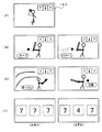
図22および図23は、選択演出の一例を示す説明図である。選択演出はリーチ演出がなされる期間において実行される。また、選択演出は、演出制御手段が遊技者に提示する複数の選択肢から一の選択肢を選択させたり、遊技者に提示する情報を選択するか否かを遊技者に決定させたりして、選択結果または決定結果に応じて、可変表示装置9、演出用のランプ・LEDおよびスピーカ27の全部または一部を用いて実行される演出である。
【0137】
図22および図23に示す例では、左中右の図柄が変動してリーチとなった後((A),(B)参照)、2種類の球種(例えばカーブとトルネード)が可変表示装置9に表示される((C)参照)。そのとき、図柄表示エリアは可変表示部150において右上方に移動している。また、可変表示部150には、選択有効期間を報知するための選択有効期間表示領域162も表示されている。選択有効期間において遊技者がいずれかを選択すると、選択された方の球種の輝度が上がるとともに、「これでよいですか?」の表示がなされる((D)参照)。また、いずれかが選択された後、他方の選択がなされると他方の輝度が上がるとともに、既に選択されていた方の輝度が元に戻る。また、再度「これでよいですか?」の表示がなされる。そして、選択有効期間が終了すると、最後に選択された球種のみが表示される((E)参照)。
【0138】
なお、この実施の形態では、可変表示部150に選択有効期間表示領域162を画像表示するが、例えば「選んでください」の表示開始時期(図22(C)参照)から「これでよいですか?」の表示開始時期(図22(D)参照)までを選択有効期間としてもよい。すなわち、選択有効期間終了時に、「これでよいですか?」の表示を行うようにしてもよい。いずれの方式を採用しても、演出制御手段は、限られた期間においてのみ、人体センサの検出信号を監視する処理を行えばよい。
【0139】
例えば選択有効期間が終了したときに、遊技者の選択に応じた演出が開始される。図23(F)に示すように、ピッチャーが球を投げるような表示がなされる。そして、リーチ演出後に大当りとすることに決定されている場合には、遊技者が選択した球種による投球がなされたかのような表示がなされる((G)の左側参照)。また、リーチ演出後に大当りとしない(はずれとする)ことに決定されている場合には、遊技者が選択しなかった方の球種による投球がなされたかのような表示がなされる((G)の右側参照)。さらに、大当りとすることに決定されている場合には、打者が球を打ってホームランとなったかのような表示がなされる((H)の左側参照)。また、はずれとすることに決定されている場合には、打者が三振したかのような表示がなされる((H)の右側参照)。
【0140】
そして、図柄の変動期間の終了時に、大当りとすることに決定されている場合には、中図柄として、左右図柄に一致した図柄が停止表示される。また、はずれとすることに決定されている場合には、中図柄として、左右図柄とは異なる図柄が停止表示される((I)参照)。
【0141】
なお、図22および図23の(C)〜(H)の間の表示演出が行われている間、演出用のランプ・LEDおよびスピーカ27によって、表示演出と同期した演出が行われている。この実施の形態では、1つの演出制御手段が、可変表示装置9の表示制御、ランプ・LEDの発光体制御およびスピーカ27による音出力制御を行っているので、それらの間の同期をとることは容易である。
【0142】
また、遊技者は、自身の選択に応じて遊技演出が変化したように感ずることができ、遊技者に新たな興趣を与えることができる。ただし、大当りとするか否かは遊技機における遊技制御手段が決定しているのであって、実際には、遊技者の選択によって大当りとするか否かが決定されているわけではない。すなわち、大当りと決定されている場合には、遊技者がどの選択肢を選択しても(この例ではカーブまたはトルネード)、図23(G)に示す段階では遊技者が選択した方の球種が表示され、図23(H)に示す段階では打者がホームランを打ったような表示がなされる。また、はずれとすることに決定されている場合には、遊技者がどの選択肢を選択しても、図23(G)に示す段階では遊技者が選択しなかった方の球種が表示され、図23(H)に示す段階では打者が三振したような表示がなされる。なお、はずれとすることに決定されている場合に、遊技者が選択しなかった方の球種を表示するのではなく、全く異なる球種(例えば、遊技者がカーブとトルネードとのうちのカーブを選択した場合のシュートやストレート)を表示するようにしてもよい。
【0143】
なお、球種選択は、遊技者がタッチ部161a,162bに指等を当てることによってなされるが、具体的には、上述したように、発光部17a,17bと受光部19a,19bとによる人体センサの検出信号にもとづいて、演出制御用CPU101がいずれが選択されたのかを判断する。
【0144】
次に、演出制御手段による選択演出の制御を説明する。演出制御基板80に搭載されているROMには、選択肢の提示の仕方の振り分け方を示すテーブル(選択肢振り分けテーブル)が格納されている。図24は、選択肢振り分けテーブルの構成例を示す説明図である。
【0145】
図24に示すように、選択肢振り分けテーブルには、左側に表示する球種と右側に表示する球種との組み合わせの選択率に関わるデータが設定されている。具体的には、191種類の数値(例えば0〜190)のうちの複数の数値が、各組合わせに応じて設定されている。各組合わせの間で重複する数値はない。そして、演出制御用CPU101は、0〜190の間を歩進する乱数カウンタから抽出した乱数値がと一致する数値を選択肢振り分けテーブルから検索し、一致した数値に対応した組み合わせを、図22(C)に示された画面において表示される各球種とする。
【0146】
選択肢振り分けテーブルには、確変大当りとする場合に使用されるテーブル、非確変大当りとする場合に使用されるテーブルおよびはずれとする場合に使用されるテーブルが、別個に設定されている(選択率A、選択率B、選択率C)。演出制御用CPU101は、遊技制御手段から受信した左中右の図柄指定の演出制御コマンドにもとづいて確定図柄を判定し、確定図柄にもとづいて確変大当りとするか、非確変大当りとするか、はずれとするかを確認することができる。なお、確変大当りとする場合、非確変大当りとする場合、はずれとする場合で、それぞれ異なる変動パターンを用いるように構成されている場合には、変動パターン指定の演出制御コマンドにもとづいて確定図柄を判定し、確定図柄にもとづいて確変大当りとするか、非確変大当りとするか、はずれとするかを確認することができる。
【0147】
演出制御用CPU101は、確認結果に応じて、選択率A、選択率Bまたは選択率Cのテーブルを使用することに決定する。選択率A、選択率Bまたは選択率Cの各テーブルの間で、球種の各組み合わせの選択率は異なっている。従って、遊技者は、表示された球種の組み合わせから、確変大当りとなるか、非確変大当りとなるか、はずれとなるかを予想することが可能になる。すなわち、表示される球種の組み合わせは、大当り予告機能を含んだものになっている。このように、演出制御手段は、特定の表示結果(大当り図柄)として特別の表示結果(確変大当り図柄)と非特別の表示結果(非確変大当り図柄)とが含まれ、表示結果として特別の表示結果が表示されたときには特定遊技状態(大当り遊技状態)終了後に遊技者にとって有利な特別遊技状態(この実施の形態では確変状態)に制御可能である場合に、所定の表示となるか否かに応じて、すなわち、結果特定の表示結果となるか否かに応じて、また、特別の表示結果となるか否かに応じて、選択肢の振り分け方(選択肢の出現割合)を変えている。
【0148】
図25は、選択演出の選択処理(ステップS801)を示すフローチャートである。選択演出の選択処理において、演出制御用CPU101は、はずれとすることに決定されている場合には、選択率Cのテーブルを使用することに決定する(ステップS661,S662)。大当りとすることに決定されている場合には、確変大当りであれば選択率Bのテーブルを使用することに決定する(ステップS663,S664)。非確変大当りであれば選択率Aのテーブルを使用することに決定する(ステップS663,S665)。
【0149】
次いで、乱数カウンタのカウント値を読み出して乱数値とし(ステップS666)、使用することに決定したテーブル中の乱数値に一致する数値に対応する左右の球種の組み合わせを選定する(ステップS667)。そして、選定した左右の球種を示す情報をRAMに保存する(ステップS668)。その後、制御状態を示すプロセスフラグの値を、全図柄変動開始処理に応じた値に更新する(ステップS669)。
【0150】
図26は、演出制御プロセス処理における全図柄変動開始処理(ステップS802)を示すフローチャートである。全図柄変動開始処理において、演出制御用CPU101は、まず、変動パターンに応じて、使用するプロセスデータを選択する(ステップS881)。そして、演出実行データ1に対応したプロセスタイマをスタートさせる(ステップS882)。また、プロセスデータ中の表示制御実行データ1にもとづいてLCD制御を行う(ステップS883)。例えば、表示制御実行データ1の内容に応じた信号を、LCDによる可変表示装置9に与える。なお、表示制御実行データにはROMのアドレスが設定され、そのアドレスから始まる領域に、より詳細な制御データを格納しておき、それらの制御データに従ってLCD制御を行うように構成してもよい。また、プロセスデータ中のランプ制御実行データ1にもとづいてランプ・LED制御を行う(ステップS884)。例えば、ランプ制御実行データ1の内容に応じた信号を各ランプ・LEDに与える。なお、ランプ制御実行データにはROMのアドレスが設定され、そのアドレスから始まる領域に、より詳細な制御データを格納しておき、それらの制御データに従ってランプ・LED制御を行うように構成してもよい。
【0151】
また、変動パターンに応じた音番号データを音声出力基板70に出力する(ステップS885)。音声出力基板70において、音声合成用IC703は、音番号データに応じたデータを音声データROM704から読み出し、読み出したデータに応じた音声や効果音を発生し増幅回路705に出力する。増幅回路705は、音声合成用IC703の出力レベルを、ボリューム707で設定されている音量に応じたレベルに増幅した音声信号をスピーカ27に出力する。
【0152】
その後、変動時間タイマ(特別図柄の変動時間に応じたタイマ)をスタートし(ステップS886)、演出制御プロセスフラグの値を図柄変動中処理に対応した値にする(ステップS887)。
【0153】
図27および図28は、演出制御プロセス処理における図柄変動中処理(ステップS803)を示すフローチャートである。図柄変動中処理において、演出制御用CPU101は、リーチが成立した(左右図柄が停止した)か否か確認する(ステップS830)。リーチが成立したか否かは、例えば、変更開始から左右図柄を停止させるまでの時間を計測することによって確認される。リーチが成立していなければ、リーチが成立したか否か確認する(ステップS831)。未だリーチ成立に至っていない場合にはステップS851に移行する。リーチが成立していれば、ステップS667で選定されRAMに保存されている球種を示す情報を読み出し、それらの球種を可変表示装置9に表示する制御を行う(ステップS832、図22(C)参照)。また、選択有効期間タイマ(例えば5秒を計時するタイマ)を設定し(ステップS833)、有効期間の報知を開始する制御を行う(ステップS834、図22(C)参照)。その後、ステップS851に移行する。
【0154】
リーチが成立した後では、演出制御用CPU101は、選択有効期間タイマの更新処理を行う(ステップS835)。例えば、1秒が経過する毎に選択有効期間表示領域162に表示される数値を1減らすように制御する。なお、選択有効期間が経過した後では、ステップS835の処理は行われない。
【0155】
次に、演出制御用CPU101は、球種選択後の演出(図23(F)〜(H)に示す演出)が開始されているか否か確認する(ステップS837)。例えば、選択演出の段階を示すフラグを設け、そのフラグの値を演出の段階の進行に伴って更新するようにしておけば、そのフラグの値によって球種選択後の演出が開始されているか否か確認することができる。球種選択後の演出が開始されていない間では、球種選択されたか否か確認する(ステップS834)。具体的には、人体センサを構成する受光部19a,19bの検出信号を確認する。
【0156】
球種選択されたことを確認したら、選択された方の球種の表示部分の輝度を上げるように制御する(ステップS839,S830、図22(D)参照)。このとき、他方の輝度があがっている状態であれば元の輝度に戻す。その後、ステップS851に移行する。
【0157】
選択有効期間が経過したら、選択されている球種(輝度の高い方の球種)と可変表示結果(大当りとするかしないか)に応じたプロセスデータを使用することに決定する(ステップS838,S841)。例えば、図22に示す例では、遊技者がカーブを選択し可変表示結果が当たりである場合には、それに応じたプロセスデータを選択し、遊技者がカーブを選択し可変表示結果がはずれである場合には、それに応じたプロセスデータを選択する。なお、この時点で可変表示装置9に、遊技者が選択した球種のみを表示する制御を行う(図22(E)参照)。以後、図23(F)〜(H)に示す態様は、プロセスデータの内容にもとづいて制御される。
【0158】
なお、遊技者がどちらの球種も選択しなかった場合には、あらかじめ定められている方(例えば左側)の球種を選択された球種とみなす。
【0159】
さらに、演出制御用CPU101は、選択したプロセスデータ中の演出実行データ1に対応したプロセスタイマをスタートさせる(ステップS841)。また、プロセスデータ中の表示制御実行データ1にもとづいてLCD制御を行う(ステップS843)。例えば、表示制御実行データ1の内容に応じた信号を、LCDによる可変表示装置9に与える。また、プロセスデータ中のランプ制御実行データ1にもとづいてランプ・LED制御を行う(ステップS844)。例えば、ランプ制御実行データ1の内容に応じた信号を各ランプ・LEDに与える。さらに、選択した態様(例えばカーブを選択し可変表示結果が当たりである場合の演出態様)に応じた音番号データを音声出力基板70に出力する(ステップS845)。音声出力基板70において、音声合成用IC703は、音番号データに応じたデータを音声データROM704から読み出し、読み出したデータに応じた音声や効果音を発生し増幅回路705に出力する。
【0160】
また、演出制御用CPU101は、プロセスタイマがタイムアウトしたら(ステップS851)、プロセスデータにおける演出制御実行データの切り替えを行う(ステップS852)。すなわち、プロセスデータにおいて、次に設定されているプロセスタイマをスタートさせるとともに(ステップS853)、次に設定されている表示制御実行データにもとづいてLCD制御を行う(ステップS854)。また、プロセスデータ中の次に設定されているランプ制御実行データにもとづいてランプ・LED制御を行う(ステップS855)。
【0161】
そして、変動時間タイマがタイムアウトしていたら(ステップS856)、プロセスフラグの値を全図柄停止待ち処理に対応した値にする(ステップS857)。
【0162】
以上のような演出制御手段の制御によって、図22および図23に示された選択演出が実現される。また、可変表示装置9による選択演出に同期したランプ・LEDの点滅制御やスピーカ27による音出力制御が実現される。そして、演出制御手段が独自に演出態様を決定して実行しているので、選択演出が行われている間、遊技制御手段は、特に制御を行わなくてもよい。すなわち、選択演出によって遊技の興趣をより増進させるようにしても、遊技制御手段の負担が増えることはない。また、演出制御手段は、提示された選択肢に対して遊技者が選択を行わなかった場合には、あらかじめ決められている方の選択肢を、選択された選択肢とみなして演出態様を決定して実行する。すなわち、演出制御手段は、提示された選択肢に対する遊技者の選択の有無によっても演出態様を独自に選択する制御を行っている。
【0163】
実施の形態2.
第1の実施の形態(実施の形態1)では、遊技者に2つの選択肢を提示しいずれかの選択肢を選択させるようにしたが、より多くの選択肢を提示するようにしてもよい。図29は、3つの選択肢を提示しいずれか1つの選択肢を選択させる画面例を示す説明図である。図29に示す例は、例えば、図22(C)に示す画面に代えて使用される。
【0164】
図29に示す例では、3人の打者が可変表示装置9に表示される。そのうちの1人は、打席に入っているように表示される。また、遊技者がタッチ部161aに指等を当てると、3人の打者が右回りに移動して右側の打者が打席に入るように表示され、タッチ部161bに指等を当てると、3人の打者が左回りに移動して左側の打者が打席に入るように表示される。
【0165】
そして、選択有効期間が経過すると打席に入っている打者のみが表示され、その後、図23(F)〜(I)に示すような演出がなされる。ただし、この実施の形態では、球種を示す情報は画面表示されない(図23(G)参照)。そして、図23(G),(H)に示す画面において、表示される打者のキャラクタは、遊技者が選択した打者のキャラクタである。
【0166】
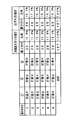
図30および図31は、この実施の形態において、演出制御基板80に搭載されているROMに格納されている選択肢振り分けテーブルの構成例を示す説明図である。図30および図31に示すように、選択肢振り分けテーブルには、最初に中央(打席)に表示する打者、右側に表示する打者および左側に表示する打者の組み合わせの選択率に関わるデータが設定されている。具体的には、157種類の数値(例えば0〜156)のうちの複数の数値が、各組合わせに応じて設定されている。各組合わせの間で重複する数値はない。そして、演出制御用CPU101は、0〜156の間を歩進する乱数カウンタから抽出した乱数値がと一致する数値を選択肢振り分けテーブルから検索し、一致した数値に対応した組み合わせを、可変表示装置9において最初に表示される各打者とする。
【0167】
選択肢振り分けテーブルには、確変大当りとする場合に使用されるテーブル、非確変大当りとする場合に使用されるテーブルおよびはずれとする場合に使用されるテーブルが、別個に設定されている。さらに、確変大当りとする場合には、遊技機への電源投入時から計数して初回、3回目および10回目に確変大当りが発生する場合に使用されるテーブル、2回目、5回目および8回目に確変大当りが発生する場合に使用されるテーブル、4回目、6回目、7回目および9回目と11回目以降に確変大当りが発生する場合に使用されるテーブルが使い分けられる。従って、この実施の形態では、演出制御用CPU101は、確変大当りの発生回数を計数し、発生回数に応じて図30に示す3つのうちのいずれかを使用する。すなわち、確変大当りの発生回数に応じて選択肢の振り分け方を異ならせる。
【0168】
図30に示すように、11回目以降では、打者Sを含む組み合わせが出現する比率が高められている。すなわち、大当りの発生回数が多いと打者Sを含む組み合わせが出現しやすい。その結果、打者Sを含む組み合わせが出現している遊技機は大当りが発生回数が多いことが遊技者に認識され、その遊技機で遊技を行っている遊技者の遊技意欲が高められるとともに、その遊技機への他の遊技者の参加意欲も高められる。このように、大当りの発生回数に応じて選択肢の振り分け方を異ならせることによって、遊技者の遊技機に対する興味をより引きつけることができる。なお、11回目よりも前でも、所定回目の大当り発生する場合には、打者Sが出現する比率が高め、遊技の興趣が低下しないような配慮がなされている。
【0169】
なお、この実施の形態では、確変大当りの発生回数に応じて選択肢の振り分け方を異ならせるが、非確変大当りについても発生回数に応じて選択肢の振り分け方を異ならせるようにしてもよい。また、確変/非確変に関わりなく、大当りの発生回数に応じて選択肢の振り分け方を異ならせるようにしてもよい。
【0170】
また、図31に示すように、この実施の形態では、非確変大当りとなる場合およびはずれとなる場合には、それぞれ、確変大当りとなる場合とは異なるテーブルが使用される。そして、確変大当りとなる場合には出現しうる打者の組み合わせのうちには、非確変大当りとなる場合およびはずれとなる場合には出現しないものがある。そして、非確変大当りとなる場合の打者の組み合わせの振り分け方とはずれとなる場合の振り分け方とは異なっている。その結果、遊技者は、打者の組み合わせによって、確変大当りとなるか、非確変大当りとなるか、はずれとなるかを予想することが可能になる。すなわち、表示される打者の組み合わせは、大当り予告機能を含んだものにもなっている。
【0171】
また、大当りの継続回数に応じて、打者の組み合わせの振り分け方を変えるようにしてもよい。その場合、例えば、図30に示された「初回、3回目、10回目」、「2回目、5回目、8回目」、「4回目、6回目、7回目、9回目、11回目以降」を、大当りの継続回数とする。演出制御用CPU101は、左中右の確定図柄の組み合わせが大当り図柄となった回数を計数するカウンタを備え、確定図柄の組み合わせが大当り図柄とならなかった場合にはカウンタのカウント値を0クリアする。そして、打者の組み合わせを決定する際に、カウンタのカウント値に応じて使用するテーブルを選択する。
【0172】
そのように構成した場合には、大当りの継続回数が11回目以降では、打者Sを含む組み合わせが出現する比率が高められる。すなわち、大当りの継続回数が多いと打者Sを含む組み合わせが出現しやすい。多数回大当りが継続しないと出願しない打者Sを出現させることによって、遊技者は大当りを多数回継続して享受している状態であることを打者Sの表示によって他の遊技者に対して視認させることができ、その遊技機で遊技を行っている遊技者の満足度がより高められる。
【0173】
演出制御手段は、第1の実施の形態の場合と同様に、選択演出の選択処理において、図30および図31に示された各テーブルのうちのいずれかを使用して選択肢としての打者の組み合わせを選定する。そして、第1の実施の形態の場合と同様に、図柄変動中処理において、遊技者に打者を選択させる演出を行うとともに、決定されている可変表示結果と選択された打者とに応じたプロセスデータを選択し、選択したプロセスデータの内容に従って選択演出を実行することができる。
【0174】
この実施の形態でも、演出制御手段が独自に演出態様を決定して実行しているので、選択演出が行われている間、遊技制御手段は、特に制御を行わなくてもよい。すなわち、選択演出によって遊技の興趣をより増進させるようにしても、遊技制御手段の負担が増えることはない。また、演出制御手段は、提示された選択肢に対して遊技者が選択を行わなかった場合には、あらかじめ決められている選択肢(例えば最初に打席入っているように表示された打者)を、選択された選択肢とみなして演出態様を決定して実行する。すなわち、演出制御手段は、提示された選択肢に対する遊技者の選択の有無によっても演出態様を独自に選択する制御を行っている。
【0175】
実施の形態3.
上記の各実施の形態では、複数の選択肢を遊技者に提示したが、1つの情報を遊技者に提示して、遊技者がその情報を選択するかしないかに応じて演出を異ならせるようにしてもよい。図32は、遊技者が情報を選択するかしないかを決定させるための画面例を示す説明図である。図32に示す例は、例えば、図22(C)に示す画面に代えて使用される。
【0176】
図32に示す例では、可変表示装置9に1種類の球種が表示される。そして、遊技者がタッチ部161bに指等を当ててその球種を選択することに決定した場合には、演出制御用CPU101は、図23(F)〜(I)に示すような演出を行う。大当りとすることに決定されている場合には、第1の実施の形態の場合と同様に、遊技者が選択した球種による投球がなされたかのような表示がなされるが((G)の左側参照)、大当りとしない(はずれとする)ことに決定されている場合には、遊技者が選択しない球種による投球がなされたかのような表示がなされる((G)の右側参照)。
【0177】
なお、この実施の形態では、1つのタッチ部が存在すればよい。すなわち、人体センサは1つ設けられていればよい。
【0178】
図33は、この実施の形態において、演出制御基板80に搭載されているROMに格納されている選択テーブルの構成例を示す説明図である。図33に示すように、選択テーブルには、表示する球種の選択率に関わるデータが設定されている。具体的には、157種類の数値(例えば0〜156)のうちの複数の数値が、球種に応じて設定されている。各球種の間で重複する数値はない。そして、演出制御用CPU101は、0〜156の間を歩進する乱数カウンタから抽出した乱数値がと一致する数値を選択テーブルから検索し、一致した数値に対応した球種を、可変表示装置9において表示される球種とする。
【0179】
選択テーブルには、確変大当りとする場合に使用されるテーブル、非確変大当りとする場合に使用されるテーブルおよびはずれとする場合に使用されるテーブルが、別個に設定されている(選択率A、選択率B、選択率C)。演出制御用CPU101は、図柄の可変表示の結果を確変大当りとするか、非確変大当りとするか、はずれとするかを確認し、確認結果に応じて、選択率A、選択率Bまたは選択率Cのテーブルを使用することに決定する。選択率A、選択率Bまたは選択率Cの各テーブルの間で、球種の選択率は異なっている。従って、遊技者は、表示された球種から、確変大当りとなるか、非確変大当りとなるか、はずれとなるかを予想することが可能になる。すなわち、表示される球種は、大当り予告機能を含んだものになっている。
【0180】
なお、この実施の形態でも、第2の実施の形態(実施の形態2)と同様に、確変大当りの発生回数に応じて球種の選択率を異ならせたり、非確変大当りの発生回数に応じて球種の選択率を異ならせるようにしてもよい。また、確変/非確変に関わりなく、大当りの発生回数に応じて球種の選択率を異ならせるようにしてもよい。
【0181】
そして、演出制御手段は、第1および第2の実施の形態の場合と同様に、選択演出の選択処理において、図33に示された各テーブルのうちのいずれかを使用して球種を選定する。そして、図柄変動中処理において、遊技者に球種を選択するか否か決定させる演出を行うとともに、決定されている可変表示結果と遊技者の決定結果とに応じたプロセスデータを選択し、選択したプロセスデータの内容に従って演出を実行することができる。
【0182】
以上のように、この実施の形態では、演出制御手段は、提示された選択肢(具体的には1つの情報)に対する遊技者の選択の有無によって演出態様を独自に選択する制御を行っている。
【0183】
実施の形態4.
上記の各実施の形態では、可変表示装置9における可変表示部150において画像によって選択肢を表示するようにしたが、選択肢を報知するための選択肢報知器を可変表示部150とは別に設けてもよい。図34は、ドットマトリクス型表示器の選択肢報知器163a,163bが設けられた例を示す説明図である。演出制御手段は、可変表示装置9における可変表示部150に選択肢を表示せず、選択肢報知器163a,163bに、選択肢を示す情報を表示するが、その他の制御は第1〜第3の実施の形態の制御と同様である。
【0184】
また、選択肢報知器163a,163bとして、遊技者に選択肢を報知できるものであれば、ドットマトリクス型表示器だけでなく、7セグメントLEDや、複数のランプまたはLEDのうちの選択肢に対応したランプまたはLEDのみを表示する表示装置(選択ランプまたは選択LEDのみを点灯させる表示装置)など、他の表示器または表示装置を使用することができる。
【0185】
以上のように、上記の各実施の形態では、図35に示すように、遊技の進行を制御する遊技制御手段31Aと、遊技制御手段からのコマンドにもとづいて識別情報の可変表示に関わる演出を実行する複数種類の演出手段(可変表示装置9、ランプ・LED、スピーカ27)を制御する演出制御手段101Aと、遊技者が選択入力を入力するための選択手段161とを備え、演出制御手段101Aが、遊技制御手段31Aから受信したコマンドにもとづいて遊技者に複数の選択肢A,B,Cを提示する選択肢提示手段101aと、選択手段161に入力された選択入力がいずれの選択肢に対応する選択入力であったのかにもとづいて、複数種類の演出手段を用いて実行する演出態様を独自に決定する演出決定手段101bとを含んでいる。
【0186】
そのような構成によれば、選択演出によって遊技者は自身の選択に応じて遊技演出が変化したように感ずることができ、遊技者に新たな興趣を与えることができる。ただし、大当りとするか否かは遊技機における遊技制御手段が決定しているのであって、実際には、遊技者の選択によって大当りとするか否かが決定されているわけではない。そして、選択演出を実現する際に、遊技制御手段は特に新たな制御を行うわけではなく、遊技制御手段の負担は増大しない。また、1つの演出制御手段が、可変表示装置9の表示制御、演出用のランプ・LEDの点滅制御およびスピーカ27からの音出力制御を行っているので、演出用の各電気部品の間の同期をとることは容易である。また、選択演出を実行する場合に、ハードウェア的には、遊技盤に人体センサを設けるだけでよく、他の部品追加を必要としない。
【0187】
なお、上記の実施の形態では、選択演出として野球を例にしたが、野球は単なる一例であって、他のゲーム性のあるものを使用してもよい。
【0188】
また、上記の各実施の形態では、発光体制御に関して演出用CPU101とバス接続されるランプドライバ基板35を設け、音制御に関してデータROMが搭載されている音声出力基板70に対して演出用CPU101からデータ(音番号データ)を出力するように構成したが、双方を同様の構成にしてもよい。すなわち、発光体制御に関しても音制御に関しても演出用CPU101とバス接続されるそれぞれのドライバ基板を設けたり、発光体制御に関しても音制御に関してもそれぞれの基板にデータROMを搭載して演出用CPU101からデータ(制御データ番号を指定するデータ)を出力するように構成してもよい。
【0189】
なお、上記の各実施の形態のパチンコ遊技機1は、始動入賞にもとづいて可変表示装置9に可変表示される特別図柄の停止図柄が所定の図柄の組み合わせになると所定の遊技価値が遊技者に付与可能になる第1種パチンコ遊技機であり、かつ、プリペイドカードによって球貸しを行うカードリーダ(CR:Card Reader )式の第1種パチンコ遊技機であったが、プリペイドカードによって球貸しを行うCR式パチンコ遊技機だけでなく、現金によって球貸しを行うパチンコ遊技機にも適用可能である。さらに、始動入賞にもとづいて開放する電動役物の所定領域への入賞があると所定の遊技価値が遊技者に付与可能になる第2種パチンコ遊技機や、始動入賞にもとづいて可変表示される図柄の停止図柄が所定の図柄の組み合わせになると開放する所定の電動役物への入賞があると所定の権利が発生または継続する第3種パチンコ遊技機であっても、本発明を適用できる。
【0190】
また、上述した実施の形態において、「特別遊技状態」とは、大当りとなりやすい遊技者にとって有利な状態を意味する。具体的には、「特別遊技状態」は、例えば、特別図柄が大当り図柄で揃う確率が高確率状態とされる確変状態、単位時間あたりの普通図柄の変動回数が高められる時短状態、可変入賞球装置15の開成期間や開成回数が高められる開放延長状態などの大当りとなる確率が高められている高確率状態である。なお、時短状態は、可変入賞球装置15の開放回数が高められていることから単位時間あたりの入賞回数が増加し、単位時間あたりの特別図柄の可変表示回数が高められるので、大当りとなる確率が高められている状態といえる。また、同様に、開放延長状態は、可変入賞球装置15の開成期間や開成回数が高められていることから単位時間あたりの入賞回数が増加し、単位時間あたりの特別図柄の可変表示回数が高められるので、大当りとなる確率が高められている状態といえる。
【0191】
【発明の効果】
以上のように、請求項1記載の発明では、複数種類の演出手段を制御する演出制御手段が、可変表示パターンコマンドを受信したことにもとづいて、識別情報の可変表示を実行し、可変表示パターンコマンドで特定される可変表示パターンに対応した可変表示時間が経過したときに、識別情報の可変表示の表示結果を導出表示する可変表示実行手段と、可変表示パターンコマンドのうち特定の可変表示パターンを特定可能な可変表示パターンコマンドを受信したことにもとづいて、遊技者に複数の選択肢を提示する選択肢提示手段と、遊技制御手段を介することなく、選択手段からの操作信号を該選択手段から直接入力する操作信号入力手段と、選択手段からの操作信号を入力したことにもとづいて、選択手段による選択操作の入力がいずれの選択肢に対応するかを判定する選択肢判定手段と、事前決定手段の決定結果と選択肢判定手段の判定結果とにもとづいて複数種類の演出手段を用いて実行する演出態様を独自に決定する演出決定手段とを含み、演出制御手段が特定の可変表示パターンを特定可能な可変表示パターンコマンドを受信したときに、選択肢判定手段が、選択手段の操作の有効期間として特定の可変表示パターンに対応した可変表示時間に含まれる固定期間を設定し、該有効期間内における選択操作の入力がいずれの選択肢に対応するかを判定し、可変表示実行手段が、選択手段からの選択入力のタイミングにかかわらず、選択肢判定手段により判定された選択肢に対応する表示態様による可変表示を有効期間の経過後において実行するように構成されているので、遊技制御手段の負担を増すことなく演出内容をより豊富にして遊技の興趣をより増進させることができる。
【0193】
請求項2記載の発明では、演出制御手段が、有効期間を報知する制御を行うように構成されているので、遊技者は選択手段の操作の有効期間を容易に認識することができる。
【0194】
請求項3記載の発明では、選択肢選択手段が、事前決定手段によって特定遊技状態に制御すると決定されているか否かに応じて異なる割合で各選択肢の組み合わせを選択するように構成されているので、遊技者は提示された選択肢によって所定の表示結果の出現を予測することが可能になる。
【0195】
請求項5記載の発明では、選択肢選択手段が、特定の表示結果の表示回数に応じて特定の選択肢の組み合わせを異なる割合で選択するように構成されているので、遊技者に提示される選択肢によって遊技者の満足度を上げるような演出を行うことができる。
【0196】
請求項6記載の発明では、演出制御手段が、ROMに記憶されているデータにもとづいて演出手段を制御し、複数の演出手段の制御に関わるデータのうち少なくとも一部のデータを同一ROMに格納したので、部品点数を節減することができる。
【0197】
請求項7記載の発明では、演出制御手段を搭載した演出制御基板と、演出制御基板から出力される信号にもとづいて、演出手段を動作させるための動作信号を生成するドライバ基板とを別個に備えた構成であるから、双方の基板のうちドライバ基板のみを交換するだけで機種変更を行うことが可能になる。
【0198】
請求項8記載の発明では、演出制御手段は演出制御用CPUを含み、ドライバ基板に、演出制御用CPUとバス接続され、選択手段からの選択入力を取り込むための入力ポートを搭載したので、演出制御基板の汎用性をより高めることができる。
【0199】
請求項9記載の発明では、ドライバ基板には、演出手段としての音出力手段から出力される音を生成するためのデータを記憶した音データROMと、演出制御手段から出力される音指定データにもとづいて音データROMに記憶されているデータを選択し、選択したデータにもとづいて音出力手段を制御する音声合成用ICを搭載したので、演出制御基板に搭載された演出制御手段の負担を軽減することができる。
【図面の簡単な説明】
【図1】 パチンコ遊技機を正面からみた正面図である。
【図2】 ガラス扉枠を取り外した状態での遊技盤の前面を示す正面図である。
【図3】 遊技制御基板(主基板)の回路構成例を示すブロック図である。
【図4】 演出制御基板、ランプドライバ基板および音声出力基板の回路構成例を示すブロック図である。
【図5】 人体センサの作用を説明するための説明図である。
【図6】 主基板におけるCPUが実行するメイン処理を示すフローチャートである。
【図7】 2msタイマ割込処理を示すフローチャートである。
【図8】 各乱数を示す説明図である。
【図9】 特別図柄プロセス処理を示すフローチャートである
【図10】 変動パターンの一例を示す説明図である。
【図11】 変動パターンの振り分け方を示す説明図である。
【図12】 始動口スイッチ通過処理を示すフローチャートである。
【図13】 特別図柄通常処理を示すフローチャートである。
【図14】 特別図柄停止図柄設定処理を示すフローチャートである。
【図15】 演出制御コマンドの信号線を示す説明図である。
【図16】 制御コマンドを構成する8ビットの制御信号とINT信号との関係を示すタイミング図である。
【図17】 演出制御コマンドの内容の一例を示す説明図である。
【図18】 演出制御用CPUが実行するメイン処理を示すフローチャートである。
【図19】 コマンド受信バッファの構成を示す説明図である。
【図20】 演出制御プロセス処理を示すフローチャートである。
【図21】 プロセスデータの一構成例を示す説明図である。
【図22】 選択演出の一例を示す説明図である。
【図23】 選択演出の一例を示す説明図である。
【図24】 選択肢振り分けテーブルの構成例を示す説明図である。
【図25】 選択演出の選択処理を示すフローチャートである。
【図26】 全図柄変動開始処理を示すフローチャートである。
【図27】 図柄変動中処理を示すフローチャートである。
【図28】 図柄変動中処理を示すフローチャートである。
【図29】 3つの選択肢を提示しいずれか1つの選択肢を選択させる画面例を示す説明図である。
【図30】 選択肢振り分けテーブルの構成例を示す説明図である。
【図31】 選択肢振り分けテーブルの構成例を示す説明図である。
【図32】 遊技者が情報を選択するかしないかを決定させるための画面例を示す説明図である。
【図33】 選択テーブルの構成例を示す説明図である。
【図34】 選択肢報知器が設けられた例を示す説明図である。
【図35】 本発明の概要を示す概念図である。
【符号の説明】
1 パチンコ遊技機
9 可変表示装置
17a,17b 発光部(人体センサ)
19a,19b 受光部(人体センサ)
31 主基板
31A 遊技制御手段
35 ランプドライバ基板
56 CPU
70 音声出力基板
80 演出制御基板
101 演出制御用CPU
101A 演出制御手段
101a 選択肢提示手段
101b 演出決定手段
150 可変表示部
161 選択手段
163a,163b 選択肢報知器[0001]
BACKGROUND OF THE INVENTION
The present invention has a variable display means whose display state can be changed, and a game such as a pachinko machine that can be controlled to a specific game state advantageous to the player when the display result in the variable display means is in a specific display mode. Related to the machine.
[0002]
[Prior art]
As a gaming machine, a game medium such as a game ball is launched into a game area by a launching device, and when a game medium wins a prize area such as a prize opening provided in the game area, a predetermined number of prize balls are paid out to the player. There is something to be done. Furthermore, variable display means capable of variably displaying the identification information is provided, so that when the display result of the variable display of the identification information becomes a specific display result, it can be controlled to a specific gaming state advantageous to the player. There is something configured.
[0003]
The specific game state means a state advantageous for a player who is given a predetermined game value. Specifically, for example, the right for a game state that is advantageous for a player who is easy to win a hit (a big hit gaming state) or a player's advantageous state occurs, for example, in a specific game state A state in which a predetermined game value is given, such as a state in which a condition for paying out a prize game medium is easily established.
[0004]
In a pachinko gaming machine, the fact that the display result of the variable display means for displaying a special symbol (identification information) is a combination of specific display modes determined in advance is usually called “big hit”. When a big hit occurs, for example, the big winning opening is opened a predetermined number of times, and the game shifts to a big hit gaming state in which a hit ball is easy to win. And in each open period, if there is a prize for a predetermined number (for example, 10) of the big prize opening, the big prize opening is closed. And the number of times of opening the special winning opening is fixed to a predetermined number (for example, 15 rounds). An opening time (for example, 29.5 seconds) is determined for each opening, and even if the number of winnings does not reach a predetermined number, the big winning opening is closed when the opening time elapses. Further, when a predetermined condition (for example, winning in the V zone provided in the big prize opening) is not established at the time when the big prize opening is closed, the big hit gaming state is ended.
[0005]
In addition, the symbols other than the symbol that becomes the final stop symbol (for example, the middle symbol of the left and right middle symbols) on the variable display means continue for a predetermined time and stop, swing, or expand in a state that matches the specific display result. The possibility of big hits continues before the final result is displayed due to a reduced or deformed state, or multiple symbols changing synchronously with the same symbol, or the position of the display symbol changing. An effect performed in a state in which the player is in a state (hereinafter, these states are referred to as reach states) is referred to as reach effect. Further, the reach state and its state are referred to as a reach mode. Furthermore, variable display including reach production is called reach variable display. In the reach state, the interest of the game is enhanced by making the variation pattern different from the variation pattern in the normal state. And when the display result of the symbol variably displayed on the variable display means does not satisfy the condition for reaching the reach state, it becomes “displaced”, and the variable display state ends. A player plays a game while enjoying how to generate a big hit.
[0006]
The gaming machine is provided with a control board on which various control means are mounted in addition to a game control board on which game control means for controlling the overall progress of the game is mounted. Then, the game control means transmits a control command indicating a control instruction for the electrical component to each control means mounted on each control board in accordance with the game situation. As each control means, for example, a display control means for controlling a variable display device as an electrical component, a lamp control means for controlling a light emitter (lamp or LED) for effect control as an electrical component, a speaker as an electrical component There is a sound control means for controlling the sound generation from.
[0007]
[Problems to be solved by the invention]
If the game control means is configured to transmit control commands to a large number of control means, the burden on the game control means becomes excessive. Therefore, each control means that receives a control command from the game control means may be configured to execute the effect by uniquely determining the content of the effect. However, in such a configuration, each control means must synchronize effects with other control means, and the burden on each control means becomes excessive..
[0009]
Accordingly, an object of the present invention is to provide a gaming machine capable of further enhancing the fun of the game by making the contents of production more abundant without increasing the burden on the game control means and other control means.
[0010]
[Means for Solving the Problems]
The gaming machine according to the present invention has a variable display unit (for example, a variable display device 9) capable of variably displaying a plurality of types of identification information.TheIt is possible to control to a specific gaming state (for example, jackpot gaming state) that is advantageous for the player when the display result of the identification information on the variable display section becomes a specific display result (for example, a jackpot symbol with the left, middle and right symbols aligned) A game control means (for example, CPU 56) for controlling the progress of the game and an effect related to variable display of identification information based on a command (for example, an effect control command) from the game control means. An effect control means (for example, an effect control CPU 101) for controlling a plurality of types of effect means (for example,
[0012]
The effect control means may be configured to perform control for notifying the effective period (for example, execute the processes of steps S834 and S836).
[0013]
From combinations of multiple types of optionsOptions presented by the option presentation meansCombinationOption selection means (for example, a portion of the production control means for executing steps S661 to S667), and the option selection means includes:Depending on whether or not it has been decided to control to a specific gaming state by means of prior decisionAt a different rateEach option combinationIt may be configured to select (for example, use an option distribution table shown in FIG. 24).
The pre-determining means determines whether to control to a special gaming state that tends to give a specific display result after ending the specific gaming state when it is determined to control to a specific gaming state. The selection means may be configured to be able to select a combination of special options among a plurality of combinations of options only when it is determined by the pre-decision means to control to the special gaming state.
[0014]
From combinations of multiple types of optionsOptions presented by the option presentation meansCombinationOption selection means for selecting a specific option (for example, each of the combinations of batters shown in FIG. 30) according to the number of display times of a specific display result (for example, jackpot symbol).CombinationMay be selected at different ratios (for example, the option distribution table shown in FIG. 30 is used according to the number of consecutive big hits).
[0015]
The effect control means may control the effect means based on data (for example, a program) stored in the ROM, and store at least a part of the data related to the control of the plurality of effect means in the same ROM. .
[0016]
An effect control board (for example, effect control board 80) equipped with effect control means and a driver board (for example, lamp driver board 35) that generates an operation signal for operating the effect means based on a signal output from the effect control board. And a sound output board 70) may be separately provided.
[0017]
The effect control means includes an effect control CPU, and is connected to a driver board (for example, the lamp driver board 35) by a bus for effect control and takes in a selection input from the selection means (for example, detection signals of the light receiving
[0018]
The driver board includes a sound data ROM (for example, audio data ROM 704) that stores data for generating sound output from sound output means (for example, the speaker 27) as effect means, and sound output from the effect control means. A voice synthesizing IC that selects data stored in the sound data ROM based on the designated data (for example, sound number data) and controls the sound output means based on the selected data may be mounted.
[0019]
DETAILED DESCRIPTION OF THE INVENTION
Hereinafter, an embodiment of the present invention will be described with reference to the drawings. First, the overall configuration of a first type pachinko gaming machine that is an example of a gaming machine will be described. FIG. 1 is a front view of a pachinko gaming machine as viewed from the front, and FIG. 2 is a front view showing the front of the game board.
[0020]
The
[0021]
As shown in FIG. 1, the
[0022]
Near the center of the
[0023]
In addition, since the symbol display area and the start
[0024]
Below the
[0025]
An open /
[0026]
When a game ball wins the
[0027]
In this embodiment, the left and right lamps (the symbols can be visually recognized at the time of lighting) are alternately turned on, whereby the normal symbols are variably displayed, and the variable display continues for a predetermined time (for example, 29.2 seconds). If the left lamp is turned on at the end of the variable display, it is a win. Whether or not to win is determined by whether or not the value of the random number extracted when the game ball wins the
[0028]
Furthermore, in the probability variation state as the special game state, the probability that the stop symbol in the
[0029]
The
[0030]
In this example, a
[0031]
The
[0032]
The game balls launched from the hit ball launching device enter the
[0033]
The variable display of the special symbol on the
[0034]
When the combination of the special symbols in the
[0035]
Furthermore, in this embodiment, as shown in FIG. 2,
[0036]
FIG. 3 is a block diagram illustrating an example of a circuit configuration in the
[0037]
Although not shown in FIG. 3, the count switch short circuit signal is also transmitted to the
[0038]
Further, according to the data given from the
[0039]
The
[0040]
Further, a part or all of the RAM (may be a CPU built-in RAM) 55 is a backup RAM backed up by a backup power source created on the power supply board. That is, even if the power supply to the gaming machine is stopped, a part or all of the contents of the
[0041]
In this embodiment, the effect control means mounted on the
[0042]
A drive signal for driving the lamp / LED is generated in the
[0043]
Further, the display control of the
[0044]
Furthermore, the effect control means mounted on the
[0045]
FIG. 4 is a block diagram illustrating a circuit configuration example of the
[0046]
Further, the
[0047]
In the
[0048]
Further, a drive signal for causing the
[0049]
In this embodiment, the lamps / LEDs, the human body sensors, and the effect driving means provided in the gaming machine are controlled by the effect control means including the
[0050]
The
[0051]
In the
[0052]
The data corresponding to the sound number data stored in the
[0053]
In this embodiment, the sound and sound output from the
[0054]
Also, an
[0055]
FIG. 5 is an explanatory diagram for explaining the operation of the human body sensor as the selection means for the player to input the selection input. Light from the
[0056]
As will be described later, the
[0057]
The human body sensor having the structure shown in FIG. 5 is an example, and any human body sensor having any structure can be used as long as it can detect that a player's finger or the like is applied to the
[0058]
Next, the operation of the gaming machine will be described. FIG. 6 is a flowchart showing main processing executed by game control means (
[0059]
In the initial setting process, the
[0060]
The
[0061]
The
[0062]
Interrupt mode 0: The built-in device that has issued the interrupt request sends an RST instruction (1 byte) or a CALL instruction (3 bytes) onto the internal data bus of the CPU. Therefore, the
[0063]
Interrupt mode 1: In this mode, when an interrupt is accepted, the mode always jumps to address 0038 (h).
[0064]
Interrupt mode 2: A mode in which the address synthesized from the value (1 byte) of the specific register (I register) of the
[0065]
Therefore, when the interrupt
[0066]
Next, the
[0067]
If the
[0068]
After confirming that there is a backup, the
[0069]
If the check result is normal, the
[0070]
In this embodiment, it is confirmed whether or not the data in the backup RAM area is stored by using both the backup flag and the check data, but only one of them may be used. That is, either the backup flag or the check data may be used as an opportunity for executing the state recovery process.
[0071]
In the initialization process, the
[0072]
Then, a CTC register set in the
[0073]
When the execution of the initialization process (steps S11 to S14) is completed, the display random number update process (step S17) and the initial value random number update process (step S18) are repeatedly executed in the main process. When the display random number update process and the initial value random number update process are executed, the interrupt disabled state is set (step S16). When the display random number update process and the initial value random number update process are finished, the interrupt enabled state is set. (Step S19). The display random number is a random number for determining a symbol displayed on the
[0074]
Note that when the display random number update process is executed, the interrupt is prohibited. The display random number update process is also executed in the timer interrupt process described later, and thus conflicts with the process in the timer interrupt process. This is to avoid that. That is, if a timer interrupt is generated during the process of step S17 and the counter value for generating the display random number is updated during the timer interrupt process, the continuity of the count value is impaired. There is a case. However, such an inconvenience does not occur if the interrupt is prohibited during the process of step S17.
[0075]
When the timer interrupt occurs, the
[0076]
Next, a process of updating the count value of each counter for generating each determination random number such as a big hit determination random number used for game control is performed (step S22). The
[0077]
FIG. 8 is an explanatory diagram showing each random number. It is explanatory drawing which shows each random number. Each random number is used as follows.
(1) Random 1: Decide whether or not to generate a big hit (for big hit judgment)
(2) Random 2-1 to 2-3 (Random 2): For determining the left middle right of the special symbol (special symbol left middle right)
(3) Random 3: Determines the combination of special symbols that generate a big hit (for determining big hit symbols)
(4) Random 4: Determine the variation pattern of the special symbol (for variation pattern determination)
(5) Random 5: Decide whether or not to reach when no big hit is generated (for reach determination)
(6) Random 6: Determines whether or not to generate a hit based on a normal symbol (for normal symbol hit determination)
(7) Random 7: Determine initial value of random 1 (for determining random 1 initial value)
(8) Random 8: Determine initial value of random 6 (for determining random 6 initial value)
[0078]
In step S22 in the game control process shown in FIG. 7, the
[0079]
In this embodiment, when the left, middle and right symbols stop together, that is, when the left, middle, and right symbols match, a big hit is obtained. It becomes. In the case of a big hit, if the left middle right symbol is an odd symbol, the state shifts to a probability variation state (high probability state).
[0080]
Further, the
[0081]
Next, the
[0082]
Further, the
[0083]
In addition, the
[0084]
And CPU56 performs the memory | storage process which checks the increase / decrease in the number-of-start-winning memory | storage number (step S31). In addition, a test terminal process, which is a process for outputting a test signal for enabling the control state of the gaming machine to be confirmed outside the gaming machine, is executed (step S32). Further, when a predetermined condition is established, a drive command is issued to the solenoid circuit 59 (step S33). The
[0085]
With the above control, in this embodiment, the game control process is started every 2 ms. In this embodiment, the game control process is executed by the timer interrupt process. However, in the timer interrupt process, for example, only a flag indicating that an interrupt has occurred is set, and the game control process is performed by the main process. May be executed.
[0086]
FIG. 9 is a flowchart showing an example of a special symbol process processing program executed by the
[0087]
Special symbol normal processing (step S300): Waits until the variable symbol variable display can be started. When the special symbol variable display can be started, the start winning memory number is confirmed. If the start winning memorization number is not 0, it is determined whether or not to win the game as a result of variable display of special symbols. Then, the internal state (special symbol process flag) is updated so as to shift to step S301.
[0088]
Special symbol stop symbol setting process (step S301): The stop symbol of the left middle right symbol after variable display of the special symbol is determined. Then, the internal state (special symbol process flag) is updated so as to shift to step S302.
[0089]
Fluctuation pattern setting process (step S302): A variation pattern (variable display mode) of variable display of special symbols is determined according to a random 4 value. Also, a variable time timer is started. At this time, the left middle right final stop symbol and information for instructing the variation mode (variation pattern) are transmitted to the
[0090]
Special symbol variation process (step S303): When a predetermined time (the time indicated by the variation time timer in step S302) elapses, the internal state (special symbol process flag) is updated to shift to step S304.
[0091]
Special symbol stop process (step S304): Control is performed so that all symbols displayed on the
[0092]
Big winning opening opening process (step S305): Control for opening the big winning opening is started. Specifically, the counter and the flag are initialized, and the
[0093]
Processing during opening of a special winning opening (step S306): processing for sending an effect control command for displaying a large winning opening round to the
[0094]
Specific area valid time process (step S307): The presence / absence of passing through the
[0095]
Big hit end processing (step S308): Control for causing the effect control means to perform display control for notifying the player that the big hit gaming state has ended. Then, the internal state is updated so as to shift to step S300.
[0096]
FIG. 10 is an explanatory diagram showing an example of a variation pattern used in this embodiment. In FIG. 10, “EXT” indicates the second byte of EXT data in the effect control command having a two-byte configuration (MODE data and EXT data). In this embodiment, the “MODE” data in the first byte is “80 (H)” in all cases. “Time” indicates the variation time of the special symbol (variable display period of identification information). As shown in FIG. 10, during a high probability (during probability variation), the variation time of each variation pattern is shortened by 3.5 seconds.
[0097]
The “normal fluctuation” is a fluctuation pattern that does not involve a reach mode. “Normal” is a variation pattern that involves a reach mode, but the variation result (stop symbol) does not cause a big hit. “Reach A” is a variation pattern having a reach mode different from “Normal”. Different reach modes mean that different modes of change (speed, direction of rotation, etc.), characters, etc. appear in the period during which the reach effect is being performed. For example, in “normal”, the reach mode is realized by only one type of change mode, whereas in “reach A”, a reach mode including a plurality of change modes with different speeds and directions of change is realized.
[0098]
“Reach B” is a fluctuation pattern having a reach mode different from “normal” and “reach A”. “Reach C” is a variation pattern having a reach form different from “Normal”, “Reach A”, and “Reach B”. “Reach D” is a variation pattern having a reach form different from “Normal”, “Reach A”, “Reach B”, and “Reach C”. The “full rotation” is a variation pattern including a reach mode in which the left and right middle symbols vary together.
[0099]
“With selection effect” is a variation pattern with a selection effect described later. “Hit” indicates that a big hit occurs after the end of the change of the symbol. “Re” indicates that a re-variation mode after a so-called temporary stop appears. “Return” indicates that the stop symbol includes a change mode in which the stop symbol is reversely changed after the stop position is temporarily stopped.
[0100]
In this embodiment, a shortened display pattern is further used. The shortened display pattern is a very short variation pattern in which the variation time of the left middle right symbol is 1.0 seconds, for example.
[0101]
FIG. 11 is an explanatory diagram showing how the variation pattern is distributed by the game control means of the
[0102]
FIG. 12 is a flowchart showing the start port switch passing process (step S312). In the start port switch passing process, the
[0103]
FIG. 13 is a flowchart showing the special symbol normal process (step S300) in the special symbol process. In the special symbol normal process, the
[0104]
If the starting winning memory number is not 0, each random number value stored in the storage area corresponding to the starting winning memory number = 1 is read and stored in the random number buffer area of the RAM 55 (step S53), and the starting winning
[0105]
Next, the
[0106]
FIG. 14 is a flowchart showing a special symbol stop symbol setting process (step S301) in the special symbol process. In the special symbol stop symbol setting process, the
[0107]
If the big hit flag is not set, the
[0108]
If it is decided not to reach in step S66, a stop symbol in the case of a loss is determined (step S68). Specifically, the left symbol is determined according to the value read in step S53, that is, the extracted random 2-1 value, the middle symbol is determined according to the random 2-2 value, and the random 2-3 value is determined. The right design is determined according to. Here, when the left and right symbols match, the right symbol is shifted by one symbol so that it does not become reach. Then, the process proceeds to step S63. When the probability variation symbol is determined in step S62, a probability variation flag indicating that the game is shifted to the probability variation state after the big hit game is ended is set.
[0109]
Next, a method for sending a control command from the game control means to the effect control means will be described. FIG. 15 is an explanatory diagram showing a signal line of an effect control command transmitted from the
[0110]
In this embodiment, the effect control command has a 2-byte structure, the first byte represents MODE (command classification), and the second byte represents EXT (command type). The first bit (bit 7) of the MODE data is always “1”, and the first bit (bit 7) of the EXT data is always “0”. Note that such a command form is an example, and other command forms may be used. For example, a control command composed of 1 byte or 3 bytes or more may be used.
[0111]
As shown in FIG. 16, the 8-bit effect control command data of the effect control command is output in synchronization with the effect control INT signal. The effect control means mounted on the
[0112]
The production control command is sent only once so that the production control means can recognize it. In this example, “recognizable” means that the level of the production control INT signal changes, and that it is sent only once so as to be recognizable means that, for example, the first byte and the second byte of the production control command data respectively. Accordingly, the production control INT signal is output in a pulse shape (rectangular wave shape) only once. The effect control INT signal may have a polarity opposite to that shown in FIG.
[0113]
FIG. 17 is an explanatory diagram showing an example of the contents of the effect control command sent to the
[0114]
The command 88XX (H) (X = any value of 4 bits) is an effect control command relating to a variation pattern of a normal symbol variably displayed on the
[0115]
Commands 91XX (H), 92XX (H), and 93XX (H) are effect control commands for designating a left middle right stop symbol of a special symbol. A symbol number is set in “XX”. Command A000 (H) is an effect control command for instructing stop of variable symbol special display. The command BXXX (H) is an effect control command that is sent from the start of the big hit game to the end of the big hit game. The commands C000 (H) to EXXXX (H) are effect control commands relating to the display state of the
[0116]
The command E0XX (H) is an effect control command indicating the number of start
[0117]
The command E400 (H) is a command transmitted when the high probability state is changed to the low probability state, and the command E401 (H) is transmitted when the low probability state is changed to the high probability state. It is a command.
[0118]
When the effect control means of the
[0119]
The variable display start designation command indicating the start of variable display and the variable display mode designation command capable of specifying the variable display mode are realized by the variation pattern designation effect control command, and the identification information designation command capable of identifying the display result of the identification information. Is realized by an effect control command for designating the left symbol, middle symbol, and right symbol, and a variable display end designating command indicating the end of variable display is realized by an effect control command for stopping the special symbol. In this embodiment, the production control command for specifying the variation pattern is also used as the variable display start specifying command for indicating the start of variable display and the variable display mode specifying command for specifying the variable display mode. The designation command and the variable display mode designation command that can specify the variable display mode may be separated.
[0120]
Next, the operation of the effect control means will be described. FIG. 18 is a flowchart showing main processing executed by the
[0121]
In this embodiment, the timer interrupt takes every 2 ms. That is, the effect control process is activated every 2 ms. In this embodiment, only the flag is set in the timer interrupt process, and the specific effect control process is executed in the main process, but the effect control process may be executed in the timer interrupt process.
[0122]
In the effect control process, the
[0123]
Next, an effect control command reception process from the
[0124]
An INT signal for effect control from the
[0125]
FIG. 20 is a flowchart showing the effect control process (step S705) in the main process shown in FIG. In the effect control process, any one of steps S800 to S806 is performed according to the value of the effect control process flag. In each process, the following process is executed.
[0126]
Fluctuation pattern command reception waiting process (step S800): It is confirmed whether or not an effect control command (variation pattern command) capable of specifying the fluctuation time is received by the command reception interrupt process. Specifically, it is confirmed whether or not a flag (variation pattern reception flag) indicating that a variation pattern command has been received is set. The variation pattern reception flag is set when it is confirmed by command analysis processing that a variation pattern designation effect control command has been received (step S623).
[0127]
Selection effect selection processing (step S801): In the selection effect, it is determined which mode of initial display is to be performed.
[0128]
All symbol variation start processing (step S802): Control is performed so that variation of the left middle right symbol is started.
[0129]
Symbol variation processing (step S803): Controls the switching timing of each variation state (variation speed) constituting the variation pattern, and monitors the end of the variation time. In addition, stop control of the left and right symbols is performed. Furthermore, when performing the selection effect, the display mode of the selection effect is also controlled.
[0130]
All symbol stop waiting setting process (step S804): If an effect control command (special symbol stop effect control command) for instructing stop of all symbols is received at the end of the variation time, the symbol variation is stopped and the stop symbol ( Control to display the fixed symbol).
[0131]
Big hit display process (step S805): After the end of the fluctuation time, the control of the probability variable big hit display or the normal big hit display is performed.
[0132]
Process during jackpot game (step S806): Control during jackpot game is performed. For example, when an effect control command for display before opening the big winning opening or display when opening the big winning opening is received, display control of the number of rounds is performed.
[0133]
FIG. 21 is an explanatory diagram showing a configuration example of process data set for each variation pattern table. The process data is composed of data obtained by collecting a plurality of combinations of process timer set values and presentation control execution data. The effect control execution data includes display control execution data and lamp control execution data. As the display control execution data, data indicating the display state of the
[0134]
Thus, the effect control means controls the effect means based on the program and process data stored in the ROM, and controls a plurality of effect means (in this embodiment, the
[0135]
The process data shown in FIG. 21 is stored in the ROM of the
[0136]
22 and 23 are explanatory diagrams showing examples of selection effects. The selection effect is executed in a period during which the reach effect is performed. In addition, the selection effect is selected by allowing the player to select one option from a plurality of options presented to the player by the effect control means or to determine whether to select information to be presented to the player. This is an effect that is executed using all or a part of the
[0137]
In the example shown in FIG. 22 and FIG. 23, after the middle left and right symbols change to reach (see (A) and (B)), two types of spheres (for example, curve and tornado) are variable display devices. 9 (see (C)). At that time, the symbol display area moves to the upper right in the
[0138]
In this embodiment, the selection effective
[0139]
For example, when the selection valid period ends, an effect corresponding to the player's selection is started. As shown in FIG. 23 (F), the display is such that the pitcher throws a ball. If it is decided to win after reaching the reach effect, a display is made as if the player has thrown the ball type selected (see the left side of (G)). In addition, when it is decided not to make a big hit after the reach performance (deemed to be out of place), a display is made as if a pitch was made by the player who did not select the ball type ((G) See right). Further, if it is determined to be a big hit, a display is made as if the batter hit the ball and made a home run (see the left side of (H)). If it is determined that the batter is to be disengaged, a display as if the batter has swung is displayed (see the right side of (H)).
[0140]
Then, when it is determined to be a big hit at the end of the symbol variation period, the symbol matching the left and right symbols is stopped and displayed as the middle symbol. If it is determined to be off, a symbol different from the left and right symbols is stopped and displayed as the middle symbol (see (I)).
[0141]
While the display effects between (C) to (H) of FIGS. 22 and 23 are being performed, effects that are synchronized with the display effects are performed by the lamps / LEDs for the effects and the
[0142]
Further, the player can feel as if the game effect has changed according to his / her selection, and can give the player a new interest. However, whether or not to win is determined by the game control means in the gaming machine, and actually whether or not to win is determined by the player's selection. That is, if it is determined that the game is a big hit, no matter which option is selected by the player (in this example, a curve or a tornado), the ball type selected by the player at the stage shown in FIG. In the stage shown in FIG. 23 (H), a display is made as if the batter hit a home run. In addition, if it is determined to be out of play, no matter which option the player selects, the ball type that the player did not select is displayed at the stage shown in FIG. At the stage shown in FIG. 23 (H), a display is made as if the batter has struck. If it is determined that the player is not selected, the player does not display the ball type that is not selected by the player, but the ball type is completely different (for example, the curve of the curve and the tornado by the player). (Shoot or straight) when selected is also displayed.
[0143]
The ball type is selected by the player placing a finger or the like on the
[0144]
Next, the control of the selection effect by the effect control means will be described. The ROM mounted on the
[0145]
As shown in FIG. 24, data relating to the selection rate of the combination of the sphere type displayed on the left side and the sphere type displayed on the right side is set in the option sorting table. Specifically, a plurality of numerical values among 191 types of numerical values (for example, 0 to 190) are set according to each combination. There are no duplicate numbers between each combination. Then, the
[0146]
In the option distribution table, a table used for the probability variation jackpot, a table used for the non-probability variation jackpot, and a table used for the deviation are set separately (selection rate A , Selectivity B, selectivity C). The
[0147]
The
[0148]
FIG. 25 is a flowchart showing a selection effect selection process (step S801). In the selection effect selection process, the
[0149]
Next, the count value of the random number counter is read out to be a random number value (step S666), and a combination of left and right sphere types corresponding to a numerical value matching the random number value in the table decided to be used is selected (step S667). Then, information indicating the selected right and left ball types is stored in the RAM (step S668). Thereafter, the value of the process flag indicating the control state is updated to a value corresponding to the entire symbol variation start process (step S669).
[0150]
FIG. 26 is a flowchart showing all symbol variation start processing (step S802) in the effect control process. In the all symbol variation start process, the
[0151]
Further, the sound number data corresponding to the variation pattern is output to the sound output board 70 (step S885). In the
[0152]
Thereafter, a variation time timer (a timer corresponding to the variation time of the special symbol) is started (step S886), and the value of the effect control process flag is set to a value corresponding to the symbol variation process (step S887).
[0153]
FIG. 27 and FIG. 28 are flowcharts showing the symbol variation processing (step S803) in the effect control process. In the symbol variation processing, the
[0154]
After the reach is established, the
[0155]
Next, the
[0156]
When it is confirmed that the ball type has been selected, control is performed to increase the luminance of the display portion of the selected ball type (see steps S839 and S830, FIG. 22D). At this time, if the other brightness is increased, the original brightness is restored. Thereafter, the process proceeds to step S851.
[0157]
When the selection effective period has elapsed, it is decided to use process data according to the selected ball type (ball type with higher luminance) and variable display result (whether or not to make a big hit) (step S838, S841). For example, in the example shown in FIG. 22, when the player selects a curve and the variable display result is a hit, the process data corresponding to the selected player is selected, and the player selects the curve and the variable display result is out of order. If so, select process data accordingly. At this time, control is performed to display only the ball type selected by the player on the variable display device 9 (see FIG. 22E). Thereafter, the modes shown in FIGS. 23F to 23H are controlled based on the contents of the process data.
[0158]
If the player does not select either ball type, the ball type determined in advance (for example, the left side) is regarded as the selected ball type.
[0159]
Further, the
[0160]
Further, when the process timer times out (step S851), the
[0161]
If the variable time timer has timed out (step S856), the value of the process flag is set to a value corresponding to the all symbol stop waiting process (step S857).
[0162]
The selection effects shown in FIGS. 22 and 23 are realized by the control of the effect control means as described above. Further, blinking control of the lamp / LED synchronized with the selection effect by the
[0163]
In the first embodiment (Embodiment 1), two options are presented to the player and one of the options is selected. However, more options may be presented. FIG. 29 is an explanatory diagram illustrating a screen example in which three options are presented and any one option is selected. The example shown in FIG. 29 is used instead of the screen shown in FIG.
[0164]
In the example shown in FIG. 29, three batters are displayed on the
[0165]
Then, when the selection valid period elapses, only the batters in the bat are displayed, and then the effects as shown in FIGS. 23 (F) to (I) are performed. However, in this embodiment, the information indicating the ball type is not displayed on the screen (see FIG. 23G). In the screens shown in FIGS. 23 (G) and 23 (H), the batter character displayed is the batter character selected by the player.
[0166]
FIG. 30 and FIG. 31 are explanatory diagrams showing a configuration example of an option distribution table stored in a ROM mounted on the
[0167]
In the option distribution table, a table that is used when a probability variation jackpot is used, a table that is used when a non-probability variation jackpot is used, and a table that is used when it is out of place are set separately. Furthermore, in the case of the probability variation big hit, the table used when the probability variation big hit occurs for the first time, the third time and the tenth time from the power-on to the gaming machine, the second time, the fifth time and the eighth time Tables used when probability variation jackpots are used Different tables are used when probability variation jackpots occur after the fourth, sixth, seventh, ninth and eleventh times. Therefore, in this embodiment, the
[0168]
As shown in FIG. 30, the ratio at which combinations including the batter S appear is increased after the eleventh time. That is, if the number of jackpot occurrences is large, a combination including the batter S tends to appear. As a result, the gaming machine in which a combination including the batter S has appeared is recognized by the player that the number of occurrences of the jackpot is high, and the player's willingness to play with the gaming machine is enhanced, The willingness of other players to participate in gaming machines is also increased. In this way, the player's interest in the gaming machine can be further attracted by changing the method of distributing the options according to the number of occurrences of the jackpot. It should be noted that even before the eleventh time, when a predetermined big hit occurs, consideration is given so that the ratio of appearance of batter S is increased and the interest of the game is not reduced.
[0169]
In this embodiment, the method of distributing options differs according to the number of occurrences of probability variation jackpots, but the method of distributing options may also be varied according to the number of occurrences of non-probability variation jackpots. Also, regardless of the probability variation / non-probability variation, the method of distributing the options may be varied according to the number of occurrences of the jackpot.
[0170]
Further, as shown in FIG. 31, in this embodiment, a table different from the case of the probability variation big hit is used in the case of non-probability big hit and the case of being out of bound. In addition, some combinations of batters that can appear in the case of a probable big hit are those that do not appear in the case of a non-probable big hit or out of place. And, it is different from the way of allocating the batter combination when it is a non-probable big hit. As a result, the player can predict whether it will be a probable big hit, a non-probable big hit, or a loss depending on the combination of batters. That is, the displayed batter combination includes a jackpot notice function.
[0171]
Further, according to the number of continuations of the big hit, the way of assigning the batter combinations may be changed. In this case, for example, “first time, third time, tenth time”, “second time, fifth time, eighth time”, “fourth time, sixth time, seventh time, ninth time, eleventh time and later” shown in FIG. The number of continuations per jackpot. The
[0172]
In the case of such a configuration, the ratio of occurrence of combinations including the batter S is increased when the number of consecutive big hits is the eleventh or later. That is, when the number of consecutive big hits is large, combinations including the batter S tend to appear. By causing a batter S who does not apply unless a large number of big hits continue, the player can visually recognize that the player is enjoying the big hit many times by displaying the batter S. And the satisfaction of the player who is playing with the gaming machine can be further increased.
[0173]
As in the case of the first embodiment, the effect control means uses any one of the tables shown in FIG. 30 and FIG. 31 to select a combination of batters as an option in the selection effect selection process. Is selected. Then, as in the case of the first embodiment, in the process during symbol variation, the player performs an effect of causing the player to select a batter, and process data corresponding to the determined variable display result and the selected batter , And a selection effect can be executed according to the contents of the selected process data.
[0174]
Also in this embodiment, since the effect control means uniquely determines and executes the effect mode, the game control means need not perform any control while the selection effect is being performed. That is, even if the entertainment of the game is further enhanced by the selection effect, the burden on the game control means does not increase. In addition, when the player does not select the presented option, the production control means selects a predetermined option (for example, a batter displayed as if the player is at first batted). It is regarded as the selected option and the production mode is determined and executed. That is, the effect control means performs control to independently select the effect mode depending on whether or not the player has selected the presented option.
[0175]
In each of the above embodiments, a plurality of options are presented to the player, but one piece of information is presented to the player so that the presentation varies depending on whether or not the player selects the information. May be. FIG. 32 is an explanatory diagram showing an example of a screen for allowing the player to determine whether or not to select information. The example shown in FIG. 32 is used instead of the screen shown in FIG.
[0176]
In the example shown in FIG. 32, one type of sphere type is displayed on the
[0177]
In this embodiment, it is sufficient that there is one touch part. That is, it is sufficient that one human body sensor is provided.
[0178]
FIG. 33 is an explanatory diagram showing a configuration example of a selection table stored in a ROM mounted on the
[0179]
In the selection table, a table used in the case of a probability variation jackpot, a table used in the case of a non-probability variation jackpot, and a table used in the case of a deviation are set separately (selectivity A, Selectivity B, selectivity C). The
[0180]
In this embodiment as well, as in the second embodiment (Embodiment 2), the selection rate of the ball type is varied according to the number of occurrences of probability variation big hits, or the number of occurrences of non-probability variation big hits is varied. The selection rate of the ball type may be made different. Further, regardless of the probability variation / non-probability variation, the selection rate of the ball type may be varied according to the number of occurrences of the big hit.
[0181]
Then, as in the case of the first and second embodiments, the effect control means selects the ball type using any one of the tables shown in FIG. 33 in the selection effect selection process. To do. Then, in the process during symbol variation, the player makes an effect of determining whether or not to select a ball type, and selects and selects process data corresponding to the determined variable display result and the determined result of the player. The production can be executed according to the contents of the processed data.
[0182]
As described above, in this embodiment, the effect control means performs control to independently select the effect mode depending on whether or not the player has selected the presented option (specifically, one piece of information).
[0183]
In each of the embodiments described above, the option is displayed by an image on the
[0184]
Moreover, as long as the option notification devices 163a and 163b can notify the player of the options, not only the dot matrix type display but also a 7-segment LED, a plurality of lamps, or a lamp corresponding to the options of the LEDs or Other displays or display devices can be used, such as a display device that displays only LEDs (a display device that lights only a selection lamp or a selection LED).
[0185]
As described above, in each of the above embodiments, as shown in FIG. 35, the game control means 31A for controlling the progress of the game and the effects related to the variable display of the identification information based on the command from the game control means. An effect control means 101A for controlling a plurality of kinds of effect means to be executed (
[0186]
According to such a configuration, the player can feel as if the game effect has changed according to his / her selection by the selection effect, and can give the player a new interest. However, whether or not to win is determined by the game control means in the gaming machine, and actually whether or not to win is determined by the player's selection. When realizing the selection effect, the game control means does not perform any new control, and the burden on the game control means does not increase. Further, since one effect control means performs display control of the
[0187]
In the above-described embodiment, baseball is taken as an example of the selection effect, but baseball is merely an example, and other games having game characteristics may be used.
[0188]
Further, in each of the above embodiments, the
[0189]
Note that the
[0190]
In the above-described embodiment, the “special game state” means a state advantageous to a player who is likely to make a big hit. Specifically, the “special game state” includes, for example, a probability variation state in which the probability that a special symbol is a big hit symbol is a high probability state, a short time state in which the number of fluctuations of a normal symbol per unit time is increased, a variable winning ball This is a high probability state in which the probability of a big hit such as an open extended state in which the opening period and the number of opening times of the
[0191]
【The invention's effect】
As described above, in the invention according to
[0193]
Claim2In the described invention, since the effect control means is configured to perform control for notifying the effective period, the player can easily recognize the effective period of the operation of the selection means.
[0194]
Claim3In the described invention, the option selection means is:Depending on whether or not it has been decided to control to a specific gaming state by means of prior decisionAt a different rateEach option combinationSince it is configured to make a selection, the player can predict the appearance of a predetermined display result based on the presented options.
[0195]
In the invention according to
[0196]
According to the sixth aspect of the present invention, the effect control means controls the effect means based on the data stored in the ROM, and at least a part of the data related to the control of the plurality of effect means is stored in the same ROM. As a result, the number of parts can be reduced.
[0197]
In the seventh aspect of the invention, an effect control board on which the effect control means is mounted and a driver board that generates an operation signal for operating the effect means based on a signal output from the effect control board are separately provided. Therefore, it is possible to change the model by replacing only the driver board of both boards.
[0198]
In the invention described in
[0199]
According to the ninth aspect of the present invention, the driver board includes a sound data ROM storing data for generating a sound output from the sound output means as the effect means, and a sound designation data output from the effect control means. Since the voice synthesis IC that selects the data stored in the sound data ROM and controls the sound output means based on the selected data is installed, the burden on the effect control means mounted on the effect control board is reduced. can do.
[Brief description of the drawings]
FIG. 1 is a front view of a pachinko gaming machine as viewed from the front.
FIG. 2 is a front view showing the front surface of the game board with the glass door frame removed.
FIG. 3 is a block diagram showing a circuit configuration example of a game control board (main board).
FIG. 4 is a block diagram illustrating a circuit configuration example of an effect control board, a lamp driver board, and an audio output board.
FIG. 5 is an explanatory diagram for explaining the operation of the human body sensor.
FIG. 6 is a flowchart showing a main process executed by a CPU on the main board.
FIG. 7 is a flowchart showing a 2 ms timer interrupt process.
FIG. 8 is an explanatory diagram showing each random number.
FIG. 9 is a flowchart showing a special symbol process.
FIG. 10 is an explanatory diagram showing an example of a variation pattern.
FIG. 11 is an explanatory diagram showing how to distribute a variation pattern.
FIG. 12 is a flowchart showing a start port switch passing process.
FIG. 13 is a flowchart showing a special symbol normal process.
FIG. 14 is a flowchart showing a special symbol stop symbol setting process.
FIG. 15 is an explanatory diagram showing a signal line of an effect control command.
FIG. 16 is a timing chart showing the relationship between an 8-bit control signal and an INT signal that constitute a control command.
FIG. 17 is an explanatory diagram showing an example of contents of an effect control command.
FIG. 18 is a flowchart showing main processing executed by the effect control CPU.
FIG. 19 is an explanatory diagram showing a configuration of a command reception buffer.
FIG. 20 is a flowchart showing effect control process processing.
FIG. 21 is an explanatory diagram showing a configuration example of process data.
FIG. 22 is an explanatory diagram showing an example of a selection effect.
FIG. 23 is an explanatory diagram showing an example of a selection effect.
FIG. 24 is an explanatory diagram showing a configuration example of an option sorting table.
FIG. 25 is a flowchart showing selection effect selection processing;
FIG. 26 is a flowchart showing all symbol variation start processing;
FIG. 27 is a flowchart showing a process during symbol variation.
FIG. 28 is a flowchart showing a process during symbol variation.
FIG. 29 is an explanatory diagram showing an example of a screen that presents three options and allows one of the options to be selected.
FIG. 30 is an explanatory diagram of a configuration example of an option sorting table.
FIG. 31 is an explanatory diagram of a configuration example of an option sorting table.
FIG. 32 is an explanatory diagram illustrating an example of a screen for determining whether or not a player selects information.
FIG. 33 is an explanatory diagram of a configuration example of a selection table.
FIG. 34 is an explanatory diagram showing an example in which an option alarm is provided.
FIG. 35 is a conceptual diagram showing an outline of the present invention.
[Explanation of symbols]
1 Pachinko machine
9 Variable display device
17a, 17b Light emitting part (human body sensor)
19a, 19b Light receiving part (human body sensor)
31 Main board
31A Game control means
35 Lamp driver board
56 CPU
70 Audio output board
80 Production control board
101 CPU for effect control
101A Production control means
101a Option presentation means
101b Production determining means
150 Variable display
161 Selection means
163a, 163b Choice indicator
Claims (9)
遊技の進行を制御する遊技制御手段と、
前記遊技制御手段からのコマンドにもとづいて、識別情報の可変表示に関わる演出を実行する複数種類の演出手段を制御する演出制御手段と、
遊技者の選択操作を入力するための選択手段とを備え、
前記遊技制御手段は、
前記特定遊技状態に制御するか否かを、識別情報の表示結果が導出表示される前に決定する事前決定手段と、
前記事前決定手段による決定結果にもとづいて、特定の可変表示パターンを含む複数種類の可変表示パターンの中から、前記識別情報の可変表示に用いる可変表示パターンを決定する可変表示パターン決定手段と、
前記可変表示パターン決定手段によって決定された可変表示パターンを特定可能な可変表示パターンコマンドを送信するコマンド送信手段とを含み、
所定の処理を繰り返し実行するメインルーチンと、前記メインルーチン実行中の所定時間毎に発生するタイマ割込に応じて前記メインルーチンを中断して起動される割込ルーチンとを実行し、
前記割込ルーチンにおいて、前記事前決定手段が特定遊技状態とするか否か決定するための特定遊技状態決定用数値を所定の数値範囲内で更新する特定遊技状態決定用数値更新処理を実行し、
前記メインルーチンにおいて、前記特定遊技状態決定用数値の初期値となる特定遊技初期値用数値を更新する特定遊技初期値用数値更新処理を実行し、前記特定遊技初期値用数値更新処理を開始する前に前記タイマ割込による割込を禁止し、前記特定遊技初期値用数値更新処理の完了後に前記タイマ割込による割込を許可し、
前記演出制御手段は、
前記可変表示パターンコマンドを受信したことにもとづいて、前記識別情報の可変表示を実行し、前記可変表示パターンコマンドで特定される可変表示パターンに対応した可変表示時間が経過したときに、前記識別情報の可変表示の表示結果を導出表示する可変表示実行手段と、
前記可変表示パターンコマンドのうち前記特定の可変表示パターンを特定可能な可変表示パターンコマンドを受信したことにもとづいて、遊技者に複数の選択肢を提示する選択肢提示手段と、
前記遊技制御手段を介することなく、前記選択手段からの操作信号を該選択手段から直接入力する操作信号入力手段と、
前記選択手段からの前記操作信号を入力したことにもとづいて、前記選択手段による選択操作の入力がいずれの選択肢に対応するかを判定する選択肢判定手段と、
前記事前決定手段の決定結果と前記選択肢判定手段の判定結果とにもとづいて前記複数種類の演出手段を用いて実行する演出態様を独自に決定する演出決定手段とを含み、
前記演出制御手段が前記特定の可変表示パターンを特定可能な可変表示パターンコマンドを受信したときに、
前記選択肢判定手段は、前記選択手段の操作の有効期間として前記特定の可変表示パターンに対応した可変表示時間に含まれる固定期間を設定し、該有効期間内における選択操作の入力がいずれの選択肢に対応するかを判定し、
前記可変表示実行手段は、前記選択手段からの選択入力のタイミングにかかわらず、前記選択肢判定手段により判定された選択肢に対応する表示態様による可変表示を前記有効期間の経過後において実行する
ことを特徴とする遊技機。A game having a variable display section capable of variably displaying a plurality of types of identification information, and capable of being controlled to a specific gaming state advantageous to the player when the display result of the identification information on the variable display section is a specific display result. Machine,
Game control means for controlling the progress of the game;
Effect control means for controlling a plurality of types of effect means for executing effects related to variable display of identification information, based on commands from the game control means,
A selection means for inputting a player's selection operation,
The game control means includes
Pre- decision means for deciding whether to control to the specific gaming state before the display result of the identification information is derived and displayed;
Based on the determination result by the pre-determining unit, a variable display pattern determining unit that determines a variable display pattern used for variable display of the identification information from among a plurality of types of variable display patterns including a specific variable display pattern;
Command transmitting means for transmitting a variable display pattern command capable of specifying the variable display pattern determined by the variable display pattern determining means,
A main routine that repeatedly executes a predetermined process, and an interrupt routine that is started by interrupting the main routine in response to a timer interrupt that occurs every predetermined time during the execution of the main routine,
Wherein the interrupt routine, and executes the pre-determination means specific gaming state determination numerical updating process for updating the numerical value for a particular game state determination for determining whether a specific game state within a predetermined range,
In the main routine, and execute the numerical for a particular game initial value updates specific gaming initial value for numerical an initial value of a specific game state determination numerical updating process, starts the numerical for a particular game initial value updating process the prohibited interruption by timer interrupt, allow interruption by the timer interrupt after completion of the specific game initial value for numerical updating process before,
The production control means includes
Based on the reception of the variable display pattern command, the identification information is variably displayed, and when the variable display time corresponding to the variable display pattern specified by the variable display pattern command has elapsed, the identification information Variable display execution means for deriving and displaying the display result of the variable display of
An option presenting means for presenting a plurality of options to the player based on receiving the variable display pattern command capable of identifying the specific variable display pattern among the variable display pattern commands ;
An operation signal input means for directly inputting an operation signal from the selection means from the selection means without going through the game control means,
Based on the input of the operation signal from the selection unit, an option determination unit that determines which option corresponds to the input of the selection operation by the selection unit;
Look including the effect determination unit that independently determine the effect mode of operating with the plurality of types of effect means based decision result in the determination result of the choices determining means of the predetermination means,
When the production control means receives a variable display pattern command capable of specifying the specific variable display pattern,
The option determining means sets a fixed period included in the variable display time corresponding to the specific variable display pattern as an effective period of the operation of the selecting means, and the selection operation input within the effective period is any option Determine if it is compatible,
The variable display executing means executes variable display in a display mode corresponding to the option determined by the option determining means after the effective period has elapsed, regardless of the timing of selection input from the selection means. A gaming machine.
請求項1記載の遊技機。Performance control means, gaming machine of claim 1, wherein performing the control for informing the effective period.
該選択肢選択手段は、事前決定手段によって特定遊技状態に制御すると決定されているか否かに応じて異なる割合で各選択肢の組み合わせを選択する
請求項1または請求項2記載の遊技機。 Provided with an option selection means for selecting a combination of options presented by the option presentation means from a combination of a plurality of types of options ,
The gaming machine according to claim 1 or 2 , wherein the option selecting means selects a combination of options at different ratios depending on whether or not it is determined to be controlled to a specific gaming state by the predetermining means .
選択肢選択手段は、前記事前決定手段によって前記特別遊技状態に制御すると決定されているときにのみ、複数種類の選択肢の組み合わせのうち特別の選択肢の組み合わせを選択可能であるThe option selection means can select a combination of special options from among a plurality of combinations of options only when it is determined by the pre-decision means to control to the special gaming state.
請求項3記載の遊技機。The gaming machine according to claim 3.
請求項1から請求項4のうちのいずれかに記載の遊技機。An option selection unit that selects a combination of options presented by the option presenting unit from among a plurality of types of option combinations is provided, and the option selection unit includes a combination of specific options according to the number of display times of a specific display result. The gaming machine according to claim 1, wherein the game machines are selected at different ratios.
複数の前記演出手段の制御に関わるデータのうち少なくとも一部のデータを同一ROMに格納した
請求項1から請求項5のうちいずれかに記載の遊技機。The effect control means controls the effect means based on the data stored in the ROM,
The gaming machine according to any one of claims 1 to 5, wherein at least a part of data related to control of the plurality of presentation means is stored in the same ROM.
請求項1から請求項6のうちいずれかに記載の遊技機。The effect control board which mounts the effect control means, and the driver board which generates the operation signal for operating the effect means based on the signal output from the effect control board are separately provided. 6. The gaming machine according to any one of six.
ドライバ基板に、前記演出制御用CPUとバス接続され、選択手段からの選択入力を取り込むための入力ポートを搭載した
請求項7記載の遊技機。Includes a production control CPU as production control means,
The gaming machine according to claim 7, wherein a driver board is connected to the presentation control CPU by a bus and has an input port for receiving a selection input from the selection unit.
請求項7または請求項8記載の遊技機。In the driver board, a sound data ROM storing data for generating a sound output from the sound output means as the effect means, and a sound data ROM based on the sound designation data output from the effect control means are stored. 9. A gaming machine according to claim 7, further comprising a voice synthesis IC for selecting the selected data and controlling the sound output means based on the selected data.
Priority Applications (1)
| Application Number | Priority Date | Filing Date | Title |
|---|---|---|---|
| JP2002140828A JP4381652B2 (en) | 2002-05-15 | 2002-05-15 | Game machine |
Applications Claiming Priority (1)
| Application Number | Priority Date | Filing Date | Title |
|---|---|---|---|
| JP2002140828A JP4381652B2 (en) | 2002-05-15 | 2002-05-15 | Game machine |
Publications (3)
| Publication Number | Publication Date |
|---|---|
| JP2003325873A JP2003325873A (en) | 2003-11-18 |
| JP2003325873A5 JP2003325873A5 (en) | 2008-04-03 |
| JP4381652B2 true JP4381652B2 (en) | 2009-12-09 |
Family
ID=29701578
Family Applications (1)
| Application Number | Title | Priority Date | Filing Date |
|---|---|---|---|
| JP2002140828A Expired - Fee Related JP4381652B2 (en) | 2002-05-15 | 2002-05-15 | Game machine |
Country Status (1)
| Country | Link |
|---|---|
| JP (1) | JP4381652B2 (en) |
Families Citing this family (5)
| Publication number | Priority date | Publication date | Assignee | Title |
|---|---|---|---|---|
| JP4977748B2 (en) * | 2009-12-14 | 2012-07-18 | 株式会社藤商事 | Game machine |
| JP2016052458A (en) * | 2014-09-04 | 2016-04-14 | 京楽産業.株式会社 | Game machine |
| JP2017113613A (en) * | 2017-03-08 | 2017-06-29 | サミー株式会社 | Pinball game machine |
| JP7195566B2 (en) * | 2018-02-28 | 2022-12-26 | 株式会社サンセイアールアンドディ | game machine |
| JP7096578B2 (en) * | 2018-02-28 | 2022-07-06 | 株式会社サンセイアールアンドディ | Pachinko machine |
-
2002
- 2002-05-15 JP JP2002140828A patent/JP4381652B2/en not_active Expired - Fee Related
Also Published As
| Publication number | Publication date |
|---|---|
| JP2003325873A (en) | 2003-11-18 |
Similar Documents
| Publication | Publication Date | Title |
|---|---|---|
| JP4381653B2 (en) | Game machine | |
| JP2014117454A (en) | Game machine | |
| JP2004215746A (en) | Game machine | |
| JP2006000290A (en) | Game machine | |
| JP2005342262A (en) | Game machine | |
| JP4393753B2 (en) | Game machine | |
| JP2005334266A (en) | Game machine | |
| JP4578762B2 (en) | Game machine | |
| JP2004173948A (en) | Game machine | |
| JP2004057421A (en) | Game machine | |
| JP4326749B2 (en) | Game machine | |
| JP6200919B2 (en) | Game machine | |
| JP2004113514A (en) | Game machine | |
| JP4260684B2 (en) | Game machine | |
| JP4381652B2 (en) | Game machine | |
| JP2005334033A (en) | Game machine | |
| JP4381662B2 (en) | Game machine | |
| JP2003220214A (en) | Game machine | |
| JP2021090533A (en) | Game machine | |
| JP2021090534A (en) | Game machine | |
| JP2021090532A (en) | Game machine | |
| JP2005319048A (en) | Game machine | |
| JP4578763B2 (en) | Game machine | |
| JP4286718B2 (en) | Game machine | |
| JP2005342352A (en) | Game machine |
Legal Events
| Date | Code | Title | Description |
|---|---|---|---|
| A621 | Written request for application examination |
Free format text: JAPANESE INTERMEDIATE CODE: A621 Effective date: 20040309 |
|
| RD04 | Notification of resignation of power of attorney |
Free format text: JAPANESE INTERMEDIATE CODE: A7424 Effective date: 20051202 |
|
| RD03 | Notification of appointment of power of attorney |
Free format text: JAPANESE INTERMEDIATE CODE: A7423 Effective date: 20060124 |
|
| A521 | Written amendment |
Free format text: JAPANESE INTERMEDIATE CODE: A523 Effective date: 20080219 |
|
| A977 | Report on retrieval |
Free format text: JAPANESE INTERMEDIATE CODE: A971007 Effective date: 20080820 |
|
| A131 | Notification of reasons for refusal |
Free format text: JAPANESE INTERMEDIATE CODE: A131 Effective date: 20080826 |
|
| A521 | Written amendment |
Free format text: JAPANESE INTERMEDIATE CODE: A523 Effective date: 20081024 |
|
| A131 | Notification of reasons for refusal |
Free format text: JAPANESE INTERMEDIATE CODE: A131 Effective date: 20090127 |
|
| TRDD | Decision of grant or rejection written | ||
| A01 | Written decision to grant a patent or to grant a registration (utility model) |
Free format text: JAPANESE INTERMEDIATE CODE: A01 Effective date: 20090908 |
|
| A01 | Written decision to grant a patent or to grant a registration (utility model) |
Free format text: JAPANESE INTERMEDIATE CODE: A01 |
|
| A61 | First payment of annual fees (during grant procedure) |
Free format text: JAPANESE INTERMEDIATE CODE: A61 Effective date: 20090916 |
|
| FPAY | Renewal fee payment (event date is renewal date of database) |
Free format text: PAYMENT UNTIL: 20121002 Year of fee payment: 3 |
|
| R150 | Certificate of patent or registration of utility model |
Ref document number: 4381652 Country of ref document: JP Free format text: JAPANESE INTERMEDIATE CODE: R150 Free format text: JAPANESE INTERMEDIATE CODE: R150 |
|
| FPAY | Renewal fee payment (event date is renewal date of database) |
Free format text: PAYMENT UNTIL: 20121002 Year of fee payment: 3 |
|
| FPAY | Renewal fee payment (event date is renewal date of database) |
Free format text: PAYMENT UNTIL: 20121002 Year of fee payment: 3 |
|
| FPAY | Renewal fee payment (event date is renewal date of database) |
Free format text: PAYMENT UNTIL: 20131002 Year of fee payment: 4 |
|
| R250 | Receipt of annual fees |
Free format text: JAPANESE INTERMEDIATE CODE: R250 |
|
| R250 | Receipt of annual fees |
Free format text: JAPANESE INTERMEDIATE CODE: R250 |
|
| R250 | Receipt of annual fees |
Free format text: JAPANESE INTERMEDIATE CODE: R250 |
|
| R250 | Receipt of annual fees |
Free format text: JAPANESE INTERMEDIATE CODE: R250 |
|
| R250 | Receipt of annual fees |
Free format text: JAPANESE INTERMEDIATE CODE: R250 |
|
| R250 | Receipt of annual fees |
Free format text: JAPANESE INTERMEDIATE CODE: R250 |
|
| R250 | Receipt of annual fees |
Free format text: JAPANESE INTERMEDIATE CODE: R250 |
|
| R250 | Receipt of annual fees |
Free format text: JAPANESE INTERMEDIATE CODE: R250 |
|
| LAPS | Cancellation because of no payment of annual fees |