JP4379388B2 - Grain dryer - Google Patents
Grain dryer Download PDFInfo
- Publication number
- JP4379388B2 JP4379388B2 JP2005192934A JP2005192934A JP4379388B2 JP 4379388 B2 JP4379388 B2 JP 4379388B2 JP 2005192934 A JP2005192934 A JP 2005192934A JP 2005192934 A JP2005192934 A JP 2005192934A JP 4379388 B2 JP4379388 B2 JP 4379388B2
- Authority
- JP
- Japan
- Prior art keywords
- air
- exhaust
- chamber
- hot air
- exhaust air
- Prior art date
- Legal status (The legal status is an assumption and is not a legal conclusion. Google has not performed a legal analysis and makes no representation as to the accuracy of the status listed.)
- Expired - Fee Related
Links
Images


Landscapes
- Drying Of Solid Materials (AREA)
Description
本発明は、穀粒乾燥機に関するものである。 The present invention relates to a grain dryer.
特許文献1には、排風の一部をバーナー部に還元する技術に記載されている。そして、穀粒の水分値が高いと排風の還元量が少なく、穀粒の水分値が低くなると排風の還元量を増加させることで、穀粒の水分値の低下に伴う乾減率の低下を防止し、乾燥速度の向上を図るものである。
排風ファンで吸引して排出する排風中には穀粒から除去した水分を含んでいるが、まだ水分を吸収できる熱を帯びた状態でそのまま機外に放出するのは、その分熱風を無駄に発生させることになる。特許文献1においては排風を再度乾燥作業に使用するものであるが、その目的は穀粒の水分値の低下に伴う乾減率の低下を防止するためであり、燃焼効率を目的としているとはいい難い。
The exhausted air that is sucked and exhausted by the exhaust fan contains the moisture removed from the grain, but the heat that is still able to absorb the moisture is released outside the machine as it is. It will be generated in vain. In
本発明は、排風の有効利用を図り燃焼効率の良い乾燥作業を行うことを課題とする。 An object of the present invention is to perform a drying operation with good combustion efficiency by effectively using exhaust air.
本発明は、上記課題を解決するために以下のような技術的手段を講じた。
即ち、穀粒を乾燥させる熱風を発生させる燃焼装置(4)と、該燃焼装置(4)で発生した熱風が通過する熱風室(13)と、穀粒を乾燥して穀粒中の水分を吸収した熱風が流入する排風室(15)と、排風室(15)内に流入した熱風を吸引して排風として排出する排風ファン(7)と、外気温度を検出する外気温度センサと、乾燥作業を制御する制御部とを設けた穀粒乾燥機において、熱風室(13)の前側に燃焼装置(4)を設け、後側に排風ファン(7)を設け、排風ファン(7)の排出側には排風ファン(7)から排出された排風が通過する還元通路(20)を設け、該還元通路(20)には機外側に放出する排風と熱風室(13)側に還元する排風の割合を調節する調節弁(22)を設け、前記制御部で演算した外気の絶対湿度と制御目標とする排風の絶対湿度との差から、排風が穀粒から吸収できる吸水量を演算し、該演算結果と予め設定する乾減率に基づいて熱風室(13)に還元する排風の割合を変更すべく前記調節弁(22)を調節する構成とし、機外側に放出する排風と熱風室(13)側に還元する排風の割合を、外気温度が高くなると機外側に排出する排風の割合を高くするよう調節弁(22)を変更制御することを特徴とする。
また、請求項2 の発明は、乾燥作業開始時に、排風を機外側に排出して熱風室(13)側に還元されないように調節弁(22)を制御することを特徴とする請求項1記載の穀粒乾燥機とする。
In order to solve the above problems, the present invention has taken the following technical means.
That is, a combustion device (4) for generating hot air for drying the grain, a hot air chamber (13) through which the hot air generated by the combustion device (4) passes, and moisture in the kernel by drying the kernel An exhaust air chamber (15) into which the absorbed hot air flows, an exhaust air fan (7) that sucks the hot air flowing into the exhaust air chamber (15) and discharges it as exhaust air, and an outside air temperature sensor that detects the outside air temperature And a grain dryer provided with a controller for controlling the drying operation, the combustion device (4) is provided on the front side of the hot air chamber (13), the exhaust fan (7) is provided on the rear side, and the exhaust fan On the discharge side of (7), there is provided a reduction passage (20) through which the exhaust air discharged from the exhaust fan (7) passes, and the reduction passage (20) has exhaust air and hot air chambers ( 13) A control valve (22) for adjusting the ratio of exhaust air to be reduced is provided on the side, and the absolute humidity of the outside air calculated by the control unit The amount of water absorption that the exhaust air can absorb from the grain is calculated from the difference from the absolute humidity of the exhaust air that is the control target, and the exhaust air that is reduced to the hot air chamber (13) based on the calculation result and a preset drying rate. The control valve (22) is adjusted to change the ratio of the wind, and the ratio of the exhaust air discharged to the outside of the machine and the ratio of the exhaust air returned to the hot air chamber (13) is set to the outside of the machine when the outside air temperature increases. The control valve (22) is changed and controlled so as to increase the ratio of exhausted air to be discharged .
The invention of
本発明によると、排風ファン(7)から排出される排風を再度熱風室(13)に還元することで、吸水力のある熱を帯びた排風を再度乾燥作業に使用できることで、その分燃焼装置(4)で発生させる熱風量を低減させることができるものであり、かつ、適正な排風量を熱風室(13)に還元できるため、燃焼効率の良い乾燥作業を行うことができる。 According to the present invention, the exhaust air exhausted from the exhaust air fan (7) is reduced again to the hot air chamber (13), so that the exhaust air having water absorption power can be used again for the drying operation. Since the amount of hot air generated by the minute combustion device (4) can be reduced and the appropriate amount of exhaust air can be reduced to the hot air chamber (13), a drying operation with good combustion efficiency can be performed.
また、熱風室(13)には燃焼装置(4)で発生させる熱風に加えて還元通路(20)で還元される排風の両方を供給することで穀粒の温度の上昇を促進させ高速の乾燥作業ができるとともに、他方還元する排風を制限することで、必要以上の水分を含む排風を還元して却って穀粒から水分を除去しにくくなることを防止することができる。
また、機外側に放出する排風と熱風室(13)側に還元する排風の割合を、外気温度が高くなると機外側に排出する排風の割合を高くするよう調節弁(22)を変更制御することで、穀粒が傷むほどの穀粒温度への上昇を防止することができる。
請求項2記載の発明によると、乾燥初期の燃焼が安定していないときの排風が熱風室13に入り込むことを防止することができる。
Further, by supplying both hot air generated in the combustion device (4) and exhaust air reduced in the reduction passage (20) to the hot air chamber (13), the increase in the temperature of the grain is promoted and high speed is achieved. While being able to perform a drying operation, by restricting the exhaust air to be reduced on the other hand, it is possible to prevent exhaust air containing excessive moisture from being reduced and difficult to remove moisture from the grain.
Also, the control valve (22) is changed so that the ratio of the exhausted air discharged to the outside of the machine and the exhausted air reduced to the hot air chamber (13) side is increased when the outside air temperature becomes high. By controlling, it is possible to prevent the grain temperature from rising to such an extent that the grain is damaged.
According to the second aspect of the present invention, it is possible to prevent the exhaust air when the combustion at the initial stage of drying is not stable from entering the
本発明を実施するための最良の形態の一つとして、穀粒乾燥機について詳細に説明する。
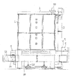
穀粒乾燥機は穀粒を収容する箱体1を備え、箱体1の前側は穀粒を揚穀する昇降機2と、熱風を発生させる燃焼バーナ4を内装する燃焼バーナ収容室5と、乾燥作業を操作する操作盤6とを備え、箱体1の天井側は昇降機2で揚穀した穀粒を箱体1内まで搬送する搬送装置3を備え、箱体1の後ろ側は箱体1内の熱風を吸引する排風ファン7を備え、箱体1の一側方には排風ファン7と燃焼バーナ収容室5とを連通する還元通路20を備えている。また、箱体1の他側方には穀粒を投入する投入口19を開閉する開閉扉19aを備えている。そして、昇降機2には穀粒の水分を検出する水分計9と箱体1内の穀粒を機外に排出する穀粒排出口18とをそれぞれ設け、搬送装置3の搬送途中には搬送装置3で搬送される穀粒に混じる藁屑等の夾雑物を集塵する集塵装置50を設ける。また操作盤6内には乾燥作業の制御をする制御部を備えている。
As one of the best modes for carrying out the present invention, a grain dryer will be described in detail.
The grain dryer includes a
箱体1内は上段に貯留室10を、下段に乾燥室11を備えている。
貯留室10の上部には搬送装置3内の上部ラセン3aで搬送された穀粒を貯留室10内に拡散する拡散羽根12を備えており、乾燥室11は燃焼バーナ4で発生させた熱風が通過する熱風室13と、貯留室10から穀粒が流下する流下通路14と、排風ファン7の吸引作用を受ける排風室15とから構成される。なお、燃焼バーナ4の燃焼面4aは熱風室13に対向する構成としている。流下通路14の下端部には流下通路14を流下した穀粒を所定量ずつ繰り出すロータリバルブ16を設け、ロータリバルブ16の下方にはロータリバルブ16で繰り出された穀粒を昇降機2に搬送する下部ラセン17を設けている。そして、排風ファン7の排出側と燃焼バーナ収容室5との間を還元通路20で連通する構成としている。
In the
The upper part of the
本実施例の還元通路21は箱体1の後側から側方を経由して前側の燃焼バーナ収容室5に接続する構成で、還元通路21を支持体25で支持する構成としている。
還元通路20には調節弁22を設けており、還元通路20側(図1実線)と機外排出通路23側(図1二点差線)とに開度自在に調節可能に構成することで、排風ファン7から排出された排風を機外への排出と熱風室13への還元との割合を調節できるようにしている。
The reduction passage 21 of the present embodiment is configured to be connected to the combustion
The reducing
なお、還元通路21には排風ファン7で排出された排風の温度を検出する排風温度センサ24と、排風の相対湿度を検出する排風湿度センサ25とを設けている。なお、本実施の形態の穀粒乾燥機においては、図示はしないが外気温の温度を検出する外気温センサや外気湿度を検出する外湿度センサを設けている。
The reduction passage 21 is provided with an exhaust
次に、乾燥作業について説明する。
作業者は開閉扉19aを開けて投入口19に穀粒を投入していく。投入された穀粒は下部ラセン17に供給され昇降機2まで搬送され、昇降機2から搬送装置3を経て貯留室10に供給されていく。供給すべき穀粒の投入が終了すると、作業者は操作盤6を操作して燃焼バーナ4を作動させると燃焼面4aに炎が発生し、熱風が熱風室13に供給される。一方、ロータリバルブ16も駆動を開始しており、流下通路14を流下する穀粒を順次下部ラセン17に繰り出していく。熱風室13に供給された熱風は熱風室13を形成する熱風室体13aに多数形成するスリット13bを通過して流下通路14に流入する。そして、流下する穀粒中の水分を奪って排風室15に流入する。そして、排風室15に流入した熱風は排風ファン7で吸引され還元通路20に排出される。
Next, the drying operation will be described.
The operator opens the opening / closing door 19 a and throws the grain into the
次に調節弁22の開度の制御方法について説明する。
外気温度センサで検出された外気温が20℃で外気湿度センサで検出された外気湿度が70%で制御部で演算された絶対湿度(Z)が13g/kgとする。そして、制御目標とする排風(Y)を例えば排風温度が30℃で排風湿度が70%、そして絶対湿度(U)を25g/kgとした場合とする。そして、本実施例の排風ファン7の風量を1900kg/hで、穀粒乾燥機に供給された穀粒(籾)量を800kg、乾減率(一時間あたりに乾燥される水分の割合)を1.2%/hとした場合、どの程度の割合の排風を熱風室13に還元するかを以下の式より求める。
Next, a method for controlling the opening degree of the
The outside air temperature detected by the outside air temperature sensor is 20 ° C., the outside air humidity detected by the outside air humidity sensor is 70%, and the absolute humidity (Z) calculated by the control unit is 13 g / kg. The exhaust air (Y) as a control target is, for example, the case where the exhaust air temperature is 30 ° C., the exhaust air humidity is 70%, and the absolute humidity (U) is 25 g / kg. And the air volume of the
絶対湿度(U)−絶対湿度(Z)=12(g/kg) …(イ)
実際に吸収できる水分量は
12×1900/1000=23(kg) …(ロ)
そして、一時間あたりに乾燥機から除去される水分量は
800(kg)×1.2(%/h)=9.6(kg/h) …(ハ)
(ロ)の式と(ハ)の式より
23/(9.6+23)=0.71 →71%…(二)
すなわち、排風ファン7から排出される排風量の71%を熱風室13に還元すべく調節弁22を調節する。
Absolute humidity (U)-Absolute humidity (Z) = 12 (g / kg) (B)
The amount of water that can actually be absorbed is 12 × 1900/1000 = 23 (kg) (b)
The amount of water removed from the dryer per hour is 800 (kg) × 1.2 (% / h) = 9.6 (kg / h) (C)
From the formulas (b) and (c) 23 / (9.6 + 23) = 0.71 → 71% (2)
In other words, the
なお、調節弁22が排風量の71%より多くの量を熱風室13に還元するよう調節された場合には、多くなればなるほど還元される水分量が多くなるため、穀粒から新たに水分を除去し難くなる。また、調節弁22が排風量の71%より少ない量を熱風室13に還元した場合には熱風室13に還元される熱量が少なくなるため、穀粒の温度の上昇がし難くなり乾燥速度が遅くなる。
In addition, when the
本実施例の式に基づいて調節弁22の開度を調節して排風を熱風室13に還元する割合を調節することで、排風ファン7から排出された排風が帯びる熱、すなわち吸水力をできる限り適正に利用することで燃焼効率の良い乾燥作業を行うことができる。
By adjusting the opening of the
なお、制御目標とする基準となる排風(Y)の絶対湿度(U)は、任意に設定変更できる構成としても良いし、乾燥工程の進行或いは外気温の変更に応じて自動に制御部で変更する構成としても良い。 Note that the absolute humidity (U) of the exhaust air (Y), which is the reference for the control target, may be configured to be arbitrarily set, or automatically by the control unit according to the progress of the drying process or the change of the outside air temperature. It is good also as a structure to change.
また、調節弁22で排風が機外に放出する割合と熱風室13に還元する割合は外気温度によって変更するよう制御しても良い。例えば、外気温度が約10℃の場合
熱風室13に還元する排風量の割合を70%程度になるよう調節弁22を調節し、外気温度が30℃近くなると、排風のほとんどを機外排出通路23から機外に排出する構成とする。この構成によると外気温が低いときには排風を効率よく使用して乾燥作業を行えるものでありながら、穀粒が傷むほどの穀粒温度(例えば35℃以上)への上昇を防止することができる。
Further, the rate at which the exhaust air is discharged outside the apparatus and the rate at which it is returned to the
ところで、還元通路20の調節弁22は乾燥作業開始時は排風を機外排出通路23側に排出される側の位置に設定している。すなわち、燃焼バーナ4の場合には燃焼バーナ4が立ち上がり燃焼状態が安定するまでの排風は循環させない構成としている。そして、燃焼状態が安定してから調節弁22を切り替えて排風を熱風室13に還元・循環させる構成にすることで、乾燥初期の燃焼が安定していないときの排風が熱風室13に入り込むことを防止することができる。
By the way, the
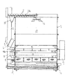
また、還元通路20から燃焼バーナ収容室5の側方に流入した排風は、燃焼バーナ収容室5の前側に設けた外気取り入れ口5aから流入した外気と共に燃焼バーナ4の前側から熱風室13に供給される。燃焼バーナ4の場合に、燃焼面4aの側方から排風が供給されると燃焼炎に乱れが生じ、燃焼が不安定になるが、燃焼バーナ4の前側からすなわち、燃焼面4aと反対方向から排風及び外気を供給する構成としたことで、燃焼面4aの炎の乱れを防止することができる。また、外気を遮断するダンパ等を必要とせず、略一定量の外気を導入しながら排風循環を可能とした。
Further, the exhaust air flowing into the side of the combustion
30は排風を絞り込むためのガイドで調節弁22の前工程に備えている。このガイドにより調節弁22が作動したときに排風が排風ファン7側に戻ることを防止することができる。
本発明の別実施例について説明する。
燃焼バーナ4の作動が開始され、燃焼状態が安定した後、調節弁22が全閉状態にして還元通路20の排風を燃焼バーナ収容室5に還元する。そして、排風湿度センサ25が所定時間ごとに排風の相対湿度を検出していき、排風の相対湿度が予め設定した上限の相対湿度(例えば90%)になったことを検出すると、調節弁22を開方向に作動して排風を機外に排出し、その後排風湿度センサ25で検出した相対湿度が設定した下限相対湿度(例えば70%)以下まで低下したことを検出すると、再度調節弁22を閉状態にして排風を循環する構成とする。この構成により、排風に多くの水分を吸収させてから排出し、湿度の高くなった排風を排出してから再度調節弁22を閉状態にして排風を循環させることで、燃焼効率の良い排風の循環制御を行うことができる。
Another embodiment of the present invention will be described.
After the operation of the
次に高速で乾燥できる穀粒乾燥機の別実施例について図7〜図9に基づいて説明する。
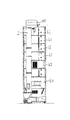
この穀粒乾燥機の特徴は第一乾燥室60の上方に同じ高さの枠体61を複数段段積みする構成であるが、そのうちの一つの段に加温装置を備えた第二乾燥室62を形成したものである。この第二乾燥室62は熱源として燃焼バーナあるいは電熱ヒータを用いている。第二乾燥室62の枠体とその他の段の枠体を同じ高さHに形成することで、所望の段に第二乾燥室62を備えることができる。また、第一乾燥室60、第二乾燥室62の何れにもそれぞれ排風ファン60a,62aを設けている。
Next, another embodiment of a grain dryer capable of drying at high speed will be described with reference to FIGS.
A feature of this grain dryer is a configuration in which a plurality of
なお、この第二乾燥室62内は自然に穀粒が流下する構成にしてロータリバルブ等の繰り出し手段を設けないことで穀粒の詰まりを防止することができるものである。
この実施例の穀粒乾燥機によると、さまざまな乾燥制御方法を行うことができる。例えば、第一乾燥室60に近い段に第二乾燥室62を備えると第二乾燥室62で予熱してすぐに第一乾燥室60で本乾燥を行ういわゆる高速乾燥制御を行ったり、第二乾燥室62を上段に近い位置に配置すれば第二乾燥室62による乾燥工程があり次にテンパリング工程そして第一乾燥室60による乾燥工程と一台の乾燥機で二段乾燥サイクルを行えるようにする。
It should be noted that the inside of the
According to the grain dryer of this embodiment, various drying control methods can be performed. For example, when the
また、第一乾燥室62を遠赤外線乾燥装置を備え、第二乾燥室を電熱ヒータを備える等、異なる加熱方法の組み合わせにするものでも良い。
Further, the
本実施の形態では還元通路20を箱体1の外側に設けているものであるが、箱体1の内部を貫通する構成にしても良い。
In the present embodiment, the
4 燃焼装置(燃焼バーナ)
7 排風ファン
13 熱風室
15 排風室
20 還元通路
22 調節弁
4 Combustion device (combustion burner)
7
Claims (2)
熱風室(13)の前側に燃焼装置(4)を設け、後側に排風ファン(7)を設け、排風ファン(7)の排出側には排風ファン(7)から排出された排風が通過する還元通路(20)を設け、該還元通路(20)には機外側に放出する排風と熱風室(13)側に還元する排風の割合を調節する調節弁(22)を設け、
前記制御部で演算した外気の絶対湿度と制御目標とする排風の絶対湿度との差から、排風が穀粒から吸収できる吸水量を演算し、該演算結果と予め設定する乾減率に基づいて熱風室(13)に還元する排風の割合を変更すべく前記調節弁(22)を調節する構成とし、
機外側に放出する排風と熱風室(13)側に還元する排風の割合を、外気温度が高くなると機外側に排出する排風の割合を高くするよう調節弁(22)を変更制御することを特徴とする穀粒乾燥機。 Combustion device (4) for generating hot air for drying the grain, hot air chamber (13) through which the hot air generated by the combustion device (4) passes, and drying the kernel to absorb moisture in the kernel An exhaust chamber (15) into which hot air flows, an exhaust fan (7) that sucks the hot air flowing into the exhaust chamber (15) and discharges it as exhaust air, an outside air temperature sensor that detects the outside air temperature, In a grain dryer provided with a control unit for controlling the drying operation,
The combustion device (4) is provided on the front side of the hot air chamber (13), the exhaust air fan (7) is provided on the rear side, and the exhaust air discharged from the exhaust air fan (7) is provided on the exhaust side of the exhaust air fan (7). A reduction passage (20) through which wind passes is provided, and the reduction passage (20) is provided with a regulating valve (22) for adjusting the ratio of the exhaust air discharged to the outside of the machine and the exhaust air reduced to the hot air chamber (13). Provided,
From the difference between the absolute humidity of the outside air calculated by the control unit and the absolute humidity of the exhaust air as a control target, the water absorption amount that the exhaust air can absorb from the grain is calculated, and the calculation result and a preset drying rate are calculated. Based on the configuration, the control valve (22) is adjusted to change the ratio of the exhaust air that is reduced to the hot air chamber (13).
The control valve (22) is changed and controlled so that the ratio of the exhausted air discharged to the outside of the apparatus and the exhausted air reduced to the hot air chamber (13) side is increased when the outside air temperature becomes high. A grain dryer characterized by that.
Priority Applications (1)
| Application Number | Priority Date | Filing Date | Title |
|---|---|---|---|
| JP2005192934A JP4379388B2 (en) | 2005-06-30 | 2005-06-30 | Grain dryer |
Applications Claiming Priority (1)
| Application Number | Priority Date | Filing Date | Title |
|---|---|---|---|
| JP2005192934A JP4379388B2 (en) | 2005-06-30 | 2005-06-30 | Grain dryer |
Publications (3)
| Publication Number | Publication Date |
|---|---|
| JP2007010247A JP2007010247A (en) | 2007-01-18 |
| JP2007010247A5 JP2007010247A5 (en) | 2007-11-22 |
| JP4379388B2 true JP4379388B2 (en) | 2009-12-09 |
Family
ID=37748993
Family Applications (1)
| Application Number | Title | Priority Date | Filing Date |
|---|---|---|---|
| JP2005192934A Expired - Fee Related JP4379388B2 (en) | 2005-06-30 | 2005-06-30 | Grain dryer |
Country Status (1)
| Country | Link |
|---|---|
| JP (1) | JP4379388B2 (en) |
Cited By (1)
| Publication number | Priority date | Publication date | Assignee | Title |
|---|---|---|---|---|
| JP2009287831A (en) * | 2008-05-29 | 2009-12-10 | Iseki & Co Ltd | Exhaust air circulation type grain drier |
Families Citing this family (11)
| Publication number | Priority date | Publication date | Assignee | Title |
|---|---|---|---|---|
| JP4992442B2 (en) * | 2007-01-31 | 2012-08-08 | 井関農機株式会社 | Grain dryer |
| JP5040384B2 (en) * | 2007-03-16 | 2012-10-03 | 井関農機株式会社 | Exhaust circulation type grain dryer |
| JP5251029B2 (en) * | 2007-07-20 | 2013-07-31 | 井関農機株式会社 | Kernel drying method |
| JP5125419B2 (en) * | 2007-10-31 | 2013-01-23 | 井関農機株式会社 | Drying equipment |
| JP5298647B2 (en) * | 2008-06-02 | 2013-09-25 | 井関農機株式会社 | Grain dryer |
| JP5422965B2 (en) * | 2008-10-24 | 2014-02-19 | 井関農機株式会社 | Exhaust air circulation type grain dryer |
| KR101261477B1 (en) * | 2010-04-13 | 2013-05-10 | 김광영 | Heat recovery type drying system |
| JP5310786B2 (en) * | 2011-05-30 | 2013-10-09 | 井関農機株式会社 | Dryer |
| JP5267634B2 (en) * | 2011-10-28 | 2013-08-21 | 井関農機株式会社 | Grain dryer |
| JP5510573B2 (en) * | 2013-02-26 | 2014-06-04 | 井関農機株式会社 | Exhaust air circulation type grain dryer |
| US10782069B2 (en) * | 2014-06-10 | 2020-09-22 | Ctb, Inc. | Equilibrium moisture grain drying with heater and variable speed fan |
-
2005
- 2005-06-30 JP JP2005192934A patent/JP4379388B2/en not_active Expired - Fee Related
Cited By (1)
| Publication number | Priority date | Publication date | Assignee | Title |
|---|---|---|---|---|
| JP2009287831A (en) * | 2008-05-29 | 2009-12-10 | Iseki & Co Ltd | Exhaust air circulation type grain drier |
Also Published As
| Publication number | Publication date |
|---|---|
| JP2007010247A (en) | 2007-01-18 |
Similar Documents
| Publication | Publication Date | Title |
|---|---|---|
| JP4379388B2 (en) | Grain dryer | |
| JP2007010247A5 (en) | ||
| US9091014B2 (en) | Clothing dryer and control method thereof | |
| CN1180218C (en) | Method for drying granular material and its device containing preheating process | |
| JP5729355B2 (en) | Drying equipment | |
| JP4696940B2 (en) | Grain dryer | |
| JP2009024948A (en) | Dryer | |
| JP2007205600A5 (en) | ||
| JP5152283B2 (en) | Grain dryer | |
| JP5267634B2 (en) | Grain dryer | |
| JP5040384B2 (en) | Exhaust circulation type grain dryer | |
| JP4992442B2 (en) | Grain dryer | |
| JP5402950B2 (en) | Grain dryer | |
| KR100276816B1 (en) | Circulating Grain Dryer with Improved Drying Hot Air Supply and Discharge Paths | |
| JP2008045865A (en) | Grain dryer | |
| JP2008185311A5 (en) | ||
| JP4362673B2 (en) | Discharge valve control device for circulating grain dryer | |
| RU2128917C1 (en) | Plant for grain drying in fluidized bed | |
| JP2005073546A (en) | Conveying belt steamer | |
| JPH02306085A (en) | Controlling method for drying of cereals drier | |
| JPH01244271A (en) | Grain drier | |
| JPH116685A (en) | Circulating grain drier | |
| JP4374733B2 (en) | Grain dryer | |
| JPH0313783A (en) | Control system of drying of grain drier | |
| JP2005265262A (en) | Sawdust drying device |
Legal Events
| Date | Code | Title | Description |
|---|---|---|---|
| A521 | Request for written amendment filed |
Free format text: JAPANESE INTERMEDIATE CODE: A523 Effective date: 20071005 |
|
| A621 | Written request for application examination |
Free format text: JAPANESE INTERMEDIATE CODE: A621 Effective date: 20071005 |
|
| A977 | Report on retrieval |
Free format text: JAPANESE INTERMEDIATE CODE: A971007 Effective date: 20081015 |
|
| A131 | Notification of reasons for refusal |
Free format text: JAPANESE INTERMEDIATE CODE: A131 Effective date: 20081209 |
|
| A521 | Request for written amendment filed |
Free format text: JAPANESE INTERMEDIATE CODE: A523 Effective date: 20090119 |
|
| TRDD | Decision of grant or rejection written | ||
| A01 | Written decision to grant a patent or to grant a registration (utility model) |
Free format text: JAPANESE INTERMEDIATE CODE: A01 Effective date: 20090825 |
|
| A01 | Written decision to grant a patent or to grant a registration (utility model) |
Free format text: JAPANESE INTERMEDIATE CODE: A01 |
|
| A61 | First payment of annual fees (during grant procedure) |
Free format text: JAPANESE INTERMEDIATE CODE: A61 Effective date: 20090907 |
|
| FPAY | Renewal fee payment (event date is renewal date of database) |
Free format text: PAYMENT UNTIL: 20121002 Year of fee payment: 3 |
|
| R150 | Certificate of patent or registration of utility model |
Ref document number: 4379388 Country of ref document: JP Free format text: JAPANESE INTERMEDIATE CODE: R150 Free format text: JAPANESE INTERMEDIATE CODE: R150 |
|
| FPAY | Renewal fee payment (event date is renewal date of database) |
Free format text: PAYMENT UNTIL: 20121002 Year of fee payment: 3 |
|
| FPAY | Renewal fee payment (event date is renewal date of database) |
Free format text: PAYMENT UNTIL: 20151002 Year of fee payment: 6 |
|
| LAPS | Cancellation because of no payment of annual fees |