JP4372896B2 - Method for manufacturing electro-optical device - Google Patents
Method for manufacturing electro-optical device Download PDFInfo
- Publication number
- JP4372896B2 JP4372896B2 JP19108199A JP19108199A JP4372896B2 JP 4372896 B2 JP4372896 B2 JP 4372896B2 JP 19108199 A JP19108199 A JP 19108199A JP 19108199 A JP19108199 A JP 19108199A JP 4372896 B2 JP4372896 B2 JP 4372896B2
- Authority
- JP
- Japan
- Prior art keywords
- type impurity
- film
- active layer
- forming
- mask
- Prior art date
- Legal status (The legal status is an assumption and is not a legal conclusion. Google has not performed a legal analysis and makes no representation as to the accuracy of the status listed.)
- Expired - Fee Related
Links
Images


Description
【0001】
【発明の属する技術分野】
本発明は絶縁表面を有する基板上に薄膜トランジスタ(以下、TFTという)で構成された素子又は回路を有する電気光学装置の作製方法に関する。また、本願発明を用いた作製された電気光学装置を具備する電子装置に関する。
【0002】
【従来の技術】
基板上にTFTで形成した集積回路を有する電気光学装置の開発が進んでいる。液晶表示装置、EL表示装置、又は密着型イメージセンサはその代表例として知られている。特に、ポリシリコン膜(多結晶シリコン膜)を活性層にしたTFT(以下、poly-SiTFTと記す)は従来のアモルファスシリコン膜を用いたTFT(以下、a-SiTFTと記す)よりも電界効果移動度が高いことから注目されている。
【0003】
poly-SiTFTを用いた電気光学装置としては、現在液晶表示装置が非常に注目され、既に市場に現れ始めている。しかしながら、poly-SiTFTは高性能ではあるが、a-SiTFTに比べて製造コストが高い。従って、poly-SiTFTの製造コストを低減することが、poly-SiTFTを用いた液晶表示装置の市場を確保する上で重要な問題となってきている。
【0004】
【発明が解決しようとする課題】
本願発明は、TFTの製造コストを低減することにより、TFTを用いた電気光学装置の製造コストを低減するための技術を提供することを課題とする。そして、電気光学装置の製造コストを低減する技術を提供することにより、その電気光学装置を具備した電子装置の製造コストを低減することを課題とする。
【0005】
【課題を解決するための手段】
本願発明では、TFTの製造過程で用いられるパターニング工程(フォトリソグラフィ工程)の回数を極力抑えることにより、製造コストの低減を達成する。このパターニング工程の削減のために、ゲート電極を形成した後、新たにパターニング工程を施すことなく前記ゲート電極の側壁にドーピングマスクとなりうる部材を形成する。これによりパターニング工程を増やすことなくLDD領域を形成することが容易となる。
【0006】
【発明の実施の形態】
本発明の実施の形態について、以下に示す実施例でもって詳細な説明を行うこととする。
【0007】
[実施例1]
本発明の実施例について図1〜図4を用いて説明する。ここでは、画素部とその周辺に設けられる駆動回路を同時に作製する方法について説明する。但し、説明を簡単にするために、駆動回路に関しては、シフトレジスタ回路、バッファ回路等の基本回路であるCMOS回路と、サンプリング回路を形成するnチャネル型TFTとを図示することとする。
【0008】
図1(A)において、基板101には、ガラス基板や石英基板を使用することが望ましい。その他にもシリコン基板、金属基板またはステンレス基板の表面に絶縁膜を形成したものを基板としても良い。耐熱性が許せばプラスチック基板を用いることも可能である。
【0009】
そして、基板101のTFTが形成される表面には、珪素(シリコン)を含む絶縁膜(本明細書中では酸化シリコン膜、窒化シリコン膜、または窒化酸化シリコン膜の総称を指す)からなる下地膜102をプラズマCVD法やスパッタ法で100〜400nmの厚さに形成する。
【0010】
なお、本明細書中において窒化酸化シリコン膜とはSiOxNyで表される絶縁膜であり、珪素、酸素、窒素を所定の割合で含む絶縁膜を指す。本実施例では、下地膜102として、窒素を20〜50atomic%(典型的には20〜30atomic%)で含む100nm厚の窒化酸化シリコン膜と、窒素を1〜20atomic%(典型的には5〜10atomic%)で含む200nm厚の窒化酸化シリコン膜との積層膜を用いる。なお、厚さはこの値に限定する必要はない。また、窒化酸化シリコン膜に含まれる窒素と酸素の含有比(atomic%比)は3:1〜1:3(典型的には1:1)とすればよい。また、窒化酸化シリコン膜は、SiH4とN2OとNH3を原料ガスとして作製すればよい。
【0011】
なお、この下地膜101は基板からの不純物汚染を防ぐために設けられるものであり、石英基板を用いた場合には必ずしも設けなくても良い。
【0012】
次に下地膜102の上に30〜120nm(好ましくは50〜70nm)の厚さの、アモルファスシリコン膜(図示せず)を公知の成膜法で形成する。なお、アモルファスシリコン膜に限定する必要はなく、非晶質構造を含む半導体膜であれば良い。非晶質構造を含む半導体膜としては、非晶質半導体膜、微結晶半導体膜があり、さらにアモルファス構造のシリコンゲルマニウム膜などの非晶質構造を含む化合物半導体膜も含まれる。また、上記膜厚で形成しておけば、最終的にTFTが完成した時点の活性層の膜厚は10〜100nm(好ましくは30〜50nm)となる。
【0013】
そして、特開平7−130652号公報(USP5,643,826号に対応)に記載された技術に従って、ポリシリコン膜103を形成する。同公報記載の技術は、アモルファスシリコン膜の結晶化に際して、結晶化を助長する触媒元素(ニッケル、コバルト、ゲルマニウム、錫、鉛、パラジウム、鉄、銅から選ばれた一種または複数種の元素、代表的にはニッケル)を用いる結晶化手段である。
【0014】
具体的には、アモルファスシリコン膜表面に触媒元素を保持させた状態で加熱処理を行い、アモルファスシリコン膜をポリシリコン膜に変化させるものである。本実施例では同公報の実施例1に記載された技術を用いるが、実施例2に記載された技術を用いても良い。なお、本実施例ではポリシリコン膜を例にしているが、ポリシリコン膜に限定する必要はなく、結晶質構造を含む半導体膜(単結晶シリコン膜も含む)であれば良い。(図1(A))
【0015】
アモルファスシリコン膜は含有水素量にもよるが、好ましくは400〜550℃で数時間加熱して脱水素処理を行い、含有水素量を5atom%以下として、結晶化の工程を行うことが望ましい。また、アモルファスシリコン膜をスパッタ法や蒸着法などの他の作製方法で形成しても良いが、膜中に含まれる酸素、窒素などの不純物元素を十分低減させておくことが望ましい。
【0016】
ここでは、下地膜とアモルファスシリコン膜とは、同じ成膜法で形成することが可能であるので両者を連続形成しても良い。下地膜を形成後、一旦大気雰囲気にさらされないようにすることで表面の汚染を防ぐことが可能となり、作製されるTFTの特性バラツキを低減させることができる。
【0017】
次に、ポリシリコン膜103に対してレーザー光源から発する光(レーザー光)を照射(以下、レーザーアニールという)して結晶性の改善されたポリシリコン膜104を形成する。レーザー光としては、パルス発振型または連続発振型のエキシマレーザー光が望ましいが、連続発振型のアルゴンレーザー光でも良い。また、レーザー光のビーム形状は線状であっても矩形状であっても構わない。(図1(B))
【0018】
また、レーザー光の代わりにランプから発する光(以下、ランプ光という)を照射(以下、ランプアニールという)しても良い。ランプ光としては、ハロゲンランプ、赤外ランプ等から発するランプ光を用いることができる。
【0019】
なお、このようにレーザー光またはランプ光により熱処理(アニール)を施す工程を光アニール工程という。光アニール工程は短時間で高温熱処理が行えるため、ガラス基板等の耐熱性の低い基板を用いる場合にも効果的な熱処理工程を高いスループットで行うことができる。勿論、目的はアニールであるので電熱炉を用いたファーネスアニール(熱アニールともいう)で代用することもできる。
【0020】
本実施例では、パルス発振型エキシマレーザー光を線状に加工してレーザーアニール工程を行う。レーザーアニール条件は、励起ガスとしてXeClガスを用い、処理温度を室温、パルス発振周波数を30Hzとし、レーザーエネルギー密度を250〜500mJ/cm2(代表的には350〜400mJ/cm2)とする。
【0021】
上記条件で行われたレーザーアニール工程は、熱結晶化後に残存した非晶質領域を完全に結晶化すると共に、既に結晶化された結晶質領域の欠陥等を低減する効果を有する。そのため、本工程は光アニールにより半導体膜の結晶性を改善する工程、または半導体膜の結晶化を助長する工程と呼ぶこともできる。このような効果はランプアニールの条件を最適化することによっても得ることが可能である。本明細書中ではこのような条件を第1アニール条件と呼ぶことにする。
【0022】
次に、ポリシリコン膜104をパターニングして島状の半導体膜(以下、活性層という)105〜108を形成する。ここで1回目のパターニング工程が行われる。なお、このとき同時に、今後のパターニング時の位置合わせに用いるアライメントマーカーを、ポリシリコン膜を用いて形成する。本実施例の場合、活性層の形成と同時にアライメントマーカーを形成することができるため、アライメントマーカーを別途形成する手間(パターニング工程の増加)を防ぐことができる。
【0023】
次に、活性層105〜108上に後の不純物添加時のために保護膜109を形成する。保護膜109は100〜200nm(好ましくは130〜170nm)の厚さの窒化酸化シリコン膜または酸化シリコン膜を用いる。この保護膜109は不純物添加時にポリシリコン膜が直接プラズマに曝されないようにするためと、微妙な濃度制御を可能にするための意味がある。(図1(C))
【0024】
そして、保護膜109を介してp型を付与する不純物元素(以下、p型不純物元素という)を添加する。p型不純物元素としては、代表的には13族に属する元素、典型的にはボロンまたはガリウムを用いることができる。この工程(チャネルドープ工程という)はTFTのしきい値電圧を制御するための工程である。なお、ここではジボラン(B2H6)を質量分離しないでプラズマ励起したイオンドープ法でボロンを添加する。勿論、質量分離を行うイオンインプランテーション法を用いても良い。
【0025】
こうして1×10¹⁵〜1×10¹⁸atoms/cm3(代表的には5×1016〜5×1017atoms/cm3)の濃度でp型不純物元素(本実施例ではボロン)が添加された活性層110〜113が形成される。但し、本明細書中で記載する濃度は全てSIMS(質量二次イオン分析)による測定値である。なお、本明細書中では少なくとも上記濃度範囲でp型不純物元素を含む不純物領域(但し、1×1016atoms/cm3の濃度でn型を付与する不純物元素、典型的にはリン又は砒素が添加された領域を除く)をp型不純物領域(b)と定義する。(図1(D))
【0026】
また、この工程では後のpチャネル型TFTの活性層110にもボロンが添加されているが、必要がなければ活性層110のみレジストマスクで隠して上記工程を行っても良いし、全面のボロンを添加した後、活性層110のみに15族に属する元素(代表的にはリン又は砒素)を添加してさらにしきい値電圧を調節しても良い。但し、いずれにしてもパターニング回数は増加してしまう。
【0027】
次に、レジストマスク114a〜114dを形成する。ここで2回目のパターニング工程が行われる。そして、n型を付与する不純物元素(以下、n型不純物元素という)を添加してn型を呈する不純物領域115〜118を形成する。なお、n型不純物元素としては、代表的には15族に属する元素、典型的にはリンまたは砒素を用いることができる。(図1(E))
【0028】
この低濃度不純物領域115〜118は、後にCMOS回路又はサンプリング回路のnチャネル型TFTにおいて、LDD領域となる不純物領域、若しくは保持容量の下部電極となる領域である。なお、ここで形成された不純物領域にはn型不純物元素が2×10¹⁶〜5×10¹⁹atoms/cm3(代表的には5×1017〜5×1018atoms/cm3)の濃度で含まれている。本明細書中では上記濃度範囲でn型不純物元素を含む不純物領域をn型不純物領域(b)と定義する。
【0029】
なお、ここではフォスフィン(PH3)を質量分離しないでプラズマ励起したイオンドープ法でリンを1×10¹⁸atoms/cm3の濃度で添加する。勿論、質量分離を行うイオンインプランテーション法を用いても良い。この工程では、保護膜109を介してポリシリコン膜にリンを添加する。
【0030】
次に、レジストマスク114a〜114d及び保護膜109を除去し、再びレーザー光の照射工程を行う。ここでもレーザー光としては、パルス発振型または連続発振型のエキシマレーザー光が望ましいが、連続発振型のアルゴンレーザー光でも良い。また、レーザー光のビーム形状は線状であっても矩形状であっても構わない。但し、添加された不純物元素の活性化が目的であるので、ポリシリコン膜が溶融しない程度のエネルギーで照射することが好ましい。また、保護膜109をつけたままレーザーアニール工程を行うことも可能である。(図1(F))
【0031】
本実施例では、パルス発振型エキシマレーザー光を線状に加工してレーザーアニール工程を行う。レーザーアニール条件は、励起ガスとしてKrFガスを用い、処理温度を室温、パルス発振周波数を30Hzとし、レーザーエネルギー密度を100〜300mJ/cm2(代表的には150〜250mJ/cm2)とする。
【0032】
上記条件で行われた光アニール工程は、添加されたn型またはp型を付与する不純物元素を活性化すると共に、不純物元素の添加時に非晶質化した半導体膜を再結晶化する効果を有する。なお、上記条件は半導体膜を溶融させることなく原子配列の整合性をとり、且つ、不純物元素を活性化することが好ましい。また、本工程は光アニールによりn型またはp型を付与する不純物元素を活性化する工程、半導体膜を再結晶化する工程、またはそれらを同時に行う工程と呼ぶこともできる。このような効果はランプアニールの条件を最適化することによっても得ることが可能である。本明細書中ではこのような条件を第2アニール条件と呼ぶことにする。
【0033】
この工程によりn型不純物領域(b)115〜118の境界部、即ち、n型不純物領域(b)の周囲に存在する真性な領域(p型不純物領域(b)も実質的に真性とみなす)との接合部が明確になる。このことは、後にTFTが完成した時点において、LDD領域とチャネル形成領域とが非常に良好な接合部を形成しうることを意味する。
【0034】
なお、このレーザー光による不純物元素の活性化に際して、電熱炉を用いた熱処理による活性化を併用しても構わない。熱処理による活性化を行う場合は、基板の耐熱性を考慮して450〜650℃(好ましくは500〜550℃)の熱処理を行えば良い。
【0035】
次に、活性層110〜113を覆ってゲート絶縁膜119を形成する。ゲート絶縁膜119は、10〜200nm、好ましくは50〜150nmの厚さに形成すれば良い。本実施例では、プラズマCVD法でN2OとSiH4を原料とした窒化酸化シリコン膜を80nmの厚さに形成する。(図2(A))
【0036】
次に、ゲート配線(ゲート電極も含む)となる導電膜120を形成する。なお、ゲート配線は単層の導電膜で形成しても良いが、必要に応じて二層、三層といった積層膜とすることが好ましい。
【0037】
ここで導電膜120としては、タンタル(Ta)、チタン(Ti)、モリブデン(Mo)、タングステン(W)、クロム(Cr)、ニオブ(Nb)、シリコン(Si)から選ばれた元素を含む金属膜、または前記元素を主成分とする金属化合物膜(代表的には窒化タンタル膜、窒化タングステン膜、窒化チタン膜)、または前記元素を組み合わせた合金膜(代表的にはMo−W合金膜、Mo−Ta合金膜、タングステンシリサイド膜)、若しくはそれらの薄膜を積層した積層膜を用いることができる。
【0038】
本実施例では、導電膜120として、50nm厚の窒化タンタル(TaN)膜と、350nm厚のタンタル(Ta)膜でなる積層膜を用いる。
【0039】
このほか、窒化タングステン膜とタングステン膜との積層膜、窒化タンタル膜のみの単層膜、タングステンシリサイド膜も好適である。また、ゲート配線の最下層にシリコン膜を2〜20nm程度の厚さで形成する構造(ポリサイド構造)とすると、シリコン膜上に形成された導電膜の密着性を向上させると同時に、導電膜の酸化を抑制することができる。
【0040】
また、本実施例のように導電膜120として金属膜を用いた場合、その表面をアンモニアガスまたは窒素ガスを用いたプラズマ雰囲気に曝すことで窒化することも有効である。こうすることで、金属膜表面の酸化を抑制することが可能である。
【0041】
次に、レジストマスク121a〜121fを形成し、導電膜120をエッチングして400nm厚のゲート配線122〜124、125a、125b及び保持容量の上部電極となる容量配線126を形成する。ここで3回目のパターニング工程が行われる。この時、駆動回路に形成されるゲート配線123、124はn型不純物領域(b)115〜117の一部とゲート絶縁膜を介して重なるように形成する。なお、ゲート配線125a、125bは断面では二つに見えるが、実際は連続的に繋がった一つのパターンから形成されている。(図2(B))
【0042】
次に、ゲート配線122〜124、125a、125b及び容量配線126をマスクとして自己整合的にn型不純物元素(本実施例ではリン)を添加する。こうして形成された不純物領域127〜132にはn型不純物領域(b)の1/2〜1/10(代表的には1/3〜1/4)の濃度(但し、前述のチャネルドープ工程で添加されたボロン濃度よりも5〜10倍高い濃度、代表的には1×1016〜5×1018atoms/cm3、典型的には3×1017〜3×1018atoms/cm3、)でリンが添加されるように調節する。なお、本明細書中では上記濃度範囲でn型不純物元素を含む不純物領域をn型不純物領域(c)と定義する。(図2(C))
【0043】
なお、n型不純物領域(c)127〜132には既にチャネルドープ工程で1×10¹⁵〜1×10¹⁸atoms/cm3の濃度のボロンが添加されているが、この工程ではp型不純物領域(b)に含まれるボロンの5〜10倍の濃度でリンが添加されるので、ボロンの影響は無視して良い。
【0044】
但し、厳密にはn型不純物領域(b)115〜117のうちゲート配線に重なった部分のリン濃度が2×10¹⁶〜5×10¹⁹atoms/cm3のままであるのに対し、ゲート配線に重ならない部分はそれに1×1016〜5×1018atoms/cm3の濃度のリンが加わっており、若干高い濃度でリンを含むことになる。
【0045】
次に、レジストマスク121a〜121fを除去し、絶縁物でなるサイドウォール133〜138を形成する。サイドウォールの形成方法は公知の技術を用いれば良いが、好ましくは厚めに形成した絶縁膜をドライエッチング法によりエッチングしてゆく方法(エッチバックと呼ばれる技術)を用いた方法が良い。本実施例では窒化シリコン膜を用いて形成する。(図2(D))
【0046】
次に、サイドウォール133〜138をマスクとして、再びn型不純物元素の添加工程を行う。こうして高濃度にリンを含む不純物領域139〜148を形成する。ここでは、フォスフィン(PH3)を用いたイオンドープ法(勿論、イオンインプランテーション法でも良い)で行い、この領域のリンの濃度は1×10²⁰〜1×10²¹atoms/cm3(代表的には2×1020〜5×1021atoms/cm3)とする。なお、本明細書中では上記濃度範囲でn型不純物元素を含む不純物領域をn型不純物領域(a)と定義する。(図3(A))
【0047】
次に、レジストマスク149を形成する。ここで4回目のパターニング工程が行われる。そして、p型不純物元素(本実施例ではボロン)を添加し、高濃度にボロンを含む不純物領域150、151を形成する。ここではジボラン(B2H6)を用いたイオンドープ法(勿論、イオンインプランテーション法でも良い)により3×10²⁰〜3×10²¹atoms/cm3(代表的には5×1020〜1×1021atoms/cm3)濃度でボロンを添加する。なお、本明細書中では上記濃度範囲でp型不純物元素を含む不純物領域をp型不純物領域(a)と定義する。(図3(B))
【0048】
なお、不純物領域150、151の一部(前述のn型不純物領域(a)139、140)には既に1×10²⁰〜1×10²¹atoms/cm3の濃度でリンが添加されているが、ここで添加されるボロンはその少なくとも3倍以上の濃度で添加される。そのため、予め形成されていたn型の不純物領域は完全にP型に反転し、P型の不純物領域として機能する。
【0049】
次に、レジストマスク149を除去した後、第1層間絶縁膜152を形成する。第1層間絶縁膜152としては、珪素を含む絶縁膜、具体的には窒化シリコン膜、酸化シリコン膜、窒化酸化シリコン膜またはそれらを組み合わせた積層膜で形成すれば良い。また、膜厚は50〜400nm(好ましくは100〜200nm)とすれば良い。
【0050】
本実施例では、プラズマCVD法でSiH4、N2O、NH3を原料ガスとし、200nm厚の窒化酸化シリコン膜(但し窒素濃度が25〜50atomic%)を用いる。この第1層間絶縁膜152は次に行われる熱処理工程(活性化工程)において、ゲート配線122〜124、125a、125b及び容量配線126が酸化されて抵抗値が増加するのを防ぐ効果を有する。
【0051】
その後、それぞれの濃度で添加されたn型またはp型不純物元素を活性化するために熱処理工程(活性化工程)を行う。この工程はファーネスアニール法、レーザーアニール法、またはラピッドサーマルアニール法(RTA法)で行うことができる。ここではファーネスアニール法で活性化工程を行う。この熱処理工程は、窒素雰囲気中において300〜650℃、好ましくは400〜550℃、ここでは550℃、4時間の熱処理を行う。(図3(C))
【0052】
この時、本実施例においてアモルファスシリコン膜の結晶化に用いた触媒元素(本実施例ではニッケル)が、矢印で示す方向に移動して、前述の図3(A)の工程で形成された高濃度にリンを含む領域に捕獲(ゲッタリング)される。これはリンによる金属元素のゲッタリング効果に起因する現象であり、この結果、後のチャネル形成領域153〜157は前記触媒元素の濃度が1×10¹⁷atoms/cm3以下となる。但し、ニッケルの場合、1×1017atoms/cm3以下はSIMSの測定下限となるため、現状の技術では測定不能である。
【0053】
また、逆に触媒元素のゲッタリングサイトとなった領域(図3(A)の工程で不純物領域139〜148が形成された領域)は高濃度に触媒元素が偏析して5×10¹⁸atoms/cm3以上(代表的には1×1019〜5×1020atoms/cm3)濃度で存在するようになる。しかし、このゲッタリングサイトとなった領域はソース領域またはドレイン領域として機能すれば良いので、ニッケルの有無は問題とはならないと考えられる。
【0054】
次に、3〜100%の水素を含む雰囲気中で、300〜450℃で1〜12時間の熱処理を行い、活性層を水素化する工程を行う。この工程は熱的に励起された水素により半導体層のダングリングボンドを終端する工程である。水素化の他の手段として、プラズマ水素化(プラズマにより励起された水素を用いる)を行っても良い。
【0055】
活性化工程を終えたら、第1層間絶縁膜152の上に500nm〜1.5μm厚の第2層間絶縁膜158を形成する。本実施例では第2層間絶縁膜158として800nm厚の酸化シリコン膜をプラズマCVD法により形成する。こうして第1層間絶縁膜(窒化酸化シリコン膜)152と第2層間絶縁膜(酸化シリコン膜)158との積層膜でなる1μm厚の層間絶縁膜を形成する。(図3(D))
【0056】
なお、第2層間絶縁膜158として、ポリイミド、アクリル、ポリアミド、ポリイミドアミド、BCB(ベンゾシクロブテン)等の有機樹脂絶縁膜を用いることも可能である。
【0057】
その後、それぞれのTFTのソース領域またはドレイン領域に達するコンタクトホールが形成される。ここで5回目のパターニング工程が行われる。そして、ソース配線159〜162と、ドレイン配線163〜166を形成する。ここで6回目のパターニング工程が行われる。
【0058】
なお、図示されていないがCMOS回路を形成するためにドレイン配線163、164は電気的に接続されている。また、本実施例ではこの電極を、Ti膜を100nm、Tiを含むアルミニウム膜300nm、Ti膜150nmをスパッタ法で連続して形成した3層構造の積層膜とする。
【0059】
次に、パッシベーション膜167として、窒化シリコン膜、酸化シリコン膜、または窒化酸化シリコン膜で50〜500nm(代表的には200〜300nm)の厚さで形成する。
【0060】
この時、膜の形成に先立ってH2、NH3等水素を含むガスを用いてプラズマ処理を行い、成膜後に熱処理を行うことは有効である。この前処理により励起された水素が第1、第2層間絶縁膜中に供給される。、この状態で熱処理を行うことで、パッシベーション膜167の膜質を改善するとともに、第1、第2層間絶縁膜中に添加された水素が下層側に拡散するため、効果的に活性層を水素化することができる。
【0061】
また、パッシベーション膜167を形成した後に、さらに水素化工程を行っても良い。例えば、3〜100%の水素を含む雰囲気中で、300〜450℃で1〜12時間の熱処理を行うと良く、あるいはプラズマ水素化法を用いても同様の効果が得られた。
【0062】
なお、ここで後に画素電極とドレイン配線を接続するためのコンタクトホールを形成する位置において、パッシベーション膜167に開孔部を形成しておいても良い。但し、その場合はパターニング回数が増加してしまう。
【0063】
その後、樹脂材料(又は有機材料ともいう)でなる絶縁膜(以下、樹脂絶縁膜という)でなる第3層間絶縁膜168を約1μmの厚さに形成する。樹脂材料としては、ポリイミド、アクリル、ポリアミド、ポリイミドアミド、BCB(ベンゾシクロブテン)等を使用することができる。樹脂絶縁膜を用いることの利点は、成膜方法が簡単である点や、比誘電率が低いので、寄生容量を低減できる点、平坦性に優れる点などが上げられる。なお上述した以外の樹脂絶縁膜や有機系SiO化合物などを用いることもできる。
【0064】
なお、ここでは、基板に塗布後、熱で重合するタイプのアクリル膜を用いるが、光照射により重合するタイプを用いても良い。また、光重合タイプとしてはネガ型樹脂絶縁膜が挙げられる。このようなタイプは光が照射された部分が重合して架橋構造を形成するため、溶液に対する耐性が強くなる。
【0065】
また、第3層間絶縁膜168の一部の層として、顔料等で着色した樹脂絶縁膜を設け、カラーフィルターとして用いることも可能である。
【0066】
次に、第3層間絶縁膜168、パッシベーション膜167にドレイン配線166に達するコンタクトホールを形成する。ここで7回目のパターニング工程が行われる。そして、画素電極169、170を形成する。ここで8回目のパターニング工程が行われる。
【0067】
なお、画素電極170はそれぞれ隣接する別の画素の画素電極である。本実施例では画素電極169、170として透明導電膜を用い、具体的には酸化インジウム・スズ(ITO)膜を110nmの厚さにスパッタ法で形成する。
【0068】
また、反射型の液晶表示装置とする場合には画素電極の材料として金属膜を用いれば良い。特に、反射率の高い金属膜が好ましく、アルミニウム合金を用いることが好ましい。
【0069】
こうして同一基板上に、駆動回路と画素部とを有した基板(以下、アクティブマトリクス基板という)が完成する。ここまで完成するのに要したパターニング回数は8回であり、poly-SiTFTを用いたアクティブマトリクス基板の作製方法としては非常に少ない回数であると言える。
【0070】
さらに、図4に示すように、アクティブマトリクス基板が完成したら、画素電極170の上に樹脂でなるスペーサー171をパターニングにより形成する。さらにその上には配向膜172をスクリーン印刷により形成する。
【0071】
また、透光性基板173上に遮光膜174a、174b、カラーフィルター175a、175b、平坦化膜(オーバーコート剤)176、透明導電膜でなる対向電極177、配向膜178を形成して対向基板を作製する。
【0072】
そして、アクティブマトリクス基板と対向基板とをシール剤179で貼り合わせ、シール剤179によって液晶180を封入する。こうして、図4に示すような構造の液晶表示装置が完成する。
【0073】
なお、図4においては、駆動回路にはpチャネル型TFT301、nチャネル型TFT302、303が形成され、画素部にはnチャネル型TFTでなる画素TFT304、保持容量305が形成される。
【0074】
駆動回路のpチャネル型TFT301には、チャネル形成領域201、ソース領域202、ドレイン領域203がそれぞれp型不純物領域(a)で形成される。但し、実際にはソース領域またはドレイン領域の一部(図3(A)のn型不純物領域139、140が形成された部分)に1×10²⁰〜1×10²¹atoms/cm3の濃度でリンを含む領域が存在する。また、その領域には図3(C)の工程でゲッタリングされた触媒元素が5×1018atoms/cm3以上(代表的には1×1019〜5×1020atoms/cm3)濃度で存在する。
【0075】
また、nチャネル型TFT302には、チャネル形成領域204、ソース領域205、ドレイン領域206、そしてチャネル形成領域の片側(ドレイン領域側)に、ゲート絶縁膜を介してゲート配線と重なったLDD領域207が形成される。この時、LDD領域207は2×10¹⁶〜5×10¹⁹atoms/cm3の濃度でリンを含み、且つ、ゲート配線と一部が重なるように形成される。また、ソース領域側にはn型不純物領域(c)でなるLDD領域208が形成される。
【0076】
また、nチャネル型TFT303には、チャネル形成領域209、ソース領域210、ドレイン領域211、そしてチャネル形成領域の両側にLDD領域212、213が形成される。なお、この構造ではLDD領域212、213の一部はゲート配線と重なるように配置されるため、ゲート絶縁膜を介してゲート配線と重なったLDD領域とゲート絶縁膜を介してゲート配線と重ならないLDD領域が形成されている。この構造はnチャネル型TFT302のLDD領域207と同じ構造である。
【0077】
ここで図5に示す断面図は図4に示したnチャネル型TFT303を図3(A)の工程まで作製した状態を示す拡大図である。ここに示すように、LDD領域212はさらにゲート配線に重なる領域212a、ゲート配線に重ならない領域212bに、LDD領域213はさらにゲート配線に重なる領域213a、ゲート配線に重ならない領域213bに区別できる。また、前述の領域212a、213aには2×10¹⁶〜5×10¹⁹atoms/cm3の濃度でリンが含まれるが、領域212b、213bはその1〜2倍(代表的には1.2〜1.5倍)の濃度でリンが含まれる。
【0078】
また、画素TFT304には、チャネル形成領域214、215、ソース領域216、ドレイン領域217、LDD領域218〜221、LDD領域219、220に接したn型不純物領域(a)222が形成される。この時、ソース領域216、ドレイン領域217はそれぞれn型不純物領域(a)で形成され、LDD領域218〜221はn型不純物領域(c)で形成される。
【0079】
また、ドレイン領域217が延長されてn型不純物領域223に接続されている。そして、ゲート絶縁膜119を介して容量配線141が重なっている。このとき、n型不純物領域223、ゲート絶縁膜119及び容量配線141でなる保持容量305が形成される。
【0080】
本実施例の作製工程によれば、画素部および駆動回路が求める性能に応じて回路または素子を形成するTFTの構造を最適化し、半導体装置の動作性能および信頼性を向上させることができる。具体的には、nチャネル型TFTは回路仕様に応じてLDD領域の配置を異ならせ、Lov領域またはLoff領域を使い分けることによって、同一基板上に高速動作またはホットキャリア対策を重視したTFT構造と低オフ電流動作を重視したTFT構造とを実現しうる。
【0081】
例えば、アクティブマトリクス型液晶表示装置の場合、nチャネル型TFT302は高速動作を重視するシフトレジスタ、信号分割回路などの駆動回路に適している。即ち、チャネル形成領域の片側(ドレイン領域側)のみにゲート配線と重なるLDD領域を配置することで、できるだけ寄生容量の形成を抑えつつホットキャリア注入による劣化に強い動作を達成しうる。
【0082】
また、nチャネル型TFT303はホットキャリア対策と低オフ電流動作の双方を重視するサンプリング回路(サンプル及びホールド回路)に適している。即ち、ゲート配線と重なるLDD領域でホットキャリア注入を低減し、さらにゲート配線と重ならないLDD領域で低オフ電流を低減する。また、サンプリング回路はソース領域とドレイン領域の機能が反転してキャリアの移動方向が180°変わるため、ゲート配線を中心に線対称となるような構造とする。
【0083】
また、nチャネル型TFT304は低オフ電流動作を重視した画素部、サンプリング回路(サンプルホールド回路)に適している。即ち、オフ電流値を増加させる要因となりうるゲート配線と重なるLDD領域を配置せず、ゲート配線と重ならないようにLDD領域を配置することで低オフ電流動作を達成しうる。また、駆動回路のLDD領域よりも低い濃度のLDD領域を用いることで、さらにオフ電流値を低減することができる。
【0084】
また、本実施例ではダブルゲート構造としているが、二つのゲート配線(ゲート電極)の間に高濃度の不純物領域(この場合はn型不純物領域(a)222)を配置することはオフ電流値を低減する上で非常に有効である。なお、トリプルゲート構造等、他のマルチゲート構造としても良い。
【0085】
また、nチャネル型TFT302のLDD領域207及びnチャネル型TFT303のLDD領域212、213のうち、ゲート配線と重なる領域の長さ(幅)は0.1〜3.0μm(代表的には0.2〜1.5μm)とし、ゲート配線と重ならない領域の長さ(幅)は0.1〜0.5μm(代表的には0.3〜0.4μm)とすれば良い。また、画素TFT304に設けられるLDD領域218〜221の長さ(幅)は0.1〜0.5μm(代表的には0.3〜0.4μm)とすれば良い。
【0086】
[実施例2]
本実施例では、実施例1で作製した液晶表示装置の外観について説明する。説明には図6の斜視図を用いる。アクティブマトリクス基板は、基板601上に形成された、画素部602と、ゲート信号側駆動回路603と、ソース信号側駆動回路604で構成される。画素部の画素TFT605には画素電極606及び保持容量607が接続される。実施例1に示した保持容量305は、この保持容量607に用いる。
【0087】
また、周辺に設けられる駆動回路はCMOS回路を基本として構成されている。ゲート信号側駆動回路603と、ソース信号側駆動回路604はそれぞれゲート配線608とソース配線609で画素部602に接続されている。また、FPC610には駆動回路まで信号を伝達するための入出力配線(接続配線)611、612が設けられている。また、613は対向基板である。
【0088】
なお、本明細書中では図6に示した電気光学装置を液晶表示装置と呼んでいるが、図6に示すようにFPCまで取り付けられた状態を一般的には液晶モジュールという。従って、本実施例でいう液晶表示装置を液晶モジュールと呼んでも差し支えない。
【0089】
[実施例3]
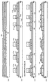
本実施例では、実施例1と異なる作製工程によって液晶表示装置を作製した場合について説明する。説明には図7を用いる。
【0090】
まず、実施例1に従って図2(B)の工程まで行う。但し、本実施例では実施例1の図1(E)の工程を省略する。即ち、ゲート配線(本実施例ではタングステン膜と窒化タングステン膜との積層膜を用いる。)が形成された時点で、活性層にはp型不純物元素のみが添加された状態となる。そして、この状態で実施例1の図2(C)と同様の条件でn型不純物元素を添加し、n型不純物領域(c)701〜710を形成する。(図7(A))
【0091】
次に、公知の技術を用いてサイドウォール711〜716を形成するが、本実施例ではサイドウォールに導電性をもたせる点に特徴がある。即ち、サイドウォールの形成材料としては、サイドウォール自身が電極として機能するような材料を用いる必要がある。本実施例では、n型不純物元素であるリンを成膜時に添加したポリシリコン膜をエッチングすることによりサイドウォール711〜716を形成する。(図7(B))
【0092】
次に、レジストマスク717a〜717cを形成し、この状態で実施例1の図3(A)と同様の条件でn型不純物元素を添加して、n型不純物領域(a)718〜727を形成する。(図7(C))
【0093】
次に、レジストマスク717a〜717cを除去し、新たにレジストマスク728を形成する。そして、サイドウォール711を、フッ素系ガスを用いたドライエッチング法により選択的に除去する。そして、この状態で実施例1の図3(B)と同様の条件でp型不純物元素を添加して、p型不純物領域(a)729、730を形成する。(図7(D))
【0094】
なお、図7(D)においてp型不純物元素を添加する前に、ゲート配線をマスクとして自己整合的にゲート絶縁膜をエッチングしても良い。こうすることで不純物元素を添加する際のドーピング装置の加速電圧を低くすることができるためスループットの向上を図ることができる。
【0095】
この後の工程は、実施例1の図3(C)以降の工程に従えば良い。なお、本実施例の作製工程は実施例1の一部を変更したものであり、その部分以外については、実施例1を準用することができる。また、実施例2に示した液晶表示装置を作製するにあたって、本実施例を実施することができる。
【0096】
[実施例4]
本実施例では、実施例1と異なる作製工程によって液晶表示装置を作製した場合について説明する。説明には図8を用いる。
【0097】
まず、実施例1に従って図2(B)の工程まで行い、各ゲート配線をマスクにしてゲート絶縁膜をエッチングして、ゲート配線の下に残存したゲート絶縁膜801〜806を形成する。エッチングはCHF3ガスを用いたドライエッチング法を用いれば良い。(図8(A))
【0098】
次にレジストマスク807を形成し、この状態で実施例1の図3(B)と同様の条件でp型不純物元素を添加して、p型不純物領域(a)808、809を形成する。(図8(B))
【0099】
次に、不純物を添加するための保護膜810を形成する。保護膜810は100〜500nm(好ましくは150〜200nm)厚の珪素を含む絶縁膜を用いれば良い。本実施例では、150nmの酸化シリコン膜をプラズマCVD法で形成する。(図8(C))
【0100】
次に、図8(C)で形成した保護膜810の上から、実施例1の図3(A)と同様の条件でn型不純物元素を添加して、n型不純物領域(a)811〜818を形成する。(図8(D))
【0101】
なお、p型不純物領域(a)808、809にもn型不純物元素の添加された領域819、820が形成されるが、3倍以上の高い濃度でp型不純物元素が存在するので問題とはならない。この領域819、820は後の活性化工程において、結晶化に用いた触媒元素をゲッタリングする領域として機能する。
【0102】
この後の工程は、実施例1の図3(C)以降の工程に従えば良い。なお、本実施例の作製工程は実施例1の一部を変更したものであり、その部分以外については、実施例1を準用することができる。また、実施例2に示した液晶表示装置を作製するにあたって、本実施例を実施することができる。
【0103】
[実施例5]
本実施例では、実施例1と異なる作製工程によって液晶表示装置を作製した場合について説明する。説明には図9を用いる。
【0104】
まず、実施例1の工程に従って図1(D)の工程まで行ったら、後のゲート電極の形成工程で用いるパターニング用マスクを用いてレジストマスクを形成し、酸素プラズマ処理を行うことで前記レジストマスクを横方向に一定距離だけ後退させる。こうしてレジストマスク901a〜901fを形成する。なお、点線で示したのは、後退する前のレジストマスクの位置である。
【0105】
そして、レジストマスク901a〜901fをマスクとして、実施例1の図1(E)と同様の条件でn型不純物元素を添加する。こうして、n型不純物領域(b)902〜911が形成される。(図9(A))
【0106】
次に、レジストマスク901a〜901fを除去し、ゲート配線の材料となる導電膜(図示せず)を形成する。そして、新たにレジストマスク912a、912bを形成し、導電膜をエッチングして、pチャネル型TFTのゲート配線913を形成する。なお、914に示した導電膜はこのときエッチングしない。
【0107】
さらに、ゲート配線913をマスクとしてドライエッチング法によりゲート絶縁膜119をエッチングし、活性層を露呈させた状態でp型不純物元素の添加を行、p型不純物領域(a)915、916を形成する。添加条件は実施例1の図3(B)の工程に従えば良い。(図9(B))
【0108】
次に、レジストマスク912a、912bを除去し、新たにレジストマスク917a〜917fを形成する。そして、導電膜914をエッチングしてnチャネル型TFTのゲート配線918〜922を形成する。
【0109】
さらに、ゲート配線918〜922をマスクとしてドライエッチング法によりゲート絶縁膜119をエッチングし、図9(C)の状態を得る。
【0110】
そして、実施例4と同様に保護膜923を形成し、実施例1の図3(A)と同様の条件でn型不純物領域(a)924〜931を形成する。(図9(D))
【0111】
なお、p型不純物領域(a)915、916にもn型不純物元素の添加された領域932、933が形成されるが、3倍以上の高い濃度でp型不純物元素が存在するので問題とはならない。この領域932、933は後の活性化工程において、結晶化に用いた触媒元素をゲッタリングする領域として機能する。
【0112】
この後の工程は、実施例1の図3(C)以降の工程に従えば良い。なお、本実施例の作製工程は実施例1の一部を変更したものであり、その部分以外については、実施例1を準用することができる。また、実施例2に示した液晶表示装置を作製するにあたって、本実施例を実施することができる。
【0113】
[実施例6]
実施例5の図9(D)の工程は、保護膜923を用いずにレジストマスクを用いても良い。即ち、図10に示すように、保護膜923の代わりにレジストマスク401a〜401dを形成し、それをマスクとしてn型不純物元素を添加することも可能である。
【0114】
これによりn型不純物領域(a)402〜409が形成され、p型不純物領域に高濃度にn型不純物元素が添加された領域410、411が形成される。なお、本実施例の特徴は、n型不純物領域(b)412、413である。特にnチャネル型不純物領域(b)412は、図4のnチャネル型TFT302のLDD領域207に相当するが、ゲート配線に完全に重なった状態となる。即ち、抵抗成分(LDD領域207のゲート配線に重ならない部分)がないため、より高速動作に適した構造となる。
【0115】
なお、本実施例の作製工程は実施例1(具体的には実施例5)の一部を変更したものであり、その部分以外については、実施例1を準用することができる。また、実施例2に示した液晶表示装置を作製するにあたって、本実施例を実施することができる。
【0116】
[実施例7]
本実施例では、実施例1と異なる作製工程によって液晶表示装置を作製した場合について説明する。説明には図11を用いる。
【0117】
まず、実施例1の工程に従って図2(C)の工程まで行う。次に、レジストマスク501を形成し、実施例1の図3(B)の工程と同様の条件でp型不純物領域(a)502、503を形成する。(図11(A))
【0118】
次に、レジストマスク501を除去し、0.3〜2μm(好ましくは0.5〜1μm)の厚さの珪素を含む絶縁膜504を形成する。この絶縁膜504は実施例1で説明した第1層間絶縁膜に相当する。本実施例では、200nm厚の窒化酸化シリコン膜と800nm厚の酸化シリコン膜とでなる積層膜を用いる。(図11(B))
【0119】
次に、珪素を含む絶縁膜504にコンタクトホール(開孔部)505a〜505iを形成する。そして、実施例1の図3(A)と同様の条件でn型不純物元素の添加工程を行い、n型不純物領域(a)506〜512を形成する。また、このときp型不純物領域(a)502、503にも高濃度にn型不純物元素を領域513、514が形成される。(図11(C))
【0120】
このとき、コンタクトホールを形成する位置がLDD領域の幅を決定する。具体的には、ゲート配線の側面から距離(X)だけ離れた位置までは上記珪素を含む絶縁膜504で覆われた状態としておくように、コンタクトホール505a〜505iを形成する。即ち、第1層間絶縁膜にコンタクトホールを形成するためのパターニング工程はLDD領域(但しゲート配線に重ならないLDD領域)の長さを決定する点に本実施例の特徴がある。
【0121】
また、活性層のうちコンタクトホールの底部に露呈した領域のみがソース領域又はドレイン領域として機能するため、コンタクトホールの径(内径)はできるだけ広く形成することが好ましい。そのためにはコンタクトホールの上面から見た形状が円形であっても良いが、角形であった方が好ましい。
【0122】
なお、本実施例の作製工程は実施例1の一部を変更したものであり、その部分以外については、実施例1を準用することができる。また、実施例2に示した液晶表示装置を作製するにあたって、本実施例を実施することができる。
【0123】
[実施例8]
実施例1の作製工程では、結晶構造を含む半導体膜の形成方法として、結晶化を助長する触媒元素を用いる例を示したが、本実施例では、そのような触媒元素を用いずに熱結晶化またはレーザー結晶化によって結晶構造を含む半導体膜を形成する場合を示す。
【0124】
熱結晶化による場合、非晶質構造を含む半導体膜を形成した後、600〜650℃の温度で15〜24時間の熱処理工程を行えば良い。即ち、600℃を超える温度で熱処理を行うことにより自然核が発生し、結晶化が進行する。
【0125】
また、レーザー結晶化による場合、非晶質構造を含む半導体膜を形成した後、実施例1に示した第1アニール条件でレーザーアニール工程を行えば良い。これにより短時間で結晶構造を含む半導体膜を形成することができる。勿論、レーザーアニールの代わりにランプアニールを行っても良い。
【0126】
また、特願平11−76967号出願明細書の実施例1に記載された技術を用いても良い。同出願明細書の実施例1の作製工程によれば、特異な結晶構造のポリシリコン膜を得ることができる。なお、このポリシリコン膜に関する詳細は、本出願人による特願平10−044659号、特願平10−152316号、特願平10−152308号または特願平10−152305号の出願を参照すれば良い。
【0127】
以上のように、TFTに用いる結晶構造を含む半導体膜は、公知のあらゆる手段を用いて形成することができる。なお、本実施例は実施例1〜7のいずれの構成とも自由に組み合わせることができる。
【0128】
[実施例9]
実施例1の図2(B)の工程、図3(A)の工程又は図3(B)の工程のいずれかの工程において、n型不純物元素又はp型不純物元素を添加する前に、ゲート配線をマスクにしてゲート絶縁膜をエッチングし、除去する工程を行っても良い。
【0129】
ゲート絶縁膜が珪素を含む絶縁膜でなる場合、エッチングガスとしてCHF3を用いたドライエッチング法を用いることが好ましい。こうすることで直接的に活性層に対して不純物元素を添加することになるため、ドーピング時の加速電圧を抑えることができ、スループットの向上を図ることができる。
【0130】
なお、本実施例の構成は、実施例1〜8のいずれの構成とも自由に組み合わせて実施することが可能である。
【0131】
[実施例10]
本発明は半導体基板を用いた従来のMOSFET上に層間絶縁膜を形成し、その上にTFTを形成する際に用いることも可能である。即ち、三次元構造の半導体装置を実現することも可能である。
【0132】
また、反射型液晶表示装置を作製する場合に限り、基板としてSIMOX、Smart−Cut(SOITEC社の登録商標)、ELTRAN(キャノン株式会社の登録商標)などのSOI基板を用いることも可能である。勿論、これらのSOI技術を用いて透明基板上に単結晶半導体薄膜を形成する技術が確立されれば、透過型表示装置に用いることも可能となる。
【0133】
なお、本実施例の構成は、実施例1〜9のいずれの構成とも自由に組み合わせることが可能である。
【0134】
[実施例11]
実施例1〜実施例10に示したTFTの作製プロセスは、アクティブマトリクス型のEL(エレクトロルミネッセンス)表示装置を作製する場合においても適用することができる。
【0135】
通常のEL表示装置では、画素内にスイッチング用のTFTと電流制御用のTFTの二つが形成されるが、図4に示したnチャネル型TFT304がスイッチング用のTFTに適しており、nチャネル型TFT302が電流制御用のTFTに適している。
【0136】
従って、実施例1〜実施例10の作製工程を参照してEL表示装置用のアクティブマトリクス基板を作製し、公知のEL形成技術を用いて、EL表示装置を完成させれば良い。
【0137】
[実施例12]
本願発明の実施によって得られた安価な電気光学装置はパーソナルコンピュータ等のような表示ディスプレイを組み込んだ電子装置(電子製品)全てに部品として組み込むことが可能である。
【0138】
その様な電子装置としては、ビデオカメラ、デジタルスチルカメラ、プロジェクター(リア型またはフロント型)、ゴーグル型ディスプレイ(ヘッドマウントディスプレイ)、カーナビゲーション、パーソナルコンピュータ、携帯情報端末(モバイルコンピュータ、携帯電話または電子書籍等)、記録媒体を備えた画像再生装置(具体的にはコンパクトディスク(CD)、レーザーディスク(LD)又はデジタルビデオディスク(DVD)等の記録媒体を再生し、その画像を表示しうるディスプレイを備えた装置)などが挙げられる。それら半導体装置の例を図12に示す。
【0139】
図12(A)はパーソナルコンピュータであり、本体2001、受像部2002、表示装置2003、キーボード2004等で構成される。本願発明は表示装置2004に用いることができる。
【0140】
図12(B)はビデオカメラであり、本体2101、表示装置2102、音声入力部2103、操作スイッチ2104、バッテリー2105、受像部2106等で構成される。本願発明を表示装置2102に用いることができる。
【0141】
図12(C)はゴーグル型ディスプレイであり、本体2201、表示装置2202、アーム部2203等で構成される。本発明は表示装置2202に用いることができる。
【0142】
図12(D)は記録媒体を備えた画像再生装置(具体的にはDVD再生装置)であり、本体2301、記録媒体(CD、LDまたはDVD等)2302、操作スイッチ2303、表示装置(a)2304、表示装置(b)2305等で構成される。表示装置(a)は主として画像情報を表示し、表示装置(b)は主として文字情報を表示するが、本発明はこれら表示装置(a)、(b)に用いることができる。なお、記録媒体を備えた画像再生装置としては、CD再生装置、ゲーム機器などに本発明を用いることができる。
【0143】
図12(E)はフロント型プロジェクターであり、本体2401、光源、光学系レンズ及び表示装置を含む光学エンジン2402等で構成され、スクリーン2403に画像を表示することができる。本発明は光学エンジン2402に内蔵される表示装置(図示せず)に用いることができる。なお、表示装置は3枚用いる方式でも1枚用いる方式でも良く、透過型表示装置であっても反射型表示装置であっても良い。
【0144】
図12(F)はリア型プロジェクターであり、本体2501、光源、光学系レンズ及び表示装置を含む光学エンジン2402、光源2502、リフレクター2503、2504、スクリーン2505等で構成される。本発明は光学エンジン2502に内蔵される表示装置(図示せず)に用いることができる。なお、表示装置は3枚用いる方式でも1枚用いる方式でも良く、透過型表示装置であっても反射型表示装置であっても良い。
【0145】
なお、本実施例における電気光学装置は実施例1〜11のどのような組み合わせからなる構成を用いて作製されたものであっても良い。
【0146】
【発明の効果】
本願発明を実施することで液晶表示装置やEL表示装置等の電気光学装置の製造工程が簡略化され、製造コストを低減することが可能である。また、そのように低いコストで信頼性の高い電気光学装置を作製することができる。
【0147】
さらに、本願発明の実施によって得られた安価な電気光学装置を搭載することによって電子装置の製造コストも低減することができる。このように本願発明は産業上、非常に有用な技術である。
【図面の簡単な説明】
【図1】 画素部と駆動回路の作製工程を示す図。
【図2】 画素部と駆動回路の作製工程を示す図。
【図3】 画素部と駆動回路の作製工程を示す図。
【図4】 画素部と駆動回路の作製工程を示す図。
【図5】 nチャネル型TFTのLDD構造を示す図。
【図6】 アクティブマトリクス型液晶表示装置の斜視図。
【図7】 画素部と駆動回路の作製工程を示す図。
【図8】 画素部と駆動回路の作製工程を示す図。
【図9】 画素部と駆動回路の作製工程を示す図。
【図10】 画素部と駆動回路の作製工程を示す図。
【図11】 画素部と駆動回路の作製工程を示す図。
【図12】 電子装置の一例を示す図。
【符号の説明】
101 基板
102 下地膜
103 結晶質半導体膜
104 結晶質半導体膜
105〜108 活性層
109 保護膜
110〜113 p型不純物領域(b)が形成された活性層
115〜118 n型不純物領域(b)
119 ゲート絶縁膜
120 導電膜
121a〜121f、149 レジストマスク
122〜124、125a、125、126 ゲート配線
127〜132 n型不純物領域(c)
133〜138 サイドウォール
139〜148 n型不純物領域(a)
150、151 p型不純物領域(a)
152 第1層間絶縁膜
153〜157 チャネル形成領域
158 第2層間絶縁膜
159〜162 ソース配線
163〜166 ドレイン配線
167 パッシベーション膜
168 第3層間絶縁膜
169、170 画素電極[0001]
BACKGROUND OF THE INVENTION
The present invention relates to a method for manufacturing an electro-optical device having an element or a circuit formed of a thin film transistor (hereinafter referred to as TFT) on a substrate having an insulating surface. The present invention also relates to an electronic device including an electro-optical device manufactured using the present invention.
[0002]
[Prior art]
Development of an electro-optical device having an integrated circuit formed of TFTs on a substrate is in progress. Liquid crystal display devices, EL display devices, or contact image sensors are known as representative examples. In particular, a TFT using a polysilicon film (polycrystalline silicon film) as an active layer (hereinafter referred to as poly-Si TFT) has a field effect transfer compared to a TFT using a conventional amorphous silicon film (hereinafter referred to as a-Si TFT). It is attracting attention because of its high degree.
[0003]
As electro-optical devices using poly-Si TFTs, liquid crystal display devices are currently attracting much attention and are already appearing on the market. However, although poly-Si TFTs have high performance, they are more expensive to manufacture than a-Si TFTs. Therefore, reducing the manufacturing cost of poly-Si TFTs has become an important issue in securing the market for liquid crystal display devices using poly-Si TFTs.
[0004]
[Problems to be solved by the invention]
It is an object of the present invention to provide a technique for reducing the manufacturing cost of an electro-optical device using a TFT by reducing the manufacturing cost of the TFT. An object of the present invention is to provide a technique for reducing the manufacturing cost of an electro-optical device, thereby reducing the manufacturing cost of an electronic device including the electro-optical device.
[0005]
[Means for Solving the Problems]
In the present invention, the manufacturing cost is reduced by minimizing the number of patterning steps (photolithography steps) used in the TFT manufacturing process. In order to reduce the patterning process, after forming the gate electrode, a member that can serve as a doping mask is formed on the side wall of the gate electrode without performing a new patterning process. This facilitates forming the LDD region without increasing the patterning process.
[0006]
DETAILED DESCRIPTION OF THE INVENTION
The embodiment of the present invention will be described in detail with reference to the following examples.
[0007]
[Example 1]
An embodiment of the present invention will be described with reference to FIGS. Here, a method for simultaneously manufacturing a pixel portion and a driver circuit provided around the pixel portion will be described. However, in order to simplify the description, regarding the drive circuit, a CMOS circuit which is a basic circuit such as a shift register circuit and a buffer circuit, and an n-channel TFT forming a sampling circuit are illustrated.
[0008]
In FIG. 1A, a glass substrate or a quartz substrate is preferably used for the
[0009]
A base film made of an insulating film containing silicon (referred to as a generic name of a silicon oxide film, a silicon nitride film, or a silicon nitride oxide film in this specification) is formed on the surface of the
[0010]
Note that in this specification, a silicon nitride oxide film is an insulating film expressed by SiOxNy and indicates an insulating film containing silicon, oxygen, and nitrogen at a predetermined ratio. In this embodiment, as the
[0011]
The
[0012]
Next, an amorphous silicon film (not shown) having a thickness of 30 to 120 nm (preferably 50 to 70 nm) is formed on the
[0013]
Then, a
[0014]
Specifically, heat treatment is performed with the catalytic element held on the surface of the amorphous silicon film to change the amorphous silicon film into a polysilicon film. In this embodiment, the technique described in the first embodiment of the publication is used, but the technique described in the second embodiment may be used. In this embodiment, a polysilicon film is used as an example. However, the present invention is not limited to the polysilicon film, and any semiconductor film including a crystalline structure (including a single crystal silicon film) may be used. (Fig. 1 (A))
[0015]
Although depending on the amount of hydrogen contained in the amorphous silicon film, it is preferable that the dehydrogenation treatment is performed by heating at 400 to 550 ° C. for several hours, and the crystallization step is performed with the amount of hydrogen contained being 5 atom% or less. Further, the amorphous silicon film may be formed by other manufacturing methods such as a sputtering method or a vapor deposition method, but it is desirable to sufficiently reduce impurity elements such as oxygen and nitrogen contained in the film.
[0016]
Here, since the base film and the amorphous silicon film can be formed by the same film formation method, they may be formed continuously. After the formation of the base film, it is possible to prevent surface contamination by preventing exposure to the air atmosphere and to reduce variation in characteristics of the manufactured TFT.
[0017]
Next, the
[0018]
Further, instead of laser light, light emitted from a lamp (hereinafter referred to as lamp light) may be irradiated (hereinafter referred to as lamp annealing). As the lamp light, lamp light emitted from a halogen lamp, an infrared lamp, or the like can be used.
[0019]
In addition, the process of performing heat treatment (annealing) with laser light or lamp light in this way is called a light annealing process. Since the light annealing process can be performed at a high temperature in a short time, an effective heat treatment process can be performed with high throughput even when a substrate having low heat resistance such as a glass substrate is used. Of course, since the purpose is annealing, furnace annealing (also referred to as thermal annealing) using an electric furnace can be used instead.
[0020]
In this embodiment, the laser annealing process is performed by processing pulsed excimer laser light into a linear shape. The laser annealing conditions are as follows: XeCl gas is used as the excitation gas, the processing temperature is room temperature, the pulse oscillation frequency is 30 Hz, and the laser energy density is 250 to 500 mJ / cm. 2 (Typically 350-400mJ / cm 2 ).
[0021]
The laser annealing step performed under the above conditions has the effect of completely crystallizing the amorphous region remaining after thermal crystallization and reducing defects in the already crystallized crystalline region. Therefore, this step can also be called a step of improving the crystallinity of the semiconductor film by light annealing or a step of promoting the crystallization of the semiconductor film. Such an effect can also be obtained by optimizing the lamp annealing conditions. In the present specification, such a condition is referred to as a first annealing condition.
[0022]
Next, the
[0023]
Next, a
[0024]
Then, an impurity element imparting p-type conductivity (hereinafter referred to as a p-type impurity element) is added through the
[0025]
Thus 1 × 10 15 ~ 1x10 18 atoms / cm Three (Typically 5 × 10 16 ~ 5x10 17 atoms / cm Three )
[0026]
In this step, boron is also added to the
[0027]
Next, resist
[0028]
The low-
[0029]
Here, phosphine (PH Three ) By mass-separated plasma-excited ion doping method with 1 × 10 phosphorus 18 atoms / cm Three Add at a concentration of Of course, an ion implantation method for performing mass separation may be used. In this step, phosphorus is added to the polysilicon film through the
[0030]
Next, the resist
[0031]
In this embodiment, the laser annealing process is performed by processing pulsed excimer laser light into a linear shape. The laser annealing conditions are as follows: KrF gas is used as the excitation gas, the processing temperature is room temperature, the pulse oscillation frequency is 30 Hz, and the laser energy density is 100 to 300 mJ / cm. 2 (Typically 150-250mJ / cm 2 ).
[0032]
The optical annealing step performed under the above conditions has an effect of activating the added n-type or p-type impurity element and recrystallizing the amorphous semiconductor film when the impurity element is added. . Note that it is preferable that the above conditions ensure atomic arrangement consistency without melting the semiconductor film and activate the impurity element. This step can also be called a step of activating an impurity element imparting n-type or p-type by light annealing, a step of recrystallizing a semiconductor film, or a step of simultaneously performing them. Such an effect can also be obtained by optimizing the lamp annealing conditions. In the present specification, such a condition is referred to as a second annealing condition.
[0033]
By this step, an intrinsic region existing at the boundary between the n-type impurity regions (b) 115 to 118, that is, around the n-type impurity region (b) (the p-type impurity region (b) is also regarded as substantially intrinsic). And the joint part becomes clear. This means that when the TFT is later completed, the LDD region and the channel formation region can form a very good junction.
[0034]
In addition, when activating the impurity element by the laser beam, activation by heat treatment using an electric furnace may be used in combination. When activation by heat treatment is performed, heat treatment at 450 to 650 ° C. (preferably 500 to 550 ° C.) may be performed in consideration of heat resistance of the substrate.
[0035]
Next, a
[0036]
Next, a
[0037]
Here, the
[0038]
In this embodiment, as the
[0039]
In addition, a laminated film of a tungsten nitride film and a tungsten film, a single-layer film including only a tantalum nitride film, and a tungsten silicide film are also suitable. Further, when a structure (polycide structure) in which a silicon film is formed with a thickness of about 2 to 20 nm in the lowermost layer of the gate wiring is improved, the adhesion of the conductive film formed on the silicon film is improved and at the same time Oxidation can be suppressed.
[0040]
In addition, when a metal film is used as the
[0041]
Next, resist
[0042]
Next, an n-type impurity element (phosphorus in this embodiment) is added in a self-aligning manner using the gate wirings 122 to 124, 125a, 125b and the
[0043]
Note that the n-type impurity regions (c) 127 to 132 are already 1 × 10 5 in the channel doping process. 15 ~ 1x10 18 atoms / cm Three In this step, since phosphorus is added at a concentration 5 to 10 times that of boron contained in the p-type impurity region (b), the influence of boron can be ignored.
[0044]
However, strictly speaking, the phosphorus concentration of the portion of the n-type impurity region (b) 115 to 117 that overlaps the gate wiring is 2 × 10. 16 ~ 5x10 19 atoms / cm Three Whereas the portion that does not overlap the gate wiring is 1 × 10 16 ~ 5x10 18 atoms / cm Three The concentration of phosphorus is added, and phosphorus is contained at a slightly higher concentration.
[0045]
Next, the resist
[0046]
Next, an n-type impurity element addition step is performed again using the
[0047]
Next, a resist
[0048]
Note that a part of the
[0049]
Next, after removing the resist
[0050]
In this example, SiH is used by plasma CVD. Four , N 2 O, NH Three As a source gas, a 200 nm thick silicon nitride oxide film (however, the nitrogen concentration is 25 to 50 atomic%) is used. The first
[0051]
Thereafter, a heat treatment step (activation step) is performed to activate the n-type or p-type impurity element added at each concentration. This step can be performed by a furnace annealing method, a laser annealing method, or a rapid thermal annealing method (RTA method). Here, the activation process is performed by furnace annealing. In this heat treatment step, heat treatment is performed in a nitrogen atmosphere at 300 to 650 ° C., preferably 400 to 550 ° C., here 550 ° C. for 4 hours. (Figure 3 (C))
[0052]
At this time, the catalytic element (nickel in this example) used for crystallization of the amorphous silicon film in this example moves in the direction indicated by the arrow, and is formed in the above-described step of FIG. Captured (gettered) in a region containing phosphorus in the concentration. This is a phenomenon caused by the gettering effect of the metal element by phosphorus. As a result, the concentration of the catalyst element in the subsequent
[0053]
On the contrary, in the region that becomes the gettering site of the catalytic element (the region in which the
[0054]
Next, a process of hydrogenating the active layer is performed by performing a heat treatment at 300 to 450 ° C. for 1 to 12 hours in an atmosphere containing 3 to 100% hydrogen. This step is a step of terminating dangling bonds in the semiconductor layer with thermally excited hydrogen. As another means of hydrogenation, plasma hydrogenation (using hydrogen excited by plasma) may be performed.
[0055]
When the activation process is completed, a second
[0056]
As the second
[0057]
Thereafter, contact holes reaching the source region or drain region of each TFT are formed. Here, the fifth patterning step is performed. Then, source wirings 159 to 162 and
[0058]
Although not shown, the
[0059]
Next, the
[0060]
At this time, prior to film formation, H 2 , NH Three It is effective to perform plasma treatment using a gas containing isohydrogen and to perform heat treatment after film formation. Hydrogen excited by this pretreatment is supplied into the first and second interlayer insulating films. By performing heat treatment in this state, the film quality of the
[0061]
Further, a hydrogenation step may be further performed after the
[0062]
Note that an opening may be formed in the
[0063]
Thereafter, a third
[0064]
Here, an acrylic film that is polymerized by heat after being applied to the substrate is used, but a type that is polymerized by light irradiation may be used. Moreover, a negative type resin insulation film is mentioned as a photopolymerization type. In such a type, a portion irradiated with light is polymerized to form a cross-linked structure, so that the resistance to the solution is increased.
[0065]
Further, as a part of the third
[0066]
Next, a contact hole reaching the
[0067]
Note that the
[0068]
In the case of a reflective liquid crystal display device, a metal film may be used as a material for the pixel electrode. In particular, a metal film having a high reflectance is preferable, and an aluminum alloy is preferably used.
[0069]
Thus, a substrate (hereinafter referred to as an active matrix substrate) having a driving circuit and a pixel portion on the same substrate is completed. The number of times of patterning required to complete the process so far is eight, and it can be said that this is a very small number of times as a method for manufacturing an active matrix substrate using poly-Si TFTs.
[0070]
Further, as shown in FIG. 4, when the active matrix substrate is completed, a
[0071]
Further, a light-shielding
[0072]
Then, the active matrix substrate and the counter substrate are bonded with a
[0073]
In FIG. 4, a p-
[0074]
In the p-
[0075]
The n-
[0076]
In the n-channel TFT 303, a
[0077]
Here, the cross-sectional view shown in FIG. 5 is an enlarged view showing a state in which the n-channel TFT 303 shown in FIG. 4 is manufactured up to the step of FIG. As shown here, the
[0078]
In the
[0079]
Further, the
[0080]
According to the manufacturing process of this embodiment, the structure of a TFT for forming a circuit or an element can be optimized according to the performance required by the pixel portion and the driver circuit, and the operation performance and reliability of the semiconductor device can be improved. Specifically, n-channel TFTs have a low LDD region arrangement according to circuit specifications and use different Lov regions or Loff regions. A TFT structure with an emphasis on off-current operation can be realized.
[0081]
For example, in the case of an active matrix liquid crystal display device, the n-
[0082]
The n-channel TFT 303 is suitable for a sampling circuit (sample and hold circuit) that places importance on both hot carrier countermeasures and low off-current operation. That is, hot carrier injection is reduced in the LDD region overlapping with the gate wiring, and the low off-state current is reduced in the LDD region not overlapping with the gate wiring. In addition, the sampling circuit has a structure in which the functions of the source region and the drain region are reversed and the carrier moving direction is changed by 180 °, so that the sampling circuit is line-symmetric with respect to the gate wiring.
[0083]
Further, the n-
[0084]
Further, in this embodiment, a double gate structure is used. However, disposing a high-concentration impurity region (in this case, n-type impurity region (a) 222) between two gate wirings (gate electrodes) is an off-current value. It is very effective in reducing. Note that other multi-gate structures such as a triple gate structure may be used.
[0085]
Of the
[0086]
[Example 2]
In this example, the appearance of the liquid crystal display device manufactured in Example 1 will be described. The perspective view of FIG. 6 is used for the description. The active matrix substrate includes a
[0087]
Further, the drive circuit provided in the periphery is configured based on a CMOS circuit. The gate signal
[0088]
In this specification, the electro-optical device shown in FIG. 6 is called a liquid crystal display device, but the state in which the FPC is attached as shown in FIG. 6 is generally called a liquid crystal module. Therefore, the liquid crystal display device in this embodiment may be called a liquid crystal module.
[0089]
[Example 3]
In this example, a case where a liquid crystal display device is manufactured through a manufacturing process different from that of Example 1 is described. FIG. 7 is used for the description.
[0090]
First, the steps up to the step of FIG. However, in this embodiment, the process of FIG. 1E of Embodiment 1 is omitted. That is, when a gate wiring (a laminated film of a tungsten film and a tungsten nitride film is used in this embodiment) is formed, only the p-type impurity element is added to the active layer. In this state, an n-type impurity element is added under the same conditions as in FIG. 2C of Example 1 to form n-type impurity regions (c) 701 to 710. (Fig. 7 (A))
[0091]
Next, the
[0092]
Next, resist masks 717a to 717c are formed, and in this state, an n-type impurity element is added under the same conditions as in FIG. 3A of Example 1 to form n-type impurity regions (a) 718 to 727. To do. (Fig. 7 (C))
[0093]
Next, the resist masks 717a to 717c are removed, and a new resist
[0094]
Note that before adding the p-type impurity element in FIG. 7D, the gate insulating film may be etched in a self-aligning manner using the gate wiring as a mask. By doing so, the acceleration voltage of the doping apparatus when the impurity element is added can be lowered, so that the throughput can be improved.
[0095]
The subsequent steps may follow the steps after FIG. 3C of the first embodiment. In addition, the manufacturing process of a present Example changes a part of Example 1, and can apply Example 1 mutatis mutandis except the part. In addition, when the liquid crystal display device shown in Embodiment 2 is manufactured, this embodiment can be carried out.
[0096]
[Example 4]
In this example, a case where a liquid crystal display device is manufactured through a manufacturing process different from that of Example 1 is described. FIG. 8 is used for the description.
[0097]
First, the process up to the step of FIG. 2B is performed according to Embodiment 1, and the gate insulating film is etched using each gate wiring as a mask to form
[0098]
Next, a resist
[0099]
Next, a
[0100]
Next, an n-type impurity element is added from above the
[0101]
Note that
[0102]
The subsequent steps may follow the steps after FIG. 3C of the first embodiment. In addition, the manufacturing process of a present Example changes a part of Example 1, and can apply Example 1 mutatis mutandis except the part. In addition, when the liquid crystal display device shown in Embodiment 2 is manufactured, this embodiment can be carried out.
[0103]
[Example 5]
In this example, a case where a liquid crystal display device is manufactured through a manufacturing process different from that of Example 1 is described. FIG. 9 is used for the description.
[0104]
First, after the process up to FIG. 1D is performed according to the process of Example 1, a resist mask is formed using a patterning mask used in a subsequent gate electrode formation process, and the resist mask is subjected to oxygen plasma treatment. Is moved back a certain distance in the horizontal direction. In this way, resist
[0105]
Then, using the resist
[0106]
Next, the resist
[0107]
Further, the
[0108]
Next, the resist
[0109]
Further, the
[0110]
Then, a
[0111]
Note that
[0112]
The subsequent steps may follow the steps after FIG. 3C of the first embodiment. In addition, the manufacturing process of a present Example changes a part of Example 1, and can apply Example 1 mutatis mutandis except the part. In addition, when the liquid crystal display device shown in Embodiment 2 is manufactured, this embodiment can be carried out.
[0113]
[Example 6]
In the step of FIG. 9D of Embodiment 5, a resist mask may be used without using the
[0114]
Thus, n-type impurity regions (a) 402 to 409 are formed, and
[0115]
In addition, the manufacturing process of a present Example changes part of Example 1 (specifically Example 5), Example 1 can be applied mutatis mutandis except the part. In addition, when the liquid crystal display device shown in Embodiment 2 is manufactured, this embodiment can be carried out.
[0116]
[Example 7]
In this example, a case where a liquid crystal display device is manufactured through a manufacturing process different from that of Example 1 is described. FIG. 11 is used for the description.
[0117]
First, the process up to the process of FIG. Next, a resist
[0118]
Next, the resist
[0119]
Next, contact holes (openings) 505a to 505i are formed in the insulating
[0120]
At this time, the position where the contact hole is formed determines the width of the LDD region. Specifically, the
[0121]
In addition, since only the region exposed to the bottom of the contact hole in the active layer functions as the source region or the drain region, it is preferable that the diameter (inner diameter) of the contact hole be as wide as possible. For this purpose, the shape of the contact hole viewed from the top may be circular, but is preferably square.
[0122]
In addition, the manufacturing process of a present Example changes a part of Example 1, and can apply Example 1 mutatis mutandis except the part. In addition, when the liquid crystal display device shown in Embodiment 2 is manufactured, this embodiment can be carried out.
[0123]
[Example 8]
In the manufacturing process of Example 1, an example in which a catalytic element that promotes crystallization is used as a method for forming a semiconductor film including a crystal structure, but in this example, thermal crystallization is performed without using such a catalytic element. A case where a semiconductor film including a crystal structure is formed by crystallization or laser crystallization is shown.
[0124]
In the case of thermal crystallization, a heat treatment step for 15 to 24 hours may be performed at a temperature of 600 to 650 ° C. after forming a semiconductor film including an amorphous structure. That is, by performing heat treatment at a temperature exceeding 600 ° C., natural nuclei are generated and crystallization proceeds.
[0125]
In the case of laser crystallization, a laser annealing process may be performed under the first annealing conditions described in Embodiment 1 after forming a semiconductor film including an amorphous structure. Thus, a semiconductor film including a crystal structure can be formed in a short time. Of course, lamp annealing may be performed instead of laser annealing.
[0126]
Moreover, you may use the technique described in Example 1 of Japanese Patent Application No. 11-76967 application specification. According to the manufacturing process of Example 1 of the same application specification, a polysilicon film having a unique crystal structure can be obtained. For details of this polysilicon film, refer to the applications of Japanese Patent Application No. 10-044659, Japanese Patent Application No. 10-152316, Japanese Patent Application No. 10-152308 or Japanese Patent Application No. 10-152305 filed by the present applicant. It ’s fine.
[0127]
As described above, a semiconductor film including a crystal structure used for a TFT can be formed using any known means. In addition, a present Example can be freely combined with any structure of Examples 1-7.
[0128]
[Example 9]
In any one of the steps of FIG. 2B, FIG. 3A, or FIG. 3B of the first embodiment, the gate is added before the n-type impurity element or the p-type impurity element is added. A step of etching and removing the gate insulating film using the wiring as a mask may be performed.
[0129]
When the gate insulating film is an insulating film containing silicon, CHF is used as an etching gas. Three It is preferable to use a dry etching method using By doing so, the impurity element is directly added to the active layer, so that the acceleration voltage during doping can be suppressed and the throughput can be improved.
[0130]
In addition, the structure of a present Example can be implemented in combination with any structure of Examples 1-8 freely.
[0131]
[Example 10]
The present invention can also be used when an interlayer insulating film is formed on a conventional MOSFET using a semiconductor substrate and a TFT is formed thereon. That is, it is possible to realize a three-dimensional semiconductor device.
[0132]
Further, only when a reflective liquid crystal display device is manufactured, an SOI substrate such as SIMOX, Smart-Cut (registered trademark of SOITEC), ELTRAN (registered trademark of Canon Inc.), or the like can be used as a substrate. Of course, if a technique for forming a single crystal semiconductor thin film on a transparent substrate using these SOI techniques is established, it can be used for a transmissive display device.
[0133]
In addition, the structure of a present Example can be freely combined with any structure of Examples 1-9.
[0134]
[Example 11]
The manufacturing process of the TFT shown in Embodiments 1 to 10 can be applied to the case of manufacturing an active matrix EL (electroluminescence) display device.
[0135]
In an ordinary EL display device, a switching TFT and a current control TFT are formed in a pixel. The n-
[0136]
Therefore, an active matrix substrate for an EL display device may be manufactured with reference to the manufacturing steps of Embodiments 1 to 10, and the EL display device may be completed using a known EL formation technique.
[0137]
[Example 12]
An inexpensive electro-optical device obtained by carrying out the present invention can be incorporated as a part in any electronic device (electronic product) incorporating a display such as a personal computer.
[0138]
Such electronic devices include video cameras, digital still cameras, projectors (rear type or front type), goggle type displays (head mounted displays), car navigation systems, personal computers, personal digital assistants (mobile computers, mobile phones or electronic devices). A display capable of playing back a recording medium such as a book, etc., and a recording medium (specifically, a compact disc (CD), laser disc (LD), digital video disc (DVD), etc.) And the like). Examples of these semiconductor devices are shown in FIGS.
[0139]
FIG. 12A illustrates a personal computer, which includes a main body 2001, an image receiving portion 2002, a display device 2003, a
[0140]
FIG. 12B illustrates a video camera which includes a main body 2101, a display device 2102, an
[0141]
FIG. 12C illustrates a goggle type display which includes a
[0142]
FIG. 12D shows an image reproducing device (specifically, a DVD reproducing device) provided with a recording medium, which includes a main body 2301, a recording medium (CD, LD, DVD, etc.) 2302, an
[0143]
FIG. 12E illustrates a front type projector, which includes a
[0144]
FIG. 12F illustrates a rear projector, which includes a main body 2501, an
[0145]
Note that the electro-optical device according to the present embodiment may be manufactured using a configuration including any combination of the first to eleventh embodiments.
[0146]
【The invention's effect】
By implementing the present invention, the manufacturing process of an electro-optical device such as a liquid crystal display device or an EL display device can be simplified, and the manufacturing cost can be reduced. In addition, a highly reliable electro-optical device can be manufactured at such a low cost.
[0147]
Furthermore, the manufacturing cost of the electronic device can be reduced by mounting an inexpensive electro-optical device obtained by implementing the present invention. Thus, the present invention is a very useful technology in industry.
[Brief description of the drawings]
FIGS. 1A and 1B illustrate a manufacturing process of a pixel portion and a driver circuit. FIGS.
FIGS. 2A and 2B illustrate a manufacturing process of a pixel portion and a driver circuit. FIGS.
FIGS. 3A and 3B are diagrams illustrating a manufacturing process of a pixel portion and a driver circuit. FIGS.
FIGS. 4A and 4B illustrate a manufacturing process of a pixel portion and a driver circuit. FIGS.
FIG. 5 is a diagram showing an LDD structure of an n-channel TFT.
FIG. 6 is a perspective view of an active matrix liquid crystal display device.
FIGS. 7A to 7C illustrate a manufacturing process of a pixel portion and a driver circuit. FIGS.
FIGS. 8A and 8B illustrate a manufacturing process of a pixel portion and a driver circuit. FIGS.
FIGS. 9A and 9B illustrate a manufacturing process of a pixel portion and a driver circuit. FIGS.
FIGS. 10A and 10B illustrate a manufacturing process of a pixel portion and a driver circuit. FIGS.
FIG. 11 illustrates a manufacturing process of a pixel portion and a driver circuit.
FIG. 12 illustrates an example of an electronic device.
[Explanation of symbols]
101 substrate
102 Base film
103 crystalline semiconductor film
104 crystalline semiconductor film
105-108 active layer
109 Protective film
110-113 Active layer in which p-type impurity region (b) is formed
115-118 n-type impurity region (b)
119 Gate insulation film
120 conductive film
121a to 121f, 149 resist mask
122-124, 125a, 125, 126 Gate wiring
127-132 n-type impurity region (c)
133-138 sidewall
139-148 n-type impurity region (a)
150, 151 p-type impurity region (a)
152 First interlayer insulating film
153 to 157 channel formation region
158 Second interlayer insulating film
159-162 Source wiring
163 to 166 Drain wiring
167 Passivation film
168 Third interlayer insulating film
169, 170 Pixel electrode
Claims (9)
前記半導体膜から島状の半導体膜でなる活性層を形成し、
前記活性層上に第1のレジストマスクを形成し、
前記第1のレジストマスクをマスクとして前記活性層の一部にn型不純物元素を選択的に添加して第1のn型不純物領域を形成し、
前記第1のレジストマスクを除去し、
前記活性層上にゲート絶縁膜を形成し、
前記ゲート絶縁膜上に導電膜を形成し、
前記導電膜上に第2のレジストマスクを形成し、
前記第2のレジストマスクを用いて前記導電膜をエッチングすることにより、前記第1のn型不純物領域の一部と重なるゲート配線を形成し、
前記ゲート配線をマスクとして前記活性層にn型不純物元素を添加して第2のn型不純物領域を形成し、
前記第2のレジストマスクを除去し、
前記ゲート配線の側壁にサイドウォールを形成し、
前記ゲート配線及び前記サイドウォールをマスクとして前記活性層にn型不純物元素を添加して第3のn型不純物領域を形成することを特徴とする電気光学装置の作製方法。Forming a semiconductor film on the substrate;
An active layer made of an island-shaped semiconductor film is formed from the semiconductor film,
Forming a first resist mask on the active layer;
Using the first resist mask as a mask, an n-type impurity element is selectively added to a part of the active layer to form a first n-type impurity region;
Removing the first resist mask;
Forming a gate insulating film on the active layer;
Forming a conductive film on the gate insulating film;
Forming a second resist mask on the conductive film;
By etching the conductive film using the second resist mask to form a gate wiring overlaps a portion of the first n-type impurity regions,
Using the gate wiring as a mask, an n-type impurity element is added to the active layer to form a second n-type impurity region,
Removing the second resist mask;
Forming a sidewall on the side wall of the gate wiring;
A method for manufacturing an electro-optical device, wherein a third n-type impurity region is formed by adding an n-type impurity element to the active layer using the gate wiring and the sidewall as a mask.
前記半導体膜から島状の半導体膜でなる第1の活性層及び第2の活性層を形成し、
前記第1の活性層及び前記第2の活性層上に第1のレジストマスクを形成し、
前記第1のレジストマスクをマスクとして前記第1の活性層の一部にn型不純物元素を選択的に添加して第1のn型不純物領域を形成し、
前記第1のレジストマスクを除去し、
前記第1の活性層及び前記第2の活性層上にゲート絶縁膜を形成し、
前記ゲート絶縁膜上に導電膜を形成し、
前記導電膜上に第2のレジストマスクを形成し、
前記第2のレジストマスクを用いて前記導電膜をエッチングすることにより、前記第1のn型不純物領域の一部と重なる第1のゲート配線及び前記第2の活性層と重なる第2のゲート配線を形成し、
前記第1のゲート配線をマスクとして前記第1の活性層にn型不純物元素を添加して第2のn型不純物領域を形成し、
前記第2のレジストマスクを除去し、
前記第1のゲート配線の側壁及び前記第2のゲート配線の側壁にサイドウォールを形成し、
前記第1のゲート配線及び前記第1のゲート配線の側壁に形成された前記サイドウォールをマスクとして前記第1の活性層にn型不純物元素を添加して第3のn型不純物領域を形成し、
前記第2のゲート配線の側壁に形成された前記サイドウォールを除去し、
前記第2のゲート配線をマスクとして前記第2の活性層にp型不純物元素を添加してp型不純物領域を形成することを特徴とする電気光学装置の作製方法。Forming a semiconductor film on the substrate;
Forming a first active layer and a second active layer made of an island-shaped semiconductor film from the semiconductor film;
Forming a first resist mask on the first active layer and the second active layer;
Using the first resist mask as a mask, an n-type impurity element is selectively added to a part of the first active layer to form a first n-type impurity region;
Removing the first resist mask;
Forming a gate insulating film on the first active layer and the second active layer;
Forming a conductive film on the gate insulating film;
Forming a second resist mask on the conductive film;
Wherein by etching the conductive film using the second resist mask, the first of the first overlapped part of the n-type impurity region of the gate wiring and the second gate lines overlapping the second active layer Form the
An n-type impurity element is added to the first active layer using the first gate wiring as a mask to form a second n-type impurity region;
Removing the second resist mask;
Forming sidewalls on the sidewalls of the first gate wiring and the second gate wiring;
Wherein the n-type impurity element third n-type impurity region formed in the addition to the first active layer a first said side wall formed on the side wall of the gate line and the first gate wiring as a mask ,
Removing the said sidewall formed on the side wall of the second gate line,
A method of manufacturing an electro-optical device, wherein a p-type impurity region is formed by adding a p-type impurity element to the second active layer using the second gate wiring as a mask.
前記サイドウォールはポリシリコン膜で形成されることを特徴とする電気光学装置の作製方法。In claim 1 or claim 2,
The method of manufacturing an electro-optical device, wherein the sidewall is formed of a polysilicon film.
前記半導体膜から島状の半導体膜でなる活性層を形成し、
前記活性層上にパターニング用マスクを用いて第1のレジストマスクを形成し、
前記第1のレジストマスクを酸素プラズマ処理することにより、前記第1のレジストマスクの幅を減少させ、
幅を減少させた前記第1のレジストマスクをマスクとして前記活性層にn型不純物元素を添加して第1のn型不純物領域を形成し、
前記第1のレジストマスクを除去し、
前記活性層上にゲート絶縁膜を形成し、
前記ゲート絶縁膜上に導電膜を形成し、
前記導電膜上に前記パターニング用マスクを用いて第2のレジストマスクを形成し、
前記第2のレジストマスクを用いて前記導電膜をエッチングすることにより、ゲート配線を形成し、
前記第2のレジストマスクを除去し、
前記ゲート配線及び前記活性層を覆うように保護膜を形成し、
前記ゲート配線をマスクとして前記保護膜を通して前記活性層にn型不純物元素を添加して第2のn型不純物領域を形成することを特徴とする電気光学装置の作製方法。Forming a semiconductor film on the substrate;
An active layer made of an island-shaped semiconductor film is formed from the semiconductor film,
Forming a first resist mask on the active layer using a patterning mask;
By oxygen plasma treatment the first resist mask, it reduces the width of the first resist mask,
Using the first resist mask having a reduced width as a mask, an n-type impurity element is added to the active layer to form a first n-type impurity region,
Removing the first resist mask;
Forming a gate insulating film on the active layer;
Forming a conductive film on the gate insulating film;
Forming a second resist mask on the conductive film using the patterning mask;
By etching the conductive film using the second resist mask to form a gate wiring,
Removing the second resist mask;
Forming a protective film to cover the gate wiring and the active layer;
A method of manufacturing an electro-optical device, wherein a second n-type impurity region is formed by adding an n-type impurity element to the active layer through the protective film using the gate wiring as a mask.
前記保護膜は珪素を含む絶縁膜であり、当該絶縁膜の膜厚は100nm〜500nmであることを特徴とする電気光学装置の作製方法。In claim 4,
The protective film is an insulating film containing silicon, and the thickness of the insulating film is 100 nm to 500 nm.
前記ゲート配線をマスクとして前記ゲート絶縁膜を除去することを特徴とする電気光学装置の作製方法。In claim 4 or claim 5,
A method for manufacturing an electro-optical device, wherein the gate insulating film is removed using the gate wiring as a mask.
前記第3のn型不純物領域には、1×10²⁰atoms/cm3〜1×1021atoms/cm3のn型不純物元素が含まれていることを特徴とする電気光学装置の作製方法。In any one of Claims 1 thru | or 3,
The method for manufacturing an electro-optical device, wherein the third n-type impurity region contains an n-type impurity element of 1 × 10 20 atoms / cm 3 to 1 × 10 21 atoms / cm 3 .
前記第1のn型不純物領域には、2×10¹⁶atoms/cm3〜5×1019atoms/cm3のn型不純物元素が含まれていることを特徴とする電気光学装置の作製方法。In any one of Claims 1 thru | or 7 ,
The method for manufacturing an electro-optical device, wherein the first n-type impurity region contains an n-type impurity element of 2 × 10 16 atoms / cm 3 to 5 × 10 19 atoms / cm 3 .
前記第2のn型不純物領域には、1×10¹⁶atoms/cm3〜5×1018atoms/cm3のn型不純物元素が含まれていることを特徴とする電気光学装置の作製方法。In any one of Claims 1 thru | or 8 ,
The method for manufacturing an electro-optical device, wherein the second n-type impurity region contains an n-type impurity element of 1 × 10 16 atoms / cm 3 to 5 × 10 18 atoms / cm 3 .
Priority Applications (1)
| Application Number | Priority Date | Filing Date | Title |
|---|---|---|---|
| JP19108199A JP4372896B2 (en) | 1999-07-05 | 1999-07-05 | Method for manufacturing electro-optical device |
Applications Claiming Priority (1)
| Application Number | Priority Date | Filing Date | Title |
|---|---|---|---|
| JP19108199A JP4372896B2 (en) | 1999-07-05 | 1999-07-05 | Method for manufacturing electro-optical device |
Publications (3)
| Publication Number | Publication Date |
|---|---|
| JP2001024197A JP2001024197A (en) | 2001-01-26 |
| JP2001024197A5 JP2001024197A5 (en) | 2006-08-24 |
| JP4372896B2 true JP4372896B2 (en) | 2009-11-25 |
Family
ID=16268555
Family Applications (1)
| Application Number | Title | Priority Date | Filing Date |
|---|---|---|---|
| JP19108199A Expired - Fee Related JP4372896B2 (en) | 1999-07-05 | 1999-07-05 | Method for manufacturing electro-optical device |
Country Status (1)
| Country | Link |
|---|---|
| JP (1) | JP4372896B2 (en) |
Families Citing this family (5)
| Publication number | Priority date | Publication date | Assignee | Title |
|---|---|---|---|---|
| KR100623230B1 (en) * | 2003-11-29 | 2006-09-18 | 삼성에스디아이 주식회사 | Method of fabricating Thin Film Transistor |
| KR102092842B1 (en) * | 2013-08-07 | 2020-04-16 | 삼성디스플레이 주식회사 | Display panel and method of manufacturing the same |
| KR102158365B1 (en) * | 2020-03-18 | 2020-09-22 | 삼성디스플레이 주식회사 | Display panel and method of manufacturing the same |
| KR102402739B1 (en) * | 2020-09-15 | 2022-05-31 | 삼성디스플레이 주식회사 | Display panel and method of manufacturing the same |
| KR102199496B1 (en) * | 2020-09-15 | 2021-01-07 | 삼성디스플레이 주식회사 | Display panel and method of manufacturing the same |
-
1999
- 1999-07-05 JP JP19108199A patent/JP4372896B2/en not_active Expired - Fee Related
Also Published As
| Publication number | Publication date |
|---|---|
| JP2001024197A (en) | 2001-01-26 |
Similar Documents
| Publication | Publication Date | Title |
|---|---|---|
| US6359320B1 (en) | Thin-film transistor with lightly-doped drain | |
| KR100659921B1 (en) | Semiconductor device and the fabricating method therefor | |
| US6780687B2 (en) | Method of manufacturing a semiconductor device having a heat absorbing layer | |
| US6777254B1 (en) | Semiconductor device and fabrication method thereof | |
| JP4307635B2 (en) | Method for manufacturing semiconductor device | |
| US6680488B2 (en) | Semiconductor device | |
| KR20010020826A (en) | Semiconductor Device and Method for Its Fabrication | |
| JP4094179B2 (en) | Method for manufacturing semiconductor device | |
| JP4563499B2 (en) | Method for manufacturing semiconductor device | |
| JP4372896B2 (en) | Method for manufacturing electro-optical device | |
| JP2000183360A (en) | Semiconductor device having semiconductor circuit made of semiconductor element and manufacture thereof | |
| JP4494451B2 (en) | Method for manufacturing semiconductor device | |
| JP4437511B2 (en) | Method for manufacturing electro-optical device | |
| JP4245739B2 (en) | Method for manufacturing electro-optical device | |
| JP2001085320A (en) | Aligner, exposure method and nethod for manufacturing semiconductor device | |
| JP4656685B2 (en) | Semiconductor device | |
| JP4080168B2 (en) | Method for manufacturing semiconductor device | |
| JP3907898B2 (en) | Method for manufacturing semiconductor device | |
| JP2000150903A (en) | Semiconductor device provided with semiconductor circuit consisting of semiconductor element and manufacture thereof | |
| JPH10214975A (en) | Semiconductor device and fabrication thereof |
Legal Events
| Date | Code | Title | Description |
|---|---|---|---|
| A521 | Written amendment |
Free format text: JAPANESE INTERMEDIATE CODE: A523 Effective date: 20060630 |
|
| A621 | Written request for application examination |
Free format text: JAPANESE INTERMEDIATE CODE: A621 Effective date: 20060630 |
|
| A131 | Notification of reasons for refusal |
Free format text: JAPANESE INTERMEDIATE CODE: A131 Effective date: 20081216 |
|
| A977 | Report on retrieval |
Free format text: JAPANESE INTERMEDIATE CODE: A971007 Effective date: 20081218 |
|
| A521 | Written amendment |
Free format text: JAPANESE INTERMEDIATE CODE: A523 Effective date: 20090206 |
|
| TRDD | Decision of grant or rejection written | ||
| A01 | Written decision to grant a patent or to grant a registration (utility model) |
Free format text: JAPANESE INTERMEDIATE CODE: A01 Effective date: 20090901 |
|
| A01 | Written decision to grant a patent or to grant a registration (utility model) |
Free format text: JAPANESE INTERMEDIATE CODE: A01 |
|
| A61 | First payment of annual fees (during grant procedure) |
Free format text: JAPANESE INTERMEDIATE CODE: A61 Effective date: 20090903 |
|
| FPAY | Renewal fee payment (event date is renewal date of database) |
Free format text: PAYMENT UNTIL: 20120911 Year of fee payment: 3 |
|
| R150 | Certificate of patent or registration of utility model |
Free format text: JAPANESE INTERMEDIATE CODE: R150 |
|
| FPAY | Renewal fee payment (event date is renewal date of database) |
Free format text: PAYMENT UNTIL: 20120911 Year of fee payment: 3 |
|
| FPAY | Renewal fee payment (event date is renewal date of database) |
Free format text: PAYMENT UNTIL: 20120911 Year of fee payment: 3 |
|
| FPAY | Renewal fee payment (event date is renewal date of database) |
Free format text: PAYMENT UNTIL: 20130911 Year of fee payment: 4 |
|
| R250 | Receipt of annual fees |
Free format text: JAPANESE INTERMEDIATE CODE: R250 |
|
| R250 | Receipt of annual fees |
Free format text: JAPANESE INTERMEDIATE CODE: R250 |
|
| R250 | Receipt of annual fees |
Free format text: JAPANESE INTERMEDIATE CODE: R250 |
|
| R250 | Receipt of annual fees |
Free format text: JAPANESE INTERMEDIATE CODE: R250 |
|
| R250 | Receipt of annual fees |
Free format text: JAPANESE INTERMEDIATE CODE: R250 |
|
| LAPS | Cancellation because of no payment of annual fees |