JP4369753B2 - Composite structure ship - Google Patents
Composite structure ship Download PDFInfo
- Publication number
- JP4369753B2 JP4369753B2 JP2003536095A JP2003536095A JP4369753B2 JP 4369753 B2 JP4369753 B2 JP 4369753B2 JP 2003536095 A JP2003536095 A JP 2003536095A JP 2003536095 A JP2003536095 A JP 2003536095A JP 4369753 B2 JP4369753 B2 JP 4369753B2
- Authority
- JP
- Japan
- Prior art keywords
- ship
- ship according
- interior
- walls
- members
- Prior art date
- Legal status (The legal status is an assumption and is not a legal conclusion. Google has not performed a legal analysis and makes no representation as to the accuracy of the status listed.)
- Expired - Fee Related
Links
Images


Classifications
-
- B—PERFORMING OPERATIONS; TRANSPORTING
- B63—SHIPS OR OTHER WATERBORNE VESSELS; RELATED EQUIPMENT
- B63B—SHIPS OR OTHER WATERBORNE VESSELS; EQUIPMENT FOR SHIPPING
- B63B3/00—Hulls characterised by their structure or component parts
- B63B3/14—Hull parts
- B63B3/26—Frames
- B63B3/36—Combined frame systems
-
- B—PERFORMING OPERATIONS; TRANSPORTING
- B63—SHIPS OR OTHER WATERBORNE VESSELS; RELATED EQUIPMENT
- B63B—SHIPS OR OTHER WATERBORNE VESSELS; EQUIPMENT FOR SHIPPING
- B63B29/00—Accommodation for crew or passengers not otherwise provided for
- B63B29/02—Cabins or other living spaces; Construction or arrangement thereof
-
- B—PERFORMING OPERATIONS; TRANSPORTING
- B63—SHIPS OR OTHER WATERBORNE VESSELS; RELATED EQUIPMENT
- B63B—SHIPS OR OTHER WATERBORNE VESSELS; EQUIPMENT FOR SHIPPING
- B63B3/00—Hulls characterised by their structure or component parts
- B63B3/14—Hull parts
- B63B3/48—Decks
-
- B—PERFORMING OPERATIONS; TRANSPORTING
- B63—SHIPS OR OTHER WATERBORNE VESSELS; RELATED EQUIPMENT
- B63B—SHIPS OR OTHER WATERBORNE VESSELS; EQUIPMENT FOR SHIPPING
- B63B5/00—Hulls characterised by their construction of non-metallic material
- B63B5/02—Hulls characterised by their construction of non-metallic material made predominantly of wood
- B63B5/04—Carcasses
-
- B—PERFORMING OPERATIONS; TRANSPORTING
- B63—SHIPS OR OTHER WATERBORNE VESSELS; RELATED EQUIPMENT
- B63B—SHIPS OR OTHER WATERBORNE VESSELS; EQUIPMENT FOR SHIPPING
- B63B5/00—Hulls characterised by their construction of non-metallic material
- B63B5/14—Hulls characterised by their construction of non-metallic material made predominantly of concrete, e.g. reinforced
-
- B—PERFORMING OPERATIONS; TRANSPORTING
- B63—SHIPS OR OTHER WATERBORNE VESSELS; RELATED EQUIPMENT
- B63B—SHIPS OR OTHER WATERBORNE VESSELS; EQUIPMENT FOR SHIPPING
- B63B3/00—Hulls characterised by their structure or component parts
- B63B3/14—Hull parts
- B63B2003/145—Frameworks, i.e. load bearing assemblies of trusses and girders interconnected at nodal points
Abstract
Description
本発明は、その支持構造が立体骨組構造体から構成され、(複数の)腹材が、下弦部及び上弦部と曲げ−、剪断−及びねじれ抵抗的に互いに結合されると共に、該下弦部が(船底部の)複数の部材又は船底部全体から構成される形式の船舶に関する。これとは独立して、複数の支材、複数の引張部材及び複数のフィリグラン形成(filigranen)デッキ支持部材から形成されると共に内装構造荷重を一次的立体骨組構造体に導入するスケルトン構造の2次的支持構造を有するよう構成された、全体としての(ひとまとまりの)内装構造が存在する。内装構造全体は、スケルトン構造の骨組構造体の全体的な支持機能から実質的に解放(免除)され、自重による荷重、積荷(航行)荷重(Verkehrslasten)及び動的負荷による荷重しか実質的に受けない。
In the present invention, the supporting structure is constituted by a three-dimensional frame structure, and the abdomen (s) are coupled to each other in a bending-, shear- and torsion-resistant manner with the lower chord and upper chord, and the lower chord is The present invention relates to a type of ship composed of a plurality of members (of the ship bottom) or the entire ship bottom. Independently of this, a
ドイツ特許DE 36 18 851 C2(特許文献1)には、複数のデッキ及び複数の壁を支持する複数の支持部材からなる構造体を有する平面状の浮動体を設けた浮動構造体が示されている。これは船舶ではないので、特許文献1に提案の支持構造は、下弦部及び上弦部を有する立体骨組構造体として構成されてない。同様に、1次的支持構造と2次的内装構造との間で系統的(システマチック)な分離を行うという思想は、開示されてない。
German patent DE 36 18 851 C2 (Patent Document 1) shows a floating structure provided with a planar floating body having a structure comprising a plurality of decks and a plurality of support members for supporting a plurality of walls. Yes. Since this is not a ship, the support structure proposed in
複数の外部船内壁の範囲に対角線方向の補助結合部材を有する支持シェルから構築された船体構造が、1927年5月3日のドイツ特許公報443 599(特許文献2)から公知である。しかしながら、立体骨組構造体において複数の腹材のみが下弦部及び上弦部と曲げ−、剪断−及びねじれ抵抗的に互いに結合するという思想は、特許文献2から見出すことはできない。
A hull structure constructed from a support shell having a diagonal auxiliary coupling member in the range of a plurality of external ship inner walls is known from German patent publication 443 599 (patent document 2) of May 3, 1927. However, the idea that only a plurality of abdominal members are coupled to each other in a bending-, shearing- and torsion-resistant manner in the three-dimensional frame structure cannot be found from
本発明は、上記の先行技術を出発点とした下記の2つの課題を有する:
第1の課題は、船体構造の積載量、剛性(強度)従って稼動寿命を増大することである。
本発明の第2の課題は、内装構造において、軽量構造を使用することにより、著しい重量軽減を達成し、かくして、建造から保守を経て解体に至るまでの稼動サイクル全体に対する経費節減を可能にすることである。
The present invention has the following two problems starting from the above prior art:
The first problem is to increase the load capacity, rigidity (strength) and thus the service life of the hull structure.
The second object of the present invention is to achieve a significant weight reduction by using a lightweight structure in the interior structure, thus enabling cost savings for the entire operating cycle from construction through maintenance to dismantling. That is.
上記2つの課題は、本発明の一視点によれば、請求項1の特徴によって解決される。即ち、少なくとも支持構造、内装構造及び流体力学的観点に応じて形成される船底部を有する船体構造を有する船舶において、前記支持構造は、1つの上弦部、1つの下弦部及び複数の腹材を有する立体骨組構造体を有し、前記複数の腹材が前記上弦部と前記下弦部とを離隔状態に保持しかつ曲げ−、剪断−及びねじり抵抗的に互いに結合することにより、前記立体骨組構造体が船体の全体的な支持機能を有し、前記内装構造は船体の全体的な支持機能から実質的に解放されて配されること、及び前記内装構造は、複数の長手壁、複数の横手壁、複数の船内壁及び複数のデッキを有することを特徴とする(形態1・基本構成)。
The above two problems are solved by the features of
本発明の独立請求項1により、上記課題に対応する効果が達成される。即ち、本発明の船舶は、船体構造の積載量、剛性(強度)従って稼動寿命が増大され、更に、内装構造において、軽量構造を使用することにより、著しい重量軽減を達成し、かくして、建造から保守を経て解体に至るまでの稼動サイクル全体に対する経費節減が可能となっている。According to the
更に、各従属請求項により、付加的な効果がそれぞれ達成される。 Furthermore, each additional claim achieves an additional effect.
以下に、本発明の好ましい実施の形態を、上記基本構成を形態1として示すが、これらは従属請求項の対象でもある。
(形態2) 上記形態1の船舶において、前記複数の腹材は、前記上弦部と前記下弦部とを離隔状態に保持し、かつ曲げ−、剪断−及びねじり抵抗的に互いに結合することが好ましい。
(形態3) 上記形態1又は2の船舶において、前記内装構造は、複数の長手壁、複数の横手壁、複数の船内壁及び複数のデッキを有することが好ましい。
(形態4) 上記形態1〜3の船舶において、複数の貨物室を有することが好ましい。
(形態5) 上記形態1〜4の船舶において、前記立体骨組構造体は、複弦材横断面を有することが好ましい。
(形態6) 上記形態5の船舶において、前記立体骨組構造体は、矩形横断面を有することが好ましい。
(形態7) 上記形態5又は6の船舶において、前記立体骨組構造体は、十字状横断面を有することが好ましい。
(形態8) 上記形態5〜7の船舶において、前記立体骨組構造体は、組立てられた筒状横断面を有することが好ましい。
(形態9) 上記形態1〜8の船舶において、前記立体骨組構造体は、少なくとも1つの補強デッキを有することが好ましい。
(形態10) 上記形態9の船舶において、前記補強デッキは、水平ラーメンフレーム板状構造を有することが好ましい。
(形態11) 上記形態9又は10の船舶において、前記補強デッキは、水平トラスフレーム板状構造を有することが好ましい。
(形態12) 上記形態1〜11の船舶において、前記立体骨組構造体は、前記船底部の流体力学的形態に対し多角形の配列形状(輪郭)に(polygonzugartig)適合されることが好ましい。
(形態13) 上記形態1〜12の船舶において、前記立体骨組構造体の上弦部は、弦部材、水平ラーメンフレーム板状構造、水平トラスフレーム板状構造、リブプレート、又は鋼及び/又はコンクリート複合プレートを有することが好ましい。
(形態14) 上記形態1〜13の船舶において、前記立体骨組構造体の下弦部は、前記船底部の外被構造、二重底、鋼及びコンクリートからなる複合シェル、及び/又は複数の長手隔壁、複数の横手隔壁及び複数の中間デッキをすべて含む前記船底部全体を有することが好ましい。
(形態15) 上記形態1〜14の船舶において、前記複数の腹材は、長手方向に形成されるラーメンフレーム板状構造及び/又は長手方向に形成されるトラスフレーム板状構造の種類に応じて組立てられることが好ましい。
(形態16) 上記形態15の船舶において、前記複数の腹材は、キール線において、前記船底部を前記上弦部と直接的に結合することが好ましい。
(形態17) 上記形態15又は16の船舶において、前記複数の腹材は、キール線の左右において又は外部船内壁の面において、前記船底部を前記上弦部と直接的に結合することが好ましい。
(形態18) 上記形態1〜17の船舶において、前記複数の腹材は、複数の節点結合部を介して、枢動可能に又は曲げ抵抗的に前記上弦部及び前記下弦部に結合されることが好ましい。
(形態19) 上記形態1〜18の船舶において、前記複数の腹材は、箱形横断面、円環プロフィル(Rundhohlprofil)横断面及び/又は円管横断面を有する複数の棒状支持部材を有することが好ましい。
(形態20) 上記形態19の船舶において、前記複数の棒状支持部材は、進入開口(保守等のために人間、ロボット等の物体が通り抜け可能な開口)を有する内部横手隔壁を有することが好ましい。
(形態21) 上記形態1〜20の船舶において、前記複数の腹材は、複数の引張部材のみを有することが好ましい。
(形態22) 上記形態1〜21の船舶において、前記内装構造は、複数の内装構造支材と複数の内装構造引張部材と複数の内装構造デッキとを有するスケルトン構造の2次的支持フレームワークを有することが好ましい。
(形態23) 上記形態22の船舶において、前記複数の内装構造支材は、前記二重底上に設置されると共に、前記複数の内装構造引張部材は、前記上弦部に懸設されることが好ましい。
(形態24) 上記形態1〜23の船舶において、前記内装構造は、前記複数の外部船内壁及び/又は前記複数の長手壁・横手壁の部材(複数)を形成する複数の平面状要素を有することが好ましい。
(形態25) 上記形態1〜24の船舶において、長手軸線が航行方向へ延在し、かつ前記内装構造が居住区、アトリウム、照明開口及び/又は同様の機能空間の種類に応じた客船の空間プログラムを含むと共に、該空間プログラムの各要素は、該長手軸線に対する直交方向に船体を区分けすることが好ましい。
(形態26) 上記形態1〜25の船舶において、前記内装構造は、全方向から照明可能であり、かつ複数の階段及び/又は複数のエレベータを有する独立した内部開発システム(Erschliessungssystem)をそれぞれ有する複数の居住ブロック及び/又は居住棟を有することが好ましい。
(形態27) 上記形態1〜26の船舶において、乾舷の上方において内装構造壁として完全にガラス張り(ガラス嵌装)される及び/又は軽量の耐食材料からなる複合パネルで仕切られる複数の船内壁を有することが好ましい。
(形態28) 上記形態1〜27の船舶において、台形状シートメタル張り(Trapezblechschalung)を有する軽量の鋼製フレーム構造体を有し、かつ床構造と懸設された天井との間にユティリティスペース(Installationsraum)を有する複数の内装構造デッキを有することが好ましい。
(形態29) 上記形態1〜28の船舶において、複数のプラスターボード(Gipskartonplatten)から構成される外板を両側に有する軽量の複数の金属製スタンド壁(Metallstaenderwaende)を有する複数の内装構造壁を有することが好ましい。
(形態30) 上記形態1〜29の船舶において、レーザ溶接された鋼サンドイッチ部材(複数)又はとりわけGFK(ガラス繊維強化プラスチック)サンドイッチ部材等の軽量複合板(複数)を有する複数の船内壁、複数の内装構造長手壁及び複数の内装構造横手壁を有することが好ましい。
(形態31) 上記形態1〜30の船舶において、前記船底部は、前記複数の腹材から構成される個々のフレーム区画に引張応力を加えた膜として配される長手隔壁及び/又は横手隔壁を有することが好ましい。
(形態32) 上記形態1〜31の船舶において、前記内装構造は、貨物室での作業のため前記上弦材に設けられるとりわけクレーン等の走行自在のブリッジを有することが好ましい。
In the following, preferred embodiments of the present invention will be described with the above basic configuration as
(Form 2) In the ship of the
(Form 3) In the ship of the
(Embodiment 4) It is preferable that the ship according to
(Form 5) In the ship of the above forms 1-4, it is preferable that the three-dimensional frame structure has a double-string cross section.
(Form 6) In the ship of the form 5, it is preferable that the three-dimensional frame structure has a rectangular cross section.
(Form 7) In the ship of the form 5 or 6, it is preferable that the three-dimensional frame structure has a cross-shaped cross section.
(Embodiment 8) In the boats of Embodiments 5 to 7, it is preferable that the three-dimensional frame structure has an assembled cylindrical cross section.
(Embodiment 9) In the boats of Embodiments 1 to 8, it is preferable that the three-dimensional frame structure has at least one reinforcing deck.
(Form 10) In the ship of the above form 9, it is preferable that the reinforcing deck has a horizontal ramen frame plate-like structure.
(Form 11) In the ship of the
(Form 12) In the ship of the
(Form 13) In the ship of the above forms 1 to 12, the upper chord part of the three-dimensional frame structure is a chord member, a horizontal frame frame plate structure, a horizontal truss frame plate structure, a rib plate, or a steel and / or concrete composite. It is preferable to have a plate.
(Form 14) In the ship of the
(Embodiment 15) In the boats of
(Mode 16) In the marine vessel of the
(Form 17) In the ship of the
(Form 18) In the ships of the
(Form 19) In the ships of the
(Mode 20) In the marine vessel of the mode 19, the plurality of rod-like support members preferably have an internal transverse partition having an entrance opening (an opening through which an object such as a human or a robot can pass through for maintenance or the like).
(Form 21) In the ship of the
(Form 22) In the ship of the
(Form 23) In the ship of the
(Form 24) In the ship of the
(Form 25) In the ship of the
(Form 26) In the ship of the
(Form 27) In the ship of the
(Embodiment 28) In the ship of the
(Embodiment 29) In the ship of the
(Form 30) In the ship of the above forms 1 to 29, a plurality of ship inner walls having a plurality of lightweight composite plates (plurality) such as laser-welded steel sandwich members (particularly) or GFK (glass fiber reinforced plastic) sandwich members, and the like It is preferable to have an interior structure longitudinal wall and a plurality of interior structure transverse walls.
(Form 31) In the ship of the
(Mode 32) In the ship of the
第1の課題のために、曲げ応力の受容のため最大の内部てこ腕が得られるよう、上弦部及び下弦部ができる限り大きい距離を有する形式の立体骨組構造体として船体を構成することが提案される。上弦部及び下弦部の範囲に構造質量を集中することによって、船体横断面は、貨物船及び客船において主として生じる曲げ応力に最適に適合された質量分布を示す。骨組構造体のより負荷の少ないウェブ(腹材)領域は、船舶長手方向のラーメンフレーム板状構造(Rahmenscheibe)又はトラスフレーム(Fachwerkscheibe)として構成される。筒状横断面の場合、これらラーメンフレーム又はトラスフレームは、船内壁(複数)の範囲にあり、外方に向かって可視的であるか、又は船内壁の後方に引込まれた構造部材として外部から知覚不能に構成される。船体構造の必要なねじり剛性(抵抗性)は、航行方向に対する直交方向に配置されたラーメンフレーム又はトラスフレームによって保証される。上弦部と下弦部との間の空間は、支持機能から解放(免除)された内装構造のため最大限のフレキシビリティを提供する。 For the first problem, it is proposed that the hull be constructed as a three-dimensional frame structure of a type in which the upper chord part and the lower chord part have the largest possible distance so that the maximum internal lever arm can be obtained for receiving bending stress. Is done. By concentrating the structural mass in the range of the upper and lower chords, the hull cross section exhibits a mass distribution that is optimally adapted to the bending stresses that occur primarily in cargo ships and passenger ships. The less loaded web (abdomen) region of the frame structure is configured as a ramen frame plate structure (Rahmenscheibe) or truss frame (Fachwerkscheibe) in the longitudinal direction of the ship. In the case of a cylindrical cross section, these ramen frames or truss frames are in the range of the inner wall (s) and are visible towards the outside or externally as structural members that are retracted behind the inner wall. Configured to be imperceptible. The necessary torsional rigidity (resistance) of the hull structure is ensured by a frame or truss frame arranged in a direction perpendicular to the navigation direction. The space between the upper and lower chords provides maximum flexibility due to the interior structure freed (exempted) from the support function.
好ましくは非可動の三角形(複数)が生ずるよう、いわゆる節点において互いに結合される多数の棒状部材(圧縮−及び引張棒状部材)からなる構造は、トラス構造と称される。棒状部材(複数)は、その構造にもとづき、枢動自在に且つ曲げ抵抗的に互いに結合可能であり、三次元的なトラス構造の場合は、ねじれ抵抗性の筒状体(Roehre)が形成される。トラス構造の個々の棒状部材は、外側弦部材と内側腹材とに区分される。外側弦部材は、トラス構造の輪郭を形成し、トラス上面に延在する上部弦部材(複数)と、トラス下面に延在する下部弦部材(複数)とに区分される。内側腹材(複数)は、上部弦部材(複数)と下部弦部材(複数)との間に延在する。腹材は、斜設されている場合は、斜材又は筋かいと称され、上弦部と下弦部との間に垂直に延在する場合は、垂直材又は支柱と称される。トラス構造の場合、曲げ応力は、原理的に、弦材(複数)において圧縮応力及び引張応力に分解されて作用するので、材料の使用を最適化することができる。腹材は、モノリシック横断面のウェブの機能を奏する。 A structure consisting of a number of bar-like members (compression- and tension bar-like members) joined together at so-called nodes so that preferably non-movable triangles are formed is called a truss structure. Based on the structure of the rod-shaped member (s), they can be pivotably and flexibly coupled to each other. In the case of a three-dimensional truss structure, a torsion-resistant tubular body (Roehre) is formed. The Each bar-shaped member of the truss structure is divided into an outer chord member and an inner belly member. The outer chord member forms an outline of the truss structure, and is divided into an upper chord member (plural) extending on the upper surface of the truss and a lower chord member (plural) extending on the lower surface of the truss. The inner abdomen extends between the upper chord member and the lower chord member. When the abdomen is obliquely arranged, it is referred to as an oblique member or a brace, and when it extends vertically between the upper chord part and the lower chord part, it is referred to as a vertical member or a column. In the case of a truss structure, the bending stress acts in principle by being decomposed into compressive stress and tensile stress in the chord material (s), so that the use of the material can be optimized. The abdominal material functions as a web having a monolithic cross section.
本発明の第2の課題は、既述のとおり、内装構造において、軽量構造を使用することにより、著しい重量軽減を達成し、かくして、建造から保守を経て解体に至るまでの稼動サイクル全体に対する経費節減を可能にすることである。これに関連して、本発明によれば、例えば巡航船の場合、内装構造の最大のフレキシビリティは、顧客の要望の適切に充足することを意味する。間仕切り(Grundumrissaufteilung)の変更は常時可能であり、しかも、当該変更によって船体支持フレームワークが損なわれることはないであろう。更に、居住区は、船内壁の大面積の嵌装ガラス、迫り出しバルコニー及び外部(気象)条件が悪くても共有の室内庭園によって快適な室内環境を与える手段を伴う未だかつて存在しなかった程上質な滞在環境を提供する。乾弦上のすべてのデッキ、すべての長手壁・横手壁及び外部船内壁は、(船舶の)全体的な支持機能から実質的に解放され、かつそれらの機能にそれぞれ最適に適合された自立的なシステム構造要素として構成可能である。本発明の枠内において、巡航船の場合、デッキ上に広がるアトリウム、ホール及び室内庭園は、支持構造によって規定される空間に自由に組込むことができる。キール線の上方において、外部船内壁を大面積で開放することが可能である。形態及び材料選択に関して、最大限の自由度が存在する。船舶建造自体については、大形のプレファブモジュール(複数)を溶接又は螺着によって互いに接合して積層する建造法が提案される。支持フレームワークと内装構造との連動を十分に解除することによって、スクリューによって誘起される横揺れ・縦揺れも減少される。かくして、乗組員及び乗客のための船室(船内空間)の滞在快適性は著しく改善される。1次的支持構造の材料は、鋼である。棒状支持部材は、下弦部及び上弦部に螺着又は溶接される圧延形鋼(Walzprofilen)又は中空形鋼(Hohlprofilen)から形成される。しかしながら、腹材は、腹材自体が1つの分解された骨組構造体(骨組構造体の基本(繰返)単位)を形成するように、3ピース−及び4ピース棒材として構成することもできる。上弦部と下弦部との間の骨組構造は、力線(Kraftfluss)に相応して構成される。各腹材が船底部と上甲板とにそれぞれ直接的に結合する構造の代わりに、互いに上下左右に並べられた複数の棒状部材から構成される緻密骨組構造も可能であるが、この場合、長手方向及び横手方向の任意の(骨組)面に形成される各骨組構造フレーム自体が、剪断−及びねじれ抵抗性の1つの多弦骨組構造フレームを構成する。とりわけ経済的な実施形態は、船底部のために鋼及びコンクリートからなる複合シェルを構成することに見出だされる。例えばコンテナ船の場合、その各支持(骨組)部材が理想的には法線方向の力のみを受ける形式の立体骨組構造体における複数の力の集中は、同様にプラスに作用する。現在の溶接技術によって、最大60mmの厚さの板材を加工できるため、対応する箱形横断面内で、骨組構造体の1つの棒状部材に100MN(メガ・ニュートン)よりも大きい力を集中させることができる。溶接又は鋳造した特殊な節点は、これらの非常に大きな法線力を受容できる。このことは、流体力学的観点にもとづき形成された船底に対しては、部分的に、(船舶の)全体的な支持機能からの解放を意味するため、船外被の板材は、−本発明の骨組構造体の下弦部としての機能を担う二重底は除いて−負荷の軽減(解放)が可能である。上記板材は、大きい剛なシェル構造体として、水圧による力(複数)を節点ボデー又は骨組構造フレームの各棒状部材に導く。船体の安全性に関連しない長手壁及び横手壁はすべて、軽量な部材(例えば、レーザ溶接した鋼サンドイッチ部材)から構成することができる。本発明の枠内において、立体骨組構造体の各部材を搭載デッキの上方に設置することも可能であるため、船体構造の剛性を著しく増大することができる。十字横断面を有する立体骨組構造体は、或いは船体内の船首から船尾まで延在する三角形状多弦骨組構造体もまた、湾曲した外被からほぼ完全に解放(連動分離)され、キール線において及び外部船内壁の上縁に沿ってのみ上記外被と結合する。横手方向肋材(Querspannten)を介して水圧による力が導入される骨組構造体の弦部材は、まさにこの位置にある。本発明の船舶は、従来技術と比べると、より軽量であり、より迅速に建造可能であり、以って全体的により経済的である。 The second problem of the present invention is that, as described above, by using a lightweight structure in the interior structure, a significant weight reduction is achieved, and thus the cost for the entire operation cycle from construction through maintenance to dismantling. It is possible to save. In this context, according to the invention, for example in the case of a cruise ship, the maximum flexibility of the interior structure means that the customer's requirements are adequately met. Changes to the partition (Grundumrissaufteilung) are always possible and will not damage the hull support framework. In addition, the residential area has never existed with the means to provide a comfortable indoor environment with a large indoor glass fitted on the ship's inner wall, a protruding balcony and a shared indoor garden even under bad external (weather) conditions. Provide a high-quality stay environment. All the decks on the dry string, all the longitudinal and transverse walls and the outer wall of the ship are substantially free from the overall support function of the ship and are self-supporting and optimally adapted to each function. It can be configured as a simple system structural element. Within the framework of the present invention, in the case of a cruise ship, the atrium, hall and indoor garden spreading on the deck can be freely incorporated into the space defined by the support structure. Above the keel line, it is possible to open the outer ship inner wall in a large area. There is a maximum degree of freedom with regard to form and material selection. As for ship construction itself, a construction method is proposed in which large prefab modules (multiple) are joined and laminated together by welding or screwing. By sufficiently releasing the linkage between the support framework and the interior structure, the roll and pitch induced by the screw can be reduced. Thus, the comfort of the cabin (inboard space) for the crew and passengers is significantly improved. The material of the primary support structure is steel. The rod-shaped support member is formed of rolled steel (Walzprofilen) or hollow steel (Hohlprofilen) that is screwed or welded to the lower chord part and the upper chord part. However, the abdomen can also be configured as 3-piece and 4-piece bars so that the abdomen itself forms one disassembled frame structure (the basic (repeating) unit of the frame structure). . The frame structure between the upper chord part and the lower chord part is configured corresponding to the force line (Kraftfluss). Instead of the structure in which each abdomen is directly coupled to the ship bottom and the upper deck, a dense frame structure composed of a plurality of rod-like members arranged vertically and horizontally is also possible. Each frame structure frame itself formed on any (frame) plane in the direction and the transverse direction itself constitutes one multi-string frame frame that is shear- and torsion resistant. A particularly economical embodiment is found in constructing a composite shell of steel and concrete for the bottom of the ship. For example, in the case of a container ship, the concentration of a plurality of forces in a three-dimensional frame structure of a type in which each support (frame) member ideally receives only a force in the normal direction similarly works positively. With current welding technology, plates with a thickness of up to 60 mm can be machined, so that a force greater than 100 MN (Mega Newton) can be concentrated on one rod-shaped member of the frame structure within the corresponding box-shaped cross section. Can do. Special nodes welded or cast can accept these very large normal forces. This means that, for the bottom of the ship, which is formed from a hydrodynamic point of view, it means a release from the overall support function (of the ship). Except for the double bottom, which serves as the lower chord of the skeleton structure, the load can be reduced (released). The plate material, as a large rigid shell structure, guides the hydraulic force (plurality) to the nodal body or each rod-shaped member of the frame structure frame. All the longitudinal and transverse walls not related to hull safety can be constructed from lightweight members (eg, laser welded steel sandwich members). In the frame of the present invention, each member of the three-dimensional frame structure can be installed above the mounting deck, so that the rigidity of the hull structure can be remarkably increased. A three-dimensional frame structure with a cross cross-section or a triangular multi-string structure extending from the bow to the stern in the hull is also almost completely released from the curved jacket (interlocking separation). And the outer shell only along the upper edge of the inner wall of the outer ship. The chord member of the frame structure, to which the hydraulic force is introduced via the transverse brace (Querspannten), is exactly in this position. The ship of the present invention is lighter and can be built more quickly compared to the prior art, and is thus more economical overall.
船体の構造のために、流体力学的観点にもとづき形成された船底部が少なくとも部分的に下弦部を組成し、及び複数の腹材が長手方向及び横手方向に形成されたトラスフレーム板状構造又はラーメンフレーム板状構造を形成し、該複数の腹材が上記船底部を、弦部材、ラーメンフレーム板状構造又はトラスフレーム板状構造又はリブプレートから構成される上弦部と曲げ−、剪断−及びねじり抵抗的に結合するよう構成された、立体骨組構造体が提供される。 A truss frame plate-like structure in which a ship bottom formed from a hydrodynamic viewpoint at least partially composes a lower chord and a plurality of abdomen are formed in a longitudinal direction and a transverse direction due to the structure of the hull. Forming a ramen frame plate-like structure, and the plurality of abdominal members bent, sheared, and-an upper chord portion composed of a chord member, a ramen frame plate-like structure or a truss frame plate-like structure or a rib plate; A three-dimensional frame structure is provided that is configured to couple torsionally.
図面に模式的に示した各種実施例を参照して本発明を詳細に説明する。 The present invention will be described in detail with reference to various embodiments schematically shown in the drawings.
図面には、貨物船及び客船に対する本発明の船体構造の各種実施例を示した。 The drawings show various embodiments of the hull structure of the present invention for cargo ships and passenger ships.
図1〜図3に、下弦部11が二重底111から構成される本発明の船舶としてのコンテナ船の一例を示した。船底部113は、キール線において、矩形弦部材100から構成された上弦部10に複数の腹材12によって直接的に結合される。水平ラーメンフレーム板状構造140として構成された補強(強化)デッキ14は、長手方向に形成された直立トラスフレーム板状構造123を船底部113に結合する。走行自在のブリッジ23は、クレーン支持部材として役立ち、ローラ(ころ)を介して弦部材100に支持される。コンテナ船は、船体の剛性が著しく大きいこと及び搭載量が大きいことを特徴とする。長手壁及び横手壁211、212を有する貨物室223たる内装構造(Ausbau)2は、(船体の)全体的な支持機能から実質的に解放される。船内壁(複数)210は、横断方向支持体として構成され、横手方向断面が十字状131の立体骨組構造1を補強する。
FIGS. 1 to 3 show an example of a container ship as a ship of the present invention in which the
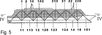
図4〜図7に、(何れも詳細には図示してない)長手隔壁(複数)、横手隔壁(複数)及び中間デッキ(複数)をすべて含む船底部113全体が立体骨組構造1の下弦部11を構成する本発明の船舶としての巡航船の一例を示した。立体骨組構造1の上弦部10は、水平トラスフレーム板状構造102から形成される。腹材(複数)12は、長手方向及び横手方向に形成される複数の直立トラスフレーム板状構造123、124からなるシステムを形成し、該トラスフレーム板状構造を介して、上弦部10及び下弦部11が曲げ−、剪断−及びねじれ抵抗的に互いに結合される。矩形(四角筒状)横断面130により、内装構造2のフレキシビリティは最大限大きくなることが可能となる。巡航船の内装構造2は、居住区(複数)220を有し、その照明面積は、外部船内壁(複数)210に切り込み形成されたアトリウム(複数)221によって拡大される。乾弦の上方の船内壁(複数)210は、完全にガラス嵌装することができるため、船体外板(船内壁)210の大部分は、耐食性材料から構成することができる。
4 to 7, the
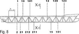
図8〜図10に、二重底111が立体骨組構造体1の下弦部11を構成する本発明の船舶としてのコンテナ船の一例を示した。骨組構造体1は、2つの3ピース支持体(フレーム)により組立てられた筒状横断面132として構築された三角形横断面を有する。上弦部10は、船首から船尾まで延在し連結されて水平ラーメンフレーム板状構造101を形成する3つの弦部材からなり、他方、下弦部11は、二重底111のシェル状ボデーから構成される。立体骨組構造体1の腹材(複数)12は、貨物室(複数)が自由に使えるように配置される。比較的軽量の複数の腹材12によって曲げ−、剪断−及びねじり抵抗的に離隔状態に保持される上弦部10及び下弦部11に力を集中させることにより、比較的薄い板材で、外皮構造体(船内壁)210、内装構造長手壁211及び内装構造横手壁212のような面の割合が大きい(flaechenintensiv)すべての構造グループで使用される鋼を代替することができる。
FIGS. 8 to 10 show an example of a container ship as a ship of the present invention in which the
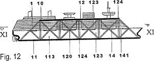
図11〜図13に、円形(ないし丸味をつけた形状)のデッキ構造体(複数)を有する本発明の船舶としての巡航船の一例を示した。2つの直立トラスフレーム板状構造123は、キール線の左右において下弦部11と上弦部10とを結合し、及び居住区220間を連絡するための長手方向中央フロアを形成する。補強中間デッキ14は、水平トラスフレーム板状構造141から形成され、及び長手方向に形成されるトラスフレーム板状構造を安定化する。船底部113の外被構造110全体は、骨組構造体1の下弦部11として役立つ。乾弦の上方に設けられる居住塔は、大幅に(大部分が)ガラスから構成される船内壁210と、迫り出しバルコニーとを有する。
FIGS. 11 to 13 show an example of a cruise ship as a ship of the present invention having a circular (or rounded) deck structure (plural). The two upright truss frame plate-
図14及び図15に、本発明の船舶としての巡航船の一例の中央セグメントを示した。船底部113は、長手方向及び横手方向に形成されるラーメンフレーム板状構造121、122によって上弦部10と結合し、立体骨組構造体1を構成する。上弦部10は、リブプレート(Rippenplatte)103として構成され、他方、下弦部11としては、二重底111の外被110並びに(何れも詳細には図示してない)長手隔壁(複数)、横手隔壁(複数)及び中間デッキ(複数)を含む船底部113全体が使用される。上部のデッキ(複数)202は、何れも、引張部材(複数)201によって、上部リブプレート103に懸設され、他方、下部のデッキ(複数)202は、何れも、内装構造支材(複数)200によって支持される。
14 and 15 show a central segment of an example of a cruise ship as a ship of the present invention. The
図16及び図17に、本発明の船舶としての巡航船の一例の中央セグメントを示した。船底部113は、外部船内壁212の範囲において、腹材(複数)12によって上弦部10と結合する。腹材(複数)12は、鋼製箱形支持体151からなり、引張対角斜材(プレース、複数)150によって長手方向及び横手方向において補強(強化)される。節点結合部120において、引張ワイヤ(Zugzeile)150が、フォーク型ワイヤ係合ヘッド(Gabelseilkoepfen)によって箱形支持体151に結合される。また、サドル状案内部材(Umlenksaettel)を介して1つの区画からその隣の区画へ通してワイヤを案内することも可能である。この場合、螺着された大面積のワイヤ挟掴部材(Seilklemmen)は、(複数の)ディファレンシャルフォース(Differenzkraefte)を受容する。これらワイヤを水圧で加圧することによって、船体構造全体が加圧されるため、箱形支持体151も圧縮応力を受ける。かくして、船体の変形を極く僅かなものに抑制することができる。居住区画(複数)220は、航行方向に対する直交方向に分離されたユニット(複数)にそれぞれ配されるため、すべての空間及びキャビンの照明(採光)を確保することができる。上弦部10は、リブプレート103から構成され、他方、下弦部11は、長手隔壁(複数)、横手隔壁(複数)及び中間デッキ(複数)をすべて包含する船底113全体を含む。上部のデッキ(複数)202は、何れも、引張部材(複数)201によって、上甲板を形成するリブプレート103に懸設され、他方、下層のデッキ(複数)202は、何れも、内装構造支材(複数)200によって、船底部113の二重底111上に支持配設される。
16 and 17 show a central segment of an example of a cruise ship as a ship of the present invention. The
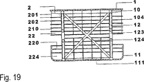
図18及び図19に、本発明の船舶としての巡航船の一例の中央セグメントを示した。船底部113は、船体内部に配設された腹材(複数)12によって上弦部10と結合する。長手方向に実質的に平行に形成される2つのトラスフレーム板状構造123は、船体を長手方向に沿って3つのセグメントに分割する。そのうちの中央のセグメントは、横手方向直立トラスフレーム板状構造122[124]によって一定の間隔を置いて補強される。船底部113によって構成される下弦部11への力の導入及び一貫した(1ピースの)リブプレート103から構成される上弦部10への力の導入は、長手方向及び横手方向に配設されたリブ(複数)を介して行われる。上弦部10も下弦部11も、鋼及びコンクリートからなる複合プレート104、112として構成される。上部部分のデッキ(複数)202は、何れも、引張部材(複数)201によって、上弦部10の複合プレート104に懸設され、他方、下方部分の中間デッキ(複数)202は、何れも、内装構造支材(複数)200を介して、二重底111上に架設される。
18 and 19 show a central segment of an example of a cruise ship as a ship of the present invention. The
図21及び図22に、本発明の船舶としての巡航船の一例の前部セグメントを示した。船底部113は、腹材(複数)12によって上弦部10と結合する。長手方向に形成される直立トラスフレーム板状構造123は、リブプレート103として立体骨組構造体1の上弦部10を構成する上甲板と船底部113を直接的に結合する。水平トラスフレーム板状構造141は、乾弦の高さ位置に補強中間デッキ14を形成する。下弦部11は、(何れも詳細には図示しない)長手隔壁(複数)、横手隔壁(複数)及び中間デッキ(複数)を含む船底部113全体から構成される。乾弦の上方の内装構造2は、(船舶の)全体的な支持機能から実質的に解放されて(免れて)おり、ガラス嵌装された船内壁(複数)210及び7つの居住区デッキ202から構成される。
21 and 22 show a front segment of an example of a cruise ship as a ship of the present invention. The
1 立体骨組構造体
10 上弦部
100 弦部材
101 水平ラーメンフレーム板状構造(liegende Rahmenscheibe)
102 水平トラスフレーム板状構造(liegende Fachwerkscheibe)
103 リブプレート
104 複合プレート
11 下弦部
110 船底部の外被構造
111 二重底
112 複合シェル
113 船底部(キッ水線よりの下部)
12 腹材(Fuellstaebe)
120 節点結合部
121 長手方向直立ラーメンフレーム板状構造
122 横手方向直立ラーメンフレーム板状構造
123 長手方向直立トラスフレーム板状構造
124 横手方向直立トラスフレーム板状構造
13 複弦材横断面
130 矩形(四角筒状)横断面
131 十字状横断面
132 組立てられた筒状横断面
14 補強デッキ
140 水平ラーメンフレーム板状構造
141 水平トラスフレーム板状構造
15 棒状支持部材
150 引張斜材(引張部材)
151 箱形横断面
152 円管状横断面
2 支持機能を有しない内装構造
20 スケルトン構造の内装構造骨格構造
200 内装構造支材
201 内装構造引張部材
202 内装構造デッキ
21 内装構造壁(Ausbauwand)
210 船内壁(Bordwand)
211 内装構造長手壁
212 内装構造横手壁
22 内装構造空間
220 居住区画
221 アトリウム
222 横手方向開口(照明開口)
223 内装構造貨物室
23 走行自在のブリッジ
DESCRIPTION OF
102 Horizontal truss frame structure (liegende Fachwerkscheibe)
103 Rib plate 104
12 Abdomen (Fuellstaebe)
120
151 Box-shaped cross section 152 Circular
210 Inner Wall (Bordwand)
211 Interior structure
223
Claims (30)
前記支持構造は、1つの上弦部(10)、1つの下弦部(11)及び複数の腹材(12)を有する立体骨組構造体(1)を有し、
前記複数の腹材(12)が前記上弦部(10)と前記下弦部(11)とを離隔状態に保持しかつ曲げ−、剪断−及びねじり抵抗的に互いに結合することにより、前記立体骨組構造体(1)が船体の全体的な支持機能を有し、前記内装構造(2)は船体の全体的な支持機能から実質的に解放されて配されること、及び
前記内装構造(2)は、複数の長手壁(211)、複数の横手壁(212)、複数の船内壁(210)及び複数のデッキ(202)を有すること
を特徴とする船舶。 In a ship having a hull structure having at least a support structure, ship bottom portion formed in accordance with the interior structure (2) and hydrodynamic viewpoint (113),
The support structure includes a three-dimensional frame structure (1) having one upper chord part (10), one lower chord part (11), and a plurality of abdomen (12),
The plurality of abdominal materials (12) hold the upper chord part (10) and the lower chord part (11) in a separated state and are coupled to each other in a bending-, shearing-, and torsion-resistant manner, thereby the three-dimensional frame structure has a body (1) the overall support capability of the hull, the interior structure (2) is Rukoto arranged is substantially freed from the overall support function of the hull, and
The interior structure (2) includes a plurality of longitudinal walls (211), a plurality of transverse walls (212), a plurality of ship inner walls (210), and a plurality of decks (202) .
を特徴とする請求項1に記載の船舶。The ship according to claim 1 , comprising a plurality of cargo compartments (223).
を特徴とする請求項1又は2に記載の船舶。The ship according to claim 1 or 2 , wherein the three-dimensional frame structure (1) has a double-string cross section (13).
を特徴とする請求項3に記載の船舶。Ship according to claim 3 , characterized in that the three-dimensional frame structure (1) has a rectangular cross section (130).
を特徴とする請求項3又は4に記載の船舶。The ship according to claim 3 or 4 , wherein the three-dimensional frame structure (1) has a cross-shaped cross section (131).
を特徴とする請求項3〜5の何れか一項に記載の船舶。The ship according to any one of claims 3 to 5 , wherein the three-dimensional frame structure (1) has an assembled cylindrical cross section (132).
を特徴とする請求項1〜6の何れか一項に記載の船舶。The ship according to any one of claims 1 to 6 , wherein the three-dimensional frame structure (1) has at least one reinforcing deck (14).
を特徴とする請求項7に記載の船舶。The ship according to claim 7 , wherein the reinforcing deck (14) has a horizontal frame structure (140).
を特徴とする請求項7又は8に記載の船舶。The ship according to claim 7 or 8 , wherein the reinforcing deck (14) has a horizontal truss frame plate structure (141).
を特徴とする請求項1〜9の何れか一項に記載の船舶。The space frame structure (1) is any of claim 1-9, characterized in (Polygonzugartig) being adapted to hydrodynamic form Nitaishi polygonal arrangement shape (outline) of the vessel bottom portion (113) A ship according to any one of the above.
を特徴とする請求項1〜10の何れか一項に記載の船舶。The upper chord part (10) of the three-dimensional frame structure (1) is a chord member (100), a horizontal frame frame plate structure (101), a horizontal truss frame plate structure (102), a rib plate (103), or steel. and / or vessel according to any one of claim 1 to 10, characterized in that it has a concrete composite plate (104).
を特徴とする請求項1〜11の何れか一項に記載の船舶。The lower chord part of the three-dimensional frame structure (1) includes a shell structure (110) of the ship bottom part, a double bottom (111), a composite shell (112) made of steel and concrete, and / or a plurality of longitudinal partition walls, The ship according to any one of claims 1 to 11 , comprising the entire ship bottom (113) including all of a plurality of transverse bulkheads and a plurality of intermediate decks.
を特徴とする請求項1〜12の何れか一項に記載の船舶。The plurality of abdominal materials (12) are assembled according to the type of the frame frame structure (121) formed in the longitudinal direction and / or the truss frame plate structure (123) formed in the longitudinal direction. The ship according to any one of claims 1 to 12 .
を特徴とする請求項13の船舶。The ship according to claim 13 , wherein the plurality of abdomen (12) directly connects the ship bottom (113) with the upper chord (10) at a keel line.
を特徴とする請求項13又は14に記載の船舶。Wherein the plurality of web members (12), or in the plane of the outer vessel inner wall in the left and right keel line, claim, characterized in said vessel bottom portion (113) to directly coupled to the upper chord section (10) 13 Or the ship of 14 .
を特徴とする請求項1〜15の何れか一項に記載の船舶。The plurality of abdominal members are coupled to the upper chord part (10) and the lower chord part (11) in a pivotable or bending resistance manner via a plurality of node coupling parts (120). The ship according to any one of claims 1 to 15 .
を特徴とする請求項1〜16の何れか一項に記載の船舶。The plurality of bellows (12) comprises a plurality of rod-like support members (15) having a box-shaped cross section (151), a circular profile (Rundhohlprofil) cross section (152) and / or a circular tube cross section (152). The marine vessel according to any one of claims 1 to 16 , characterized by comprising:
を特徴とする請求項17に記載の船舶。18. The ship according to claim 17 , wherein the plurality of rod-shaped support members (15) have an internal transverse bulkhead having an entrance opening (an opening through which an object such as a human or a robot can pass through for maintenance or the like). .
を特徴とする請求項1〜18の何れか一項に記載の船舶。The ship according to any one of claims 1 to 18 , wherein the plurality of abdomen (12) has only a plurality of tension members (150).
を特徴とする請求項1〜19の何れか一項に記載の船舶。The interior structure includes a skeleton-structured secondary support framework (20) having a plurality of interior structure supports (200), a plurality of interior structure tension members (201), and a plurality of interior structure decks (202). The ship according to any one of claims 1 to 19 , wherein
を特徴とする請求項20に記載の船舶。The plurality of interior structure support members (200) are installed on the double bottom (111), and the plurality of interior structure tension members (201) are suspended from the upper chord part (10). The ship according to claim 20 .
を特徴とする請求項1〜21の何れか一項に記載の船舶。The interior structure (2) has a plurality of planar elements that form members of the plurality of outer ship inner walls (210) and / or the plurality of longitudinal walls and transverse walls (211 and 212). The ship according to any one of claims 1 to 21 , characterized in that
を特徴とする請求項1〜22の何れか一項に記載の船舶。A space program for a passenger ship with a longitudinal axis extending in the navigation direction and the interior structure (2) depending on the type of residential space (220), atrium (221), lighting opening (222) and / or similar functional space The ship according to any one of claims 1 to 22 , wherein each element of the spatial program partitions the hull in a direction orthogonal to the longitudinal axis.
を特徴とする請求項1〜23の何れか一項に記載の船舶。The interior structure (2) has a plurality of residence blocks and / or residence buildings that can be illuminated from all directions and have independent internal development systems (Erschliessungssystem) each having a plurality of stairs and / or a plurality of elevators. The ship according to any one of claims 1 to 23 , wherein:
を特徴とする請求項1〜24の何れか一項に記載の船舶。It has a plurality of inner walls (210) which are completely glazed (glass-fitted) and / or separated by a composite panel made of lightweight corrosion-resistant material as an interior structural wall (21) above the freeboard. The ship according to any one of claims 1 to 24 .
を特徴とする請求項1〜25の何れか一項に記載の船舶。A plurality of interior decks (202) having a lightweight steel frame structure with trapezoidal sheet metal tension (Trapezblechschalung) and having a utility space (Installationsraum) between the floor structure and the suspended ceiling The ship according to any one of claims 1 to 25 , characterized by comprising:
を特徴とする請求項1〜26の何れか一項に記載の船舶。A plurality of interior structural walls (211 and 212) having a plurality of lightweight metal stand walls (Metallstaenderwaende) each having an outer plate composed of a plurality of plaster boards (Gipskartonplatten). The ship according to any one of 26 .
を特徴とする請求項1〜27の何れか一項に記載の船舶。A plurality of interior walls (210), a plurality of interior structure longitudinal walls (211) and a plurality of lightweight composite plates (such as laser-welded steel sandwich members) or in particular GFK (glass fiber reinforced plastic) sandwich members The ship according to any one of claims 1 to 27 , further comprising: an interior structure lateral wall (212).
を特徴とする請求項1〜28の何れか一項に記載の船舶。The said ship bottom part (113) has a longitudinal partition and / or a transverse partition which are arranged as a film | membrane which applied the tensile stress to each flame | frame division comprised from these abdominal materials (12). Item 29. The ship according to any one of Items 1 to 28 .
を特徴とする請求項1〜29の何れか一項に記載の船舶。30. The interior structure (2) according to any one of claims 1 to 29 , characterized in that the interior structure (2) has a travelable bridge (23) such as a crane provided in the upper chord material for work in a cargo compartment. The listed ship.
Applications Claiming Priority (3)
| Application Number | Priority Date | Filing Date | Title |
|---|---|---|---|
| DE2001151085 DE10151085C1 (en) | 2001-10-16 | 2001-10-16 | Ship or submarine, for passengers or cargo, has carrier frame with modular skeletal structure providing all support functions for eliminating loading of water-tight outer cladding |
| DE2002139926 DE10239926A1 (en) | 2002-08-30 | 2002-08-30 | Sea-going cruise or container ship has box frame steel hull and steel sandwich superstructure |
| PCT/EP2002/011592 WO2003033338A1 (en) | 2001-10-16 | 2002-10-16 | Ship with composite structure |
Publications (3)
| Publication Number | Publication Date |
|---|---|
| JP2005505473A JP2005505473A (en) | 2005-02-24 |
| JP2005505473A5 JP2005505473A5 (en) | 2006-01-05 |
| JP4369753B2 true JP4369753B2 (en) | 2009-11-25 |
Family
ID=26010391
Family Applications (1)
| Application Number | Title | Priority Date | Filing Date |
|---|---|---|---|
| JP2003536095A Expired - Fee Related JP4369753B2 (en) | 2001-10-16 | 2002-10-16 | Composite structure ship |
Country Status (11)
| Country | Link |
|---|---|
| EP (1) | EP1465802B1 (en) |
| JP (1) | JP4369753B2 (en) |
| KR (1) | KR100959819B1 (en) |
| CN (1) | CN100509544C (en) |
| AT (1) | ATE296748T1 (en) |
| DE (1) | DE50203305D1 (en) |
| DK (1) | DK1465802T3 (en) |
| ES (1) | ES2242894T3 (en) |
| HK (1) | HK1073284A1 (en) |
| PT (1) | PT1465802E (en) |
| WO (1) | WO2003033338A1 (en) |
Families Citing this family (5)
| Publication number | Priority date | Publication date | Assignee | Title |
|---|---|---|---|---|
| CN102745307B (en) * | 2012-06-29 | 2015-02-18 | 深圳市海斯比船艇科技股份有限公司 | Manufacturing method of ship |
| CN107554686A (en) * | 2017-05-04 | 2018-01-09 | 江苏省船舶设计研究所有限公司 | A kind of ship heat insulating and corrosion arbor hull based on nano coating |
| CN110162881B (en) * | 2019-05-22 | 2023-05-16 | 中国船舶工业集团公司第七0八研究所 | Method for determining ultimate bearing capacity of midship structure under bending, shearing and twisting combination |
| CN114919710A (en) * | 2022-06-09 | 2022-08-19 | 中国舰船研究设计中心 | Net frame type box floating raft structure and design method thereof |
| KR102587609B1 (en) | 2022-08-02 | 2023-10-12 | 주식회사 크레파머티리얼즈 | Resist composition for lift-off process |
Family Cites Families (7)
| Publication number | Priority date | Publication date | Assignee | Title |
|---|---|---|---|---|
| DE443599C (en) * | 1925-06-23 | 1927-05-03 | Gustav Wrobbel Dr Ing | Construction system for iron ships with diagonal bracing |
| US4138960A (en) * | 1977-04-22 | 1979-02-13 | Bergstrom Lars R | Sailboat construction |
| ATE103141T1 (en) * | 1989-07-07 | 1994-04-15 | Nestle Sa | PROTEIN HYDROLYSIS. |
| NL1006995C2 (en) * | 1997-04-29 | 1998-11-02 | Schijndel & De Hoog V O F Van | Method of forming a structure and structure thus formed. |
| DE19733851A1 (en) * | 1997-08-01 | 1998-04-02 | Vincent Dipl Ing Boell | Base module for construction of ships' hulls of different length and beam |
| FI974010A0 (en) * | 1997-10-21 | 1997-10-21 | Kuntoutusyhtymae Rehab Group O | Jakt planerad Foer hotellbruk |
| DE29919825U1 (en) * | 1999-11-12 | 2000-01-27 | Lethe Metallbau Gmbh | Component for creating walls, in particular interior walls, and / or ceilings, especially on ships |
-
2002
- 2002-10-16 DE DE50203305T patent/DE50203305D1/en not_active Expired - Lifetime
- 2002-10-16 AT AT02790292T patent/ATE296748T1/en not_active IP Right Cessation
- 2002-10-16 KR KR1020047005662A patent/KR100959819B1/en not_active IP Right Cessation
- 2002-10-16 EP EP02790292A patent/EP1465802B1/en not_active Expired - Lifetime
- 2002-10-16 CN CNB028204778A patent/CN100509544C/en not_active Expired - Fee Related
- 2002-10-16 DK DK02790292T patent/DK1465802T3/en active
- 2002-10-16 JP JP2003536095A patent/JP4369753B2/en not_active Expired - Fee Related
- 2002-10-16 ES ES02790292T patent/ES2242894T3/en not_active Expired - Lifetime
- 2002-10-16 WO PCT/EP2002/011592 patent/WO2003033338A1/en active IP Right Grant
- 2002-10-16 PT PT02790292T patent/PT1465802E/en unknown
-
2005
- 2005-07-12 HK HK05105942.3A patent/HK1073284A1/en not_active IP Right Cessation
Also Published As
| Publication number | Publication date |
|---|---|
| HK1073284A1 (en) | 2005-09-30 |
| EP1465802B1 (en) | 2005-06-01 |
| PT1465802E (en) | 2005-08-31 |
| ATE296748T1 (en) | 2005-06-15 |
| CN1582240A (en) | 2005-02-16 |
| JP2005505473A (en) | 2005-02-24 |
| KR100959819B1 (en) | 2010-05-28 |
| DK1465802T3 (en) | 2005-08-15 |
| WO2003033338A1 (en) | 2003-04-24 |
| DE50203305D1 (en) | 2005-07-07 |
| ES2242894T3 (en) | 2005-11-16 |
| CN100509544C (en) | 2009-07-08 |
| KR20050037414A (en) | 2005-04-21 |
| EP1465802A1 (en) | 2004-10-13 |
Similar Documents
| Publication | Publication Date | Title |
|---|---|---|
| JP2579927B2 (en) | Passenger liner | |
| JPS5878895A (en) | Floor structure of upper loading chamber of aircraft | |
| JP4369753B2 (en) | Composite structure ship | |
| JP2005505473A5 (en) | ||
| CN111661263B (en) | Carry on floating platform of container functional unit fast | |
| US4714041A (en) | Structure of surface effect ship with side walls | |
| US8939101B2 (en) | Passenger ship of which the superstructure is equipped with at least one arch | |
| US4638754A (en) | Vessel hull and bulkheads construction employing curved plating | |
| JP3295427B2 (en) | Superstructure of a double-hulled ship | |
| PL179352B1 (en) | Structural component for building structures | |
| CN113602412A (en) | Titanium alloy-based shipboard ballast water tank and diving system | |
| CN104494778B (en) | Glass fiber hull and ferry glass reinforced plastic boat | |
| WO2016147103A2 (en) | Modular floating platform | |
| DE10151085C1 (en) | Ship or submarine, for passengers or cargo, has carrier frame with modular skeletal structure providing all support functions for eliminating loading of water-tight outer cladding | |
| RU2507103C1 (en) | Side bulkhead | |
| CN218617057U (en) | Bulk cargo ship bottom stool structure and ship | |
| CN219948483U (en) | Transverse bulkhead structure of container ship with lightweight platform | |
| US4138960A (en) | Sailboat construction | |
| EP0536130B1 (en) | Vessel hull | |
| Bogdaniuk et al. | Concept of barge hull structure made of extruded aluminium panels | |
| CN114919690A (en) | Roll-on/roll-off ship superstructure arrangement structure and damping structure | |
| DE10239926A1 (en) | Sea-going cruise or container ship has box frame steel hull and steel sandwich superstructure | |
| Klee et al. | Deformations of a Large Hall: Structural Design and Analysis | |
| JPH11124084A (en) | Pontoon-type floating structure | |
| JPS59213586A (en) | Hull structure |
Legal Events
| Date | Code | Title | Description |
|---|---|---|---|
| A529 | Written submission of copy of amendment under article 34 pct |
Free format text: JAPANESE INTERMEDIATE CODE: A529 Effective date: 20040616 |
|
| RD02 | Notification of acceptance of power of attorney |
Free format text: JAPANESE INTERMEDIATE CODE: A7422 Effective date: 20040622 |
|
| A521 | Request for written amendment filed |
Free format text: JAPANESE INTERMEDIATE CODE: A523 Effective date: 20040622 |
|
| A521 | Request for written amendment filed |
Free format text: JAPANESE INTERMEDIATE CODE: A523 Effective date: 20050926 |
|
| A621 | Written request for application examination |
Free format text: JAPANESE INTERMEDIATE CODE: A621 Effective date: 20050926 |
|
| A711 | Notification of change in applicant |
Free format text: JAPANESE INTERMEDIATE CODE: A711 Effective date: 20051228 |
|
| A521 | Request for written amendment filed |
Free format text: JAPANESE INTERMEDIATE CODE: A821 Effective date: 20051228 |
|
| A131 | Notification of reasons for refusal |
Free format text: JAPANESE INTERMEDIATE CODE: A131 Effective date: 20071127 |
|
| A601 | Written request for extension of time |
Free format text: JAPANESE INTERMEDIATE CODE: A601 Effective date: 20080227 |
|
| A602 | Written permission of extension of time |
Free format text: JAPANESE INTERMEDIATE CODE: A602 Effective date: 20080305 |
|
| A601 | Written request for extension of time |
Free format text: JAPANESE INTERMEDIATE CODE: A601 Effective date: 20080327 |
|
| A602 | Written permission of extension of time |
Free format text: JAPANESE INTERMEDIATE CODE: A602 Effective date: 20080403 |
|
| A601 | Written request for extension of time |
Free format text: JAPANESE INTERMEDIATE CODE: A601 Effective date: 20080428 |
|
| A602 | Written permission of extension of time |
Free format text: JAPANESE INTERMEDIATE CODE: A602 Effective date: 20080508 |
|
| A521 | Request for written amendment filed |
Free format text: JAPANESE INTERMEDIATE CODE: A523 Effective date: 20080527 |
|
| A02 | Decision of refusal |
Free format text: JAPANESE INTERMEDIATE CODE: A02 Effective date: 20080826 |
|
| A521 | Request for written amendment filed |
Free format text: JAPANESE INTERMEDIATE CODE: A523 Effective date: 20090219 |
|
| A01 | Written decision to grant a patent or to grant a registration (utility model) |
Free format text: JAPANESE INTERMEDIATE CODE: A01 |
|
| A61 | First payment of annual fees (during grant procedure) |
Free format text: JAPANESE INTERMEDIATE CODE: A61 Effective date: 20090828 |
|
| R150 | Certificate of patent or registration of utility model |
Free format text: JAPANESE INTERMEDIATE CODE: R150 |
|
| FPAY | Renewal fee payment (event date is renewal date of database) |
Free format text: PAYMENT UNTIL: 20120904 Year of fee payment: 3 |
|
| FPAY | Renewal fee payment (event date is renewal date of database) |
Free format text: PAYMENT UNTIL: 20130904 Year of fee payment: 4 |
|
| R250 | Receipt of annual fees |
Free format text: JAPANESE INTERMEDIATE CODE: R250 |
|
| R250 | Receipt of annual fees |
Free format text: JAPANESE INTERMEDIATE CODE: R250 |
|
| R250 | Receipt of annual fees |
Free format text: JAPANESE INTERMEDIATE CODE: R250 |
|
| LAPS | Cancellation because of no payment of annual fees |