US4714041A - Structure of surface effect ship with side walls - Google Patents
Structure of surface effect ship with side walls Download PDFInfo
- Publication number
- US4714041A US4714041A US06/849,274 US84927486A US4714041A US 4714041 A US4714041 A US 4714041A US 84927486 A US84927486 A US 84927486A US 4714041 A US4714041 A US 4714041A
- Authority
- US
- United States
- Prior art keywords
- ship
- transverse
- hulls
- surface effect
- central box
- Prior art date
- Legal status (The legal status is an assumption and is not a legal conclusion. Google has not performed a legal analysis and makes no representation as to the accuracy of the status listed.)
- Expired - Fee Related
Links
Images


Classifications
-
- B—PERFORMING OPERATIONS; TRANSPORTING
- B63—SHIPS OR OTHER WATERBORNE VESSELS; RELATED EQUIPMENT
- B63B—SHIPS OR OTHER WATERBORNE VESSELS; EQUIPMENT FOR SHIPPING
- B63B3/00—Hulls characterised by their structure or component parts
- B63B3/14—Hull parts
- B63B3/26—Frames
- B63B3/28—Frames of transverse type; Stringers
-
- B—PERFORMING OPERATIONS; TRANSPORTING
- B63—SHIPS OR OTHER WATERBORNE VESSELS; RELATED EQUIPMENT
- B63B—SHIPS OR OTHER WATERBORNE VESSELS; EQUIPMENT FOR SHIPPING
- B63B1/00—Hydrodynamic or hydrostatic features of hulls or of hydrofoils
- B63B1/02—Hydrodynamic or hydrostatic features of hulls or of hydrofoils deriving lift mainly from water displacement
- B63B1/10—Hydrodynamic or hydrostatic features of hulls or of hydrofoils deriving lift mainly from water displacement with multiple hulls
- B63B1/12—Hydrodynamic or hydrostatic features of hulls or of hydrofoils deriving lift mainly from water displacement with multiple hulls the hulls being interconnected rigidly
Definitions
- the present inention relates to surface effect ships.
- the present invention relates more specifically to a surface effect ship including a catamaran type supported structure with two side hulls connected by a central box structure able to operate either as a displacement vehicle or as an air cushion lifted vehicle.
- these catamaran type surface effect ships include a lifted structure with a central box structure connecting two side hulls which provide the side confinement of the lifting air cushion; on the other hand, this structure is equipped with stern and bow seals able to assist the side hulls for delimiting the lifting air cushion supplied by the pressure air generator.
- the suggested catamaran ship structure designs allowing a large tonnage ship to bear correctly the longitudinal bending stresses, the transverse bending stresses, and the diagonal twist stresses, have a very large weight inconsistent with a surface effect ship operation.
- the present invention improves upon prior designs by suggesting a surface effect ship including a catamaran type supported structure with two side hulls connected by a central box structure, able to operate either as a displacement vehicle or as an air cushion lifted vehicle; this structure is equipped with longitudinal and cross bulkheads providing the subdivision and the integrity of the ship; this structure includes:
- each bulkhead comprising a transverse beam within the box structure with a vertical web extending down within the hulls and strengthened within the box structure by two horizontal flanges, upper and lower respectively.
- the ship structure corresponding to this invention is very light, allowing large tonnage ships equipped with limited power systems to be built.
- the web frame of the transverse beam is stiffened horizontally.
- stiffened transverse bulkheads are located by pair in the bow and the stern of the ship respectively.
- the area where the stiffened bulkheads transverse beam is built-in within the hulls is itself strengthened. More specifically this built-in area is bordered by two main vertical stanchions; a stringer including a main horizontal stiffener and a main vertical stanchion is located near the stringer plate; this one provides an extra thickness, and the strengthened bulkhead within the corner area also provides an extra thickness.
- FIG. 1 shows a schematic perspective view of a surface effect ship according to the present invention.
- FIG. 2 shows a cross-section of this ship, at the midship frame, and shows particularly a right half view of the bulkhead and a left half view of the ship structure.
- FIG. 3 shows a left half view of a reinforced transverse bulkhead in the stern part of the ship.
- FIG. 4 shows another half side view of a second transverse bulkhead located in the stern part of the ship.
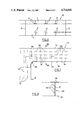
- FIG. 5 shows another cross sectional view of the ship; the left half and right half views of this figure show in more detail first and second reinforced transverse bulkheads respectively located at the bow of the ship.
- FIG. 6 shows a longitudinal cross section of the box.
- FIG. 7 shows a schematic view of the area where the box is built-in within a side hull.
- FIG. 8 shows a cross section of the transverse beam of the reinforced transverse bulkheads, taken along section VIII--VIII in FIG. 7.
- the surface effect ship corresponding to the present invention includes a catamaran type supported structure with two side hulls (10) connected by a central box structure.
- FIG. 1 shows the stern seal means (90) built from several superposed enclosures extending horizontally (91, 92, 93).
- the bow and stern seal means are associated with raising systems (e.g. hoist and cables) allowing the ship to operate as a displacement vehicle.
- raising systems e.g. hoist and cables
- Each hull structure (10) is engineered to bear longitudinal bending moments resulting from the swell.
- the side hulls are equipped with continuous longitudinal stiffeners mainly to bear the longitudinal bending stresses.
- the shell plating and the deck plating include longitudinally arranged plates (11, 12).
- the primary hull stiffeners are continuous and include longitudinal stiffeners (13) and deck stringers (14) to bear the longitudinal bending stresses.
- the secondary hull stiffeners are continuous and include secondary longitudinal hull stiffeners (15) and secondary longitudinal stiffeners (16) to bear longitudinal bending stresses.
- the hulls (10) include bottom frames, side frames, and deck beams 17a.
- the primary and secondary frame spacing (plating and stiffeners) is designed to bear also the local stresses from the hydrostatic pressures due to the impact of the waves and from the air cushion pressure.
- the central box structure (60) connects the two side hulls (10) and acts as a connecting platform between the hulls.
- the central box structure (60) is imbricated within the side walls (10) to insure their connection and to bear the transverse bending stresses due to the swell.
- the central structure includes continuous transverse frames.
- the frames comprise continuous bottom transverse frame 17a and deck beams comprising if necessary, continuous vertical transverse cut-away plates 61.
- the central box structure (60) includes also main longitudinal stiffeners 13 and deck stringers 14 and, if necessary, continuous longitudinal cut-away plates (not shown).
- This central box structure resists the side thrust effects of the air cushion on the internal hulls faces (10) when operating as an air cushion lifted vehicle.
- the central box structure (60) provides a built-in structure for connecting the side hulls (10) thereto in an integral fashion. This built-in structure will be described in detail later. Now it should be noted that this built-in structure includes extra thickness portions and rounded corners in order to offset the pernicious effects of structure discontinuity.
- the thickness of the lower wall (65) of the central box structure (60) is engineered to bear the pressure due to the impact of waves when in the cushioning mode and also the pressure resulting from a sudden loss of lift.
- the transverse watertight bulkheads provided within the side hulls (10) extend into the central box structure (60) as illustrated at (73) in the FIGS. 2 and 6.
- the stiffeners 17b and 18 of the bulkheads (73) within the central box structure (60) are preferably arranged horizontally to optimize the transfer of the transverse stress flow.
- the present invention suggests to resist the diagonal twist stresses, not with a complex and heavy structure including for instance crossed beams, but with transverse strengthened bulkheads (100, 200, 300, 400) that bear the simple transverse bending stresses applied on the stern and the bow of the ship and resulting from twist moments imparted to the hulls especially in the case of diagonal swell.
- the stiffened transverse bulkheads (100, 200, 300, 400) are located as far as possible respectively at the fore part and at the after part within the central box structure (60) and extended into the side hulls (10) as schematically illustrated in FIG. 1.
- these transverse bulkheads are formed by an I-shaped beam with a vertical web frame (101, 201, 301, 401) associated with two transverse plating strips, on the one hand 102, 202, 302, 402) and on the other hand 103, 203, 303, 403) constituting the upper and lower beam flanges respectively.
- the vertical web frame (101, 201, 301, 401) of the beams is stiffened horizontally as schematically illustrated in the figures (104, 204, 304, 404).
- the previously mentioned transverse beams, strengthened to bear the shearing stresses flow are extended by also stiffened bulkheads (113, 213, 313, 413) within the side hulls (10) to transfer the transverse bending and twist stress flow resulting from the twisting effect.
- the lower flange (103, 203, 303, 403) is stiffened by an extra thickness at the stringer plate level (105, 205, 305, 405) and moreover is rounded at the level of maximum stress concentration.
- the web frame of the bulkhead transverse beams (100, 200, 300, 400) is provided with an extra thickness over a whole built-in area.
- this area is bounded by two main stanchions (108, 109; 208, 209; 308, 309; 408, 409) and by an orlop deck (110, 210, 310, 410).
- This framing includes on the one hand a main horizontal stiffener (111, 211, 311, 411) and on the other hand a main vertical stanchion (112, 212, 312, 412).
- the main horizontal stiffener (111-411) is located above the lower level of the central box stiffener within the side hulls (10), and it extends into the central structure box (60).
- the main vertical stanchions (112-412) are located in the upper part of the side hulls (10).
- the figures also show longitudinal fittings (80) provided within the structure and used for instance as air pipes for supplying the supporting air cushion, or as passageways.
- the structure can be built with metal materials, including aluminum alloys, weldable, efficient and resistant to the marine corrosion, or with composite materials, monolithic or sandwich, very efficient, as glass fiber reinforced plastics or kevlar carbone or bore fiber reinforced plastics.
- the longitudinal stiffeners provided within the side hulls to bear the longitudinal bending stresses and the transverse beams within the central box structure to bear the stresses transverse can consist of reinforcing fibers integrated within the composite material.
- the stiffeners should be located longitudinally within the hull to bear the longitudinal bending stresses and to provide stiffness to the whole structure, whilst they should be preferably oriented transversally within the central box structure; however these stiffeners may be locally oriented in a different way to optimize the stress flow transfer resulting from the bending and twist stresses created by the hulls.
Abstract
Description
Claims (10)
Applications Claiming Priority (2)
| Application Number | Priority Date | Filing Date | Title |
|---|---|---|---|
| FR8505311 | 1985-04-09 | ||
| FR8505311A FR2579952A1 (en) | 1985-04-09 | 1985-04-09 | Surface-effect ship structure with lateral keels |
Publications (1)
| Publication Number | Publication Date |
|---|---|
| US4714041A true US4714041A (en) | 1987-12-22 |
Family
ID=9318055
Family Applications (1)
| Application Number | Title | Priority Date | Filing Date |
|---|---|---|---|
| US06/849,274 Expired - Fee Related US4714041A (en) | 1985-04-09 | 1986-04-08 | Structure of surface effect ship with side walls |
Country Status (4)
| Country | Link |
|---|---|
| US (1) | US4714041A (en) |
| CA (1) | CA1265174A (en) |
| ES (1) | ES296995Y (en) |
| NO (1) | NO169162C (en) |
Cited By (10)
| Publication number | Priority date | Publication date | Assignee | Title |
|---|---|---|---|---|
| US4811676A (en) * | 1987-03-27 | 1989-03-14 | Peter Franke | Asymmetric minimum resistance hull |
| WO1992019490A1 (en) * | 1991-05-03 | 1992-11-12 | Kvaerner Mandal A.S | Method for ferry transport of vehicles and a ferry system for transport of vehicles |
| US6293216B1 (en) | 1999-11-16 | 2001-09-25 | Bruce R. Barsumian | Surface effect ship (SES) hull configuration having improved high speed performance and handling characteristics |
| US6604478B2 (en) | 1999-11-16 | 2003-08-12 | Bruce R. Barsumian | Hull configuration utilizing multiple effects for enhanced speed, range and efficiency |
| WO2004024552A2 (en) * | 2002-09-12 | 2004-03-25 | Textron Inc.(A Delaware, Us Corporation) | Hybrid catamaran air cushion ship |
| US20060243182A1 (en) * | 2004-09-15 | 2006-11-02 | Armstrong Neville A | Construction of amahs |
| AU2003274978B2 (en) * | 2002-09-12 | 2010-12-16 | Textron Innovations Inc. | Hybrid catamaran air cushion ship |
| WO2014174311A1 (en) * | 2013-04-26 | 2014-10-30 | Northern Sound Limited | A method of manufacturing a structure |
| USD804990S1 (en) | 2012-10-13 | 2017-12-12 | Gibbs Technologies Limited | Amphibious vehicle |
| KR20180132849A (en) * | 2016-04-11 | 2018-12-12 | 케이플로 디벨롭먼트 | A catamaran hull with a hybrid structure and a ship using the hull |
Citations (7)
| Publication number | Priority date | Publication date | Assignee | Title |
|---|---|---|---|---|
| US2405115A (en) * | 1942-09-25 | 1946-08-06 | Floating Stations Ltd | Floating structure |
| US2464957A (en) * | 1945-02-27 | 1949-03-22 | Garfield A Wood | Boat |
| GB1210973A (en) * | 1968-03-05 | 1970-11-04 | Hovermarine Ltd | Improvements in or relating to marine craft |
| GB1242131A (en) * | 1968-02-24 | 1971-08-11 | Hovermarine Ltd | Flexible walls for containing fluid |
| GB1475084A (en) * | 1973-07-24 | 1977-06-01 | Murthy T | Semi-submerged air cushion vehicle |
| FR2422535A1 (en) * | 1978-04-10 | 1979-11-09 | Guienne Paul | Folding skirt enclosure for air cushion vehicle keel - has sections closed by winch or jack and made airtight when extended by twin flexible horn sections |
| US4548154A (en) * | 1983-07-11 | 1985-10-22 | Hitachi Zosen Corporation | Double hulled ship with longitudinal reinforcements |
-
1986
- 1986-04-08 CA CA000506056A patent/CA1265174A/en not_active Expired - Lifetime
- 1986-04-08 US US06/849,274 patent/US4714041A/en not_active Expired - Fee Related
- 1986-04-08 NO NO861356A patent/NO169162C/en unknown
- 1986-04-08 ES ES1986296995U patent/ES296995Y/en not_active Expired
Patent Citations (7)
| Publication number | Priority date | Publication date | Assignee | Title |
|---|---|---|---|---|
| US2405115A (en) * | 1942-09-25 | 1946-08-06 | Floating Stations Ltd | Floating structure |
| US2464957A (en) * | 1945-02-27 | 1949-03-22 | Garfield A Wood | Boat |
| GB1242131A (en) * | 1968-02-24 | 1971-08-11 | Hovermarine Ltd | Flexible walls for containing fluid |
| GB1210973A (en) * | 1968-03-05 | 1970-11-04 | Hovermarine Ltd | Improvements in or relating to marine craft |
| GB1475084A (en) * | 1973-07-24 | 1977-06-01 | Murthy T | Semi-submerged air cushion vehicle |
| FR2422535A1 (en) * | 1978-04-10 | 1979-11-09 | Guienne Paul | Folding skirt enclosure for air cushion vehicle keel - has sections closed by winch or jack and made airtight when extended by twin flexible horn sections |
| US4548154A (en) * | 1983-07-11 | 1985-10-22 | Hitachi Zosen Corporation | Double hulled ship with longitudinal reinforcements |
Cited By (14)
| Publication number | Priority date | Publication date | Assignee | Title |
|---|---|---|---|---|
| US4811676A (en) * | 1987-03-27 | 1989-03-14 | Peter Franke | Asymmetric minimum resistance hull |
| WO1992019490A1 (en) * | 1991-05-03 | 1992-11-12 | Kvaerner Mandal A.S | Method for ferry transport of vehicles and a ferry system for transport of vehicles |
| US6293216B1 (en) | 1999-11-16 | 2001-09-25 | Bruce R. Barsumian | Surface effect ship (SES) hull configuration having improved high speed performance and handling characteristics |
| US6604478B2 (en) | 1999-11-16 | 2003-08-12 | Bruce R. Barsumian | Hull configuration utilizing multiple effects for enhanced speed, range and efficiency |
| WO2004024552A3 (en) * | 2002-09-12 | 2004-07-01 | Textron Inc A Delaware Us Corp | Hybrid catamaran air cushion ship |
| US20040112268A1 (en) * | 2002-09-12 | 2004-06-17 | Textron Inc. (a Delaware, US corporation) | Hybrid catamaran air cushion ship |
| WO2004024552A2 (en) * | 2002-09-12 | 2004-03-25 | Textron Inc.(A Delaware, Us Corporation) | Hybrid catamaran air cushion ship |
| US7013826B2 (en) | 2002-09-12 | 2006-03-21 | Textron Innovations Inc. | Hybrid catamaran air cushion ship |
| AU2003274978B2 (en) * | 2002-09-12 | 2010-12-16 | Textron Innovations Inc. | Hybrid catamaran air cushion ship |
| US20060243182A1 (en) * | 2004-09-15 | 2006-11-02 | Armstrong Neville A | Construction of amahs |
| US7237500B2 (en) * | 2004-09-15 | 2007-07-03 | Austal Ships Pty Ltd | Hull construction for side hulls of trimaran and the like |
| USD804990S1 (en) | 2012-10-13 | 2017-12-12 | Gibbs Technologies Limited | Amphibious vehicle |
| WO2014174311A1 (en) * | 2013-04-26 | 2014-10-30 | Northern Sound Limited | A method of manufacturing a structure |
| KR20180132849A (en) * | 2016-04-11 | 2018-12-12 | 케이플로 디벨롭먼트 | A catamaran hull with a hybrid structure and a ship using the hull |
Also Published As
| Publication number | Publication date |
|---|---|
| CA1265174A (en) | 1990-01-30 |
| ES296995Y (en) | 1989-03-16 |
| NO169162B (en) | 1992-02-10 |
| NO169162C (en) | 1992-05-20 |
| NO861356L (en) | 1986-10-10 |
| ES296995U (en) | 1988-08-16 |
Similar Documents
| Publication | Publication Date | Title |
|---|---|---|
| US4714041A (en) | Structure of surface effect ship with side walls | |
| AU2004318006B2 (en) | Double-hull vessel converted from a single-hull vessel and method of performing the same | |
| CN111661235A (en) | Semi-submersible type multifunctional transport dismounting ship | |
| CN212921866U (en) | Semi-submersible type multifunctional transport dismounting ship | |
| US4304190A (en) | Ferry boat | |
| CN113928482A (en) | Thin film type LNG ship cargo hold structure applied to inland river | |
| EP1470039B1 (en) | Hull assembly for an aquatic vessel and high speed catamaran vessel | |
| US20080196648A1 (en) | Mechanism for collapsible catamaran | |
| US4936237A (en) | Dual boat hull | |
| US2412578A (en) | Dry dock pontoon construction | |
| US3295152A (en) | Sailboat | |
| EP0242485B1 (en) | Structure of a surface-effect ship with side keels | |
| CN212386643U (en) | Hull broadside structure of semi-submersible multifunctional transport assembly and disassembly ship | |
| GB2163393A (en) | A semi-submersible vessel | |
| CN213535004U (en) | Non-continuous type upper-building transition node structure of ro-ro passenger ship | |
| VESSELS | 2019 | |
| EP0536130B1 (en) | Vessel hull | |
| CN217022797U (en) | Cast steel and steel plate mixed high-strength stem structure of container ship | |
| WO2008153413A1 (en) | Deck structural system for a multihull vessel | |
| JPS6324080Y2 (en) | ||
| SU846373A1 (en) | Ship hull | |
| JPH0433192Y2 (en) | ||
| JPH02262489A (en) | Body of container ship | |
| Maxwell | Design of a Trailer Capable, Open Ocean Sailing Yacht | |
| CN117401102A (en) | Watertight transverse bulkhead structure of container ship and container ship comprising same |
Legal Events
| Date | Code | Title | Description |
|---|---|---|---|
| AS | Assignment |
Owner name: ETAT FRANCAIS REPRESENTE PAR LE DELEGUE GENERAL PO Free format text: ASSIGNMENT OF ASSIGNORS INTEREST.;ASSIGNORS:JAFFRE, ROBERT;ROPARS, YVON;REEL/FRAME:004546/0489 Effective date: 19860320 Owner name: ETAT FRANCAIS REPRESENTE PAR LE DELEGUE GENERAL PO Free format text: ASSIGNMENT OF ASSIGNORS INTEREST;ASSIGNORS:JAFFRE, ROBERT;ROPARS, YVON;REEL/FRAME:004546/0489 Effective date: 19860320 |
|
| FEPP | Fee payment procedure |
Free format text: PAYOR NUMBER ASSIGNED (ORIGINAL EVENT CODE: ASPN); ENTITY STATUS OF PATENT OWNER: LARGE ENTITY |
|
| FPAY | Fee payment |
Year of fee payment: 4 |
|
| FPAY | Fee payment |
Year of fee payment: 8 |
|
| REMI | Maintenance fee reminder mailed | ||
| LAPS | Lapse for failure to pay maintenance fees | ||
| FP | Lapsed due to failure to pay maintenance fee |
Effective date: 19991222 |
|
| STCH | Information on status: patent discontinuation |
Free format text: PATENT EXPIRED DUE TO NONPAYMENT OF MAINTENANCE FEES UNDER 37 CFR 1.362 |