JP4365984B2 - Manufacturing method of recycled plastic material - Google Patents
Manufacturing method of recycled plastic material Download PDFInfo
- Publication number
- JP4365984B2 JP4365984B2 JP2000116965A JP2000116965A JP4365984B2 JP 4365984 B2 JP4365984 B2 JP 4365984B2 JP 2000116965 A JP2000116965 A JP 2000116965A JP 2000116965 A JP2000116965 A JP 2000116965A JP 4365984 B2 JP4365984 B2 JP 4365984B2
- Authority
- JP
- Japan
- Prior art keywords
- plastic material
- recycled plastic
- cleaning liquid
- thermoplastic
- producing
- Prior art date
- Legal status (The legal status is an assumption and is not a legal conclusion. Google has not performed a legal analysis and makes no representation as to the accuracy of the status listed.)
- Expired - Fee Related
Links
Images


Classifications
-
- B—PERFORMING OPERATIONS; TRANSPORTING
- B29—WORKING OF PLASTICS; WORKING OF SUBSTANCES IN A PLASTIC STATE IN GENERAL
- B29B—PREPARATION OR PRETREATMENT OF THE MATERIAL TO BE SHAPED; MAKING GRANULES OR PREFORMS; RECOVERY OF PLASTICS OR OTHER CONSTITUENTS OF WASTE MATERIAL CONTAINING PLASTICS
- B29B17/00—Recovery of plastics or other constituents of waste material containing plastics
- B29B17/02—Separating plastics from other materials
-
- B—PERFORMING OPERATIONS; TRANSPORTING
- B41—PRINTING; LINING MACHINES; TYPEWRITERS; STAMPS
- B41J—TYPEWRITERS; SELECTIVE PRINTING MECHANISMS, i.e. MECHANISMS PRINTING OTHERWISE THAN FROM A FORME; CORRECTION OF TYPOGRAPHICAL ERRORS
- B41J2/00—Typewriters or selective printing mechanisms characterised by the printing or marking process for which they are designed
- B41J2/005—Typewriters or selective printing mechanisms characterised by the printing or marking process for which they are designed characterised by bringing liquid or particles selectively into contact with a printing material
- B41J2/01—Ink jet
- B41J2/17—Ink jet characterised by ink handling
- B41J2/175—Ink supply systems ; Circuit parts therefor
- B41J2/17503—Ink cartridges
- B41J2/17559—Cartridge manufacturing
-
- B—PERFORMING OPERATIONS; TRANSPORTING
- B41—PRINTING; LINING MACHINES; TYPEWRITERS; STAMPS
- B41J—TYPEWRITERS; SELECTIVE PRINTING MECHANISMS, i.e. MECHANISMS PRINTING OTHERWISE THAN FROM A FORME; CORRECTION OF TYPOGRAPHICAL ERRORS
- B41J29/00—Details of, or accessories for, typewriters or selective printing mechanisms not otherwise provided for
- B41J29/02—Framework
-
- B—PERFORMING OPERATIONS; TRANSPORTING
- B41—PRINTING; LINING MACHINES; TYPEWRITERS; STAMPS
- B41M—PRINTING, DUPLICATING, MARKING, OR COPYING PROCESSES; COLOUR PRINTING
- B41M5/00—Duplicating or marking methods; Sheet materials for use therein
- B41M5/24—Ablative recording, e.g. by burning marks; Spark recording
-
- B—PERFORMING OPERATIONS; TRANSPORTING
- B29—WORKING OF PLASTICS; WORKING OF SUBSTANCES IN A PLASTIC STATE IN GENERAL
- B29B—PREPARATION OR PRETREATMENT OF THE MATERIAL TO BE SHAPED; MAKING GRANULES OR PREFORMS; RECOVERY OF PLASTICS OR OTHER CONSTITUENTS OF WASTE MATERIAL CONTAINING PLASTICS
- B29B17/00—Recovery of plastics or other constituents of waste material containing plastics
- B29B17/04—Disintegrating plastics, e.g. by milling
- B29B17/0404—Disintegrating plastics, e.g. by milling to powder
-
- B—PERFORMING OPERATIONS; TRANSPORTING
- B29—WORKING OF PLASTICS; WORKING OF SUBSTANCES IN A PLASTIC STATE IN GENERAL
- B29B—PREPARATION OR PRETREATMENT OF THE MATERIAL TO BE SHAPED; MAKING GRANULES OR PREFORMS; RECOVERY OF PLASTICS OR OTHER CONSTITUENTS OF WASTE MATERIAL CONTAINING PLASTICS
- B29B17/00—Recovery of plastics or other constituents of waste material containing plastics
- B29B17/02—Separating plastics from other materials
- B29B2017/0203—Separating plastics from plastics
-
- B—PERFORMING OPERATIONS; TRANSPORTING
- B29—WORKING OF PLASTICS; WORKING OF SUBSTANCES IN A PLASTIC STATE IN GENERAL
- B29B—PREPARATION OR PRETREATMENT OF THE MATERIAL TO BE SHAPED; MAKING GRANULES OR PREFORMS; RECOVERY OF PLASTICS OR OTHER CONSTITUENTS OF WASTE MATERIAL CONTAINING PLASTICS
- B29B17/00—Recovery of plastics or other constituents of waste material containing plastics
- B29B17/02—Separating plastics from other materials
- B29B2017/0213—Specific separating techniques
- B29B2017/0217—Mechanical separating techniques; devices therefor
- B29B2017/0224—Screens, sieves
-
- B—PERFORMING OPERATIONS; TRANSPORTING
- B29—WORKING OF PLASTICS; WORKING OF SUBSTANCES IN A PLASTIC STATE IN GENERAL
- B29B—PREPARATION OR PRETREATMENT OF THE MATERIAL TO BE SHAPED; MAKING GRANULES OR PREFORMS; RECOVERY OF PLASTICS OR OTHER CONSTITUENTS OF WASTE MATERIAL CONTAINING PLASTICS
- B29B17/00—Recovery of plastics or other constituents of waste material containing plastics
- B29B17/02—Separating plastics from other materials
- B29B2017/0213—Specific separating techniques
- B29B2017/0217—Mechanical separating techniques; devices therefor
- B29B2017/0237—Mechanical separating techniques; devices therefor using density difference
- B29B2017/0241—Mechanical separating techniques; devices therefor using density difference in gas, e.g. air flow
-
- B—PERFORMING OPERATIONS; TRANSPORTING
- B29—WORKING OF PLASTICS; WORKING OF SUBSTANCES IN A PLASTIC STATE IN GENERAL
- B29B—PREPARATION OR PRETREATMENT OF THE MATERIAL TO BE SHAPED; MAKING GRANULES OR PREFORMS; RECOVERY OF PLASTICS OR OTHER CONSTITUENTS OF WASTE MATERIAL CONTAINING PLASTICS
- B29B17/00—Recovery of plastics or other constituents of waste material containing plastics
- B29B17/02—Separating plastics from other materials
- B29B2017/0213—Specific separating techniques
- B29B2017/0217—Mechanical separating techniques; devices therefor
- B29B2017/0237—Mechanical separating techniques; devices therefor using density difference
- B29B2017/0244—Mechanical separating techniques; devices therefor using density difference in liquids
-
- B—PERFORMING OPERATIONS; TRANSPORTING
- B29—WORKING OF PLASTICS; WORKING OF SUBSTANCES IN A PLASTIC STATE IN GENERAL
- B29B—PREPARATION OR PRETREATMENT OF THE MATERIAL TO BE SHAPED; MAKING GRANULES OR PREFORMS; RECOVERY OF PLASTICS OR OTHER CONSTITUENTS OF WASTE MATERIAL CONTAINING PLASTICS
- B29B17/00—Recovery of plastics or other constituents of waste material containing plastics
- B29B17/02—Separating plastics from other materials
- B29B2017/0213—Specific separating techniques
- B29B2017/0268—Separation of metals
- B29B2017/0272—Magnetic separation
-
- B—PERFORMING OPERATIONS; TRANSPORTING
- B29—WORKING OF PLASTICS; WORKING OF SUBSTANCES IN A PLASTIC STATE IN GENERAL
- B29B—PREPARATION OR PRETREATMENT OF THE MATERIAL TO BE SHAPED; MAKING GRANULES OR PREFORMS; RECOVERY OF PLASTICS OR OTHER CONSTITUENTS OF WASTE MATERIAL CONTAINING PLASTICS
- B29B17/00—Recovery of plastics or other constituents of waste material containing plastics
- B29B17/02—Separating plastics from other materials
- B29B2017/0213—Specific separating techniques
- B29B2017/0286—Cleaning means used for separation
- B29B2017/0289—Washing the materials in liquids
-
- B—PERFORMING OPERATIONS; TRANSPORTING
- B29—WORKING OF PLASTICS; WORKING OF SUBSTANCES IN A PLASTIC STATE IN GENERAL
- B29K—INDEXING SCHEME ASSOCIATED WITH SUBCLASSES B29B, B29C OR B29D, RELATING TO MOULDING MATERIALS OR TO MATERIALS FOR MOULDS, REINFORCEMENTS, FILLERS OR PREFORMED PARTS, e.g. INSERTS
- B29K2023/00—Use of polyalkenes or derivatives thereof as moulding material
- B29K2023/10—Polymers of propylene
- B29K2023/12—PP, i.e. polypropylene
-
- B—PERFORMING OPERATIONS; TRANSPORTING
- B29—WORKING OF PLASTICS; WORKING OF SUBSTANCES IN A PLASTIC STATE IN GENERAL
- B29K—INDEXING SCHEME ASSOCIATED WITH SUBCLASSES B29B, B29C OR B29D, RELATING TO MOULDING MATERIALS OR TO MATERIALS FOR MOULDS, REINFORCEMENTS, FILLERS OR PREFORMED PARTS, e.g. INSERTS
- B29K2025/00—Use of polymers of vinyl-aromatic compounds or derivatives thereof as moulding material
-
- B—PERFORMING OPERATIONS; TRANSPORTING
- B29—WORKING OF PLASTICS; WORKING OF SUBSTANCES IN A PLASTIC STATE IN GENERAL
- B29K—INDEXING SCHEME ASSOCIATED WITH SUBCLASSES B29B, B29C OR B29D, RELATING TO MOULDING MATERIALS OR TO MATERIALS FOR MOULDS, REINFORCEMENTS, FILLERS OR PREFORMED PARTS, e.g. INSERTS
- B29K2055/00—Use of specific polymers obtained by polymerisation reactions only involving carbon-to-carbon unsaturated bonds, not provided for in a single one of main groups B29K2023/00 - B29K2049/00, e.g. having a vinyl group, as moulding material
- B29K2055/02—ABS polymers, i.e. acrylonitrile-butadiene-styrene polymers
-
- B—PERFORMING OPERATIONS; TRANSPORTING
- B29—WORKING OF PLASTICS; WORKING OF SUBSTANCES IN A PLASTIC STATE IN GENERAL
- B29K—INDEXING SCHEME ASSOCIATED WITH SUBCLASSES B29B, B29C OR B29D, RELATING TO MOULDING MATERIALS OR TO MATERIALS FOR MOULDS, REINFORCEMENTS, FILLERS OR PREFORMED PARTS, e.g. INSERTS
- B29K2071/00—Use of polyethers, e.g. PEEK, i.e. polyether-etherketone or PEK, i.e. polyetherketone or derivatives thereof, as moulding material
- B29K2071/12—PPO, i.e. polyphenylene oxide; PPE, i.e. polyphenylene ether
-
- B—PERFORMING OPERATIONS; TRANSPORTING
- B29—WORKING OF PLASTICS; WORKING OF SUBSTANCES IN A PLASTIC STATE IN GENERAL
- B29K—INDEXING SCHEME ASSOCIATED WITH SUBCLASSES B29B, B29C OR B29D, RELATING TO MOULDING MATERIALS OR TO MATERIALS FOR MOULDS, REINFORCEMENTS, FILLERS OR PREFORMED PARTS, e.g. INSERTS
- B29K2075/00—Use of PU, i.e. polyureas or polyurethanes or derivatives thereof, as moulding material
-
- B—PERFORMING OPERATIONS; TRANSPORTING
- B29—WORKING OF PLASTICS; WORKING OF SUBSTANCES IN A PLASTIC STATE IN GENERAL
- B29K—INDEXING SCHEME ASSOCIATED WITH SUBCLASSES B29B, B29C OR B29D, RELATING TO MOULDING MATERIALS OR TO MATERIALS FOR MOULDS, REINFORCEMENTS, FILLERS OR PREFORMED PARTS, e.g. INSERTS
- B29K2105/00—Condition, form or state of moulded material or of the material to be shaped
- B29K2105/04—Condition, form or state of moulded material or of the material to be shaped cellular or porous
-
- B—PERFORMING OPERATIONS; TRANSPORTING
- B29—WORKING OF PLASTICS; WORKING OF SUBSTANCES IN A PLASTIC STATE IN GENERAL
- B29K—INDEXING SCHEME ASSOCIATED WITH SUBCLASSES B29B, B29C OR B29D, RELATING TO MOULDING MATERIALS OR TO MATERIALS FOR MOULDS, REINFORCEMENTS, FILLERS OR PREFORMED PARTS, e.g. INSERTS
- B29K2105/00—Condition, form or state of moulded material or of the material to be shaped
- B29K2105/06—Condition, form or state of moulded material or of the material to be shaped containing reinforcements, fillers or inserts
- B29K2105/065—Condition, form or state of moulded material or of the material to be shaped containing reinforcements, fillers or inserts containing impurities
-
- B—PERFORMING OPERATIONS; TRANSPORTING
- B29—WORKING OF PLASTICS; WORKING OF SUBSTANCES IN A PLASTIC STATE IN GENERAL
- B29K—INDEXING SCHEME ASSOCIATED WITH SUBCLASSES B29B, B29C OR B29D, RELATING TO MOULDING MATERIALS OR TO MATERIALS FOR MOULDS, REINFORCEMENTS, FILLERS OR PREFORMED PARTS, e.g. INSERTS
- B29K2705/00—Use of metals, their alloys or their compounds, for preformed parts, e.g. for inserts
-
- B—PERFORMING OPERATIONS; TRANSPORTING
- B29—WORKING OF PLASTICS; WORKING OF SUBSTANCES IN A PLASTIC STATE IN GENERAL
- B29L—INDEXING SCHEME ASSOCIATED WITH SUBCLASS B29C, RELATING TO PARTICULAR ARTICLES
- B29L2031/00—Other particular articles
- B29L2031/767—Printing equipment or accessories therefor
-
- Y—GENERAL TAGGING OF NEW TECHNOLOGICAL DEVELOPMENTS; GENERAL TAGGING OF CROSS-SECTIONAL TECHNOLOGIES SPANNING OVER SEVERAL SECTIONS OF THE IPC; TECHNICAL SUBJECTS COVERED BY FORMER USPC CROSS-REFERENCE ART COLLECTIONS [XRACs] AND DIGESTS
- Y02—TECHNOLOGIES OR APPLICATIONS FOR MITIGATION OR ADAPTATION AGAINST CLIMATE CHANGE
- Y02W—CLIMATE CHANGE MITIGATION TECHNOLOGIES RELATED TO WASTEWATER TREATMENT OR WASTE MANAGEMENT
- Y02W30/00—Technologies for solid waste management
- Y02W30/50—Reuse, recycling or recovery technologies
- Y02W30/52—Mechanical processing of waste for the recovery of materials, e.g. crushing, shredding, separation or disassembly
-
- Y—GENERAL TAGGING OF NEW TECHNOLOGICAL DEVELOPMENTS; GENERAL TAGGING OF CROSS-SECTIONAL TECHNOLOGIES SPANNING OVER SEVERAL SECTIONS OF THE IPC; TECHNICAL SUBJECTS COVERED BY FORMER USPC CROSS-REFERENCE ART COLLECTIONS [XRACs] AND DIGESTS
- Y02—TECHNOLOGIES OR APPLICATIONS FOR MITIGATION OR ADAPTATION AGAINST CLIMATE CHANGE
- Y02W—CLIMATE CHANGE MITIGATION TECHNOLOGIES RELATED TO WASTEWATER TREATMENT OR WASTE MANAGEMENT
- Y02W30/00—Technologies for solid waste management
- Y02W30/50—Reuse, recycling or recovery technologies
- Y02W30/62—Plastics recycling; Rubber recycling
Landscapes
- Engineering & Computer Science (AREA)
- Environmental & Geological Engineering (AREA)
- Mechanical Engineering (AREA)
- Manufacturing & Machinery (AREA)
- Separation, Recovery Or Treatment Of Waste Materials Containing Plastics (AREA)
- Combined Means For Separation Of Solids (AREA)
- Separation Of Solids By Using Liquids Or Pneumatic Power (AREA)
- Processing And Handling Of Plastics And Other Materials For Molding In General (AREA)
Description
【0001】
【発明の属する技術分野】
本発明は、熱可塑性プラスチック製品を原料とする再生プラスチック材料及びこの再生プラスチック材料を用いた電子機器及びプラスチック部品の製造方法及び再生プラスチック材料の製造方法及びプラスチック材料の再利用方法に関する。
【0002】
【従来の技術】
近年、環境保護意識の高まりと共に、従来よりリサイクルされている金属材料の他に、石油化学製品のリサイクルや再生利用などの動きが強まってきている。日本国内だけを考慮しても、「廃棄物の処理及び清掃に関する法律」(昭和45年法律第137号。通称「廃掃法」)、「容器包装に係る分別収集及び再商品化の促進等に関する法律」(平成7年法律第112号。通称「容器包装リサイクル法」)、「特定家庭用機器再商品化法」(平成10年法律第97号。通称「家電リサイクル法」)などが施行されており、これらの法規制の整備に伴って、大型家電製品や自動車などの一部の製品群の中においては、熱可塑性プラスチックのリサイクルが加速されつつある。
【0003】
しかしながら、これらのリサイクルの多くは、熱源として熱可塑性プラスチックを用いるサーマルリサイクルであったり、再生した熱可塑性プラスチックの物性低下をさほど気にしなくてもよいカスケード利用のためのリサイクルが主体であった。このため、複写機,ファクシミリ,パーソナルコンピュータおよびその周辺機器(プリンタ,キーボード,ディスプレィ)などの電子機器ならびにこれらの消耗部品(トナーカートリッジ,インクカートリッジなど)のほとんどは、この中に含まれている熱可塑性プラスチックの分別にはさほどの注意が払われておらず、結果、リサイクルの目的とする熱可塑性プラスチックの中には、様々な汚染物が含有し、とても同一製品、部品に再生利用できる熱可塑性プラスチックを得ることはできなかった。
【0004】
また、リサイクルされた熱可塑性プラスチックで電子機器やその構成部品(以下、これらを一括して電子機器と記述する)を製造する際にも、包装容器や梱包材料として利用するのがほとんどであり、まして再生プラスチック材料を用いて元の電子機器を構成することはなかった。特に電子機器の外装部品のように、この電子機器の操作説明などを印刷したラベル,シール,デカールなど(以下、これらを一括してラベルと記述する)を貼付した部品の場合、この部品に貼付されたラベルの基材や粘着剤を洗浄操作だけで剥がすことは不可能であり、部品に付着した粘着剤をカッターなどで削除する必要があり、再生コストが嵩んでいるのが現状である。
【0005】
同様に、吐出口からインク滴を紙,布帛,プラスチック,金属などの任意のプリント媒体に吐出することによって所望の文字情報や画像情報(以下、これらを一括して画像情報と記述する)をプリントするインクジェット装置などに代表されるインクを保持するインク保持部材が内部に組み込まれた電子機器や、インクを充填したカートリッジのように、インクおよびその組成物が付着した部品の場合は、そのままリサイクルしても残留インクおよびその組成物により物性の劣化や色相変化が避けられず、再生リサイクルを行うことはきわめて困難であった。
【0006】
さらに、これらインクジェット装置は、インクのみならず、機械的駆動部分に対する潤滑剤(例えばグリース)などの汚染物質を含むため、通常考え得るプラスチック材の再生の場合以上に複雑な工程と再生コストとを要するため、これまでインクジェット装置の部品を原料とするリサイクルは行われていなかった。
【0006】
この分野におけるリサイクル方法としては、特開平5−301222号,特開平7−323560号,特許第2513106号などが開示されている。これらのうち、特開平7−323560号公報に開示されている技術は、リサイクル対象部品を洗浄によってそのまま再利用する方法を開示しているのみである。
【0007】
また、特開平5−301222号公報に開示されている技術は、添加剤によって再生プラスチック材料の物性値の低下を補っている。また、特許第2513106号公報に開示されている技術は、ポリマー選別を行うことにより再生プラスチック材料の物性値の低下を補っている。
【0008】
一方、プラスチック部品の表面を変色させ、所望の画像情報を表示する方法として、いわゆるレーザー刻印の技術が知られている。この技術によると、機器の操作説明を部品に直接描写することができ、貼付したラベル削除に要するコストや工数を低減することができる。このレーザー刻印の技術に関する詳細は、特公昭61−11711号公報,特公昭62−59663号公報に記載されているが、これらはレーザー刻印の基本的技術を開示するものであり、レーザー刻印されたプラスチックの再生に関しての具体的な方策などを示すものではない。
【0009】
【発明が解決しようとする課題】
材料の物性を念頭においた場合、リサイクル材であってもそのヴァージン材と同等の物性値を保証することにより、利用範囲は大幅に増大する。しかしながら、物性値を保証するにあたって、上記従来技術のようにリサイクル工程において添加剤の付与やポリマーの選別を行うと、添加剤の投入量の管理やポリマー選別費用など、コストに与える要因を増すことになり、これによってヴァージン材からリサイクル材への使用切替えを見合わせる可能性を持っていた。
【0010】
また、熱可塑性プラスチックの特性として、成形時に加える熱の影響によって黒条(ブラックストリーク)や銀条(シルバーストリーク)などの線状の模様などが成形品の表面に発生することがある。これらは主に成形条件に起因するものであるが、材料そのものの中に異物が混入している場合は、黒点が表面に現れることも多い。
【0011】
加工対象物の表面を変色あるいは炭化させるレーザー刻印は、加工対象物が熱可塑性プラスチックの場合、刻印部分がそのまま異物になり得る。また、レーザー刻印に限らず、製品の使用中,回収,分解作業中に再生対象となる部品表面にはゴミ,埃,異物などが付着してしまう。これらに対する充分な洗浄および異物除去が行われないと、再生材として使用した場合に、ヴァージン材を使用する以上に異物の発生を許すことになってしまい、特に電子機器の外観部品などでは商品価値を損ねてしまう可能性があった。
【0012】
【発明の目的】
本発明の目的は、熱可塑性プラスチックにおいて、通常行われる粉砕,洗浄,洗浄液除去,乾燥,金属や異物の除去などの通常の再生工程以外の工程を加えることなく、ヴァージン材に対して物性値の低下の少ない良好な品質の再生プラスチック材料を提供することにある。特に、インクおよびインク組成物などを含むインクジェット装置に使用された熱可塑性プラスチックが再生原料となった再生プラスチック材料を提供するものである。
【0013】
本発明の他の目的は、上記再生プラスチック材料を用いた電子機器を提供することにある。
【0014】
本発明の更なる目的は、上記再生ブラスチック材料を用いたプラスチック部品の製造方法を提供することにある。
【0015】
本発明のさらに他の目的は、再生プラスチック材料の製造方法を提供することにある。
【0016】
本発明のさらに他の目的は、プラスチック材料の再利用方法を提供することにある。
【0017】
【課題を解決するための手段】
本発明の第1の形態は、レーザー刻印された熱可塑性プラスチックを原料とする再生プラスチック材料にある。
【0018】
本発明の第2の形態は、レーザー刻印された熱可塑性プラスチックを原料としてこれを粉砕し、粉砕後の前記熱可塑性プラスチックを洗浄し、洗浄後の前記熱可塑性プラスチックから洗浄液を除去してこれを乾燥させ、乾燥後の前記熱可塑性プラスチックからこの熱可塑性プラスチック以外の固形物を除去することによって製造される再生プラスチック材料にある。
【0019】
本発明の第1および第2の形態によると、再生プラスチック材料の再生工程において、ラベルの剥離工程が不要であり、またシルクスクリーン印刷などに用いられる塗料の付着もないため、再生工程が簡略化され、得られる再生プラスチック材料の色相劣化が防止される。
【0020】
本発明の第3の形態は、金属を含む熱可塑性プラスチックを原料とする再生プラスチック材料にある。
【0021】
本発明の第4の形態は、金属を含む熱可塑性プラスチックを原料としてこれを粉砕し、粉砕後の前記熱可塑性プラスチックを洗浄し、洗浄後の前記熱可塑性プラスチックから洗浄液を除去してこれを乾燥させ、乾燥後の前記熱可塑性プラスチックからこの熱可塑性プラスチック以外の固形物を除去することによって製造される再生プラスチック材料にある。
【0022】
本発明によると、原料である熱可塑性プラスチックに含まれる金属(金属粉を含む)のみならず、再生工程において原料を粉砕する際に混入する可能性がある金属片などのほとんどが除去されるため、熱可塑性プラスチック以外の最終的な固形物の除去効果が高められ、コンタミネーションが極めて少なく、外観品質の良好な再生プラスチックが得られる。
【0023】
本発明の第5の形態は、インクジェット装置に用いられた熱可塑性プラスチックを原料とする再生プラスチック材料にある。
【0024】
本発明の第6の形態は、インクジェット装置に用いられた熱可塑性プラスチックを原料としてこれを粉砕し、粉砕後の前記熱可塑性プラスチックを洗浄し、洗浄後の前記熱可塑性プラスチックから洗浄液を除去してこれを乾燥させ、乾燥後の前記熱可塑性プラスチックからこの熱可塑性プラスチック以外の固形物を除去することによって製造される再生プラスチック材料にある。
【0025】
本発明の第7の形態は、インクおよびその組成物が付着した熱可塑性プラスチックを原料とする再生プラスチック材料にある。
【0026】
本発明の第8の形態は、インクおよびその組成物が付着した熱可塑性プラスチックを原料としてこれを粉砕し、粉砕後の前記熱可塑性プラスチックを洗浄し、洗浄後の前記熱可塑性プラスチックから洗浄液を除去してこれを乾燥させ、乾燥後の前記熱可塑性プラスチックからこの熱可塑性プラスチック以外の固形物を除去することによって製造される再生プラスチック材料にある。
【0027】
インクカートリッジなどのように、インクを含浸させたインク保持部材をインクと共に内部に収容した形態をとっている製品の場合、再生時にはその外装部材とインク保持部材との分離が必要になる。この際、カッタなどで外装部材を切断すると、その切断面にはインク保持部材、例えば発泡ポリウレタンの一部が溶着してしまう場合が多い。この溶着した発泡ポリウレタンは洗浄操作だけでは洗い流すことはできず、洗浄液除去、乾燥などの処理を行うことにより、外装部材との分離が容易に行える状態となる。この場合、再生すべき製品に対するゴミ,埃,異物などの付着状態を特定することができないので、上述した手順によって処理を進めることにより、必要最小限の負荷で、効果的な異物除去が行われる。
【0028】
本発明の第9の形態は、上述した第1〜第8の形態における再生プラスチック材料を有する電子機器にある。
【0029】
本発明によると、近年、製品出荷数量を急速に更新している電子機器において本発明の再生プラスチック材料を使用することにより、その再生プラスチック材料の使用普及が促進される。
【0030】
本発明の第10の形態は、レーザー刻印された熱可塑性プラスチック部品を有する電子機器を分解するステップと、分解した電子機器から前記熱可塑性プラスチック部品を分別してこれを粉砕するステップと、粉砕後の前記熱可塑性プラスチックを洗浄するステップと、洗浄後の前記熱可塑性プラスチックから洗浄液を除去してこれを乾燥させるステップと、乾燥後の前記熱可塑性プラスチックからこの熱可塑性プラスチック以外の固形物を除去するステップと、前記固形物を除去した後の前記熱可塑性プラスチックを原料として前記電子機器の熱可塑性プラスチック部品を成型するステップとを具えたことを特徴とするプラスチック部品の製造方法にある。
【0031】
本発明の第11の形態は、インクジェット装置に用いられるインク収容容器を分解するステップと、分解された前記インク収容容器から熱可塑性プラスチック部品を分別してこれを粉砕するステップと、粉砕後の前記熱可塑性プラスチックを洗浄するステップと、洗浄後の前記熱可塑性プラスチックから洗浄液を除去してこれを乾燥させるステップと、乾燥後の前記熱可塑性プラスチックからこの熱可塑性プラスチック以外の固形物を除去するステップと、前記固形物の除去後の前記熱可塑性プラスチックを原料として前記インクジェット装置の熱可塑性プラスチック部品を成型するステップとを具えたことを特徴とするプラスチック部品の製造方法にある。
【0032】
本発明の第12の形態は、熱可塑性プラスチック材料を成形した部品を再生用に加工して再生プラスチック材料とし、前記再生プラスチック材料の衝撃強度をバージンプラスチック材料の80%以上、プラスチック材料の流動性を示すメルトフローレート(MFR)をバージンプラスチック材料の90〜120%としたことを特徴とする再生プラスチック材料にある。
【0033】
本発明の第13の形態は、再生プラスチック材料の製造方法であって、熱可塑性プラスチック材料を成形した部品を再生用とするために、成形部品を粉砕、洗浄、乾燥、異物除去の工程を経て、プラスチックのリぺレット化の処理を行い、前記プラスチックペレットの衝撃強度及び、メルトフローレート(MFR)を所定の数値範囲内に調整したことを特徴とする再生プラスチック材料の製造方法にある。
【0034】
本発明の第14の形態は、プラスチック材料の再利用方法であって、プラスチック材料にて部品を成形加工し、該成形部品にレーザー刻印表示を行って、部品として使用し、その後、前記部品を粉砕、洗浄、乾燥、異物除去の工程を経て再生用プラスチック材料と成し、前記再生用プラスチック材料の衝撃強度をバージンプラスチック材料の衝撃強度の所定の範囲内に規定したことを特徴とするプラスチック材料の再利用方法にある。
【0035】
本発明の第15の形態は、プラスチック材料の再利用方法であって、プラスチック材料をインク収容容器に成形加工して部品として使用し、その後、前記部品を粉砕、洗浄、乾燥、異物除去の工程を経て再生用プラスチック材料と成し、前記再生用プラスチック材料の物性値をバージンプラスチック材料の物性値の所定の範囲内に規定したことを特徴としたプラスチック材料の再利用方法にある。
【0036】
本発明の第16の形態は、再生プラスチック材料の製造方法であって、熱可塑性プラスチック材料を成形した部品を、4mm以上10mm以下のメッシュスクリーンを用いて粉砕する粉砕工程と、該粉砕工程において粉砕された粉砕材1部に対し洗浄液の比率を10部以上とし、洗浄液に水を用いて洗浄する洗浄工程と、該洗浄工程において洗浄された粉砕材を遠心脱水方式により脱水し、含水分率を0.30wt%以下にする脱水工程と、風力分級により、脱水済の前記粉砕材から嵩密度差0.5以上の発泡体を除去する発泡体除去工程と、残留磁束密度1テスラ以上の磁石を用いて前記粉砕材から金属除去を行う第1の金属除去工程と、金属検知除去装置を用いて金属除去を行う第2の金属除去工程とを、上記の順に連続して実施して再生原材料を得るとともに、該再生原材料を充分に混合する混合工程と、押出機により再生原材料を溶融、混練し、再生する再生工程と、該再生工程において再生した材料をペレット化するペレット化工程とを、上記の順に実施して再生プラスチックペレットを得ることを特徴とする再生プラスチック材料の製造方法にある。
【0037】
【発明の実施の形態】
本発明の第1または第2の形態による再生プラスチック材料において、レーザー刻印の面積が再生対象となるプラスチック部品の表面積の2%以下であるか、レーザー刻印の一走査線幅を0.15mm以下にするか、あるいはレーザー刻印の深さを0.05mm以下にすることが好ましい。
【0038】
これにより、レーザーによる熱可塑性プラスチックの変色物あるいは炭化量が制限され、再生時の洗浄効果が高まって、成形表面の異物発生が極力抑制される。また、異物が少ないことにより、物性値の低下が抑えられ、再生プラスチック材料の品質がヴァージン材とほぼ同一に保たれる。
【0039】
本発明の第4の形態による再生プラスチック材料において、熱可塑性プラスチックを粉砕した後、これを洗浄する前に熱可塑性プラスチックと金属とを分級するようにしてもよい。
【0040】
また、熱可塑性プラスチック以外の固形物を除去する工程が、熱可塑性プラスチックと固形物との真密度差を利用した比重分離および磁力を利用した磁気分離および渦電流を利用した金属分離の少なくとも1つを有してもよく、磁力によっての分離ができない強磁性体以外の金属に対しては、渦電流を利用した金属分離を採用する。
【0041】
本発明の第4,第6または第8の形態による再生プラスチック材料において、熱可塑性プラスチックを粉砕する場合、高速回転式の粉砕機にて4〜10mmの範囲にあるメッシュスクリーンを用いて粉砕し、かつ振動篩を用いて2mm以下のプラスチック微粉や金属粉、ゴミなどを除去するようにしてもよい。
【0042】
粉砕時のメッシュスクリーンが4mm未満の場合は、微粉末が多くなるため洗浄,乾燥処理中での損失が増えてしまい、歩留まりが悪くなる。反対に、10mm以上の場合は、粉砕物が大きくなりすぎて、後に続く処理における目詰まりなどが生じ易くなり、作業性が低下してしまう。
【0043】
これにより、粉砕前の選別時に取り除けかった金属や、粉砕工程で混在してしまった金属片の大部分が除去され、熱可塑性プラスチック以外の最終的な固形物の除去効果が高まり、コンタミネーションが極めて少なく、外観品質の良好な再生プラスチックが得られる。
【0044】
本発明の第6の形態による再生プラスチック材料において、熱可塑性プラスチックの洗浄によって、この熱可塑性プラスチックに付着しているインクおよびその組成物,紙粉,塵埃を除去するようにしてもよく、熱可塑性プラスチックを粉砕した後、これを洗浄する前に熱可塑性プラスチックと異物とを分級するようにしてもよい。また、洗浄後の洗浄液を25から200μmの範囲のメッシュを持ったフィルタで濾過し、濾過した洗浄液を再使用するようにしてもよい。
【0045】
洗浄後の洗浄液は、これをそのまま再利用できれば一番良いけれども、インク中の色剤によって着色状態となっており、懸濁している微粒子や色の問題によってそのままでの再利用は基本的に困難である。特に、粒子状の汚れは再生プラスチック材料の物性に悪影響を及ぼすので、これを除去しておく必要がある。使用するフィルタのメッシュサイズ(濾過精度)は、より細かいメッシュであるほど再生プラスチック材料の物性には良い結果を与えるが、反面、フィルタの目詰まりをおこしやすい。25から200μmの範囲のメッシュを持ったフィルタを用いることにより、得られる再生プラスチック材料の物性と、フィルタの目詰まりとの両方の問題が解消される。
【0046】
洗浄液がpH濃度を調整するための添加剤および界面活性剤の少なくとも一方を含むものであってもよい。
【0047】
インクのpH濃度は、インクそのもので測定する必要があり、例えば染料が酸性を示すものであっても、インクとしてはアルカリ性を示す場合がある。
【0048】
例えば、インクが酸性を示す場合、インクの溶け込んだ洗浄液も酸性になり、再利用の過程で洗浄液の酸性濃度が高くなり環境負荷物質(environmental loads)となってしまう。また、インクなどの種類によっては水だけでは洗浄が不十分となり、洗浄効果を上げるために多量の水を長時間使用する必要が生ずる。pH濃度を調整する添加剤や界面活性剤を加えることにより、上述した不具合が解消され、短時間で洗浄処理が終了する。
【0049】
同様に、インクがアルカリ性の場合、再利用の過程で洗浄液のアルカリ濃度が高くなり、環境負荷物質となってしまう。
【0050】
インクが中性を示す場合、洗浄液を濾過して異物を取り除いた後、これをそのまま再利用すればよい。
【0051】
洗浄液として水道水(PH≒7.6、弱アルカリ性)を使用することも可能であり、この洗浄液のpH濃度を水道水を基準として考慮することも有効である。
【0047】
本発明の第7または第8の形態による再生プラスチック材料において、インクおよびその組成物は、インクジェット装置で用いられるインクであってもよい。
【0048】
本発明の第8の形態による再生プラスチック材料において、洗浄液が水であり、洗浄後の水を濾過して再使用するようにしてもよい。この場合、水を濾過するフィルタは、25から200μmの範囲のメッシュを有することが好ましい。
【0052】
洗浄液が水であることにより、有機溶剤,界面活性剤,ビルダーなどを含む水性洗浄剤を用いた場合に比べて経済性,作業時の安全性が向上する。しかも、洗浄液を繰り返し再利用することにより、環境に対する負荷が最小限に抑えられる。
【0053】
本発明の第6または第8の形態による再生プラスチック材料において、熱可塑性プラスチック以外の固形物を除去する工程が、熱可塑性プラスチックと固形物との真密度差を利用した比重分離および熱可塑性プラスチックと固形物との嵩密度差を利用した風力分級および磁力を利用した磁気分離および渦電流を利用した金属分離の少なくとも1つを含むものであってもよい。この場合、風力分級において分離されるべき熱可塑性プラスチックと固形物との嵩密度差が0.5以上であることが好ましい。
【0054】
ここで、嵩密度差(Bulk density)とは、多結晶体、粉体層、成形体で、外気と通じた空孔と内部に閉じ込められた空孔を含めた密度であり、真密度差(true density)とは、空孔を含まない固体そのものの密度である。
【0055】
風力分級は、洗浄工程の前では残留インクの影響で嵩密度差が生じにくく、また乾燥工程前でも嵩密度差が生じにくいため、効果が上がらない。嵩密度差を生じ易くするために、風力分級工程は粉砕、洗浄、乾燥の工程の後に行う。また、嵩密度差が0.5未満の場合も精密分離の精度が落ちるばかりでなく、再生工程の歩留まりを低下させてしまう。洗浄工程で落としきれなかった紙粉は、この風力分級で分離し、取り除くことができる。
【0056】
さらに、洗浄後の洗浄液を蒸留装置によって再使用するようにしてもよい。
【0057】
洗浄後の洗浄液を再利用する場合、フィルタによる異物除去に限らず上記pH濃度の調整などを一つのシステムにすることにより、再利用時の洗浄液の清浄性と環境負荷とが軽減される。
【0058】
また、粉砕された熱可塑性プラスチックに対する洗浄液の重量比が10倍以上であってもよい。
【0059】
熱可塑性プラスチックに対する洗浄液の供給割合が上述よりも少なくなると、洗浄すべき熱可塑性プラスチックが相互に重なり合う確率が高まり、洗浄効果が下がってしまったり、次工程での洗浄液の除去が確実に行えなくなるおそれが生ずる。
【0060】
筆記具用、スタンプ用、記録計用およびインクジェットプリント用など、紙などの被プリント媒体に記録を行うためのインクとしては様々な組成のものがある。このうち、インクジェットプリント用のインクを例に挙げて説明する。
【0061】
代表的なものとして複数の染料,グリセリン,尿素,IPA(イソプロピルアルコール),純水で構成されたインクを取り上げる。
【0062】
染料は何れも水溶性であるが、プリント時の鮮明さ,濃度,耐水性などを考慮したバランス設計がなされている。
【0063】
グリセリンは、高沸点溶剤であって表面張力が高い。このため、インクジェットヘッドのインク通路の目詰まり防止のために用いられ、特に吐出口での目詰まりを防止する。尿素は、目詰まり防止効果の更なる向上と、インクの染料濃度をより高くするためとに用いられる。特に、インクに占める染料の量を多くした場合、目詰まりは発生しやすくなるが、尿素はこれを防止する作用を備える。IPAは、被プリント媒体へのインク浸透と、定着時の水分蒸発を促進する作用を備える。これにより、記録画像の低下防止と定着促進との双方が達成される。これらを純水に溶解させてインクジェットプリント用のインクとする。
【0064】
上記で構成されるインクがプラスチック部品に付着すると、経時的に水分が蒸発し、染料などのインク組成物の一部がこのプラスチック部品に付着したまま残ってしまう。これらインク組成物の付着量を300ppm未満に制限することにより、再生プラスチック材料の色がヴァージン材を用いた場合と目視で差が認められないものになる。
【0065】
インクまたはインク組成物の付着量が多いと、最終形態での色相に影響を及ぼしてしまう。
【0066】
本発明の第4または第8の形態による再生プラスチック材料において、比重分離が水中で行われ、分離されるべき熱可塑性プラスチックと熱可塑性プラスチック以外の固形物との真密度差が0.5以上であることが好ましい。熱可塑性プラスチックに対して真密度差の大きなセラミックス,金属酸化物などは、水などの洗浄液中で沈降分離する。真密度差が0.5未満の場合はこれらの分離の効率が低下して再生工程の歩留りが悪化する。
【0067】
また、磁気分離は、残留磁束密度が1テスラ以上の磁石を用い、この磁石の磁極部に対して熱可塑性プラスチックおよび熱可塑性プラスチック以外の固形物を接触させることが好ましい。
【0068】
磁気分離は、強磁性の金属に対して好適であり、残留磁束密度が1テスラ未満の磁石では、強磁性体の捕獲率が低下してしまう。
【0069】
本発明の第1〜第8の何れかの形態による再生プラスチック材料において、再生プラスチック材料のアイゾット衝撃値をIR、メルトフローレートをMRとし、成形加工前の熱可塑性プラスチックのヴァージン材のアイゾット衝撃値をIV、メルトフローレートをMVとすると、(IR/IV)>0.8、かつ(MR/MV)<1.2を満たすようにすることが好ましい。
【0070】
熱可塑性プラスチックの物性値のうち、アイゾット衝撃値はその材料の衝撃強度を示す値であり、耐衝撃性,脆さ,粘り強さなどの特性を評価するものである。材料の劣化に伴って脆化を起こすと、アイゾット衝撃値は小さいなる。メルトフローレート(以下、MFRと記述する)は熱可塑性プラスチックの溶融時における流動性を表す尺度であり、数値が大きいほど流動性は良好であり、熱可塑性プラスチックの分子量は小さくなる傾向にある。材料が劣化すると分子量は低下する傾向にあるため、MFRも大きくなる。
【0071】
それぞれの物性値はヴァージン材においてもばらつきを持っており、アイゾット衝撃値およびMFRで共に±30%程度といわれている。これはある材料の一つのグレードでの値であり、色に関しては複数色が考慮されている。着色に用いる着色剤は顔料,染料,分散剤,安定剤などで構成されており、これらはそれぞれのグレードと配合比とが色毎に異なる。従って、ある色相の色に限ればアイゾット衝撃値,MFRのばらつきは小さくなり、±25%程度と考えてよい。
【0072】
また再生プラスチック材料は、原料となる回収製品の状態によりロット毎の物性値にばらつきが生じる可能性が高い。一つのロットで考えると、ヴァージン材に比べるとロット内のばらつきは若干大きいと予想される。
【0073】
従って、再生プラスチック材料にヴァージン材と同等の性能を期待するには、物性値を更に厳しく管理する必要があり、アイゾット衝撃値およびMFRを共に±20%以内のばらつきに抑えることが好ましい。上述のように、材料が劣化するとアイゾット衝撃値は小さくなり、MFRは大きくなる。すなわち、再生プラスチック材料の物性値はアイゾット衝撃値で−20%,MFRで+20%以内に抑える必要がある。
【0074】
再生工程において物性値低下の著しいアイゾット衝撃値とMFRとを上記の範囲内に抑えることにより、再生プラスチック材料の品質がヴァージン材とほぼ同等に保たれる。
【0075】
本発明の第1〜第8の何れかの形態における再生プラスチック材料に加え、成形加工前の熱可塑性プラスチックのヴァージン材も原料としてもよい。
【0076】
基本的な物性値がヴァージン材のばらつきの範囲内に保たれていることにより、再生プラスチック材料や原料となる熱可塑性プラスチックの回収量が変動した場合においても、混合比率を変動させることによって安定した再生プラスチック材料の供給がなされる。
【0077】
本発明の第1〜第8の何れかの形態における再生プラスチック材料において、熱可塑性プラスチック材がABS樹脂(Acrylonitrile Butadiene Styrene RESIN),PS樹脂またはPS変性PPE樹脂(Polyphenylene ether RESIN modified by Polystyrene)であってもよい。
【0078】
ABS樹脂は、PS樹脂と共にいわゆるスチレン系ポリマーであり、ABS樹脂はスチレン(CH2=CHC6H5)とアクリロニトリル(CH2=CHCN)とブタジエン(CH2=CHCH=CH2)との共重合体、PS樹脂はスチレン(CH2 =CHC6H5)の単独重合体である。スチレン系樹脂には、この他にもスチレンとアクリロニトリルとの共重合体であるAS樹脂などがある。
【0079】
PS樹脂は機械的強度が比較的低く、特に耐衝撃性に劣る。これを改良するために、ブタジエンゴムなどの弾性体を配合したものがハイインパクトポリスチレン(HIPS)である。他方、電気絶縁性は非常に高く、更に溶融時の熱安定性および流動性に優れているため、成型性も良い。
【0080】
ABS樹脂は、PS樹脂の特性を失わずに耐薬品性、耐熱性を向上させるためにアクリロニトリルを加え、耐衝撃性を向上させるためにブタジエンを加えたものである。
【0081】
同じスチレン系ポリマーであり、しかもそのポリマー構成から考えると、PS樹脂はABS樹脂と同一の処理で材料リサイクルが行われる。
【0082】
アロイ樹脂などのような異種材質の共重合体に本発明を応用する場合、ヴァージンのアロイ樹脂と単一の再生プラスチック材料とを混合するか、あるいは単一プラスチックのヴァージン材と単一の再生プラスチック材料とを共重合するかで、再生条件を分ける必要がある。特に、ヴァージンのアロイ樹脂と単一の再生プラスチック材料とを混合しても、ヴァージンのアロイ樹脂の物性値にはほど遠い材料ができ上がってしまう場合がある。
【0083】
例えば、PC樹脂およびABS樹脂のアロイバージン材にABS樹脂の再生プラスチック材料を混合する場合、このABS樹脂の再生プラスチック材料の混合量によって物性値が左右される。すなわち、すでに安定したポリマーアロイ状態にあるPC+ABSアロイ樹脂に対しABS樹脂を混合する場合、混合されるABS樹脂の量が多いとPC+ABSアロイ樹脂に対し相溶性のない異物を混合することになり、物性に影響を与えてしまう。また、アロイ樹脂の基になる原材料に再生プラスチック材を用いた場合、ヴァージン材とは異なった管理値でアロイ樹脂を作る必要がある。
【0084】
ABSのヴァージン樹脂であれば同じABS材へというように、同材質の再生プラスチック材料とすることにより、重合時の細かな物性値の変動の管理をする必要がなく、再生プラスチック材料の物性値管理が簡略化される。
【0085】
洗浄後の熱可塑性プラスチックから洗浄液を除去する場合、遠心除去方式で行い、最終的な再生プラスチックの含水分率が0.30重量%以下にすることが好ましい。含水分率が0.30重量%以上の場合、フレーク状となった熱可塑性プラスチックが相互に貼り付いてしまう可能性が高くなり、加水分解しやすい熱可塑性プラスチックでは悪影響が生ずる。また、フィルタなどを用いた濾過方法と比較して洗浄液除去時間が短縮され、最終的な再生プラスチック材料の色の劣化が防止される。
【0086】
本発明の第9の形態による電子機器において、再生プラスチック材料が電子機器の外装部品を含むものであってもよい。
【0087】
特に、仕上りの点で条件の厳しい外装部品に本発明を適用できることは、材料の物性値を保つことはもちろんであるが、更に、再生プラスチック材料を使用しても外観の商品性が落ちることがないため、再生材の使用用途を格段に広げることになる。また、マテリアルリサイクルの基本としては、原料となる製品または部品に再生されるのが理想であり、この点からも再びインクジェット装置(その部品を含む)に再生されることが望ましい。
【0088】
本発明の第10の形態によるプラスチック部品の製造方法において、電子機器がインクジェット装置であって、熱可塑性プラスチック部品がその外装部材であってもよい。
【0089】
本発明の第11の形態によるプラスチック部品の製造方法において、成型される熱可塑性プラスチック部品がインク収容容器のカバー板であってもよい。
【0090】
【実施例】
本発明による再生プラスチック材料および電子機器をインクジェットプリンタに応用した実施例について、図1〜図17を参照しながら詳細に説明するが、本発明はこのような実施例に限らず、この明細書の特許請求の範囲に記載された本発明の概念に包含されるべき他の技術にも応用することができる。
【0091】
本発明の対象となるインクジェットプリンタは、プリントヘッドからプリント媒体にインクを吐出してプリントを行うものであり、プリント手段のコンパクト化が容易であり、高精細な画像を高速でプリントすることができ、普通紙に特別の処理を必要とせずにプリントすることができ、ランニングコストが安く、ノンインパクト方式であるため騒音が少なく、しかも、多色のインクを使用してカラー画像をプリントするのが容易であるなどの利点を有している。
【0092】
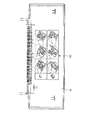
このようなインクジェットプリンタの外観を図1に示す。すなわち、本実施例におけるインクジェットプリンタ11は、上ケース12と下ケース13との間に開閉可能な操作カバー14を具えており、図2に示すように、操作カバー14を開けた状態に保持することができるようになっている。この操作カバー14の内側面には、この部分を抽出し拡大した図3に示すように、このインクジェットプリンタ11の操作説明を描いたイラストレーション15がレーザー刻印されており、このレーザー刻印部分を含む操作カバー14が本実施例における再生プラスチック材料の原料として採用される。
【0093】
本実施例における再生システムの概略構成を図4に示す。すなわち、再生プラスチック材料となる原料は、粉砕機101により所定の大きさに粉砕され、粉砕された原料は搬送装置102によって所定量ずつ振動篩103に送られ、後の作業で目詰まりなどの支障をきたす微粉末を廃棄タンク104に排出すると共に充分に粉砕されていない原料を回収タンク105に回収し、これを再度粉砕機101に戻す一方、所定の大きさに粉砕された原料を磁気分別機106に通して原料中に含まれる強磁性の金属を捕捉したのち、スクリューフィーダ107のホッパ108に供給する。スクリューフィーダ107は、モータ109により駆動されて洗浄液タンク110内に原料を所定量ずつ供給する。
【0094】
本実施例における洗浄液タンク110の概略構造を図5に示す。すなわち、本実施例における洗浄液タンク110は複数槽に仕切られ、金属やその他の異物との比重差を利用して再生原料となるプラスチックを分離するものであり、最終槽111内に流れ込む原料をモータ112によって駆動される洗浄脱水装置113で脱水し、空送ブロワ114によりサイクロン115に供給される。
【0095】
洗浄液タンク110の溢流堰116から溢流する洗浄液Wは、バッファタンク117から蒸留濃縮装置118に送られ、この蒸留濃縮装置118によって清浄化された洗浄液が凝縮液タンク119に送給され、再び洗浄液タンク110に戻される。また、蒸留濃縮装置118によって濃縮されたインクなどで着色状態の残液が濃縮液タンク120に排出される。
【0096】
なお、溢流堰116から溢流した洗浄液Wの一部は、フィルタ121を介してスクリューフィーダ107内にも少しずつ供給され、このスクリューフィーダ107内で原料を移動させる際の潤滑剤として利用している。
【0097】
前記サイクロン115に供給された原料は、ここで風力分級され、ロータリ弁122により所定量ずつアスピレータ123側に投下され、再生プラスチック材料となる原料に対して嵩比重の小さな発泡ポリウレタン樹脂(後述するカートリッジに収容されてインク保持部材として機能する)などがブロワ124により回収タンク125に排出される。
【0098】
アスピレータ123から流下する金属粉などの付着した原料は、再度磁気選別機126に通され、表面に付着している強磁性の金属粉が捕捉分離され、空送ブロワ127によりスクリューフィーダ128のストックタンク129に供給され、モータ130により駆動されるスクリューフィーダ128によって所定量ずつ渦電流などを利用して原料から金属を分離するための金属分離装置131に送られ、この金属分離装置131によって原料中に含まれる金属粉などが分離され、金属粉は回収タンク132に排出される。
【0099】
金属分離装置131により分離された原料は、ブロワ133によってホッパ134に投下され、最終的な再生プラスチック材料として回収容器135に回収される。
(第1の実施例)
図6に示すようなインクジェットプリンタ(キヤノン(株)製:BJC-430J)の操作カバー19(材質:ABS樹脂,平均肉厚2.5mm,真密度1.05)に対し、図7に示すような操作説明のイラストレーション20をレーザー刻印した原料を約40kg作製した。このABS樹脂には、強度,摺動性,難燃性などの特性を付与する充填剤や強化材は含まれておらず、また銘板などの異取材の貼り付けも行われていない。
【0100】
ここで使用したレーザー刻印機は、SMU65DT10DK(ドイツ国 BAASEL LASERTECH社製)であり、仕様はレーザ光源:Nd:YAGレーザ、波長1.064μm、出力65W、ターンテーブルの直径が1000mm、レンズの焦点距離が254mmで、刻印ヘッドは最大刻印領域が230mmの径のものを2個装備している。さらに、レーザー刻印時に発生するヒュームを除去するために、フィルタ付きの排気ポンプを備えている。
【0101】
この排気ポンプのノズルを可能な限りレーザー照射位置に近づけることにより、発生したヒュームが操作カバー19の刻印面に再度付着して刻印部分の品質を落とすことのないように配慮している。
【0102】
レーザーの一走査の線幅は視認性から決まる要素である。例えば、30cm離れた位置から、白色系のプラスチック材料にレーザー刻印された文字を視認する場合、線幅は0.3mmもあれば充分である。ところが、特に電子機器の操作説明など刻印内容に図7に示すようなイラストレーション20が含まれている場合、繰り返しの走査線が密集する画像部分と文字部分とでは、同じ条件で刻印すると画像部分の刻印が深くなり、更に刻印部分周囲の樹脂の盛り上がりも大きくなって輪郭も崩れ、結果として視認性を落としてしまう。従って、同じ深さで、複数回に分けて、少しづつずらしながら刻印することにより、溶融部分のバランスを保つ必要がある。
【0103】
また線幅が太いと、レーザーのエネルギーにより再生プラスチック材料に対する異物となり得る変色物あるいは炭化物そのものの量が増えるという問題があり、視認性と変色物あるいは炭化物の量とのバランスの上で成り立つ系を考慮する必要がある。
【0104】
一方、刻印の深さは深いほど表面とのコントラストが生ずるため、視認性は向上するが、リサイクル時は刻印部分が深いほど洗浄が行いにくく、異物が残る可能性が高まる。刻印部分に洗浄液を充分に行き渡らせるためには、走査線の断面が半円になるように設定することが好ましい。すなわち、線幅に対する刻印深さは1/2以下に保つことが好ましい。
【0105】
レーザー刻印機は刻印ヘッドの走査速度が可変のものが多い。刻印の線幅および深さはレーザーのエネルギー量と刻印ヘッドの走査速度とにより最適値に調整することができ、これによって画像部分と文字部分との刻印の視認性を同等に保つことができる。
【0106】
走査速度の設定は、使用するレーザー刻印機のエネルギー量にも左右されるが、上記要素を考慮して検討した結果、視認性と変色物あるいは炭化物の量の発生を抑制するためには、レーザーの一走査の線幅を0.2mm以下、深さを0.1mm以下に保つことが好ましい。
【0107】
異種材質に対する相溶性を評価する場合、例えば基準となる物質Aにある物質Bを重量比C%混入して物性値を測定し、物質Aと同等の物性値を示すと物質Bは物質Aに対し相溶性があると評価される。上市(第三者に利用できるようにすること:placing on the market)されている相溶性ラベルの評価においては、C=1%が一般的に取り扱われている。
【0108】
レーザーによる刻印は表面的なものであるから、刻印される材料の厚さを考慮し上記重量比を表面積比に置き換える必要がある。
【0109】
熱可塑性プラスチックの中でもリサイクルに適しているといわれるのは補強材や充填剤を含まないものである。このうち、ABS樹脂,PS樹脂,PS変性PPE樹脂においては、射出成形における金型からの転写性を考慮した場合、製品の肉厚はガスアシスト成形などの特殊成形を除くと3.0mm以下に保つのがよいとされている。また、電気電子機器製品において、製品としての耐荷重(強度)を考慮した場合、別部材による補強がない場合には肉厚は概ね2.0mm以上必要である。
【0110】
したがって、レーザ刻印の面積は、被刻印プラスチック部品の肉厚tmmに応じて表面積のt%以下にするとよく、電気電子機器製品においては少なくとも3.0%以下にするとよい。
【0111】
あるいはレーザー刻印の一走査の線幅を0.2mm以下にし、あるいはレーザー刻印の深さを0.1mm以下にすることがこれを再生プラスチック材料として利用する上で望ましい。
【0112】
ここで、製品の肉厚,レーザーのエネルギー量,刻印部分周囲の盛り上がりを含む視認性,生産性(レーザー刻印に要するタクトタイム、つまり照射時間)などを考慮すると、レーザー刻印は、最適には表面積の3%以下,一走査の線幅が0.15mm以下,刻印深さが0.05mm以下であることが好ましい。
【0113】
本実施例において、照射されたレーザーにより刻印された1本の線の照射面における太さは0.12mm,照射面からの深さは0.05mmであり、刻印面積は約920mm2であった 。上述した操作カバー19の表面積は686cm2であり、レーザー刻印部分の占める面積比は1.34%であった。レーザーの熱による炭化物の盛り上がりは上記線の太さや深さの計測には含まれていない。
【0114】
刻印部の視認性をさらに高めるため、本実施例におけるレーザー刻印に用いた加工データは、操作カバーなどに通常用いられる印刷版下に一部変更を施している。例えば、2本の線が重なる箇所は、片側の線を寸断してレーザーによる溶解部のバランスを全体に均一に保つようにしている。
【0115】
この操作カバーを、図4に示す粉砕機101(森田精機(株)製:JC-10)に6mmメッシュスクリーンを取り付けて粉砕した。
【0116】
生成した粉砕物を洗浄・洗浄液除去装置((株)東洋整機製:ハイチップクリーナCFP-500,図4の110,113に相当する)を用いて洗浄および洗浄液除去を行った。この時のプラスチック投入速度は、毎分2.5kg、洗浄液W(水道水を使用)の流量は毎分80リットルであった。洗浄液Wは、図5に示すような2000リットルの容量を持つ洗浄液タンク110で受け、図示しないポンプにて循環再使用するためにナイロンモノフィラメント((株)ロフラー製:バグフィルタR100NMO12M,濾過精度100μm)をフィルタハウジング(同社製:EBF112S6M)に収容して濾過した。
【0117】
洗浄および洗浄液除去を行った粉砕物は、空送ブロワ114((株)ホーライ製:DF-5)にて、風力分別アスピレータシステム((株)ホーライ製:KF-12,図4中の123に相当する)に送り、軽嵩密度の異物とその他の粉砕物に分別される。
【0118】
風力分別アスピレータシステムを通過した粉砕物は、磁気選別機126((株)JMI製:マジックキャッチ,残留磁束密度1.3テスラ)上に投下され、強磁性体成分を分別した。
【0119】
続いて空送ブロワ127((株)ホーライ製:DF-1)にてストックタンク129に粉砕物を搬送する。このストックタンク129から毎分約3kgの割合で渦電流式金属検知除去装置(センサーテクノロジー(株)製:MDS-30A,図4中の131に相当する)へ定量搬送し、金属分を除去分別した。最終的に得られた洗浄済み粉砕材は38kgであった。
【0120】
得られた洗浄済み粉砕材に付着している水分量は重量法により測定し、0.11重量%であった。さらに残留している金属分は目視ではゼロになっていた。
【0121】
この洗浄済み粉砕材のみをペレット化し、これを用いてアイゾット衝撃試験用サンプル片(ASTM-D256準拠:1/4インチノッチ付き)を5本作成し、アイゾット衝撃強度を測定した。
【0122】
ペレット化工程は、押出機(日本プラコン社製:DMG40mm)に60メッシュのフィルタを取りつけ、シリンダ温度210℃で溶融、混練、押し出しを行なった。アイゾット衝撃試験用サンプル片は、ペレット化した上記粉砕材を用い、射出成形機(東芝機械製:IS−80G)にASTM試験片用ファミリー金型をセットし、シリンダ温度200℃で射出成形して作成した。
【0123】
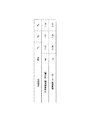
また、このサンプル片に対して、ヴァージンペレットにて作成したアイゾット衝撃試験用サンプル片を色差標準として色差測定(JIS-Z8722条件D準拠)を行った。同様に、MFR(JIS-K7210準拠:220℃,荷重98.07N)も5回測定した。結果は、図13中のS1に示す。
【0124】
なお、図13における色差ΔEab*は、JIS−K7105に規定されているように、以下のような式により計算される。
【0125】
ΔEab*=[(ΔL*)2+(Δa*)2+(Δb*)2]1/2
また、上記のメルトフローレート(Melt Flow Rate)は、JIS−K7210B法に準拠して測定した。この方法は、規定する温度と圧力条件の下で、溶融した熱可塑性プラスチックを規定の長さと直径のダイ(賦形用口金を伴う金属ブロック)を通して押し出したときの押出速度を測定するものであり、その内B法は、MFRが10分間あたり、0.50〜300gの材料に適用される自動時間測定方法である。
【0126】
試験装置は、テクノセブン製全自動メルトインデクサー(270型)を使用し、ダイ(樹脂押し出し部)は、長さ8.0137±0.025mm、内径はφ2.092±0.002mmである。
【0127】
この試験装置に、80℃×2時間の条件で乾燥した試料(樹脂)を1回あたり7g充填した。温度220℃で6分間予熱した後、同じく試験温度220℃、試験荷重98.07N(10kgf)で試料を押し出した。このときのピストンが25.0mm(Lとする)移動する間の時間t秒を計測し、以下によりMFRを算出した。
【0128】
なお、試験温度における樹脂の溶融密度ρは、0.953g/cm3であった。
【0129】

【0130】
図13から明らかなように、RVからR1へはアイゾット衝撃値が6.3%,MFRが2.9%、それぞれ減少している。また、RVからS1へはアイゾット衝撃値が12.5%(R1に対して6.7%)減少しているのに対し、MFRは0.6%(R1に対して3.6%)増加している。再生プラスチック材料にヴァージン材と同等の性能を持たせるため、アイゾット衝撃強度RVが0.8倍以内であってMFRが1.2倍より小さい必要があるので、その点から鑑みると、上記物性値の変化率は、再生プラスチック材料としての特性を充分に満足しているといえる。
【0131】
色差については、ヴァージンペレット状態での色差ばらつきから考慮した。ABS樹脂の場合、特にΔb*に影響する色味のばらつきが大きく、Δb*≦1.0であればヴァージン材と同じ工程で補色が可能である。従って、ΔEab*=0.88はΔb*=0.79の成分がほとんどのため、ヴァージン材に対して同等の扱いをすることができる。
【0132】
残留水分も0.11重量%であり、加水分解性に起因するプラスチックへの悪影響を防ぐことができた。
【0133】
図1〜図3に示すインクジェットプリンタ11(キヤノン(株)製:BJF-600)は、現在、すべてのプラスチック部品がヴァージン材で形成され、生産および販売されており、このインクジェットプリンタ11を上述の再生工程を経て得られた洗浄済み粉砕材を用いて作製した。具体的には上ケース12(平均肉厚2mm,重量389g)、下ケース13(平均肉厚2mm,重量545g)、操作カバー14(平均肉厚2.3mm,重量159g)にそれぞれ適用した。図3は、この操作カバー14に操作説明のためのイラストレーション15をレーザー刻印した状態を示す。
【0134】
これら3つの部品において外観および色彩(色相,彩度,明度)ともにヴァージン材を用いて製造されたものと目視で差が認められなかった。
【0135】
この操作カバー14を含むBJF-600の外装表面積は4920cm2であり、これに対してレーザー刻印部分の表面積は920mm2で、外装表面積に対するレーザー刻印の面積比は0.187%である。上述の実証実験で行った場合に対し、レーザー刻印部分の面積比は1.34%から0.187%へ小さくなっている。さらに、印字済の用紙を保持するトレイ21も同プラスチック材料を用いて作成しており、また、リサイクル工程でこの操作カバー14だけを別工程で再生する必要はなく、工数上からも考えにくい。
【0136】
従って、このインクジェットプリンタ11の外装部材12〜14を用いて作製された再生プラスチック材料の物性値は、前述の再生工程で得られた物性値以上によりヴァージン材に近い物性値を示すことが期待できる。
(第1の実施例の比較例)
第1の実施例に対し、レーザー刻印の表示内容をPS樹脂製のラベル(厚さ150μm)に印刷し、操作カバー19に貼り付け、これ以外は同一の工程で熱可塑性プラスチックの再生を行った。貼り付けたラベルの面積は186.2cm2であり、操作カバー19に対する重量比は約3%であった。
【0137】
この洗浄済み粉砕材の物性値は、ヴァージンペレットと同一条件での測定においてアイゾット衝撃値が97.1J/m,MFRが53.7g/10min.,色差ΔEが1.03であった。測定した物性値は、図13中のC1に示す。
【0138】
図13に示すように、RVからC1へはアイゾット衝撃値が38.1%減少し、MFRは10.0%増加している。前述のように、ヴァージン材と同等の性能を得るためにアイゾット衝撃強度を0.8倍以内にすると共にMFRを1.2倍より小さする必要があるので、レーザー刻印に代えて印刷によりイラストレーションを形成したPS樹脂製ラベルが貼付された操作カバー19から得られる再生プラスチック材料は、要求される特性を満足するものではない。また、色差も1.0を上回っており、ヴァージン材と比較して品質が低下していることが理解できよう。
【0139】
上述した実施例では、再生プラスチック材料としてインクジェットプリンタの外装部材を対象としたが、上述したインクジェットプリンタのカートリッジに対して応用した場合について説明する。
【0140】
本実施例の対象となったカートリッジの外観を図8に示し、その分解状態を図9に示す。すなわち、本実施例におけるカートリッジ31は、熱エネルギーを利用してインクを吐出するインクジェット式のプリントヘッド32とインクタンク33とを一体化したものであり、上述した種類のインクジェットプリンタに対して交換可能に搭載される。
【0141】
このカートリッジ31のプリントヘッド32はエッチング,蒸着,スパッタリングなどの半導体製造プロセスを経て、基板上に成膜された電気熱変換体,電極,液路壁、天板などを有する。
【0142】
ヒータボード34は、シリコン基板上に、電気熱変換素子とこれに電力を供給するアルミニウムなどの配線とを成膜技術により形成した構造を有する。35はヒータボード34に対する配線基板であり、対応する配線は例えばワイヤボンディングにより接続される。36はインク流路を限界するための隔壁や共通インク室などを形成した天板であり、本実施例では、吐出口板部を一体に有する熱可塑性プラスチックで形成されている。
【0143】
37は金属製のベースプレート、38はSUS製の押さえばねであり、両者間にヒータボード34および天板36を挟み込んだ状態でこれらを結合することにより、押さえばね38の付勢力によりヒータボード34と天板36とが圧着固定される。なお、ベースプレート37は、配線基板35が貼着などにより固定され、また、インクを吐出する際に生じるヒータボード34の熱を放熱冷却するための部材としても機能する。
【0144】
39はサブタンクであり、インク供給源であるインクタンク33からインク供給を受け、ヒータボード34と天板36との接合により形成される共通液室に対し、プラスチック成形された供給管40を介してインクを導くためのものである。41は共通液室へのインク供給口付近のサブタンク39内の部位に配置されるSUS製のフィルタであり、プラスチック成形体のフィルタ固定部材42により取り付けられる。43はその爪部43aの部分がサブタンク39に形成されたボス部39aに溶着されるカバー板であり、プラスチック成形体である。44はインクを含浸させるための発泡ポリウレタン樹脂製のインク保持部材であり、インクタンク33内に配置される。45は上記構成部品34〜43からなる吐出ユニットに対してインクを供給するための供給口であり、この吐出ユニットをインクタンク33に配置する前の工程で、供給口45からインクを注入することによりインク保持部材44のインク含浸を行わせることができる。46はインクタンク33の蓋部材、47はカートリッジ31内部を大気に連通するための大気連通口である。
【0145】
なお、このようなカートリッジ31のインクタンク33内に収容されるインクとしては、特公平7−119378号公報に開示されているようなものが知られており、色剤として染料を用いたものの他に、顔料などを使用したものも周知である。
(第2の実施例)
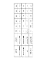
図8,図9に示したカートリッジ31(キヤノン(株)製:BC-02)の使用済みのものを2000個集め、これらをまず図10に示すようにインクタンク33からカバー板43の部分と、プリントヘッド32,配線基板,ベースプレート37とを取り外し、さらに二点鎖線で示す切断線Lの部分からインクタンク33を切断し、図11に示すようにインクタンク33内に収納されていたインク保持部材44を取り出し、インクタンク33の外装部材(材質:PS変性PPE,真密度1.08)を再生原料として約30kg得た。このプラスチックは全て同一ロットより作製されており、使用前のヴァージンペレットの状態での物性値は、アイゾット衝撃試験値(ASTM-D256準拠:サンプルサイズ2.5×0.5×0.25(インチ),モールドノッチ付き)は90.2J/mであり、MFR(ASTM-D1238準拠:250℃,荷重98.07N)は44g/10min.であった。測定した物性値を図14中のR2に示す。
【0146】
ただし、色差はJIS-Z8722条件Dに準拠して求めた三刺激値をJIS-K7105に基づく色差式により算出した。
【0147】
このカートリッジ31を構成する材料のうち、外装部材以外の材料としてはインク吐出口の目詰まりを防ぐためのフィルタ41であるステンレスの他、PP,PTFE,ガラスなどが用いられ、シール材として各種ゴムや金属、インク保持部材44としての発泡ポリウレタン樹脂や多孔質成形体、さらにインクそのものなどがある。さらに、プリントヘッド32を構成する材料としてガラスエポキシ基板,アルミニウム基板,配線材としての金・銅,図示しない吐出口板としてスーパーエンジニアリングプラスチックなどが用いられている。
【0148】
この使用済み外装部材を図4に示す粉砕機101((株)ホーライ製:VC-210)に8mmのメッシュスクリーンを取り付けて粉砕した。このプラスチック粉砕物には、インクおよびその組成物が平均して1200ppm付着しており、分別し切れていないカートリッジ31を構成するSUS製のフィルタ41や鋼球(真密度:7.9)などの金属類が200ppm程度,切断屑としてのインク保持部材44(嵩密度:0.041)が400ppm程度混入していた(何れも目視で分別後、重量法によって求めた)。
【0149】
この粉砕物を洗浄・洗浄液除去装置((株)東洋整機製:ハイチップクリーナCFP-500)を用いて洗浄・洗浄液除去を行った。この時のプラスチック投入速度は毎分2.5kg,洗浄液(本実施例では水道水)の流量は毎分80リットルであり、洗浄液と原料との単位時間当たりの投入量の重量比は32/1であった。洗浄液は、図5に示すような2000リットルの容量の洗浄液タンク110で受け、これを汲み上げて再使用する前にナイロンモノフィラメント((株)ロフラー製:R100NMO12M)をフィルタハウジング(同社製:EBF112S6M)に収容したものを用いて濾過した。
【0150】
洗浄および洗浄液除去を行った粉砕物は、空送ブロワ114((株)ホーライ製:DF-5)にて、風力分別アスピレータシステム((株)ホーライ製:KF-12)に送り、軽嵩密度のインク保持部材44とその他の粉砕物とに分別した。
【0151】
風力分別アスピレータシステムを通過した粉砕物は、磁気選別機126((株)JMI製:マジックキャッチ,残留磁束密度1.3テスラ)上に投下され、強磁性体成分を分別した。
【0152】
続いて空送ブロワ127((株)ホーライ製:DF-1)にてストックタンク129に粉砕物を供給する。このストックタンク129から毎分約3kgの割合で渦電流式金属検知除去装置(センサーテクノロジー(株)製:MDS-30A)へ定量搬送し、金属分を除去分別した。最終的に得られた洗浄済み粉砕材は28kgであった。
【0153】
得られた洗浄済み粉砕材に付着している水分量,インク量はそれぞれ重量法,比色分光法により測定した結果、それぞれ0.1重量%,90ppmであった。さらに残留している金属分,発泡ポリウレタン樹脂などは目視ではゼロであった。
【0146】
この洗浄済み粉砕材のみを用いてアイゾット衝撃試験用サンプル(ASTM-D256準拠:サンプルサイズ2.5×0.5×0.25(インチ),モールドノッチ付き)を5本作製し、アイゾット衝撃強度を測定した結果の平均値は、89.2J/mであった。
【0154】
このサンプル片に対して、ヴァージンペレットにてアイゾット衝撃試験用サンプルを成型したサンプルを色差標準として色差測定をした結果は、ΔEが0.43であった。また同様に、MFR(ASTM-D1238準拠:250℃,荷重:98.07N)を3回測定し、その平均値は42g/10min.であった。測定した物性値は、図14中のS2に示す。
【0155】
図14に示すように、R2からS2へはアイゾット衝撃値は1.1%,MFRは4.5%、それぞれ減少している。再生プラスチック材料をヴァージン材と同等の性能を持たせるため、アイゾット衝撃強度を0.8倍以内に収めると共にMFRを1.2倍より小さくする必要があるが、上記物性値の変化率は、再生プラスチック材料としての特性を充分に満足しているといえる。
【0156】
色差については、ヴァージンペレット状態での色差のばらつきから考慮した。PS変性PPE樹脂の場合、ΔE≦1.0を目標としたが、ΔEが0.43という結果からヴァージン材と同等に扱うことが可能である。
【0157】
残留水分量は0.10重量%であり、加水分解性に起因する再生プラスチック材料ヘの悪影響を防ぐことができた。残留インク量は90ppmであり、これらの結果から本実施例によって製造される再生プラスチック材料は、ヴァージン材と同等に扱えるものであると判断できる。
【0158】
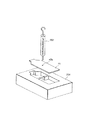
更なる特性の確認として、この洗浄済み粉砕材のみを用い、カートリッジ31のカバー板43を100枚成型した。これとは別にヴァージンペレットにて同じ比較試料を100枚成型した。このなかより無作為に選んだ10枚ずつを図12に示す専用治具201に取り付け、カバー板43の爪部43aの破壊強度をプッシュプルゲージ202を用いて測定した結果を図15中のS2に示す。
【0159】
図15のS2に示す爪部43aの破壊強度は3.1%増加しており、曲げ強さ、靭性ともヴァージン材と同等性能といえる。
(第2の実施例の比較例)
洗浄後に行った熱可塑性プラスチック以外の金属などの固形物(以下、異物とも呼称する)の分離効果を確認するため、風力分別アスピレータシステム((株)ホーライ製:KF-12)および電流式金属検知除去装置(センサーテクノロジー(株)製:MDS-30A)の電源を切り、嵩密度差を利用した風力分級および渦電流を利用した金属分離を行わない以外は、上記第2の実施例と同一の再生工程により原料の再生処理を行った。
【0160】
投入したカートリッジ31におけるインクタンク33の外装部材約30kgに対し、結果として得られた洗浄済み粉砕材は28kgであり、含まれる金属分は100ppmであった(重量法により測定)。また、この洗浄済み粉砕材の物性値は、アイゾット衝撃試験値が66.6J/m,MFRが56g/10min.,色差ΔEが0.60であった。測定した物性値は、図14中のC2に示す。
【0161】
図14から明らかなように、R2からC2へはアイゾット衝撃値は26.2%減少し、MFRは27.3%増加しており、アイゾット衝撃強度が0.8倍を越え、かつMFRが1.2倍以上であった。また、残留水分は0.25重量%であって0.30重量%を下回っているものの、残留金属量は100ppmもあった。結果として、ヴァージン材と同等の性能を持つ再生プラスチック材料に関して、風力分級および金属分離の効果を確認することができた。
(第3の実施例)
第2の実施例における粉砕時のメッシュスクリーンとして6mmのものを使用し、洗浄時にプラスチック投入速度を毎分8kg、洗浄液の流量を毎分80リットルにする以外は同様の洗浄,洗浄液除去,乾燥,精密分別処理を行った結果、得られた洗浄済み粉砕材は27kgであった。
【0162】
この洗浄済み粉砕材の物性値は、アイゾット衝撃験値が87.2J/m,MFRが43g/10min.,色差ΔEが0.49であった。残留水分量などと合せ、測定した物性値は図14中のS3に示す。
【0163】
図14から明らかなように、R2からS3へはアイゾット衝撃値が3.3%減少し、MFRは2.2%増加している。前述のように、再生プラスチック材料に対してヴァージン材と同等の性能を考慮した場合、アイゾット衝撃強度を0.8倍以内に収めると共にMFRを1.2倍より小さいする必要があるが、上記物性値の変化率は、再生プラスチック材料としての特性を充分に満足しているといえる。
【0164】
また、色差ΔEが0.49,残留水分量が0.15重量%であり、ともにヴァージン材と同等性能を得るに充分な数値を得ることができた。さらに、残留インク量は150ppmであるが、測定した他の物性値および色差を考慮すると、ヴァージン材と同等に扱える品質にあると判断できる。
【0165】
更なる特性の確認として、この洗浄済み粉砕材のみを用い、カートリッジ31のカバー板43を100枚成型し、この中から無作為に選んだ10枚を図12に示す専用治具201に取り付け、カバー板43の爪部43aの破壊強度をプッシュプルゲージ202を用いて測定した結果を図15中のS3に示す。
【0166】
図15に示す爪部の破壊強度は、1.2%増加しており、曲げ強さおよび靱性共にヴァージン材と同等性能であることを確認できた。
(第4の実施例)
図6に示すインクジェットプリンタ(キヤノン(株)製:BJC-430)の使用済み製品を40台集め、前カバー17,後ろカバー18,操作カバー19からなる外装部材(何れもABS樹脂:真密度1.05)を約40kg得た。操作カバー19の前面に貼着されている製品銘板や後ろカバー18の底面から突出するゴム脚部などは予め分離除去した。
【0167】
使用したABS樹脂のヴァージンペレットの状態での物性値は、アイゾット衝撃試験値(ASTM-D256準拠:1/8インチノッチ付き)は157.8J/m、MFR(JIS-K7210準拠:220℃,荷重98.07N)は40.7g/10min.であった。このプラスチック粉砕物には、インクおよびその組成物が最大で700ppm程付着していた(付着インクおよびその組成物の量は比色分光法により測定した)。また、分別し切れていない金属類やインク保持部材は、目視上で混入していなかった。測定した物性値は、図16中のR4に示す。
【0168】
ただし、色差はJIS-Z8722条件Dに準拠して求めた三刺激値をJIS-K7105に基づく色差式により算出した。
【0169】
この使用済み外装部材を、図4に示す粉砕機101(森田精機(株)製:JC-10)に6mmのメッシュスクリーンを取り付けて粉砕した。
【0170】
この粉砕物を洗浄・洗浄液除去装置((株)東洋整機製:ハイチップクリーナーCGP-500)を用いて洗浄および洗浄液除去を行った。この時のプラスチック投入速度は毎分2.5kg,洗浄液(本実施例では水道水)の流量は毎分80リットルであった。洗浄水は、図5に示すような2000リットルの容量の洗浄液タンク110で受け、これを汲み上げて再使用する前にナイロンモノフィラメント((株)ロフラー製:バグフィルタR100NMO12M,濾過精度100μm)をフィルタハウジング(同社製:EBF12S6M)に収容したものを使用して濾過した。
【0171】
洗浄および洗浄液除去を行った粉砕物は、空送ブロワ114((株)ホーライ製:DF-5)にて、風力分別アスピレータシステム((株)ホーライ製:KF-12)に送り、軽嵩密度の発泡ポリウレタン樹脂などの異物とその他の粉砕物とに分別される。
【0172】
風力分別アスピレータシステムを通過した粉砕物は、磁気選別機126((株)JMI製:マジックキャッチ,残留磁束密度1.3テスラ)上に投下され、強磁性の金属を分別した。
【0173】
続いて空送ブロワ127((株)ホーライ製:DF-1)にてストックタンク129に粉砕物を搬送する。このストックタンク129から毎分約3kgの割合で渦電流式金属検知除去装置(センサーテクノロジー(株)製:MDS-30A)へ定量供給し、金属分を除去分別した。最終的に得られた洗浄済み粉砕材は38kgであった。
【0174】
得られた洗浄済み粉砕材に付着している水分量,インク量はそれぞれ重量法,比色分光法によって測定した結果、それぞれ0.11重量%,10ppmであった。さらに、残留している金属分は目視ではゼロであった。
【0175】
この洗浄済み粉砕材の物性値は、ヴァージンペレットと同一条件で測定においてアイゾット衝撃値が145.0J/m,MFRが42.0g/10min.,色差ΔEが0.35であった。測定した物性値を図16中のS4に示す。
【0176】
図16に示すように、R4からS4へはアイゾット衝撃値は8.1%減少し、MFRは3.2%増加している。再生プラスチック材料をヴァージン材と同等の性能にするためには、アイゾット衝撃強度を0.8倍以内に収めると共にMFRを1.2倍より小さくする必要があり、その点から鑑みると、上記物性値の変化率は、再生プラスチック材料としての特性を充分に満足しているといえる。
【0177】
色差については、ヴァージンペレット状態での色差のばらつきから考慮した。ABS樹脂の場合、ΔE≦1.0を目標としたが、得られた色差ΔEが0.35であるので、ヴァージン材と同等に扱えることが判明した。
【0178】
さらに、残留水分量は0.11重量%であり、加水分解性に起因するプラスチックへの悪影響を防ぐことができた。残留インク量は10ppmであり、この結果、本実施例にて製造された再生プラスチック材料は、すべての点においてヴァージン材と同等に扱える品質を有していると判断できた。
【0179】
図1および図2に示すインクジェットプリンタ11(キヤノン(株)製:BJF-600)は、現在、すべてのプラスチック部品がヴァージン材で形成され、生産および販売されており、このインクジェットプリンタ11を上述の再生工程を経て得られた洗浄済み粉砕材を用いて作製した。具体的には上ケース12(平均肉厚2mm,重量389g)、下ケース13(平均肉厚2mm,重量545g)、操作カバー14(平均肉厚2.3mm,重量159g)にそれぞれ適用したところ、これら3つの部品12〜14において外観および色彩(色相,彩度,明度)ともヴァージン材を用いて作製されたものと目視で差が認められなかった。
(第4の実施例の比較例)
第4の実施例に対し、洗浄・洗浄液除去装置(図4の110,113に相当する)へのプラスチック投入速度を毎分2kg,洗浄水の流量を毎分10リットルに変更し、これ以外は同一の工程で原料の再生処理を行った結果、得られた洗浄済み粉砕材は27kgであった。
【0180】
この洗浄済み粉砕材の物性値は、ヴァージンペレットと同一条件での測定においてアイゾット衝撃値が121.5J/m,MFRが45g/10min.,色差ΔEが1.03であった。残留水分量などと合せ、測定した物性値は、図16のC41列に示す。
【0181】
図16に示すように、R4からC41へはアイゾット衝撃値が23.0%減少し、MFRは10.6%増加している。前述のように、再生プラスチック材料をヴァージン材と同等の性能にするためには、アイゾット衝撃強度を0.8倍以内に収めると共にMFRを1.2倍より小さくする必要があるが、洗浄液と粉砕材との重量比を変更して得られた再生プラスチック材料は、その必要な特性を満たしていないといえる。
【0182】
色差ΔEも1.03であって限界値の1.0を上回り、残留水分量が0.55重量%,残留インク量が340ppmであり、測定した他の特性値を合せ、ヴァージン材と比較して相対的に品質が低下していることがわかる。
(第4の実施例の比較例2)
第4の実施例に対し、洗浄液の濾過フィルタの濾過精度を250μmに変更し、これ以外は同一の工程で原料の再生処理を行った。
【0183】
この洗浄済み粉砕材の物性値は、ヴァージンペレットと同一条件での測定においてアイゾット衝撃値が117.7J/m,MFRが52g/10min.,色差ΔEが1.16であった。測定した物性値は、図16中のC42に示す。
【0184】
図16に示すように、R4からC42へはアイゾット衝撃値は25.4%減少し、MFRは27.7%増加している。前述のように、再生プラスチック材料をヴァージン材と同等の性能にするためには、アイゾット衝撃強度を0.8倍以内に収めると共にMFRを1.2倍より小さくする必要があるが、濾過フィルタの濾過精度を250μmに変更して得られた再生プラスチック材料は、その必要な特性を満たしていないといえる。
【0185】
また、色差ΔEが1.16であって限界値の1.0を上回っており、ヴァージン材と比較して品質が低下していることがわかる。
【0186】
(第5の実施例)
上述した実施例では、各実施例に係わるプラスチック材料の再生工程を一度経て得た再生プラスチック材料について、その物性値がヴァージン材と同等性能であるとしたが、この第5の実施例では、複数回の再生工程を行なった場合の物性について説明する。
【0187】
第4の実施例と同一の工程で熱可塑性プラスチック(ABS樹脂、真密度:1.05)の再生を行なった。ヴァージンペレットでの物性値は図17のR5に示す。また、第4の実施例と同一の再生工程を1回経た後に得られた洗浄済み粉砕材を再ペレット化した再生プラスチック材(以下、「1回再生材」と呼ぶ)の物性値を同じく図17のS51に示す。
【0188】
このようにして得られた、1回再生材を、再度ペレット化して得られた再生プラスチック材(以下、「2回再生材」と呼ぶ)の物性値を同じく図17のS52に示す。同様に再ペレット化を繰り返して得られた3回再生材、5回再生材の物性値をそれぞれ図17のS53、S55に示す。
【0189】
図17に示すようにヴァージン材(R5)に対し、本発明にかかる再生工程を経て得た1回再生材(S51)は、アイゾット衝撃値が2.3%減少し、MFRも2.3%減少している。色差も0.22に留まっており、いずれの数値も第4の実施例と同様と扱うことができ、即ち1回再生材はヴァージン材と同等に扱えることが分かった。
【0190】
同じように、2回、3回、5回再生材について、ヴァージン材(R5)に対する各物性値が低下(劣化)した場合で判定すると、いずれの物性値もS55が最も低下が著しく、アイゾット衝撃値で7.2%の減少、MFRで2.3%の増加、色差で0.51の低下が測定された。
【0191】
これらの数値は、0.8倍以内のアイゾット衝撃強度、1.2倍より小さいMFR値、色差1.0以内という、ヴァージン材と同等の性能を有する再生プラスチック材という本発明での定義に照らし合すと、いずれの物性値からもこの再生プラスチック材はヴァージン材と同等に扱えることが分かる。
【0192】
また、ロックウェル硬さはいずれの再生材もヴァージン材と略同一の値であり、この物性値からも再生プラスチック材の物性値が規定値内に保たれていることが分かる。
【0193】
即ち、複数回の再生工程を経た場合においても、本発明は有効であることが分かる。
【0194】
【発明の効果】
本発明によると、再生プラスチック材料の原料として、レーザー刻印された熱可塑性プラスチックを用いるようにしたので、再生プラスチック材料の再生工程において、ラベルの剥離工程が不要であり、またシルクスクリーン印刷などに用いられる塗料の付着もないため、再生工程を簡略化することができ、得られる再生プラスチック材料の色相劣化を防止することが可能である。
【0195】
また、レーザー刻印された熱可塑性プラスチック部品を有する電子機器を分解し、分解した電子機器の熱可塑性プラスチック部品から得られる熱可塑性プラスチックを原料として、この電子機器の熱可塑性プラスチック部品を成型するようにしたので、理想的なリサイクルを行うことができる。
【0196】
再生プラスチック材料の原料として、金属を含む熱可塑性プラスチックを用いるようにしたので、原料である熱可塑性プラスチックに含まれる金属のみならず、再生工程において原料を粉砕する際に混入する可能性がある金属片などのほとんどを容易に除去することが可能となり、コンタミネーションが極めて少なく、外観品質の良好な再生プラスチックを得ることができる。
【0197】
再生プラスチック材料の原料として、インクジェット装置に用いられた熱可塑性プラスチックを用いたり、インクまたはその組成物が付着した熱可塑性プラスチックを用いた場合には、これを元のインクジェット装置に用いられた熱可塑性プラスチック部品としてそのまま再利用することができる。
【0198】
上述した再生プラスチック材料を用いて電子機器を構成するようにしたので、その再生プラスチック材料の使用普及をより一層促進することができる。
【0199】
熱可塑性プラスチックを洗浄した後の洗浄液を25から200μmの範囲のメッシュを持ったフィルタで濾過し、濾過した洗浄液を再使用するようにした場合には、得られる再生プラスチック材料の物性と、フィルタの目詰まりとの両方の問題を解消することができる。
【0200】
洗浄液がpH濃度を調整するための添加剤および界面活性剤の少なくとも一方を含む場合、短時間の内に洗浄効果を得ることができる。
【0201】
洗浄液として水を使用し、洗浄後の水を濾過して再使用するようにした場合には、有機溶剤,界面活性剤,ビルダーなどを含む水性洗浄剤を用いた場合に比べて経済性,作業時の安全性を高めることができる。しかも、洗浄液を繰り返し再利用することにより、環境に対する負荷を最小限に抑えることができる。
【0202】
洗浄後の洗浄液を再利用する場合、フィルタによる異物除去に限らずpH濃度の調整などを一つのシステムにすることにより、再利用時の洗浄液の清浄性と環境負荷とを軽減することができる。
【0203】
再生プラスチック材料に対するインクまたはインク組成物の付着量を300ppm未満に制限することにより、再生プラスチック材料の色をヴァージン材を用いた場合と遜色ないものにすることができる。
【0204】
再生プラスチック材料のアイゾット衝撃値をIR、メルトフローレートをMRとし、成形加工前の熱可塑性プラスチックのヴァージン材のアイゾット衝撃値をIV、メルトフローレートをMVとした場合、(IR/IV)>0.8、かつ(MR/MV)<1.2を満たすようにした場合、再生プラスチック材料の品質をヴァージン材とほぼ同等に保つことができる。
【0205】
電子機器の外装部品を再生プラスチック材料で構成した場合、材料の物性値以上に、再生プラスチック材料を使用しても外観の商品性を落とすことがなく、従来のごとくサーマルリサイクルやカスケードリサイクルではない、再生材の使用用途を格段に広げることができる。
【0206】
インクジェット装置に用いられるインク収容容器の熱可塑性プラスチック部品から得られる熱可塑性プラスチックを原料とし、このインクジェット装置の熱可塑性プラスチック部品を成型するようにしたので、理想的なリサイクルを行うことができる。
【図面の簡単な説明】
【図1】本発明の対象となったインクジェットプリンタの外観を表す斜視図である。
【図2】図1に示したインクジェットプリンタの操作カバーを開いた状態を表す斜視図である。
【図3】図2に示した操作カバーの部分を抽出拡大した正面図である。
【図4】本発明による再生プラスチック材料の製造システムの一例を表す概念図である。
【図5】図4の製造システムに組み込まれた洗浄タンクの構造を表す断面図である。
【図6】本発明の対象となった別なインクジェットプリンタの外観を表す斜視図である。
【図7】図6に示したインクジェットプリンタの操作カバーの部分を抽出拡大した正面図である。
【図8】インクジェットプリンタに用いられるカートリッジの一例の外観を表す斜視図である。
【図9】図8に示したカートリッジの分解斜視図である。
【図10】図11と共に図8に示したカートリッジをリサイクルするための作業概念図であり、配線基板とカバー板とを取り外した状態を示す。
【図11】図10と共に図8に示したカートリッジをリサイクルするための手順を表す作業概念図であり、インクタンクを切断してインク保持部材を取り出した状態を示す。
【図12】図8,図9に示したカバー板に対する破壊強度試験をプッシュプルゲージを用いて行った場合の作業概念図である。
【図13】第1の実施例と比較例におけるプラスチック材料の物性値を示す図である。
【図14】第2の実施例とその比較例と、第2の実施例とにおけるプラスチック材料の物性値を示す図である。
【図15】第2の実施例と第3の実施例におけるプラスチック材料の物性値を示す図である。
【図16】第4の実施例と比較例におけるプラスチック材料の物性値を示す図である。
【図17】第5の実施例におけるプラスチック材料の物性値を示す図である。
【符号の説明】
11 インクジェットプリンタ
12 上ケース
13 下ケース
14 操作カバー
15 イラストレーション
16 インクジェットプリンタ
17 前カバー
18 後ろカバー
19 操作カバー
20 イラストレーション
21 トレイ
31 カートリッジ
32 プリントヘッド
33 インクタンク
34 ヒータボード
35 配線基板
36 天板
37 ベースプレート
38 押さえばね
39 サブタンク
40 供給管
41 フィルタ
42 フィルタ固定部材
43 カバー板
44 インク保持部材
45 供給口
46 蓋部材
47 大気連通口
101 粉砕機
102 搬送装置
103 振動篩
104 廃棄タンク
105 回収タンク
106 磁気分別機
107 スクリューフィーダ
108 ホッパ
109 モータ
110 洗浄液タンク
111 最終槽
112 モータ
113 洗浄脱水装置
114 空送ブロワ
115 サイクロン
116 溢流堰
117 バッファタンク
118 蒸留濃縮装置
119 凝縮液タンク
120 濃縮液タンク
121 フィルタ
122 ロータリ弁
123 アスピレータ
124 ブロワ
125 回収タンク
126 磁気選別機
127 空送ブロワ
128 スクリューフィーダ
129 ストックタンク
130 モータ
131 金属分離装置
132 回収タンク
133 ブロワ
134 ホッパ
135 回収容器
201 専用治具
202 プッシュプルゲージ
W 洗浄液[0001]
BACKGROUND OF THE INVENTION
The present invention relates to a recycled plastic material made from a thermoplastic product, an electronic device using the recycled plastic material, a method of manufacturing a plastic part, a method of manufacturing the recycled plastic material, and a method of reusing the plastic material.
[0002]
[Prior art]
In recent years, with the heightened awareness of environmental protection, movements such as recycling and recycling of petrochemical products in addition to metal materials that have been recycled have been increasing. Even in Japan alone, “Law on Waste Disposal and Cleaning” (Act No. 137 of 1971; commonly known as “Waste Cleaning Law”), “Separate collection and recycling related to containers and packaging, etc. Law "(Act No. 112 of 1995, commonly known as the" Container Packaging Recycling Law ")," Act on Recycling of Specified Household Appliances "(Act No. 97 of 1998, commonly known as the" Home Appliance Recycling Law ") With the development of these laws and regulations, the recycling of thermoplastics is being accelerated in some product groups such as large home appliances and automobiles.
[0003]
However, many of these recyclings are mainly thermal recycling using a thermoplastic plastic as a heat source, or recycling for cascade use in which the physical properties of the recycled thermoplastic plastic do not need to be much concerned. For this reason, most of electronic devices such as copiers, facsimiles, personal computers and peripheral devices (printers, keyboards, displays) and consumable parts (toner cartridges, ink cartridges, etc.) are included in the heat contained therein. Not much attention has been paid to the separation of plastics, and as a result, the thermoplastics that are recycled have a variety of contaminants and can be recycled into the very same products and parts. I couldn't get plastic.
[0004]
In addition, when manufacturing electronic devices and their components (hereinafter collectively referred to as electronic devices) with recycled thermoplastic plastics, they are mostly used as packaging containers and packaging materials. Moreover, the original electronic equipment was not constructed using recycled plastic materials. In particular, in the case of parts with labels, stickers, decals, etc. (hereinafter collectively referred to as labels) on which the operation instructions of the electronic equipment are printed, such as exterior parts of electronic equipment It is impossible to peel off the label base material and the pressure-sensitive adhesive only by washing operation, and it is necessary to remove the pressure-sensitive adhesive adhered to the parts with a cutter or the like.
[0005]
Similarly, desired character information or image information (hereinafter collectively referred to as image information) is printed by ejecting ink droplets from an ejection port onto an arbitrary print medium such as paper, fabric, plastic, or metal. In the case of electronic equipment with an ink holding member that holds ink typified by an inkjet device or a cartridge filled with ink, such as an electronic device in which an ink holding member is incorporated, recycle it as it is. However, deterioration of physical properties and hue change cannot be avoided due to the residual ink and its composition, and it is extremely difficult to recycle and recycle.
[0006]
Furthermore, since these ink jet devices contain not only ink but also contaminants such as lubricants (for example, grease) for mechanical drive parts, more complicated processes and regeneration costs are required than when plastic materials that can be normally considered are recycled. Therefore, until now, recycling using parts of the ink jet apparatus as raw materials has not been performed.
[0006]
As recycling methods in this field, JP-A-5-301222, JP-A-7-323560, Japanese Patent No. 2513106, and the like are disclosed. Among these, the technique disclosed in Japanese Patent Application Laid-Open No. 7-323560 only discloses a method for reusing a part to be recycled as it is by cleaning.
[0007]
In addition, the technique disclosed in Japanese Patent Laid-Open No. 5-301222 compensates for the decrease in the physical property value of the recycled plastic material by the additive. Moreover, the technique currently disclosed by the patent 2513106 supplements the fall of the physical-property value of recycled plastic material by polymer selection.
[0008]
On the other hand, a so-called laser marking technique is known as a method of changing the surface of a plastic part and displaying desired image information. According to this technology, it is possible to directly describe the operation explanation of the device on the part, and it is possible to reduce the cost and man-hour required for deleting the attached label. Details of this laser marking technique are described in Japanese Patent Publication No. Sho 61-11711 and Japanese Patent Publication No. Sho 62-59663, which disclose the basic technique of laser marking and have been laser stamped. It does not indicate specific measures for plastic recycling.
[0009]
[Problems to be solved by the invention]
When the physical properties of the material are taken into consideration, the range of use is greatly increased by guaranteeing the same physical property value as that of the virgin material even if it is a recycled material. However, when guaranteeing physical property values, adding additives and selecting polymers in the recycling process as in the above-described conventional technology increases factors that affect costs, such as management of the amount of additive added and polymer selection costs. As a result, there was a possibility that the use switching from the virgin material to the recycled material was postponed.
[0010]
Further, as a characteristic of the thermoplastic plastic, a line pattern such as a black stripe (silver streak) or a silver stripe (silver streak) may be generated on the surface of the molded product due to the influence of heat applied during molding. These are mainly caused by the molding conditions. When foreign materials are mixed in the material itself, black spots often appear on the surface.
[0011]
In the laser engraving for discoloring or carbonizing the surface of an object to be processed, when the object to be processed is a thermoplastic, the engraved portion can be a foreign substance as it is. Further, not only laser engraving, but also dust, dust, foreign matter, etc. adhere to the surface of the parts to be reclaimed during product use, collection, and disassembly operations. If these materials are not sufficiently cleaned and removed, the use of recycled materials will allow the generation of foreign materials more than the use of virgin materials. Could be damaged.
[0012]
OBJECT OF THE INVENTION
The object of the present invention is to provide physical property values for virgin materials in thermoplastic plastics, without adding processes other than normal regeneration processes such as grinding, washing, cleaning solution removal, drying, and removal of metals and foreign substances. It is an object of the present invention to provide a recycled plastic material of good quality with little deterioration. In particular, the present invention provides a recycled plastic material in which a thermoplastic used in an ink jet apparatus including an ink and an ink composition is a recycled raw material.
[0013]
Another object of the present invention is to provide an electronic device using the recycled plastic material.
[0014]
It is a further object of the present invention to provide a method for producing a plastic part using the recycled plastic material.
[0015]
Still another object of the present invention is to provide a method for producing a recycled plastic material.
[0016]
Still another object of the present invention is to provide a method for recycling plastic materials.
[0017]
[Means for Solving the Problems]
A first aspect of the present invention is a recycled plastic material made from a laser-engraved thermoplastic.
[0018]
In the second embodiment of the present invention, a laser-engraved thermoplastic is pulverized as a raw material, the crushed thermoplastic is washed, and the washing liquid is removed from the washed thermoplastic to remove the thermoplastic liquid. A recycled plastic material produced by drying and removing solids other than the thermoplastic from the thermoplastic after drying.
[0019]
According to the first and second aspects of the present invention, in the recycling process of the recycled plastic material, the label peeling process is unnecessary, and there is no adhesion of paint used for silk screen printing, etc., so the recycling process is simplified. Thus, hue deterioration of the obtained recycled plastic material is prevented.
[0020]
The 3rd form of this invention exists in the recycled plastic material which uses the thermoplastics containing a metal as a raw material.
[0021]
According to a fourth aspect of the present invention, a thermoplastic resin containing metal is used as a raw material, this is pulverized, the crushed thermoplastic plastic is washed, the washing liquid is removed from the washed thermoplastic plastic, and this is dried. And a recycled plastic material produced by removing solids other than the thermoplastic from the thermoplastic after drying.
[0022]
According to the present invention, not only the metal (including metal powder) contained in the thermoplastic thermoplastic material, but also most of the metal pieces that may be mixed when the raw material is crushed in the regeneration process is removed. In addition, the effect of removing the final solids other than the thermoplastic is enhanced, and a recycled plastic having a very low appearance and a good appearance quality can be obtained.
[0023]
A fifth aspect of the present invention resides in a recycled plastic material made from a thermoplastic used as an ink jet apparatus.
[0024]
In the sixth aspect of the present invention, the thermoplastic used in the ink jet apparatus is crushed as a raw material, the crushed thermoplastic is washed, and the washing liquid is removed from the washed thermoplastic. This is a recycled plastic material produced by drying it and removing solids other than the thermoplastic from the dried thermoplastic.
[0025]
A seventh aspect of the present invention resides in a recycled plastic material made from a thermoplastic plastic to which the ink and its composition are attached.
[0026]
In the eighth aspect of the present invention, a thermoplastic plastic to which ink and its composition are attached is pulverized, and the crushed thermoplastic is washed, and the washing liquid is removed from the washed thermoplastic. The recycled plastic material is produced by drying it and removing solids other than the thermoplastic from the dried thermoplastic.
[0027]
In the case of a product such as an ink cartridge in which an ink holding member impregnated with ink is housed together with ink, the exterior member and the ink holding member need to be separated during reproduction. At this time, when the exterior member is cut with a cutter or the like, an ink holding member, for example, a part of foamed polyurethane is often welded to the cut surface. The welded polyurethane foam cannot be washed away only by a washing operation, and can be easily separated from the exterior member by performing treatments such as washing solution removal and drying. In this case, since it is impossible to specify the state of attachment of dust, dust, foreign matter, etc. to the product to be recycled, effective foreign matter removal is performed with the minimum necessary load by proceeding with the above-described procedure. .
[0028]
A ninth aspect of the present invention is an electronic apparatus having the recycled plastic material according to the first to eighth aspects described above.
[0029]
According to the present invention, use of the recycled plastic material of the present invention is promoted by using the recycled plastic material of the present invention in an electronic device whose product shipment quantity has been rapidly updated in recent years.
[0030]
According to a tenth aspect of the present invention, there is provided a step of disassembling an electronic device having a laser-engraved thermoplastic part, a step of separating the thermoplastic part from the disassembled electronic device, and crushing the thermoplastic part. A step of washing the thermoplastic, a step of removing a washing liquid from the washed thermoplastic, and drying a solid; and a step of removing solids other than the thermoplastic from the thermoplastic after drying. And a step of molding a thermoplastic part of the electronic device using the thermoplastic plastic after removing the solid as a raw material.
[0031]
According to an eleventh aspect of the present invention, there are provided a step of disassembling an ink container used in an ink jet apparatus, a step of separating a thermoplastic part from the disassembled ink container and pulverizing it, and the heat after pulverization. Washing the plastic, removing the washing liquid from the washed thermoplastic and drying it, removing solids other than the thermoplastic from the dried thermoplastic, And a step of molding a thermoplastic plastic part of the ink jet apparatus using the thermoplastic plastic after removal of the solid as a raw material.
[0032]
In a twelfth aspect of the present invention, a part molded from a thermoplastic material is processed for recycling to obtain a recycled plastic material. The recycled plastic material has an impact strength of 80% or more of the virgin plastic material, and the fluidity of the plastic material. The recycled plastic material is characterized by having a melt flow rate (MFR) of 90 to 120% of the virgin plastic material.
[0033]
A thirteenth aspect of the present invention is a method for producing a recycled plastic material, wherein the molded part is subjected to pulverization, washing, drying, and foreign substance removal steps in order to use the molded part of the thermoplastic material for recycling. The method for producing a recycled plastic material is characterized in that a plastic palletizing treatment is performed, and the impact strength and melt flow rate (MFR) of the plastic pellets are adjusted within a predetermined numerical range.
[0034]
A fourteenth aspect of the present invention is a method of reusing a plastic material, in which a part is molded using a plastic material, a laser marking is displayed on the molded part, and the part is used as a part. A plastic material which is formed into a plastic material for recycling through pulverization, washing, drying, and foreign matter removal processes, and the impact strength of the plastic material for recycling is defined within a predetermined range of the impact strength of the virgin plastic material. Is in the reuse method.
[0035]
According to a fifteenth aspect of the present invention, there is provided a plastic material recycling method in which a plastic material is molded into an ink container and used as a part, and thereafter the part is pulverized, washed, dried, and foreign matter removed. The recycling plastic material is characterized in that the physical property value of the recycling plastic material is defined within a predetermined range of the physical property value of the virgin plastic material.
[0036]
According to a sixteenth aspect of the present invention, there is provided a method for producing a recycled plastic material, comprising a pulverization step of pulverizing a part molded from a thermoplastic material using a mesh screen of 4 mm to 10 mm, and pulverization in the pulverization step The ratio of the cleaning liquid to 1 part of the pulverized material is 10 parts or more, the cleaning process is to wash the cleaning liquid with water, and the pulverized material cleaned in the cleaning process is dehydrated by a centrifugal dehydration method, and the moisture content is reduced. A dehydration step of 0.30 wt% or less, a foam removal step of removing a foam having a bulk density difference of 0.5 or more from the dehydrated pulverized material by air classification, and a magnet having a residual magnetic flux density of 1 Tesla or more. The first metal removal step for removing the metal from the pulverized material and the second metal removal step for removing the metal using the metal detection / removal device are sequentially performed in the order described above and re-executed. A mixing step for obtaining raw materials and mixing the recycled raw materials sufficiently, a recycling step for melting, kneading and recycling the recycled raw materials by an extruder, and a pelletizing step for pelletizing the recycled material in the recycling step. A method for producing a recycled plastic material is characterized in that a recycled plastic pellet is obtained in the order described above.
[0037]
DETAILED DESCRIPTION OF THE INVENTION
In the recycled plastic material according to the first or second aspect of the present invention, the laser marking area is 2% or less of the surface area of the plastic part to be reproduced, or the scanning line width of the laser marking is 0.15 mm or less. Or the depth of laser marking is preferably 0.05 mm or less.
[0038]
Thereby, the discoloration or carbonization amount of the thermoplastic plastic by the laser is limited, the cleaning effect at the time of regeneration is enhanced, and the generation of foreign matter on the molding surface is suppressed as much as possible. Moreover, since there are few foreign materials, the fall of a physical-property value is suppressed and the quality of a recycled plastic material is kept substantially the same as a virgin material.
[0039]
In the recycled plastic material according to the fourth aspect of the present invention, after the thermoplastic plastic is pulverized, the thermoplastic plastic and the metal may be classified before washing.
[0040]
Further, the step of removing solids other than the thermoplastic is at least one of specific gravity separation using a true density difference between the thermoplastic and the solid, magnetic separation using magnetic force, and metal separation using eddy current. For metals other than ferromagnetic materials that cannot be separated by magnetic force, metal separation utilizing eddy current is employed.
[0041]
In the recycled plastic material according to the fourth, sixth or eighth aspect of the present invention, when the thermoplastic is pulverized, it is pulverized by using a mesh screen in a range of 4 to 10 mm with a high-speed rotary pulverizer, Moreover, a plastic fine powder of 2 mm or less, metal powder, dust, etc. may be removed using a vibrating sieve.
[0042]
When the mesh screen at the time of pulverization is less than 4 mm, the amount of fine powder increases, so that the loss during the cleaning and drying process increases, resulting in poor yield. On the other hand, if the thickness is 10 mm or more, the pulverized product becomes too large, and clogging or the like in the subsequent processing tends to occur, resulting in a decrease in workability.
[0043]
This removes most of the metal that was removed at the time of sorting before pulverization and the metal pieces that were mixed during the pulverization process, increasing the effect of removing the final solids other than thermoplastics and reducing contamination. Recycled plastic with a very low appearance quality is obtained.
[0044]
In the recycled plastic material according to the sixth aspect of the present invention, the ink and its composition, paper dust, and dust adhering to the thermoplastic plastic may be removed by washing the thermoplastic plastic. After the plastic is pulverized, the thermoplastic plastic and the foreign material may be classified before washing. Further, the washed washing liquid may be filtered through a filter having a mesh in the range of 25 to 200 μm, and the filtered washing liquid may be reused.
[0045]
It is best if the cleaning liquid after cleaning can be reused as it is, but it is colored by the colorant in the ink, and it is basically difficult to reuse it as it is due to suspended fine particles and color problems. It is. In particular, the particulate dirt has an adverse effect on the physical properties of the recycled plastic material, so it must be removed. The finer the mesh size (filtration accuracy) of the filter used, the better the physical properties of the recycled plastic material, but the filter is more likely to be clogged. By using a filter having a mesh in the range of 25 to 200 μm, both the physical properties of the obtained recycled plastic material and the clogging of the filter are solved.
[0046]
The cleaning liquid may contain at least one of an additive for adjusting the pH concentration and a surfactant.
[0047]
The pH concentration of the ink needs to be measured by the ink itself. For example, even if the dye shows acidity, the ink may show alkalinity.
[0048]
For example, when the ink is acidic, the cleaning liquid in which the ink is dissolved also becomes acidic, and the acidic concentration of the cleaning liquid becomes high in the process of reuse and becomes an environmental load. Also, depending on the type of ink or the like, cleaning with water alone becomes insufficient, and a large amount of water needs to be used for a long time in order to improve the cleaning effect. By adding an additive or a surfactant that adjusts the pH concentration, the above-mentioned problems are solved, and the cleaning process is completed in a short time.
[0049]
Similarly, when the ink is alkaline, the alkali concentration of the cleaning liquid increases in the process of reuse, and becomes an environmentally hazardous substance.
[0050]
When the ink shows neutrality, the cleaning liquid may be filtered to remove foreign substances, and then reused as it is.
[0051]
It is also possible to use tap water (PH≈7.6, weakly alkaline) as the cleaning liquid, and it is also effective to consider the pH concentration of this cleaning liquid based on the tap water.
[0047]
In the recycled plastic material according to the seventh or eighth aspect of the present invention, the ink and the composition thereof may be an ink used in an ink jet apparatus.
[0048]
In the recycled plastic material according to the eighth aspect of the present invention, the cleaning liquid may be water, and the cleaned water may be filtered and reused. In this case, the filter for filtering water preferably has a mesh in the range of 25 to 200 μm.
[0052]
When the cleaning liquid is water, economic efficiency and safety during work are improved as compared with the case where an aqueous cleaning agent containing an organic solvent, a surfactant, a builder or the like is used. In addition, the environmental load is minimized by reusing the cleaning liquid repeatedly.
[0053]
In the recycled plastic material according to the sixth or eighth aspect of the present invention, the step of removing solids other than the thermoplastic is performed by separating the specific gravity using the true density difference between the thermoplastic and the solid and the thermoplastic. It may include at least one of air classification using a bulk density difference with a solid material, magnetic separation using magnetic force, and metal separation using eddy current. In this case, it is preferable that the bulk density difference between the thermoplastic plastic to be separated and the solid matter in the air classification is 0.5 or more.
[0054]
Here, the bulk density difference is the density including the pores communicated with the outside air and the pores confined inside the polycrystalline body, the powder layer, and the molded body, and the true density difference ( True density) is the density of the solid itself without voids.
[0055]
The air classification is less effective because the difference in bulk density is less likely to occur due to the residual ink before the washing process, and the difference in bulk density is less likely to occur before the drying process. In order to easily cause a difference in bulk density, the air classification process is performed after the crushing, washing, and drying processes. Moreover, when the bulk density difference is less than 0.5, not only the precision of precision separation is lowered, but also the yield of the regeneration process is lowered. Paper dust that could not be removed in the washing process can be separated and removed by this air classification.
[0056]
Furthermore, you may make it reuse the washing | cleaning liquid after washing | cleaning with a distillation apparatus.
[0057]
When the cleaning liquid after cleaning is reused, not only the removal of foreign substances by a filter but also the adjustment of the pH concentration and the like in one system can reduce the cleanliness and environmental burden of the cleaning liquid at the time of reuse.
[0058]
Further, the weight ratio of the cleaning liquid to the crushed thermoplastic may be 10 times or more.
[0059]
If the supply ratio of the cleaning liquid to the thermoplastic is less than the above, the probability that the thermoplastics to be cleaned will overlap with each other increases, and the cleaning effect may be reduced, or the cleaning liquid cannot be reliably removed in the next process. Will occur.
[0060]
There are various compositions of ink for recording on a printing medium such as paper, such as for writing instruments, stamps, recorders, and inkjet printing. Of these, ink for inkjet printing will be described as an example.
[0061]
A typical example is an ink composed of a plurality of dyes, glycerin, urea, IPA (isopropyl alcohol), and pure water.
[0062]
Although all the dyes are water-soluble, they are balanced in consideration of clearness, density, water resistance, etc. during printing.
[0063]
Glycerin is a high boiling point solvent and has a high surface tension. For this reason, it is used to prevent clogging of the ink passage of the ink jet head, and in particular, clogging at the discharge port is prevented. Urea is used to further improve the clogging prevention effect and to increase the ink dye concentration. In particular, when the amount of dye in the ink is increased, clogging is likely to occur, but urea has an action to prevent this. IPA has an action of promoting ink permeation into a print medium and water evaporation during fixing. As a result, both prevention of deterioration of the recorded image and promotion of fixing are achieved. These are dissolved in pure water to obtain ink for inkjet printing.
[0064]
When the ink constituted as described above adheres to the plastic part, the water evaporates over time, and a part of the ink composition such as a dye remains attached to the plastic part. By limiting the adhesion amount of these ink compositions to less than 300 ppm, the color of the recycled plastic material is not visually different from the case where a virgin material is used.
[0065]
If the amount of ink or ink composition attached is large, the hue in the final form will be affected.
[0066]
In the recycled plastic material according to the fourth or eighth aspect of the present invention, the specific gravity separation is performed in water, and the true density difference between the thermoplastic plastic to be separated and the solid matter other than the thermoplastic plastic is 0.5 or more. Preferably there is. Ceramics, metal oxides, etc., which have a large true density difference with respect to thermoplastics, settle and separate in a cleaning liquid such as water. When the true density difference is less than 0.5, the efficiency of these separations is reduced and the yield of the regeneration process is deteriorated.
[0067]
In the magnetic separation, it is preferable to use a magnet having a residual magnetic flux density of 1 Tesla or more, and to contact the magnetic pole portion of this magnet with a solid material other than the thermoplastic plastic and the thermoplastic plastic.
[0068]
Magnetic separation is suitable for a ferromagnetic metal, and in a magnet having a residual magnetic flux density of less than 1 Tesla, the capture rate of the ferromagnetic material is lowered.
[0069]
In the recycled plastic material according to any one of the first to eighth aspects of the present invention, the Izod impact value of the recycled plastic material is IR, Melt flow rate MRIzod impact value of virgin material of thermoplastic plastic before moldingV, Melt flow rate MVThen (IR/ IV)> 0.8 and (MR/ MV) <1.2 is preferably satisfied.
[0070]
Among the physical properties of thermoplastics, the Izod impact value is a value indicating the impact strength of the material, and evaluates properties such as impact resistance, brittleness, and toughness. When embrittlement occurs as the material deteriorates, the Izod impact value decreases. The melt flow rate (hereinafter referred to as MFR) is a measure representing the fluidity of a thermoplastic when melted. The larger the value, the better the fluidity and the smaller the molecular weight of the thermoplastic. Since the molecular weight tends to decrease as the material deteriorates, the MFR also increases.
[0071]
Each physical property value varies even in virgin materials, and both the Izod impact value and MFR are said to be about ± 30%. This is a value in one grade of a certain material, and a plurality of colors are considered for the color. The colorant used for coloring is composed of pigments, dyes, dispersants, stabilizers, etc., and these have different grades and blending ratios for each color. Therefore, if the color is limited to a certain hue, variations in the Izod impact value and MFR are reduced, and may be considered to be about ± 25%.
[0072]
In addition, the recycled plastic material is highly likely to vary in physical property values for each lot depending on the state of a recovered product as a raw material. Considering one lot, the variation within the lot is expected to be slightly larger than that of virgin materials.
[0073]
Therefore, in order to expect the same performance as the virgin material for the recycled plastic material, it is necessary to manage the physical property value more strictly, and it is preferable to suppress both the Izod impact value and the MFR to within ± 20%. As described above, when the material deteriorates, the Izod impact value decreases and the MFR increases. That is, the physical property value of the recycled plastic material must be suppressed to -20% in terms of Izod impact value and within + 20% in terms of MFR.
[0074]
By controlling the Izod impact value and the MFR, in which the physical property value is remarkably lowered in the recycling process, within the above range, the quality of the recycled plastic material can be maintained substantially equal to that of the virgin material.
[0075]
In addition to the recycled plastic material in any one of the first to eighth embodiments of the present invention, a virgin material of thermoplastic plastic before molding may be used as a raw material.
[0076]
By maintaining the basic physical property values within the range of virgin materials, even when the recovered amount of recycled plastic materials and thermoplastics used as raw materials fluctuates, it is stable by changing the mixing ratio. Supply of recycled plastic material.
[0077]
In the recycled plastic material according to any one of the first to eighth aspects of the present invention, the thermoplastic material is ABS resin (Acrylonitrile Butadiene Styrene RESIN), PS resin or PS-modified PPE resin (Polyphenylene ether RESIN modified by Polystyrene). May be.
[0078]
ABS resin is a so-called styrene polymer together with PS resin, and ABS resin is styrene (CH2= CHC6HFive) And acrylonitrile (CH2= CHCN) and butadiene (CH2= CHCH = CH2) And PS resin are styrene (CH2 = CHC6HFive) Homopolymer. Other examples of the styrene resin include AS resin, which is a copolymer of styrene and acrylonitrile.
[0079]
PS resin has a relatively low mechanical strength and is particularly inferior in impact resistance. In order to improve this, high impact polystyrene (HIPS) is blended with an elastic body such as butadiene rubber. On the other hand, the electrical insulation is very high, and the moldability is also good because it is excellent in thermal stability and fluidity during melting.
[0080]
ABS resin is obtained by adding acrylonitrile to improve chemical resistance and heat resistance without losing the characteristics of PS resin, and adding butadiene to improve impact resistance.
[0081]
When considering the same styrenic polymer and its polymer structure, PS resin is recycled through the same treatment as ABS resin.
[0082]
When the present invention is applied to a copolymer of different materials such as an alloy resin, a virgin alloy resin and a single recycled plastic material are mixed, or a single plastic virgin material and a single recycled plastic are mixed. It is necessary to divide the regeneration conditions depending on the copolymerization with the material. In particular, even when a virgin alloy resin and a single recycled plastic material are mixed, a material far from the physical properties of the virgin alloy resin may be produced.
[0083]
For example, when a recycled plastic material of ABS resin is mixed with an alloy virgin material of PC resin and ABS resin, the physical property value depends on the amount of the recycled plastic material of ABS resin. That is, when an ABS resin is mixed with a PC + ABS alloy resin already in a stable polymer alloy state, if the amount of the ABS resin mixed is large, foreign matter that is not compatible with the PC + ABS alloy resin will be mixed. Will be affected. Further, when a recycled plastic material is used as a raw material on which the alloy resin is based, it is necessary to make the alloy resin with a control value different from that of the virgin material.
[0084]
By using the same recycled plastic material as in the case of ABS virgin resin, it is not necessary to manage the fluctuations in the physical properties at the time of polymerization. Is simplified.
[0085]
When removing the washing liquid from the washed thermoplastic, it is preferable to carry out by a centrifugal removal method so that the moisture content of the final recycled plastic is 0.30% by weight or less. When the moisture content is 0.30% by weight or more, there is a high possibility that the flaked thermoplastics stick to each other, and adversely affects the thermoplastics that are easily hydrolyzed. In addition, the cleaning liquid removal time is shortened as compared with a filtration method using a filter or the like, and color deterioration of the final recycled plastic material is prevented.
[0086]
In the electronic device according to the ninth aspect of the present invention, the recycled plastic material may include an exterior part of the electronic device.
[0087]
In particular, the fact that the present invention can be applied to exterior parts whose conditions are strict in terms of finishing not only keeps the physical properties of the material, but also the merchantability of the appearance may deteriorate even when recycled plastic materials are used. Therefore, the usage of recycled materials will be greatly expanded. In addition, as a basis for material recycling, it is ideal that the material is recycled as a raw material or a part. From this point, it is desirable that the material is recycled again into the ink jet apparatus (including the part).
[0088]
In the plastic part manufacturing method according to the tenth aspect of the present invention, the electronic device may be an ink jet apparatus, and the thermoplastic plastic part may be an exterior member.
[0089]
In the plastic part manufacturing method according to the eleventh aspect of the present invention, the thermoplastic part to be molded may be a cover plate of the ink container.
[0090]
【Example】
An embodiment in which the recycled plastic material and the electronic apparatus according to the present invention are applied to an ink jet printer will be described in detail with reference to FIGS. 1 to 17. However, the present invention is not limited to such an embodiment. It can also be applied to other techniques that should be included in the claimed concept of the invention.
[0091]
The ink jet printer that is the subject of the present invention performs printing by ejecting ink from a print head onto a print medium. The printing means can be easily made compact, and high-definition images can be printed at high speed. It is possible to print on plain paper without requiring special processing, low running costs, low noise due to the non-impact method, and printing color images using multi-colored ink. It has the advantage of being easy.
[0092]
The appearance of such an ink jet printer is shown in FIG. That is, the ink jet printer 11 according to the present embodiment includes an
[0093]
FIG. 4 shows a schematic configuration of the reproduction system in the present embodiment. That is, the raw material that becomes the recycled plastic material is pulverized to a predetermined size by the
[0094]
FIG. 5 shows a schematic structure of the cleaning
[0095]
The cleaning liquid W overflowing from the
[0096]
A part of the cleaning liquid W overflowing from the
[0097]
The raw material supplied to the
[0098]
The adhering raw material such as metal powder flowing down from the
[0099]
The raw material separated by the
(First embodiment)
FIG. 7 shows an operation cover 19 (material: ABS resin, average thickness 2.5 mm, true density 1.05) of an ink jet printer (Canon: BJC-430J) as shown in FIG. About 40 kg of a raw material on which an
[0100]
The laser marking machine used here is SMU65DT10DK (manufactured by BAASEL LASERTECH, Germany). The specifications are laser light source: Nd: YAG laser, wavelength 1.064μm, output 65W, turntable diameter 1000mm, lens focal length Is 254 mm, and the marking head is equipped with two with a maximum marking area of 230 mm in diameter. Further, an exhaust pump with a filter is provided to remove fumes generated during laser marking.
[0101]
By taking the nozzle of the exhaust pump as close as possible to the laser irradiation position, consideration is given to prevent the generated fumes from reattaching to the marking surface of the
[0102]
The line width of one scan of the laser is an element determined by visibility. For example, when visually observing characters laser-engraved on a white plastic material from a position 30 cm away, a line width of 0.3 mm is sufficient. However, in particular, when the marking content such as the explanation of the operation of the electronic device includes the
[0103]
In addition, if the line width is large, there is a problem that the amount of discolored matter or carbide itself that can be a foreign substance to the recycled plastic material increases due to the energy of the laser, and a system that is established on the balance between visibility and the amount of discolored matter or carbide. It is necessary to consider.
[0104]
On the other hand, the deeper the depth of the marking, the greater the contrast with the surface, so that the visibility is improved. However, the greater the depth of the stamped portion during recycling, the more difficult it is to clean and the possibility of foreign matter remaining. In order to sufficiently distribute the cleaning liquid to the engraved portion, it is preferable to set the cross section of the scanning line to be a semicircle. That is, it is preferable to keep the marking depth with respect to the line width at ½ or less.
[0105]
Laser stamping machines often have a variable scanning speed of the marking head. The line width and depth of the marking can be adjusted to the optimum values by the amount of laser energy and the scanning speed of the marking head, whereby the visibility of the marking between the image portion and the character portion can be kept equal.
[0106]
The setting of the scanning speed depends on the energy amount of the laser engraving machine to be used, but as a result of considering the above factors, in order to suppress visibility and the generation of discolored or carbide, the laser It is preferable to keep the line width of one scan at 0.2 mm or less and the depth at 0.1 mm or less.
[0107]
When evaluating the compatibility with different materials, for example, the substance B in the reference substance A is mixed in a weight ratio of C% and the physical property value is measured. It is evaluated as compatible. In the evaluation of compatible labels on the market (making it available to third parties: placing on the market), C = 1% is generally handled.
[0108]
Since the laser marking is superficial, it is necessary to replace the weight ratio with a surface area ratio in consideration of the thickness of the material to be stamped.
[0109]
Among thermoplastics, those that are said to be suitable for recycling are those that do not contain reinforcing materials or fillers. Among these, for ABS resin, PS resin, and PS-modified PPE resin, considering the transferability from the mold in injection molding, the thickness of the product is 3.0 mm or less excluding special molding such as gas assist molding. It is said that it is good to keep. In addition, when considering the load resistance (strength) of an electric / electronic device product, the thickness should be approximately 2.0 mm or more when there is no reinforcement by another member.
[0110]
Therefore, the area of the laser engraving may be t% or less of the surface area according to the thickness tmm of the plastic part to be engraved, and at least 3.0% or less in the electric / electronic equipment product.
[0111]
Alternatively, it is desirable that the line width of one scan of laser marking be 0.2 mm or less, or the depth of laser marking be 0.1 mm or less in order to use this as a recycled plastic material.
[0112]
Here, considering the thickness of the product, the amount of laser energy, the visibility including the bulge around the marking area, and the productivity (the tact time required for laser marking, that is, the irradiation time), the laser marking is optimally the surface area. It is preferable that the line width of one scanning is 0.15 mm or less and the marking depth is 0.05 mm or less.
[0113]
In this embodiment, the thickness of the irradiated surface of one line stamped by the irradiated laser is 0.12 mm, the depth from the irradiated surface is 0.05 mm, and the stamped area is about 920 mm.2Met . The surface area of the
[0114]
In order to further improve the visibility of the stamped portion, the processing data used for laser stamping in the present embodiment is partially changed under the printing plate normally used for an operation cover or the like. For example, at the place where two lines overlap, the line on one side is cut off to keep the balance of the melted part by the laser uniform.
[0115]
This operation cover was pulverized by attaching a 6 mm mesh screen to a pulverizer 101 (Morita Seiki Co., Ltd. JC-10) shown in FIG.
[0116]
The produced pulverized product was washed and removed with a cleaning / cleaning liquid removal apparatus (manufactured by Toyo Seiki Co., Ltd .: High Chip Cleaner CFP-500, corresponding to 110 and 113 in FIG. 4). At this time, the plastic charging speed was 2.5 kg / min, and the flow rate of the cleaning liquid W (using tap water) was 80 liters / min. The cleaning liquid W is received by a cleaning
[0117]
The pulverized product after washing and removal of the washing liquid is sent to an air separation aspirator system (manufactured by Horai Co., Ltd .: KF-12, 123 in FIG. 4) by an air blower 114 (Horai Co., Ltd .: DF-5). And is separated into light bulk density foreign matter and other pulverized products.
[0118]
The pulverized material that passed through the air separation aspirator system was dropped on a magnetic sorter 126 (manufactured by JMI: Magic Catch, residual magnetic flux density 1.3 Tesla), and the ferromagnetic component was separated.
[0119]
Subsequently, the pulverized material is conveyed to the
[0120]
The amount of water adhering to the washed ground material obtained was measured by a gravimetric method and was 0.11% by weight. Further, the remaining metal content was zero by visual observation.
[0121]
Only this washed pulverized material was pelletized, and using this, five Izod impact test sample pieces (ASTM-D256 compliant: with 1/4 inch notch) were prepared, and Izod impact strength was measured.
[0122]
In the pelletizing step, a 60 mesh filter was attached to an extruder (manufactured by Nippon Placon Co., Ltd .:
[0123]
Further, color difference measurement (based on JIS-Z8722 condition D) was performed on this sample piece using the sample piece for Izod impact test prepared with virgin pellets as a color difference standard. Similarly, MFR (JIS-K7210 compliant: 220 ° C., load 98.07 N) was also measured five times. The result is S in FIG.1Shown in
[0124]
Note that the color difference ΔEab in FIG.*Is calculated by the following equation as defined in JIS-K7105.
[0125]
ΔEab*= [(ΔL*)2+ (Δa*)2+ (Δb*)2]1/2
Moreover, said melt flow rate (Melt Flow Rate) was measured based on JIS-K7210B method. This method measures the extrusion rate when a molten thermoplastic is extruded through a die (metal block with a shaping die) of specified length and diameter under specified temperature and pressure conditions. Among them, the B method is an automatic time measurement method applied to a material having an MFR of 0.50 to 300 g per 10 minutes.
[0126]
The test equipment uses a fully automatic melt indexer (270 type) manufactured by Techno Seven, the die (resin extrusion part) has a length of 8.0137 ± 0.025 mm, and the inner diameter is φ2.092 ± 0.002 mm.
[0127]
This test apparatus was filled with 7 g of a sample (resin) dried at 80 ° C. for 2 hours. After preheating at a temperature of 220 ° C. for 6 minutes, the sample was also extruded at a test temperature of 220 ° C. and a test load of 98.07 N (10 kgf). The time t seconds during which the piston moved 25.0 mm (L) at this time was measured, and MFR was calculated as follows.
[0128]
The melt density ρ of the resin at the test temperature is 0.953 g / cm.3Met.
[0129]
[0130]
As is apparent from FIG. 13, RVTo R1The Izod impact value decreased by 6.3% and the MFR decreased by 2.9%. RVTo S1Izod impact value is 12.5% (R16.7%), while MFR is 0.6% (R1(3.6%). Izod impact strength R to give recycled plastic materials the same performance as virgin materialsVIs within 0.8 times and the MFR needs to be smaller than 1.2 times. From this point of view, the rate of change of the above physical property values sufficiently satisfies the characteristics as a recycled plastic material. I can say that.
[0131]
The color difference was considered from the color difference variation in the virgin pellet state. In the case of ABS resin, in particular Δb*Variation in the color tone that affects*If .ltoreq.1.0, complementary colors are possible in the same process as the virgin material. Therefore, ΔEab*= 0.88 is Δb*Since most of the components are 0.79, the virgin material can be handled in the same manner.
[0132]
The residual moisture was also 0.11% by weight, and an adverse effect on the plastic due to hydrolyzability could be prevented.
[0133]
The ink jet printer 11 shown in FIGS. 1 to 3 (manufactured by Canon Inc .: BJF-600) is currently produced and sold with all plastic parts made of virgin material. It was prepared using the washed pulverized material obtained through the regeneration process. Specifically, it was applied to the upper case 12 (
[0134]
In these three parts, there was no difference in visual appearance and color (hue, saturation, brightness) from those produced using virgin materials.
[0135]
The exterior surface area of BJF-600 including this operation cover 14 is 4920cm.2In contrast, the surface area of the laser-engraved part is 920 mm2Thus, the area ratio of the laser marking to the exterior surface area is 0.187%. The area ratio of the laser-engraved portion is reduced from 1.34% to 0.187% as compared with the case where the above-described demonstration experiment was performed. Furthermore, the
[0136]
Therefore, the physical property value of the recycled plastic material manufactured using the
(Comparative example of the first embodiment)
In contrast to the first embodiment, the display contents of the laser engraving were printed on a PS resin label (
[0137]
The physical properties of this washed pulverized material were 97.1 J / m for Izod impact, 53.7 g / 10 min. For MFR, and 1.03 for color difference ΔE under the same conditions as for virgin pellets. The measured physical property value is C in FIG.1Shown in
[0138]
As shown in FIG.VTo C1The Izod impact value decreased by 38.1% and the MFR increased by 10.0%. As described above, in order to obtain the same performance as the virgin material, it is necessary to make the Izod impact strength within 0.8 times and the MFR to be smaller than 1.2 times. The recycled plastic material obtained from the
[0139]
In the embodiment described above, the exterior member of the ink jet printer is targeted as the recycled plastic material, but the case where it is applied to the cartridge of the ink jet printer described above will be described.
[0140]
FIG. 8 shows the external appearance of the cartridge that is the object of this embodiment, and FIG. 9 shows its disassembled state. That is, the
[0141]
The
[0142]
The
[0143]
[0144]
[0145]
Incidentally, as the ink stored in the
(Second embodiment)
2,000 used cartridges 31 (manufactured by Canon Inc .: BC-02) shown in FIGS. 8 and 9 were collected, and these were first collected from the
[0146]
However, the color difference was calculated from a tristimulus value obtained according to JIS-Z8722 Condition D by a color difference formula based on JIS-K7105.
[0147]
Among the materials constituting the
[0148]
The used exterior member was pulverized by attaching an 8 mm mesh screen to a pulverizer 101 (manufactured by Horai Co., Ltd .: VC-210) shown in FIG. The pulverized plastic has an average of 1200 ppm of ink and its composition, such as a
[0149]
The pulverized product was washed and removed with a washing / cleaning liquid removing apparatus (manufactured by Toyo Seiki Co., Ltd .: High Chip Cleaner CFP-500). The plastic charging speed at this time is 2.5 kg / min, the flow rate of the cleaning liquid (tap water in this embodiment) is 80 liters / min, and the weight ratio of the input amount per unit time of the cleaning liquid and the raw material is 32/1. Met. The cleaning liquid is received in a cleaning
[0150]
The pulverized product after washing and removal of the washing solution is sent to an air separation aspirator system (Horai Co., Ltd .: KF-12) with an air blower 114 (Horai Co., Ltd .: DF-5) for light bulk density. The
[0151]
The pulverized material that passed through the air separation aspirator system was dropped on a magnetic sorter 126 (manufactured by JMI: Magic Catch, residual magnetic flux density 1.3 Tesla), and the ferromagnetic component was separated.
[0152]
Subsequently, the pulverized material is supplied to the
[0153]
The amount of water and the amount of ink adhering to the washed pulverized material obtained were 0.1% by weight and 90 ppm, respectively, as a result of measurement by weight method and colorimetric spectroscopy. Furthermore, the remaining metal and foamed polyurethane resin were zero visually.
[0146]
5 samples of Izod impact test (according to ASTM-D256: sample size 2.5 × 0.5 × 0.25 (inch), with mold notch) are made using only this washed crushed material, and Izod impact strength The average value of the measured results was 89.2 J / m.
[0154]
With respect to this sample piece, a color difference measurement was performed using a sample obtained by molding a sample for an Izod impact test with a virgin pellet as a color difference standard. As a result, ΔE was 0.43. Similarly, MFR (according to ASTM-D1238: 250 ° C., load: 98.07 N) was measured three times, and the average value was 42 g / 10 min. The measured physical property value is S in FIG.2Shown in
[0155]
As shown in FIG.2To S2The Izod impact value decreased by 1.1% and the MFR decreased by 4.5%. In order to give the recycled plastic material the same performance as the virgin material, it is necessary to keep the Izod impact strength within 0.8 times and the MFR to be smaller than 1.2 times. It can be said that the characteristics as a plastic material are sufficiently satisfied.
[0156]
The color difference was considered from the variation of the color difference in the virgin pellet state. In the case of a PS-modified PPE resin, ΔE ≦ 1.0 was targeted, but from the result that ΔE is 0.43, it can be handled in the same way as a virgin material.
[0157]
The residual water content was 0.10% by weight, and an adverse effect on the recycled plastic material due to hydrolyzability could be prevented. The residual ink amount is 90 ppm, and from these results, it can be determined that the recycled plastic material produced by this example can be handled in the same manner as the virgin material.
[0158]
As a confirmation of further characteristics, 100
[0159]
S in FIG.2The breaking strength of the
(Comparative example of the second embodiment)
In order to confirm the separation effect of solids such as metals other than thermoplastics (hereinafter also referred to as foreign matter) performed after washing, an air separation aspirator system (Horai Co., Ltd .: KF-12) and current-type metal detection The same as the second embodiment except that the removal device (Sensor Technology Co., Ltd .: MDS-30A) is turned off and the air classification using the bulk density difference and the metal separation using eddy current are not performed. The material was regenerated by the regeneration process.
[0160]
As a result, the washed crushed material was 28 kg with respect to about 30 kg of the exterior member of the
[0161]
As is apparent from FIG. 14, R2To C2The Izod impact value decreased by 26.2%, the MFR increased by 27.3%, the Izod impact strength exceeded 0.8 times, and the MFR was 1.2 times or more. Further, although the residual moisture was 0.25% by weight and less than 0.30% by weight, the amount of residual metal was 100 ppm. As a result, it was possible to confirm the effect of wind classification and metal separation on recycled plastic material having the same performance as virgin material.
(Third embodiment)
In the second embodiment, a 6 mm mesh screen is used for pulverization, and the same rate of cleaning, cleaning solution removal, drying, As a result of precision fractionation, the obtained ground pulverized material was 27 kg.
[0162]
The physical properties of the washed pulverized material were an Izod impact test value of 87.2 J / m, an MFR of 43 g / 10 min., And a color difference ΔE of 0.49. Together with the residual moisture content, the measured physical property value is S in FIG.ThreeShown in
[0163]
As is apparent from FIG. 14, R2To SThreeThe Izod impact value decreased 3.3% and the MFR increased 2.2%. As described above, when considering the performance equivalent to the virgin material with respect to the recycled plastic material, it is necessary to keep the Izod impact strength within 0.8 times and the MFR smaller than 1.2 times. It can be said that the change rate of the value sufficiently satisfies the characteristics as a recycled plastic material.
[0164]
The color difference ΔE was 0.49 and the residual water content was 0.15% by weight, both of which were sufficient to obtain the same performance as the virgin material. Further, although the residual ink amount is 150 ppm, it can be determined that the quality is equivalent to that of the virgin material in consideration of other measured physical property values and color differences.
[0165]
As a further confirmation of the characteristics, only this washed pulverized material was used, 100
[0166]
The breaking strength of the claw portion shown in FIG. 15 was increased by 1.2%, and it was confirmed that the bending strength and toughness were the same as those of the virgin material.
(Fourth embodiment)
Collecting 40 used products of the ink jet printer shown in FIG. 6 (manufactured by Canon Inc .: BJC-430), an exterior member composed of a
[0167]
The physical properties of the ABS resin used in the virgin pellets are 157.8 J / m for Izod impact test (ASTM-D256 compliant: 1/8 inch notch), MFR (JIS-K7210 compliant: 220 ° C., load) 98.07N) was 40.7 g / 10 min. The maximum amount of ink and its composition adhered to this plastic pulverized product was about 700 ppm (the amount of the adhered ink and its composition was measured by colorimetric spectroscopy). In addition, metals and ink holding members that were not completely separated were not visually mixed. The measured physical property value is R in FIG.FourShown in
[0168]
However, the color difference was calculated from a tristimulus value obtained according to JIS-Z8722 Condition D by a color difference formula based on JIS-K7105.
[0169]
The used exterior member was pulverized by attaching a 6 mm mesh screen to a pulverizer 101 (manufactured by Morita Seiki Co., Ltd .: JC-10) shown in FIG.
[0170]
The pulverized product was washed and removed with a cleaning / cleaning liquid removing apparatus (manufactured by Toyo Seiki Co., Ltd .: High Chip Cleaner CGP-500). At this time, the plastic charging speed was 2.5 kg per minute, and the flow rate of the cleaning liquid (tap water in this example) was 80 liters per minute. The cleaning water is received in a cleaning
[0171]
The pulverized product after washing and removal of the washing solution is sent to an air separation aspirator system (Horai Co., Ltd .: KF-12) with an air blower 114 (Horai Co., Ltd .: DF-5) for light bulk density. Are classified into foreign matters such as polyurethane foam resin and other pulverized products.
[0172]
The pulverized material that passed through the air separation aspirator system was dropped on a magnetic separator 126 (manufactured by JMI Co., Ltd .: Magic Catch, residual magnetic flux density 1.3 Tesla), and the ferromagnetic metal was separated.
[0173]
Subsequently, the pulverized material is conveyed to the
[0174]
The amount of water and the amount of ink adhering to the washed pulverized material obtained were 0.11% by weight and 10 ppm, respectively, as a result of measurement by weight method and colorimetric spectroscopy. Further, the remaining metal content was visually zero.
[0175]
The physical properties of the washed pulverized material were measured under the same conditions as the virgin pellets. The Izod impact value was 145.0 J / m, the MFR was 42.0 g / 10 min., And the color difference ΔE was 0.35. The measured physical property values are represented by S in FIG.FourShown in
[0176]
As shown in FIG.FourTo SFourThe Izod impact value decreased by 8.1% and the MFR increased by 3.2%. In order to make the recycled plastic material equivalent to the virgin material, it is necessary to keep the Izod impact strength within 0.8 times and the MFR to be smaller than 1.2 times. It can be said that the rate of change sufficiently satisfies the characteristics as a recycled plastic material.
[0177]
The color difference was considered from the variation of the color difference in the virgin pellet state. In the case of ABS resin, ΔE ≦ 1.0 was targeted. However, since the obtained color difference ΔE was 0.35, it was found that the ABS resin can be handled in the same manner as the virgin material.
[0178]
Further, the residual water content was 0.11% by weight, and an adverse effect on the plastic due to hydrolyzability could be prevented. The residual ink amount was 10 ppm, and as a result, it was determined that the recycled plastic material produced in this example had the same quality as the virgin material in all respects.
[0179]
The ink jet printer 11 (manufactured by Canon Inc .: BJF-600) shown in FIG. 1 and FIG. 2 is currently produced and sold with all plastic parts made of virgin material. It was prepared using the washed pulverized material obtained through the regeneration process. Specifically, when applied to the upper case 12 (
(Comparative example of the fourth embodiment)
Compared to the fourth embodiment, the plastic input speed to the cleaning / cleaning liquid removing device (corresponding to 110 and 113 in FIG. 4) is changed to 2 kg / min, and the flow rate of cleaning water is changed to 10 liters / min. As a result of performing the raw material regeneration process in the same process, the obtained washed ground material was 27 kg.
[0180]
The physical properties of the washed pulverized material were as follows: Izod impact value was 121.5 J / m, MFR was 45 g / 10 min., And color difference ΔE was 1.03 when measured under the same conditions as virgin pellets. The physical properties measured together with the residual water content etc. are shown in FIG.41Shown in the column.
[0181]
As shown in FIG.FourTo C41The Izod impact value decreased by 23.0% and the MFR increased by 10.6%. As mentioned above, in order to make the recycled plastic material equivalent to the virgin material, it is necessary to keep the Izod impact strength within 0.8 times and make the MFR smaller than 1.2 times. It can be said that the recycled plastic material obtained by changing the weight ratio with the material does not satisfy the necessary characteristics.
[0182]
The color difference ΔE is 1.03, which exceeds the limit value of 1.0, the residual water content is 0.55% by weight, and the residual ink amount is 340 ppm. The other measured properties are combined and compared with the virgin material. It can be seen that the quality is relatively low.
(Comparative example 2 of 4th Example)
In contrast to the fourth example, the filtration accuracy of the filtration filter of the cleaning liquid was changed to 250 μm, and the raw material was regenerated in the same process except this.
[0183]
The physical properties of this washed pulverized material were 117.7 J / m for Izod impact, 52 g / 10 min for MFR, and 1.16 for color difference 1.16 under the same conditions as those for virgin pellets. The measured physical property value is C in FIG.42Shown in
[0184]
As shown in FIG.FourTo C42The Izod impact value decreased by 25.4% and the MFR increased by 27.7%. As described above, in order to make the recycled plastic material equivalent to the virgin material, it is necessary to keep the Izod impact strength within 0.8 times and make the MFR smaller than 1.2 times. It can be said that the recycled plastic material obtained by changing the filtration accuracy to 250 μm does not satisfy the necessary characteristics.
[0185]
Further, the color difference ΔE is 1.16, which exceeds the limit value of 1.0, indicating that the quality is lower than that of the virgin material.
[0186]
(Fifth embodiment)
In the above-described embodiment, the recycled plastic material obtained through the plastic material recycling process according to each embodiment is assumed to have the same physical property value as that of the virgin material. The physical properties when the regenerating process is performed once will be described.
[0187]
The thermoplastic plastic (ABS resin, true density: 1.05) was regenerated in the same process as in the fourth example. The physical properties of the virgin pellet are shown in R of FIG.5Shown in Also, the physical property values of a recycled plastic material (hereinafter referred to as “one-time recycled material”) obtained by re-pelletizing the washed pulverized material obtained after passing through the same recycling process as in the fourth embodiment are also shown. 17 S51Shown in
[0188]
The physical property values of the recycled plastic material (hereinafter referred to as “twice recycled material”) obtained by pelletizing the once recycled material obtained in this way are also shown in FIG.52Shown in Similarly, the physical properties of the three-time recycled material and the five-time recycled material obtained by repeating re-pelletization are shown in FIG.53, S55Shown in
[0189]
As shown in FIG. 17, the virgin material (R5), A once recycled material obtained through the recycling process according to the present invention (S51), The Izod impact value is reduced by 2.3%, and the MFR is also reduced by 2.3%. The color difference also remained at 0.22, and it was found that any numerical value can be handled in the same manner as in the fourth embodiment, that is, the once recycled material can be handled in the same manner as the virgin material.
[0190]
Similarly, for virgin material (R5) When the physical property values for each of the physical property values are reduced (deteriorated),55The decrease was the most significant, with a decrease of 7.2% in Izod impact value, an increase of 2.3% in MFR, and a decrease in color difference of 0.51.
[0191]
These numbers are in light of the definition in the present invention of a recycled plastic material having performance equivalent to that of a virgin material, that is, an Izod impact strength within 0.8 times, an MFR value less than 1.2 times, and a color difference within 1.0. When combined, it can be seen that the recycled plastic material can be handled in the same way as the virgin material from any physical property values.
[0192]
Further, the Rockwell hardness is almost the same value as that of the virgin material, and it can be seen from this physical property value that the physical property value of the recycled plastic material is kept within the specified value.
[0193]
In other words, it can be seen that the present invention is effective even after a plurality of regeneration steps.
[0194]
【The invention's effect】
According to the present invention, since a laser-engraved thermoplastic is used as a raw material for the recycled plastic material, a label peeling process is unnecessary in the recycled plastic material recycling process, and it is used for silk screen printing. Since there is no adhesion of the paint to be produced, it is possible to simplify the regeneration process, and it is possible to prevent hue deterioration of the obtained recycled plastic material.
[0195]
Also, the electronic device having the laser-engraved thermoplastic part is disassembled, and the thermoplastic part of the electronic device is molded from the thermoplastic material obtained from the thermoplastic part of the disassembled electronic device. Therefore, ideal recycling can be performed.
[0196]
Since plastics containing metals are used as raw materials for recycled plastic materials, not only metals contained in thermoplastics that are raw materials, but also metals that may be mixed when grinding raw materials in the recycling process It is possible to easily remove most of the pieces and the like, and it is possible to obtain a recycled plastic with very little contamination and good appearance quality.
[0197]
If the thermoplastic used in the inkjet device is used as the raw material for the recycled plastic material, or if the thermoplastic plastic to which the ink or its composition is attached is used, the thermoplastic used in the original inkjet device It can be reused as it is as a plastic part.
[0198]
Since the electronic device is configured using the recycled plastic material described above, the use and spread of the recycled plastic material can be further promoted.
[0199]
When the washing liquid after washing the thermoplastic is filtered through a filter having a mesh in the range of 25 to 200 μm and the filtered washing liquid is reused, the physical properties of the obtained recycled plastic material and the filter Both problems of clogging can be solved.
[0200]
When the cleaning liquid contains at least one of an additive for adjusting the pH concentration and a surfactant, a cleaning effect can be obtained within a short time.
[0201]
When water is used as the cleaning liquid and the water after cleaning is filtered and reused, it is more economical and work than using an aqueous cleaning agent containing organic solvents, surfactants, builders, etc. The safety at the time can be increased. In addition, the environmental load can be minimized by reusing the cleaning solution repeatedly.
[0202]
When the cleaning liquid after cleaning is reused, the cleanliness of the cleaning liquid and the environmental load at the time of reuse can be reduced by using a single system for adjusting the pH concentration as well as removing foreign substances using a filter.
[0203]
By limiting the amount of ink or ink composition attached to the recycled plastic material to less than 300 ppm, the color of the recycled plastic material can be made inferior to the case of using a virgin material.
[0204]
Izod impact value of recycled plastic material IR, Melt flow rate MRIzod impact value of virgin material of thermoplastic plastic before moldingV, Melt flow rate MV(IR/ IV)> 0.8 and (MR/ MV) If the condition <1.2 is satisfied, the quality of the recycled plastic material can be kept almost equal to that of the virgin material.
[0205]
When the exterior parts of electronic equipment are made of recycled plastic material, the product quality of the appearance will not be reduced even if the recycled plastic material is used beyond the physical property value of the material, and it is not thermal recycling or cascade recycling as usual. The usage of recycled materials can be greatly expanded.
[0206]
Since the thermoplastic part obtained from the thermoplastic part of the ink container used in the ink jet apparatus is used as a raw material and the thermoplastic part of the ink jet apparatus is molded, ideal recycling can be performed.
[Brief description of the drawings]
FIG. 1 is a perspective view illustrating an appearance of an ink jet printer that is an object of the present invention.
FIG. 2 is a perspective view illustrating a state in which an operation cover of the ink jet printer illustrated in FIG. 1 is opened.
FIG. 3 is a front view in which a portion of the operation cover shown in FIG. 2 is extracted and enlarged.
FIG. 4 is a conceptual diagram showing an example of a recycled plastic material manufacturing system according to the present invention.
5 is a cross-sectional view showing a structure of a cleaning tank incorporated in the manufacturing system of FIG.
FIG. 6 is a perspective view showing the appearance of another ink jet printer that is the subject of the present invention.
7 is a front view showing an enlarged operation cover portion of the ink jet printer shown in FIG. 6; FIG.
FIG. 8 is a perspective view illustrating an appearance of an example of a cartridge used in an ink jet printer.
9 is an exploded perspective view of the cartridge shown in FIG.
10 is a conceptual diagram of work for recycling the cartridge shown in FIG. 8 together with FIG. 11, and shows a state in which the wiring board and the cover plate are removed.
11 is a work conceptual diagram showing a procedure for recycling the cartridge shown in FIG. 8 together with FIG. 10, and shows a state where the ink tank is cut and the ink holding member is taken out.
12 is a conceptual diagram of work when a destructive strength test is performed on the cover plate shown in FIGS. 8 and 9 using a push-pull gauge. FIG.
FIG. 13 is a diagram showing physical property values of plastic materials in the first example and the comparative example.
FIG. 14 is a diagram showing physical property values of a plastic material in a second example, its comparative example, and the second example.
FIG. 15 is a diagram showing physical property values of plastic materials in the second embodiment and the third embodiment.
FIG. 16 is a diagram showing physical property values of plastic materials in a fourth example and a comparative example.
FIG. 17 is a diagram showing physical property values of a plastic material in a fifth example.
[Explanation of symbols]
11 Inkjet printer
12 Upper case
13 Lower case
14 Operation cover
15 Illustration
16 Inkjet printer
17 Front cover
18 Back cover
19 Operation cover
20 Illustration
21 trays
31 cartridges
32 Printhead
33 Ink tank
34 Heater board
35 Wiring board
36 Top plate
37 Base plate
38 Pressing spring
39 Sub tank
40 Supply pipe
41 Filter
42 Filter fixing member
43 Cover plate
44 Ink holding member
45 Supply port
46 Lid member
47 Air communication port
101 Crusher
102 Conveying device
103 Vibrating sieve
104 Waste tank
105 Recovery tank
106 Magnetic sorting machine
107 Screw feeder
108 Hopper
109 motor
110 Cleaning liquid tank
111 Final tank
112 motor
113 Cleaning and dehydrating equipment
114 Air blower
115 Cyclone
116 Overflow weir
117 Buffer tank
118 Distillation concentrator
119 Condensate tank
120 Concentrate tank
121 Filter
122 Rotary valve
123 Aspirator
124 Blower
125 collection tank
126 Magnetic sorter
127 Air blower
128 screw feeder
129 Stock tank
130 motor
131 Metal separator
132 Collection tank
133 Blower
134 Hopper
135 Collection container
201 Dedicated jig
202 push-pull gauge
W Cleaning solution
Claims (16)
前記異物除去工程は、前記熱可塑性プラスチック材料と前記異物との真密度差を利用した比重分離および磁力を利用した磁気分離の少なくとも1つを含み、
前記比重分離が水中で行われ、分離されるべき前記熱可塑性プラスチック材料と異物との真密度差が0.5以上であり、
前記磁気分離が、残留磁束密度が1テスラ以上の磁石を用い、この磁石の磁極部に対して前記熱可塑性プラスチック材料および前記異物を接触させる工程を含むことを特徴とする再生プラスチック材料の製造方法。A pulverizing step for pulverizing a molded part formed of a thermoplastic material, a cleaning step for cleaning the pulverized molded part with a cleaning liquid, a step for removing the cleaning liquid, and a foreign object for removing foreign substances other than the thermoplastic material from the molded part. A method for producing a recycled plastic material by a removal process,
The foreign matter removing step includes at least one of specific gravity separation using a true density difference between the thermoplastic material and the foreign matter and magnetic separation using magnetic force,
The specific gravity separation is performed in water, and the true density difference between the thermoplastic material to be separated and the foreign matter is 0.5 or more,
The method for producing a recycled plastic material, wherein the magnetic separation includes a step of using a magnet having a residual magnetic flux density of 1 Tesla or more, and bringing the thermoplastic material and the foreign matter into contact with a magnetic pole portion of the magnet. .
前記粉砕工程で粉砕する前記成形部品は、インクおよびその組成物が付着している成形部品であって、
前記異物除去工程は、前記熱可塑性プラスチック材料と前記異物との真密度差を利用した比重分離および前記熱可塑性プラスチックと前記異物との嵩密度差を利用した風力分級および磁力を利用した磁気分離および渦電流を利用した金属分離の少なくとも1つを含むことを特徴とする再生プラスチック材料の製造方法。A pulverizing step for pulverizing a molded part formed of a thermoplastic material, a cleaning step for cleaning the pulverized molded part with a cleaning liquid, a step for removing the cleaning liquid, and a foreign object for removing foreign substances other than the thermoplastic material from the molded part. A method for producing a recycled plastic material by a removal process,
The molded part to be pulverized in the pulverization step is a molded part to which ink and its composition are attached,
The foreign matter removing step includes a specific gravity separation using a true density difference between the thermoplastic material and the foreign matter, an air classification using a bulk density difference between the thermoplastic plastic and the foreign matter, and a magnetic separation using a magnetic force and A method for producing a recycled plastic material, comprising at least one of metal separation utilizing eddy current.
押出機により前記粉砕、洗浄及び異物の除去を施した成形部品を溶融、混練し、再生する再生工程と、
前記再生工程において再生した材料をペレット化するペレット化工程とを、上記の順に実施して再生プラスチックペレットを得ることを特徴とする請求項1に記載の再生プラスチック材料の製造方法。A mixing step of mixing the pulverized, washed and removed foreign parts;
A regeneration step of melting, kneading, and regenerating the molded part that has been subjected to the crushing, washing, and removal of foreign matters by an extruder;
The method for producing a recycled plastic material according to claim 1, wherein a recycled plastic pellet is obtained by performing a pelletizing step of pelletizing the material recycled in the recycling step in the order described above.
Priority Applications (7)
| Application Number | Priority Date | Filing Date | Title |
|---|---|---|---|
| JP2000116965A JP4365984B2 (en) | 1999-05-14 | 2000-04-18 | Manufacturing method of recycled plastic material |
| US09/564,501 US6864294B2 (en) | 1999-05-14 | 2000-05-04 | Recycled plastic material, electronic apparatus having the recycled plastic material, method of manufacturing plastic part, method of manufacturing the recycled plastic material, and method of reusing plastic material |
| DE2000637776 DE60037776T2 (en) | 1999-05-14 | 2000-05-11 | Thermoplastic recycled material |
| EP20000110003 EP1055500B1 (en) | 1999-05-14 | 2000-05-11 | Recycled thermoplastic material |
| EP20070116971 EP1867454B1 (en) | 1999-05-14 | 2000-05-11 | Method for recycling plastics |
| US10/944,762 US20050090567A1 (en) | 1999-05-14 | 2004-09-21 | Recycled plastic material, electronic apparatus having the recycled plastic material method of manufacturing plastic part, method of manufacturing the recycled plastic material, and method of reusing plastic material |
| US10/968,021 US7452918B2 (en) | 1999-05-14 | 2004-10-20 | Recycled plastic material, electronic apparatus having the recycled plastic material, method of manufacturing plastic part, method of manufacturing the recycled plastic material, and method of reusing plastic material |
Applications Claiming Priority (3)
| Application Number | Priority Date | Filing Date | Title |
|---|---|---|---|
| JP13486799 | 1999-05-14 | ||
| JP11-134867 | 1999-05-14 | ||
| JP2000116965A JP4365984B2 (en) | 1999-05-14 | 2000-04-18 | Manufacturing method of recycled plastic material |
Publications (3)
| Publication Number | Publication Date |
|---|---|
| JP2001030248A JP2001030248A (en) | 2001-02-06 |
| JP2001030248A5 JP2001030248A5 (en) | 2007-06-07 |
| JP4365984B2 true JP4365984B2 (en) | 2009-11-18 |
Family
ID=26468851
Family Applications (1)
| Application Number | Title | Priority Date | Filing Date |
|---|---|---|---|
| JP2000116965A Expired - Fee Related JP4365984B2 (en) | 1999-05-14 | 2000-04-18 | Manufacturing method of recycled plastic material |
Country Status (4)
| Country | Link |
|---|---|
| US (3) | US6864294B2 (en) |
| EP (2) | EP1867454B1 (en) |
| JP (1) | JP4365984B2 (en) |
| DE (1) | DE60037776T2 (en) |
Cited By (1)
| Publication number | Priority date | Publication date | Assignee | Title |
|---|---|---|---|---|
| KR100874043B1 (en) * | 2004-08-10 | 2008-12-12 | 네쯔쉬-모노품펜게엠베하 | Eccentric screw pump with integrated drive |
Families Citing this family (66)
| Publication number | Priority date | Publication date | Assignee | Title |
|---|---|---|---|---|
| JP4365984B2 (en) * | 1999-05-14 | 2009-11-18 | キヤノン株式会社 | Manufacturing method of recycled plastic material |
| US7996292B2 (en) | 2000-05-08 | 2011-08-09 | Option It, Inc. | Method and system for reserving future purchases of goods and services |
| US9026472B2 (en) | 2000-05-08 | 2015-05-05 | Smart Options, Llc | Method and system for reserving future purchases of goods and services |
| US9064258B2 (en) | 2000-05-08 | 2015-06-23 | Smart Options, Llc | Method and system for reserving future purchases of goods and services |
| US7962375B2 (en) | 2000-05-08 | 2011-06-14 | Option It, Inc. | Method and system for reserving future purchases of goods and services |
| US9070150B2 (en) | 2000-05-08 | 2015-06-30 | Smart Options, Llc | Method and system for providing social and environmental performance based sustainable financial instruments |
| US8930260B2 (en) | 2000-05-08 | 2015-01-06 | Smart Options, Llc | Method and system for reserving future purchases of goods and services |
| US8650114B2 (en) | 2000-05-08 | 2014-02-11 | Smart Options, Llc | Method and system for reserving future purchases of goods or services |
| US9092813B2 (en) | 2000-05-08 | 2015-07-28 | Smart Options, Llc | Method and system for reserving future purchases of goods and services |
| US7313539B1 (en) | 2000-05-08 | 2007-12-25 | Pappas Christian S | Method and system for reserving future purchases of goods or services |
| US8301550B2 (en) | 2000-05-08 | 2012-10-30 | Smart Options, Llc | Method and system for reserving future purchases of goods or services |
| US9047634B2 (en) | 2000-05-08 | 2015-06-02 | Smart Options, Llc | Method and system for reserving future purchases of goods and services |
| US9026471B2 (en) | 2000-05-08 | 2015-05-05 | Smart Options, Llc | Method and system for reserving future purchases of goods and services |
| US8620771B2 (en) | 2000-05-08 | 2013-12-31 | Smart Options, Llc | Method and system for reserving future purchases of goods and services |
| JP4035336B2 (en) * | 2001-01-29 | 2008-01-23 | キヤノン株式会社 | Manufacturing method of ABS alloy resin |
| US6881368B2 (en) | 2001-01-29 | 2005-04-19 | Canon Kabushiki Kaisha | Recycled ABS resin, recycled ABS alloy resin and production process of ABS alloy resin |
| JP4920138B2 (en) * | 2001-03-26 | 2012-04-18 | アキレス株式会社 | Injection molding boots recycling method |
| JP2003001633A (en) * | 2001-06-21 | 2003-01-08 | Canon Inc | Regenerated plastic material, electric and electronic devices using the material, method for reusing plastic material, and method for producing regenerated plastic material |
| JP3993797B2 (en) * | 2001-07-06 | 2007-10-17 | 株式会社日本触媒 | Water-absorbent resin powder, production method thereof and use thereof |
| KR100937473B1 (en) | 2002-02-12 | 2010-01-19 | 소니 주식회사 | Recycle equipment for used plastics, method of reclaiming used ABS resin and reclaimed ABS resin |
| US6920982B2 (en) * | 2002-08-06 | 2005-07-26 | Eriez Magnetics | Plastic material having enhanced magnetic susceptibility, method of making and method of separating |
| JP4366072B2 (en) | 2002-12-19 | 2009-11-18 | キヤノン株式会社 | Method for recycling metal material of process cartridge containing toner |
| CN100519122C (en) | 2003-03-11 | 2009-07-29 | 富士通株式会社 | Method fo rproducing recysled resin, and resin material containing recycled resin produced by using the method |
| US6938439B2 (en) * | 2003-05-22 | 2005-09-06 | Cool Clean Technologies, Inc. | System for use of land fills and recyclable materials |
| JP2004352762A (en) * | 2003-05-27 | 2004-12-16 | Idemitsu Petrochem Co Ltd | Recycled aromatic polycarbonate resin composition and method for producing the same and injection-molded article |
| JP4025688B2 (en) * | 2003-06-06 | 2007-12-26 | 株式会社リコー | Recycling method and information processing apparatus |
| JP4223335B2 (en) * | 2003-06-20 | 2009-02-12 | 出光興産株式会社 | Recycled polycarbonate resin composition, process for producing the same, and injection-molded product of the composition |
| JP2005049970A (en) * | 2003-07-30 | 2005-02-24 | Renesas Technology Corp | Semiconductor integrated circuit |
| US7592567B2 (en) * | 2003-09-11 | 2009-09-22 | Wazana Brothers International, Inc. | Apparatus and method for disassembling containers having thermoplastic joining surfaces |
| AU2005254582B2 (en) * | 2004-06-15 | 2010-08-19 | Close The Loop Technologies Pty Ltd | A method of recycling mixed streams of ewaste (weee) |
| EP1773923A4 (en) * | 2004-06-15 | 2008-06-25 | Close The Loop Technologies Pt | A method of recycling mixed streams of ewaste (weee) |
| US20060085212A1 (en) * | 2004-08-10 | 2006-04-20 | Kenny Garry R | Optimization of a materials recycling facility |
| US20060076226A1 (en) * | 2004-10-07 | 2006-04-13 | Michael Thomas Marcellus | Machine for desalinating salt water, brine water and impure water and the process for making same and a plant for making same |
| US20060099424A1 (en) * | 2004-11-10 | 2006-05-11 | Canon Kabushiki Kaisha | Multilayer injection compression molding method using recycled material, and molded product molded through the same |
| JP3108915U (en) * | 2004-11-22 | 2005-04-28 | 船井電機株式会社 | Liquid crystal television and liquid crystal display device |
| US7253253B2 (en) * | 2005-04-01 | 2007-08-07 | Honeywell Federal Manufacturing & Technology, Llc | Method of removing contaminants from plastic resins |
| US20070228600A1 (en) * | 2005-04-01 | 2007-10-04 | Bohnert George W | Method of making containers from recycled plastic resin |
| US20060273313A1 (en) * | 2005-06-01 | 2006-12-07 | Power Digital Card Co., Ltd. & Chien-Yuan Chen | IC packaging technique |
| WO2008143839A1 (en) * | 2007-05-15 | 2008-11-27 | Eco2 Plastics | Method and system for removing pcbs from synthetic resin materials |
| US7626062B2 (en) | 2007-07-31 | 2009-12-01 | Carner William E | System and method for recycling plastics |
| FR2920321B1 (en) * | 2007-08-30 | 2010-08-20 | Toshiba Tec Europ Imaging Syst | METHOD AND INSTALLATION FOR RECYCLING INK CARTRIDGES |
| WO2009076576A2 (en) * | 2007-12-12 | 2009-06-18 | Eco2 Plastics | Continuous system for processing particles |
| US8063374B2 (en) * | 2009-09-22 | 2011-11-22 | California Polytechnic Corporation | Systems and methods for determining recycled thermoplastic content |
| US20120000833A1 (en) | 2010-07-01 | 2012-01-05 | Eastman Chemical Company | Magnetically Enhanced Recycling of Plastics |
| EP2520432A1 (en) * | 2011-05-06 | 2012-11-07 | Rethink SA | Inkjet cartridge cleaning techniques |
| EP2532524A1 (en) * | 2011-06-09 | 2012-12-12 | Rethink SA | Inkjet cartridge cleaning techniques |
| KR101437094B1 (en) | 2011-07-13 | 2014-09-02 | 버어 양 | A plastic drying method and device |
| JP2013215919A (en) * | 2012-04-05 | 2013-10-24 | Kojima Sangyo Kk | Resin recycling method |
| CN102962205B (en) * | 2012-11-27 | 2015-01-07 | 中国环境科学研究院 | Device and method for separating recyclable products in household garbage |
| US10056015B2 (en) | 2013-01-14 | 2018-08-21 | Microstrate Inc. | Multi-paneled signage substrate and method for making the same |
| US9235996B2 (en) | 2013-01-14 | 2016-01-12 | Image Microsystems, Inc. | Multi-paneled signage substrate and method for making the same |
| CN103816990B (en) * | 2014-02-19 | 2016-06-29 | 哈巴河金坝矿业有限公司 | A kind of gold flotation tailing comprehensive recovering process and device thereof |
| US9421697B2 (en) * | 2014-03-07 | 2016-08-23 | Phoenix Technologies International, Llc | Method of using recycled pet flake directly in an injection molding process |
| CN105711261B (en) * | 2015-12-25 | 2017-11-07 | 北海绩迅电子科技有限公司 | A kind of Weighing type ink-joiner and refilling method |
| JP6970368B2 (en) * | 2016-06-07 | 2021-11-24 | 住友金属鉱山株式会社 | Lithium compound powder, a method for producing this lithium compound powder, and a method for producing a positive electrode active material for a non-aqueous electrolyte secondary battery. |
| CN107672087A (en) * | 2017-10-27 | 2018-02-09 | 湖州骏马包装材料有限公司 | A kind of regenerating unit of plastic packaging bag |
| CN108192132A (en) * | 2017-12-30 | 2018-06-22 | 李柯英 | A kind of equipment for being used to prepare polyethylene |
| CN108189276B (en) * | 2017-12-30 | 2019-03-01 | 奥星衡迅生命科技(上海)有限公司 | A kind of polyethylene preparation system |
| CN109049403A (en) * | 2018-07-11 | 2018-12-21 | 李伟 | A kind of recycling and reusing equipment for plastic products |
| CN109850194B (en) * | 2018-11-12 | 2024-03-15 | 江苏创基新能源有限公司 | Residual material collecting device for solar photovoltaic module lamination workbench |
| CN110369292B (en) * | 2019-08-28 | 2020-12-01 | 倪圣洁 | Laser cutting traditional chinese medicine grade classification equipment |
| CN111086118B (en) * | 2019-12-18 | 2021-01-01 | 宣城亚邦化工有限公司 | Pigment solvent bottle regeneration treatment device and method |
| JP7413891B2 (en) | 2020-03-30 | 2024-01-16 | コニカミノルタ株式会社 | How to remove residual toner, how to reuse toner containers, and how to recycle toner containers |
| CN112976416B (en) * | 2021-01-25 | 2022-12-16 | 江西木西地科技有限公司 | Refill recovery processing device |
| ES2932873B2 (en) * | 2021-07-20 | 2023-05-30 | Core Servicios Informaticos S L | TONER CARTRIDGE RECYCLING PROCEDURE AND INSTALLATION |
| CN114130640B (en) * | 2021-12-07 | 2023-04-11 | 新疆兴禹建设工程有限公司 | Building materials is with husky stone separator |
Family Cites Families (26)
| Publication number | Priority date | Publication date | Assignee | Title |
|---|---|---|---|---|
| JPS59110460A (en) | 1982-12-16 | 1984-06-26 | Toshiba Corp | Joining method |
| JPS6259663A (en) | 1985-09-09 | 1987-03-16 | Mitsubishi Kasei Vinyl Co | Production of vinyl resin composition |
| US4809854A (en) | 1987-01-12 | 1989-03-07 | Nelmor Co., Inc. | Flotation apparatus for reclaiming bonded, two-resin articles |
| JPH07119378B2 (en) | 1989-01-27 | 1995-12-20 | キヤノン株式会社 | Recording liquid and ink jet recording method using the same |
| GB2246099A (en) | 1990-07-18 | 1992-01-22 | Silitek Corp | Marking indicia on keytops |
| DE4100346A1 (en) | 1991-01-08 | 1992-07-09 | Preussag Ag | Mechanical prepn. of unsorted scrap from electronic equipment - by four-stage sorting with intermediate electrical or magnetic sepn. of ferrous from non-ferrous metal parts |
| US5236603A (en) | 1991-06-18 | 1993-08-17 | Sampson Donald L | Method for plastics recycling |
| US5375778A (en) | 1991-10-21 | 1994-12-27 | Lundquist; Lynn C. | Continuous method for reclaiming plastic scrap |
| JPH05301222A (en) | 1992-04-27 | 1993-11-16 | Isuzu Motors Ltd | Method for recycling plastic products |
| JP2513106B2 (en) | 1992-05-19 | 1996-07-03 | 株式会社島津製作所 | Recycling molding selection method for thermoplastic crystalline plastics |
| JP2909577B2 (en) * | 1993-10-29 | 1999-06-23 | トヨタ自動車株式会社 | Resin waste material recycling method and apparatus |
| US5461054A (en) * | 1993-12-09 | 1995-10-24 | Bayer Aktiengesellschaft | Anthracene-spiro-pyrrolindines |
| JPH07323560A (en) | 1994-05-31 | 1995-12-12 | Canon Inc | Recycling method for ink tank |
| US5824709A (en) * | 1994-11-16 | 1998-10-20 | Suka; Motoshi | Method for recycling waste plastic material containing styrene polymer |
| GB2315488B (en) | 1995-05-27 | 1999-07-21 | Ricoh Kk | Product including parts which can be recycled |
| KR960037237A (en) * | 1995-04-15 | 1996-11-19 | 한승준 | Apparatus and method for separating resin molding and coating film of resin molding |
| DE19521413A1 (en) | 1995-06-14 | 1996-12-19 | Michael Nothelfer | Method of reducing waste of ink cartridge in printer head of ink jet printer |
| TW329401B (en) * | 1995-12-13 | 1998-04-11 | Ain Kotei Gigyutsu Kk | Method of recycling and granulating a waste container made of resin materials |
| US5695133A (en) * | 1996-06-19 | 1997-12-09 | Nova Chemicals (International) S.A. | Thermoplastic washer/recycler |
| FR2751262B1 (en) | 1996-07-22 | 1998-09-11 | Gp Sarl | PROCESS AND PLANT FOR SEPARATING POLYMERIC, POLYSTYRENE AND ABS MATERIALS OBTAINED |
| DE19643603A1 (en) | 1996-10-22 | 1998-04-23 | Kuno Kunststofftechnik Nord Gm | Composition containing low and high density recycled plastic |
| DE19758083A1 (en) | 1997-12-30 | 1999-07-01 | Anton Rodi | Method of labeling or engraving surface using laser |
| DE19821545A1 (en) | 1998-05-14 | 1999-11-18 | Manfred Bahnemann | Recovery of valuable materials from ink jet printer cartridges |
| US5894039A (en) * | 1998-06-23 | 1999-04-13 | Silitek Corporation | Manufacturing method of water-cover type transparent keyboard |
| JP2000198116A (en) | 1998-10-30 | 2000-07-18 | Canon Inc | Recycling of thermoplastic plastic and use thereof |
| JP4365984B2 (en) * | 1999-05-14 | 2009-11-18 | キヤノン株式会社 | Manufacturing method of recycled plastic material |
-
2000
- 2000-04-18 JP JP2000116965A patent/JP4365984B2/en not_active Expired - Fee Related
- 2000-05-04 US US09/564,501 patent/US6864294B2/en not_active Expired - Fee Related
- 2000-05-11 DE DE2000637776 patent/DE60037776T2/en not_active Expired - Lifetime
- 2000-05-11 EP EP20070116971 patent/EP1867454B1/en not_active Expired - Lifetime
- 2000-05-11 EP EP20000110003 patent/EP1055500B1/en not_active Expired - Lifetime
-
2004
- 2004-09-21 US US10/944,762 patent/US20050090567A1/en not_active Abandoned
- 2004-10-20 US US10/968,021 patent/US7452918B2/en not_active Expired - Fee Related
Cited By (1)
| Publication number | Priority date | Publication date | Assignee | Title |
|---|---|---|---|---|
| KR100874043B1 (en) * | 2004-08-10 | 2008-12-12 | 네쯔쉬-모노품펜게엠베하 | Eccentric screw pump with integrated drive |
Also Published As
| Publication number | Publication date |
|---|---|
| US20050051919A1 (en) | 2005-03-10 |
| EP1055500A3 (en) | 2000-12-13 |
| EP1867454B1 (en) | 2012-08-08 |
| EP1055500B1 (en) | 2008-01-16 |
| US6864294B2 (en) | 2005-03-08 |
| DE60037776T2 (en) | 2009-01-08 |
| DE60037776D1 (en) | 2008-03-06 |
| JP2001030248A (en) | 2001-02-06 |
| US20030199596A1 (en) | 2003-10-23 |
| US20050090567A1 (en) | 2005-04-28 |
| EP1055500A2 (en) | 2000-11-29 |
| US7452918B2 (en) | 2008-11-18 |
| EP1867454A1 (en) | 2007-12-19 |
Similar Documents
| Publication | Publication Date | Title |
|---|---|---|
| JP4365984B2 (en) | Manufacturing method of recycled plastic material | |
| US4809854A (en) | Flotation apparatus for reclaiming bonded, two-resin articles | |
| JP2000198116A (en) | Recycling of thermoplastic plastic and use thereof | |
| US6881368B2 (en) | Recycled ABS resin, recycled ABS alloy resin and production process of ABS alloy resin | |
| CN1938138A (en) | PET bottle recycling | |
| KR100465673B1 (en) | Multilayered structure resin molded product and method of manufacturing multilayered structure resin molded product | |
| JP2002307436A (en) | Method for removing flake foreign matter in recycling of pet bottle | |
| JP2002316320A (en) | Regenerated abs resin, regenerated abs alloy resin and method for manufacturing abs alloy resin | |
| KR20020097035A (en) | Reprocessed Plastic Material and Electrical and Electronic Equipment Using Reprocessed Plastic Material, and Method for Recycling Plastic Material and Process for Manufacturing Reprocessed Plastic Material | |
| JP2003340315A (en) | Manufacturing method for regenerated plastic material | |
| US20020197498A1 (en) | Reprocessed plastic material and electrical and electronic equipment using reprocessed plastic material, and method for recycling plastic material and process for manufacturing reprocessed plastic material | |
| JP2012030467A (en) | Method for recycling waste material of automobile resin | |
| Ching et al. | Plastic recycling in business machines | |
| JPH07244427A (en) | Toner vessel and its production | |
| JP2003165232A (en) | Ink jet recorder | |
| CN100453284C (en) | Method of reprocessing fire-resistant plastics | |
| JP2001049292A (en) | Liquid composition, cleaning method for ink jet recording head, ink jet recording apparatus, and regenerating method for ink jet recording head | |
| CN107163386A (en) | A kind of polypropylene recovery material purification and reuse method | |
| JP2004122661A (en) | Plastic recycling system | |
| JP2024516881A (en) | Method for recycling plastic films | |
| JPH11179728A (en) | Method for removing adherent on molded article | |
| JPH09225963A (en) | Method for removal of foreign matter stuck to cylinder or screw of plastic injection molding machine, and detergent used for the removing method | |
| JP3562498B2 (en) | Regenerated resin material from optical recording disc | |
| JP5858211B2 (en) | Droplet discharge apparatus and image recording method using the same | |
| JP4045880B2 (en) | Recycled methacrylic resin material and recycled methacrylic resin material |
Legal Events
| Date | Code | Title | Description |
|---|---|---|---|
| A521 | Written amendment |
Free format text: JAPANESE INTERMEDIATE CODE: A523 Effective date: 20070418 |
|
| A621 | Written request for application examination |
Free format text: JAPANESE INTERMEDIATE CODE: A621 Effective date: 20070418 |
|
| RD03 | Notification of appointment of power of attorney |
Free format text: JAPANESE INTERMEDIATE CODE: A7423 Effective date: 20070418 |
|
| RD04 | Notification of resignation of power of attorney |
Free format text: JAPANESE INTERMEDIATE CODE: A7424 Effective date: 20080814 |
|
| A977 | Report on retrieval |
Free format text: JAPANESE INTERMEDIATE CODE: A971007 Effective date: 20090209 |
|
| A131 | Notification of reasons for refusal |
Free format text: JAPANESE INTERMEDIATE CODE: A131 Effective date: 20090220 |
|
| A521 | Written amendment |
Free format text: JAPANESE INTERMEDIATE CODE: A523 Effective date: 20090416 |
|
| A131 | Notification of reasons for refusal |
Free format text: JAPANESE INTERMEDIATE CODE: A131 Effective date: 20090529 |
|
| A521 | Written amendment |
Free format text: JAPANESE INTERMEDIATE CODE: A523 Effective date: 20090724 |
|
| TRDD | Decision of grant or rejection written | ||
| A01 | Written decision to grant a patent or to grant a registration (utility model) |
Free format text: JAPANESE INTERMEDIATE CODE: A01 Effective date: 20090817 |
|
| A01 | Written decision to grant a patent or to grant a registration (utility model) |
Free format text: JAPANESE INTERMEDIATE CODE: A01 |
|
| A61 | First payment of annual fees (during grant procedure) |
Free format text: JAPANESE INTERMEDIATE CODE: A61 Effective date: 20090824 |
|
| FPAY | Renewal fee payment (event date is renewal date of database) |
Free format text: PAYMENT UNTIL: 20120828 Year of fee payment: 3 |
|
| R150 | Certificate of patent or registration of utility model |
Ref document number: 4365984 Country of ref document: JP Free format text: JAPANESE INTERMEDIATE CODE: R150 Free format text: JAPANESE INTERMEDIATE CODE: R150 |
|
| FPAY | Renewal fee payment (event date is renewal date of database) |
Free format text: PAYMENT UNTIL: 20120828 Year of fee payment: 3 |
|
| FPAY | Renewal fee payment (event date is renewal date of database) |
Free format text: PAYMENT UNTIL: 20130828 Year of fee payment: 4 |
|
| LAPS | Cancellation because of no payment of annual fees |