JP4356997B2 - Communication apparatus and communication method thereof - Google Patents
Communication apparatus and communication method thereof Download PDFInfo
- Publication number
- JP4356997B2 JP4356997B2 JP2005073953A JP2005073953A JP4356997B2 JP 4356997 B2 JP4356997 B2 JP 4356997B2 JP 2005073953 A JP2005073953 A JP 2005073953A JP 2005073953 A JP2005073953 A JP 2005073953A JP 4356997 B2 JP4356997 B2 JP 4356997B2
- Authority
- JP
- Japan
- Prior art keywords
- communication
- communication device
- wireless
- interface
- digital camera
- Prior art date
- Legal status (The legal status is an assumption and is not a legal conclusion. Google has not performed a legal analysis and makes no representation as to the accuracy of the status listed.)
- Expired - Fee Related
Links
Images


Classifications
-
- G—PHYSICS
- G06—COMPUTING; CALCULATING OR COUNTING
- G06F—ELECTRIC DIGITAL DATA PROCESSING
- G06F13/00—Interconnection of, or transfer of information or other signals between, memories, input/output devices or central processing units
- G06F13/38—Information transfer, e.g. on bus
- G06F13/42—Bus transfer protocol, e.g. handshake; Synchronisation
- G06F13/4282—Bus transfer protocol, e.g. handshake; Synchronisation on a serial bus, e.g. I2C bus, SPI bus
-
- F—MECHANICAL ENGINEERING; LIGHTING; HEATING; WEAPONS; BLASTING
- F02—COMBUSTION ENGINES; HOT-GAS OR COMBUSTION-PRODUCT ENGINE PLANTS
- F02M—SUPPLYING COMBUSTION ENGINES IN GENERAL WITH COMBUSTIBLE MIXTURES OR CONSTITUENTS THEREOF
- F02M27/00—Apparatus for treating combustion-air, fuel, or fuel-air mixture, by catalysts, electric means, magnetism, rays, sound waves, or the like
- F02M27/04—Apparatus for treating combustion-air, fuel, or fuel-air mixture, by catalysts, electric means, magnetism, rays, sound waves, or the like by electric means, ionisation, polarisation or magnetism
- F02M27/045—Apparatus for treating combustion-air, fuel, or fuel-air mixture, by catalysts, electric means, magnetism, rays, sound waves, or the like by electric means, ionisation, polarisation or magnetism by permanent magnets
-
- F—MECHANICAL ENGINEERING; LIGHTING; HEATING; WEAPONS; BLASTING
- F02—COMBUSTION ENGINES; HOT-GAS OR COMBUSTION-PRODUCT ENGINE PLANTS
- F02B—INTERNAL-COMBUSTION PISTON ENGINES; COMBUSTION ENGINES IN GENERAL
- F02B51/00—Other methods of operating engines involving pretreating of, or adding substances to, combustion air, fuel, or fuel-air mixture of the engines
- F02B51/04—Other methods of operating engines involving pretreating of, or adding substances to, combustion air, fuel, or fuel-air mixture of the engines involving electricity or magnetism
-
- F—MECHANICAL ENGINEERING; LIGHTING; HEATING; WEAPONS; BLASTING
- F02—COMBUSTION ENGINES; HOT-GAS OR COMBUSTION-PRODUCT ENGINE PLANTS
- F02M—SUPPLYING COMBUSTION ENGINES IN GENERAL WITH COMBUSTIBLE MIXTURES OR CONSTITUENTS THEREOF
- F02M37/00—Apparatus or systems for feeding liquid fuel from storage containers to carburettors or fuel-injection apparatus; Arrangements for purifying liquid fuel specially adapted for, or arranged on, internal-combustion engines
- F02M37/0011—Constructional details; Manufacturing or assembly of elements of fuel systems; Materials therefor
Description
本発明は、複数の通信インタフェースを有する通信装置及びその通信方法に関する。 The present invention relates to a communication apparatus having a plurality of communication interfaces and a communication method therefor.
デジタルカメラとプリンタとを直接有線で接続し、印刷を行う方法が提案されている。プリンタとデジタルカメラとの間では、例えば特許文献1に記載された動作フローで制御情報と印刷データがやり取りされる。 There has been proposed a method in which a digital camera and a printer are directly connected by a cable to perform printing. For example, control information and print data are exchanged between the printer and the digital camera in the operation flow described in Patent Document 1, for example.
また、物理層の異なるネットワーク間で信号を乗せ換える技術に関しては、例えば特許文献2に開示されている。 Further, for example, Patent Literature 2 discloses a technique for transferring signals between networks having different physical layers.
以下、本発明においては、プリンタとはデジタルカメラとの間を物理的若しくは論理的に接続し、デジタルカメラからのデータを直接受け取ることができるものをいう。
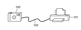
図1は、デジタルカメラとプリンタとの有線接続例を示す図である。図1に示すように、デジタルカメラ100とプリンタ101とを直接USBなどの有線のケーブル102で接続し、画像データを印刷する場合、ユーザは使用前後で有線ケーブル102を抜き差しする必要がある。そこで、ユーザの煩雑な操作さを軽減させる意味でケーブルリプレイスとしての無線化が検討されている。
FIG. 1 is a diagram illustrating an example of a wired connection between a digital camera and a printer. As shown in FIG. 1, when a
単に、無線対応のデジタルカメラと無線対応のプリンタとで無線化が可能であることは当然のことではあるが、同時に既存の有線対応のプリンタに無線通信機器を接続することで既存の有線プリンタを利用するユーザも無線化のサービスを享受したい、という要望がある。 Of course, it is natural that a wireless digital camera and a wireless printer can be wireless, but at the same time, an existing wired printer can be installed by connecting a wireless communication device to the existing wired printer. There is a demand for users who want to enjoy wireless services.
しかしながら、既存の有線プリンタでの動作は、例えば特許文献1にあるように、有線で接続されると自動的にデジタルカメラと接続された動作シーケンスが動作してしまう。 However, as for the operation in the existing wired printer, for example, as disclosed in Patent Document 1, when connected by wire, an operation sequence connected to the digital camera automatically operates.
そのため、無線通信機器とプリンタが接続された際に、まだ無線対応のデジタルカメラと無線通信機器の間の無線接続が完了していない場合には、プリンタはデジタルカメラとの接続に失敗してしまい、所望の印刷が行えない結果になるという課題がある。 Therefore, when the wireless communication device and the printer are connected, if the wireless connection between the wireless compatible digital camera and the wireless communication device is not yet completed, the printer fails to connect to the digital camera. There is a problem that the desired printing cannot be performed.
また、USBの接続に関しては、無線通信機器とプリンタとの間はUSBで接続され、その場合、無線通信機器のUSBデバイスがプリンタのUSBホストと接続される。ところが、無線通信機器のUSBデバイスは、パーソナルコンピュータ(以下、PC)と接続され、PCから無線通信に必要なネットワークやセキュリティーの情報を無線通信機器に設定することがある。 As for USB connection, the wireless communication device and the printer are connected by USB. In this case, the USB device of the wireless communication device is connected to the USB host of the printer. However, a USB device of a wireless communication device is connected to a personal computer (hereinafter referred to as a PC), and network and security information necessary for wireless communication may be set in the wireless communication device from the PC.
即ち、無線通信機器は自身のUSBデバイスに接続される通信相手がプリンタかPCかでその動作が変わってしまうため、無線通信機器にはそれらの複数の動作モードに適した制御を行わなければならないという課題がある。 That is, since the operation of a wireless communication device changes depending on whether the communication partner connected to its USB device is a printer or a PC, the wireless communication device must perform control suitable for the plurality of operation modes. There is a problem.
本発明は上記課題を解決するためになされたもので、通信インタフェースに接続される装置に応じて、その装置との通信を制御することを目的とする。 SUMMARY An advantage of some aspects of the invention is that it controls communication with a device connected to a communication interface according to the device connected to the communication interface.
本発明は、複数の通信インタフェースを有する通信装置であって、第1の通信インタフェースを介して第1の通信装置から送信されるデータの種別に応じて前記第1の通信装置との通信を抑制するか否かを決定する決定手段と、前記決定手段による決定に応じて、前記第1の通信装置との通信を抑制する抑制手段と、第2の通信インタフェースによる第2の通信装置との通信を確立する確立手段と、前記第2の通信装置との通信が確立した後に、前記第1の通信装置との通信抑制を解除する解除手段と、前記第1の通信インタフェース及び前記第2の通信インタフェースを介して前記第1の通信装置と前記第2の通信装置との間のデータ通信を中継する中継手段とを有することを特徴とする。 The present invention is a communication device having a plurality of communication interfaces, and suppresses communication with the first communication device according to the type of data transmitted from the first communication device via the first communication interface. Communication between the determination means for determining whether or not to perform, suppression means for suppressing communication with the first communication device according to the determination by the determination means, and communication with the second communication device by the second communication interface An establishment means for establishing communication, a release means for releasing communication suppression with the first communication apparatus after communication with the second communication apparatus is established, the first communication interface, and the second communication. It has relay means for relaying data communication between the first communication device and the second communication device via an interface.
本発明によれば、通信インタフェースに接続される通信装置に応じて、その通信装置との通信を制御することにより、ユーザが複雑な操作を行うことなく、通信インタフェースの異なる通信装置と接続して通信を行うことができる。 According to the present invention, according to the communication device connected to the communication interface, the communication with the communication device is controlled, so that the user can connect to the communication device with a different communication interface without performing a complicated operation. Communication can be performed.
以下、図面を参照しながら発明を実施するための最良の形態について詳細に説明する。 The best mode for carrying out the invention will be described below in detail with reference to the drawings.
[第1の実施形態]
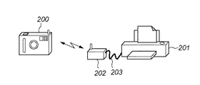
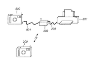
図2は、第1の実施形態におけるデジタルカメラとプリンタとの接続形態例を示す図である。図2において、200は無線対応のデジタルカメラであり、IEEE802.11b/11g/11aなどに代表されるWLAN(Wireless Local Area Network)やBluetooth(登録商標)などの無線通信機能を有する。201は既存の有線(USBケーブル)対応のプリンタである。202は第1の実施形態における無線通信機器であり、USBや無線LANなどの複数の通信インタフェースを有する無線アダプタである。無線アダプタ202は、USBケーブル203でプリンタ201と接続されると共に、無線LANによりデジタルカメラ200と通信を行い、デジタルカメラ200から送信された画像データをUSBケーブル203を介してプリンタ201へ送信する。
[First Embodiment]
FIG. 2 is a diagram illustrating an example of a connection form between the digital camera and the printer in the first embodiment. In FIG. 2,
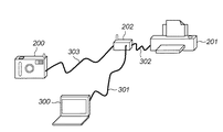
尚、この無線アダプタ202は、図3に示すように、パーソナルコンピュータ(PC)300とUSBケーブル301で接続された場合にはPC300から無線アダプタ202への無線情報の設定が行われ、プリンタ201とUSBケーブル302で接続された場合には印刷用の無線通信中継器として利用される。また、デジタルカメラ200とUSBケーブル303で接続された場合にはデジタルカメラ200と無線情報設定のペアリングを行うために利用される。
As shown in FIG. 3, when the
次に、図4を用いて、上述した複数の動作モードと複数の通信インタフェースを有する無線アダプタ202の構成について説明する。
Next, the configuration of the
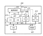
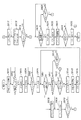
図4は、第1の実施形態における無線アダプタ202の構成の一例を示すブロック図である。図4において、401はCPU、402はRAM、403はROM、404は電源制御部、405はUSBデバイスコントローラ(USB-Device-Ctr)、406はUSBホストコントローラ(USB-Host-Ctr)、407は無線部、408は無線アダプタ202の内部バスである。
FIG. 4 is a block diagram illustrating an example of the configuration of the
409はUSBデバイス(USB-Device)コネクタ、410はUSBホスト(USB-Host)コネクタ、411はUSBデバイスが接続されたか否かを検出する信号(Vbus)である。412は電源制御部404をCPU401が制御するための制御信号、413は電源制御部404により制御されるUSBホストコントローラ406用電源、414は電源制御部404により制御される無線部407用電源、415は電源制御部404により制御されるUSBデバイスコントローラ405用電源である。
409 is a USB device connector, 410 is a USB host connector, and 411 is a signal (Vbus) for detecting whether or not a USB device is connected. 412 is a control signal for the
そして、416は無線アダプタ202の接続状態などを表示するLCDやLEDなどで構成された表示器である。
図5は、USBデバイス側でデータ信号線を用いたUSBバスリセットの構成の一例を示す図である。図5において、501、502はUSBデータ信号線、503、504はプルアップ抵抗(PullUP抵抗)、505、506はプルアップ抵抗とデータ信号線の接続を制御するスイッチである。そして、USBデバイスコネクタ409に接続されたUSBデバイスとデータの送受信を行う際に、プルアップ抵抗503、504を通信速度に応じてスイッチ505、506によりオンにすることでデータ送受信を開始する。
FIG. 5 is a diagram illustrating an example of a configuration of USB bus reset using a data signal line on the USB device side. In FIG. 5, 501 and 502 are USB data signal lines, 503 and 504 are pull-up resistors (PullUP resistors), and 505 and 506 are switches that control connection between the pull-up resistors and the data signal lines. When data is transmitted / received to / from the USB device connected to the
次に、図6を用いて、無線アダプタ202のUSBデバイスコネクタ409に他の機器としてPC300又はプリンタ201がUSBケーブルで接続された場合にCPU401が実行する接続制御について説明する。
Next, connection control executed by the
尚、CPU401はプログラマブルタイマを有し、後述するタイマ1、タイマ2の計時を行うものとする。本来USB通信では、クラス応答として自分が対応しているクラスの応答を返し、接続された機器からのデータ受信を待つが、もし「偽」のクラス応答を返した場合には、接続された機器(ここでは、プリンタ)は所望の機器(ここでは、デジタルカメラ)との接続でないことを識別し、データを送信しなくなることがある。
Note that the
タイマ1は、このような場合に、接続された機器からの受信データを待つタイマであり、タイマ1の満了を待って次の処理に進むことにより、無線LANの接続を先に確立した上で、再度プリンタの通信を有効にし、プリンタが無線アダプタを介したデジタルカメラとの無線通信を行うことができる。 In such a case, the timer 1 is a timer that waits for received data from the connected device. After the timer 1 expires, the process proceeds to the next process, and the wireless LAN connection is established first. The printer communication can be enabled again, and the printer can perform wireless communication with the digital camera via the wireless adapter.
また、タイマ2はデジタルカメラと無線アダプタとの接続確認を行う際のタイマであり、起動しているタイマ2が満了した場合、即ちデジタルカメラが存在しない場合、或いは接続が行われなかった場合には、無線アダプタ202はCPUスリープモードへ移行することで、低消費電力で動作を行うことができる。
The timer 2 is a timer for confirming the connection between the digital camera and the wireless adapter. When the activated timer 2 expires, that is, when the digital camera does not exist or when the connection is not performed. The
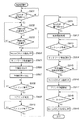
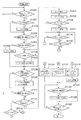
図6は、第1の実施形態における無線アダプタの接続制御処理を示すフローチャートである。まず、無線アダプタ202の電源が投入されると、ステップS601へ進み、無線アダプタ202の初期化を行う。次に、ステップS602において、USBデバイスコネクタ409に他の機器が接続されたか否かを信号(Vbus)411によってチェックする。ここで、信号411がハイになると、他の機器が接続されたと認識し、ステップS603へ進み、データ転送可能を示すデータの転送スピードに応じてスイッチ505、506によりプルアップ抵抗503、504をオンにし、接続機器との間でデータ転送許可状態にする。そして、ステップS604において、接続相手識別までの時間を計時するタイマ1を起動する。
FIG. 6 is a flowchart showing connection control processing of the wireless adapter in the first embodiment. First, when the power of the
次に、ステップS605において、USBデバイスコネクタ409に接続された機器からのUSBクラスの問い合わせ受信を待ち、受信するとステップS606へ進み、クラスの応答を返答する。これ以降は、接続された機器から送信されるデータを確認し、機器の種別(第1の実施形態ではプリンタなのかPCなのかを調べる)と接続方法とを確認する処理である。
Next, in step S605, it waits for reception of a USB class inquiry from the device connected to the
まず、ステップS607において、例えば受信データが無線情報設定を表すペアリング信号であれば、図3に示すPC300とUSBケーブル301による接続であると識別し、ステップS608へ進み、ペアリングモードへ移行する。そして、ステップS609において、無線アダプタ202はPC300との間でペアリングを実行する。ペアリングでは、無線情報がPC300から無線アダプタ202へ転送され、これ以降、無線アダプタ202は転送された無線情報に従って無線ネットワークを形成する。
First, in step S607, for example, if the received data is a pairing signal representing wireless information setting, it is identified that the connection is made by the PC 300 and the
次に、ステップS610において、ペアリングが完了したか否かを判定し、完了するとステップS617へ進み、データの送受信を不許可とするためにスイッチ505、506によりプルアップ抵抗503、504をオフにする。そして、ステップS618において、所定の時間(n秒)、CPUスリープモードに入り、ステップS619において、PC300と無線アダプタ202との接続であるUSBケーブル301が抜かれるのを確認するために信号411のチェックを行う。その後、PC300からのUSBケーブル301が抜かれると、この処理を終了する。
Next, in step S610, it is determined whether or not pairing is completed, and if completed, the process proceeds to step S617, and the pull-up
また、上述のステップS607において、USBデバイスコネクタ409に接続された機器からのデータがペアリング信号でなければステップS611へ進む。このステップS611では、その他の信号を受信したのか否かを判定し、信号を何も受信していなければステップS612へ進み、タイマ1が満了するまでステップS607に戻り、信号の受信待ちを続ける。その後、タイマ1が満了するまで、ペアリング信号もその他の信号も受信しなければ、詳細は後述するステップS614へ進む。
In step S607 described above, if the data from the device connected to the
また、ステップS611において、その他の信号を受信した場合はステップS613へ進み、所定のプリンタからの信号、即ち、接続された機器がプリンタ201であるか否かを確認する。ここで、プリンタ201からの信号でない場合には、ステップS617へ進み、上述した処理を実行する。
If another signal is received in step S611, the process advances to step S613 to check whether a signal from a predetermined printer, that is, whether the connected device is the
一方、プリンタ201からの信号を受信した場合には、ステップS614へ進み、プリンタ201との間でデータの送受信を不許可とするためにスイッチ505、506によりプルアップ抵抗503、504をオフにする。そして、ステップS615において、無線部407による無線LANの接続を開始し、ステップS616において、無線を介したデジタルカメラ200との接続を確認するためのタイマ2を起動する。
On the other hand, if a signal is received from the
次に、ステップS620において、デジタルカメラ200との接続確認を行い、接続が確認できるとステップS621へ進み、接続確認タイマ2を停止する。次に、ステップS622において、プリンタ201との間でデータ送受信を許可するためにスイッチ505、506によりプルアップ抵抗503、504をオンにする。そして、ステップS623において、プリンタ201がデジタルカメラ200と接続された場合の動作を自動的に開始するので、デジタルカメラ200とプリンタ201との間で無線アダプタ202を介した通信が開始される。
Next, in step S620, the connection with the
次に、ステップS624において、印刷データを受信し、デジタルカメラ200と無線アダプタ202の間で通信を行っている通信ポートがクローズされたか否かを確認する。ここで、通信ポートがクローズされるとステップS625へ進み、データ通信を不許可にするためにスイッチ505、506によりプルアップ抵抗503、504をオフにして、この処理を終了する。
Next, in step S624, the print data is received, and it is confirmed whether or not the communication port performing communication between the
また、上述のステップS620において、デジタルカメラ200との接続が確認できなければステップS626へ進み、タイマ2が満了したか判定し、満了するまで接続確認を続行する。その後、接続を確認できないまま、タイマ2が満了すると、ステップS617へ進み、上述した処理を実行する。
If the connection with the
次に、無線対応のデジタルカメラ200が無線アダプタ202を介して既存の有線対応のプリンタ201に無線通信により画像データファイルを転送し、プリンタ201で印刷を行う場合のシーケンスについて説明する。
Next, a sequence when the wireless
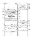
図7は、第1の実施形態における無線アダプタ202を介してデジタルカメラ200とプリンタ201が無線により印刷を行う場合のシーケンスを示す図である。まず、図2に示すように、無線アダプタ202がプリンタ201とUSBケーブル203で接続されると、プリンタ201から無線アダプタ202へクラス問い合わせ(701)が送られる。そして、無線アダプタ202がプリンタ201に対してクラス応答(702)を返答すると、プリンタ201からデジタルカメラ200とのセッション開始を表すPTPオープンセッション(703)が送られる。ここで、無線アダプタ402は、まだデジタルカメラ200との間で無線接続が確立していないので、一旦、プリンタ201との通信を不許可にするために、上述したプルアップ抵抗503、504をオフにする(704)。
FIG. 7 is a diagram illustrating a sequence when the
次に、無線アダプタ202は無線LAN接続を開始し、アドホックネットワークを形成し(705)、デジタルカメラ200から形成確認を受信すると(706)、ネットワークに参加したことをマルチキャストで同一のネットワークに存在する機器に送信する(707)。ここで、デジタルカメラ200が、プリントサービスを有する機器の検索を行うために、マルチキャストでサービス能力問い合わせを行う(708)。これにより、無線通信アダプタ202は同一のネットワークに存在し、プリンタ201と接続して、デジタルカメラ200にプリントサービスを提供できるのでサービス能力の応答をデジタルカメラ200に対して送信する(709)。
Next, the
次に、デジタルカメラ200が無線アダプタ202に機器の詳細な情報を獲得するための機器情報問い合わせを行う(710)。これにより、無線アダプタ202は機器情報応答をデジタルカメラ200に対して返答する(711)。その後、デジタルカメラ200がプリンタ201とデータ通信を行うためのTCPセッションを確立し(712)、その確立を確認した無線アダプタ202はプリンタ201とのデータ通信を許可するために、上述したプルアップ抵抗をオンにする(713)。
Next, the
これにより、無線アダプタ202はプリンタ201からのクラス問い合わせ(714)を受信し、クラス応答(715)を送信する。今度はデジタルカメラ200と無線アダプタ202との間で無線リンクが確立し、無線通信が行える状態にあるので、プリンタ201とデジタルカメラ200との間で画像データファイルを転送するための上位プロトコルとなるPTPセッションを確立する(716)。その後、PTPセッションで画像データファイルが無線アダプタ202を介してデジタルカメラ200からプリンタ201へ転送され(717)、デジタルカメラ200が画像データファイルを送り終わると、データ通信用のTCPセッションを終了する(718)。
As a result, the
次に、無線アダプタ202はデジタルカメラ200との無線通信が終了したことを識別し、プリンタ201に対して上述のプルアップ抵抗をオフにし、データの送受信が不許可になったことを通知する(719)。そして、継続して同一ネットワークに存在する機器に対してマルチキャストでネットワークにまだ参加していることを表す信号を送信する(720)。
Next, the
第1の実施形態によれば、複数の動作モードと複数の通信インタフェースを有する無線アダプタ202において、無線対応のデジタルカメラ200が既存の有線対応のプリンタ201と通信する際に、デジタルカメラ200との無線通信が可能になってからプリンタ201を動作させるように制御することにより、ユーザに対して複雑な操作を行わせずに無線通信が可能となる。
According to the first embodiment, when the wireless compatible
また、無線アダプタ202の電源が投入されると直に無線を動作させずに、動作モードに応じて無線の動作を制御することで消費電力の低減も図れる。
In addition, when the power of the
[第2の実施形態]
次に、図面を参照しながら本発明に係る第2の実施形態について詳細に説明する。第1の実施形態では、無線アダプタ202のUSBデバイスコネクタ409にPC300又はプリンタ201が接続された場合を例に説明したが、第2の実施形態では、USBホストコネクタ410にデジタルカメラがUSBケーブルで接続された場合を例に無線アダプタ202の抑制制御について説明する。
[Second Embodiment]
Next, a second embodiment according to the present invention will be described in detail with reference to the drawings. In the first embodiment, the case where the
尚、第2の実施形態における無線アダプタの構成は、図4を用いて説明した第1の実施形態の構成と同様であり、その説明は省略する。 Note that the configuration of the wireless adapter in the second embodiment is the same as the configuration of the first embodiment described with reference to FIG.
図8は、第2の実施形態におけるにおけるデジタルカメラとプリンタとの接続形態例を示す図である。図8に示すように、第2の実施形態では、図2に示す第1の実施形態での接続形態に加えて、デジタルカメラ800がUSBケーブル801で無線アダプタ202のUSBホストコネクタ410に接続されるものである。尚、デジタルカメラ800は、無線情報設定のペアリングを行うために無線アダプタ202に接続されるものである。
FIG. 8 is a diagram illustrating an example of a connection form between a digital camera and a printer in the second embodiment. As shown in FIG. 8, in the second embodiment, in addition to the connection form in the first embodiment shown in FIG. 2, the
次に、図9を用いて、無線アダプタ202がネットワークに参加しているときにUSBホストコネクタ410にデジタルカメラ800がUSBケーブル801で接続された場合にCPU401が実行する抑制制御処理について説明する。
Next, a suppression control process executed by the
図9は、第2の実施形態における無線アダプタの抑制制御処理を示すフローチャートである。まず、無線LANが起動している状態で開始し、ステップS901でUSBホストコネクタ410のデータ信号線がハイ(High)になったことを検知すると、USBホストコネクタ410に機器(この例では、デジタルカメラ800)が接続されたと判定する。そして、ステップS902では、無線の状態が自機器の存在をマルチキャストで通知中か否かを判定する。ここで、通知中であればステップS904へ進み、また通知中でなければステップS903へ進む。
FIG. 9 is a flowchart illustrating the suppression control process of the wireless adapter according to the second embodiment. First, when the wireless LAN is activated, when it is detected in step S901 that the data signal line of the
ステップS903では、無線アダプタ202がデジタルカメラ200と無線通信中か否かを判定する。ここで、通信中の場合にはステップS902に戻り、通信が終了するまで待つ。そして、通知中か、通信が終了すると、ステップS904において、プリンタ201と接続されているUSBデバイスコネクタ409のプルアップ抵抗をオフにしてデータ通信を不可能にする。次に、ステップS905において、無線ネットワークからの脱退通知を同一ネットワークに存在する機器に対してマルチキャストで通知する。
In step S903, it is determined whether or not the
次に、ステップS906において、無線を停止する処理を行い、続くステップS907において、無線状態をアイドル(IDLE)に設定する。そして、ステップS908において、USBホストコネクタ410にUSBケーブルで接続されたデジタルカメラ800から無線情報設定ペアリング要求があるとステップS909へ進み、ペアリングを開始する。その後、ペアリング終了を確認すると、ステップS910からステップS911へ進み、デジタルカメラ800からのUSBケーブル801が抜かれてデータ信号線がローになると、接続終了と判定し、ステップS912へ進み、無線通信の開始処理を行う。
Next, in step S906, a process of stopping radio is performed, and in subsequent step S907, the radio state is set to idle (IDLE). In step S908, if there is a wireless information setting pairing request from the
次に、ステップS913において、ネットワークが形成されると、ステップS914へ進み、自機器のネットワーク参加通知をマルチキャストで送信する。そして、ステップS915において、デジタルカメラ200との接続が確認されると、ステップS916において、USBデバイスのプルアップ抵抗をオンにする。そして、ステップS917において、プリンタ201との通信を開始し、ステップS918において、通信完了を検知すると、ステップS919において、上述したプルアップ抵抗をオフにし、プリンタ201との通信を不可能にした状態で終了する。
Next, when a network is formed in step S913, the process proceeds to step S914, and a network participation notification of the own device is transmitted by multicast. When the connection with the
第2の実施形態によれば、無線通信状態に応じてプリンタ201と無線アダプタ202の通信抑制を制御することで、無線アダプタ202がデジタルカメラ200と通信中に、ペアリングの要求を他のデジタルカメラ800から受けた場合でも、無線通信中の動作を妨害されることなく、制御を行うことができる。
According to the second embodiment, by controlling communication suppression between the
[第3の実施形態]
次に、図面を参照しながら本発明に係る第3の実施形態について詳細に説明する。尚、第3の実施形態は、第1の実施形態とほぼ同等であるが、無線アダプタ202がプリンタ201と接続された場合に、無線LANが接続されるまでプリンタ201からの要求信号を内部で保留する場合の抑制制御を行うものである。
[Third Embodiment]
Next, a third embodiment according to the present invention will be described in detail with reference to the drawings. The third embodiment is almost the same as the first embodiment. However, when the
尚、第3の実施形態における無線アダプタの構成は、図4を用いて説明した第1の実施形態の構成と同様であり、その説明は省略する。 The configuration of the wireless adapter in the third embodiment is the same as that of the first embodiment described with reference to FIG.
次に、図10を用いて、図2に示した接続形態で無線アダプタ202のUSBデバイスコネクタ409に他の機器としてPC300又はプリンタ201がUSBケーブルで接続された場合にCPU401が実行する接続制御について説明する。
Next, with reference to FIG. 10, connection control executed by the
図10は、第3の実施形態における無線アダプタの接続制御処理を示すフローチャートである。まず、無線アダプタ202の電源が投入されると、ステップS1001へ進み、無線アダプタ202の初期化を行う。次に、ステップS1002において、USBデバイスコネクタ409に他の機器が接続されたか否かを信号(Vbus)411によってチェックする。ここで、信号411がハイになると、他の機器が接続されたと認識し、ステップS1003へ進み、データ転送可能を示すデータの転送スピードに応じてスイッチ505、506によりプルアップ抵抗503、504をオンにする。
FIG. 10 is a flowchart illustrating connection control processing of the wireless adapter according to the third embodiment. First, when the power of the
次に、ステップS1005において、USBデバイスコネクタ409に接続された機器からのUSBクラスの問い合わせ受信を待ち、受信するとステップS1006へ進み、クラスの応答を返答する。これ以降は、接続された機器から送信されるデータを確認し、機器の種別(第3の実施形態ではプリンタなのかPCなのかを調べる)と接続方法とを確認する処理である。
Next, in step S1005, it waits for reception of a USB class inquiry from the device connected to the
まず、ステップS1007において、例えば受信データが無線情報設定を表すペアリング信号であれば、図3に示すPC300とUSBケーブル301による接続であると識別し、ステップS1008へ進み、ペアリングモードへ移行する。そして、ステップS1009において、無線アダプタ202はPC300との間でペアリングを実行する。ペアリングでは、無線情報がPC300から無線アダプタ202へ転送され、これ以降、無線アダプタ202は転送された無線情報に従って無線ネットワークを形成する。
First, in step S1007, if the received data is a pairing signal indicating wireless information setting, for example, it is identified that the connection is made by the
次に、ステップS1010において、ペアリングが完了したか否かを判定し、完了するとステップS1015へ進み、データの送受信を不許可とするためにスイッチ505、506によりプルアップ抵抗503、504をオフにする。そして、ステップS1016において、所定の時間(n秒)、CPUスリープモードに入り、ステップS1017において、PC300と無線アダプタ202との接続であるUSBケーブル301が抜かれるのを確認するために信号411のチェックを行う。その後、PC300からのUSBケーブル301が抜かれると、この処理を終了する。
Next, in step S1010, it is determined whether or not pairing is completed, and if completed, the process proceeds to step S1015, and the pull-up
また、上述のステップS1007において、USBデバイスコネクタ409に接続された機器からのデータがペアリング信号でなければステップS1011へ進み、その他の信号を受信するのを待つ。その後、その他の信号を受信するとステップS1012へ進み、プリンタ201から要求された信号を内部で保留する。そして、ステップS1013において、無線LANの接続を開始し、ステップS1014において、無線を介したデジタルカメラ200との接続を確認するためのタイマ2を起動する。
If the data from the device connected to the
次に、ステップS1018において、デジタルカメラ200との接続確認を行い、接続が確認できるとステップS1019へ進み、接続確認タイマ2を停止する。次に、ステップS1021において、保留していた要求信号の保留解除を行い、プリンタ201へ送信する。そして、ステップS1022において、デジタルカメラ200とプリンタ201との間で無線アダプタ202を介した通信が開始される。
Next, in step S1018, the connection with the
次に、ステップS1023において、印刷データを受信し、デジタルカメラ200と無線アダプタ202の間で通信を行っている通信ポートがクローズされたか否かを確認する。ここで、通信ポートがクローズされるとステップS1024へ進み、データ通信を不許可にするためにスイッチ505、506によりプルアップ抵抗503、504をオフにして、この処理を終了する。
Next, in step S1023, the print data is received, and it is confirmed whether or not the communication port performing communication between the
また、上述のステップS1018において、デジタルカメラ200との接続が確認できなければステップS1020へ進み、タイマ2が満了したか判定し、満了するまで接続確認を続行する。その後、接続を確認できないまま、タイマ2が満了すると、ステップS1015へ進み、上述した処理を実行する。
If the connection with the
第3の実施形態によれば、USBを途中でリセットしそれをきっかけにプリンタ側を再度通信初期化処理から行わせるような制御を行う必要がない。そのため、特にUSBだけに依存せず、例えばIEEE1394などで無線アダプタと接続する構成でも同様の効果を得ることができる。 According to the third embodiment, there is no need to perform control that resets the USB halfway and causes the printer side to start again from the communication initialization process. For this reason, the same effect can be obtained even when the wireless adapter is connected to the wireless adapter by, for example, IEEE1394, without depending on USB alone.
[第4の実施形態]
次に、図面を参照しながら本発明に係る第4の実施形態について詳細に説明する。第4の実施形態では、第2の実施形態と同様にUSBホストコネクタ410にデジタルカメラがUSBケーブルで接続された場合を例に無線アダプタの抑制制御について説明する。
[Fourth Embodiment]
Next, a fourth embodiment according to the present invention will be described in detail with reference to the drawings. In the fourth embodiment, the suppression control of the wireless adapter will be described by taking as an example a case where a digital camera is connected to the
尚、第4の実施形態における無線アダプタの構成は、図4を用いて説明した第2の実施形態の構成と同様であり、その説明は省略する。 Note that the configuration of the wireless adapter in the fourth embodiment is the same as the configuration of the second embodiment described with reference to FIG.
また、第4の実施形態でもデジタルカメラとプリンタとの接続形態として、第2の実施形態で用いた図8に示す接続形態を用いるものとする。 In the fourth embodiment, the connection form shown in FIG. 8 used in the second embodiment is used as the connection form between the digital camera and the printer.
次に、図11を用いて、無線アダプタ202がネットワークに参加しているときにUSBホストコネクタ410にデジタルカメラ800がUSBケーブル801で接続された場合にCPU401が実行する抑制制御処理について説明する。
Next, a suppression control process executed by the
図11は、第4の実施形態における無線アダプタの抑制制御処理を示すフローチャートである。まず、無線LANが起動している状態で開始し、ステップS1101で、USBホストコネクタ410のデータ信号線がハイ(High)になったことを検知すると、USBホストコネクタ410に機器(この例では、デジタルカメラ800)が接続されたと判定する。そして、ステップS1102では、ペアリング要求受信待ちタイマ1の開始状態を確認し、未開始であれば、ステップS1103へ進み、タイマ1を開始する。
FIG. 11 is a flowchart illustrating the suppression control process of the wireless adapter according to the fourth embodiment. First, the wireless LAN is activated, and when it is detected in step S1101 that the data signal line of the
次に、ステップS1104では、無線の状態が自機器の存在をマルチキャストで通知中か否かを判定する。ここで、通知中であればステップS1106へ進み、また通知中でなければステップS1105へ進む。ステップS1105では、無線状態がデジタルカメラ200と通信中か否かを判定する。ここで、通信中でない場合にはステップS1106へ進み、デバイス状態がアイドル(IDLE)か否かを判定する。その結果、アイドルであればステップS1107へ進み、デバイス状態をビジー(BUSY)に設定する。
Next, in step S1104, it is determined whether or not the wireless state is notifying the presence of the own device by multicast. If notification is in progress, the process proceeds to step S1106. If not, the process proceeds to step S1105. In step S1105, it is determined whether the wireless state is communicating with the
また、上述のステップS1105において、無線状態がデジタルカメラ200と通信中であればステップS1108へ進み、タイマ1を停止し、ステップS1109へ進む。
In step S1105 described above, if the wireless state is communicating with the
その後、ステップS1109において、デジタルカメラ200からデバイス情報の問い合わせ要求を受信するとステップS1110へ進み、デバイスの状態をビジーに設定し、デバイス情報問合せ応答を送信する。そして、ステップS1111において、無線状態が通信中か否かを判定し、通信中の場合はステップS1101に戻る。
After that, when a device information inquiry request is received from the
次に、ステップS1112において、デジタルカメラ800からのUSBによるペアリング要求を受信したか否かを判定し、受信した場合はステップS1114へ進み、タイマ1を停止する。そして、ステップS1115において、ペアリングを開始し、ステップS1116において、タイマ2が開始されているか否かを判定する。ここで、開始されていれば、そのままステップS1118へ進み、開始されていなければステップS1117へ進み、タイマ2を開始してステップS1118へ進む。
Next, in step S1112, it is determined whether or not a USB pairing request from the
このステップS1118では、ペアリングの終了を待ち、終了していなければステップS1119へ進み、ペアリング終了待ちタイマ2が満了したか否かを判定する。ここで、タイマ2が満了していない場合にはステップS1118に戻り、ペアリング終了を待つ。またタイマ2が満了した場合にはステップS1121へ進み、無線アダプタ202の表示器416に警告メッセージとして、例えば「ペアリングは終了できませんでした。ケーブルを抜いて下さい」を表示する。これは、ペアリング途中で電池残量が処理を行うだけの十分な量を下回り、処理が不完全だった場合に表示される。
In step S1118, the process waits for the end of pairing. If not completed, the process advances to step S1119 to determine whether the pairing end wait timer 2 has expired. If the timer 2 has not expired, the process returns to step S1118 and waits for the end of pairing. If timer 2 has expired, the process proceeds to step S1121, and a warning message is displayed on the
また、上述したステップS1118において、ペアリングが終了した場合はステップS1122へ進み、無線アダプタ202の表示器416にメッセージとして、例えば「ペアリングは終了しました。ケーブルを抜いて下さい」を表示する。これは、ペアリングが正常に終了した場合の基本である。
If the pairing is completed in step S1118 described above, the process proceeds to step S1122, and a message such as “Pairing is complete. Please disconnect the cable” is displayed on the
一方、上述したステップS1112において、ペアリング要求を受信していない場合はステップS1113へ進み、ペアリング要求受信待ちタイマ1が満了したか否かを判定する。ここで、タイマ1が満了していない場合はステップS1101に戻る。また満了した場合はステップS1120へ進み、無線アダプタ202の表示器416に警告メッセージとして、例えば「デバイス状態を確認しケーブルを抜いて下さい」を表示する。これは、例えばデジタルカメラ800とは全く無関係の機器が無線アダプタ202のUSBホストコネクタ410に接続された場合などに発生することが考えられる。
On the other hand, if the pairing request has not been received in step S1112 described above, the process proceeds to step S1113, and it is determined whether or not the pairing request reception waiting timer 1 has expired. If the timer 1 has not expired, the process returns to step S1101. If it has expired, the process advances to step S1120 to display, for example, “Please check the device status and disconnect the cable” on the
このように、ステップS1120〜S1122の何れかの処理が終了すると、ステップS1124へ進み、無線状態が通知中か否かを判定する。ここで、通知中でなければそのままステップS1126へ進み、通知中であればステップS1125へ進み、デバイスの状態をビジー状態からアイドル状態に設定してステップS1126へ進む。このステップS1126では、USBケーブル801が抜かれたことを確認するために、USBホストコネクタ410のデータ信号線がローか否かを判定する。そして、データ信号線がローになると、この処理を終了する。
As described above, when any one of steps S1120 to S1122 is completed, the process proceeds to step S1124, and it is determined whether or not the wireless state is being notified. If the notification is not in progress, the process directly proceeds to step S1126. If the notification is in progress, the process proceeds to step S1125, the device state is set from the busy state to the idle state, and the process proceeds to step S1126. In step S1126, in order to confirm that the
尚、ペアリング終了時に表示する警告メッセージは、例えばパスワード入力などを促された場合にパスワード認証で失敗したときに表示するようにしても良い。 Note that the warning message displayed at the end of pairing may be displayed, for example, when password authentication fails when prompted to enter a password.
以上説明した実施形態では、無線アダプタとデジタルカメラがペアリングを行う際に、他の無線機器からペアリングが要求された場合に、無線を一旦停止せずに接続の制御のみを抑制する。これにより、無線接続を行いたいデジタルカメラは状態変化(BUSY⇒IDLE)をポーリングによって監視することで再接続にかかる無線ネットワーク構築までに必要な時間、例えば「ネットワークスキャン・ネットワーク参加・IPアドレス割当・機器検索」を省略することができ、次に印刷を行うまでの時間を大幅に短縮できる。 In the embodiment described above, when pairing is requested from another wireless device when the wireless adapter and the digital camera perform pairing, only the connection control is suppressed without temporarily stopping the wireless connection. As a result, the digital camera that wants to establish a wireless connection monitors the state change (BUSY⇒IDLE) by polling, and the time required to establish a wireless network for reconnection, such as "Network Scan / Network Participation / IP Address Assignment / The “device search” can be omitted, and the time until the next printing can be greatly shortened.
また、以上説明した実施形態では、デバイス状態のBUSY設定をペアリング要求受信前に設定したが、これは無線接続を行いたいデジタルカメラがいち早く無線アダプタ及びプリンタのビジー(BUSY)状態を知ることができる効果がある反面、デジタルカメラ以外の機器がUSB接続された場合にもビジー(BUSY)と判断する可能性がある。 In the embodiment described above, the BUSY setting of the device state is set before the pairing request is received. This means that the digital camera that wants to establish a wireless connection can quickly know the busy state of the wireless adapter and the printer. Although there is an effect that can be achieved, there is a possibility that the device is determined to be busy (BUSY) even when a device other than the digital camera is connected via USB.
また、ペアリング要求受信後にデバイス状態をBUSYに設定した場合には、確実にBUSYを通知できる反面、判断が遅くなるため、USBホストコネクタのデータ信号線の状態からUSBペアリング要求の受信までに相当の時間が必要な場合には、デバイス情報問合せをアイドル(IDLE)で応答した後に、デジタルカメラから無線接続を許可する可能性がある。 In addition, if the device status is set to BUSY after receiving a pairing request, it is possible to reliably notify BUSY, but the judgment will be delayed, so from the status of the data signal line of the USB host connector to the reception of the USB pairing request. If a considerable amount of time is required, there is a possibility that a wireless connection is permitted from the digital camera after a device information inquiry is returned as an idle (IDLE).
しかしながら、実際にはこれら一連の時間はユーザ操作から見るとほとんど誤差に近い時間であるため、実施形態にあるようなタイマ1を設けることで、上述のデジタルカメラ以外の機器がUSB接続された場合のエラー検知も早急に行うことが可能である。 However, in actuality, these series of times are almost similar to errors when viewed from the user operation, and therefore, by providing the timer 1 as in the embodiment, when a device other than the above-described digital camera is connected by USB. It is possible to quickly detect errors.
また、第1乃至第4の実施形態では、無線通信方式として、IEEE 802.11xの無線LANのアドホックモードを例に説明したが、インフラストラクチャモード、Bluetooth(登録商標)、UWB,WiMAXなどの他の無線通信方式に本発明を適用することも可能である。 In the first to fourth embodiments, the IEEE 802.11x wireless LAN ad hoc mode has been described as an example of the wireless communication system. However, other infrastructure modes, Bluetooth (registered trademark), UWB, WiMAX, and the like have been described. The present invention can also be applied to a wireless communication system.
尚、本発明は複数の機器(例えば、ホストコンピュータ,インターフェース機器,リーダ,プリンタなど)から構成されるシステムに適用しても、1つの機器からなる装置(例えば、複写機,ファクシミリ装置など)に適用しても良い。 Even if the present invention is applied to a system composed of a plurality of devices (for example, a host computer, an interface device, a reader, a printer, etc.), it is applied to an apparatus (for example, a copier, a facsimile machine, etc.) composed of a single device. It may be applied.
また、本発明の目的は、前述した実施形態の機能を実現するソフトウェアのプログラムコードを記録した記録媒体を、システム或いは装置に供給し、そのシステム或いは装置のコンピュータ(CPU若しくはMPU)が記録媒体に格納されたプログラムコードを読出し実行することによっても、達成されることは言うまでもない。 Another object of the present invention is to supply a recording medium that records software program codes for realizing the functions of the above-described embodiments to a system or apparatus, and the computer (CPU or MPU) of the system or apparatus uses the recording medium as a recording medium. Needless to say, this can also be achieved by reading and executing the stored program code.
この場合、記録媒体から読出されたプログラムコード自体が前述した実施形態の機能を実現することになり、そのプログラムコードを記憶した記録媒体は本発明を構成することになる。 In this case, the program code itself read from the recording medium realizes the functions of the above-described embodiment, and the recording medium storing the program code constitutes the present invention.
このプログラムコードを供給するための記録媒体としては、例えばフロッピー(登録商標)ディスク,ハードディスク,光ディスク,光磁気ディスク,CD−ROM,CD−R,磁気テープ,不揮発性のメモリカード,ROMなどを用いることができる。 As a recording medium for supplying the program code, for example, a floppy (registered trademark) disk, a hard disk, an optical disk, a magneto-optical disk, a CD-ROM, a CD-R, a magnetic tape, a nonvolatile memory card, a ROM, or the like is used. be able to.
また、コンピュータが読出したプログラムコードを実行することにより、前述した実施形態の機能が実現されるだけでなく、そのプログラムコードの指示に基づき、コンピュータ上で稼働しているOS(オペレーティングシステム)などが実際の処理の一部又は全部を行い、その処理によって前述した実施形態の機能が実現される場合も含まれることは言うまでもない。 Further, by executing the program code read by the computer, not only the functions of the above-described embodiments are realized, but also an OS (operating system) operating on the computer based on the instruction of the program code. It goes without saying that a case where the function of the above-described embodiment is realized by performing part or all of the actual processing and the processing is included.
更に、記録媒体から読出されたプログラムコードが、コンピュータに挿入された機能拡張ボードやコンピュータに接続された機能拡張ユニットに備わるメモリに書込まれた後、そのプログラムコードの指示に基づき、その機能拡張ボードや機能拡張ユニットに備わるCPUなどが実際の処理の一部又は全部を行い、その処理によって前述した実施形態の機能が実現される場合も含まれることは言うまでもない。 Further, after the program code read from the recording medium is written in a memory provided in a function expansion board inserted into the computer or a function expansion unit connected to the computer, the function expansion is performed based on the instruction of the program code. It goes without saying that the CPU or the like provided in the board or the function expansion unit performs part or all of the actual processing and the functions of the above-described embodiments are realized by the processing.
100 デジタルカメラ
101 プリンタ
102 USBケーブル
200 無線対応のデジタルカメラ
201 有線対応のプリンタ
202 無線アダプタ
203 USBケーブル
300 パーソナルコンピュータ(PC)
301 USBケーブル
302 USBケーブル
303 USBケーブル
401 CPU
402 RAM
403 ROM
404 電源制御部
405 USBデバイスコントローラ(USB-Device-Ctr)
406 USBホストコントローラ(USB-Host-Ctr)
407 無線部
408 内部バス
409 USBデバイス(USB-Device)コネクタ
410 USBホスト(USB-Host)コネクタ
411 信号(Vbus)
412 制御信号
413 USBホストコントローラ306用電源
414 無線部307用電源
415 USBデバイスコントローラ305用電源
416 表示器
501 USBデータ信号線
502 USBデータ信号線
503 プルアップ抵抗(PullUP抵抗)
504 プルアップ抵抗(PullUP抵抗)
505 スイッチ
506 スイッチ
100 Digital Camera 101
301
402 RAM
403 ROM
404
406 USB host controller (USB-Host-Ctr)
412 Control signal 413 USB host controller 306
504 Pull-up resistor (PullUP resistor)
505
Claims (10)
第1の通信インタフェースを介して第1の通信装置から送信されるデータの種別に応じて前記第1の通信装置との通信を抑制するか否かを決定する決定手段と、
前記決定手段による決定に応じて、前記第1の通信装置との通信を抑制する抑制手段と、
第2の通信インタフェースによる第2の通信装置との通信を確立する確立手段と、
前記第2の通信装置との通信が確立した後に、前記第1の通信装置との通信抑制を解除する解除手段と、
前記第1の通信インタフェース及び前記第2の通信インタフェースを介して前記第1の通信装置と前記第2の通信装置との間のデータ通信を中継する中継手段と、
を有することを特徴とする通信装置。 A communication device having a plurality of communication interfaces,
Determining means for determining whether to suppress communication with the first communication device according to a type of data transmitted from the first communication device via the first communication interface;
In response to the determination by the determination unit, a suppression unit that suppresses communication with the first communication device;
Establishing means for establishing communication with the second communication device via the second communication interface;
Release means for canceling communication suppression with the first communication device after communication with the second communication device is established;
Relay means for relaying data communication between the first communication device and the second communication device via the first communication interface and the second communication interface;
A communication apparatus comprising:
第1の通信インタフェースを介して接続された第1の通信装置の種別に応じて前記第1の通信装置との通信を抑制するか否かを決定する決定手段と、
前記決定手段による決定に応じて、前記第1の通信装置との通信を抑制する抑制手段と、
第2の通信インタフェースによる第2の通信装置との通信を確立する確立手段と、
前記第2の通信装置との通信が確立した後に、前記第1の通信装置との通信抑制を解除する解除手段と、
前記第1の通信インタフェース及び前記第2の通信インタフェースを介して前記第1の通信装置と前記第2の通信装置との間のデータ通信を中継する中継手段と、
を有することを特徴とする通信装置。 A communication device having a plurality of communication interfaces,
Determining means for determining whether or not to suppress communication with the first communication device according to the type of the first communication device connected via the first communication interface ;
In response to the determination by the determination unit, a suppression unit that suppresses communication with the first communication device;
Establishing means for establishing communication with the second communication device via the second communication interface;
Release means for canceling communication suppression with the first communication device after communication with the second communication device is established;
Relay means for relaying data communication between the first communication device and the second communication device via the first communication interface and the second communication interface;
Communication device further comprising a.
第1の通信インタフェースを介して第1の通信装置から送信されるデータの種別に応じて前記第1の通信装置との通信を抑制するか否かを決定する決定工程と、A determining step for determining whether to suppress communication with the first communication device according to a type of data transmitted from the first communication device via the first communication interface;
前記決定工程における決定に応じて、前記第1の通信装置との通信を抑制する抑制工程と、In accordance with the determination in the determination step, a suppression step of suppressing communication with the first communication device,
第2の通信インタフェースによる第2の通信装置との通信を確立する確立工程と、An establishing step for establishing communication with the second communication device via the second communication interface;
前記第2の通信装置との通信が確立した後に、前記第1の通信装置との通信抑制を解除する解除工程と、After the communication with the second communication device is established, a release step for releasing the communication suppression with the first communication device;
前記第1の通信インタフェース及び前記第2の通信インタフェースを介して前記第1の通信装置と前記第2の通信装置との間のデータ通信を中継する中継工程と、A relay step of relaying data communication between the first communication device and the second communication device via the first communication interface and the second communication interface;
を有することを特徴とする通信装置の制御方法。A method for controlling a communication apparatus, comprising:
第1の通信インタフェースを介して接続された第1の通信装置の種別に応じて前記第1の通信装置との通信を抑制するか否かを決定する決定工程と、A determination step of determining whether to suppress communication with the first communication device according to a type of the first communication device connected via the first communication interface;
前記決定工程における決定に応じて、前記第1の通信装置との通信を抑制する抑制工程と、In accordance with the determination in the determination step, a suppression step of suppressing communication with the first communication device,
第2の通信インタフェースによる第2の通信装置との通信を確立する確立工程と、An establishing step for establishing communication with the second communication device via the second communication interface;
前記第2の通信装置との通信が確立した後に、前記第1の通信装置との通信抑制を解除する解除工程と、After the communication with the second communication device is established, a release step for releasing the communication suppression with the first communication device;
前記第1の通信インタフェース及び前記第2の通信インタフェースを介して前記第1の通信装置と前記第2の通信装置との間のデータ通信を中継する中継工程と、A relay step of relaying data communication between the first communication device and the second communication device via the first communication interface and the second communication interface;
を有することを特徴とする通信装置の制御方法。A method for controlling a communication apparatus, comprising:
Priority Applications (6)
| Application Number | Priority Date | Filing Date | Title |
|---|---|---|---|
| JP2005073953A JP4356997B2 (en) | 2005-03-15 | 2005-03-15 | Communication apparatus and communication method thereof |
| EP06251338A EP1703411B1 (en) | 2005-03-15 | 2006-03-14 | Communication apparatus and method |
| CNB2006100648310A CN100490489C (en) | 2005-03-15 | 2006-03-14 | Communication apparatus and method |
| DE602006016666T DE602006016666D1 (en) | 2005-03-15 | 2006-03-14 | Communication device and method |
| KR1020060023881A KR100815509B1 (en) | 2005-03-15 | 2006-03-15 | Communication apparatus and method |
| US11/376,796 US8037218B2 (en) | 2005-03-15 | 2006-03-15 | Communication apparatus and method |
Applications Claiming Priority (1)
| Application Number | Priority Date | Filing Date | Title |
|---|---|---|---|
| JP2005073953A JP4356997B2 (en) | 2005-03-15 | 2005-03-15 | Communication apparatus and communication method thereof |
Publications (3)
| Publication Number | Publication Date |
|---|---|
| JP2006261851A JP2006261851A (en) | 2006-09-28 |
| JP2006261851A5 JP2006261851A5 (en) | 2008-04-24 |
| JP4356997B2 true JP4356997B2 (en) | 2009-11-04 |
Family
ID=36498888
Family Applications (1)
| Application Number | Title | Priority Date | Filing Date |
|---|---|---|---|
| JP2005073953A Expired - Fee Related JP4356997B2 (en) | 2005-03-15 | 2005-03-15 | Communication apparatus and communication method thereof |
Country Status (6)
| Country | Link |
|---|---|
| US (1) | US8037218B2 (en) |
| EP (1) | EP1703411B1 (en) |
| JP (1) | JP4356997B2 (en) |
| KR (1) | KR100815509B1 (en) |
| CN (1) | CN100490489C (en) |
| DE (1) | DE602006016666D1 (en) |
Families Citing this family (29)
| Publication number | Priority date | Publication date | Assignee | Title |
|---|---|---|---|---|
| JP4125173B2 (en) | 2003-04-23 | 2008-07-30 | キヤノン株式会社 | Information processing apparatus connection control method, information processing apparatus, and computer program |
| JP4136771B2 (en) | 2003-04-23 | 2008-08-20 | キヤノン株式会社 | COMMUNICATION SYSTEM, COMMUNICATION DEVICE, ITS CONTROL METHOD, AND COMPUTER PROGRAM |
| JP4125172B2 (en) | 2003-04-23 | 2008-07-30 | キヤノン株式会社 | Wireless communication system, wireless communication apparatus, control method therefor, and computer program |
| JP4681960B2 (en) * | 2005-06-17 | 2011-05-11 | キヤノン株式会社 | COMMUNICATION DEVICE, COMMUNICATION DEVICE COMMUNICATION METHOD, AND COMPUTER PROGRAM |
| JP4886463B2 (en) | 2006-10-20 | 2012-02-29 | キヤノン株式会社 | Communication parameter setting method, communication apparatus, and management apparatus for managing communication parameters |
| US20080101272A1 (en) * | 2006-10-29 | 2008-05-01 | Sony Ericsson Mobile Communications Ab | Wireless Card and Card Holder for a Digital Camera |
| JP5008387B2 (en) * | 2006-12-06 | 2012-08-22 | キヤノン株式会社 | Wireless communication apparatus and control method thereof |
| US8909296B2 (en) * | 2007-05-14 | 2014-12-09 | Kopin Corporation | Mobile wireless display software platform for controlling other systems and devices |
| US9116340B2 (en) * | 2007-05-14 | 2015-08-25 | Kopin Corporation | Mobile wireless display for accessing data from a host and method for controlling |
| US9317110B2 (en) * | 2007-05-29 | 2016-04-19 | Cfph, Llc | Game with hand motion control |
| JP2008311950A (en) * | 2007-06-14 | 2008-12-25 | Canon Inc | Wireless communication system, and communication device and control method thereof |
| JP4977543B2 (en) * | 2007-07-20 | 2012-07-18 | 日本電気通信システム株式会社 | Control device, control system, control method, and control program |
| JP4618279B2 (en) * | 2007-08-16 | 2011-01-26 | ソニー株式会社 | Remote control system, receiving device and electronic device |
| US8355671B2 (en) * | 2008-01-04 | 2013-01-15 | Kopin Corporation | Method and apparatus for transporting video signal over Bluetooth wireless interface |
| CN102016975A (en) | 2008-03-28 | 2011-04-13 | 寇平公司 | Handheld wireless display device having high-resolution display suitable for use as a mobile internet device |
| JP2010152815A (en) * | 2008-12-26 | 2010-07-08 | Seiko Epson Corp | Information processor, information processing system, and control method of information processor |
| KR101543579B1 (en) * | 2009-02-18 | 2015-08-11 | 삼성전자주식회사 | Power feeding method for a device wired adapter device wired adapter and standalone usb device employing the power feeding method |
| JP2011008311A (en) * | 2009-06-23 | 2011-01-13 | Casio Computer Co Ltd | Input/output control device and electronic musical instrument |
| US20110047384A1 (en) * | 2009-08-21 | 2011-02-24 | Qualcomm Incorporated | Establishing an ad hoc network using face recognition |
| JP5487877B2 (en) * | 2009-10-20 | 2014-05-14 | セイコーエプソン株式会社 | USB device device |
| DE102010042116A1 (en) * | 2010-10-07 | 2012-04-12 | Endress + Hauser Process Solutions Ag | Method for enabling prompt diagnosis, field device connected to a wireless adapter |
| EP2719188B1 (en) * | 2011-06-09 | 2021-10-13 | InterDigital CE Patent Holdings | Method for exiting a low-consumption standby mode, and associated device |
| KR102105168B1 (en) * | 2013-05-15 | 2020-04-24 | 삼성전자주식회사 | Display apparatus and control method of the same |
| JP5713078B2 (en) * | 2013-10-08 | 2015-05-07 | 株式会社リコー | Information processing apparatus and information processing system |
| JP6512875B2 (en) * | 2015-03-10 | 2019-05-15 | キヤノン株式会社 | Communication device, control method of communication device, and program |
| JP6683013B2 (en) * | 2016-05-24 | 2020-04-15 | セイコーエプソン株式会社 | Printing apparatus and printing apparatus control method |
| US10445105B2 (en) * | 2018-01-29 | 2019-10-15 | Pixart Imaging Inc. | Scheme for automatically controlling dongle device and/or electronic device to enter waiting state of device pairing in which the dongle device and the electronic device exchange/share pairing information |
| CN108601010A (en) * | 2018-05-08 | 2018-09-28 | 湖州旭源电气科技有限公司 | The control system of camera wireless blue tooth transfer function can be achieved |
| JP2021145159A (en) * | 2020-03-10 | 2021-09-24 | セイコーエプソン株式会社 | Information processing system, communication connection control method of information processing device, communication connection control method of terminal device, and program |
Family Cites Families (90)
| Publication number | Priority date | Publication date | Assignee | Title |
|---|---|---|---|---|
| CH607474A5 (en) | 1976-11-12 | 1978-12-29 | Ibm | |
| KR900006530B1 (en) | 1983-12-30 | 1990-09-07 | 후지쓰가부시끼가이샤 | Method of and apparatus for diagnosing channel control unit |
| JPS60144851A (en) | 1983-12-30 | 1985-07-31 | Fujitsu Ltd | Channel controller |
| KR970010634B1 (en) | 1994-10-25 | 1997-06-28 | 삼성전자 주식회사 | Metwork hibernation system |
| JP2913372B2 (en) | 1994-12-16 | 1999-06-28 | 株式会社コーテックス | Hollow needle for locking piece mounting machine |
| US5699511A (en) | 1995-10-10 | 1997-12-16 | International Business Machines Corporation | System and method for dynamically varying low level file system operation timeout parameters in network systems of variable bandwidth |
| US5754752A (en) | 1996-03-28 | 1998-05-19 | Tandem Computers Incorporated | End-to-end session recovery |
| US5918017A (en) | 1996-08-23 | 1999-06-29 | Internatioinal Business Machines Corp. | System and method for providing dynamically alterable computer clusters for message routing |
| JP3258615B2 (en) | 1996-11-15 | 2002-02-18 | キヤノン株式会社 | Communication system and control method thereof |
| JPH10240552A (en) | 1996-12-26 | 1998-09-11 | Canon Inc | Information processor and its method |
| JPH10240551A (en) | 1996-12-26 | 1998-09-11 | Canon Inc | Information processing system and its method |
| JP3630971B2 (en) | 1997-02-14 | 2005-03-23 | キヤノン株式会社 | Data communication method, apparatus, system, and storage medium |
| JP3880123B2 (en) | 1997-03-12 | 2007-02-14 | キヤノン株式会社 | Data communication device |
| EP0864986B1 (en) | 1997-03-12 | 2006-07-12 | Canon Kabushiki Kaisha | Data communication apparatus, method and system, and program for data communication process stored in memory medium |
| JPH1155298A (en) | 1997-06-06 | 1999-02-26 | Nissan Motor Co Ltd | Information communication equipment |
| JP3045985B2 (en) * | 1997-08-07 | 2000-05-29 | インターナショナル・ビジネス・マシーンズ・コーポレイション | Connection establishment method, communication method, state change transmission method, state change execution method, wireless device, wireless device, and computer |
| JPH11194993A (en) * | 1998-01-06 | 1999-07-21 | Alps Electric Co Ltd | Usb controller |
| JP3671738B2 (en) * | 1999-05-12 | 2005-07-13 | 松下電器産業株式会社 | Transmission management method |
| JPH11239312A (en) | 1998-02-19 | 1999-08-31 | Canon Inc | Control system in direct print digital camera |
| US6912651B1 (en) * | 1998-03-31 | 2005-06-28 | Hewlett-Packard Development Company, L.P. | Wireless universal serial bus link for a computer system |
| US6141719A (en) * | 1998-12-10 | 2000-10-31 | Network Technologies, Inc. | USB selector switch |
| JP2000209238A (en) | 1999-01-14 | 2000-07-28 | Toshiba Corp | Method and apparatus for electronic equipment control |
| US6253268B1 (en) | 1999-01-15 | 2001-06-26 | Telefonaktiebolaget L M Ericsson (Publ) | Method and system for multiplexing a second interface on an I2C interface |
| US20030195983A1 (en) | 1999-05-24 | 2003-10-16 | Krause Michael R. | Network congestion management using aggressive timers |
| JP2001014227A (en) | 1999-06-30 | 2001-01-19 | Nec Corp | Method and device for updating time-out time and machine-readable recording medium with program recorded thereon |
| DE60033930T2 (en) * | 1999-12-24 | 2008-01-24 | Koninklijke Philips Electronics N.V. | EMULATION OF A DEVICE SHUTDOWN |
| JP2001273220A (en) | 2000-01-18 | 2001-10-05 | Canon Inc | Device and method for processing information, storage medium and computer program |
| US6697618B1 (en) | 2000-04-19 | 2004-02-24 | Phonex Broadband Corporation | System and method for detecting failures in a wireless phone/modem jack to prevent telephone line seizures |
| JP3669293B2 (en) | 2000-08-04 | 2005-07-06 | ソニー株式会社 | Wireless device mutual authentication system, wireless device mutual authentication method, and wireless device |
| US7207059B1 (en) | 2000-08-16 | 2007-04-17 | Hewlett-Packard Development Company, L.P. | Wireless communication system utilizing antenna dongle |
| FI111312B (en) | 2000-08-25 | 2003-06-30 | Nokia Corp | Monitoring a connection to a user terminal in a telecommunications system |
| GB0028475D0 (en) | 2000-11-22 | 2001-01-10 | Ncr Int Inc | Module |
| AU2002229629A1 (en) | 2000-12-08 | 2002-06-18 | Telefonaktiebolaget Lm Ericsson (Publ) | Method for power save in a mobile terminal |
| US6839344B1 (en) | 2000-12-19 | 2005-01-04 | Nortel Networks Limited | Transport mechanism for ISDN backhaul over IP |
| JP2002202835A (en) | 2000-12-28 | 2002-07-19 | Canon Inc | Electronic equipment and connecting method for electronic equipment |
| US7024482B2 (en) | 2001-02-28 | 2006-04-04 | Sharp Laboratories Of America, Inc. | Pseudo-random dynamic scheduler for scheduling communication periods between electronic devices |
| US7428209B1 (en) | 2001-06-12 | 2008-09-23 | Roberts Lawrence G | Network failure recovery mechanism |
| DE60218784T2 (en) | 2001-06-22 | 2007-12-06 | Matsushita Electric Industrial Co., Ltd., Kadoma | Method for carrying out communication between several stations |
| US7333486B2 (en) | 2001-07-16 | 2008-02-19 | International Business Machines Corporation | Methods and arrangements for monitoring subsource addressing multicast distribution trees |
| US6898652B2 (en) * | 2001-08-22 | 2005-05-24 | General Atomics | Wireless device attachment and detachment system, apparatus and method |
| JP3712369B2 (en) | 2001-09-13 | 2005-11-02 | アライドテレシスホールディングス株式会社 | Media converter and link disconnection method thereof |
| JP3695375B2 (en) | 2001-09-26 | 2005-09-14 | 日本電気株式会社 | Alarm transfer method and method |
| KR100421050B1 (en) | 2001-10-12 | 2004-03-04 | 삼성전자주식회사 | Universal serial bus device having logical circuit for conversive and immediate USB Host reset operation |
| JP2005513614A (en) * | 2001-12-14 | 2005-05-12 | コーニンクレッカ フィリップス エレクトロニクス エヌ ヴィ | Wireless data communication bus system |
| JP2003263253A (en) | 2002-03-07 | 2003-09-19 | Fuji Xerox Co Ltd | Usb device |
| JP2004005541A (en) | 2002-04-16 | 2004-01-08 | Canon Inc | Data transfer device, data transfer method, program and recording medium |
| JP3530847B2 (en) | 2002-06-04 | 2004-05-24 | キヤノン株式会社 | Printing apparatus, control method therefor, and printing system |
| JP2004130784A (en) | 2002-08-22 | 2004-04-30 | Seiko Epson Corp | Printer |
| US7014374B2 (en) | 2002-09-25 | 2006-03-21 | Seiko Epson Corporation | Printing apparatus and printing method for performing pre-communication with an external device |
| JP2004157604A (en) | 2002-11-01 | 2004-06-03 | Matsushita Electric Ind Co Ltd | Usb peripheral control method and device |
| US7024501B1 (en) | 2002-11-18 | 2006-04-04 | Cypress Semiconductor Corp. | Method and apparatus for attaching USB peripherals to host ports |
| JP2004171158A (en) | 2002-11-18 | 2004-06-17 | Murata Mfg Co Ltd | Usb device |
| JP3094734U (en) | 2002-12-17 | 2003-07-04 | 船井電機株式会社 | Printer |
| US7136904B2 (en) | 2002-12-23 | 2006-11-14 | Microtine (San Diego), Inc. | Wireless cable replacement for computer peripherals using a master adapter |
| JP4125173B2 (en) | 2003-04-23 | 2008-07-30 | キヤノン株式会社 | Information processing apparatus connection control method, information processing apparatus, and computer program |
| JP4125172B2 (en) | 2003-04-23 | 2008-07-30 | キヤノン株式会社 | Wireless communication system, wireless communication apparatus, control method therefor, and computer program |
| JP4136771B2 (en) | 2003-04-23 | 2008-08-20 | キヤノン株式会社 | COMMUNICATION SYSTEM, COMMUNICATION DEVICE, ITS CONTROL METHOD, AND COMPUTER PROGRAM |
| US20040223180A1 (en) | 2003-05-08 | 2004-11-11 | Transact Technologies Incorporated | Transactional printer with wireless communication to host |
| US7689223B1 (en) | 2003-06-05 | 2010-03-30 | Sprint Spectrum L.P. | Method and system for delaying retransmission of data traffic to a wireless terminal |
| US20040260745A1 (en) | 2003-06-18 | 2004-12-23 | Gage Christopher A. S. | Load balancer performance using affinity modification |
| JP4323876B2 (en) | 2003-06-20 | 2009-09-02 | キヤノン株式会社 | Data processing apparatus, control method thereof, and control program |
| TWI225200B (en) | 2003-06-24 | 2004-12-11 | Lite On Technology Corp | Fast wake-up wireless signal receiving device |
| US7151949B2 (en) | 2003-07-09 | 2006-12-19 | Lexmark International, Inc. | Wireless facsimile adapter and system for printer and all-in-one devices and methods using the same |
| JP4432385B2 (en) | 2003-07-28 | 2010-03-17 | セイコーエプソン株式会社 | Data relay system |
| JP2005066988A (en) | 2003-08-22 | 2005-03-17 | Canon Inc | Image feeder, recorder, recording system and its controlling method and program |
| US20050048920A1 (en) | 2003-08-26 | 2005-03-03 | Jung-Tao Liu | Method of control signaling in wireless communications |
| JP3888342B2 (en) | 2003-08-29 | 2007-02-28 | ブラザー工業株式会社 | Network equipment |
| US7010638B2 (en) * | 2003-08-29 | 2006-03-07 | Texas Intruments Incorporated | High speed bridge controller adaptable to non-standard device configuration |
| JP4136857B2 (en) | 2003-09-11 | 2008-08-20 | キヤノン株式会社 | Device search method and program |
| US7319867B2 (en) | 2003-09-15 | 2008-01-15 | Atheros Communications, Inc. | Method and apparatus for wake on wireless systems |
| US7631181B2 (en) | 2003-09-22 | 2009-12-08 | Canon Kabushiki Kaisha | Communication apparatus and method, and program for applying security policy |
| US7831282B2 (en) | 2003-10-15 | 2010-11-09 | Eaton Corporation | Wireless node providing improved battery power consumption and system employing the same |
| TWI226551B (en) * | 2003-10-28 | 2005-01-11 | Prolific Technology Inc | Multi-function wireless bridge for USB and associated system |
| US7377441B2 (en) | 2004-03-05 | 2008-05-27 | Microvision, Inc. | Electronic device with auxiliary interfaces |
| US20050197093A1 (en) | 2004-03-05 | 2005-09-08 | Microvision, Inc., A Corporation Of The State Of Delaware | Wireless interface with enhanced functionality |
| JP2005277509A (en) | 2004-03-23 | 2005-10-06 | Canon Inc | Multifunction device and its control method |
| KR20050102824A (en) | 2004-04-23 | 2005-10-27 | 삼성전자주식회사 | Apparatus for usb connection control using usb connetion control button and method the same |
| KR20050119407A (en) | 2004-06-16 | 2005-12-21 | 엘지전자 주식회사 | Method for deleting a session procedure |
| US20050289257A1 (en) | 2004-06-24 | 2005-12-29 | Fink Thomas M | Self-powered USB device with USB power line reset and related USB host and USB system |
| TWM260958U (en) * | 2004-07-23 | 2005-04-01 | Blueexpert Technology Corp | USB wireless transmitter with USB expansion slot |
| KR100612867B1 (en) | 2004-11-02 | 2006-08-14 | 삼성전자주식회사 | Resistive memory device with probe array and manufacturing method the same |
| US8706877B2 (en) | 2004-12-30 | 2014-04-22 | Citrix Systems, Inc. | Systems and methods for providing client-side dynamic redirection to bypass an intermediary |
| US20060253605A1 (en) | 2004-12-30 | 2006-11-09 | Prabakar Sundarrajan | Systems and methods for providing integrated client-side acceleration techniques to access remote applications |
| KR101098576B1 (en) | 2004-12-31 | 2011-12-26 | 주식회사 케이티 | A method for managing session of wireless terminal in a Wireless LAN Service |
| US7657762B2 (en) | 2005-01-14 | 2010-02-02 | Ati Technologies, Inc. | Apparatus and methods for power management of a circuit module |
| JP4656637B2 (en) | 2005-04-27 | 2011-03-23 | キヤノン株式会社 | COMMUNICATION DEVICE, COMMUNICATION SYSTEM AND COMMUNICATION PARAMETER SETTING METHOD |
| JP4900891B2 (en) | 2005-04-27 | 2012-03-21 | キヤノン株式会社 | Communication apparatus and communication method |
| JP4250611B2 (en) | 2005-04-27 | 2009-04-08 | キヤノン株式会社 | Communication device, communication parameter setting method, and communication method |
| JP4266962B2 (en) | 2005-06-16 | 2009-05-27 | キヤノン株式会社 | COMMUNICATION DEVICE, ITS CONTROL METHOD, AND PROGRAM |
| US7746810B2 (en) | 2006-03-31 | 2010-06-29 | Intel Corporation | Wake on wireless network techniques |
-
2005
- 2005-03-15 JP JP2005073953A patent/JP4356997B2/en not_active Expired - Fee Related
-
2006
- 2006-03-14 CN CNB2006100648310A patent/CN100490489C/en not_active Expired - Fee Related
- 2006-03-14 DE DE602006016666T patent/DE602006016666D1/en active Active
- 2006-03-14 EP EP06251338A patent/EP1703411B1/en not_active Expired - Fee Related
- 2006-03-15 KR KR1020060023881A patent/KR100815509B1/en not_active IP Right Cessation
- 2006-03-15 US US11/376,796 patent/US8037218B2/en not_active Expired - Fee Related
Also Published As
| Publication number | Publication date |
|---|---|
| KR100815509B1 (en) | 2008-03-20 |
| US8037218B2 (en) | 2011-10-11 |
| EP1703411A3 (en) | 2007-12-05 |
| CN1835539A (en) | 2006-09-20 |
| EP1703411B1 (en) | 2010-09-08 |
| DE602006016666D1 (en) | 2010-10-21 |
| US20060212611A1 (en) | 2006-09-21 |
| CN100490489C (en) | 2009-05-20 |
| EP1703411A2 (en) | 2006-09-20 |
| JP2006261851A (en) | 2006-09-28 |
| KR20060100255A (en) | 2006-09-20 |
Similar Documents
| Publication | Publication Date | Title |
|---|---|---|
| JP4356997B2 (en) | Communication apparatus and communication method thereof | |
| JP4502389B2 (en) | COMMUNICATION DEVICE AND ITS CONTROL METHOD | |
| JP6387370B2 (en) | Electronic device and method of operating electronic device | |
| JP4914207B2 (en) | Communication device and communication layer role determination method | |
| JP6476616B2 (en) | Communication device, terminal device, and image processing system | |
| EP1703674B1 (en) | Wireless communication apparatus (e.g. WLAN dongle with USB interface) for testing availability of a wireless connection and its control method | |
| JP6335466B2 (en) | COMMUNICATION DEVICE, COMMUNICATION DEVICE CONTROL METHOD, AND PROGRAM | |
| JP5853981B2 (en) | Function execution device | |
| US20080043110A1 (en) | Image Input Device, Control Method Thereof and Image Input System | |
| JP6305023B2 (en) | COMMUNICATION DEVICE, COMMUNICATION DEVICE CONTROL METHOD, AND PROGRAM | |
| JP2006333321A (en) | System including electronic apparatus comprising multiple interfaces and host device, information processor, electronic apparatus, set-up method thereof, control method and program | |
| JP6532414B2 (en) | Communication apparatus, control method and program | |
| JP2006067373A (en) | Device and method for information processing | |
| JP4363477B2 (en) | Network system | |
| JP2016081450A (en) | Communication equipment, control method for communication equipment, and computer program | |
| KR20220002412A (en) | Electronic equipment and its control method | |
| JP2003224568A (en) | Information communication system and control method for information communication system | |
| CN103959889A (en) | Recording medium and control method thereof | |
| JP2017200018A (en) | Communication device, terminal device, control method, program and communication system | |
| JP5004921B2 (en) | Communication apparatus and communication control method | |
| JP2017200019A (en) | Terminal device, control method, program and communication system | |
| JP6753074B2 (en) | Image processing equipment, image processing system and image processing method | |
| JP2021170346A (en) | system | |
| JPH1188465A (en) | Radio communication system and radio communication terminal |
Legal Events
| Date | Code | Title | Description |
|---|---|---|---|
| A521 | Written amendment |
Free format text: JAPANESE INTERMEDIATE CODE: A523 Effective date: 20080311 |
|
| A621 | Written request for application examination |
Free format text: JAPANESE INTERMEDIATE CODE: A621 Effective date: 20080311 |
|
| A977 | Report on retrieval |
Free format text: JAPANESE INTERMEDIATE CODE: A971007 Effective date: 20090427 |
|
| A131 | Notification of reasons for refusal |
Free format text: JAPANESE INTERMEDIATE CODE: A131 Effective date: 20090508 |
|
| A521 | Written amendment |
Free format text: JAPANESE INTERMEDIATE CODE: A523 Effective date: 20090706 |
|
| TRDD | Decision of grant or rejection written | ||
| A01 | Written decision to grant a patent or to grant a registration (utility model) |
Free format text: JAPANESE INTERMEDIATE CODE: A01 Effective date: 20090731 |
|
| A01 | Written decision to grant a patent or to grant a registration (utility model) |
Free format text: JAPANESE INTERMEDIATE CODE: A01 |
|
| A61 | First payment of annual fees (during grant procedure) |
Free format text: JAPANESE INTERMEDIATE CODE: A61 Effective date: 20090803 |
|
| FPAY | Renewal fee payment (event date is renewal date of database) |
Free format text: PAYMENT UNTIL: 20120814 Year of fee payment: 3 |
|
| R150 | Certificate of patent or registration of utility model |
Ref document number: 4356997 Country of ref document: JP Free format text: JAPANESE INTERMEDIATE CODE: R150 Free format text: JAPANESE INTERMEDIATE CODE: R150 |
|
| FPAY | Renewal fee payment (event date is renewal date of database) |
Free format text: PAYMENT UNTIL: 20120814 Year of fee payment: 3 |
|
| FPAY | Renewal fee payment (event date is renewal date of database) |
Free format text: PAYMENT UNTIL: 20130814 Year of fee payment: 4 |
|
| LAPS | Cancellation because of no payment of annual fees |