JP4900891B2 - Communication apparatus and communication method - Google Patents
Communication apparatus and communication method Download PDFInfo
- Publication number
- JP4900891B2 JP4900891B2 JP2005130480A JP2005130480A JP4900891B2 JP 4900891 B2 JP4900891 B2 JP 4900891B2 JP 2005130480 A JP2005130480 A JP 2005130480A JP 2005130480 A JP2005130480 A JP 2005130480A JP 4900891 B2 JP4900891 B2 JP 4900891B2
- Authority
- JP
- Japan
- Prior art keywords
- master
- communication
- message
- slave
- management
- Prior art date
- Legal status (The legal status is an assumption and is not a legal conclusion. Google has not performed a legal analysis and makes no representation as to the accuracy of the status listed.)
- Expired - Fee Related
Links
- 238000004891 communication Methods 0.000 title claims abstract description 328
- 238000000034 method Methods 0.000 title claims description 134
- 230000005540 biological transmission Effects 0.000 claims description 112
- 230000008569 process Effects 0.000 claims description 102
- 238000012545 processing Methods 0.000 description 107
- 230000004044 response Effects 0.000 description 62
- 238000012546 transfer Methods 0.000 description 62
- 238000010586 diagram Methods 0.000 description 21
- 230000006870 function Effects 0.000 description 18
- 239000000370 acceptor Substances 0.000 description 9
- 230000004913 activation Effects 0.000 description 7
- 238000003825 pressing Methods 0.000 description 4
- 230000008901 benefit Effects 0.000 description 3
- 230000015572 biosynthetic process Effects 0.000 description 3
- 238000001514 detection method Methods 0.000 description 3
- 238000012790 confirmation Methods 0.000 description 2
- 230000001934 delay Effects 0.000 description 2
- 230000007246 mechanism Effects 0.000 description 2
- 238000010129 solution processing Methods 0.000 description 2
- 238000012217 deletion Methods 0.000 description 1
- 230000037430 deletion Effects 0.000 description 1
- 238000005516 engineering process Methods 0.000 description 1
- 238000003384 imaging method Methods 0.000 description 1
- 238000012423 maintenance Methods 0.000 description 1
- 238000012544 monitoring process Methods 0.000 description 1
- 230000003287 optical effect Effects 0.000 description 1
- 230000000737 periodic effect Effects 0.000 description 1
- 230000009467 reduction Effects 0.000 description 1
- 238000007873 sieving Methods 0.000 description 1
- 239000002699 waste material Substances 0.000 description 1
- 210000000707 wrist Anatomy 0.000 description 1
Images


Classifications
-
- H—ELECTRICITY
- H04—ELECTRIC COMMUNICATION TECHNIQUE
- H04W—WIRELESS COMMUNICATION NETWORKS
- H04W40/00—Communication routing or communication path finding
- H04W40/24—Connectivity information management, e.g. connectivity discovery or connectivity update
-
- H—ELECTRICITY
- H04—ELECTRIC COMMUNICATION TECHNIQUE
- H04L—TRANSMISSION OF DIGITAL INFORMATION, e.g. TELEGRAPHIC COMMUNICATION
- H04L63/00—Network architectures or network communication protocols for network security
- H04L63/06—Network architectures or network communication protocols for network security for supporting key management in a packet data network
- H04L63/061—Network architectures or network communication protocols for network security for supporting key management in a packet data network for key exchange, e.g. in peer-to-peer networks
-
- H—ELECTRICITY
- H04—ELECTRIC COMMUNICATION TECHNIQUE
- H04L—TRANSMISSION OF DIGITAL INFORMATION, e.g. TELEGRAPHIC COMMUNICATION
- H04L67/00—Network arrangements or protocols for supporting network services or applications
- H04L67/01—Protocols
- H04L67/12—Protocols specially adapted for proprietary or special-purpose networking environments, e.g. medical networks, sensor networks, networks in vehicles or remote metering networks
- H04L67/125—Protocols specially adapted for proprietary or special-purpose networking environments, e.g. medical networks, sensor networks, networks in vehicles or remote metering networks involving control of end-device applications over a network
-
- H—ELECTRICITY
- H04—ELECTRIC COMMUNICATION TECHNIQUE
- H04L—TRANSMISSION OF DIGITAL INFORMATION, e.g. TELEGRAPHIC COMMUNICATION
- H04L67/00—Network arrangements or protocols for supporting network services or applications
- H04L67/2866—Architectures; Arrangements
- H04L67/30—Profiles
- H04L67/303—Terminal profiles
-
- H—ELECTRICITY
- H04—ELECTRIC COMMUNICATION TECHNIQUE
- H04L—TRANSMISSION OF DIGITAL INFORMATION, e.g. TELEGRAPHIC COMMUNICATION
- H04L9/00—Cryptographic mechanisms or cryptographic arrangements for secret or secure communications; Network security protocols
- H04L9/32—Cryptographic mechanisms or cryptographic arrangements for secret or secure communications; Network security protocols including means for verifying the identity or authority of a user of the system or for message authentication, e.g. authorization, entity authentication, data integrity or data verification, non-repudiation, key authentication or verification of credentials
-
- H—ELECTRICITY
- H04—ELECTRIC COMMUNICATION TECHNIQUE
- H04W—WIRELESS COMMUNICATION NETWORKS
- H04W12/00—Security arrangements; Authentication; Protecting privacy or anonymity
- H04W12/03—Protecting confidentiality, e.g. by encryption
- H04W12/033—Protecting confidentiality, e.g. by encryption of the user plane, e.g. user's traffic
-
- H—ELECTRICITY
- H04—ELECTRIC COMMUNICATION TECHNIQUE
- H04W—WIRELESS COMMUNICATION NETWORKS
- H04W76/00—Connection management
- H04W76/10—Connection setup
- H04W76/11—Allocation or use of connection identifiers
-
- H—ELECTRICITY
- H04—ELECTRIC COMMUNICATION TECHNIQUE
- H04W—WIRELESS COMMUNICATION NETWORKS
- H04W8/00—Network data management
- H04W8/005—Discovery of network devices, e.g. terminals
-
- H—ELECTRICITY
- H04—ELECTRIC COMMUNICATION TECHNIQUE
- H04L—TRANSMISSION OF DIGITAL INFORMATION, e.g. TELEGRAPHIC COMMUNICATION
- H04L63/00—Network architectures or network communication protocols for network security
- H04L63/04—Network architectures or network communication protocols for network security for providing a confidential data exchange among entities communicating through data packet networks
-
- H—ELECTRICITY
- H04—ELECTRIC COMMUNICATION TECHNIQUE
- H04L—TRANSMISSION OF DIGITAL INFORMATION, e.g. TELEGRAPHIC COMMUNICATION
- H04L63/00—Network architectures or network communication protocols for network security
- H04L63/08—Network architectures or network communication protocols for network security for authentication of entities
-
- H—ELECTRICITY
- H04—ELECTRIC COMMUNICATION TECHNIQUE
- H04W—WIRELESS COMMUNICATION NETWORKS
- H04W12/00—Security arrangements; Authentication; Protecting privacy or anonymity
- H04W12/02—Protecting privacy or anonymity, e.g. protecting personally identifiable information [PII]
-
- H—ELECTRICITY
- H04—ELECTRIC COMMUNICATION TECHNIQUE
- H04W—WIRELESS COMMUNICATION NETWORKS
- H04W12/00—Security arrangements; Authentication; Protecting privacy or anonymity
- H04W12/04—Key management, e.g. using generic bootstrapping architecture [GBA]
-
- H—ELECTRICITY
- H04—ELECTRIC COMMUNICATION TECHNIQUE
- H04W—WIRELESS COMMUNICATION NETWORKS
- H04W12/00—Security arrangements; Authentication; Protecting privacy or anonymity
- H04W12/06—Authentication
-
- H—ELECTRICITY
- H04—ELECTRIC COMMUNICATION TECHNIQUE
- H04W—WIRELESS COMMUNICATION NETWORKS
- H04W84/00—Network topologies
- H04W84/18—Self-organising networks, e.g. ad-hoc networks or sensor networks
Abstract
Description
本発明は、通信装置同士が相手装置と直接通信するネットワークにおける通信装置及び通信方法に関する。 The present invention relates to a communication device and a communication method in a network in which communication devices directly communicate with counterpart devices.
ユーザにとって煩雑といわれているSSID(Service Set Identifier、サービス・セット識別子)や暗号方式、暗号鍵、認証方式、認証鍵などの無線通信パラメータ設定を自動で行う方法が提案されている。例えば、無線LANの自動設定については、アクセスポイント(中継器)とステーション(端末)との無線パラメータ設定を簡単な操作で中継器から端末に自動で転送する方法なども実際に製品として実現されている。 There has been proposed a method for automatically setting wireless communication parameters such as SSID (Service Set Identifier), encryption method, encryption key, authentication method, and authentication key, which is said to be complicated for users. For example, with regard to automatic wireless LAN settings, a method for automatically transferring wireless parameter settings between an access point (repeater) and a station (terminal) from the repeater to the terminal with a simple operation has been realized as a product. Yes.
また、近年では中継器を介さずに機器同士が直接無線LANによる通信を行う、いわゆるアドホックなネットワークにおいて通信を行う機会も増大しており、アドホックネットワークでの無線通信パラメータ設定の自動化への要求も高まっている。 In recent years, the opportunity to communicate in a so-called ad hoc network in which devices directly communicate with each other via a wireless LAN without using a repeater is increasing, and there is a demand for automation of wireless communication parameter setting in the ad hoc network. It is growing.
無線LANのアドホックネットワークで無線通信パラメータ設定を行う際の課題の一つとして、アドホックネットワークでは同一ネットワーク上の端末がいつ参加し、いつ脱退したかなど、ネットワーク上の機器状態を管理する仕組みがないため、このようなネットワーク環境では複数の機器間で通信を開始することができず、機器間で通信パラメータの設定を行うことが難しい点が挙げられる。 One of the challenges when setting wireless communication parameters in a wireless LAN ad hoc network is that there is no mechanism for managing device status on the network, such as when terminals on the same network have joined or withdrawn in an ad hoc network. Therefore, in such a network environment, communication cannot be started between a plurality of devices, and it is difficult to set communication parameters between devices.
ネットワーク上の機器状態を管理する技術について、ネットワークノードの中からリーダーとなる機器を定め、リーダーとなった機器がグループの管理を行うことで、ネットワークノードのグループ形成及び維持を実現する動作が特許文献1に記載されている。
複数の機器間で通信パラメータの設定を行う際には、セキュリティ上、想定外の端末がネットワークに参加する可能性を低減し、またモバイル端末における消費電力を低減するといった要求に応えるために、設定処理を極力短時間で行うことが好ましい。即ち、機器状態管理の処理についても、機器の役割決定や状態検知といった処理を迅速に行うことが求められる。 When setting communication parameters between multiple devices, it is necessary to reduce the possibility of unintended terminals joining the network for security and to meet the demands for reducing power consumption in mobile terminals. It is preferable to perform the treatment in as short a time as possible. In other words, the device state management processing is also required to quickly perform processing such as device role determination and state detection.
しかしながら、上記従来例では、そのような処理時間の短縮についての考慮がなされていないため、上述した要求に応えるには不十分である。 However, in the above conventional example, no consideration is given to such a reduction in processing time, so that it is insufficient to meet the above-described requirements.
また、上記従来例における検知方法では、予め設定された時間間隔によって機器状態の確認を行っており、例えば確認した直後に機器が離脱した場合には、機器が離脱したことを次に確認するタイミングまでは検知できないなど、迅速な状態検知ができないといった問題もある。 In addition, in the detection method in the above-described conventional example, the device state is confirmed at a preset time interval. For example, when the device is detached immediately after the confirmation, the timing for confirming next that the device has been detached. There is also a problem that the state cannot be detected quickly, for example, until it cannot be detected.
更に、他の問題として、アドホックネットワークにおいては、ネットワークに参加している他の機器がどのようなデバイスで、どのような能力を有しているのかといった情報を把握する仕組みがないため、上記の環境においては機器の種別や能力に応じた機器間通信パラメータの設定を行うことが難しい点も挙げられる。 Furthermore, as another problem, in an ad hoc network, there is no mechanism for grasping information on what devices and what capabilities other devices participating in the network have. In the environment, it is difficult to set the communication parameter between devices according to the type and capability of the device.
本発明は、制御装置の制御に依らずに各通信装置が直接通信するアドホックネットワークであっても、セキュリティを維持した通信を行うために必要な通信パラメータの提供装置と受理装置とを効率的に決定できるようにすることを目的とする。 The present invention efficiently provides a communication parameter providing device and a receiving device necessary for performing communication maintaining security even in an ad hoc network in which each communication device communicates directly without being controlled by the control device. The purpose is to be able to decide.
本発明は、制御装置の制御に依らずに各通信装置が直接通信するアドホックネットワークを介して通信する通信装置であって、第1のアドホックネットワークを管理し、第2のアドホックネットワークで通信するために必要な暗号鍵、暗号方式を含む通信パラメータを提供する提供装置と、前記提供装置から前記通信パラメータの提供を受ける受理装置とを決定する管理装置の存在を問い合わせる問合せメッセージ、または前記管理装置の存在を通知するマスター宣言メッセージ、を送信する送信手段と、他の通信装置が送信した、前記問合せメッセージ、または前記マスター宣言メッセージ、を受信する受信手段と、前記送信手段及び前記受信手段により送受信されるメッセージに基づいて、前記管理装置を決定する第1の決定手段と、前記第1の決定手段により自装置を前記管理装置と決定した場合、前記提供装置と前記受理装置とを決定するために、前記第1のアドホックネットワークに存在する他の通信装置の機器能力情報を収集する収集手段と、前記収集手段により収集した前記他の通信装置の機器能力情報に基づいて、前記提供装置と前記受理装置とを決定する第2の決定手段と、を有し、前記第1の決定手段は、前記管理装置が決定されておらず、前記問い合わせメッセージを受信することにより前記管理装置を探索している他の通信装置の存在を確認した場合は、該他の通信装置の情報と自装置の情報とに基づいて、前記管理装置を探索している該他の通信装置と自装置の中から前記管理装置を1台に決定するための処理を行うことを特徴とする。 The present invention is a communication device that communicates via an ad hoc network in which each communication device communicates directly without depending on control of the control device, for managing the first ad hoc network and communicating with the second ad hoc network. An inquiry message that inquires about the existence of a management device that determines a providing device that provides a communication parameter including an encryption key and an encryption method necessary for receiving, and a receiving device that receives the communication parameter from the providing device, or of the management device Transmitting means for transmitting a master declaration message notifying existence, receiving means for receiving the inquiry message or the master declaration message transmitted by another communication device, and transmitted / received by the transmitting means and the receiving means First determining means for determining the management device based on the message, When determining the own apparatus and the management apparatus by the first determination means, to determine said providing device and the receiving device, collects device capability information of other communication apparatuses existing in the first ad hoc network And a second determining unit that determines the providing device and the receiving device based on the device capability information of the other communication device collected by the collecting unit, and the first determining unit When the determination unit confirms the existence of another communication device searching for the management device by receiving the inquiry message when the management device has not been determined, information on the other communication device and Based on the information of the own device, processing for determining one management device among the other communication devices searching for the management device and the own device is performed .
また、本発明は、制御装置の制御に依らずに各通信装置が直接通信するアドホックネットワークにおける通信方法であって、第1のアドホックネットワークを管理し、第2のアドホックネットワークで通信するために必要な暗号鍵、暗号方式を含む通信パラメータを提供する提供装置と、前記提供装置から前記通信パラメータの提供を受ける受理装置とを決定する管理装置の存在を問い合わせる問合せメッセージ、または前記管理装置の存在を通知するマスター宣言メッセージ、を送信する送信工程と、他の通信装置が送信した、前記問合せメッセージ、または前記マスター宣言メッセージ、を受信する受信工程と、前記送信工程及び前記受信工程において送受信されるメッセージに基づいて、前記管理装置を決定する第1の決定工程と、前記第1の決定工程において自装置が前記管理装置に決定された場合、前記提供装置と前記受理装置とを決定するために、前記第1のアドホックネットワークに存在する他の通信装置から機器能力情報を収集する収集工程と、前記収集工程において収集した前記他の通信装置の機器能力情報に基づいて、前記提供装置と前記受理装置とを決定する第2の決定工程と、を有し、前記第1の決定工程においては、前記管理装置が決定されておらず、前記問い合わせメッセージを受信することにより前記管理装置を探索している他の通信装置の存在を確認した場合は、該他の通信装置の情報と自装置の情報とに基づいて、前記管理装置を探索している該他の通信装置と自装置の中から前記管理装置を1台に決定するための処理を行うことを特徴とする。 The present invention is also a communication method in an ad hoc network in which each communication device directly communicates without depending on control of the control device, and is necessary for managing the first ad hoc network and communicating on the second ad hoc network. An inquiry message that inquires about the existence of a management device that determines a providing device that provides a communication parameter including an encryption key and an encryption method, and a receiving device that receives provision of the communication parameter from the providing device, or the presence of the management device. A transmitting step for transmitting a master declaration message to be notified; a receiving step for receiving the inquiry message or the master declaration message transmitted by another communication device; and a message transmitted and received in the transmitting step and the receiving step. A first determination step of determining the management device based on If the own device is in the first determining step is determined to the management device, in order to determine the said receiving device and said providing device, the device capability information from the other communication apparatus existing in the first ad hoc network a collection step of collecting, based on the collected the device capability information of other communication apparatus in the collection step, and a second determination step of determining said receiving device and said providing device, the first In the determining step, if the management device is not determined and the presence of another communication device searching for the management device is confirmed by receiving the inquiry message, the other communication device based on the information of the information and its own device, and performs processing for determining the management apparatus to one among said other communication apparatus and the own apparatus is searching the management apparatus
本発明によれば、他に管理装置が存在するか否かの確認結果に基づいて1台の管理装置を決定し、決定された管理装置が各通信装置の機器能力情報に基づいて通信パラメータの提供装置と受理装置とを決定するので、管理装置の決定から提供装置及び受理装置の決定までの処理を連動して行うことができる。従って、制御装置の制御に依らずに各通信装置が直接通信するアドホックネットワークであっても、セキュリティを維持した通信を行うために必要な通信パラメータの提供装置と受理装置とを効率的に決定することができる。 According to the present invention, one management device is determined based on the confirmation result of whether or not there is another management device, and the determined management device determines the communication parameter based on the device capability information of each communication device. Since the providing device and the receiving device are determined, the processes from the determination of the management device to the determination of the providing device and the receiving device can be performed in conjunction with each other. Therefore, even in an ad hoc network in which each communication device irrespective of the control of the control devices communicate directly, a providing apparatus and receiving apparatus of the communication parameters necessary for communication with maintaining security efficiently Can be determined.
以下、図面を参照しながら発明を実施するための最良の形態について詳細に説明する。 The best mode for carrying out the invention will be described below in detail with reference to the drawings.
[第1の実施形態]
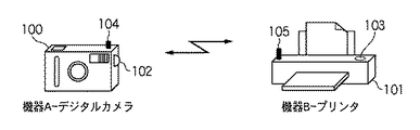
図1は、第1の実施形態における無線LANの構成の一例を示す図である。図1に示すように、無線通信機器AはIEEE802.11準拠の無線通信機能104を有するデジタルカメラ100であり、ユーザが通信パラメータ設定起動ボタン102を押下することにより通信パラメータ設定モードのネットワークを構成することが可能である。また、無線通信機器BはIEEE802.11準拠の無線通信機能105を有するプリンタ101であり、機器Aと同様に、ユーザが通信パラメータ設定起動ボタン103を押下することにより通信パラメータ設定モードのネットワークを構成することが可能である。
[First Embodiment]
FIG. 1 is a diagram illustrating an example of a configuration of a wireless LAN according to the first embodiment. As shown in FIG. 1, the wireless communication device A is a
次に、図2及び図3を用いて、通信パラメータ設定制御機能を有する機器A及び機器Bの構成及び動作について説明する。 Next, the configurations and operations of the devices A and B having the communication parameter setting control function will be described with reference to FIGS.
図2は、デジタルカメラ100(機器A)の構成の一例を示す概略ブロック図である。図2において、201はデジタルカメラ100を制御する制御部、202は画像処理部、203は制御命令(プログラム)や制御データが格納されているROM、204はRAMである。RAM204には、通信パラメータ設定用ネットワークを形成するための設定用通信パラメータが予め記憶されている。205は無線通信処理部であり、無線LANにおける通信制御を行う。206はアンテナ、207はアンテナ制御部である。
FIG. 2 is a schematic block diagram illustrating an example of the configuration of the digital camera 100 (device A). In FIG. 2, 201 is a control unit that controls the
208は撮像部であり、209のCCDから入力された画素信号を取り込む。210は撮像画像や設定情報を格納する記録メディアカードの制御を行うカードインタフェース、211は表示部である。212は操作部であり、撮影、再生、設定などを指示するボタンを含む。213は二次電池を含む電源部である。214は無線以外の通信インタフェース部であり、例えばUSBやIEEE1394などの有線インタフェースである。215は通信パラメータ設定ボタンであり、通信パラメータ設定起動を行う。
図3は、プリンタ101(機器B)の構成の一例を示す概略ブロック図である。図3において、301はプリンタ101を制御する制御部、302は画像処理部、303は制御命令(プログラム)や制御データが格納されているROM、304はRAM、305は電源部である。RAM304には、通信パラメータ設定用ネットワークを形成するための設定用通信パラメータが予め記憶されている。306は無線以外の通信インタフェース部であり、例えばUSBやIEEE1394などの有線インタフェースである。
FIG. 3 is a schematic block diagram illustrating an example of the configuration of the printer 101 (device B). In FIG. 3,
307はプリンタ用紙の給紙排紙を行う給紙排紙部である。308はプリンタエンジンであり、電子写真方式やインクジェット方式などの印字制御を行う。309は画像が格納された記録メディアカードの制御を行うカードインタフェース、310は表示部である。311は操作部であり、メニュー、設定などのボタンを含む。312は無線通信処理部であり、無線LANにおける通信制御を行う。313はアンテナ、314はアンテナ制御部である。315は通信パラメータ設定ボタンであり、通信パラメータ設定起動を行う。
次に、図4を用いて、IEEE802.11準拠の無線LANのアドホックネットワークにおける機器Aと機器Bとの間で無線パラメータのデータを設定する処理について説明する。 Next, a process of setting wireless parameter data between the devices A and B in the IEEE802.11 compliant wireless LAN ad hoc network will be described with reference to FIG.
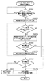
図4は、第1の実施形態における無線パラメータ設定シーケンスを示す図である。以下では、図4に示すように全体の流れを6つのステップに分け、それぞれのステップを順に説明する。 FIG. 4 is a diagram illustrating a wireless parameter setting sequence according to the first embodiment. Hereinafter, as shown in FIG. 4, the entire flow is divided into six steps, and each step will be described in order.
<通信パラメータ設定ネットワーク形成ステップ401>
ここでは、機器Aと機器Bの間で通信パラメータ設定用ネットワークをアドホック接続によって形成する処理を行う。
<Communication Parameter Setting
Here, processing for forming a communication parameter setting network between the devices A and B by ad hoc connection is performed.
<マスター機器決定ステップ402>
ここでは、機器Aと機器Bの間でどちらの機器が通信パラメータ設定用ネットワークのマスター機器となり、どちらの機器がスレーブ機器となるかを決定する処理と、各機器は相手が同一ネットワーク上に存在するか否かの監視処理を継続的に行う。
<Master
Here, the process of determining which device is the master device of the communication parameter setting network between device A and device B and which device is the slave device, and each device is on the same network The monitoring process of whether or not to perform is continuously performed.
<機器能力収集ステップ403>
ここでは、ステップ402で決定されたマスター機器が同一ネットワーク上に存在するスレーブ機器が所有している機器能力属性値をスレーブ機器に問い合わせて収集する処理を行う。
<Device
Here, the master device determined in
<通信パラメータ転送方向決定ステップ404>
ここでは、ステップ403でマスター機器が収集した各スレーブ機器の機器能力属性値と自マスター機器の機器能力属性値とを比較し、どの機器からどの機器へ通信パラメータの転送を行うかをマスター機器が決定し、かつ、各スレーブ機器に対して通信パラメータの転送を行う上で必要となる、あて先や発信元情報などの指示を転送する。
<Communication Parameter Transfer
Here, the master device compares the device capability attribute value of each slave device collected by the master device in
<通信パラメータ転送ステップ405>
ここでは、ステップ404で決定された通信パラメータの転送方向に従って実際に通信パラメータ提供能力を持つ機器から通信パラメータ受理能力を持つ機器へ通信パラメータを転送する。
<Communication
Here, the communication parameter is transferred from the device having the communication parameter providing capability to the device having the communication parameter receiving capability in accordance with the communication parameter transfer direction determined in
<通信パラメータ設定ネットワーク終了ステップ406>
ここでは、ステップ405の転送終了をきっかけに通信パラメータ設定ネットワークを終了するために必要となる処理を行う。尚、通信パラメータ設定ネットワーク終了ステップ406が終了した後は、通信パラメータ転送ステップ405において転送された通信パラメータを用いて新たなネットワークを構築することになる。
<Communication parameter setting
Here, processing necessary for terminating the communication parameter setting network is performed after the end of the transfer in
次に、上述した6つの通信パラメータ設定シーケンスで示す各ステップについて詳細に説明する。 Next, each step shown in the six communication parameter setting sequences described above will be described in detail.
まず、デジタルカメラ100とプリンタ101との間の通信パラメータ設定ネットワーク形成ステップ401について説明する。デジタルカメラ100(機器A)の通信パラメータ設定起動ボタン215と、プリンタ101(機器B)の通信パラメータ設定起動ボタン315とを押下することで、デジタルカメラ100とプリンタ101とで構成される通信パラメータ設定用アドホックネットワークを形成する。このネットワークは、RAM204、304に記憶されている設定用通信パラメータを用いて形成する。
First, the communication parameter setting
尚、以下に説明する各ステップの処理は、全てステップ401で形成したネットワーク上で通信を行うことにより遂行されるものである。
The processing of each step described below is performed by performing communication on the network formed in
次に、デジタルカメラ100とプリンタ101との間で行われるマスター機器決定ステップ402について、その詳細を説明する。
Next, the details of the master
まず、マスター機器決定ステップ402において、機器A及び機器B間で送受信されるメッセージのフォーマットについて、図5を参照しながら説明する。
First, in the master
図5に示すように、マスター機器決定ステップ402において、各機器間で送受信するメッセージには、少なくとも送受信元を示すアドレス情報(宛先MACアドレス501、送信元MACアドレス502)と、通信パラメータ設定制御機能における識別子(ID)を示すID情報503と、マスター機器決定ステップ402における各機器の存在時間(Expire Time)を示す存在時間情報とが含まれる。尚、存在時間情報の値が“0”である場合は、メッセージを送信した機器がネットワークから即座に離脱することを示す。
As shown in FIG. 5, in the master
次に、図6を参照しながらネットワーク参加時に各機器が行うマスター機器とスレーブ機器の決定処理手順について説明する。 Next, a master device and slave device determination processing procedure performed by each device when participating in the network will be described with reference to FIG.
図6は、ネットワーク参加時に各機器が行うマスター機器とスレーブ機器の決定処理を示すフローチャートである。 FIG. 6 is a flowchart showing master device and slave device determination processing performed by each device when participating in the network.
マスター機器決定ステップ402を開始後、ステップS601へ進み、機器はランダムタイマT1を起動する。このタイマT1により、この後の処理で行われる問合せメッセージの送信をランダム時間分だけ遅らせることで、複数の機器が、同時にマスター機器決定ステップ402を開始した場合に、メッセージの一斉送信によるメッセージの衝突を回避することができる。
After starting the master
次に、ステップS602において、機器はマスター機器の存在を通知するマスター宣言メッセージの受信を確認する。ここで、マスター宣言メッセージを受信した場合は、ネットワーク中に既にマスター機器が存在すると判断し、後述するステップS608へ進む。また、マスター宣言メッセージを受信していない場合はステップS603へ進み、タイマT1のタイムアップを確認する。タイマT1がタイムアップしていない場合はステップS602に戻り、マスター宣言メッセージを受信するか、或いはタイマT1がタイムアップするまで、上述した処理を繰り返す。この処理により、メッセージ衝突回避を目的としたランダム待ち時間中にマスター宣言メッセージを受信した場合でも、速やかにステップS608で説明するマスター宣言受信時の処理を行うことが可能となる。 Next, in step S602, the device confirms reception of a master declaration message notifying the presence of the master device. If a master declaration message is received, it is determined that a master device already exists in the network, and the process proceeds to step S608 described later. If the master declaration message has not been received, the process proceeds to step S603, and the timer T1 is confirmed to be up. If the timer T1 has not expired, the process returns to step S602, and the above-described processing is repeated until a master declaration message is received or the timer T1 expires. With this process, even when a master declaration message is received during a random waiting time for the purpose of message collision avoidance, it is possible to immediately perform the process at the time of receiving a master declaration, which will be described in step S608.
また、ステップS603で、タイマT1がタイムアップした場合はステップS604へ進み、機器はマスター機器の存在を問い合わせるマスター問合せメッセージをネットワークへブロードキャスト送信し、マスター問合せ送信タイマT2を起動する。このマスター問合せ送信タイマT2は、マスター問合せメッセージを一定間隔で送信するために用いられる。 If the timer T1 has expired in step S603, the process proceeds to step S604, where the device broadcasts a master inquiry message for inquiring about the presence of the master device to the network, and starts the master inquiry transmission timer T2. This master inquiry transmission timer T2 is used to transmit a master inquiry message at a constant interval.
次に、ステップS605において、機器はマスター宣言メッセージの受信を確認し、マスター宣言メッセージを受信した場合は、ネットワーク中に既にマスター機器が存在することを認識し、後述するステップS608へ進む。また、マスター宣言メッセージを受信していない場合はステップS606へ進み、タイマT2のタイムアップを確認する。タイマT2がタイムアップしていない場合はステップS605に戻り、マスター宣言メッセージを受信するか、或いはタイマT2がタイムアップするまで上述の処理を繰り返す。 Next, in step S605, the device confirms reception of the master declaration message. If the master declaration message is received, the device recognizes that the master device already exists in the network, and proceeds to step S608 described later. If the master declaration message has not been received, the process proceeds to step S606, and the timer T2 is checked for time-up. If the timer T2 has not expired, the process returns to step S605, and the above processing is repeated until a master declaration message is received or the timer T2 expires.
また、ステップS606で、タイマT2がタイムアップした場合はステップS607へ進み、機器はマスター問合せメッセージを所定回数送信したか否かを確認する。所定回数送信していない場合はステップS604に戻り、マスター問合せメッセージの送信が所定回数完了するか、或いはマスター宣言メッセージを受信するまで、ステップS604〜S607の処理を繰り返す。 If the timer T2 has expired in step S606, the process proceeds to step S607, and the device checks whether or not the master inquiry message has been transmitted a predetermined number of times. If it has not been transmitted a predetermined number of times, the process returns to step S604, and the processing of steps S604 to S607 is repeated until the transmission of the master inquiry message is completed a predetermined number of times or a master declaration message is received.
一方、機器がマスター宣言メッセージを受信した場合はステップS608へ進み、受信したメッセージよりマスター機器のMACアドレス501を取得し、RAMに記憶しているマスター機器管理テーブル(図19参照)に取得したMACアドレスを登録する。また、受信したメッセージの存在時間情報504よりマスター機器の存在時間を取得し、マスター機器存在タイマT7に取得した存在時間をセットしてタイマT7を起動する。タイマT7は、マスター機器がネットワークに存在している時間を確認するために用いられ、タイマT7がタイムアップした場合、機器はマスター機器がネットワークから離脱したと判断する。
On the other hand, when the device receives the master declaration message, the process proceeds to step S608, where the
ステップS608でタイマT7を起動後、ステップS623において、機器はランダムタイマT9を起動する。このタイマT9により、この後の処理で行われる問合せスレーブ宣言メッセージの送信をランダム時間分だけ遅らせることで、マスター宣言メッセージに対して複数の機器がスレーブ宣言メッセージを送信する場合の、スレーブ宣言メッセージの衝突を回避することができる。ランダムタイマT9を起動後ステップS624へ進み、タイマT9のタイムアップを待つ。 After starting the timer T7 in step S608, the device starts the random timer T9 in step S623. This timer T9 delays the transmission of the inquiry slave declaration message performed in the subsequent processing by a random time, so that the slave declaration message in the case where a plurality of devices transmit the slave declaration message to the master declaration message. Collisions can be avoided. After starting the random timer T9, the process proceeds to step S624 and waits for the timer T9 to expire.
その後、タイマT9がタイムアップするとステップS609へ進み、自機器がスレーブ機器であることを通知するスレーブ宣言メッセージをマスター機器へ送信する。そして、ステップS610において、機器はスレーブ宣言メッセージ送信用タイマT5を起動する。タイマT5は、スレーブ宣言メッセージの周期的な送信を行うために用いられ、タイマT5がタイムアップした際にスレーブ宣言メッセージを再送信する。ここで、タイマT5はスレーブ宣言メッセージに記述される存在期限時間よりも短い値に設定され、存在期限が切れないよう周期的にメッセージの送信を行う。タイマT5を起動後、機器は後述するスレーブ機器の動作を行う。 Thereafter, when the timer T9 expires, the process proceeds to step S609, and a slave declaration message notifying that the own device is a slave device is transmitted to the master device. In step S610, the device activates a slave declaration message transmission timer T5. The timer T5 is used for periodically transmitting the slave declaration message, and retransmits the slave declaration message when the timer T5 times out. Here, the timer T5 is set to a value shorter than the existence expiration time described in the slave declaration message, and periodically transmits the message so that the existence expiration does not expire. After starting the timer T5, the device operates as a slave device described later.
また、上述のステップS607で、マスター問合せメッセージを所定回数送信完了した場合はステップS611へ進み、機器はマスター宣言メッセージ受信用タイマT3を起動する。そして、機器はタイマT3がタイムアップするまで他の機器からメッセージを受信するのを待ち、メッセージを受信すると、メッセージの種類に応じて以下に説明する処理を行う。 If the master inquiry message has been transmitted a predetermined number of times in step S607 described above, the process proceeds to step S611, and the device activates a master declaration message reception timer T3. Then, the device waits to receive a message from another device until the timer T3 expires, and when the message is received, performs the processing described below according to the type of the message.
ステップS612において、機器はマスター宣言メッセージの受信を確認し、マスター宣言メッセージを受信した場合は、ネットワーク中に既にマスター機器が存在することを認識してステップS608へ進む。また、メッセージを受信していない場合はステップS613へ進む。 In step S612, the device confirms reception of the master declaration message. When the master declaration message is received, the device recognizes that the master device already exists in the network and proceeds to step S608. If no message has been received, the process proceeds to step S613.
ステップS613において、機器はマスター問合せメッセージの受信を確認し、マスター問合せメッセージを受信した場合は、ネットワーク中にマスター機器が存在せず、かつ自機器以外にマスター機器になり得る機器が存在する、マスター問合せ衝突状態であると判定してステップS614へ進み、マスター衝突解決処理を行う。また、マスター問合せメッセージを受信していない場合はステップS615へ進む。 In step S613, the device confirms reception of the master inquiry message. If the master inquiry message is received, there is no master device in the network, and there is a device that can be a master device other than the own device. It determines with it being an inquiry collision state, it progresses to step S614, and master collision solution processing is performed. If no master inquiry message has been received, the process advances to step S615.
ステップS614で、機器はマスター問合せ衝突状態を解決するマスター衝突解決処理を行う。ここでは、受信したマスター問合せメッセージの送信元MACアドレス502と、自機器のMACアドレスとを辞書式順序で比較する。比較の結果、自機器のMACアドレスが辞書式順序で小さかった場合はWinnerと判定し、自機器のMACアドレスが辞書式順序で大きかった場合は判定Loserと判定する。そして、判定結果を記憶し、詳細は後述するステップS617において判定結果を利用した処理を行う。
In step S614, the device performs a master collision resolution process that resolves the master inquiry collision state. Here, the
尚、3台以上の機器がマスター機器決定ステップ402の処理を行っている場合、各々の機器はマスター宣言受信タイマT3がタイムアップするまでに複数の機器とステップS614で説明したマスター衝突解決処理を行うことが考えられるが、この場合、一度でもLoserと判定すると、その判定結果をLoserと記憶し、また全てのマスター衝突解決処理においてWinnerと判定した場合にのみ、その判定結果をWinnerと記憶する。
When three or more devices are performing the master
次に、ステップS615において、機器はマスター宣言受信タイマT3のタイムアップを確認する。タイマT3がタイムアップした場合、機器はネットワーク内にマスター機器が存在しない状態であると判断してステップS616へ進む。また、タイマT3がタイムアップしていない場合はステップS612に戻る。 Next, in step S615, the device confirms that the master declaration reception timer T3 has expired. If the timer T3 has expired, the device determines that there is no master device in the network and proceeds to step S616. If the timer T3 has not expired, the process returns to step S612.
ステップS616において、機器はマスター宣言受信タイマT3がタイムアップするまでにマスター衝突解決処理を行ったか否かを確認する。ここで、マスター衝突解決処理を行っていた場合はステップS617へ進み、行っていなかった場合はステップS618へ進む。 In step S616, the device confirms whether or not the master collision resolution processing has been performed before the master declaration reception timer T3 expires. If the master collision resolution process has been performed, the process proceeds to step S617. If not, the process proceeds to step S618.
ステップS617において、機器はマスター衝突解決処理における判定結果を確認する。判定結果がWinnerであった場合はステップS618へ進み、判定結果がLoserであった場合はステップS620へ進む。 In step S617, the device confirms the determination result in the master collision resolution process. If the determination result is Winner, the process proceeds to step S618, and if the determination result is Loser, the process proceeds to step S620.
ステップS618において、機器は自機器がマスター機器であることを通知するマスター宣言メッセージをネットワークへブロードキャスト送信する。 In step S618, the device broadcasts to the network a master declaration message notifying that the device is the master device.
ステップS619において、機器はマスター宣言メッセージ送信タイマT4を起動する。タイマT4は、マスター宣言メッセージの周期的な送信を行うために用いられ、タイマT4がタイムアップした際にはマスター宣言メッセージを再送信する。ここでタイマT4はマスター宣言メッセージに記述される存在期限時間よりも短い値に設定され、存在期限が切れないよう周期的にメッセージの送信を行う。タイマT4を起動後、機器は後述するマスター機器の動作を行う。 In step S619, the device starts a master declaration message transmission timer T4. The timer T4 is used to periodically transmit the master declaration message, and retransmits the master declaration message when the timer T4 expires. Here, the timer T4 is set to a value shorter than the existence expiration time described in the master declaration message, and periodically transmits a message so that the existence expiration does not expire. After starting the timer T4, the device operates the master device described later.
ステップS620において、機器はマスター宣言受信待ちタイマT8を起動する。このタイマT8は、上述したステップS617の判定でLoserとなった機器がWinnerとなった機器からのマスター宣言メッセージの受信を一定期間待つために用いられる。 In step S620, the device activates a master declaration reception waiting timer T8. The timer T8 is used to wait for a certain period of time when the device that has become Loser in the determination in step S617 described above receives a master declaration message from the device that has become a winner.
ステップS621において、機器はマスター宣言メッセージの受信を確認し、マスター宣言メッセージを受信した場合は上述したステップS608へ進む。また、マスター宣言メッセージを受信しなかった場合はステップS622へ進む。ステップS622において、機器はマスター宣言受信待ちタイマT8のタイムアップを確認する。ここでタイマT8がタイムアップした場合、機器は期間内にマスター機器からのメッセージを受け取ることができなかったとしてエラー終了する。また、タイマT8がタイムアップしていない場合はステップS621に戻る。 In step S621, the device confirms reception of the master declaration message. If a master declaration message is received, the device proceeds to step S608 described above. If the master declaration message has not been received, the process proceeds to step S622. In step S622, the device confirms that the master declaration reception waiting timer T8 has expired. Here, when the timer T8 expires, the device ends in error because it cannot receive the message from the master device within the period. If the timer T8 has not expired, the process returns to step S621.
尚、ステップS622において、タイマT8がタイムアップした場合はエラー終了しているが、タイマT8がタイムアップした場合にステップS601に戻り、マスター問合せメッセージを再送信しても良い。このように処理することにより、期間内にマスター機器からメッセージを受け取ることができなかった場合でも、マスター機器とスレーブ機器の決定処理を速やかに再試行することが可能となる。 In step S622, if the timer T8 times out, the error ends. However, if the timer T8 times out, the process may return to step S601 to retransmit the master inquiry message. By processing in this way, even if a message cannot be received from the master device within the period, it is possible to quickly retry the determination process of the master device and the slave device.
また、図6に示すマスター機器とスレーブ機器の決定処理において、ステップS604のマスター問合せメッセージの送信が完了するまでに、他の機器からマスター問合せメッセージを受信した場合は、ステップS614のマスター衝突解決処理を行い、判定結果がLoserであれば、その後、マスター問合せメッセージの送信を行わなくても良い。これにより、ネットワークへの無駄なメッセージの送信を抑えることが可能となる。 In the master device / slave device determination process shown in FIG. 6, if a master inquiry message is received from another device before the transmission of the master inquiry message in step S604 is completed, a master collision resolution process in step S614 is performed. If the determination result is Loser, the master inquiry message need not be transmitted thereafter. Thereby, it is possible to suppress transmission of useless messages to the network.
以上の手順をもって、マスター機器とスレーブ機器の決定処理が行われる。 With the above procedure, the master device and the slave device are determined.
次に、図7〜図12を参照しながらマスター機器決定ステップ402におけるマスター機器の動作について説明する。
Next, the operation of the master device in the master
マスター機器は、ネットワークの他の機器からメッセージを受信した場合や、マスター機器内部のタイマがタイムアップした場合に、各々の状態に応じて以下に説明する処理を行う。 When the master device receives a message from another device on the network or when the timer in the master device times out, the master device performs the processing described below according to each state.
まず、マスター機器がネットワーク内の他の機器よりマスター問合せメッセージを受信した場合に行う、マスター問合せメッセージ応答処理について説明する。 First, a master inquiry message response process performed when the master device receives a master inquiry message from another device in the network will be described.
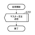
図7は、マスター問合せメッセージへの応答処理を示すフローチャートである。マスター機器は処理開始後、ステップS701において、マスター宣言メッセージをマスター問合せメッセージの送信元の機器へ送信する。そして、このメッセージを送信後、マスター機器はマスター問合せメッセージ応答処理を終了する。 FIG. 7 is a flowchart showing a response process to the master inquiry message. After starting the processing, the master device transmits a master declaration message to the source device of the master inquiry message in step S701. Then, after transmitting this message, the master device ends the master inquiry message response process.
尚、ステップS701において、マスター問合せメッセージの応答としてマスター宣言メッセージを送信する場合、上述のようにメッセージの送信元の機器へユニキャスト送信を行う方法とは別に、マスター宣言メッセージをブロードキャスト送信する方法も考えられる。前者の方法は無駄の無いメッセージ送信を行える利点があるが、後者の方法は複数の機器へ一度にマスター宣言メッセージを送信できるため、複数の機器がマスター問合せの状態であった場合に、効率良くマスター宣言メッセージを送信できるという利点がある。このように、2つの方法はそれぞれ異なる利点を有しており、ここではマスター問合せメッセージの応答としてのマスター宣言メッセージの送信方法について、限定は行わず、どちらの方法を用いても良いものとする。 In addition, when transmitting a master declaration message as a response to the master inquiry message in step S701, a method of broadcasting a master declaration message separately from the method of performing unicast transmission to the message transmission source device as described above. Conceivable. The former method has the advantage that a message can be sent without waste, but the latter method can send a master declaration message to multiple devices at once, so it is efficient when multiple devices are in the master inquiry state. There is an advantage that a master declaration message can be transmitted. As described above, the two methods have different advantages, and here, there is no limitation on the method of transmitting the master declaration message as a response to the master inquiry message, and either method can be used. .
次に、上述したステップS619又は後述するステップS802で起動されたマスター宣言メッセージ送信用タイマT4がタイムアップした場合にマスター機器が行う、マスター宣言メッセージ定期送信処理について説明する。 Next, master declaration message regular transmission processing performed by the master device when the master declaration message transmission timer T4 activated in step S619 described above or in step S802 described later expires will be described.
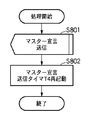
図8は、マスター宣言メッセージ定期送信処理を示すフローチャートである。処理開始後、マスター機器はステップS801においてマスター宣言メッセージをネットワークへブロードキャスト送信を行う。そして、メッセージを送信後、ステップS802においてマスター宣言メッセージ送信用タイマT4をマスター機器の存在時間よりも短い値に設定して再起動する。タイマ再起動後、マスター機器はマスター宣言メッセージ定期送信処理を終了する。 FIG. 8 is a flowchart showing master declaration message regular transmission processing. After starting the processing, the master device broadcasts a master declaration message to the network in step S801. Then, after transmitting the message, in step S802, the master declaration message transmission timer T4 is set to a value shorter than the existence time of the master device and restarted. After the timer is restarted, the master device ends the master declaration message periodic transmission process.
次に、マスター機器がスレーブ宣言メッセージを受信した場合に行う、スレーブ機器管理処理について説明する。 Next, a slave device management process performed when the master device receives a slave declaration message will be described.
図9は、スレーブ機器管理処理を示すフローチャートである。処理開始後、マスター機器はステップS901においてスレーブ宣言メッセージの存在時間情報504に記述されている存在時間の値を参照し、その値が“0”か否かを確認する。ここで、存在時間の値が“0”であった場合には、マスター機器はスレーブ宣言メッセージを送信したスレーブ機器がネットワークから離脱すると判断してステップS902へ進み、また、存在時間の値が“0”ではなかった場合には、ステップS903へ進む。
FIG. 9 is a flowchart showing slave device management processing. After starting the processing, the master device refers to the value of the existence time described in the
ステップS903において、マスター機器は受信したスレーブ宣言メッセージの送信元MACアドレス502がRAMに記憶しているスレーブ機器管理テーブル(図10参照)に登録されているか否かを確認する。図10に示すスレーブ機器管理テーブルは、マスター機器がネットワークに参加中のスレーブ機器を把握するために、スレーブ機器のMACアドレスをインデックス番号で登録したテーブルである。
In step S903, the master device checks whether or not the
ここで、送信元MACアドレスがテーブルに登録されていなかった場合、マスター機器はスレーブ宣言メッセージを送信したスレーブ機器がネットワークに参加したと判断してステップS904へ進む。また、送信元MACアドレスがテーブルに登録されていた場合、マスター機器はスレーブ機器の存在時間の更新を行うためにステップS905へ進む。 If the source MAC address is not registered in the table, the master device determines that the slave device that transmitted the slave declaration message has joined the network, and proceeds to step S904. If the source MAC address is registered in the table, the master device proceeds to step S905 in order to update the existing time of the slave device.
ステップS904において、マスター機器は受信したスレーブ宣言メッセージの送信元MACアドレス502をスレーブ機器管理テーブルに登録する。そして、マスター機器は登録したスレーブ機器のテーブルにおけるインデックス番号nに対応するスレーブ機器存在タイマT6nに上述のステップS901で参照した存在時間をセットしてタイマを起動する。タイマT6は、スレーブ機器管理テーブルに登録されたスレーブ機器の台数分だけ起動され、タイマT6nがタイムアップした場合、マスター機器は対応するスレーブ機器がネットワークから離脱したと判断する。
In step S904, the master device registers the
また、ステップS905において、マスター機器はスレーブ宣言メッセージを送信したスレーブ機器に対応するスレーブ機器存在タイマT6nのタイマ値を、上述のステップS901で参照した存在時間に更新してタイマを再起動する。 In step S905, the master device updates the timer value of the slave device existence timer T6n corresponding to the slave device that transmitted the slave declaration message to the existence time referred to in step S901, and restarts the timer.
一方、ステップS902において、マスター機器はスレーブ宣言メッセージを送信したスレーブ機器に対応するインデックス番号nのスレーブ機器のMACアドレスをスレーブ機器管理テーブルから削除する。 On the other hand, in step S902, the master device deletes the MAC address of the slave device with the index number n corresponding to the slave device that transmitted the slave declaration message from the slave device management table.
以上の手順をもって、マスター機器のスレーブ機器管理処理が行われる。 With the above procedure, the slave device management process of the master device is performed.
ここで、上述のステップS904又はステップS905で起動されたスレーブ機器存在タイマT6nがタイムアップした場合にマスター機器が行う、スレーブ機器離脱時処理について説明する。 Here, a slave device leaving process performed by the master device when the slave device presence timer T6n started in step S904 or step S905 described above is up will be described.
図11は、スレーブ機器離脱時処理を示すフローチャートである。処理開始後、マスター機器はステップS1101においてタイムアップしたタイマに対応するスレーブ機器がネットワークから離脱したと判断し、スレーブ機器管理テーブルにおけるタイムアップしたタイマに対応するインデックス番号nのスレーブ機器のMACアドレスをテーブルから削除する。削除後、マスター機器はスレーブ機器離脱時処理を終了する。 FIG. 11 is a flowchart showing processing when a slave device leaves. After starting the processing, the master device determines that the slave device corresponding to the timer timed up in step S1101 has left the network, and sets the MAC address of the slave device with the index number n corresponding to the timed up timer in the slave device management table. Delete from the table. After the deletion, the master device ends the process when the slave device leaves.
次に、ユーザ操作や上位アプリケーション等からの指示によって機器がマスター機器としての動作を正常終了する場合にマスター機器が行う、マスター機器終了時処理について説明する。 Next, a master device termination process performed by the master device when the device normally terminates the operation as the master device by an instruction from a user operation or a higher-level application will be described.
図12は、マスター機器終了時処理を示すフローチャートである。処理開始後、マスター機器はステップS1201において存在時間情報504に“0”を記述したマスター宣言メッセージをブロードキャスト送信する。このメッセージ送信により、マスター機器が離脱することをスレーブ機器に通知する。そして、このメッセージを送信後、ステップS1202においてスレーブ機器存在タイマT6を停止した後に、スレーブ機器管理テーブルを破棄し、またマスター宣言メッセージ送信タイマT4を停止することで、マスター宣言メッセージの定期送信を終了し、マスター機器の動作を終了する。
FIG. 12 is a flowchart showing the master device termination process. After starting the process, the master device broadcasts a master declaration message in which “0” is described in the
以上の手順をもって、マスター機器決定ステップ402におけるマスター機器の動作が行われる。
With the above procedure, the operation of the master device in the master
ここまで説明したように、第1の実施形態ではネットワークに参加した機器がマスター問合せメッセージを送信し(ステップS604)、マスター宣言メッセージの受信を確認する(ステップS605)。一方、マスター機器はマスター問合せメッセージを受信すると直ちにマスター宣言メッセージを送信する(ステップS701)。 As described so far, in the first embodiment, a device participating in the network transmits a master inquiry message (step S604) and confirms reception of a master declaration message (step S605). On the other hand, the master device transmits a master declaration message immediately after receiving the master inquiry message (step S701).
これにより、マスター機器がネットワークに存在する場合は、ネットワークに参加した機器が定期的にメッセージの受信を確認してからメッセージを送信する方式よりも速やかにマスター機器を検知することが可能となる。 Thereby, when the master device exists in the network, it becomes possible to detect the master device more quickly than a method in which a device participating in the network periodically confirms reception of a message and then transmits a message.
また、上述した存在時間情報504を利用した機器管理処理により、機器は存在時間を“0”に設定されたメッセージを受信することで機器の離脱を検知可能となり、一定期間毎に確認を行うよりも迅速に機器状態を把握することが可能となる。
In addition, the device management process using the above-described
次に、図13〜図16を参照しながらマスター機器決定ステップ402におけるスレーブ機器の動作について説明する。
Next, the operation of the slave device in the master
スレーブ機器は、マスター機器からメッセージを受信した場合や、スレーブ機器内部のタイマがタイムアップした場合に、各々の状態に応じて以下に説明する処理を行う。 When the slave device receives a message from the master device or when the timer in the slave device times out, the slave device performs processing described below according to each state.
まず、上述のステップS610又は後述するステップS1302で起動されたスレーブ宣言メッセージ送信用タイマT5がタイムアップした場合にスレーブ機器が行う、スレーブ宣言メッセージ定期送信処理について説明する。 First, the slave declaration message regular transmission process performed by the slave device when the slave declaration message transmission timer T5 activated in step S610 described above or step S1302 described later expires will be described.
図13は、スレーブ宣言メッセージ定期送信処理を示すフローチャートである。処理開始後、スレーブ機器はステップS1301においてスレーブ宣言メッセージをマスター機器へ送信し、メッセージを送信後、ステップS1302においてスレーブ宣言メッセージ送信用タイマT5をスレーブ機器の存在時間よりも短い値に設定して再起動する。そして、タイマ再起動後、スレーブ機器はスレーブ宣言メッセージ定期送信処理を終了する。 FIG. 13 is a flowchart showing slave declaration message regular transmission processing. After the start of processing, the slave device transmits a slave declaration message to the master device in step S1301, and after transmitting the message, in step S1302, the slave declaration message transmission timer T5 is set to a value shorter than the existing time of the slave device and restarted. to start. Then, after restarting the timer, the slave device ends the slave declaration message regular transmission processing.
次に、スレーブ機器がマスター宣言メッセージを受信した場合に行う、マスター機器管理処理について説明する。 Next, a master device management process performed when the slave device receives a master declaration message will be described.
図14は、マスター機器管理処理を示すフローチャートである。処理開始後、スレーブ機器はステップS1401においてマスター宣言メッセージ中の存在時間情報504に記述されている存在時間の値を参照し、存在時間の値が“0”か否かを確認する。存在時間の値が“0”であれば、スレーブ機器はマスター機器がネットワークから離脱すると判断してステップS1403へ進み、存在時間の値が“0”でなければ、ステップS1402へ進む。
FIG. 14 is a flowchart showing master device management processing. After starting the processing, the slave device refers to the value of the existence time described in the
ステップS1402において、スレーブ機器はマスター機器存在タイマT7のタイマ値を上述のステップS1401で参照した存在時間に更新してタイマを再起動する。 In step S1402, the slave device updates the timer value of the master device existence timer T7 to the existence time referred to in step S1401, and restarts the timer.
ステップS1403において、スレーブ機器はマスター機器存在タイマT7を停止後にマスター機器管理テーブルを破棄する。また、スレーブ宣言メッセージ送信用タイマT5を停止することでスレーブ宣言メッセージの定期送信を終了し、スレーブ機器の動作を終了する。 In step S1403, the slave device discards the master device management table after stopping the master device presence timer T7. Further, by stopping the slave declaration message transmission timer T5, the regular transmission of the slave declaration message is terminated, and the operation of the slave device is terminated.
以上の手順をもって、マスター機器管理処理が行われる。 The master device management process is performed according to the above procedure.
次に、上述のステップS608又はステップS1402で起動されたマスター機器存在タイマT7がタイムアップした場合にスレーブ機器が行う、マスター機器離脱時処理について説明する。 Next, a master device leaving process performed by the slave device when the master device presence timer T7 activated in step S608 or S1402 described above is up will be described.
図15は、マスター機器離脱時処理を示すフローチャートである。処理開始後、スレーブ機器はステップS1501において、マスター機器存在タイマT7を停止後にマスター管理テーブルを破棄する。また、スレーブ宣言メッセージ送信用タイマT5を停止することでスレーブ宣言メッセージの定期送信を終了し、スレーブ機器の動作を終了する。 FIG. 15 is a flowchart showing processing when the master device leaves. After starting the processing, in step S1501, the slave device discards the master management table after stopping the master device existence timer T7. Further, by stopping the slave declaration message transmission timer T5, the regular transmission of the slave declaration message is terminated, and the operation of the slave device is terminated.
次に、ユーザ操作や上位アプリケーション等からの指示によってスレーブ機器の動作を正常終了する場合にスレーブ機器が行う、スレーブ機器終了時処理について説明する。 Next, a slave device termination process performed by the slave device when the operation of the slave device is normally terminated by an instruction from a user operation or a higher-level application will be described.
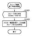
図16は、スレーブ機器終了時処理を示すフローチャートである。処理開始後、スレーブ機器はステップS1601において、存在時間情報504に“0”を記述したスレーブ宣言メッセージをマスター機器へ送信する。このメッセージ送信により、スレーブ機器が離脱することをマスター機器に通知する。このメッセージ送信後、ステップS1602において、マスター機器存在タイマT7を停止後にマスター機器管理テーブルを破棄する。また、スレーブ宣言メッセージ送信タイマT5を停止することでスレーブ宣言メッセージの定期送信を終了し、スレーブ機器の動作を終了する。
FIG. 16 is a flowchart showing the slave device termination process. After starting the processing, in step S1601, the slave device transmits a slave declaration message in which “0” is described in the
尚、上述のステップS1403及びステップS1501において、スレーブ機器の動作を終了した後、機器は図6に示すマスター機器とスレーブ機器の決定処理を再試行しても良い。これにより、例えば3台以上の機器間で無線パラメータ自動設定を行っている際にマスター機器が終了した場合でも、残った機器の間で速やかにマスター機器決定ステップ402を再開し、無線パラメータ自動設定処理を行うことが可能となる。
In step S1403 and step S1501, the device may retry the master device / slave device determination process shown in FIG. 6 after the operation of the slave device is completed. Thereby, for example, even when the master device is terminated when wireless parameter automatic setting is performed among three or more devices, the master
以上の手順をもって、マスター機器決定ステップ402におけるスレーブ機器の動作が行われる。
With the above procedure, the operation of the slave device in the master
次に、図1に示すデジタルカメラ100(機器A)とプリンタ101(機器B)が図5〜図16を用いて説明したマスター機器決定ステップ402において、マスター機器決定を行う際の動作について、図17、図18を用いて詳細に説明する。
Next, the operations when the digital camera 100 (device A) and the printer 101 (device B) shown in FIG. 1 perform master device determination in the master
まず、ネットワーク内にマスター機器が存在せず、機器Aが処理を開始した後に機器Bが処理を開始し、機器間でマスター機器とスレーブ機器を決定する際の動作について説明する。 First, the operation when the master device does not exist in the network, the device B starts processing after the device A starts processing, and determines the master device and the slave device between the devices will be described.
図17は、機器Aが処理を開始した後に機器Bが処理を開始した場合のマスター機器とスレーブ機器とを決定するシーケンスを示す図である。 FIG. 17 is a diagram illustrating a sequence for determining a master device and a slave device when device B starts processing after device A starts processing.
機器Aが処理を開始した後、マスター問合せ起動時間(TH1700)の間、ランダムタイマT1を起動してメッセージの送信を待機する(S601、S602、S603の処理に相当)。これは、ステップS601で説明したように、複数の機器が同時にマスター機器決定ステップ402を開始した際に、メッセージの一斉送信によるメッセージ衝突を回避するために行われる。
After the device A starts processing, during the master inquiry activation time (TH1700), the random timer T1 is activated to wait for message transmission (corresponding to the processing of S601, S602, and S603). As described in step S601, this is performed in order to avoid message collision due to simultaneous transmission of messages when a plurality of devices starts the master
その後、ランダムタイマT1がタイムアップすると、機器Aはマスター問合せ送信タイマT2にマスター問合せ送信間隔(TH1701)を設定して起動して、マスター問合せ送信タイマT2のタイムアップ毎にマスター問合せメッセージを送信する(S604、S605、S606、S607の処理に相当)。この例の場合、マスター問合せメッセージの送信を3回行う(F1702、F1703、F1704)。 Thereafter, when the random timer T1 expires, the device A starts by setting the master inquiry transmission timer T2 to the master inquiry transmission interval (TH1701), and transmits a master inquiry message every time the master inquiry transmission timer T2 times out. (Corresponding to the processing of S604, S605, S606, S607). In this example, the master inquiry message is transmitted three times (F1702, F1703, F1704).
機器Aはマスター問合せメッセージを送信した後、マスター宣言受信タイマT3を起動し、マスター問合せ応答待ち時間(TH1705)の間にマスター宣言メッセージを受信するのを待つ(S611、S612、S613、S615の処理に相当)。この例の場合、機器Aは所定時間(TH1705)の間にメッセージを受信しないため、マスター宣言受信タイマT3のタイムアップ後に、マスター宣言メッセージのブロードキャスト送信(F1706)を行い、機器Aがマスター機器であることを他の機器に通知する(S616、S618の処理に相当)。 After transmitting the master inquiry message, the device A starts the master declaration reception timer T3 and waits to receive the master declaration message during the master inquiry response waiting time (TH1705) (processing of S611, S612, S613, and S615) Equivalent). In this example, since device A does not receive a message during a predetermined time (TH1705), after the master declaration reception timer T3 expires, broadcast transmission of a master declaration message (F1706) is performed, and device A is the master device. This is notified to other devices (corresponding to the processing of S616 and S618).
マスター宣言メッセージを送信後、機器Aはマスター宣言送信タイマT4にマスター宣言送信間隔(TH1707)を設定して起動し、マスター宣言送信タイマT4のタイムアップ毎に周期的にマスター宣言メッセージをブロードキャスト送信(F1708)を行う(S619、S801、S802の処理に相当)。 After transmitting the master declaration message, the device A starts by setting a master declaration transmission interval (TH1707) in the master declaration transmission timer T4, and periodically transmits the master declaration message every time the master declaration transmission timer T4 expires ( F1708) (corresponding to the processes of S619, S801, and S802).
図17に示す例では、機器Aがマスター宣言メッセージの定期送信開始後(F1706とF1708の間)に機器Bの処理が開始される。 In the example illustrated in FIG. 17, the processing of the device B is started after the device A starts the regular transmission of the master declaration message (between F1706 and F1708).
機器Bが処理を開始した後、マスター問合せ起動時間(TH1709)の間、ランダムタイマT1を起動してメッセージの送信を待機する。ランダムタイマT1がタイムアップした後、機器Bはマスター問合せ送信タイマT2にマスター問合せ送信間隔(TH1710)を設定して起動し、マスター問合せ送信タイマT2のタイムアップ毎にマスター問合せメッセージを3回送信する(F1711、F1712、F1713)。 After the device B starts processing, during the master inquiry activation time (TH1709), the random timer T1 is activated to wait for message transmission. After the random timer T1 expires, the device B starts by setting the master inquiry transmission timer T2 to the master inquiry transmission interval (TH1710), and transmits the master inquiry message three times every time the master inquiry transmission timer T2 expires. (F1711, F1712, F1713).
これにより、機器Aが機器Bからのマスター問合せメッセージ(F1711)に応答し、マスター宣言メッセージを機器Bへ送信(F1714)する(S701の処理に相当)。機器Bはマスター問合せメッセージを送信後にマスター宣言受信タイマを起動し、マスター問合せ応答待ち時間(TH1715)の間にメッセージが送信されるのを待つ。 Thereby, the device A responds to the master inquiry message (F1711) from the device B, and transmits a master declaration message to the device B (F1714) (corresponding to the processing of S701). Device B starts the master declaration reception timer after transmitting the master inquiry message, and waits for the message to be transmitted during the master inquiry response waiting time (TH1715).
図17に示す例では、機器Bは所定時間(TH1715)の間に、機器Aよりマスター宣言メッセージを受信するため、機器Aがマスター機器であることを検知する。そして、マスター機器管理テーブル(図19)に機器AのMACアドレスを登録し、マスター機器存在タイマT7にマスター宣言メッセージより取得した機器Aの存在時間を設定してタイマを起動し、機器Aへスレーブ宣言メッセージを送信(F1716)する(S608、S609の処理に相当)。 In the example shown in FIG. 17, since device B receives a master declaration message from device A during a predetermined time (TH1715), it detects that device A is a master device. Then, the MAC address of the device A is registered in the master device management table (FIG. 19), the device A existence time acquired from the master declaration message is set in the master device existence timer T7, the timer is started, and the device A is slaved. A declaration message is transmitted (F1716) (corresponding to the processing of S608 and S609).
一方、機器Aが機器Bのスレーブ宣言メッセージを受信すると、スレーブ機器管理テーブル(図10)に機器BのMACアドレスを登録し、機器Bのスレーブ機器存在タイマT6にスレーブ宣言メッセージより取得した機器Bの存在時間を設定してタイマを起動する(S901、S903、S904の処理に相当)。 On the other hand, when the device A receives the slave declaration message of the device B, the MAC address of the device B is registered in the slave device management table (FIG. 10), and the device B acquired from the slave declaration message in the slave device existence timer T6 of the device B And the timer is started (corresponding to the processing of S901, S903, and S904).
機器Bが、スレーブ宣言メッセージを送信後、スレーブ宣言送信タイマT5にスレーブ宣言送信間隔(TH1717)を設定して起動し、スレーブ宣言送信タイマT5のタイムアップ毎に周期的にスレーブ宣言メッセージを機器Aへ送信(F1718)する(S610、S1301、S1302の処理に相当)。 After the device B transmits the slave declaration message, the device B is started by setting the slave declaration transmission interval (TH1717) in the slave declaration transmission timer T5, and periodically sends the slave declaration message to the device A every time the slave declaration transmission timer T5 times out. (F1718) (corresponding to the processing of S610, S1301, and S1302).
これ以降、機器Aと機器Bは宣言送信タイマに従って周期的に宣言メッセージを送信し、宣言メッセージを受信すると、メッセージ中の存在時間に存在タイマを再設定して再起動する(S905、S1402の処理に相当)。 Thereafter, device A and device B periodically transmit a declaration message according to the declaration transmission timer, and upon receiving the declaration message, reset the presence timer to the existing time in the message and restart (S905 and S1402) Equivalent).
以上の手順をもって、図17に示すシーケンスに従ってマスター機器とスレーブ機器が決定される。 With the above procedure, the master device and the slave device are determined according to the sequence shown in FIG.
次に、ネットワーク内にマスター機器が存在せず、機器Aと機器Bがほぼ同時に処理を開始し、機器間でマスター機器とスレーブ機器を決定する際の動作について説明する。 Next, the operation when the master device does not exist in the network, the devices A and B start processing almost simultaneously, and the master device and the slave device are determined between the devices will be described.
また、この例では、機器AのMACアドレスが機器BのMACアドレスよりも辞書式順序が小さく、機器Aがマスター衝突解決処理においてWinnerと判定されるものとする。 Further, in this example, it is assumed that the MAC address of the device A has a lexicographic order smaller than the MAC address of the device B, and the device A is determined to be a winner in the master collision resolution process.
図18は、機器Aと機器Bがほぼ同時に処理を開始した場合のマスター機器とスレーブ機器を決定するシーケンスを示す図である。 FIG. 18 is a diagram illustrating a sequence for determining a master device and a slave device when the devices A and B start processing almost simultaneously.
機器Aが処理を開始した後、マスター問合せ起動時間(TH1800)の間、ランダムタイマT1を起動してメッセージの送信を待機する。 After the device A starts processing, during the master inquiry activation time (TH1800), the random timer T1 is activated to wait for message transmission.
その後、ランダムタイマT1がタイムアップすると、機器Aはマスター問合せ送信タイマT2にマスター問合せ送信間隔(TH1801)を設定して起動して、マスター問合せ送信タイマT2のタイムアップ毎にマスター問合せメッセージを送信する。この例の場合、マスター問合せメッセージの送信を3回行う(F1802、F1803、F1804)。 Thereafter, when the random timer T1 expires, the device A starts by setting the master inquiry transmission interval (TH1801) in the master inquiry transmission timer T2, and transmits a master inquiry message every time the master inquiry transmission timer T2 times out. . In this example, the master inquiry message is transmitted three times (F1802, F1803, F1804).
また機器Aと同時に、機器Bも処理を開始後、マスター問合せ起動時間(TH1805)の間、ランダムタイマT1を起動してメッセージの送信を待機する。 At the same time as the device A, the device B also starts processing, and then activates the random timer T1 during the master inquiry activation time (TH1805) to wait for message transmission.
その後、ランダムタイマT1がタイムアップすると、機器Bはマスター問合せ送信タイマT2にマスター問合せ送信間隔(TH1806)を設定して起動して、マスター問合せ送信タイマT2のタイムアップ毎にマスター問合せメッセージを3回送信する(F1807、F1808、F1809)。 After that, when the random timer T1 expires, the device B sets the master inquiry transmission timer T2 with the master inquiry transmission interval (TH1806) and starts up, and the master inquiry message is sent three times every time the master inquiry transmission timer T2 expires. Transmit (F1807, F1808, F1809).
機器Aはマスター問合せメッセージを送信した後、マスター宣言受信タイマT3を起動し、マスター問合せ応答待ち時間(TH1810)の間にメッセージを受信するのを待つ。この例の場合、機器Aは所定時間(TH1810)の間に、機器Bよりマスター問合せメッセージを受信するため、マスター衝突解決処理を行う(S613、S614)。ここでは、機器Aがマスター衝突解決処理においてWinner判定されるため、機器Aはマスター宣言受信タイマT3のタイムアップ後、マスター衝突解決処理においてWinner判定されたことを認識する(S617の処理に相当)。そして、マスター宣言メッセージのブロードキャスト送信を行うことで機器Aがマスター機器であることを機器Bに通知する(F1812)。 After transmitting the master inquiry message, the device A starts the master declaration reception timer T3 and waits to receive the message during the master inquiry response waiting time (TH1810). In this example, device A performs master collision resolution processing in order to receive a master inquiry message from device B during a predetermined time (TH1810) (S613, S614). Here, since the device A is determined to be winner in the master collision resolution processing, the device A recognizes that the winner determination is performed in the master conflict resolution processing after the master declaration reception timer T3 has expired (corresponding to the processing of S617). . Then, broadcast transmission of a master declaration message notifies device B that device A is a master device (F1812).
機器Aはマスター宣言メッセージを送信後、マスター宣言送信タイマT4にマスター宣言送信間隔(TH1813)を設定して起動し、マスター宣言送信タイマT4のタイムアップ毎に周期的にマスター宣言メッセージをブロードキャスト送信(F1816)を行う。 After transmitting the master declaration message, the device A starts by setting the master declaration transmission timer T4 with a master declaration transmission interval (TH1813), and periodically broadcasts the master declaration message every time the master declaration transmission timer T4 expires ( F1816) is performed.
一方、機器Bもマスター問合せメッセージを送信後に、マスター宣言受信タイマT3を起動し、マスター問合せ応答待ち時間(TH1811)の間にメッセージを受信するのを待つ。この例の場合、機器Bは所定時間(TH1811)の間に、機器Aよりマスター宣言メッセージを受信するため、機器Aがマスター機器であることを検知する。 On the other hand, after transmitting the master inquiry message, the device B also starts the master declaration reception timer T3 and waits for reception of the message during the master inquiry response waiting time (TH1811). In this example, the device B receives the master declaration message from the device A during a predetermined time (TH1811), and thus detects that the device A is the master device.
これにより、機器Bはマスター機器管理テーブル(図19)に機器AのMACアドレスを登録し、マスター機器存在タイマT7にマスター宣言メッセージより取得した機器Aの存在時間を設定してタイマを起動し、機器Aへスレーブ宣言メッセージを送信(F1814)する。 Thereby, the device B registers the MAC address of the device A in the master device management table (FIG. 19), sets the existence time of the device A acquired from the master declaration message in the master device existence timer T7, and starts the timer. A slave declaration message is transmitted to the device A (F1814).
機器Aが機器Bからスレーブ宣言メッセージを受信すると、スレーブ機器管理テーブル(図10)に機器BのMACアドレスを登録し、機器Bのスレーブ機器存在タイマT7にスレーブ宣言メッセージより取得した機器Bの存在時間を設定してタイマを起動する。 When device A receives the slave declaration message from device B, the MAC address of device B is registered in the slave device management table (FIG. 10), and the existence of device B acquired from the slave declaration message in slave device existence timer T7 of device B Set the time and start the timer.
機器Bが、スレーブ宣言メッセージを送信後、スレーブ宣言送信タイマT5にスレーブ宣言送信間隔(TH1815)を設定して起動し、スレーブ宣言送信タイマT5のタイムアップ毎に周期的にスレーブ宣言メッセージを機器Aへ送信(F1817)する。 After the device B transmits the slave declaration message, the slave declaration transmission timer T5 is activated with the slave declaration transmission interval (TH1815) set, and the slave declaration message is periodically transmitted every time the slave declaration transmission timer T5 times out. To (F1817).
これ以降、機器Aと機器Bは宣言送信タイマに従って周期的に宣言メッセージを送信し、宣言メッセージを受信すると、メッセージ中の存在時間に存在タイマを再設定して再起動する。 Thereafter, the device A and the device B periodically transmit a declaration message according to the declaration transmission timer, and when receiving the declaration message, reset the presence timer to the existing time in the message and restart.
以上の手順をもって、図18に示すシーケンスに従ってマスター機器とスレーブ機器が決定される。 With the above procedure, the master device and the slave device are determined according to the sequence shown in FIG.
次に、上述したマスター機器決定ステップ402で決定したマスター機器が同一ネットワークに参加しているスレーブ機器から機器能力を収集する機器能力収集ステップ403について説明する。
Next, a device
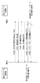
図20は、マスター機器であるデジタルカメラ100(機器A)がスレーブ機器であるプリンタ101(機器B)に対して機器能力を収集するシーケンスを示す図である。以下詳細に説明する。 FIG. 20 is a diagram illustrating a sequence in which the digital camera 100 (device A) as a master device collects device capabilities for the printer 101 (device B) as a slave device. This will be described in detail below.
まず、マスター機器であるデジタルカメラ100が機器能力収集要求をプリンタ101に対して行う(F2001)。スレーブ機器であるプリンタ101はこの要求に応答する形で機器能力収集応答を要求元のデジタルカメラ100へ自機器が有する機器能力属性値データを含む形で返信する(F2002)。この場合、マスター機器では、機器能力収集ステップタイマTCM100を起動し、その間に現在存在しているはずのスレーブ機器に対して上述した機器能力収集を行う。
First, the
図24は、自動通信パラメータ設定に対応したマスター機器が機器能力収集ステップで行う判断処理なども含むフローチャートである。以下詳細に説明する。 FIG. 24 is a flowchart including a determination process performed in the device capability collection step by the master device corresponding to automatic communication parameter setting. This will be described in detail below.
マスター機器において、現在の状況がスレーブ機器の参加受付状態にあるか否かを調べる(S2401)。参加受付状態が締め切られている場合には、既にネットワークに参加している機器の機器能力属性値の収集が完了したため、次の通信パラメータ転送方向決定ステップ404へ進む(S2406)。 In the master device, it is checked whether or not the current status is the participation acceptance state of the slave device (S2401). If the participation acceptance status is closed, since the collection of device capability attribute values of devices already participating in the network is completed, the process proceeds to the next communication parameter transfer direction determination step 404 (S2406).
一方、まだ受付中であれば、新規のスレーブ機器(機器能力属性をまだ取得していないスレーブ機器)が存在するかを確認し(S2402)、存在する場合には、新規スレーブ機器へ機器能力収集要求を送信する(S2403)。そして機器能力収集応答をスレーブ機器から受信すると(S2404)、受信した機器能力属性値を記憶する(S2405)。 On the other hand, if it is still being accepted, it is checked whether there is a new slave device (slave device for which device capability attributes have not yet been acquired) (S2402). A request is transmitted (S2403). When the device capability collection response is received from the slave device (S2404), the received device capability attribute value is stored (S2405).
図37は、機器能力の属性値を記憶するメモリの構成の一例を示す図である。図37に示すように、マスター機器は自機器が保有している属性値のテーブル3701と、その他今回スレーブ機器より受信した属性値のリスト3702を記憶する。図37に示す例では、機器を識別するためのMACアドレスと複数の属性値のリスト(属性値1、属性値2、属性値3)から構成される。
FIG. 37 is a diagram illustrating an example of a configuration of a memory that stores attribute values of device capabilities. As shown in FIG. 37, the master device stores a table 3701 of attribute values held by the own device and a
ここで、記憶した機器能力属性値情報に基づいて通信パラメータの転送方向を決定する(S2406)。図37に示す例では、属性値1については自機器及びスレーブ機器共に「YES」であるが、属性値2については自機器が「YES」で、スレーブ機器が「NO」であるため、通信パラメータ情報の提供者として自機器を選択する。
Here, the transfer direction of the communication parameter is determined based on the stored device capability attribute value information (S2406). In the example shown in FIG. 37, the
このように、マスター機器は、常時スレーブ機器の検出を行いながら、それと独立した処理として、並行してスレーブ機器の機器能力属性値収集を行うことが可能になるため、参加受付状態を締め切り後にスレーブ機器の機器能力属性値を収集する場合に比べて処理に必要な時間を短縮することが可能になる。 In this way, the master device can collect the device capability attribute values of the slave device in parallel as a process independent of the detection of the slave device at all times. Compared to collecting device capability attribute values of devices, it is possible to reduce the time required for processing.
図22は、自動通信パラメータ設定に対応したスレーブ機器が機器能力収集ステップで行う処理のフローチャートである。以下詳細に説明する。 FIG. 22 is a flowchart of processing performed in the device capability collection step by the slave device corresponding to automatic communication parameter setting. This will be described in detail below.
自機器がスレーブ機器の場合には、マスター機器からの機器能収集要求を受信した後(S2201)、マスター機器へ自機器の機器能力を示す情報を含む機器能力収集応答メッセージを送信する(S2202)。 When the own device is a slave device, after receiving a device capability collection request from the master device (S2201), a device capability collection response message including information indicating the device capability of the own device is transmitted to the master device (S2202). .
図36は、自動通信パラメータ設定に対応した機器が機器能力収集ステップで送受信するメッセージフォーマットを示す図である。まず、マスター機器では宛先MACアドレス3601に機器能力収集要求送信先のスレーブ機器のMACアドレスを挿入する。また、マスター機器である自機器のMACアドレスを送信元MACアドレス3602に挿入し、自機器が有する属性値のリストを含むメッセージを生成する。そして、そのメッセージを属性リスト3603に挿入する。
FIG. 36 is a diagram showing a message format transmitted / received by the device corresponding to automatic communication parameter setting in the device capability collection step. First, the master device inserts the MAC address of the slave device that is the device capability collection request transmission destination into the
次に、スレーブ機器ではマスター機器からの機器能力収集要求コマンド受信の応答レスポンスとして、宛先MACアドレス3601にマスター機器のMACアドレスを挿入する。また、送信元MACアドレス3602には自スレーブ機器のMACアドレスを挿入し、マスター機器と同様に、自スレーブ機器が有する機器能力属性値を属性値リスト3603に挿入し、マスター機器へ本メッセージを応答として返送する。
Next, the slave device inserts the MAC address of the master device into the
このように、マスター機器の要求メッセージとスレーブ機器からの応答メッセージとに各機器の機器能力属性値を含めることで、両者で互いの機器能力を把握することが可能になる。また、これによってスレーブ機器もマスター機器からの機器能力収集要求メッセージに含まれる属性値と自機器が有する機器能力属性値に一致が見られないと判断した場合には、機器能力属性値の応答を返さずに、即座に自動通信パラメータ設定の停止を行うことが可能になり、ユーザにすばやく自動通信パラメータ設定の処理結果を通知することができる。 Thus, by including the device capability attribute value of each device in the request message of the master device and the response message from the slave device, it becomes possible to grasp the device capabilities of each other. In addition, if the slave device determines that the attribute value included in the device capability collection request message from the master device does not match the device capability attribute value of the own device, the slave device returns a response of the device capability attribute value. Without returning, it is possible to immediately stop the automatic communication parameter setting, and promptly notify the processing result of the automatic communication parameter setting to the user.
次に、マスター機器がスレーブ機器の機器能力属性値を収集し、通信パラメータの転送方向を決定する処理について説明する。ここでは、図32及び図37を参照しながら詳細に説明する。 Next, a process in which the master device collects the device capability attribute values of the slave devices and determines the transfer direction of the communication parameters will be described. Here, it demonstrates in detail, referring FIG.32 and FIG.37.
図32は、通信パラメータの転送方向決定処理を示すフローチャートである。まず、マスター機器であるデジタルカメラ100がスレーブ機器であるプリンタ101の機器能力属性値を収集し(S3201)、機器能力属性値テーブルを図37に示す形式3702でRAM204に記憶する(S3202)。そして、全てのスレーブ機器の機器能力属性値テーブルの全属性値が確認完了済みか否かを調べ(S3203)、完了していなければ、マスター機器、スレーブ機器の機器能力属性値が記憶されている機器能力属性値テーブルの現属性値が「YES」の機器を抽出する(篩いにかけて残す)(S3204)。次に、抽出した機器が一台か否か(篩いにかけて残った機器の台数)を調べる(S3205)。
FIG. 32 is a flowchart showing communication parameter transfer direction determination processing. First, the
ここで、抽出した機器が一台でなければ、現在比較中の属性値を次の比較対象となる属性値に進め(S3206)、上述の処理を繰り返す(S3203)。また全属性値の確認が完了し、抽出した機器が一台だけの場合には(S3207)、抽出した機器をパラメータ提供者に設定する(S3208)。また、抽出した機器が複数台存在した場合には転送方向決定がエラーとなった旨を通知する(S3209)。 If the number of extracted devices is not one, the attribute value currently being compared is advanced to the attribute value to be compared next (S3206), and the above processing is repeated (S3203). If all the attribute values have been confirmed and there is only one extracted device (S3207), the extracted device is set as the parameter provider (S3208). If there are a plurality of extracted devices, it is notified that the transfer direction determination has become an error (S3209).
このように、複数の属性値から構成される属性値リストを比較してパラメータ提供者を一台の機器になるよう構成することが可能となる。また、マスター機器、スレーブ機器を含めた属性比較を行うことにより、通信用パラメータ設定用ネットワークを構成する全ての機器からマスター機器であるか、スレーブ機器であるか関係なく、通信パラメータ提供者を決めることができる。 In this way, it is possible to configure the parameter provider to be a single device by comparing attribute value lists composed of a plurality of attribute values. Also, by comparing the attributes including the master device and slave device, the communication parameter provider is determined regardless of whether the device is a master device or a slave device from all devices constituting the communication parameter setting network. be able to.
ここで、通信パラメータ転送方向決定ステップ404において通信パラメータ提供者と受理者との間で行われる通信パラメータの交換シーケンスについて説明する。
Here, a communication parameter exchange sequence performed between the communication parameter provider and the receiver in the communication parameter transfer
まず、図26を用いて、マスター機器であるデジタルカメラ100(機器A)が通信パラメータの提供者となり、スレーブ機器であるプリンタ101(機器B)が受理者となった場合に、デジタルカメラ100からプリンタ101へ通信パラメータが転送される旨を通知するシーケンスについて説明する。
First, referring to FIG. 26, when the digital camera 100 (device A) as a master device is a communication parameter provider and the printer 101 (device B) as a slave device is a receiver, the digital camera 100 A sequence for notifying that the communication parameter is transferred to the
図26は、マスター機器が通信パラメータ提供者で、受理者のスレーブ機器へ通信パラメータを提供する際のシーケンスを示す図である。まずデジタルカメラ100が「パラメータ転送方向受理者要求」メッセージをプリンタ101に送信する(F2601)。通信パラメータ受理者となったプリンタ101はその応答「パラメータ転送方向受理者応答」をデジタルカメラ100へ返信する(F2602)。その後、通信パラメータ交換処理をデジタルカメラ100からプリンタ101に対して行い(詳細は後述する)、処理が完了すれば、デジタルカメラ100は終了を表すメッセージ「パラメータ転送方向受理者完了要求」をプリンタ101へ送信する(F2603)。そして、プリンタ101はその応答「パラメータ転送方向受理者完了応答」メッセージをデジタルカメラ100へ返信する(F2604)。
FIG. 26 is a diagram showing a sequence when the master device is a communication parameter provider and provides communication parameters to the slave device of the receiver. First, the
また、この時、図31に示すように、デジタルカメラ100は通信パラメータ受理者となったプリンタ101に対して通信パラメータ提供者となった自機器のMACアドレスを通知する。そして、プリンタ101がそのアドレスを受信後、通信パラメータ提供者から送信される通信パラメータをRAM304などに保存する。
At this time, as shown in FIG. 31, the
次に、図27を用いて、マスター機器であるデジタルカメラ100(機器A)が通信パラメータの受理者となり、スレーブ機器であるプリンタ101(機器B)が提供者となった場合に、プリンタ101からデジタルカメラ100へ通信パラメータを転送するように通知するシーケンスについて説明する。
Next, referring to FIG. 27, when the digital camera 100 (device A) as a master device becomes a communication parameter receiver and the printer 101 (device B) as a slave device becomes a provider, the printer 101 A sequence for notifying the
図27は、マスター機器が通信パラメータ受理者で、通信パラメータ提供者のスレーブ機器から通信パラメータを受理する際のシーケンスを示す図である。まずデジタルカメラ100が「パラメータ転送方向提供者要求」メッセージをプリンタ101に送信する(F2701)。通信パラメータ提供者となったプリンタ101はその応答「パラメータ転送方向提供者応答」をデジタルカメラ100へ返信する(F2702)。その後、通信パラメータ交換処理をプリンタ101からデジタルカメラ100に対して行い(詳細は後述する)、処理が完了すれば、プリンタ101は終了を表すメッセージ「パラメータ転送方向提供者完了要求」をデジタルカメラ100へ送信する(F2703)。そして、デジタルカメラ100はその応答「パラメータ転送方向提供者完了応答」メッセージをプリンタ101へ返信する(F2704)。
FIG. 27 is a diagram illustrating a sequence when a master device is a communication parameter acceptor and accepts communication parameters from a slave device of a communication parameter provider. First, the
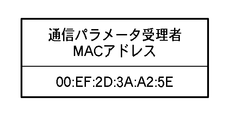
また、この時、図38に示すように、デジタルカメラ100は通信パラメータ提供者となったプリンタ101に対して通信パラメータ受理者となった自機器のMACアドレスを通知する。そして、プリンタ101がそのアドレスを受信後、通信パラメータ受理者となったデジタルカメラ100へ通信パラメータを送信する。そして、デジタルカメラ100はプリンタ101から送信される通信パラメータをRAM204に保存する。
At this time, as shown in FIG. 38, the
このように、マスター機器とスレーブ機器の関係とは別に通信パラメータ受理者と通信パラメータ提供者を決定することが可能となり、ネットワーク管理を行う処理と通信パラメータ転送を独立した機能として動作させることが可能になる。 In this way, it is possible to determine the communication parameter receiver and the communication parameter provider separately from the relationship between the master device and the slave device, and the network management process and communication parameter transfer can be operated as independent functions. become.
次に、図29を用いて、マスター機器において自動通信パラメータ設定に対応した機器が通信パラメータ提供者か通信パラメータ受理者かを決定する転送方向決定処理について説明する。 Next, transfer direction determination processing for determining whether a device corresponding to automatic communication parameter setting in the master device is a communication parameter provider or a communication parameter receiver will be described with reference to FIG.
図29は、マスター機器転送方向決定処理を示すフローチャートである。まずマスター機器である機器Aは、同一ネットワーク上に存在するスレーブ機器の台数を確認する(S2901)。次に、全スレーブ機器との処理が完了したか否かをチェックする(S2902)。もし未完了であれば、スレーブ機器アドレスリストに含まれるスレーブ機器の中でパラメータ転送方向を未だ通知していないスレーブ機器を選択する(S2903)。そして、マスター機器自身が通信パラメータ提供者となったか否かをチェックする(S2904)。マスター機器自身が通信パラメータ提供者となった場合は、ステップS2903で選択したスレーブ機器に送信する転送方向要求メッセージに、図31に示すように、パラメータ提供者となった自身のMACアドレスを設定し(S2905)、選択したスレーブ機器へパラメータ転送方向受理者要求を示すメッセージを送信する(S2906)。 FIG. 29 is a flowchart showing master device transfer direction determination processing. First, the device A as the master device checks the number of slave devices existing on the same network (S2901). Next, it is checked whether or not the processing with all slave devices has been completed (S2902). If not completed, a slave device not yet notified of the parameter transfer direction is selected from the slave devices included in the slave device address list (S2903). Then, it is checked whether or not the master device itself is a communication parameter provider (S2904). When the master device itself becomes the communication parameter provider, as shown in FIG. 31, in the transfer direction request message transmitted to the slave device selected in step S2903, the own MAC address that becomes the parameter provider is set. (S2905), a message indicating a parameter transfer direction receiver request is transmitted to the selected slave device (S2906).
次に、選択したスレーブ機器からのパラメータ転送方向受理者応答メッセージの受信を待つ(S2907)。その後、受信すると、選択したスレーブ機器を転送方向通知完了に設定し(S2908)、ステップS2902に戻り、全スレーブ機器との処理が完了するまで上述の処理を繰り返す。 Next, it waits for reception of a parameter transfer direction receiver response message from the selected slave device (S2907). Thereafter, upon reception, the selected slave device is set to transfer direction notification completion (S2908), the process returns to step S2902, and the above-described processing is repeated until the processing with all slave devices is completed.
また、マスター機器は自身が通信パラメータ受理者の場合には(S2904)、選択したスレーブ機器が通信パラメータ提供者か否かをチェックする(S2909)。ここで、通信パラメータの提供者である場合には、選択したスレーブ機器に送信する転送方向要求メッセージには、図38に示すようにパラメータ受理者となった自身のMACアドレスに加えて他にスレーブ機器が存在していればそれらの機器のMACアドレスを設定し(S2910)、選択したスレーブ機器へパラメータ転送方向提供者要求を示すメッセージを送信する(S2911)。 If the master device is a communication parameter receiver (S2904), the master device checks whether the selected slave device is a communication parameter provider (S2909). Here, in the case of a communication parameter provider, in the transfer direction request message transmitted to the selected slave device, in addition to the own MAC address that has become the parameter receiver as shown in FIG. If devices exist, the MAC addresses of these devices are set (S2910), and a message indicating a parameter transfer direction provider request is transmitted to the selected slave device (S2911).
次に、選択したスレーブ機器からのパラメータ転送方向提供者応答メッセージの受信を待つ(S2907)。その後、受信すると、選択したスレーブ機器を転送方向通知完了に設定し(S2908)、ステップS2902に戻り、全スレーブ機器との処理が完了するまで上述の処理を繰り返す。 Next, it waits for reception of a parameter transfer direction provider response message from the selected slave device (S2907). Thereafter, upon reception, the selected slave device is set to transfer direction notification completion (S2908), the process returns to step S2902, and the above-described processing is repeated until the processing with all slave devices is completed.
更に、マスター機器自身が通信パラメータの受理者、かつ選択スレーブ機器が通信パラメータ受理者の場合には(S2904,S2909)、選択したスレーブ機器に送信する転送方向要求メッセージにはパラメータ提供者となったスレーブ機器のMACアドレスを設定する(S2912)。そして、選択したスレーブ機器へパラメータ転送方向受理者要求を示すメッセージを送信する(S2913)。 Further, when the master device itself is a communication parameter acceptor and the selected slave device is a communication parameter acceptor (S2904, S2909), it becomes a parameter provider in the transfer direction request message transmitted to the selected slave device. The MAC address of the slave device is set (S2912). Then, a message indicating a parameter transfer direction receiver request is transmitted to the selected slave device (S2913).
次に、選択したスレーブ機器からのパラメータ転送方向受理者応答メッセージの受信を待つ(S2907)。その後、受信すると、選択したスレーブ機器を転送方向完了に設定し(S2908)、ステップS2902に戻り、全スレーブ機器との処理が完了するまで上述の処理を繰り返す。 Next, it waits for reception of a parameter transfer direction receiver response message from the selected slave device (S2907). Thereafter, upon reception, the selected slave device is set to transfer direction completion (S2908), the process returns to step S2902, and the above-described processing is repeated until the processing with all slave devices is completed.
次に、図30を用いて、スレーブ機器において自動通信パラメータ設定に対応した機器が通信パラメータ提供者か通信パラメータ受理者かを決定する転送方向決定処理について説明する。 Next, transfer direction determination processing for determining whether a device corresponding to automatic communication parameter setting in a slave device is a communication parameter provider or a communication parameter receiver will be described with reference to FIG.
図30は、スレーブ機器転送方向決定処理を示すフローチャートである。まずマスター機器からの通信パラメータ転送方向要求メッセージの受信チェックを行い(S3001)、受信するとマスター機器へ通信パラメータ転送方向応答メッセージを送信する(S3002)。ここで、マスター機器からの転送方向要求の役割が通信パラメータ提供者であれば(S3003のYES)、通信パラメータ転送方向要求メッセージに含まれる通信パラメータ受理者のMACアドレスリストを記憶する(S3004)。また、マスター機器からの転送方向要求の役割が通信パラメータ受理者であれば(S3003のNO)、通信パラメータ転送方向要求に含まれる通信パラメータ提供者のMACアドレスを記憶する(S3005)。 FIG. 30 is a flowchart showing slave device transfer direction determination processing. First, a reception check of a communication parameter transfer direction request message from the master device is performed (S3001), and when received, a communication parameter transfer direction response message is transmitted to the master device (S3002). If the role of the transfer direction request from the master device is the communication parameter provider (YES in S3003), the MAC address list of the communication parameter acceptor included in the communication parameter transfer direction request message is stored (S3004). If the role of the transfer direction request from the master device is a communication parameter acceptor (NO in S3003), the MAC address of the communication parameter provider included in the communication parameter transfer direction request is stored (S3005).
このように、マスター機器とスレーブ機器との間で提供者及び受理者を指示する処理を行い、事前にパラメータ転送方向をユーザに指示させることなく、各機器が通信パラメータをやりとりすべき相手機器を明らかにできる。 In this way, the process of instructing the provider and the receiver is performed between the master device and the slave device, and the partner device to which each device should exchange communication parameters without instructing the user of the parameter transfer direction in advance. Obviously.
図33は、通信パラメータの提供者と受理者との間で通信パラメータのデータを送受信する場合のシーケンスを示す図である。尚、ここでは、デジタルカメラ100が通信パラメータの提供者となり、プリンタ101が受理者となった場合を例に説明する。
FIG. 33 is a diagram illustrating a sequence in the case where communication parameter data is transmitted and received between a communication parameter provider and a receiver. Here, a case where the
通信パラメータの提供者となったデジタルカメラ100は、通信パラメータのデータの送受信に先立ちプリンタ101に対して暗証番号の入力を要求する(F3301)。これに対して、プリンタ101は暗証番号の要求に応答する形で暗証番号の値を含むデータを応答する(F3302)。次に、暗号鍵設定要求メッセージをデジタルカメラ100からプリンタ101へ送信する(F3303)。これを受けたプリンタ101は暗号鍵設定応答をデジタルカメラ100へ返信する(F3304)。
The
次に、データ要求処理に移行し、デジタルカメラ100はプリンタ101に対して通信パラメータデータを送信するが、デジタルカメラ100は通信パラメータのデータを先の暗号鍵で暗号化し、もし通信パラメータのデータが十分に大きなサイズの場合は分割する必要があるため、データ継続を示す継続(Continue)信号を付加して送信する(F3305)。それに応じてプリンタ101はデータ応答処理で継続信号の場合は更なる要求を、OKの場合はデータ送信の終了の意味を表すものとして応答信号をデジタルカメラ100へ返信する(F3306)。
Next, the process proceeds to data request processing, and the
その後、プリンタ101は受信し終わった通信パラメータデータを先の暗号鍵で復号化し、復号化した通信パラメータデータを保存する。
Thereafter, the
このように、通信の暗号化以外に第1の実施形態の中で最もセキュリティ上問題となる通信パラメータ部分を個別に暗号化することによって、より安全なセキュリティを施した通信パラメータ転送を行うことができる。 In this way, communication parameter transfer with more secure security can be performed by individually encrypting the communication parameter part that causes the most security problem in the first embodiment in addition to communication encryption. it can.
ここで、通信パラメータの提供者(この例ではデジタルカメラ100)と受理者(この例ではプリンタ101)とで通信パラメータのデータを授受する場合に、通信パラメータの提供者となった機器(この例ではデジタルカメラ100)で執り行われる処理について詳細に説明する。 Here, when communication parameter data is exchanged between a communication parameter provider (in this example, the digital camera 100) and a receiver (in this example, the printer 101), the device (in this example) that is the communication parameter provider Now, the processing performed by the digital camera 100) will be described in detail.
図34は、通信パラメータを提供する機器での処理を示すフローチャートである。まず、通信パラメータの提供者であるデジタルカメラ100は、通信パラメータ情報を転送しなければならない通信パラメータ受理者の台数をデジタルカメラ100のRAM204に設定記憶する(S3401)。次に、全ての通信パラメータ受理者となる機器に対して通信パラメータの送信が完了したか否かを調べ(S3402)、完了していれば正常終了とし、また完了していなければ以下の処理を繰り返し実行する。
FIG. 34 is a flowchart showing processing in a device that provides communication parameters. First, the
まず、通信パラメータを未送信のパラメータ受理者機器のアドレスを送信先のアドレスとして設定する(S3403)。次に、設定した送信先のアドレスを表すパラメータ受理者機器に暗証番号要求メッセージを送信する(S3404)。そして、パラメータ受理者機器から暗証番号応答メッセージを受信するまで待ち(S3405)、受信すると、暗証番号応答メッセージに含まれる応答暗証番号が正しいか否かを調べる(S3406)。 First, the address of the parameter receiver device that has not yet transmitted the communication parameter is set as the address of the transmission destination (S3403). Next, the personal identification number request message is transmitted to the parameter receiver device indicating the set destination address (S3404). Then, it waits until a password response message is received from the parameter receiver device (S3405). Upon reception, it is checked whether or not the response password included in the password response message is correct (S3406).
ここで、応答暗証番号が正しければ、引き続いてパラメータ受理者機器に暗号鍵の要求メッセージを送信し(S3407)、パラメータ受理者機器から暗号鍵応答メッセージの受信を待つ(S3408)。受信すると、暗号鍵応答メッセージとして送られてきた暗号鍵を用いて今から送信したい通信パラメータ情報を暗号鍵で暗号化し(S3409)、暗号化通信パラメータ情報をパラメータ受理者機器へ送信する(S3410)。そして、受理者機器から通信パラメータ情報応答メッセージの受信を待ち(S3411)、受信すると、次のパラメータ受理者機器を選択する処理へ移行する(S3412)。 If the response code number is correct, an encryption key request message is subsequently transmitted to the parameter receiver device (S3407), and the reception of the encryption key response message from the parameter receiver device is awaited (S3408). When received, the communication parameter information to be transmitted from now on is encrypted with the encryption key using the encryption key sent as the encryption key response message (S3409), and the encrypted communication parameter information is transmitted to the parameter receiver device (S3410). . Then, it waits for reception of a communication parameter information response message from the acceptor device (S3411), and when received, the process proceeds to processing for selecting the next parameter acceptor device (S3412).
また、パラメータ受理者機器から受信した暗証番号応答メッセージに含まれる暗証番号が正しくないと判断した場合は(S3406のNO)、暗証番号再要求をパラメータ受理者機器に送信する(S3413)。もしその応答として暗証番号要求の拒否メッセージを受信した場合は(S3414のYES)、エラー終了となる。また、暗証番号要求の拒否メッセージではなく、暗証番号応答メッセージを受信した場合は(S3405のYES)、上述した処理を繰り返し行う。 If it is determined that the security code included in the security code response message received from the parameter receiver device is not correct (NO in S3406), a password re-request is transmitted to the parameter receiver device (S3413). If a password rejection message is received as a response (YES in S3414), the process ends in an error. Further, when a password response message is received instead of a password request rejection message (YES in S3405), the above-described processing is repeated.
次に、通信パラメータの提供者(この例ではデジタルカメラ100)と受理者(この例ではプリンタ101)とで通信パラメータのデータを授受する場合に、通信パラメータの受理者となった機器(この例ではプリンタ101)で執り行われる処理について詳細に説明する。 Next, when communication parameter data is exchanged between the communication parameter provider (in this example, the digital camera 100) and the receiver (in this example, the printer 101), the device that has received the communication parameter (in this example) Now, the processing performed by the printer 101) will be described in detail.
図35は、通信パラメータを受理する機器での処理を示すフローチャートである。まず、通信パラメータの受理者であるプリンタ101は、通信パラメータの提供者であるデジタルカメラ100から暗証番号要求メッセージの受信を待つ(S3501)。要求を受信した場合、操作部310に暗証番号の入力をユーザに促す表示を行い、ユーザにより入力された暗証番号を通信パラメータ提供者機器へ暗証番号応答メッセージとして送信する(S3502)。そして、通信パラメータの提供者機器から暗証番号再要求メッセージを受信した場合は(S3503のYES)、暗証番号を誤って入力した場合などが考えられるので、処理を中止するか否かをプリンタ101の表示部310に表示し、操作の中止を表すキャンセルなどが操作部312より入力されれば(S3504のYES)、プリンタ101はデジタルカメラ100へ暗証番号要求拒否メッセージを送信し、エラー終了となる(S3505)。
FIG. 35 is a flowchart showing processing in a device that accepts communication parameters. First, the
また、暗証番号が正しく入力されていれば、続けて通信パラメータ提供者機器から暗号鍵要求が送信されるのでこれを受信するまで待ち(S3506)、通信パラメータ提供者であるデジタルカメラ100に対して暗号鍵を応答として送信する(S3507)。その後、通信パラメータ提供者機器から通信パラメータ要求メッセージを受信するまで待ち(S3508)、受信すると、通信パラメータ提供者機器に通信パラメータ情報応答メッセージを送信し(S3509)、通信パラメータ要求メッセージを先の暗号鍵にて復号化し(S3510)、通信パラメータを取得し、保存して(S3511)正常終了となる。
If the code number is correctly input, an encryption key request is continuously transmitted from the communication parameter provider device, so that the request is received (S3506), and the
各機器は、ステップS3511で通信パラメータ情報を記憶すると、該通信パラメータを新規ネットワークの通信パラメータとして設定することにより、通信パラメータ設定用ネットワークから抜け出し、新規ネットワークを形成する。 When each device stores the communication parameter information in step S3511, it sets the communication parameter as a communication parameter for the new network, thereby exiting the communication parameter setting network and forming a new network.
[第2の実施形態]
次に、図面を参照しながら本発明に係る第2の実施形態について詳細に説明する。第1の実施形態では、2台の機器間における自動通信パラメータ設定について説明したが、第2の実施形態では複数の機器間における自動通信パラメータ設定の特徴的な部分について説明する。
[Second Embodiment]
Next, a second embodiment according to the present invention will be described in detail with reference to the drawings. In the first embodiment, automatic communication parameter setting between two devices has been described. In the second embodiment, characteristic parts of automatic communication parameter setting between a plurality of devices will be described.
図40は、第2の実施形態における無線LANの構成の一例を示す図である。図40に示すように、無線通信機器A、B、Cは、デジタルカメラ100(機器A)、プリンタ101(機器B)、デジタルカメラ106(機器C)であり、3者間でアドホック通信の無線通信パラメータ設定を行う。 FIG. 40 is a diagram illustrating an example of a configuration of a wireless LAN according to the second embodiment. As shown in FIG. 40, wireless communication devices A, B, and C are a digital camera 100 (device A), a printer 101 (device B), and a digital camera 106 (device C), and wireless communication for ad hoc communication between the three parties. Set communication parameters.
デジタルカメラ100は無線通信機能104として無線LANを有し、通信パラメータ設定起動ボタン102を押下することにより通信パラメータ設定モードのネットワークを構成することが可能である。またプリンタ101も無線通信機能105として無線LANを有し、通信パラメータ設定起動ボタン103を押下することにより通信パラメータ設定モードのネットワークを構成することが可能である。更にデジタルカメラ106も無線通信機能108として無線LANを有し、通信パラメータ設定起動ボタン107を押下することにより通信パラメータ設定モードのネットワークを構成することが可能である。
The
尚、デジタルカメラ100(機器A)及びデジタルカメラ106(機器C)、プリンタ101(機器B)の構成は、第1の実施形態で図2、図3を用いて説明した構成と同様であり、ここでの説明は省略する。 The configurations of the digital camera 100 (device A), the digital camera 106 (device C), and the printer 101 (device B) are the same as those described with reference to FIGS. 2 and 3 in the first embodiment. The description here is omitted.
次に、第1の実施形態と同様に、アドホックネットワークにおいてマスター機器が存在しない場合に、図2に示す機器Aと機器Bと機器Cとの間でマスター機器とスレーブ機器を決定する処理について、図21を用いて説明する。 Next, as in the first embodiment, when there is no master device in the ad hoc network, a process for determining a master device and a slave device between the devices A, B, and C shown in FIG. This will be described with reference to FIG.
図21は、第2の実施形態におけるマスター機器とスレーブ機器とを決定するシーケンスを示す図である。尚、図21に示す例では、機器Aが処理を開始した後に機器Bが処理を開始し、更に機器Cが処理を開始する場合を例に説明する。また、この例では、機器C、機器A、機器Bの順にMACアドレスの辞書式順序が小さいものとする。 FIG. 21 is a diagram illustrating a sequence for determining a master device and a slave device according to the second embodiment. In the example illustrated in FIG. 21, a case where the device B starts processing after the device A starts processing, and the device C starts processing will be described as an example. In this example, it is assumed that the lexicographic order of the MAC addresses is smaller in the order of device C, device A, and device B.
機器Aが処理を開始した後、マスター問合せ起動時間(TH2100)の間、ランダムタイマを起動してメッセージの送信を待機する。 After the device A starts processing, the random timer is activated during the master inquiry activation time (TH2100) to wait for message transmission.
その後、ランダムタイマがタイムアップすると、機器Aはマスター問合せ送信タイマにマスター問合せ送信間隔(TH2101)を設定して起動し、マスター問合せ送信タイマのタイムアップ毎にマスター問合せメッセージを送信する。この例の場合、マスター問合せメッセージの送信を3回行う(F2102、F2103、F2104)。 Thereafter, when the random timer expires, the device A starts by setting the master inquiry transmission interval (TH2101) in the master inquiry transmission timer, and transmits a master inquiry message every time the master inquiry transmission timer expires. In this example, the master inquiry message is transmitted three times (F2102, F2103, F2104).
機器Bが処理を開始した後、マスター問合せ起動時間(TH2105)の間、ランダムタイマを起動してメッセージの送信を待機する。 After the device B starts processing, the random timer is activated during the master inquiry activation time (TH2105) to wait for message transmission.
その後、ランダムタイマがタイムアップすると、機器Bはマスター問合せ送信タイマにマスター問合せ送信間隔(TH2106)を設定して起動し、マスター問合せ送信タイマのタイムアップ毎にマスター問合せメッセージを3回送信する(F2107、F2108、F2109)。 Thereafter, when the random timer expires, the device B starts by setting a master inquiry transmission interval (TH2106) in the master inquiry transmission timer, and transmits a master inquiry message three times every time the master inquiry transmission timer expires (F2107). F2108, F2109).
機器Cが処理を開始した後、マスター問合せ起動時間(TH2110)の間、ランダムタイマを起動してメッセージの送信を待機する。 After the device C starts processing, the random timer is activated during the master inquiry activation time (TH2110) to wait for message transmission.
その後、ランダムタイマがタイムアップすると、機器Cはマスター問合せ送信タイマにマスター問合せ送信間隔(TH2111)を設定して起動し、マスター問合せ送信タイマのタイムアップ毎にマスター問合せメッセージを3回送信する(F2112、F2113、F2114)。 Thereafter, when the random timer expires, the device C starts by setting the master inquiry transmission interval (TH2111) in the master inquiry transmission timer, and transmits the master inquiry message three times every time the master inquiry transmission timer expires (F2112). , F2113, F2114).
次に、機器Aがマスター問合せメッセージを送信後、マスター宣言受信タイマを起動し、マスター問合せ応答待ち時間(TH2115)の間にメッセージが送信されるのを待つ。この例の場合、機器Aは所定時間(TH2115)の間に機器B、機器Cよりマスター問合せメッセージを受信するため、マスター衝突解決処理を二回行う。 Next, after the device A transmits a master inquiry message, it starts a master declaration reception timer and waits for a message to be transmitted during the master inquiry response waiting time (TH2115). In this example, since the device A receives the master inquiry message from the devices B and C during the predetermined time (TH2115), the master collision solution processing is performed twice.
第2の実施形態でも第1の実施形態と同様に、機器Aがマスター衝突解決処理において機器Bに対してはWinner、機器Cに対してはLoserと判定されるため、機器Aはマスター宣言受信タイマのタイムアップ後、マスター宣言受信待ちタイマを起動し、所定時間(TH2118)の間にマスター宣言メッセージが送信されるのを待つ(図8に示すS820の処理に相当)。 In the second embodiment, as in the first embodiment, since device A is determined to be winner for device B and Loser for device C in the master collision resolution process, device A receives the master declaration. After the timer expires, a master declaration reception waiting timer is started and waits for a master declaration message to be transmitted during a predetermined time (TH2118) (corresponding to the process of S820 shown in FIG. 8).
ここで、機器Bはマスター問合せメッセージを送信後、マスター宣言受信タイマを起動し、マスター問合せ応答待ち時間(TH2116)の間にメッセージが送信されるのを待つ。この例の場合、機器Bは所定時間(TH2116)の間に機器Cよりマスター問合せメッセージを受信するため、マスター衝突解決処理を行う。 Here, after transmitting the master inquiry message, the device B activates a master declaration reception timer and waits for a message to be transmitted during the master inquiry response waiting time (TH2116). In the case of this example, the device B receives the master inquiry message from the device C during the predetermined time (TH2116), and therefore performs the master collision resolution process.
第2の実施形態でも第1の実施形態と同様にマスター衝突解決処理を行い、機器Bがマスター衝突解決処理において機器Cに対してはLoserと判定されたとする。機器Bはマスター宣言受信タイマのタイムアップ後、マスター宣言受信待ちタイマを起動し、所定時間(TH2119)の間にマスター宣言メッセージが送信されるのを待つ。 In the second embodiment, it is assumed that the master collision resolution process is performed similarly to the first embodiment, and the device B is determined to be Loser for the device C in the master collision resolution process. After the master declaration reception timer expires, the device B activates a master declaration reception waiting timer and waits for a master declaration message to be transmitted during a predetermined time (TH2119).
また、機器Cはマスター問合せメッセージを送信後、マスター宣言受信タイマを起動し、マスター問合せ応答待ち時間(TH2117)の間にメッセージが送信されるのを待つ。この例の場合、機器Cは所定時間(TH2117)の間にはマスター問合せメッセージを受信しないため、機器Cはマスター宣言受信タイマのタイムアップ後、マスター宣言メッセージのブロードキャスト送信を行うことで、機器Cがマスター機器であることを他の機器に通知する(F2120)。 In addition, after transmitting the master inquiry message, the device C activates a master declaration reception timer and waits for a message to be transmitted during the master inquiry response waiting time (TH2117). In this example, the device C does not receive the master inquiry message during the predetermined time (TH2117). Therefore, the device C performs broadcast transmission of the master declaration message after the master declaration reception timer expires, so that the device C Is notified to the other device (F2120).
機器Cは、マスター宣言メッセージを送信後、マスター宣言送信タイマにマスター宣言送信間隔(TH2121)を設定して起動し、マスター宣言送信タイマのタイムアップ毎に周期的にマスター宣言メッセージをブロードキャスト送信(F2122)する。 After transmitting the master declaration message, the device C sets the master declaration transmission timer with a master declaration transmission interval (TH2121) and starts up, and periodically broadcasts the master declaration message every time the master declaration transmission timer expires (F2122). )
これにより、機器Bは所定時間(TH2119)の間に機器Cよりマスター宣言メッセージを受信し、機器Cがマスター機器であることを検知する。そして、機器Bはマスター機器管理テーブルに機器CのMACアドレスを登録し、マスター機器存在タイマにマスター宣言メッセージより取得した機器Cの存在時間を設定してタイマを起動し、機器Cへスレーブ宣言メッセージを送信(F2123)する。 As a result, the device B receives the master declaration message from the device C during the predetermined time (TH2119), and detects that the device C is the master device. Then, the device B registers the MAC address of the device C in the master device management table, sets the existing time of the device C acquired from the master declaration message in the master device existence timer, starts the timer, and sends a slave declaration message to the device C. Is transmitted (F2123).
機器Bは、スレーブ宣言メッセージを送信後、スレーブ宣言送信タイマにスレーブ宣言送信間隔(TH2124)を設定して起動し、スレーブ宣言送信タイマのタイムアップ毎に周期的にスレーブ宣言メッセージを機器Cへ送信(F2125)する。 After transmitting the slave declaration message, device B sets the slave declaration transmission interval (TH2124) in the slave declaration transmission timer and starts it, and periodically transmits the slave declaration message to device C every time the slave declaration transmission timer expires. (F2125).
一方、機器Aは所定時間(TH2118)の間に機器Cよりマスター宣言メッセージを受信し、機器Cがマスター機器であることを検知する。そして、機器Aはマスター機器管理テーブルに機器CのMACアドレスを登録し、マスター機器存在タイマにマスター宣言メッセージより取得した機器Cの存在時間を設定してタイマを起動し、機器Cへスレーブ宣言メッセージを送信(F2126)する。 On the other hand, the device A receives a master declaration message from the device C during a predetermined time (TH2118), and detects that the device C is a master device. Then, the device A registers the MAC address of the device C in the master device management table, sets the existing time of the device C acquired from the master declaration message in the master device existence timer, starts the timer, and sends a slave declaration message to the device C. Is transmitted (F2126).
機器Aは、スレーブ宣言メッセージを送信後、スレーブ宣言送信タイマにスレーブ宣言送信間隔(TH2127)を設定して起動し、スレーブ宣言送信タイマのタイムアップ毎に周期的にスレーブ宣言メッセージを機器Cへ送信(F2128)する。 After transmitting the slave declaration message, device A starts by setting the slave declaration transmission interval (TH2127) in the slave declaration transmission timer, and periodically transmits the slave declaration message to device C every time the slave declaration transmission timer expires. (F2128).
以上の手順をもって、図21に示す第2の実施形態において、マスター機器とスレーブ機器が決定される。 With the above procedure, the master device and the slave device are determined in the second embodiment shown in FIG.
次に、第1の実施形態と同様に、マスター機器決定ステップ402で決定したマスター機器が同一ネットワークに参加しているスレーブ機器から機器能力を収集する第2の実施形態における機器能力収集ステップ403について説明する。
Next, as in the first embodiment, the device
図23は、マスター機器としてのデジタルカメラ106(機器C)がスレーブ機器としてのプリンタ101(機器B)及びデジタルカメラ100(機器A)から機器能力を収集するシーケンスを示す図である。以下詳細に説明する。 FIG. 23 is a diagram illustrating a sequence in which the digital camera 106 (device C) as a master device collects device capabilities from the printer 101 (device B) and the digital camera 100 (device A) as slave devices. This will be described in detail below.
まず、デジタルカメラ106(機器C)は、マスター機器として現在同一ネットワーク上に存在するスレーブ機器の機器能力属性値データを収集するために、プリンタ101(機器B)に対して機器能力収集要求を送信する(F2301)。これを受信したプリンタ101は自身の機器能力属性値を含む機器能力収集応答を返信する(F2302)。
First, the digital camera 106 (device C) transmits a device capability collection request to the printer 101 (device B) in order to collect device capability attribute value data of a slave device that currently exists on the same network as the master device. (F2301). Upon receiving this, the
また、デジタルカメラ106はスレーブ機器であるデジタルカメラ100(機器A)に対して機器能力収集要求を送信する(F2303)。これを受信したデジタルカメラ100は自身の機器能力属性値を含む機器能力収集応答を返信する(F2304)。
In addition, the
このように、マスター機器であるデジタルカメラ106は現在同一ネットワーク上に存在する全てのスレーブ機器の機器能力属性値データを収集する。そして、マスター機器がネットワーク管理者として同一ネットワーク上に存在する各スレーブ機器の機器能力収集を行うことにより、3台以上の機器が同一ネットワーク上に存在し、任意のタイミングでスレーブ機器の参加が発生しても、その都度、即座にマスター機器による機器能力収集を行うことが可能になる。
As described above, the
図25は、マスター機器が同一ネットワーク上の全ての機器から機器能力属性を収集した後の機器能力属性テーブルを示す図である。以下、この機器能力属性値からどのようにして通信パラメータ情報提供者を決定するかについて説明する。 FIG. 25 is a diagram illustrating a device capability attribute table after the master device collects device capability attributes from all devices on the same network. Hereinafter, how the communication parameter information provider is determined from the device capability attribute value will be described.
尚、この決定処理は、第1の実施形態で図32を用いて説明した通信パラメータの転送方向決定処理を適用可能である。 Note that the communication parameter transfer direction determination process described with reference to FIG. 32 in the first embodiment can be applied to this determination process.
まず、属性値1についてフィルタをかける。属性値1の機能を持つ機器、即ち、属性値1が「YES」の機器は次の比較ステップの候補となる。従って、図25に示すように、機器番号が「2」の属性値1は「NO」であるため、機器番号「2」は比較対象から脱落する。
First, the
次に、属性値2について残った機器番号「1」、「3」、「4」に対して比較を行う。この場合、機器番号「1」の機器が、属性値2が「NO」であるため、機器番号「1」は以後比較対象から脱落する。
Next, the remaining device numbers “1”, “3”, and “4” for
次に、属性値3について機器番号「3」と「4」に対して比較を行う。この場合、機器番号「3」が、属性値3が「YES」のため、最終的に残り、通信パラメータ情報提供者として選択される。
Next, with respect to the
このように、複数の属性値からなる属性値リストで順次フィルタをかけて最終的な通信パラメータ情報提供者を決定することが可能となり、複数の属性値に重み付けを付けることにより、ある特定の機器能力を有するものを通信パラメータ情報提供者として選択することが可能となる。 In this way, it is possible to sequentially filter the attribute value list including a plurality of attribute values to determine the final communication parameter information provider, and by weighting the plurality of attribute values, a specific device It is possible to select a communication parameter information provider having capability.
次に、図28を用いて、デジタルカメラ100(機器A)とプリンタ101(機器B)がスレーブ機器で、デジタルカメラ106(機器C)がマスター機器の場合に、マスター機器であるデジタルカメラ106(機器C)がスレーブ機器であるデジタルカメラ100(機器A)に対して通信パラメータ受理者である旨を通知し、また、スレーブ機器であるプリンタ101(機器B)に対して通信パラメータ提供者である旨を通知し、機器Bからの通信パラメータを機器A、機器Cへ転送するシーケンスについて説明する。 Next, referring to FIG. 28, when the digital camera 100 (device A) and the printer 101 (device B) are slave devices and the digital camera 106 (device C) is a master device, the digital camera 106 (master device) The device C) notifies the digital camera 100 (device A), which is a slave device, that it is a communication parameter acceptor, and is a communication parameter provider to the printer 101 (device B), which is a slave device. A sequence for notifying that and transferring the communication parameters from the device B to the devices A and C will be described.
尚、この処理は、第1の実施形態で図29を用いて説明した処理と同様である。 This process is the same as the process described with reference to FIG. 29 in the first embodiment.
図28は、第2の実施形態における通信パラメータの転送シーケンスを示す図である。マスター機器であるデジタルカメラ106(機器C)は、先の通信パラメータの提供者を決定する処理により、スレーブ機器であるデジタルカメラ100を通信パラメータの受理者、スレーブ機器であるプリンタ101を通信パラメータの提供者、そして、自身を通信パラメータの受理者と決定したとする。
FIG. 28 is a diagram illustrating a communication parameter transfer sequence according to the second embodiment. The digital camera 106 (device C), which is the master device, determines the provider of the previous communication parameter, and the
そこで、デジタルカメラ106(機器C)はデジタルカメラ100(機器A)に対して通信パラメータ受理者を要求する「パラメータ転送方向受理者要求」メッセージを図31に示すような通信パラメータ提供者のアドレスを含めて送信する(F2801)。デジタルカメラ100は、その応答として「パラメータ転送方向受理者応答」メッセージを返信し、通信パラメータ受理者となることを容認する(F2802)。
Therefore, the digital camera 106 (device C) sends a “parameter transfer direction receiver request” message for requesting the communication parameter receiver to the digital camera 100 (device A) with the address of the communication parameter provider as shown in FIG. It is transmitted including (F2801). The
また、デジタルカメラ106(機器C)は同様に、プリンタ101(機器B)に対して通信パラメータ提供者を要求する「パラメータ転送方向提供者要求」メッセージを図39に示すように(図39では受理者機器が6台の場合である)、全ての通信パラメータ受理者のアドレスを含めて送信する(F2803)。プリンタ101は、その応答として「パラメータ転送方向提供者応答」メッセージを返信し、通信パラメータ提供者となることを容認する(F2804)。
Similarly, the digital camera 106 (device C) similarly receives a “parameter transfer direction provider request” message for requesting a communication parameter provider from the printer 101 (device B) as shown in FIG. 39 (accepted in FIG. 39). This is a case where there are six person devices), including the addresses of all communication parameter receivers (F2803). In response, the
その後、プリンタ101(機器B)はデジタルカメラ100(機器A)と無線パラメータ交換シーケンスを行い、完了後、デジタルカメラ100はマスター機器であるデジタルカメラ106に対して通信パラメータ受理者処理の完了を表す「パラメータ転送方向受理者完了要求」メッセージを要求する(F2805)。デジタルカメラ106は、その応答として「パラメータ転送方向受理者完了応答」メッセージを返信する(F2806)。
Thereafter, the printer 101 (device B) performs a wireless parameter exchange sequence with the digital camera 100 (device A). After completion, the
また、デジタルカメラ106(機器C)とプリンタ101(機器B)も無線パラメータ交換シーケンスを行い、完了後、プリンタ101はマスター機器であるデジタルカメラ106に対して通信パラメータ提供者処理の完了を表す「パラメータ転送方向提供者完了要求」メッセージを要求する(F2807)。デジタルカメラ106は、その応答として「パラメータ転送方向提供者完了応答」メッセージを返信する(F2808)。各機器は、通信パラメータ提供者が提供した通信パラメータを新規ネットワークの通信パラメータとして設定することにより、通信パラメータ設定用ネットワークから抜け出し、新規ネットワークを形成する。
Further, the digital camera 106 (device C) and the printer 101 (device B) also perform a wireless parameter exchange sequence. After completion, the
また、第2の実施形態では明記していないが、マスター機器は自身が通信パラメータの受理者となった場合の各スレーブ機器への転送方向要求を送信する順序に関しては、まず通信パラメータの受理者となった各スレーブ機器に対して通信パラメータ受理者要求メッセージを送信する。その後、通信パラメータの提供者となったスレーブ機器に対して通信パラメータ提供者要求メッセージを送信するという順序規則を適用する。これにより、通信パラメータ交換処理で、第2の実施形態にあるような複数の機器間でも通信パラメータの提供者は、特に各通信パラメータの受理者がマスター機器から通信パラメータ受理者メッセージを既に受信したか否かを通信パラメータ提供者が調べる必要がなくなる。また、パラメータ受理者の順序を意識することもなく、即座に無線パラメータ交換シーケンスへと処理を進めることが可能となる。 Although not specified in the second embodiment, the master device first receives the communication parameter with respect to the order of transmitting the transfer direction request to each slave device when it becomes the communication parameter receiver. A communication parameter receiver request message is transmitted to each slave device. Thereafter, an ordering rule of transmitting a communication parameter provider request message to the slave device that has become the communication parameter provider is applied. As a result, in the communication parameter exchange processing, the communication parameter provider, even among a plurality of devices as in the second embodiment, has already received the communication parameter receiver message from the master device by the receiver of each communication parameter. It is not necessary for the communication parameter provider to check whether or not. In addition, it is possible to immediately proceed to the wireless parameter exchange sequence without being aware of the order of parameter receivers.
[他の実施形態]
第1及び第2の実施形態では、無線通信として、無線LANを例に挙げて説明したが、例えばBluetooth(登録商標)、WirelessUSB、Wireless1394、UWB、WiMAXなどの他の無線通信方式に本発明を適用することも可能である。
[Other Embodiments]
In the first and second embodiments, the wireless LAN has been described as an example of wireless communication. However, the present invention is applied to other wireless communication methods such as Bluetooth (registered trademark), WirelessUSB, Wireless1394, UWB, WiMAX, and the like. It is also possible to apply.
尚、本発明は複数の機器(例えば、ホストコンピュータ,インターフェース機器,リーダ,プリンタなど)から構成されるシステムに適用しても、1つの機器からなる装置(例えば、複写機,ファクシミリ装置など)に適用しても良い。 Even if the present invention is applied to a system composed of a plurality of devices (for example, a host computer, an interface device, a reader, a printer, etc.), it is applied to an apparatus (for example, a copier, a facsimile machine, etc.) composed of a single device. It may be applied.
また、本発明の目的は、前述した実施形態の機能を実現するソフトウェアのプログラムコードを記録した記録媒体を、システム或いは装置に供給し、そのシステム或いは装置のコンピュータ(CPU若しくはMPU)が記録媒体に格納されたプログラムコードを読出し実行することによっても、達成されることは言うまでもない。 Another object of the present invention is to supply a recording medium that records software program codes for realizing the functions of the above-described embodiments to a system or apparatus, and the computer (CPU or MPU) of the system or apparatus uses the recording medium as a recording medium. Needless to say, this can also be achieved by reading and executing the stored program code.
この場合、記録媒体から読出されたプログラムコード自体が前述した実施形態の機能を実現することになり、そのプログラムコードを記憶した記録媒体は本発明を構成することになる。 In this case, the program code itself read from the recording medium realizes the functions of the above-described embodiment, and the recording medium storing the program code constitutes the present invention.
このプログラムコードを供給するための記録媒体としては、例えばフロッピー(登録商標)ディスク,ハードディスク,光ディスク,光磁気ディスク,CD−ROM,CD−R,磁気テープ,不揮発性のメモリカード,ROMなどを用いることができる。 As a recording medium for supplying the program code, for example, a floppy (registered trademark) disk, a hard disk, an optical disk, a magneto-optical disk, a CD-ROM, a CD-R, a magnetic tape, a nonvolatile memory card, a ROM, or the like is used. be able to.
また、コンピュータが読出したプログラムコードを実行することにより、前述した実施形態の機能が実現されるだけでなく、そのプログラムコードの指示に基づき、コンピュータ上で稼働しているOS(オペレーティングシステム)などが実際の処理の一部又は全部を行い、その処理によって前述した実施形態の機能が実現される場合も含まれることは言うまでもない。 Further, by executing the program code read by the computer, not only the functions of the above-described embodiments are realized, but also an OS (operating system) operating on the computer based on the instruction of the program code. It goes without saying that a case where the function of the above-described embodiment is realized by performing part or all of the actual processing and the processing is included.
更に、記録媒体から読出されたプログラムコードが、コンピュータに挿入された機能拡張ボードやコンピュータに接続された機能拡張ユニットに備わるメモリに書込まれた後、そのプログラムコードの指示に基づき、その機能拡張ボードや機能拡張ユニットに備わるCPUなどが実際の処理の一部又は全部を行い、その処理によって前述した実施形態の機能が実現される場合も含まれることは言うまでもない。 Further, after the program code read from the recording medium is written into a memory provided in a function expansion board inserted into the computer or a function expansion unit connected to the computer, the function expansion is performed based on the instruction of the program code. It goes without saying that the CPU or the like provided in the board or the function expansion unit performs part or all of the actual processing and the functions of the above-described embodiments are realized by the processing.
Claims (14)
第1のアドホックネットワークを管理し、第2のアドホックネットワークで通信するために必要な暗号鍵、暗号方式を含む通信パラメータを提供する提供装置と、前記提供装置から前記通信パラメータの提供を受ける受理装置とを決定する管理装置の存在を問い合わせる問合せメッセージ、または前記管理装置の存在を通知するマスター宣言メッセージ、を送信する送信手段と、
他の通信装置が送信した、前記問合せメッセージ、または前記マスター宣言メッセージ、を受信する受信手段と、
前記送信手段及び前記受信手段により送受信されるメッセージに基づいて、前記管理装置を決定する第1の決定手段と、
前記第1の決定手段により自装置を前記管理装置と決定した場合、前記提供装置と前記受理装置とを決定するために、前記第1のアドホックネットワークに存在する他の通信装置の機器能力情報を収集する収集手段と、
前記収集手段により収集した前記他の通信装置の機器能力情報に基づいて、前記提供装置と前記受理装置とを決定する第2の決定手段と、を有し、
前記第1の決定手段は、前記管理装置が決定されておらず、前記問い合わせメッセージを受信することにより前記管理装置を探索している他の通信装置の存在を確認した場合は、該他の通信装置の情報と自装置の情報とに基づいて、前記管理装置を探索している該他の通信装置と自装置の中から前記管理装置を1台に決定するための処理を行うことを特徴とする通信装置。 A communication device that communicates via an ad hoc network in which each communication device communicates directly without being controlled by the control device ,
A providing device that manages a first ad hoc network and provides communication parameters including an encryption key and an encryption method necessary for communication on the second ad hoc network , and a receiving device that receives the communication parameters from the providing device Transmitting means for transmitting an inquiry message for inquiring about the presence of the management device or a master declaration message for notifying the presence of the management device;
Receiving means for receiving the inquiry message or the master declaration message transmitted by another communication device;
First determining means for determining the management device based on messages transmitted and received by the transmitting means and the receiving means;
When the first determination unit determines that the own device is the management device, device capability information of other communication devices existing in the first ad hoc network is used to determine the providing device and the receiving device. Collection means to collect;
Second determining means for determining the providing device and the receiving device based on the device capability information of the other communication device collected by the collecting means ;
The first determining means determines that if the management device is not determined and the presence of another communication device searching for the management device is confirmed by receiving the inquiry message, the other communication Based on the information on the device and the information on the own device, the other communication device searching for the management device and the process for determining one of the own devices from the own device are performed. Communication device.
前記第1の決定手段により他の通信装置を前記管理装置と決定した場合、該管理装置の状態を管理する第2の管理手段と、を有し、
前記送信手段は、前記第1の決定手段により前記他の通信装置を前記管理装置と決定した場合に、該他の通信装置に対して、被管理装置の存在を通知するスレーブ宣言メッセージを送信することを特徴とする請求項1に記載の通信装置。 A first management unit that manages a state of the other communication device when the first device is determined to be the management device by the first determination unit;
A second management unit that manages the state of the management device when another communication device is determined as the management device by the first determination unit;
When the first determining unit determines the other communication device as the management device, the transmission unit transmits a slave declaration message notifying the existence of the managed device to the other communication device. The communication apparatus according to claim 1.
前記スレーブ宣言メッセージは、メッセージ送信元の識別情報と、前記第1のアドホックネットワーク上に存在する存在期限情報とを含み、当該存在期限情報に基づく時間間隔で、前記管理装置へ送信されることを特徴とする請求項7に記載の通信装置。 The master declaration message includes identification information of a message transmission source and existence period information existing on the first ad hoc network, and is transmitted to the other communication device at a time interval based on the existence period information.
The slave declaration message includes identification information of a message transmission source and existence period information existing on the first ad hoc network, and is transmitted to the management apparatus at a time interval based on the existence period information. The communication apparatus according to claim 7, characterized in that:
第1のアドホックネットワークを管理し、第2のアドホックネットワークで通信するために必要な暗号鍵、暗号方式を含む通信パラメータを提供する提供装置と、前記提供装置から前記通信パラメータの提供を受ける受理装置とを決定する管理装置の存在を問い合わせる問合せメッセージ、または前記管理装置の存在を通知するマスター宣言メッセージ、を送信する送信工程と、
他の通信装置が送信した、前記問合せメッセージ、または前記マスター宣言メッセージ、を受信する受信工程と、
前記送信工程及び前記受信工程において送受信されるメッセージに基づいて、前記管理装置を決定する第1の決定工程と、
前記第1の決定工程において自装置が前記管理装置に決定された場合、前記提供装置と前記受理装置とを決定するために、前記第1のアドホックネットワークに存在する他の通信装置から機器能力情報を収集する収集工程と、
前記収集工程において収集した前記他の通信装置の機器能力情報に基づいて、前記提供装置と前記受理装置とを決定する第2の決定工程と、を有し、
前記第1の決定工程においては、前記管理装置が決定されておらず、前記問い合わせメッセージを受信することにより前記管理装置を探索している他の通信装置の存在を確認した場合は、該他の通信装置の情報と自装置の情報とに基づいて、前記管理装置を探索している該他の通信装置と自装置の中から前記管理装置を1台に決定するための処理を行うことを特徴とする通信方法。 A communication method in an ad hoc network in which each communication device directly communicates without depending on control of the control device ,
A providing device that manages a first ad hoc network and provides communication parameters including an encryption key and an encryption method necessary for communication on the second ad hoc network , and a receiving device that receives the communication parameters from the providing device A transmission step of transmitting an inquiry message for inquiring about the presence of the management device or a master declaration message for notifying the presence of the management device;
A reception step of receiving the inquiry message or the master declaration message transmitted by another communication device;
A first determination step of determining the management device based on messages transmitted and received in the transmission step and the reception step;
When the own device is determined to be the management device in the first determination step, device capability information from other communication devices existing in the first ad hoc network is used to determine the providing device and the receiving device. Collecting process to collect,
A second determining step of determining the providing device and the receiving device based on the device capability information of the other communication device collected in the collecting step ;
In the first determination step, if the management device is not determined and the presence of another communication device searching for the management device is confirmed by receiving the inquiry message, Based on the information on the communication device and the information on the own device, a process for determining one management device from the other communication devices searching for the management device and the own device is performed. Communication method.
Priority Applications (9)
| Application Number | Priority Date | Filing Date | Title |
|---|---|---|---|
| JP2005130480A JP4900891B2 (en) | 2005-04-27 | 2005-04-27 | Communication apparatus and communication method |
| US11/409,020 US8572222B2 (en) | 2005-04-27 | 2006-04-24 | Communication apparatus and communication method |
| KR20060038005A KR100815510B1 (en) | 2005-04-27 | 2006-04-27 | Communication apparatus and communication method |
| DE200660008061 DE602006008061D1 (en) | 2005-04-27 | 2006-04-27 | Communication device and communication method |
| EP20060113209 EP1718013B1 (en) | 2005-04-27 | 2006-04-27 | Communication apparatus and communication method |
| CNA2006100745359A CN1855864A (en) | 2005-04-27 | 2006-04-27 | Communication apparatus and communication method |
| US14/032,798 US9655150B2 (en) | 2005-04-27 | 2013-09-20 | Communication apparatus and communication method |
| US15/298,522 US11051347B2 (en) | 2005-04-27 | 2016-10-20 | Communication apparatus and communication method |
| US17/328,486 US11553539B2 (en) | 2005-04-27 | 2021-05-24 | Communication apparatus and communication method |
Applications Claiming Priority (1)
| Application Number | Priority Date | Filing Date | Title |
|---|---|---|---|
| JP2005130480A JP4900891B2 (en) | 2005-04-27 | 2005-04-27 | Communication apparatus and communication method |
Publications (3)
| Publication Number | Publication Date |
|---|---|
| JP2006311139A JP2006311139A (en) | 2006-11-09 |
| JP2006311139A5 JP2006311139A5 (en) | 2008-06-19 |
| JP4900891B2 true JP4900891B2 (en) | 2012-03-21 |
Family
ID=36708546
Family Applications (1)
| Application Number | Title | Priority Date | Filing Date |
|---|---|---|---|
| JP2005130480A Expired - Fee Related JP4900891B2 (en) | 2005-04-27 | 2005-04-27 | Communication apparatus and communication method |
Country Status (6)
| Country | Link |
|---|---|
| US (4) | US8572222B2 (en) |
| EP (1) | EP1718013B1 (en) |
| JP (1) | JP4900891B2 (en) |
| KR (1) | KR100815510B1 (en) |
| CN (1) | CN1855864A (en) |
| DE (1) | DE602006008061D1 (en) |
Families Citing this family (63)
| Publication number | Priority date | Publication date | Assignee | Title |
|---|---|---|---|---|
| JP4136771B2 (en) | 2003-04-23 | 2008-08-20 | キヤノン株式会社 | COMMUNICATION SYSTEM, COMMUNICATION DEVICE, ITS CONTROL METHOD, AND COMPUTER PROGRAM |
| JP4125173B2 (en) | 2003-04-23 | 2008-07-30 | キヤノン株式会社 | Information processing apparatus connection control method, information processing apparatus, and computer program |
| JP4502389B2 (en) * | 2005-03-15 | 2010-07-14 | キヤノン株式会社 | COMMUNICATION DEVICE AND ITS CONTROL METHOD |
| JP4356997B2 (en) * | 2005-03-15 | 2009-11-04 | キヤノン株式会社 | Communication apparatus and communication method thereof |
| JP4366323B2 (en) | 2005-03-15 | 2009-11-18 | キヤノン株式会社 | COMMUNICATION DEVICE AND ITS CONTROL METHOD |
| JP4250611B2 (en) * | 2005-04-27 | 2009-04-08 | キヤノン株式会社 | Communication device, communication parameter setting method, and communication method |
| JP4656637B2 (en) | 2005-04-27 | 2011-03-23 | キヤノン株式会社 | COMMUNICATION DEVICE, COMMUNICATION SYSTEM AND COMMUNICATION PARAMETER SETTING METHOD |
| JP4900891B2 (en) * | 2005-04-27 | 2012-03-21 | キヤノン株式会社 | Communication apparatus and communication method |
| JP4006452B2 (en) * | 2005-06-13 | 2007-11-14 | キヤノン株式会社 | COMMUNICATION DEVICE, COMMUNICATION METHOD, AND COMPUTER PROGRAM FOR CAUSING COMPUTER TO EXECUTE THE COMMUNICATION METHOD |
| JP4266962B2 (en) * | 2005-06-16 | 2009-05-27 | キヤノン株式会社 | COMMUNICATION DEVICE, ITS CONTROL METHOD, AND PROGRAM |
| JP4886463B2 (en) | 2006-10-20 | 2012-02-29 | キヤノン株式会社 | Communication parameter setting method, communication apparatus, and management apparatus for managing communication parameters |
| JP4871696B2 (en) | 2006-10-27 | 2012-02-08 | キヤノン株式会社 | COMMUNICATION PARAMETER SETTING METHOD, COMMUNICATION DEVICE, COMMUNICATION DEVICE CONTROL METHOD, PROGRAM |
| US8170183B2 (en) * | 2007-01-22 | 2012-05-01 | Control4 Corporation | Systems and methods for providing a message service for a site |
| JP4789817B2 (en) * | 2007-01-29 | 2011-10-12 | キヤノン株式会社 | COMMUNICATION DEVICE, COMMUNICATION DEVICE COMMUNICATION METHOD, AND PROGRAM |
| JP4924082B2 (en) * | 2007-02-19 | 2012-04-25 | 株式会社ナカヨ通信機 | IP phone with call control function |
| CN100534037C (en) * | 2007-10-30 | 2009-08-26 | 西安西电捷通无线网络通信有限公司 | Access authentication method suitable for IBSS network |
| JP5328141B2 (en) | 2007-12-05 | 2013-10-30 | キヤノン株式会社 | COMMUNICATION DEVICE, COMMUNICATION DEVICE CONTROL METHOD, COMPUTER PROGRAM |
| JP5328142B2 (en) * | 2007-12-05 | 2013-10-30 | キヤノン株式会社 | COMMUNICATION DEVICE, COMMUNICATION DEVICE CONTROL METHOD, COMPUTER PROGRAM |
| JP4998305B2 (en) * | 2008-02-13 | 2012-08-15 | 株式会社ナカヨ通信機 | Wireless communication terminal having local communication function |
| JP5129617B2 (en) * | 2008-03-12 | 2013-01-30 | キヤノン株式会社 | COMMUNICATION CONTROL METHOD, COMMUNICATION SYSTEM, COMMUNICATION DEVICE, AND COMPUTER PROGRAM |
| JP5270937B2 (en) | 2008-03-17 | 2013-08-21 | キヤノン株式会社 | COMMUNICATION DEVICE AND ITS CONTROL METHOD |
| US7814182B2 (en) * | 2008-03-20 | 2010-10-12 | International Business Machines Corporation | Ethernet virtualization using automatic self-configuration of logic |
| JP5197109B2 (en) * | 2008-04-04 | 2013-05-15 | キヤノン株式会社 | COMMUNICATION DEVICE, COMMUNICATION DEVICE COMMUNICATION METHOD, PROGRAM, AND STORAGE MEDIUM |
| JP5197110B2 (en) * | 2008-04-04 | 2013-05-15 | キヤノン株式会社 | COMMUNICATION DEVICE, COMMUNICATION DEVICE COMMUNICATION METHOD, PROGRAM, AND STORAGE MEDIUM |
| JP5230249B2 (en) * | 2008-04-24 | 2013-07-10 | キヤノン株式会社 | COMMUNICATION DEVICE, COMMUNICATION DEVICE CONTROL METHOD, PROGRAM, AND STORAGE MEDIUM |
| JP5078736B2 (en) * | 2008-04-28 | 2012-11-21 | キヤノン株式会社 | COMMUNICATION DEVICE, COMMUNICATION DEVICE COMMUNICATION METHOD, PROGRAM, AND STORAGE MEDIUM |
| JP5149715B2 (en) * | 2008-06-30 | 2013-02-20 | キヤノン株式会社 | COMMUNICATION SYSTEM, COMMUNICATION DEVICE, ITS CONTROL METHOD, PROGRAM |
| JP5307508B2 (en) | 2008-08-29 | 2013-10-02 | キヤノン株式会社 | COMMUNICATION DEVICE, COMMUNICATION METHOD, COMPUTER PROGRAM |
| JP5222081B2 (en) | 2008-09-24 | 2013-06-26 | キヤノン株式会社 | COMMUNICATION DEVICE, COMMUNICATION DEVICE CONTROL METHOD, COMPUTER PROGRAM, AND STORAGE MEDIUM |
| JP5127658B2 (en) | 2008-10-06 | 2013-01-23 | キヤノン株式会社 | COMMUNICATION DEVICE, COMMUNICATION DEVICE CONTROL METHOD, COMPUTER PROGRAM, AND STORAGE MEDIUM |
| JP5571892B2 (en) * | 2008-10-06 | 2014-08-13 | キヤノン株式会社 | COMMUNICATION DEVICE, COMMUNICATION METHOD, COMPUTER PROGRAM, STORAGE MEDIUM |
| JP5121668B2 (en) | 2008-10-22 | 2013-01-16 | キヤノン株式会社 | COMMUNICATION DEVICE, COMMUNICATION DEVICE CONTROL METHOD, PROGRAM |
| JP5483985B2 (en) | 2008-12-22 | 2014-05-07 | キヤノン株式会社 | COMMUNICATION DEVICE, COMMUNICATION DEVICE CONTROL METHOD, PROGRAM, AND STORAGE MEDIUM |
| JP2010193935A (en) * | 2009-02-23 | 2010-09-09 | Konami Digital Entertainment Co Ltd | Terminal device, communication system, terminal method and program |
| EP2253566B1 (en) | 2009-05-22 | 2013-07-31 | Müller Martini Holding AG | Device for feeding a processing line with printed products |
| JP5295017B2 (en) * | 2009-07-07 | 2013-09-18 | キヤノン株式会社 | COMMUNICATION DEVICE, COMMUNICATION DEVICE CONTROL METHOD, PROGRAM |
| US20110154222A1 (en) * | 2009-12-18 | 2011-06-23 | Microsoft Corporation | Extensible mechanism for conveying feature capabilities in conversation systems |
| CN102714829B (en) | 2010-01-14 | 2015-04-01 | Lg电子株式会社 | Electronic device and operating method thereof |
| JP5524026B2 (en) * | 2010-11-15 | 2014-06-18 | 株式会社日立製作所 | Element terminal and communication system |
| US8983513B2 (en) * | 2010-11-30 | 2015-03-17 | Motorola Solutions, Inc. | Method and apparatus for sending a channel timing message in a digital mobile radio system |
| JP5618891B2 (en) * | 2011-04-19 | 2014-11-05 | 三菱電機株式会社 | Network device and network system |
| US9516615B2 (en) | 2011-11-18 | 2016-12-06 | Apple Inc. | Selection of synchronization stations in a peer-to-peer network environment |
| US10271293B2 (en) | 2011-11-18 | 2019-04-23 | Apple Inc. | Group formation within a synchronized hierarchy of peer-to-peer devices |
| US9473574B2 (en) | 2011-11-18 | 2016-10-18 | Apple Inc. | Synchronization of devices in a peer-to-peer network environment |
| JP6408753B2 (en) | 2012-05-17 | 2018-10-17 | キヤノン株式会社 | COMMUNICATION DEVICE, COMMUNICATION DEVICE CONTROL METHOD, PROGRAM |
| JP2014102691A (en) * | 2012-11-20 | 2014-06-05 | Toshiba Corp | Information processing device, camera with communication function, and information processing method |
| JP6071624B2 (en) * | 2013-02-22 | 2017-02-01 | キヤノン株式会社 | COMMUNICATION DEVICE, COMMUNICATION DEVICE CONTROL METHOD, PROGRAM |
| KR20140124171A (en) * | 2013-04-16 | 2014-10-24 | 삼성전자주식회사 | Apparatus and method for synchronizing devices |
| US9647779B2 (en) | 2013-04-22 | 2017-05-09 | The Nielsen Company (Us), Llc | Systems, methods, and apparatus to identify media devices |
| JP2014241513A (en) | 2013-06-11 | 2014-12-25 | キヤノン株式会社 | Communication apparatus, control method for communication apparatus, and program |
| JP6317576B2 (en) | 2013-11-29 | 2018-04-25 | キヤノン株式会社 | COMMUNICATION DEVICE, COMMUNICATION DEVICE CONTROL METHOD, AND PROGRAM |
| JP6183982B2 (en) * | 2014-03-27 | 2017-08-23 | 株式会社日立国際電気 | In-composition network system, intra-organization network management method, and management apparatus |
| US9729785B2 (en) * | 2015-01-19 | 2017-08-08 | Microsoft Technology Licensing, Llc | Profiles identifying camera capabilities that are usable concurrently |
| JP2016136364A (en) | 2015-01-23 | 2016-07-28 | キヤノン株式会社 | Communication device and control method therefor, program |
| JP6501597B2 (en) * | 2015-04-09 | 2019-04-17 | キヤノン株式会社 | Communication device, control method of communication device, program |
| WO2017113924A1 (en) * | 2015-12-31 | 2017-07-06 | Lam Cho Wing | System including alternation of sensor connection and transmission mechanism for motion sensing garment |
| US11658810B2 (en) * | 2016-03-23 | 2023-05-23 | Telefonaktiebolaget Lm Ericsson (Publ) | Cyber-physical context-dependent cryptography |
| US10505909B2 (en) * | 2016-12-21 | 2019-12-10 | Intel Corporation | Dual physical channel secure connection |
| KR101776172B1 (en) * | 2017-02-14 | 2017-09-07 | 주식회사 유니온플레이스 | Internet of things device |
| US20190045483A1 (en) * | 2017-08-07 | 2019-02-07 | Apple Inc. | Methods for Device-to-Device Communication and Off Grid Radio Service |
| EP4114052B1 (en) * | 2019-07-26 | 2023-12-20 | Google LLC | Method for managing a plurality of multimedia communication links in a point-to-multipoint bluetooth network |
| CN111901304B (en) * | 2020-06-28 | 2022-08-26 | 北京可信华泰信息技术有限公司 | Registration method and device of mobile security equipment, storage medium and electronic device |
| CN112180757B (en) * | 2020-11-03 | 2022-10-25 | 哈尔滨工程大学 | Intelligent household system and strategy management method thereof |
Family Cites Families (241)
| Publication number | Priority date | Publication date | Assignee | Title |
|---|---|---|---|---|
| US698053A (en) | 1901-05-02 | 1902-04-22 | Adolph F Prahm | Ventilating-jack for lanterns. |
| US5459846A (en) * | 1988-12-02 | 1995-10-17 | Hyatt; Gilbert P. | Computer architecture system having an imporved memory |
| US4030073A (en) * | 1975-11-05 | 1977-06-14 | Digital Equipment Corporation | Initialization circuit for establishing initial operation of a digital computer |
| US4633039A (en) * | 1980-12-29 | 1986-12-30 | Gte Communication Systems Corp. | Master-slave microprocessor control circuit |
| US4843633A (en) * | 1986-02-18 | 1989-06-27 | Motorola, Inc. | Interface method and apparatus for a cellular system site controller |
| US4998245A (en) * | 1987-12-17 | 1991-03-05 | Matsushita Electric Industrial Co., Ltd. | Information transmission system having collective data transmission and collection devices |
| US5053964A (en) * | 1989-07-17 | 1991-10-01 | Utdc, Inc. | On-board integrated vehicle control and communication system |
| US5157780A (en) * | 1990-06-12 | 1992-10-20 | Advanced Micro Devices, Inc. | Master-slave checking system |
| US5455935A (en) * | 1991-05-31 | 1995-10-03 | Tandem Computers Incorporated | Clock synchronization system |
| US5341497A (en) * | 1991-10-16 | 1994-08-23 | Ohmeda Inc. | Method and apparatus for a computer system to detect program faults and permit recovery from such faults |
| CA2098037C (en) * | 1992-07-29 | 1998-12-22 | Albert D. Baker | Communication system enabling external control of system terminals |
| US5422632A (en) * | 1992-10-28 | 1995-06-06 | Intellitouch 2000, Inc. | Electronic security system |
| US5365523A (en) * | 1992-11-16 | 1994-11-15 | International Business Machines Corporation | Forming and maintaining access groups at the lan/wan interface |
| US7134131B1 (en) * | 1992-12-09 | 2006-11-07 | Sedna Patent Services, Llc | Digital broadcast program billing |
| US5560030A (en) * | 1994-03-08 | 1996-09-24 | Texas Instruments Incorporated | Transfer processor with transparency |
| US5530946A (en) * | 1994-10-28 | 1996-06-25 | Dell Usa, L.P. | Processor failure detection and recovery circuit in a dual processor computer system and method of operation thereof |
| JP3223055B2 (en) * | 1994-11-11 | 2001-10-29 | 株式会社日立製作所 | Wireless LAN system and base station device thereof |
| US5583983A (en) * | 1994-11-17 | 1996-12-10 | Objectware, Inc. | Multi-platform object-oriented software development and deployment system |
| US5886894A (en) * | 1995-03-28 | 1999-03-23 | Chubb Security Canada, Inc. | Control system for automated security and control systems |
| JPH09101767A (en) * | 1995-07-31 | 1997-04-15 | Canon Inc | Terminal device, control method for terminal, conference system, and computer readable memory |
| JP2765538B2 (en) * | 1995-11-30 | 1998-06-18 | 日本電気株式会社 | Data transfer control device |
| US5699357A (en) * | 1996-03-06 | 1997-12-16 | Bbn Corporation | Personal data network |
| US5704032A (en) * | 1996-04-30 | 1997-12-30 | International Business Machines Corporation | Method for group leader recovery in a distributed computing environment |
| JP2924828B2 (en) * | 1996-11-07 | 1999-07-26 | 日本電気株式会社 | Ad hoc network system and connection method |
| US6026303A (en) * | 1996-11-07 | 2000-02-15 | Nec Corporation | Method for determining optimal parent terminal and ad hoc network system for the same |
| JPH10240551A (en) * | 1996-12-26 | 1998-09-11 | Canon Inc | Information processing system and its method |
| JPH10240552A (en) * | 1996-12-26 | 1998-09-11 | Canon Inc | Information processor and its method |
| KR100213187B1 (en) * | 1997-03-20 | 1999-08-02 | 윤종용 | Error master detector |
| JPH11146030A (en) * | 1997-11-07 | 1999-05-28 | Nec Corp | Method for deciding expedient master in radio conference system |
| US6272185B1 (en) * | 1998-05-04 | 2001-08-07 | Nortel Networks Limited | Method and apparatus for performing data pulse detection |
| US6868442B1 (en) * | 1998-07-29 | 2005-03-15 | Unisys Corporation | Methods and apparatus for processing administrative requests of a distributed network application executing in a clustered computing environment |
| US6263362B1 (en) * | 1998-09-01 | 2001-07-17 | Bigfix, Inc. | Inspector for computed relevance messaging |
| JP2000115045A (en) * | 1998-09-29 | 2000-04-21 | Fujitsu Ltd | Data transmission method for satellite communication and ground station |
| JP2000165364A (en) * | 1998-11-30 | 2000-06-16 | Sony Corp | Radio network and method for time synchronization establishment among a plurality of buses |
| US6184829B1 (en) * | 1999-01-08 | 2001-02-06 | Trueposition, Inc. | Calibration for wireless location system |
| WO2000055725A1 (en) * | 1999-03-17 | 2000-09-21 | Fujitsu Limited | Server system and recording medium |
| US6873846B1 (en) * | 1999-04-01 | 2005-03-29 | Lucent Technologies Inc. | Extending a location based telephone call from a wireless telephone set using a generic routing list |
| US6434113B1 (en) | 1999-04-09 | 2002-08-13 | Sharewave, Inc. | Dynamic network master handover scheme for wireless computer networks |
| US6886095B1 (en) * | 1999-05-21 | 2005-04-26 | International Business Machines Corporation | Method and apparatus for efficiently initializing secure communications among wireless devices |
| US6892230B1 (en) * | 1999-06-11 | 2005-05-10 | Microsoft Corporation | Dynamic self-configuration for ad hoc peer networking using mark-up language formated description messages |
| JP2001014119A (en) * | 1999-07-02 | 2001-01-19 | Hitachi Ltd | Image signal processor |
| US6859821B1 (en) * | 1999-07-19 | 2005-02-22 | Groove Networks, Inc. | Method and apparatus for prioritizing data change requests and maintaining data consistency in a distributed computer system equipped for activity-based collaboration |
| US7797367B1 (en) * | 1999-10-06 | 2010-09-14 | Gelvin David C | Apparatus for compact internetworked wireless integrated network sensors (WINS) |
| US6980537B1 (en) * | 1999-11-12 | 2005-12-27 | Itt Manufacturing Enterprises, Inc. | Method and apparatus for communication network cluster formation and transmission of node link status messages with reduced protocol overhead traffic |
| DE69942507D1 (en) | 1999-12-06 | 2010-07-29 | Ericsson Telefon Ab L M | Intelligent production of piconets |
| US6996083B1 (en) * | 1999-12-10 | 2006-02-07 | Lucent Technologies Inc. | Burst based access and assignment method for providing real-time services |
| JP2001175630A (en) * | 1999-12-14 | 2001-06-29 | Fujitsu Ltd | Data transmission device, data reception device, device and method for data transfer |
| DE10060646A1 (en) * | 1999-12-16 | 2001-07-12 | Caterpillar Inc | Data communications system has power conversion master or main control circuit feeding series of conversion slave/auxiliary control circuits, with one slave passing signal to main circuit |
| US7039358B1 (en) * | 2000-01-10 | 2006-05-02 | Symbol Technologies, Inc. | Coexistence techniques in wireless networks |
| US7076400B2 (en) * | 2000-02-14 | 2006-07-11 | Nextnine Ltd. | Support network |
| US20010029530A1 (en) * | 2000-03-03 | 2001-10-11 | Yoshiko Naito | System and method of managing resource in network system |
| EP1275105A1 (en) * | 2000-04-19 | 2003-01-15 | Broadcom Corporation | Apparatus and method for persistent display interface |
| WO2001082611A1 (en) * | 2000-04-21 | 2001-11-01 | Sony Corporation | Information processing apparatus and method, recorded medium, and program |
| WO2001082086A1 (en) * | 2000-04-24 | 2001-11-01 | Matsushita Electric Industrial Co., Ltd. | Access right setting device and manager terminal |
| US6785713B1 (en) * | 2000-05-08 | 2004-08-31 | Citrix Systems, Inc. | Method and apparatus for communicating among a network of servers utilizing a transport mechanism |
| US6986046B1 (en) * | 2000-05-12 | 2006-01-10 | Groove Networks, Incorporated | Method and apparatus for managing secure collaborative transactions |
| JP2001345827A (en) * | 2000-06-02 | 2001-12-14 | Minolta Co Ltd | Interface device, node having the same, interface system, control method for bus reset and computer-readable recording medium recorded with control program for bus reset |
| US6397061B1 (en) * | 2000-06-24 | 2002-05-28 | Motorola, Inc. | Method and apparatus to reprioritize data transfer in a short range Ad Hoc network |
| US7114010B2 (en) * | 2000-06-28 | 2006-09-26 | Broadcom Corporation | Multi-mode controller |
| US7487112B2 (en) * | 2000-06-29 | 2009-02-03 | Barnes Jr Melvin L | System, method, and computer program product for providing location based services and mobile e-commerce |
| US7103661B2 (en) * | 2000-07-12 | 2006-09-05 | John Raymond Klein | Auto configuration of portable computers for use in wireless local area networks |
| EP1182542A1 (en) * | 2000-07-21 | 2002-02-27 | Hewlett Packard Company, a Delaware Corporation | On-line selection of print service provider in distributed print on demand service |
| KR100620289B1 (en) * | 2000-07-25 | 2006-09-07 | 삼성전자주식회사 | Method for managing personal ad-hoc network in disappearance of master |
| JP3882479B2 (en) * | 2000-08-01 | 2007-02-14 | コクヨ株式会社 | Project activity support system |
| US6876643B1 (en) * | 2000-08-08 | 2005-04-05 | International Business Machines Corporation | Clustering in wireless ad hoc networks |
| US6653933B2 (en) * | 2000-08-18 | 2003-11-25 | Emware, Inc. | Autonomous local area distributed network |
| US7075919B1 (en) * | 2000-08-22 | 2006-07-11 | Cisco Technology, Inc. | System and method for providing integrated voice, video and data to customer premises over a single network |
| JP4187935B2 (en) | 2000-08-23 | 2008-11-26 | 株式会社東芝 | RADIO COMMUNICATION SYSTEM, TRANSMITTING DEVICE, RECEIVING DEVICE, AND CONTENT DATA TRANSFER METHOD |
| DE60043815D1 (en) * | 2000-09-12 | 2010-03-25 | Motorola Inc | Ad hoc telecommunications network administration and mediation |
| JP3420196B2 (en) * | 2000-09-29 | 2003-06-23 | 株式会社東芝 | Network communication device and bridge device |
| JP4651797B2 (en) * | 2000-10-03 | 2011-03-16 | 富士通セミコンダクター株式会社 | Backup system and duplication device |
| JP2002111686A (en) * | 2000-10-04 | 2002-04-12 | Sony Corp | Communication method and communication device |
| JP4328459B2 (en) * | 2000-10-27 | 2009-09-09 | Necエンジニアリング株式会社 | Network service quality measurement system and method |
| EP1227616B1 (en) * | 2001-01-26 | 2006-11-08 | Siemens Aktiengesellschaft | Method, program and arrangement for synchronization of a network manager with a network agent |
| US6873990B2 (en) * | 2001-02-07 | 2005-03-29 | International Business Machines Corporation | Customer self service subsystem for context cluster discovery and validation |
| US6734797B2 (en) * | 2001-02-12 | 2004-05-11 | Matrics, Inc. | Identification tag utilizing charge pumps for voltage supply generation and data recovery |
| US6671589B2 (en) * | 2001-02-13 | 2003-12-30 | William Holst | Method and apparatus to support remote and automatically initiated data loading and data acquisition of airborne computers using a wireless spread spectrum aircraft data services link |
| US7082285B2 (en) * | 2001-03-23 | 2006-07-25 | Broadcom Corporation | Reduced instruction set baseband controller |
| JP4029629B2 (en) * | 2001-03-27 | 2008-01-09 | セイコーエプソン株式会社 | COMMUNICATION DEVICE, COMMUNICATION METHOD, AND PROGRAM |
| US7506047B2 (en) * | 2001-03-30 | 2009-03-17 | Bmc Software, Inc. | Synthetic transaction monitor with replay capability |
| US7203729B2 (en) * | 2001-04-20 | 2007-04-10 | Motorola Inc. | Method and apparatus for a communication network with nodes capable of selective cluster head operation |
| AUPR464601A0 (en) * | 2001-04-30 | 2001-05-24 | Commonwealth Of Australia, The | Shapes vector |
| WO2002089410A2 (en) * | 2001-05-01 | 2002-11-07 | Koninklijke Philips Electronics N.V. | Radio communication arrangements |
| US20040236953A1 (en) * | 2001-05-15 | 2004-11-25 | Olivier Merenne | Method and device for transmitting an electronic message |
| KR100434270B1 (en) * | 2001-05-30 | 2004-06-04 | 엘지전자 주식회사 | Control System for Home Appliance Network |
| US20030051037A1 (en) * | 2001-06-12 | 2003-03-13 | Mukesh Sundaram | Open portal interface manager |
| US6842460B1 (en) * | 2001-06-27 | 2005-01-11 | Nokia Corporation | Ad hoc network discovery menu |
| EA006380B1 (en) * | 2001-06-28 | 2005-12-29 | Трек 2000 Интернэшнл Лтд. | Method and device for data transfer |
| KR100407571B1 (en) * | 2001-06-29 | 2003-12-01 | 삼성전자주식회사 | Method for using user data in a bluetooth device without user interface |
| JP3671881B2 (en) * | 2001-07-18 | 2005-07-13 | ソニー株式会社 | COMMUNICATION SYSTEM AND METHOD, INFORMATION PROCESSING DEVICE AND METHOD, COMMUNICATION TERMINAL AND METHOD, EXPANSION DEVICE, AND PROGRAM |
| JP3671880B2 (en) * | 2001-07-18 | 2005-07-13 | ソニー株式会社 | COMMUNICATION SYSTEM AND METHOD, INFORMATION PROCESSING DEVICE AND METHOD, COMMUNICATION TERMINAL AND METHOD, EXPANSION DEVICE, AND PROGRAM |
| US7089298B2 (en) * | 2001-08-20 | 2006-08-08 | Nokia Corporation | Naming distribution method for ad hoc networks |
| US7720045B2 (en) * | 2003-05-02 | 2010-05-18 | Microsoft Corporation | Method to enable simultaneous connections to multiple wireless networks using a single radio |
| EP1442388A2 (en) * | 2001-10-03 | 2004-08-04 | Shield One, LLC | Remotely controlled failsafe boot mechanism and remote manager for a network device |
| KR100971814B1 (en) * | 2001-10-16 | 2010-07-22 | 소니 주식회사 | Communication system and method, information processing apraratus and method, and information processing terminal and method |
| US7003563B2 (en) * | 2001-11-02 | 2006-02-21 | Hewlett-Packard Development Company, L.P. | Remote management system for multiple servers |
| JP3937820B2 (en) | 2001-11-27 | 2007-06-27 | セイコーエプソン株式会社 | Wireless network adapter |
| US6983397B2 (en) * | 2001-11-29 | 2006-01-03 | International Business Machines Corporation | Method, system, and program for error handling in a dual adaptor system where one adaptor is a master |
| US8676897B1 (en) * | 2001-11-30 | 2014-03-18 | Hewlett-Packard Development Company, L.P. | N-way interactive communication using hand held computers |
| US7617317B2 (en) * | 2001-12-03 | 2009-11-10 | Sprint Spectrum L.P. | Method and system for allowing multiple service providers to serve users via a common access network |
| GB0130208D0 (en) * | 2001-12-18 | 2002-02-06 | Nokia Corp | Synchronised window adaption |
| DE60313948D1 (en) * | 2002-01-15 | 2007-07-05 | Matsushita Electric Ind Co Ltd | WELDING DEVICE AND ITS COMMISSIONING PROCESS IN A HOME NETWORK |
| JP2003218875A (en) | 2002-01-18 | 2003-07-31 | Seiko Epson Corp | Setting of parameter for radio communication apparatus |
| US7065526B2 (en) * | 2002-02-21 | 2006-06-20 | Intuit, Inc. | Scalable database management system |
| US20030191814A1 (en) * | 2002-04-03 | 2003-10-09 | Luu Tran | Personalization in a wireless portal server |
| US7587465B1 (en) * | 2002-04-22 | 2009-09-08 | Cisco Technology, Inc. | Method and apparatus for configuring nodes as masters or slaves |
| US20040134336A1 (en) * | 2002-04-22 | 2004-07-15 | Neal Solomon | System, methods and apparatus for aggregating groups of mobile robotic vehicles |
| US7177911B2 (en) * | 2002-05-09 | 2007-02-13 | Pace Micro Technology Plc | System and method for discovery and remote control of computers |
| US8611919B2 (en) * | 2002-05-23 | 2013-12-17 | Wounder Gmbh., Llc | System, method, and computer program product for providing location based services and mobile e-commerce |
| US7218644B1 (en) * | 2002-05-29 | 2007-05-15 | Nokia Corporation | Dynamic bandwidth allocation for bluetooth access point connections |
| US8605623B2 (en) * | 2002-05-31 | 2013-12-10 | Koninklijke Philips N.V. | Determining and configuring a communication path in a network |
| FI20021259A0 (en) * | 2002-06-27 | 2002-06-27 | Nokia Corp | A mechanism for forming a communication group |
| TWI231424B (en) * | 2002-06-28 | 2005-04-21 | Quanta Comp Inc | Management and preparation system of blade server |
| US7024204B2 (en) * | 2002-07-10 | 2006-04-04 | Kabushiki Kaisha Toshiba | Wireless communication scheme with communication quality guarantee and copyright protection |
| JP3860513B2 (en) | 2002-07-12 | 2006-12-20 | 株式会社東芝 | Transmitting apparatus, receiving apparatus, and radio base station |
| US20040019681A1 (en) * | 2002-07-22 | 2004-01-29 | Tadashi Nakamura | Data management apparatus and data management system |
| US6985740B2 (en) * | 2002-08-08 | 2006-01-10 | Green Wireless Llc | System for and method of providing priority access service and cell load redistribution |
| JP4041492B2 (en) * | 2002-08-22 | 2008-01-30 | 株式会社エヌ・ティ・ティ・ドコモ | Reconfiguration of network nodes in ad hoc networks |
| US7818480B2 (en) * | 2002-08-29 | 2010-10-19 | Raritan Americas, Inc. | Wireless management of remote devices |
| US7231220B2 (en) * | 2002-10-01 | 2007-06-12 | Interdigital Technology Corporation | Location based method and system for wireless mobile unit communication |
| JP3848235B2 (en) * | 2002-10-04 | 2006-11-22 | ソニー株式会社 | COMMUNICATION PROCESSING DEVICE, COMMUNICATION PROCESSING SYSTEM AND METHOD, AND COMPUTER PROGRAM |
| US8438238B2 (en) * | 2002-10-16 | 2013-05-07 | Sap Ag | Master data access |
| US20040088294A1 (en) * | 2002-11-01 | 2004-05-06 | Lerhaupt Gary S. | Method and system for deploying networked storage devices |
| US7142814B2 (en) * | 2002-12-11 | 2006-11-28 | Shary Nassimi | Automatic Bluetooth inquiry mode headset |
| US7555017B2 (en) * | 2002-12-17 | 2009-06-30 | Tls Corporation | Low latency digital audio over packet switched networks |
| US7822424B2 (en) * | 2003-02-24 | 2010-10-26 | Invisitrack, Inc. | Method and system for rangefinding using RFID and virtual triangulation |
| US7787886B2 (en) * | 2003-02-24 | 2010-08-31 | Invisitrack, Inc. | System and method for locating a target using RFID |
| JP4073808B2 (en) | 2003-03-17 | 2008-04-09 | シャープ株式会社 | Network restructuring method, node, network restructuring program, and computer-readable storage medium storing the program |
| US7411919B2 (en) * | 2003-03-17 | 2008-08-12 | University Of Rochester | Multi-hop time reservation using adaptive control for energy efficiency |
| US7814232B2 (en) * | 2003-03-28 | 2010-10-12 | Cisco Technology, Inc. | Network address translation with gateway load distribution |
| JP3752494B2 (en) * | 2003-03-31 | 2006-03-08 | 株式会社東芝 | Master-slave manipulator, control device and control method thereof |
| US7603710B2 (en) * | 2003-04-03 | 2009-10-13 | Network Security Technologies, Inc. | Method and system for detecting characteristics of a wireless network |
| JP2004320162A (en) * | 2003-04-11 | 2004-11-11 | Sony Corp | Information communication system and method, information communication apparatus and method, and program |
| JP4235481B2 (en) * | 2003-04-15 | 2009-03-11 | キヤノン株式会社 | Communication device and data processing method of communication device |
| US7305458B2 (en) * | 2003-04-22 | 2007-12-04 | Accton Technology Corporation | System and method for auto-configuring stackable network devices |
| JP4125172B2 (en) * | 2003-04-23 | 2008-07-30 | キヤノン株式会社 | Wireless communication system, wireless communication apparatus, control method therefor, and computer program |
| JP4136771B2 (en) | 2003-04-23 | 2008-08-20 | キヤノン株式会社 | COMMUNICATION SYSTEM, COMMUNICATION DEVICE, ITS CONTROL METHOD, AND COMPUTER PROGRAM |
| EP1625705A2 (en) * | 2003-05-06 | 2006-02-15 | Overture Networks, Inc. | Protected switching ring |
| US20040223470A1 (en) * | 2003-05-08 | 2004-11-11 | Adrian Smith | Systems and methods for dynamic resource allocation |
| US20040242149A1 (en) * | 2003-05-28 | 2004-12-02 | Louis Luneau | Flexible mobile base station |
| US7502323B2 (en) * | 2003-05-28 | 2009-03-10 | Schneider Electric Industries Sas | Access control system for automation equipment |
| US7313399B2 (en) * | 2003-06-05 | 2007-12-25 | Millennial Net, Inc. | Protocol for configuring a wireless network |
| JP4481079B2 (en) * | 2003-06-12 | 2010-06-16 | パナソニック株式会社 | Bluetooth master selection method, Bluetooth master selection program, and Bluetooth device |
| KR100552490B1 (en) | 2003-06-13 | 2006-02-15 | 삼성전자주식회사 | Coordinator switching method in ad-hoc network environment and communication of using the same |
| US7457853B1 (en) * | 2003-07-03 | 2008-11-25 | Cisco Technology, Inc. | Method and apparatus for automatically configuring a network device |
| CN100449989C (en) | 2003-07-16 | 2009-01-07 | 华为技术有限公司 | A method for triggering 802.1X authentication process |
| US20050015805A1 (en) * | 2003-07-17 | 2005-01-20 | Sony Corporation | Power line home network |
| DE10333932A1 (en) * | 2003-07-25 | 2005-02-24 | Robert Bosch Gmbh | Synchronization of data processing units |
| KR101086981B1 (en) * | 2003-08-06 | 2011-11-29 | 파나소닉 주식회사 | Master station of communication system and access control method |
| KR101076151B1 (en) * | 2003-08-06 | 2011-10-21 | 파나소닉 주식회사 | - terminal device and method for master-slave handover in media access communication system |
| KR100533696B1 (en) * | 2003-08-08 | 2005-12-05 | 삼성전자주식회사 | Semiconductor device and method for controlling the same |
| JP2005065102A (en) * | 2003-08-19 | 2005-03-10 | Keio Gijuku | Radio communication equipment and ad hoc system |
| EP1657854A1 (en) * | 2003-08-19 | 2006-05-17 | Keio University | Radio communication device, ad hoc system, and communication system |
| JP4803955B2 (en) * | 2003-08-28 | 2011-10-26 | 京セラ株式会社 | COMMUNICATION CONTROL DEVICE, COMMUNICATION DEVICE, AND COMMUNICATION SYSTEM |
| US20050066097A1 (en) * | 2003-09-04 | 2005-03-24 | Matsushita Electric Industrial Co., Ltd. | Resource management apparatus |
| JP4136857B2 (en) * | 2003-09-11 | 2008-08-20 | キヤノン株式会社 | Device search method and program |
| US7463886B2 (en) * | 2003-09-16 | 2008-12-09 | Spyder Navigations L.L.C. | Method and system for supporting residual energy awareness in an ad hoc wireless communications network |
| US7631181B2 (en) * | 2003-09-22 | 2009-12-08 | Canon Kabushiki Kaisha | Communication apparatus and method, and program for applying security policy |
| KR100533678B1 (en) * | 2003-10-02 | 2005-12-05 | 삼성전자주식회사 | Method for Constructing Domain Based on Public Key And Implementing the Domain through UPnP |
| WO2005034434A1 (en) | 2003-10-03 | 2005-04-14 | Sharp Kabushiki Kaisha | Communication apparatus, method for activating operation mode of that apparatus, communication method, communication system, program, and recording medium having stored that program |
| GB0323780D0 (en) * | 2003-10-10 | 2003-11-12 | Ibm | A data brokering method and system |
| US7734293B2 (en) * | 2003-10-29 | 2010-06-08 | Martin Zilliacus | Mapping wireless proximity identificator to subscriber identity for hotspot based wireless services for mobile terminals |
| KR100555730B1 (en) * | 2003-11-04 | 2006-03-03 | 삼성전자주식회사 | Method for electing leader of Ad-hoc Network |
| JP2007521541A (en) * | 2003-11-04 | 2007-08-02 | トムソン ライセンシング | Cache server at hotspot for downloading services |
| US20050256934A1 (en) * | 2003-11-07 | 2005-11-17 | Tetsuro Motoyama | Method and system for controlling and communicating with machines using multiple communication formats |
| US7070250B2 (en) * | 2003-11-12 | 2006-07-04 | Hewlett-Packard Development Company, L.P. | Modular printing system |
| US7769837B2 (en) * | 2003-12-12 | 2010-08-03 | Brother Kogyo Kabushiki Kaisha | Wireless LAN setting system and communication terminal |
| SG136120A1 (en) * | 2004-01-28 | 2007-10-29 | Univ Singapore | Systems and methods for communication |
| JP3937096B2 (en) * | 2004-01-30 | 2007-06-27 | 松下電器産業株式会社 | Communication system, access device, and tunnel communication management method |
| US20050197093A1 (en) * | 2004-03-05 | 2005-09-08 | Microvision, Inc., A Corporation Of The State Of Delaware | Wireless interface with enhanced functionality |
| JP2005297945A (en) * | 2004-03-18 | 2005-10-27 | Advics:Kk | Apparatus and method for controlling vehicular brake |
| US7684783B1 (en) * | 2004-03-23 | 2010-03-23 | Autocell Laboratories, Inc. | System and method for authenticating devices in a wireless network |
| US7761607B2 (en) * | 2004-04-23 | 2010-07-20 | Microsoft Corporation | User based communication mode selection on a device capable of carrying out network communications |
| CN100340084C (en) * | 2004-04-28 | 2007-09-26 | 联想(北京)有限公司 | A method for implementing equipment group and intercommunication between grouped equipments |
| JP4508732B2 (en) * | 2004-06-11 | 2010-07-21 | 三菱電機株式会社 | Electronic control unit |
| JP3892002B2 (en) * | 2004-07-01 | 2007-03-14 | 株式会社日立製作所 | Resource allocation method and program |
| US7814195B2 (en) * | 2004-09-10 | 2010-10-12 | Sony Corporation | Method for data synchronization with mobile wireless devices |
| US20060067241A1 (en) * | 2004-09-29 | 2006-03-30 | Lorentzen Robert A | Reliable file transfers using protocol scripting |
| JP3888558B2 (en) * | 2004-11-18 | 2007-03-07 | 任天堂株式会社 | Wireless network system and wireless communication program |
| US7461130B1 (en) * | 2004-11-24 | 2008-12-02 | Sun Microsystems, Inc. | Method and apparatus for self-organizing node groups on a network |
| US20060143348A1 (en) * | 2004-12-29 | 2006-06-29 | Wilson Matthew T | System, method, and apparatus for extended serial peripheral interface |
| EP1834466B1 (en) * | 2004-12-30 | 2009-05-06 | Telecom Italia S.p.A. | Method and system for detecting attacks in wireless data communication networks |
| US7555783B2 (en) * | 2005-01-21 | 2009-06-30 | Cisco Technology, Inc. | Wireless network credential provisioning |
| US7359363B2 (en) * | 2005-01-30 | 2008-04-15 | Cisco Technology, Inc. | Reduced power auto-configuration |
| ATE400945T1 (en) * | 2005-03-10 | 2008-07-15 | Hewlett Packard Development Co | SERVER SYSTEM, SERVER DEVICE AND METHOD THEREOF |
| JP4366323B2 (en) * | 2005-03-15 | 2009-11-18 | キヤノン株式会社 | COMMUNICATION DEVICE AND ITS CONTROL METHOD |
| US8126914B2 (en) * | 2005-03-23 | 2012-02-28 | International Business Machines Corporation | Selecting a resource manager to satisfy a service request |
| JP4250611B2 (en) * | 2005-04-27 | 2009-04-08 | キヤノン株式会社 | Communication device, communication parameter setting method, and communication method |
| JP4656637B2 (en) * | 2005-04-27 | 2011-03-23 | キヤノン株式会社 | COMMUNICATION DEVICE, COMMUNICATION SYSTEM AND COMMUNICATION PARAMETER SETTING METHOD |
| JP4900891B2 (en) * | 2005-04-27 | 2012-03-21 | キヤノン株式会社 | Communication apparatus and communication method |
| JP4006452B2 (en) * | 2005-06-13 | 2007-11-14 | キヤノン株式会社 | COMMUNICATION DEVICE, COMMUNICATION METHOD, AND COMPUTER PROGRAM FOR CAUSING COMPUTER TO EXECUTE THE COMMUNICATION METHOD |
| JP4502393B2 (en) * | 2005-06-13 | 2010-07-14 | キヤノン株式会社 | Communication parameter sharing method and communication apparatus |
| JP4266962B2 (en) | 2005-06-16 | 2009-05-27 | キヤノン株式会社 | COMMUNICATION DEVICE, ITS CONTROL METHOD, AND PROGRAM |
| US7860025B2 (en) * | 2005-06-28 | 2010-12-28 | Cisco Technology, Inc. | Directed acyclic graph discovery and network prefix information distribution relative to a clusterhead in an ad hoc mobile network |
| US7808971B2 (en) * | 2005-07-01 | 2010-10-05 | Miller John L | Routing cache for distributed hash tables |
| EP1925123B1 (en) * | 2005-09-14 | 2015-04-22 | Telefonaktiebolaget LM Ericsson (publ) | Controlled temporary mobile network |
| US8095599B2 (en) * | 2005-10-20 | 2012-01-10 | International Business Machines Corporation | Mail-based web application and document delivery |
| US7940685B1 (en) * | 2005-11-16 | 2011-05-10 | At&T Intellectual Property Ii, Lp | Method and apparatus for monitoring a network |
| US8160056B2 (en) * | 2006-09-08 | 2012-04-17 | At&T Intellectual Property Ii, Lp | Systems, devices, and methods for network routing |
| WO2008046143A1 (en) * | 2006-10-17 | 2008-04-24 | Avega Systems Pty Ltd | Configuring and connecting to a media wireless network |
| US9501803B2 (en) * | 2007-04-12 | 2016-11-22 | Siemens Industry, Inc. | Devices, systems, and methods for monitoring energy systems |
| US7974793B2 (en) * | 2007-08-31 | 2011-07-05 | Siemens Industry, Inc. | Systems, and/or devices to control the synchronization of diagnostic cycles and data conversion for redundant I/O applications |
| US8117424B2 (en) * | 2007-09-21 | 2012-02-14 | Siemens Industry, Inc. | Systems, devices, and/or methods for managing programmable logic controller processing |
| US8150372B2 (en) * | 2007-09-28 | 2012-04-03 | Symbol Technologies, Inc. | Method and system for distributing data within a group of mobile units |
| US20150363478A1 (en) * | 2008-07-11 | 2015-12-17 | Michael N. Haynes | Systems, Devices, and/or Methods for Managing Data |
| US8289640B2 (en) * | 2008-08-11 | 2012-10-16 | International Business Machines Corporation | Error burst detection and amelioration |
| US8818861B2 (en) * | 2008-10-01 | 2014-08-26 | Nokia Corporation | Finding mobile station for device-to-device communication |
| US8570898B1 (en) * | 2008-10-24 | 2013-10-29 | Marvell International Ltd. | Method for discovering devices in a wireless network |
| US8721285B2 (en) * | 2009-03-04 | 2014-05-13 | Siemens Energy, Inc. | Turbine blade with incremental serpentine cooling channels beneath a thermal skin |
| US10904178B1 (en) * | 2010-07-09 | 2021-01-26 | Gummarus, Llc | Methods, systems, and computer program products for processing a request for a resource in a communication |
| JP5593245B2 (en) * | 2011-01-31 | 2014-09-17 | インターナショナル・ビジネス・マシーンズ・コーポレーション | Method for controlling disclosure of trace data related to moving object, and computer and computer program thereof |
| JP5921082B2 (en) * | 2011-05-10 | 2016-05-24 | キヤノン株式会社 | Image processing apparatus, control method therefor, and program |
| US11627186B2 (en) * | 2012-05-17 | 2023-04-11 | Digi International, Inc. | Wireless network of environmental sensor units |
| FI125393B (en) * | 2012-07-17 | 2015-09-30 | Arm Finland Oy | A method, apparatus and system for use in a web service |
| US9398631B2 (en) * | 2012-08-30 | 2016-07-19 | Htc Corporation | Method for establishing communications between peer devices, wireless communication device using the same and computer-readable medium |
| RU2629557C2 (en) * | 2012-08-31 | 2017-08-30 | Сони Корпорейшн | Communication control device, terminal device, method for communication control, program and system of communication control |
| US20150363481A1 (en) * | 2012-09-06 | 2015-12-17 | Michael N. Haynes | Systems, Devices, and/or Methods for Managing Information |
| US10346887B1 (en) * | 2012-10-04 | 2019-07-09 | Groupon, Inc. | Method, apparatus, and computer program product for calculating a provider quality score |
| JP6265611B2 (en) * | 2013-03-27 | 2018-01-24 | 株式会社Nttドコモ | COMMUNICATION SYSTEM, RELAY DEVICE, AND COMMUNICATION METHOD |
| JP5793665B1 (en) * | 2014-03-20 | 2015-10-14 | パナソニックIpマネジメント株式会社 | Monitoring system |
| JP2015233208A (en) * | 2014-06-09 | 2015-12-24 | キヤノン株式会社 | Image processing device |
| JP6480677B2 (en) * | 2014-07-18 | 2019-03-13 | キヤノン株式会社 | COMMUNICATION DEVICE, ITS CONTROL METHOD, COMPUTER PROGRAM |
| JP2016034084A (en) * | 2014-07-31 | 2016-03-10 | キヤノン株式会社 | Management device, management system, control method for management device, control method for management system, and program |
| US9438682B2 (en) * | 2014-11-05 | 2016-09-06 | Real Agent Guard-IP, LLC | Personal monitoring using a remote timer |
| JP6521640B2 (en) * | 2015-01-14 | 2019-05-29 | キヤノン株式会社 | INFORMATION PROCESSING APPARATUS, CONTROL METHOD THEREOF, AND PROGRAM |
| JP6700662B2 (en) * | 2015-02-10 | 2020-05-27 | キヤノン株式会社 | Information processing apparatus, information processing apparatus control method, and program |
| CN107431734B (en) * | 2015-05-12 | 2020-09-04 | 三菱电机株式会社 | Indoor device, communication adapter, control method, and recording medium |
| US10771981B2 (en) * | 2015-09-06 | 2020-09-08 | Mariana Goldhamer | Virtualization and central coordination in wireless networks |
| JP6598616B2 (en) * | 2015-09-17 | 2019-10-30 | キヤノン株式会社 | Communication device, control method, and program |
| JP2017069903A (en) * | 2015-10-02 | 2017-04-06 | キヤノン株式会社 | Log-in processing execution method, program, and portable terminal |
| JP6639269B2 (en) * | 2016-02-29 | 2020-02-05 | キヤノン株式会社 | Information processing apparatus, control method, and program |
| WO2017152150A1 (en) * | 2016-03-04 | 2017-09-08 | ShoCard, Inc. | Method and system for authenticated login using static or dynamic codes |
| JP6849385B2 (en) * | 2016-10-18 | 2021-03-24 | キヤノン株式会社 | Image processing equipment, information processing methods and programs |
| US11557927B2 (en) * | 2017-05-16 | 2023-01-17 | Ahmad L. D. Glover | Systems, devices, and/or methods for managing electrical energy |
| JP6766086B2 (en) * | 2017-09-28 | 2020-10-07 | キヤノン株式会社 | Imaging device and its control method |
| US20190172045A1 (en) * | 2017-12-04 | 2019-06-06 | The Toronto-Dominion Bank | Dynamic generation and provisioning of tokenized data to network-connected devices |
| US11057951B2 (en) * | 2018-03-12 | 2021-07-06 | Canon Kabushiki Kaisha | Communication apparatus, method of controlling communication apparatus, and non-transitory computer-readable storage medium |
| JP7233199B2 (en) * | 2018-11-08 | 2023-03-06 | キヤノン株式会社 | IMAGE FORMING APPARATUS AND CONTROL METHOD THEREOF, CARTRIDGE, STORAGE DEVICE AND PROGRAM |
| JP2020198503A (en) * | 2019-05-31 | 2020-12-10 | キヤノン株式会社 | Information processing device, control method, and program |
| JP7330765B2 (en) * | 2019-05-31 | 2023-08-22 | キヤノン株式会社 | device and its program |
| US11218471B1 (en) * | 2020-02-11 | 2022-01-04 | Wells Fargo Bank, N.A. | Systems and methods for quantum consensus |
-
2005
- 2005-04-27 JP JP2005130480A patent/JP4900891B2/en not_active Expired - Fee Related
-
2006
- 2006-04-24 US US11/409,020 patent/US8572222B2/en active Active
- 2006-04-27 KR KR20060038005A patent/KR100815510B1/en active IP Right Grant
- 2006-04-27 CN CNA2006100745359A patent/CN1855864A/en active Pending
- 2006-04-27 EP EP20060113209 patent/EP1718013B1/en not_active Expired - Fee Related
- 2006-04-27 DE DE200660008061 patent/DE602006008061D1/en active Active
-
2013
- 2013-09-20 US US14/032,798 patent/US9655150B2/en active Active
-
2016
- 2016-10-20 US US15/298,522 patent/US11051347B2/en active Active
-
2021
- 2021-05-24 US US17/328,486 patent/US11553539B2/en active Active
Also Published As
| Publication number | Publication date |
|---|---|
| US8572222B2 (en) | 2013-10-29 |
| US20060268744A1 (en) | 2006-11-30 |
| EP1718013B1 (en) | 2009-07-29 |
| KR20060113483A (en) | 2006-11-02 |
| US20170041774A1 (en) | 2017-02-09 |
| DE602006008061D1 (en) | 2009-09-10 |
| US11553539B2 (en) | 2023-01-10 |
| US20210282198A1 (en) | 2021-09-09 |
| EP1718013A1 (en) | 2006-11-02 |
| US20140023061A1 (en) | 2014-01-23 |
| CN1855864A (en) | 2006-11-01 |
| KR100815510B1 (en) | 2008-03-20 |
| US9655150B2 (en) | 2017-05-16 |
| JP2006311139A (en) | 2006-11-09 |
| US11051347B2 (en) | 2021-06-29 |
Similar Documents
| Publication | Publication Date | Title |
|---|---|---|
| JP4900891B2 (en) | Communication apparatus and communication method | |
| JP4250611B2 (en) | Communication device, communication parameter setting method, and communication method | |
| EP1526444B1 (en) | Wireless lan system, communication terminal, and communications program | |
| KR100738494B1 (en) | Commumication apparatus, communication system, and method for setting communication parameters of the communication apparatus | |
| JP4502393B2 (en) | Communication parameter sharing method and communication apparatus | |
| KR100690406B1 (en) | Information processing apparatus and connection control method | |
| JP4642807B2 (en) | Network forming method and communication apparatus | |
| JP2005303821A (en) | Radio terminal device | |
| TW200803319A (en) | Radio communication system, radio base station, radio communication method, and program for radio communication system | |
| JP6172954B2 (en) | COMMUNICATION DEVICE, COMMUNICATION DEVICE CONTROL METHOD, PROGRAM | |
| JP7133898B2 (en) | COMMUNICATION DEVICE, COMMUNICATION DEVICE CONTROL METHOD, AND PROGRAM | |
| JP2014082617A (en) | Radio communication terminal, radio communication method, and program | |
| JP2006333359A (en) | Radio communications system, radio terminal, and network generation method for same |
Legal Events
| Date | Code | Title | Description |
|---|---|---|---|
| A521 | Request for written amendment filed |
Free format text: JAPANESE INTERMEDIATE CODE: A523 Effective date: 20080423 |
|
| A621 | Written request for application examination |
Free format text: JAPANESE INTERMEDIATE CODE: A621 Effective date: 20080423 |
|
| A977 | Report on retrieval |
Free format text: JAPANESE INTERMEDIATE CODE: A971007 Effective date: 20090701 |
|
| A131 | Notification of reasons for refusal |
Free format text: JAPANESE INTERMEDIATE CODE: A131 Effective date: 20090713 |
|
| A521 | Request for written amendment filed |
Free format text: JAPANESE INTERMEDIATE CODE: A523 Effective date: 20090907 |
|
| A131 | Notification of reasons for refusal |
Free format text: JAPANESE INTERMEDIATE CODE: A131 Effective date: 20091005 |
|
| A521 | Request for written amendment filed |
Free format text: JAPANESE INTERMEDIATE CODE: A523 Effective date: 20091204 |
|
| A02 | Decision of refusal |
Free format text: JAPANESE INTERMEDIATE CODE: A02 Effective date: 20100118 |
|
| A521 | Request for written amendment filed |
Free format text: JAPANESE INTERMEDIATE CODE: A523 Effective date: 20100416 |
|
| A911 | Transfer to examiner for re-examination before appeal (zenchi) |
Free format text: JAPANESE INTERMEDIATE CODE: A911 Effective date: 20100426 |
|
| A912 | Re-examination (zenchi) completed and case transferred to appeal board |
Free format text: JAPANESE INTERMEDIATE CODE: A912 Effective date: 20100521 |
|
| A01 | Written decision to grant a patent or to grant a registration (utility model) |
Free format text: JAPANESE INTERMEDIATE CODE: A01 |
|
| A61 | First payment of annual fees (during grant procedure) |
Free format text: JAPANESE INTERMEDIATE CODE: A61 Effective date: 20111226 |
|
| R151 | Written notification of patent or utility model registration |
Ref document number: 4900891 Country of ref document: JP Free format text: JAPANESE INTERMEDIATE CODE: R151 |
|
| FPAY | Renewal fee payment (event date is renewal date of database) |
Free format text: PAYMENT UNTIL: 20150113 Year of fee payment: 3 |
|
| LAPS | Cancellation because of no payment of annual fees |