EP2719188B1 - Method for exiting a low-consumption standby mode, and associated device - Google Patents
Method for exiting a low-consumption standby mode, and associated device Download PDFInfo
- Publication number
- EP2719188B1 EP2719188B1 EP12729081.5A EP12729081A EP2719188B1 EP 2719188 B1 EP2719188 B1 EP 2719188B1 EP 12729081 A EP12729081 A EP 12729081A EP 2719188 B1 EP2719188 B1 EP 2719188B1
- Authority
- EP
- European Patent Office
- Prior art keywords
- interface
- decoder
- wake
- level
- power consumption
- Prior art date
- Legal status (The legal status is an assumption and is not a legal conclusion. Google has not performed a legal analysis and makes no representation as to the accuracy of the status listed.)
- Active
Links
- 238000000034 method Methods 0.000 title claims description 20
- 238000004891 communication Methods 0.000 claims description 27
- 230000004913 activation Effects 0.000 claims description 25
- 230000005540 biological transmission Effects 0.000 claims description 13
- 230000003213 activating effect Effects 0.000 claims description 4
- 230000007704 transition Effects 0.000 claims 2
- 238000005265 energy consumption Methods 0.000 description 24
- 230000006870 function Effects 0.000 description 13
- 230000015654 memory Effects 0.000 description 5
- 230000002618 waking effect Effects 0.000 description 5
- 230000008901 benefit Effects 0.000 description 3
- 238000013500 data storage Methods 0.000 description 2
- 238000010586 diagram Methods 0.000 description 2
- VJYFKVYYMZPMAB-UHFFFAOYSA-N ethoprophos Chemical compound CCCSP(=O)(OCC)SCCC VJYFKVYYMZPMAB-UHFFFAOYSA-N 0.000 description 2
- 238000009434 installation Methods 0.000 description 2
- 230000006855 networking Effects 0.000 description 2
- 230000008569 process Effects 0.000 description 2
- 101150012579 ADSL gene Proteins 0.000 description 1
- 102100020775 Adenylosuccinate lyase Human genes 0.000 description 1
- 108700040193 Adenylosuccinate lyases Proteins 0.000 description 1
- 230000009471 action Effects 0.000 description 1
- 239000000872 buffer Substances 0.000 description 1
- 230000008859 change Effects 0.000 description 1
- 239000000470 constituent Substances 0.000 description 1
- 230000008878 coupling Effects 0.000 description 1
- 238000010168 coupling process Methods 0.000 description 1
- 238000005859 coupling reaction Methods 0.000 description 1
- 230000009849 deactivation Effects 0.000 description 1
- 238000001514 detection method Methods 0.000 description 1
- 238000005516 engineering process Methods 0.000 description 1
- 230000003993 interaction Effects 0.000 description 1
- 238000007726 management method Methods 0.000 description 1
- 230000007246 mechanism Effects 0.000 description 1
- 230000003936 working memory Effects 0.000 description 1
Images


Classifications
-
- H—ELECTRICITY
- H04—ELECTRIC COMMUNICATION TECHNIQUE
- H04W—WIRELESS COMMUNICATION NETWORKS
- H04W52/00—Power management, e.g. TPC [Transmission Power Control], power saving or power classes
- H04W52/02—Power saving arrangements
- H04W52/0209—Power saving arrangements in terminal devices
- H04W52/0212—Power saving arrangements in terminal devices managed by the network, e.g. network or access point is master and terminal is slave
-
- H—ELECTRICITY
- H04—ELECTRIC COMMUNICATION TECHNIQUE
- H04N—PICTORIAL COMMUNICATION, e.g. TELEVISION
- H04N21/00—Selective content distribution, e.g. interactive television or video on demand [VOD]
- H04N21/40—Client devices specifically adapted for the reception of or interaction with content, e.g. set-top-box [STB]; Operations thereof
- H04N21/43—Processing of content or additional data, e.g. demultiplexing additional data from a digital video stream; Elementary client operations, e.g. monitoring of home network or synchronising decoder's clock; Client middleware
- H04N21/443—OS processes, e.g. booting an STB, implementing a Java virtual machine in an STB or power management in an STB
- H04N21/4436—Power management, e.g. shutting down unused components of the receiver
-
- Y—GENERAL TAGGING OF NEW TECHNOLOGICAL DEVELOPMENTS; GENERAL TAGGING OF CROSS-SECTIONAL TECHNOLOGIES SPANNING OVER SEVERAL SECTIONS OF THE IPC; TECHNICAL SUBJECTS COVERED BY FORMER USPC CROSS-REFERENCE ART COLLECTIONS [XRACs] AND DIGESTS
- Y02—TECHNOLOGIES OR APPLICATIONS FOR MITIGATION OR ADAPTATION AGAINST CLIMATE CHANGE
- Y02D—CLIMATE CHANGE MITIGATION TECHNOLOGIES IN INFORMATION AND COMMUNICATION TECHNOLOGIES [ICT], I.E. INFORMATION AND COMMUNICATION TECHNOLOGIES AIMING AT THE REDUCTION OF THEIR OWN ENERGY USE
- Y02D30/00—Reducing energy consumption in communication networks
- Y02D30/70—Reducing energy consumption in communication networks in wireless communication networks
Definitions
- the invention relates to the field of audiovisual program decoder receivers and more specifically to the consumption of energy in standby mode and on exiting standby mode.
- Audiovisual program receivers / decoders offer more and more functions to the user.
- decoders There are different types of decoders that are separated by their input interface. Some connect to an antenna socket allowing reception of a TNT (Digital Terrestrial Television) signal, others are connected to a cable network set up by an operator and still others have a digital interface. 'network input for connection to a local home network or to a modem router which is itself connected to the Internet. In the latter case, the decoder is intended for IPTV (Internet Protocol TeleVision) reception.
- IPTV Internet Protocol TeleVision
- hybrid decoders equipped with several input interfaces such as, for example, a TNT tuner and an Ethernet network interface (IEEE802.3). In this case, the decoder can receive and restore a program received by one or the other of the interfaces.
- LAN from the English Local Area Network
- LAN can be wired (for example with an Ethernet type connection), wireless (with for example a Wifi connection) or combine the two types of network. 'interconnection between the devices connected to it.
- the network interface When a device wakes from sleep mode controlled through its network interface (eg Ethernet or Wifi), the network interface consumes several watts. This consumption penalizes energy saving in standby mode.
- the network interface eg Ethernet or Wifi
- the invention makes it possible to resolve at least one of the drawbacks of the prior art by optimizing the consumption in standby mode of a device while making it possible to control the exit from standby mode via an interface.
- the invention relates to a method of controlling a device, the device operating in several operating modes corresponding to different levels of energy consumption and comprising a first and a second communication interface, the method being characterized in that 'it comprises, in the device, the steps of activating the second communication interface on receipt of a first wake-up message by the first interface when the device is in a first operating mode corresponding to a first level of consumption of energy, the activation leading to a second level of energy consumption higher than the first level of consumption energy, of reception of a second wake-up message by the second communication interface, the second wake-up message causing a closure of the supply lines with a view to supplying the functional blocks of said device, an exit from a mode standby, and consequently switching the device to an operating mode corresponding to a third level of energy consumption, the third level of energy consumption being greater than the second level of energy consumption.
- the first mode of operation corresponds to a configuration of the device in which only the first interface is activated.
- the second operating mode corresponds to a configuration of the device in which only the first and second interfaces are activated.
- the first interface is a wireless communication interface.
- the second interface is an Ethernet type network interface.
- the second interface is a wireless network interface, compatible with the 802.11 transmission standards.
- the invention also relates to a device operating in several operating modes corresponding to different levels of energy consumption and comprising a first and a second communication interface, the device being characterized in that it further comprises activation means. of the second interface on reception, by the first interface of a first wake-up message when the device is in a first operating mode corresponding to a first level of energy consumption, the activation causing a second level of energy consumption.
- the second wake-up message causing the power lines to close with a view to supplying power to functional blocks of said device, an exit from a standby mode, and consequently a passage of the device into an operating mode t corresponding to a third level of energy consumption, the third level of energy consumption being greater than the second level of energy consumption.
- the first wake-up message addressed to the first interface and the second wake-up message addressed to the second interface can be transmitted by different devices, which offers great flexibility in the implementation of functions requiring interactions between several devices.
- One of the advantages provided by the invention is the ease of implementation of the invention in the design of a product having two communication interfaces and considering the conventional architecture of an audiovisual program receiver.
- the classic architecture of a consumer product of this type, as well as the implementation of the different operating modes is such that it is very simple, during a new design phase, to adapt an existing architecture to integrate the invention is then to allow, when using the product, the wake-up of a device from another device without having to power the network interface in standby mode.
- modules represented are functional units, which may or may not correspond to physically distinguishable units.
- these modules or some of them can be grouped together in a single component, or constitute functionalities of the same software. Conversely, some modules may possibly be composed of separate physical entities.
- the invention relates to a method of controlling the operating modes of an audiovisual program decoder and in particular the passage of the decoder from a low-consumption standby mode to a functional mode in which a connection to a network local is active.
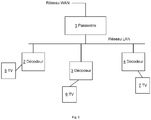
- the figure 1 illustrates a domestic local area network of the LAN type grouping together three television decoders 1, 2, and 3, themselves respectively connected to televisions 5, 6, 7.
- the decoders are devices allowing the reception of audiovisual programs, their recording and their restitution on display devices such as televisions 5, 6 and 7.
- the decoders are connected to the LAN network either by wired (for example Ethernet) or wireless (for example WiFi of the 802.11 type) communication interfaces.
- the home LAN network is connected to an external broadband network of the WAN type (standing for Wide Area Network) via the gateway equipment 1.
- the gateway is for example an ADSL modem router (from the English Asymmetric Digital Subscriber Line) which allows the connection of a household to the Internet network but also, through service providers (operators), the reception of television and video-on-demand programs.
- the decoders 2, 3 and 4 include devices for recording the data received, such as non-volatile memory or a hard disk.
- a decoder having recorded an audiovisual program can, among other functions, serve as a local program server for another decoder through the local home network LAN.
- the decoder which operates, for example, as a program server for another decoder is called a "master" decoder.
- the other decoder which receives the program transmitted by the “master” decoder over the LAN network, is called the “client” decoder.
- Each device should then be kept in a standby mode whenever possible. For example, when a decoder is not recording or playing back a program, it can be put on standby by user action or after it has detected an absence of use over a period of time. predefined.
- the waking of a device is activated when the network interface receives a data frame containing a predefined sequence.
- this type of remote wake-up requires that the network interface be active, which requires that it be powered.
- the consumption of a network interface can reach several watts, which is not optimal with regard to the recommendations and directives aimed at reducing the overall energy consumption and more particularly that of domestic equipment.
- the figure 2 illustrates two decoders interconnected by a local home network.
- the decoder 3 is a “master” decoder capable of operating, for example, as a local program server for the “client” decoder 4.
- the decoder 4 must be able to wake up the decoder 3 if the latter is in a standby mode prior to the request, for example, for transmission of an audiovisual program stored in the decoder 3.
- a decoder has to wake up the other in order to obtain a service that it does not have itself.
- This may for example be data descrambling, remote payment, authentication, or the control of third party equipment connected to the “master” decoder by other interfaces.
- the decoder 4 uses a communication interface with a very low level of electrical consumption to address a message to the decoder 3.
- This interface can be wired or wireless, for example a Bluetooth wireless interface (as described in the IEEE802.15.1 standard) or a Zigbee wireless interface (based on the WPAN 802.15.4 standard; Wireless Personal Area Networks).
- the power consumption level of the low-power interface is sufficiently low compared to the consumption level of an Ethernet interface or an 802.11 interface so that it is possible to maintain it constantly powered, even when the decoder is operating in standby mode.
- the message sent by the decoder 4 and received by the low-consumption interface of the decoder 3 causes the activation of the LAN network interface of the decoder 3.
- the message is for example a message. proprietary type, carried by one or more data frames defined according to the Bluetooth standard.
- the message can equally well be a proprietary message carried by one or more data frames defined according to the Zigbee standard, or any transmission standard defining the exchange of data corresponding to a type of communication interface.
- the message includes an identifier which, interpreted by a wake-up module included in the Bluetooth interface of the decoder 3, causes the activation of a control signal (as described below; see in particular figure 5 ), which signal enables the activation of the local network interface.
- the decoder 3 can then be woken up remotely by sending a magic packet (Wake-on LAN).
- This method of waking up from a two-step standby mode makes it possible both to be able to wake up a decoder in “deep standby” mode, while remaining sensitive and responsive to the reception of a message and to consequently reduce its power consumption in deactivating the interface (s) for connection to the local home network LAN, when switching to standby mode.
- the message sent by the decoder 4 may be a standardized message, defined in a standard corresponding to a type of communication interface, and which is intended to control the output of a standby mode of the device including this type of interface.
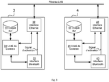
- Decoder 3 includes a control unit 31 which is its digital heart.
- the control unit includes a microprocessor and memories.
- the memories conventionally consist of a non-volatile storage memory where the executable code is located which corresponds to all the applications, routines and drivers supported by the decoder as well as the working memory for storing data specific to the execution of applications.
- the control unit further comprises the conventional functional elements of an audiovisual program decoder, such as the transport interface, the demultiplexer, the content access control, the buffers and the audio and video decoding modules.
- the decoder 3 also comprises a data storage device of the hard disk type for recording programs with a view to their replay or their transmission through the home network LAN.
- the decoder interfaces with the network using the Ethernet interface 32. This interface can be wired or wireless and can receive a magic packet as defined in the Wake-on LAN method for activate a device remotely when it has been placed in a standby mode.
- the possible operating modes of the decoder 3 include a mode in which all the elements are activated, making available all the services and all the functions implemented. Another operating mode of the decoder 3 is such that all the functional elements of the decoder are on standby with the exception of the Bluetooth communication interface 33, the consumption of which is very low. This mode, where only the Bluetooth communication interface 33 is active, results in a very low overall residual consumption of the decoder in standby mode. According to the invention, there is at least one other intermediate mode in which, in addition to the Bluetooth communication interface 33, the connection interface to the LAN network is supplied with power. In the latter mode, consumption is increased, but nevertheless remains lower than that of the decoder when multiple functional elements (or modules) are active and numerous functions are available.
- the decoder 4 is structurally identical to the decoder 3. It comprises a control unit 41, a LAN network interface 42, a low consumption interface 43 and a hard disk 44. Also, it can be used as a “client” decoder in combination with decoder 3 then used as “master” decoder or vice versa as decoder “Master” delivering an audiovisual program to the decoder 3 in “client” mode.
- the decoder 4 in “client” mode When the decoder 4 in “client” mode is preparing to receive an audiovisual program from the decoder 3 operating in standby mode, it remotely controls the exit from standby mode of the decoder 3 according to the method and as follows:
- the unit control 41 of decoder 4 commands the sending of a wake-up message for decoder 3 via the Bluetooth wireless communication interface 43.
- the message is transmitted by radio according to the transmission protocol bluetooth (short distance) in the environment close to the decoder 4.
- the decoder 3 within the range of the transmission field of the interface 43, receives the wake-up message via the Bluetooth communication interface 33.
- the Bluetooth interface 33 of decoder 3 is still active; the other functional elements of decoder 3 are inactive.
- the reception and recognition of the wake-up message by the Bluetooth interface 33 of the decoder 3 causes the change of state of an activation signal of the LAN network interface 32 of the decoder 3.
- the activation signal causes the switching of a power supply circuit of the LAN interface 32.
- the interface 32 comprises one or more integrated circuits having a control input of activation and deactivation making it respectively operational or inoperative and corresponding to a standby and wakeup command of the interface 32.
- the decoder 4 addresses, under the control of the control unit 41 and via its local network interface 42, a wake-up message of the type " magic packet ”, through the local area network LAN.
- the reception of this "magic packet”, specifying the decoder 3 as recipient of the packet, causes the exit from standby mode of the decoder 3 and the activation of the functions necessary for the requested service, such as the transmission of a program stored on the disk. hard 34 to the decoder 4, through its network interface 42, with a view to its decoding and its reproduction.
- the activation of the functions following the reception of a “magic packet” is limited to a predetermined number of functional modules of the device coming out of standby. Activation may, for example, only concern the local area network interface LAN as well as the associated control logic allowing external devices to communicate through the local area network interface LAN. Activation can also, according to another example, relate to a display and keyboard management module, a reception module for the remote control, one or more USB interfaces, a hard disk, a memory module, or any other module. or set of modules integrated into the device.
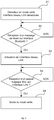
- the figure 4 is a functional diagram which represents the passage from a low consumption standby mode to an operational mode of the decoder according to an embodiment of the invention.
- the decoder is in a standby mode where only the Bluetooth communication interface, with very low energy consumption, is activated.
- the decoder is waiting for a wake-up message via the Bluetooth communication interface.
- the decoder has received a wake-up message and the Bluetooth communication interface checks a signal for activating the local area network interface LAN. The interface is then active and the decoder can be woken up by receiving a magic packet (also usually called “magic packet”) on the LAN network interface.
- a magic packet also usually called “magic packet”
- control signal can act on a supply or clock switching circuitry, or else can be applied to one or more inputs for enabling one or more integrated circuits which constitute all or part of the network interface.
- LAN LAN.
- the decoder is waiting for a magic packet.
- the reception of a magic packet causes the waking up of the decoder and the activation of the required functions.
- a supply module 35 delivers supply lines.
- the power supply lines deliver power to the various functional blocks that make up the decoder.
- a power supply line directly supplies the Bluetooth interface 33 which is permanently energized.
- Another supply line supplies the LAN interface 32 through an activation circuit 39.
- the activation circuit 39 is driven by an activation signal 37 from the LAN interface, generated by the control module. wakeup 330 of the Bluetooth interface 33.
- the other supply lines pass through the supply interface 36 which allows the opening or closing of the lines and therefore the application or not of the corresponding supply voltages to the other units functional (31, 34).
- the power supply interface is driven by the standby output control signal 38, itself generated by the WoL (Wake-on Lan) module 320 of the local area network interface LAN 32.
- the Bluetooth communication interface 33 of the decoder 3 positioned in standby mode can receive a wake-up message.
- the incoming messages are interpreted by the wake-up module 330 of the Bluetooth interface 33.
- the wake-up module 330 positions the activation signal 37 of the local area network interface LAN in order to control the activation circuit 39 to supply power to the local area network interface LAN 32.
- the WoL module of the local area network interface LAN positions the standby output control signal 38 in order to control the power supply interface 36 and to close the lines of power supply in order to power the control unit 31 and hard disk 34 functional blocks and to come out of standby mode.
- the decoder 3 then comes out of standby mode and the functions which require the operation of the control unit 31 and of the hard disk 34 are then available. This is the case, for example, with the transmission of an audiovisual program to another decoder, via the local area network interface LAN 32, with a view to its decoding and its reproduction.
- This wake-up process in two successive steps enables a decoder to be activated by exiting standby mode while eliminating the need for energy consumption inherent in keeping the LAN interface active.
- the energy consumption of the decoder is significantly reduced, which makes it possible to better meet the requirements of the directives aimed at reducing the overall consumption of the stock of domestic equipment.
- the invention described in the context of transmission of a program from one decoder to another decoder through a home network, however relates to any other device having at least two communication interfaces and several operating modes. corresponding to several levels of energy consumption.
- the invention can be applied for example to a computer comprising two communication interfaces such as a WiFi interface and a Bluetooth interface.
- a storage server equipment intended for use on a local network conventionally called NAS (Network Attached Storage), which equipment can be woken up by a computer placed in a nearby environment and using by example a Bluetooth interface to send a first wake-up message and a wired Ethernet or Wifi interface to send a “magic packet”.
- NAS Network Attached Storage
Description
L'invention se rapporte au domaine des récepteurs décodeurs de programmes audiovisuels et plus précisément à la consommation d'énergie en mode veille et à la sortie du mode veille.The invention relates to the field of audiovisual program decoder receivers and more specifically to the consumption of energy in standby mode and on exiting standby mode.
Les récepteurs / décodeurs de programmes audiovisuels offrent de plus en plus de fonctionnalités à l'utilisateur. Il existe différents types de décodeurs se dissociant par leur interface d'entrée. Certains se connectent à une prise d'antenne permettant la réception d'un signal TNT (de Télévision Numérique Terrestre), d'autres sont connectés à un réseau câblé mis en place par un opérateur et d'autres encore disposent d'une interface d'entrée réseau pour la connexion à un réseau local domestique ou à un modem routeur lui-même connecté à internet. Dans ce dernier cas, le décodeur est destiné à une réception IPTV (de l'anglais Internet Protocol TeleVision). Il existe également des décodeurs hybrides, dotés de plusieurs interfaces d'entrée comme, par exemple, un tuner TNT et une interface réseau Ethernet (IEEE802.3). Dans ce cas le décodeur peut recevoir et restituer un programme reçu par l'une ou l'autre des interfaces.Audiovisual program receivers / decoders offer more and more functions to the user. There are different types of decoders that are separated by their input interface. Some connect to an antenna socket allowing reception of a TNT (Digital Terrestrial Television) signal, others are connected to a cable network set up by an operator and still others have a digital interface. 'network input for connection to a local home network or to a modem router which is itself connected to the Internet. In the latter case, the decoder is intended for IPTV (Internet Protocol TeleVision) reception. There are also hybrid decoders, equipped with several input interfaces such as, for example, a TNT tuner and an Ethernet network interface (IEEE802.3). In this case, the decoder can receive and restore a program received by one or the other of the interfaces.
Le développement croissant des produits numériques à usage domestique, tel que, par exemple, la télévision, les ordinateurs, les organiseurs, les téléphones mobiles, les dispositifs de stockage de données, les imprimantes, est tel qu'il est avantageux de les interconnecter par l'intermédiaire d'un réseau domestique. Ce type de réseau local, communément appelé LAN (de l'anglais Local Area Network) peut-être filaire (par exemple avec une connexion de type Ethernet), sans-fil (avec par exemple une connexion Wifi) ou associer les deux types d'interconnexion entre les dispositifs qui y sont raccordés.The increasing development of digital products for home use, such as, for example, television, computers, organizers, mobile phones, data storage devices, printers, is such that it is advantageous to interconnect them by through a home network. This type of local network, commonly called LAN (from the English Local Area Network) can be wired (for example with an Ethernet type connection), wireless (with for example a Wifi connection) or combine the two types of network. 'interconnection between the devices connected to it.
Il existe aujourd'hui des configurations associant plusieurs décodeurs de programmes audiovisuels dans un même foyer. Des fonctionnalités sont alors disponibles à l'utilisateur, telles que le partage des programmes audiovisuels ou la possibilité de regarder plusieurs programmes différents sur plusieurs téléviseurs connectés respectivement à plusieurs décodeurs, par exemple dans différentes pièces de la maison.Today there are configurations associating several audiovisual program decoders in the same home. From functionalities are then available to the user, such as the sharing of audiovisual programs or the possibility of watching several different programs on several televisions connected respectively to several decoders, for example in different rooms of the house.
Il existe ainsi des configurations où un décodeur connecté à la source du signal est de type « maître » et d'autres décodeurs dits « clients », connectés au décodeur « maître » par l'intermédiaire d'un réseau local, peuvent se voir transmettre les données correspondant à un programme audiovisuel depuis le décodeur « maître », en vue de sa restitution.There are thus configurations where a decoder connected to the source of the signal is of the “master” type and other so-called “client” decoders, connected to the “master” decoder via a local network, can be transmitted. the data corresponding to an audiovisual program from the “master” decoder, with a view to its reproduction.
Si des configurations incluant un grand nombre de dispositifs interconnectés permettent à l'utilisateur de bénéficier de fonctionnalités confortables, elles induisent cependant une grande consommation d'énergie par la multiplication des dispositifs. Aussi, il devient de plus en plus important de maîtriser la consommation d'énergie des dispositifs à usage domestique mais aussi la consommation d'énergie de l'ensemble d'une installation et plus largement de l'ensemble d'un foyer.If configurations including a large number of interconnected devices allow the user to benefit from comfortable functions, they nevertheless induce a large consumption of energy by the multiplication of devices. Also, it is becoming increasingly important to control the energy consumption of devices for domestic use but also the energy consumption of an entire installation and more generally of an entire household.
Il existe aujourd'hui des directives en termes de consommation d'énergie. Ces directives sont à considérer avec attention lors des étapes de conception des dispositifs grand-public.There are now guidelines in terms of energy consumption. These guidelines should be carefully considered during the design stages of consumer devices.
Dans le cas d'une installation où des décodeurs sont interconnectés et où un décodeur « maître » est utilisé comme serveur de programmes audiovisuels pour un décodeur « client », il n'est pas concevable de devoir maintenir dans un état de consommation important le décodeur « maître » lorsqu'il n'est pas utilisé. Un décodeur « client » souhaitant recevoir un programme audiovisuel depuis un décodeur « maître » doit pouvoir le réveiller si ce dernier est en mode veille, lui permettant ainsi d'être en mode veille aussi souvent que possible. Cette opération de réveil du décodeur « maître » peut se faire par l'intermédiaire du réseau local. Un décodeur client adresse par exemple un message au décodeur « maître » afin de lui demander de sortir du mode veille et de fournir le ou les services sollicités.In the case of an installation where decoders are interconnected and where a "master" decoder is used as an audiovisual program server for a "client" decoder, it is not conceivable to have to keep the decoder in a high consumption state. "Master" when not in use. A “client” decoder wishing to receive an audiovisual program from a “master” decoder must be able to wake it up if the latter is in standby mode, thus allowing it to be in standby mode as often as possible. This operation of waking up the “master” decoder can be done via the local network. A client decoder for example sends a message to the “master” decoder in order to ask it to come out of standby mode and to provide the requested service (s).
La contrainte de réduction importante de la consommation d'énergie, couplée à la nécessité de pouvoir réveiller les dispositifs crée une problématique. Il est nécessaire de disposer de modes veilles correspondant à des consommations d'énergie les plus faibles possibles et nécessaire de pouvoir réveiller un dispositif considérant que les interfaces ou modules utilisés pour le réveil sont consommateurs d'énergie.The constraint of significantly reducing energy consumption, coupled with the need to be able to wake up the devices, creates a problem. It is necessary to have standby modes corresponding to the lowest possible energy consumption and necessary to be able to wake up a device considering that the interfaces or modules used for the alarm clock consume energy.
Lorsqu'une sortie de mode veille d'un dispositif est contrôlée par l'intermédiaire de son interface réseau (par exemple Ethernet ou Wifi), l'interface réseau consomme plusieurs watts. Cette consommation pénalise l'économie d'énergie en mode veille.When a device wakes from sleep mode controlled through its network interface (eg Ethernet or Wifi), the network interface consumes several watts. This consumption penalizes energy saving in standby mode.
De l'art antérieur, on connait le document
On connait également le document
Enfin, le document
L'invention permet de résoudre au moins un des inconvénients de l'art antérieur en optimisant la consommation en mode veille d'un dispositif tout en permettant de contrôler la sortie du mode veille par l'intermédiaire d'une interface.The invention makes it possible to resolve at least one of the drawbacks of the prior art by optimizing the consumption in standby mode of a device while making it possible to control the exit from standby mode via an interface.
Plus particulièrement l'invention concerne un procédé de contrôle d'un dispositif, le dispositif opérant dans plusieurs modes de fonctionnement correspondant à différents niveaux de consommation d'énergie et comprenant une première et une seconde interface de communication, le procédé étant caractérisé en ce qu'il comprend, dans le dispositif les étapes d'activation de la seconde interface de communication sur réception d'un premier message de réveil par la première interface lorsque le dispositif est dans un premier mode de fonctionnement correspondant à un premier niveau de consommation d'énergie, l'activation entrainant un second niveau de consommation d'énergie supérieur au premier niveau de consommation d'énergie, de réception d'un second message de réveil par la seconde interface de communication, le second message de réveil entrainant une fermeture de lignes d'alimentation en vue d'alimenter des blocs fonctionnels dudit dispositif, une sortie d'un mode veille, et conséquemment un passage du dispositif dans un mode de fonctionnement correspondant à un troisième niveau de consommation d'énergie, le troisième niveau de consommation d'énergie étant supérieur au second niveau de consommation d'énergie.More particularly, the invention relates to a method of controlling a device, the device operating in several operating modes corresponding to different levels of energy consumption and comprising a first and a second communication interface, the method being characterized in that 'it comprises, in the device, the steps of activating the second communication interface on receipt of a first wake-up message by the first interface when the device is in a first operating mode corresponding to a first level of consumption of energy, the activation leading to a second level of energy consumption higher than the first level of consumption energy, of reception of a second wake-up message by the second communication interface, the second wake-up message causing a closure of the supply lines with a view to supplying the functional blocks of said device, an exit from a mode standby, and consequently switching the device to an operating mode corresponding to a third level of energy consumption, the third level of energy consumption being greater than the second level of energy consumption.
Selon un mode de réalisation de l'invention, le premier mode de fonctionnement correspond à une configuration du dispositif dans laquelle seule la première interface est activée.According to one embodiment of the invention, the first mode of operation corresponds to a configuration of the device in which only the first interface is activated.
Selon un mode de réalisation de l'invention, le second mode de fonctionnement correspond à une configuration du dispositif dans laquelle seules les première et seconde interfaces sont activées.According to one embodiment of the invention, the second operating mode corresponds to a configuration of the device in which only the first and second interfaces are activated.
Selon un mode de réalisation de l'invention, la première interface est une interface de communication sans-fil.According to one embodiment of the invention, the first interface is a wireless communication interface.
Selon un mode de réalisation de l'invention, la seconde interface est une interface de réseau de type Ethernet.According to one embodiment of the invention, the second interface is an Ethernet type network interface.
Selon un mode de réalisation de l'invention, la seconde interface est une interface de réseau sans fil, compatible avec les normes de transmission 802.11.According to one embodiment of the invention, the second interface is a wireless network interface, compatible with the 802.11 transmission standards.
L'invention concerne également un dispositif opérant dans plusieurs modes de fonctionnement correspondant à différents niveaux de consommation d'énergie et comprenant une première et une seconde interface de communication, le dispositif étant caractérisé en ce qu'il comprend en outre des moyens d'activation de la seconde interface sur réception, par la première interface d'un premier message de réveil lorsque le dispositif est dans un premier mode de fonctionnement correspondant à un premier niveau de consommation d'énergie, l'activation entrainant un second niveau de consommation d'énergie supérieur au premier niveau de consommation d'énergie et des moyens de contrôle du dispositif sur réception par la seconde interface d'un second message de réveil, le second message de réveil entrainant une fermeture de lignes d'alimentation en vue d'alimenter des blocs fonctionnels dudit dispositif, une sortie d'un mode veille, et conséquemment un passage du dispositif dans un mode de fonctionnement correspondant à un troisième niveau de consommation d'énergie, le troisième niveau de consommation d'énergie étant supérieur au second niveau de consommation d'énergie.The invention also relates to a device operating in several operating modes corresponding to different levels of energy consumption and comprising a first and a second communication interface, the device being characterized in that it further comprises activation means. of the second interface on reception, by the first interface of a first wake-up message when the device is in a first operating mode corresponding to a first level of energy consumption, the activation causing a second level of energy consumption. energy greater than the first level of energy consumption and control means of the device on reception by the second interface of a second wake-up message, the second wake-up message causing the power lines to close with a view to supplying power to functional blocks of said device, an exit from a standby mode, and consequently a passage of the device into an operating mode t corresponding to a third level of energy consumption, the third level of energy consumption being greater than the second level of energy consumption.
Avantageusement, le premier message de réveil adressé à la première interface et le second message de réveil adressé à la seconde interface peuvent être émis par des dispositifs différents, ce qui offre une grande souplesse dans l'implémentation de fonctions nécessitant des interactions entre plusieurs dispositifs.Advantageously, the first wake-up message addressed to the first interface and the second wake-up message addressed to the second interface can be transmitted by different devices, which offers great flexibility in the implementation of functions requiring interactions between several devices.
Un des avantages apportés par l'invention est la facilité de mise en œuvre de l'invention dans la conception d'un produit disposant de deux interfaces de communication et considérant l'architecture classique d'un récepteur de programmes audiovisuels. L'architecture classique d'un produit grand-public de ce type, ainsi que l'implémentation des différents modes de fonctionnement (par exemple mode veille profonde, mode veille avec réseau, mode décodeur, mode toutes fonctions) est telle qu'il est très simple, lors d'une nouvelle phase de conception, d'adapter une architecture existante pour intégrer l'invention est permettre ensuite, lors de l'utilisation du produit, le réveil d'un équipement depuis un autre équipement sans avoir à alimenter l'interface réseau en mode veille.One of the advantages provided by the invention is the ease of implementation of the invention in the design of a product having two communication interfaces and considering the conventional architecture of an audiovisual program receiver. The classic architecture of a consumer product of this type, as well as the implementation of the different operating modes (for example deep standby mode, standby mode with network, decoder mode, full function mode) is such that it is very simple, during a new design phase, to adapt an existing architecture to integrate the invention is then to allow, when using the product, the wake-up of a device from another device without having to power the network interface in standby mode.
L'invention sera mieux comprise, et d'autres particularités et avantages apparaîtront à la lecture de la description qui va suivre, la description faisant référence aux dessins annexés parmi lesquels :
- la
figure 1 illustre un réseau domestique, selon un mode de réalisation particulier de l'invention ; - la
figure 2 illustre un décodeur « maître » et un décodeur « client » couplés par un réseau local domestique tel que celui de lafigure 1 , selon un mode de réalisation de l'invention. - la
figure 3 illustre schématiquement les décodeurs de lafigure 2 et détaille leur architecture. - la
figure 4 est un diagramme fonctionnel représentant les étapes successives qui constituent la sortie de veille du décodeur de programmes. - la
figure 5 illustre les signaux de contrôles utilisés pour la sortie du mode veille dans un décodeur tel que représenté sur lafigure 3 et dans un mode de réalisation de l'invention.
- the
figure 1 illustrates a home network, according to a particular embodiment of the invention; - the
figure 2 illustrates a "master" decoder and a "client" decoder coupled by a domestic local area network such as that of thefigure 1 , according to one embodiment of the invention. - the
figure 3 schematically illustrates the decoders of thefigure 2 and details their architecture. - the
figure 4 is a functional diagram representing the successive steps which constitute the exit from standby of the program decoder. - the
figure 5 illustrates the control signals used to exit standby mode in a decoder as shown in Figurefigure 3 and in one embodiment of the invention.
Sur les
De manière générale mais non limitative, l'invention concerne un procédé de contrôle des modes de fonctionnement d'un décodeur de programmes audiovisuels et notamment le passage du décodeur d'un mode veille basse consommation à une mode fonctionnel dans lequel une connexion à un réseau local est active.In general but not restrictively, the invention relates to a method of controlling the operating modes of an audiovisual program decoder and in particular the passage of the decoder from a low-consumption standby mode to a functional mode in which a connection to a network local is active.
La
Dans le cas où un utilisateur se sert d'un décodeur « client » pour visualiser un programme audiovisuel stocké par un décodeur « maître » et que le décodeur « maître » est positionné dans un mode de veille, il est nécessaire de réveiller le décodeur « maître ». Dans ce type de configuration où plusieurs équipements sont interconnectés par le biais d'un réseau LAN, il est fréquent pour un équipement d'utiliser le réseau pour adresser une commande de sortie de mode veille (ou commande de « réveil ») à un autre équipement. L'envoi d'un « paquet magique » est un procédé connu pour ce type d'activation à distance baptisé « Wake-on LAN » ou « WoL» (de l'anglais) et décrit dans le document «White Paper» (White Paper : Wake on LAN Technology de Lieberman Software, révision 2, daté du 1er juin 2006). Par ce procédé, le réveil d'un équipement est activé lorsque l'interface réseau reçoit une trame de données contenant une séquence prédéfinie. Ce type de réveil à distance requiert toutefois que l'interface réseau soit active, ce qui nécessite qu'elle soit alimentée. La consommation d'une interface réseau peut atteindre plusieurs watts, ce qui n'est pas optimal au regard des recommandations et directives visant à diminuer la consommation d'énergie globale et plus particulièrement celle des équipements domestiques.In the event that a user uses a "client" decoder to view an audiovisual program stored by a "master" decoder and the "master" decoder is positioned in a standby mode, it is necessary to wake up the "decoder". master ". In this type of configuration where several devices are interconnected via a LAN network, it is common for one device to use the network to send a command to exit from standby mode (or "wake-up" command) to another. equipment. Sending a "magic packet" is a known process for this. type of remote activation called "Wake-on LAN" or "WoL" and described in the document "White Paper" (White Paper: Wake on LAN Technology from Lieberman Software, revision 2, dated 1 June 2006). By this method, the waking of a device is activated when the network interface receives a data frame containing a predefined sequence. However, this type of remote wake-up requires that the network interface be active, which requires that it be powered. The consumption of a network interface can reach several watts, which is not optimal with regard to the recommendations and directives aimed at reducing the overall energy consumption and more particularly that of domestic equipment.
La
Selon un mode de réalisation de l'invention et pour s'affranchir des consommations induites par les interfaces réseau LAN telles qu'un module Wifi ou une interface Ethernet, le décodeur 4 utilise une interface de communication à très faible niveau de consommation électrique pour adresser un message au décodeur 3. Cette interface peut être filaire ou sans fil, comme par exemple une interface sans fil Bluetooth (telle que décrit dans le standard IEEE802.15.1) ou une interface sans fil Zigbee (basée sur la norme WPAN 802.15.4 ; Wireless Personal Area Networks). Le niveau de consommation électrique de l'interface basse-consommation est suffisamment faible devant le niveau de consommation d'une interface Ethernet ou une interface 802.11 pour qu'il soit possible de la maintenir alimentée constamment, y compris quand le décodeur opère en mode veille.According to one embodiment of the invention and to overcome the consumption induced by the LAN network interfaces such as a WiFi module or an Ethernet interface, the
Selon un mode de réalisation de l'invention, le message émis par le décodeur 4 et reçu par l'interface basse-consommation du décodeur 3 entraine l'activation de l'interface réseau LAN du décodeur 3. Le message est par exemple un message de type propriétaire, porté par une ou plusieurs trames de données définies selon la norme Bluetooth. Le message peut aussi bien être un message propriétaire porté par une ou plusieurs trames de données définies selon la norme Zigbee, ou n'importe quelle norme de transmission définissant l'échange de données correspondant à un type d'interface de communication. Le message comprend un identifiant qui, interprété par un module de réveil compris dans l'interface Bluetooth du décodeur 3, entraine l'activation d'un signal de contrôle (tel que décrit plus loin ; voir notamment
Selon un autre mode de réalisation de l'invention, le message émis par le décodeur 4 peut-être un message standardisé, défini dans une norme correspondant à un type d'interface de communication, et qui a vocation à contrôler la sortie d'un mode de veille du dispositif comprenant ce type d'interface.According to another embodiment of the invention, the message sent by the
La
Le décodeur 4 est structurellement identique au décodeur 3. Il comprend une unité de contrôle 41, une interface de réseau LAN 42, une interface basse consommation 43 et un disque dur 44. Aussi, il peut être utilisé comme décodeur « client » en combinaison avec le décodeur 3 alors utilisé comme décodeur « maître » ou inversement comme décodeur « maître » délivrant un programme audiovisuel au décodeur 3 en mode « client ».The
Lorsque le décodeur 4 en mode « client » s'apprête à recevoir un programme audiovisuel depuis le décodeur 3 opérant en mode veille, il commande à distance la sortie du mode veille du décodeur 3 selon le procédé et de la façon suivante : L'unité de contrôle 41 du décodeur 4 commande l'envoi d'un message de réveil à l'intention du décodeur 3 par l'intermédiaire de l'interface de communication sans-fil Bluetooth 43. Le message est transmis par radio selon le protocole de transmission bluetooth (courte distance) dans l'environnement proche du décodeur 4. Le décodeur 3, dans la portée du champ de transmission de l'interface 43, reçoit le message de réveil par l'interface de communication Bluetooth 33. L'interface Bluetooth 33 du décodeur 3 est toujours active ; les autres éléments fonctionnels du décodeur 3 sont inactifs. La réception et la reconnaissance du message de réveil par l'interface Bluetooth 33 du décodeur 3 entraine le changement d'état d'un signal d'activation de l'interface réseau LAN 32 du décodeur 3. Selon un mode de réalisation de l'invention, le signal d'activation entraine la commutation d'un circuit d'alimentation de l'interface LAN 32. Selon un autre mode de réalisation, l'interface 32 comprend un ou plusieurs circuits intégrés disposant d'une entrée de commande d'activation et de désactivation la rendant respectivement opérante ou inopérante et correspondant à une commande mise en veille et de réveil de l'interface 32. L'assertion du signal d'activation entre l'interface basse consommation 33 et l'interface de réseau local LAN 32 rend l'interface réseau 32 sensible et réactive à la détection d'un message de réveil de type Wake-on LAN qui lui serait adressée au travers du réseau LAN. Après un délai supérieur au temps d'activation de l'interface LAN 32, le décodeur 4 adresse, sous contrôle de l'unité de contrôle 41 et par l'intermédiaire de son interface de réseau local 42, un message de réveil de type « paquet magique », par l'intermédiaire du réseau local LAN. La réception de ce « paquet magique », spécifiant le décodeur 3 comme destinataire du paquet, entraine la sortie de mode veille du décodeur 3 et l'activation des fonctions nécessaire au service demandé, tel que la transmission d'un programme stocké sur le disque dur 34 vers le décodeur 4, à travers son interface réseau 42, en vue de son décodage et de sa restitution.When the
Avantageusement, l'activation des fonctions suite à la réception d'un « paquet magique » est limitée à un nombre prédéterminé de modules fonctionnels du dispositif sortant de veille. L'activation peut, par exemple, ne concerner que l'interface de réseau local LAN ainsi que la logique de contrôle associée permettant à des dispositifs externes de communiquer par le biais de l'interface de réseau local LAN. L'activation peut également, selon un autre exemple, concerner un module d'affichage et de gestion de clavier, un module de réception pour la télécommande, une ou plusieurs interfaces USB, un disque dur, un module de mémoire, ou tout autre module ou ensemble de modules intégrés au dispositif. L'activation d'un sous-ensemble seulement des modules fonctionnels d'un dispositif et la disponibilité qui en découle d'un sous-ensemble des fonctions et services disponibles à l'utilisateur, crée de fait une pluralité de modes fonctionnels différents, qui se caractérisent, entre autres, pas les possibilités offertes à l'utilisateur et par la consommation d'énergie propre à chacun des modes.Advantageously, the activation of the functions following the reception of a “magic packet” is limited to a predetermined number of functional modules of the device coming out of standby. Activation may, for example, only concern the local area network interface LAN as well as the associated control logic allowing external devices to communicate through the local area network interface LAN. Activation can also, according to another example, relate to a display and keyboard management module, a reception module for the remote control, one or more USB interfaces, a hard disk, a memory module, or any other module. or set of modules integrated into the device. The activation of only a subset of the functional modules of a device and the resulting availability of a subset of the functions and services available to the user, in fact creates a plurality of different functional modes, which are characterized, among other things, by the possibilities offered to the user and by the energy consumption specific to each mode.
La
La
Selon un mode de réalisation de l'invention, l'interface de communication Bluetooth 33 du décodeur 3 positionné en mode de veille peut recevoir un message de réveil. Les messages entrants sont interprétés par le module de réveil 330 de l'interface Bluetooth 33. Dans le cas où un message reçu est interprété comme un message de réveil à destination du décodeur 3, par exemple par la reconnaissance d'un identifiant spécifique dans une trame de données, le module de réveil 330 positionne le signal d'activation 37 de l'interface de réseau local LAN afin de commander le circuit d'activation 39 pour alimenter l'interface de réseau local LAN 32. Ensuite, et à la réception d'un « paquet magique » destiné au décodeur 3, le module WoL de l'interface de réseau local LAN positionne le signal de contrôle de sortie de veille 38 afin de contrôler l'interface d'alimentation 36 et de fermer les lignes d'alimentation en vue d'alimenter les blocs fonctionnels unité de contrôle 31 et disque dur 34 et de sortir du mode veille. Le décodeur 3 sort alors du mode de veille et les fonctionnalités qui requièrent le fonctionnement de l'unité de contrôle 31 et du disque dur 34 sont alors disponibles. C'est le cas, par exemple, de la transmission d'un programme audiovisuel à un autre décodeur, par l'intermédiaire de l'interface de réseau local LAN 32, en vue de son décodage et de sa restitution.According to one embodiment of the invention, the
Ce procédé de réveil en deux étapes successives permet d'activer un décodeur en sortant du mode veille tout en s'affranchissant de la consommation d'énergie inhérente au maintien en activité de l'interface réseau LAN.This wake-up process in two successive steps enables a decoder to be activated by exiting standby mode while eliminating the need for energy consumption inherent in keeping the LAN interface active.
La consommation d'énergie du décodeur en est sensiblement diminuée, ce qui permet de mieux répondre aux exigences des directives visant à réduire la consommation global du parc des équipements domestiques.The energy consumption of the decoder is significantly reduced, which makes it possible to better meet the requirements of the directives aimed at reducing the overall consumption of the stock of domestic equipment.
L'invention, décrite dans le cadre d'une transmission d'une programme d'un décodeur à un autre décodeur à travers un réseau domestique, concerne cependant tout autre dispositif disposant d'au moins deux interfaces de communication et de plusieurs modes de fonctionnement correspondant à plusieurs niveaux de consommation d'énergie.The invention, described in the context of transmission of a program from one decoder to another decoder through a home network, however relates to any other device having at least two communication interfaces and several operating modes. corresponding to several levels of energy consumption.
L'invention peut s'appliquer par exemple à un ordinateur comprenant deux interfaces de communication telles qu'une interface Wifi et une interface Bluetooth. Un autre exemple d'application est un équipement serveur de stockage destiné à être utilisé sur un réseau local, classiquement appelé NAS (de l'anglais Network Attached Storage), lequel équipement peut être réveillé par un ordinateur placé dans un environnement proche et utilisant par exemple une interface Bluetooth pour adresser un premier message de réveil et une interface Ethernet filaire ou Wifi pour adresser un « paquet magique ».The invention can be applied for example to a computer comprising two communication interfaces such as a WiFi interface and a Bluetooth interface. Another example of an application is a storage server equipment intended for use on a local network, conventionally called NAS (Network Attached Storage), which equipment can be woken up by a computer placed in a nearby environment and using by example a Bluetooth interface to send a first wake-up message and a wired Ethernet or Wifi interface to send a “magic packet”.
Claims (12)
- Method for controlling a device (3), said device (3) operating in several operating modes corresponding to different levels of power consumption and comprising a first and a second communication interface (33, 32), said method being characterised in that it comprises, in said device the steps of:- activating (S3) said second communication interface upon receiving (S2) a first wake-up message via said first interface when said device is in a first operating mode (S1) corresponding to a first level of power consumption, said activation resulting in a second level of power consumption higher than said first level of power consumption.- receiving (S4) a second wake-up message via said second communication interface, said second wake-up message resulting in the closure of power supply lines with a view to supplying power to functional blocks of said device, an exit from the standby mode, and consequently a transition of said device to an operating mode corresponding to a third level of power consumption, said third level of power consumption being higher than said second level of power consumption.
- Method according to claim 1, characterised in that said first operating mode corresponds to a configuration of said device wherein only said first interface is activated.
- Method according to one of claims 1 to 2, characterised in that said second operating mode corresponds to a configuration of said device wherein only said first and second interface are activated.
- Method according to one of claims 1 to 3, characterised in that said first interface is a wireless communication interface.
- Method according to one of claims 1 to 4, characterised in that said second interface is a network interface of Ethernet type.
- Method according to one of claims 1 to 5, characterised in that said second interface is a wireless network interface, compatible with the 802.11 transmission standards.
- Device (3) operating in several operating modes corresponding to different levels of power consumption and comprising a first and a second communication interface (33,32), said device (3) being characterised in that it further comprises:- means for activating (330, 37, 39) said second interface (32) upon receiving, via said first interface (33) a first wake-up message when said device is in a first operating mode corresponding to a first level of power consumption, said activation resulting in a second level of power consumption higher than said first level of power consumption;- means for controlling (320, 38, 36) said device (3) upon receiving via said second interface (32) a second wake-up message, said second wake-up message resulting in the closure of power supply lines with a view to supplying power to functional blocks of said device, an exit from the standby mode, and consequently a transition of said device to an operating mode corresponding to a third level of power consumption, said third level of power consumption being higher than said second level of power consumption.
- Device according to claim 7, characterised in that said first operating mode corresponds to a configuration of said device wherein only said first interface (33) is activated.
- Device according to one of claims 7 to 8, characterised in that said second operating mode corresponds to a configuration of said device wherein only said first (33) and second (32) interface are activated.
- Device according to one of claims 7 to 9, characterised in that said first interface (33) is a wireless communication interface.
- Device according to one of claims 7 to 10, characterised in that said second interface (32) is a network interface of Ethernet type.
- Device according to one of claims 7 to 11, characterised in that said second interface (32) is a wireless network interface, compatible with the 802.11 transmission standards.
Applications Claiming Priority (2)
| Application Number | Priority Date | Filing Date | Title |
|---|---|---|---|
| FR1155061 | 2011-06-09 | ||
| PCT/EP2012/060839 WO2012168391A1 (en) | 2011-06-09 | 2012-06-07 | Method for exiting a low-consumption standby mode, and associated device |
Publications (2)
| Publication Number | Publication Date |
|---|---|
| EP2719188A1 EP2719188A1 (en) | 2014-04-16 |
| EP2719188B1 true EP2719188B1 (en) | 2021-10-13 |
Family
ID=46331281
Family Applications (1)
| Application Number | Title | Priority Date | Filing Date |
|---|---|---|---|
| EP12729081.5A Active EP2719188B1 (en) | 2011-06-09 | 2012-06-07 | Method for exiting a low-consumption standby mode, and associated device |
Country Status (7)
| Country | Link |
|---|---|
| US (1) | US10009842B2 (en) |
| EP (1) | EP2719188B1 (en) |
| JP (1) | JP2014522146A (en) |
| KR (1) | KR20140039028A (en) |
| CN (1) | CN103597845A (en) |
| BR (1) | BR112013030634B1 (en) |
| WO (1) | WO2012168391A1 (en) |
Families Citing this family (11)
| Publication number | Priority date | Publication date | Assignee | Title |
|---|---|---|---|---|
| DE102014216444A1 (en) * | 2014-08-19 | 2016-02-25 | Volkswagen Aktiengesellschaft | Switch unit, Ethernet network and method for activating components in an Ethernet network |
| US9510281B2 (en) * | 2014-09-19 | 2016-11-29 | Qualcomm Incorporated | Priority arbitration for interference mitigation |
| US9826272B2 (en) * | 2014-10-20 | 2017-11-21 | Echostar Technologies L.L.C. | Remote mode selection for a set-top box |
| CN105472449A (en) * | 2015-12-11 | 2016-04-06 | 四川长虹网络科技有限责任公司 | Method for simultaneously closing smart set-top box and smart TV |
| FR3058241B1 (en) * | 2016-10-28 | 2019-11-08 | Sagemcom Broadband Sas | METHOD FOR MANAGING AN OPERATING MODE OF AN EQUIPMENT |
| CN106792127A (en) * | 2016-12-19 | 2017-05-31 | 深圳Tcl数字技术有限公司 | Network wake-up method and device, wake-up terminal and television set |
| WO2018157437A1 (en) * | 2017-03-02 | 2018-09-07 | 华为技术有限公司 | Method and device for waking up wireless device |
| EP3656183A4 (en) * | 2017-07-18 | 2021-02-24 | Hewlett-Packard Development Company, L.P. | Device management |
| KR102453689B1 (en) | 2017-12-13 | 2022-10-11 | 삼성전자주식회사 | Periodical process performing system and system on chip |
| JP7293950B2 (en) * | 2019-07-31 | 2023-06-20 | ブラザー工業株式会社 | Terminal and computer program for terminal |
| CN112165352B (en) * | 2020-09-24 | 2021-04-16 | 天宸星通(深圳)科技有限公司 | Interaction method for satellite Internet of things terminal |
Family Cites Families (43)
| Publication number | Priority date | Publication date | Assignee | Title |
|---|---|---|---|---|
| US6678831B1 (en) * | 1997-12-11 | 2004-01-13 | Hewlett-Packard Development Company, L.P. | Managing power states in a computer system |
| JP2004503988A (en) * | 2000-06-13 | 2004-02-05 | レッド−エム(コミュニケーションズ)リミテッド | Communication device |
| JP4481511B2 (en) * | 2000-08-18 | 2010-06-16 | 富士通株式会社 | Information device, information device control method, and control method program |
| JP2004038295A (en) | 2002-06-28 | 2004-02-05 | Toshiba Corp | Information processor and power supply control method |
| US7269629B2 (en) | 2002-12-30 | 2007-09-11 | Intel Corporation | Method and apparatus for distributing notification among cooperating devices and device channels |
| US7114090B2 (en) * | 2003-02-14 | 2006-09-26 | Intel Corporation | Computing system with operational low power states |
| US7080271B2 (en) * | 2003-02-14 | 2006-07-18 | Intel Corporation | Non main CPU/OS based operational environment |
| US7194642B2 (en) * | 2003-08-04 | 2007-03-20 | Intel Corporation | Technique to coordinate servicing of multiple network interfaces |
| EP1545051A1 (en) | 2003-12-15 | 2005-06-22 | Alcatel | Method for waking up a sleeping device, a related network element and a related waking device |
| US8199686B1 (en) * | 2004-03-04 | 2012-06-12 | Marvell International Ltd. | Wireless local area network infrastructure mode for reducing power consumption |
| TW200503471A (en) | 2004-09-03 | 2005-01-16 | Cameo Infotech Inc | System and method using wireless signal to wake up mobile device for program execution |
| WO2006038094A1 (en) * | 2004-10-06 | 2006-04-13 | Nokia Corporation | Distributed link-layer wake-up agent system, method and device for universal plug and play function with lower power proxy |
| US20060202804A1 (en) * | 2005-03-09 | 2006-09-14 | Intermec Ip Corp., | Sleep command for active RF tags to prolong battery life |
| JP4356997B2 (en) * | 2005-03-15 | 2009-11-04 | キヤノン株式会社 | Communication apparatus and communication method thereof |
| US7525436B2 (en) * | 2005-04-21 | 2009-04-28 | University Of Pittsburgh-Of The Commonwealth System Of Higher Education | Methods and apparatus for reducing power consumption of an active transponder |
| US7571332B2 (en) | 2005-06-13 | 2009-08-04 | Lenovo (Singapore) Pte. Ltd. | Reducing power consumed by a computer system during a hibernation or an off state by remotely waking up the computer system |
| US7447927B2 (en) | 2005-08-23 | 2008-11-04 | Apple Inc. | Method and apparatus for waking up a sleeping system |
| KR101205324B1 (en) * | 2005-11-25 | 2012-11-28 | 삼성전자주식회사 | Methods for controlling power of system with serial interface manner |
| US7929912B2 (en) * | 2006-04-04 | 2011-04-19 | Texas Instruments Incorporated | Apparatus for and method of Bluetooth and WiMAX coexistence in a mobile handset |
| US20080215360A1 (en) * | 2006-10-24 | 2008-09-04 | Kent Dicks | Systems and methods for medical data interchange interface |
| US8126734B2 (en) * | 2006-10-24 | 2012-02-28 | Medapps, Inc. | Systems and methods for adapter-based communication with a medical device |
| CN101261534B (en) | 2007-03-07 | 2012-10-03 | 创杰科技股份有限公司 | Bidirectional wireless perimeter set electricity-saving method |
| CN101578571A (en) | 2007-07-09 | 2009-11-11 | 索尼株式会社 | Electronic apparatus and method for controlling the same |
| US20090073481A1 (en) | 2007-09-17 | 2009-03-19 | Ferlitsch Andrew R | Method and system for external preprocessing of service requests directed to a sleeping node |
| JP2009111738A (en) | 2007-10-30 | 2009-05-21 | Victor Co Of Japan Ltd | Network conversion transmission control apparatus |
| US8095667B1 (en) * | 2008-02-19 | 2012-01-10 | Marvell International Ltd. | Methods and apparatus for remotely waking up a computer system on a computer network |
| KR100956377B1 (en) | 2008-03-03 | 2010-05-07 | 삼성전기주식회사 | Low power communication system and communication method thereof |
| EP2283650A1 (en) | 2008-05-26 | 2011-02-16 | Koninklijke Philips Electronics N.V. | A method for switching a multimedia source and multimedia sink from an operating mode to a standby mode, and from a standby mode to an operating mode |
| US8510577B2 (en) * | 2008-07-28 | 2013-08-13 | Microsoft Corporation | Reducing power consumption by offloading applications |
| JP5448403B2 (en) * | 2008-09-29 | 2014-03-19 | キヤノン株式会社 | COMMUNICATION DEVICE, ITS CONTROL METHOD, AND COMPUTER PROGRAM |
| KR101008473B1 (en) | 2008-10-30 | 2011-01-14 | 삼성전기주식회사 | Zigbee device comprising a sleep mode and an active mode; and wake-up method comprising an sleep mode |
| US8447368B2 (en) * | 2008-11-13 | 2013-05-21 | Lantiq Deutschland Gmbh | Base station, method of operating a base station and wireless communication system |
| TW201020750A (en) * | 2008-11-20 | 2010-06-01 | Inventec Corp | Thin client and thin client wake up method |
| KR101139223B1 (en) | 2008-12-15 | 2012-04-24 | 한국전자통신연구원 | Apparatus and method for wake-up signal communcation |
| CN101813963B (en) | 2009-02-20 | 2016-09-21 | 伍威 | The computer of built-in with wireless module and standby and Activiation method thereof |
| US20100291976A1 (en) * | 2009-05-15 | 2010-11-18 | Novatel Wireless | Method and apparatus for power conservation for an electronic device |
| US7873849B2 (en) * | 2009-09-02 | 2011-01-18 | Apple Inc. | Motion sensor data processing using various power management modes |
| JP5138100B2 (en) * | 2009-10-19 | 2013-02-06 | キヤノン株式会社 | Information processing apparatus having a plurality of communication interfaces, and method for controlling the information processing apparatus |
| US20110107116A1 (en) | 2009-11-04 | 2011-05-05 | Broadcom Corporation | System and Method for Power Over Ethernet Enabled Network Management |
| KR20110083008A (en) * | 2010-01-13 | 2011-07-20 | 삼성전자주식회사 | Image forming apparatus and power management method thereof |
| JP2011155491A (en) * | 2010-01-27 | 2011-08-11 | Sony Corp | Wireless communication device, router, wireless communication system, and wireless communication method |
| US8335175B2 (en) * | 2010-04-07 | 2012-12-18 | Qualcomm Incorporated | Systems and methods for page delivery to a wireless client device in idle state |
| US8520634B2 (en) * | 2010-08-04 | 2013-08-27 | Sierra Wireless, Inc. | Active/standby operation of a femtocell base station |
-
2012
- 2012-06-07 WO PCT/EP2012/060839 patent/WO2012168391A1/en active Application Filing
- 2012-06-07 EP EP12729081.5A patent/EP2719188B1/en active Active
- 2012-06-07 US US14/124,710 patent/US10009842B2/en active Active
- 2012-06-07 KR KR1020147000212A patent/KR20140039028A/en not_active Application Discontinuation
- 2012-06-07 CN CN201280028241.6A patent/CN103597845A/en active Pending
- 2012-06-07 BR BR112013030634-3A patent/BR112013030634B1/en active IP Right Grant
- 2012-06-07 JP JP2014514080A patent/JP2014522146A/en active Pending
Non-Patent Citations (2)
| Title |
|---|
| LIBERMAN SOFTWARE CORPORATION: "White Paper: Wake on LAN Technology", INTERNET CITATION, June 2006 (2006-06-01), pages 1 - 9, XP002680635, Retrieved from the Internet <URL:http://www.liebsoft.com/pdfs/Wake_On_LAN.pdf> [retrieved on 20120723] * |
| SHIH E ET AL: "WAKE ON WIRELESS: AN EVENT DRIVEN ENERGY SAVING STRATEGY FOR BATTERY OPERATED DEVICES", PROCEEDINGS OF THE 8TH. ANNUAL INTERNATIONAL CONFERENCE ON MOBILE COMPUTING AND NETWORKING. MOBICOM 2002. ATLANTA, GA, SEPT. 23 - 28, 2002; [ANNUAL INTERNATIONAL CONFERENCE ON MOBILE COMPUTING AND NETWORKING], NEW YORK, NY : ACM, US, vol. CONF. 8, 23 September 2002 (2002-09-23), pages 160 - 171, XP001171465, ISBN: 978-1-58113-486-5, DOI: 10.1145/570645.570666 * |
Also Published As
| Publication number | Publication date |
|---|---|
| WO2012168391A1 (en) | 2012-12-13 |
| KR20140039028A (en) | 2014-03-31 |
| US10009842B2 (en) | 2018-06-26 |
| JP2014522146A (en) | 2014-08-28 |
| BR112013030634A2 (en) | 2016-11-29 |
| US20140198697A1 (en) | 2014-07-17 |
| CN103597845A (en) | 2014-02-19 |
| BR112013030634B1 (en) | 2022-07-12 |
| EP2719188A1 (en) | 2014-04-16 |
Similar Documents
| Publication | Publication Date | Title |
|---|---|---|
| EP2719188B1 (en) | Method for exiting a low-consumption standby mode, and associated device | |
| US7574505B2 (en) | Home server capable of implementing energy-saving and service convergence and method for controlling the same | |
| US7263362B1 (en) | System and method for deploying multi-function access points in a data network | |
| US9250685B2 (en) | Remotely waking a sleeping device using a wake configuration file | |
| US8819566B2 (en) | Integrated multi-modal chat | |
| ES2797673T3 (en) | Control a data flow | |
| US8537740B2 (en) | Mobile communication device and system supporting media flow control | |
| US9141169B2 (en) | System and method to conserve power in an access network without loss of service quality | |
| US20110242268A1 (en) | Television Appliance | |
| US20090077215A1 (en) | Using a managing device to configure and locally manage multiple managed devices | |
| EP3149917B1 (en) | Device and method of manager for consistent update of home network services | |
| EP3053309B1 (en) | Improved management of network connections | |
| FR2943202A1 (en) | METHOD OF AUDIO DATA EXCHANGE BETWEEN A MAIN UNIT AND A BLUETOOTH TYPE CONTROLLER | |
| WO2022117972A1 (en) | Method for managing requests to access a local communication network, method for processing such requests, method for requesting access to a local communication network, and corresponding devices, management platform, gateway, user terminal, system and computer programs | |
| CN100507848C (en) | Computer system and data downloading method thereof | |
| EP3616445B1 (en) | Optimising the consumption and coverage of a local area network | |
| EP4106277A1 (en) | Method for activating a communication interface of a home gateway in a local communication network, corresponding device and computer program | |
| WO2023180096A1 (en) | Method for managing equipment within a home audiovisual environment, and corresponding computer program, data medium and playback device | |
| EP4300259A1 (en) | Managing power consumption of an appliance | |
| FR3122055A1 (en) | Method for processing a request for activation of at least one interface of a host equipment with at least one local communication network managed by said host equipment, method for requesting activation of said at least one interface, devices, host equipment, terminal equipment, management system and related computer programs. | |
| WO2008000929A1 (en) | Television remote control having means for communicating with a cellular telephone network | |
| FR3006529A1 (en) | MANAGING A CELLULAR RADIO ACCESS POINT | |
| FR3015823A1 (en) | MANAGING THE OPERATION OF A CONTROL MODULE | |
| FR3004044A1 (en) | METHOD FOR CONTROLLING THE ENERGY CONSUMPTION OF EQUIPMENT OF A LOCAL COMMUNICATION NETWORK | |
| FR2973633A1 (en) | Method for management of restoration i.e. time-shifting, of televisual data by e.g. TV set in home, involves processing recorded data obtaining request based on reception of data obtaining request by transmitting reading command to memory |
Legal Events
| Date | Code | Title | Description |
|---|---|---|---|
| PUAI | Public reference made under article 153(3) epc to a published international application that has entered the european phase |
Free format text: ORIGINAL CODE: 0009012 |
|
| 17P | Request for examination filed |
Effective date: 20131209 |
|
| AK | Designated contracting states |
Kind code of ref document: A1 Designated state(s): AL AT BE BG CH CY CZ DE DK EE ES FI FR GB GR HR HU IE IS IT LI LT LU LV MC MK MT NL NO PL PT RO RS SE SI SK SM TR |
|
| DAX | Request for extension of the european patent (deleted) | ||
| STAA | Information on the status of an ep patent application or granted ep patent |
Free format text: STATUS: EXAMINATION IS IN PROGRESS |
|
| 17Q | First examination report despatched |
Effective date: 20170818 |
|
| RAP1 | Party data changed (applicant data changed or rights of an application transferred) |
Owner name: INTERDIGITAL CE PATENT HOLDINGS |
|
| GRAP | Despatch of communication of intention to grant a patent |
Free format text: ORIGINAL CODE: EPIDOSNIGR1 |
|
| STAA | Information on the status of an ep patent application or granted ep patent |
Free format text: STATUS: GRANT OF PATENT IS INTENDED |
|
| INTG | Intention to grant announced |
Effective date: 20191115 |
|
| RIN1 | Information on inventor provided before grant (corrected) |
Inventor name: STEYER, JEAN-MARIE Inventor name: JEANNE, LUDOVIC Inventor name: MORAILLON, JEAN-YVES |
|
| GRAJ | Information related to disapproval of communication of intention to grant by the applicant or resumption of examination proceedings by the epo deleted |
Free format text: ORIGINAL CODE: EPIDOSDIGR1 |
|
| STAA | Information on the status of an ep patent application or granted ep patent |
Free format text: STATUS: EXAMINATION IS IN PROGRESS |
|
| INTC | Intention to grant announced (deleted) | ||
| GRAP | Despatch of communication of intention to grant a patent |
Free format text: ORIGINAL CODE: EPIDOSNIGR1 |
|
| STAA | Information on the status of an ep patent application or granted ep patent |
Free format text: STATUS: GRANT OF PATENT IS INTENDED |
|
| INTG | Intention to grant announced |
Effective date: 20201218 |
|
| GRAJ | Information related to disapproval of communication of intention to grant by the applicant or resumption of examination proceedings by the epo deleted |
Free format text: ORIGINAL CODE: EPIDOSDIGR1 |
|
| STAA | Information on the status of an ep patent application or granted ep patent |
Free format text: STATUS: EXAMINATION IS IN PROGRESS |
|
| GRAJ | Information related to disapproval of communication of intention to grant by the applicant or resumption of examination proceedings by the epo deleted |
Free format text: ORIGINAL CODE: EPIDOSDIGR1 |
|
| GRAP | Despatch of communication of intention to grant a patent |
Free format text: ORIGINAL CODE: EPIDOSNIGR1 |
|
| INTC | Intention to grant announced (deleted) | ||
| GRAP | Despatch of communication of intention to grant a patent |
Free format text: ORIGINAL CODE: EPIDOSNIGR1 |
|
| STAA | Information on the status of an ep patent application or granted ep patent |
Free format text: STATUS: GRANT OF PATENT IS INTENDED |
|
| INTG | Intention to grant announced |
Effective date: 20210429 |
|
| GRAS | Grant fee paid |
Free format text: ORIGINAL CODE: EPIDOSNIGR3 |
|
| GRAA | (expected) grant |
Free format text: ORIGINAL CODE: 0009210 |
|
| STAA | Information on the status of an ep patent application or granted ep patent |
Free format text: STATUS: THE PATENT HAS BEEN GRANTED |
|
| AK | Designated contracting states |
Kind code of ref document: B1 Designated state(s): AL AT BE BG CH CY CZ DE DK EE ES FI FR GB GR HR HU IE IS IT LI LT LU LV MC MK MT NL NO PL PT RO RS SE SI SK SM TR |
|
| REG | Reference to a national code |
Ref country code: GB Ref legal event code: FG4D Free format text: NOT ENGLISH |
|
| REG | Reference to a national code |
Ref country code: CH Ref legal event code: EP |
|
| REG | Reference to a national code |
Ref country code: DE Ref legal event code: R096 Ref document number: 602012076902 Country of ref document: DE |
|
| REG | Reference to a national code |
Ref country code: IE Ref legal event code: FG4D Free format text: LANGUAGE OF EP DOCUMENT: FRENCH |
|
| REG | Reference to a national code |
Ref country code: AT Ref legal event code: REF Ref document number: 1439035 Country of ref document: AT Kind code of ref document: T Effective date: 20211115 |
|
| REG | Reference to a national code |
Ref country code: NL Ref legal event code: FP |
|
| REG | Reference to a national code |
Ref country code: LT Ref legal event code: MG9D |
|
| REG | Reference to a national code |
Ref country code: AT Ref legal event code: MK05 Ref document number: 1439035 Country of ref document: AT Kind code of ref document: T Effective date: 20211013 |
|
| PG25 | Lapsed in a contracting state [announced via postgrant information from national office to epo] |
Ref country code: RS Free format text: LAPSE BECAUSE OF FAILURE TO SUBMIT A TRANSLATION OF THE DESCRIPTION OR TO PAY THE FEE WITHIN THE PRESCRIBED TIME-LIMIT Effective date: 20211013 Ref country code: LT Free format text: LAPSE BECAUSE OF FAILURE TO SUBMIT A TRANSLATION OF THE DESCRIPTION OR TO PAY THE FEE WITHIN THE PRESCRIBED TIME-LIMIT Effective date: 20211013 Ref country code: FI Free format text: LAPSE BECAUSE OF FAILURE TO SUBMIT A TRANSLATION OF THE DESCRIPTION OR TO PAY THE FEE WITHIN THE PRESCRIBED TIME-LIMIT Effective date: 20211013 Ref country code: BG Free format text: LAPSE BECAUSE OF FAILURE TO SUBMIT A TRANSLATION OF THE DESCRIPTION OR TO PAY THE FEE WITHIN THE PRESCRIBED TIME-LIMIT Effective date: 20220113 Ref country code: AT Free format text: LAPSE BECAUSE OF FAILURE TO SUBMIT A TRANSLATION OF THE DESCRIPTION OR TO PAY THE FEE WITHIN THE PRESCRIBED TIME-LIMIT Effective date: 20211013 |
|
| PG25 | Lapsed in a contracting state [announced via postgrant information from national office to epo] |
Ref country code: IS Free format text: LAPSE BECAUSE OF FAILURE TO SUBMIT A TRANSLATION OF THE DESCRIPTION OR TO PAY THE FEE WITHIN THE PRESCRIBED TIME-LIMIT Effective date: 20220213 Ref country code: SE Free format text: LAPSE BECAUSE OF FAILURE TO SUBMIT A TRANSLATION OF THE DESCRIPTION OR TO PAY THE FEE WITHIN THE PRESCRIBED TIME-LIMIT Effective date: 20211013 Ref country code: PT Free format text: LAPSE BECAUSE OF FAILURE TO SUBMIT A TRANSLATION OF THE DESCRIPTION OR TO PAY THE FEE WITHIN THE PRESCRIBED TIME-LIMIT Effective date: 20220214 Ref country code: PL Free format text: LAPSE BECAUSE OF FAILURE TO SUBMIT A TRANSLATION OF THE DESCRIPTION OR TO PAY THE FEE WITHIN THE PRESCRIBED TIME-LIMIT Effective date: 20211013 Ref country code: NO Free format text: LAPSE BECAUSE OF FAILURE TO SUBMIT A TRANSLATION OF THE DESCRIPTION OR TO PAY THE FEE WITHIN THE PRESCRIBED TIME-LIMIT Effective date: 20220113 Ref country code: LV Free format text: LAPSE BECAUSE OF FAILURE TO SUBMIT A TRANSLATION OF THE DESCRIPTION OR TO PAY THE FEE WITHIN THE PRESCRIBED TIME-LIMIT Effective date: 20211013 Ref country code: HR Free format text: LAPSE BECAUSE OF FAILURE TO SUBMIT A TRANSLATION OF THE DESCRIPTION OR TO PAY THE FEE WITHIN THE PRESCRIBED TIME-LIMIT Effective date: 20211013 Ref country code: GR Free format text: LAPSE BECAUSE OF FAILURE TO SUBMIT A TRANSLATION OF THE DESCRIPTION OR TO PAY THE FEE WITHIN THE PRESCRIBED TIME-LIMIT Effective date: 20220114 Ref country code: ES Free format text: LAPSE BECAUSE OF FAILURE TO SUBMIT A TRANSLATION OF THE DESCRIPTION OR TO PAY THE FEE WITHIN THE PRESCRIBED TIME-LIMIT Effective date: 20211013 |
|
| REG | Reference to a national code |
Ref country code: DE Ref legal event code: R097 Ref document number: 602012076902 Country of ref document: DE |
|
| PG25 | Lapsed in a contracting state [announced via postgrant information from national office to epo] |
Ref country code: SM Free format text: LAPSE BECAUSE OF FAILURE TO SUBMIT A TRANSLATION OF THE DESCRIPTION OR TO PAY THE FEE WITHIN THE PRESCRIBED TIME-LIMIT Effective date: 20211013 Ref country code: SK Free format text: LAPSE BECAUSE OF FAILURE TO SUBMIT A TRANSLATION OF THE DESCRIPTION OR TO PAY THE FEE WITHIN THE PRESCRIBED TIME-LIMIT Effective date: 20211013 Ref country code: RO Free format text: LAPSE BECAUSE OF FAILURE TO SUBMIT A TRANSLATION OF THE DESCRIPTION OR TO PAY THE FEE WITHIN THE PRESCRIBED TIME-LIMIT Effective date: 20211013 Ref country code: EE Free format text: LAPSE BECAUSE OF FAILURE TO SUBMIT A TRANSLATION OF THE DESCRIPTION OR TO PAY THE FEE WITHIN THE PRESCRIBED TIME-LIMIT Effective date: 20211013 Ref country code: DK Free format text: LAPSE BECAUSE OF FAILURE TO SUBMIT A TRANSLATION OF THE DESCRIPTION OR TO PAY THE FEE WITHIN THE PRESCRIBED TIME-LIMIT Effective date: 20211013 Ref country code: CZ Free format text: LAPSE BECAUSE OF FAILURE TO SUBMIT A TRANSLATION OF THE DESCRIPTION OR TO PAY THE FEE WITHIN THE PRESCRIBED TIME-LIMIT Effective date: 20211013 |
|
| PLBE | No opposition filed within time limit |
Free format text: ORIGINAL CODE: 0009261 |
|
| STAA | Information on the status of an ep patent application or granted ep patent |
Free format text: STATUS: NO OPPOSITION FILED WITHIN TIME LIMIT |
|
| 26N | No opposition filed |
Effective date: 20220714 |
|
| PG25 | Lapsed in a contracting state [announced via postgrant information from national office to epo] |
Ref country code: AL Free format text: LAPSE BECAUSE OF FAILURE TO SUBMIT A TRANSLATION OF THE DESCRIPTION OR TO PAY THE FEE WITHIN THE PRESCRIBED TIME-LIMIT Effective date: 20211013 |
|
| PG25 | Lapsed in a contracting state [announced via postgrant information from national office to epo] |
Ref country code: SI Free format text: LAPSE BECAUSE OF FAILURE TO SUBMIT A TRANSLATION OF THE DESCRIPTION OR TO PAY THE FEE WITHIN THE PRESCRIBED TIME-LIMIT Effective date: 20211013 |
|
| PG25 | Lapsed in a contracting state [announced via postgrant information from national office to epo] |
Ref country code: MC Free format text: LAPSE BECAUSE OF FAILURE TO SUBMIT A TRANSLATION OF THE DESCRIPTION OR TO PAY THE FEE WITHIN THE PRESCRIBED TIME-LIMIT Effective date: 20211013 |
|
| REG | Reference to a national code |
Ref country code: CH Ref legal event code: PL |
|
| REG | Reference to a national code |
Ref country code: BE Ref legal event code: MM Effective date: 20220630 |
|
| PG25 | Lapsed in a contracting state [announced via postgrant information from national office to epo] |
Ref country code: LU Free format text: LAPSE BECAUSE OF NON-PAYMENT OF DUE FEES Effective date: 20220607 Ref country code: LI Free format text: LAPSE BECAUSE OF NON-PAYMENT OF DUE FEES Effective date: 20220630 Ref country code: IE Free format text: LAPSE BECAUSE OF NON-PAYMENT OF DUE FEES Effective date: 20220607 Ref country code: CH Free format text: LAPSE BECAUSE OF NON-PAYMENT OF DUE FEES Effective date: 20220630 |
|
| PG25 | Lapsed in a contracting state [announced via postgrant information from national office to epo] |
Ref country code: IT Free format text: LAPSE BECAUSE OF FAILURE TO SUBMIT A TRANSLATION OF THE DESCRIPTION OR TO PAY THE FEE WITHIN THE PRESCRIBED TIME-LIMIT Effective date: 20211013 Ref country code: BE Free format text: LAPSE BECAUSE OF NON-PAYMENT OF DUE FEES Effective date: 20220630 |
|
| P01 | Opt-out of the competence of the unified patent court (upc) registered |
Effective date: 20230511 |
|
| PGFP | Annual fee paid to national office [announced via postgrant information from national office to epo] |
Ref country code: NL Payment date: 20230626 Year of fee payment: 12 Ref country code: FR Payment date: 20230622 Year of fee payment: 12 Ref country code: DE Payment date: 20230627 Year of fee payment: 12 |
|
| PGFP | Annual fee paid to national office [announced via postgrant information from national office to epo] |
Ref country code: GB Payment date: 20230620 Year of fee payment: 12 |
|
| PG25 | Lapsed in a contracting state [announced via postgrant information from national office to epo] |
Ref country code: HU Free format text: LAPSE BECAUSE OF FAILURE TO SUBMIT A TRANSLATION OF THE DESCRIPTION OR TO PAY THE FEE WITHIN THE PRESCRIBED TIME-LIMIT; INVALID AB INITIO Effective date: 20120607 |