CN100490489C - Communication apparatus and method - Google Patents
Communication apparatus and method Download PDFInfo
- Publication number
- CN100490489C CN100490489C CNB2006100648310A CN200610064831A CN100490489C CN 100490489 C CN100490489 C CN 100490489C CN B2006100648310 A CNB2006100648310 A CN B2006100648310A CN 200610064831 A CN200610064831 A CN 200610064831A CN 100490489 C CN100490489 C CN 100490489C
- Authority
- CN
- China
- Prior art keywords
- mentioned
- communicator
- communication interface
- communication
- letter
- Prior art date
- Legal status (The legal status is an assumption and is not a legal conclusion. Google has not performed a legal analysis and makes no representation as to the accuracy of the status listed.)
- Expired - Fee Related
Links
Images


Classifications
-
- F—MECHANICAL ENGINEERING; LIGHTING; HEATING; WEAPONS; BLASTING
- F02—COMBUSTION ENGINES; HOT-GAS OR COMBUSTION-PRODUCT ENGINE PLANTS
- F02M—SUPPLYING COMBUSTION ENGINES IN GENERAL WITH COMBUSTIBLE MIXTURES OR CONSTITUENTS THEREOF
- F02M27/00—Apparatus for treating combustion-air, fuel, or fuel-air mixture, by catalysts, electric means, magnetism, rays, sound waves, or the like
- F02M27/04—Apparatus for treating combustion-air, fuel, or fuel-air mixture, by catalysts, electric means, magnetism, rays, sound waves, or the like by electric means, ionisation, polarisation or magnetism
- F02M27/045—Apparatus for treating combustion-air, fuel, or fuel-air mixture, by catalysts, electric means, magnetism, rays, sound waves, or the like by electric means, ionisation, polarisation or magnetism by permanent magnets
-
- G—PHYSICS
- G06—COMPUTING; CALCULATING OR COUNTING
- G06F—ELECTRIC DIGITAL DATA PROCESSING
- G06F13/00—Interconnection of, or transfer of information or other signals between, memories, input/output devices or central processing units
- G06F13/38—Information transfer, e.g. on bus
- G06F13/42—Bus transfer protocol, e.g. handshake; Synchronisation
- G06F13/4282—Bus transfer protocol, e.g. handshake; Synchronisation on a serial bus, e.g. I2C bus, SPI bus
-
- F—MECHANICAL ENGINEERING; LIGHTING; HEATING; WEAPONS; BLASTING
- F02—COMBUSTION ENGINES; HOT-GAS OR COMBUSTION-PRODUCT ENGINE PLANTS
- F02B—INTERNAL-COMBUSTION PISTON ENGINES; COMBUSTION ENGINES IN GENERAL
- F02B51/00—Other methods of operating engines involving pretreating of, or adding substances to, combustion air, fuel, or fuel-air mixture of the engines
- F02B51/04—Other methods of operating engines involving pretreating of, or adding substances to, combustion air, fuel, or fuel-air mixture of the engines involving electricity or magnetism
-
- F—MECHANICAL ENGINEERING; LIGHTING; HEATING; WEAPONS; BLASTING
- F02—COMBUSTION ENGINES; HOT-GAS OR COMBUSTION-PRODUCT ENGINE PLANTS
- F02M—SUPPLYING COMBUSTION ENGINES IN GENERAL WITH COMBUSTIBLE MIXTURES OR CONSTITUENTS THEREOF
- F02M37/00—Apparatus or systems for feeding liquid fuel from storage containers to carburettors or fuel-injection apparatus; Arrangements for purifying liquid fuel specially adapted for, or arranged on, internal-combustion engines
- F02M37/0011—Constructional details; Manufacturing or assembly of elements of fuel systems; Materials therefor
Landscapes
- Engineering & Computer Science (AREA)
- General Engineering & Computer Science (AREA)
- Chemical & Material Sciences (AREA)
- Theoretical Computer Science (AREA)
- Combustion & Propulsion (AREA)
- Mechanical Engineering (AREA)
- Physics & Mathematics (AREA)
- General Physics & Mathematics (AREA)
- Chemical Kinetics & Catalysis (AREA)
- Mobile Radio Communication Systems (AREA)
- Accessory Devices And Overall Control Thereof (AREA)
- Small-Scale Networks (AREA)
- Studio Devices (AREA)
- Communication Control (AREA)
Abstract
A method of communication in a communication apparatus includes steps of suppressing communication with a first communication device, which has been connected to a first communication interface, in accordance with data from the first communication device; establishing communication with a second communication device by a second communication interface; removing suppression of communication with the first communication device after communication with the second communication device has been established; and communicating data between the first and second communication devices via the first communication and second communication interfaces.
Description
Technical field
The present invention relates to have the communicator and the communication means thereof of a plurality of communication interfaces.
Background technology
The method that directly connects digital camera and printer and print in wired mode has been proposed at present.Between printer and digital camera, with for example patent documentation 1 (No. 03530847 communique of patent registration) described motion flow exchange of control information and print data.
In addition, about the technology of switching signal between the different network of physical layer, for example in patent documentation 2 (Japanese kokai publication hei 10-257119 communique), have disclosed.
Below, in the present invention, being connected of that printer can carry out physics with digital camera or logic, and directly receive data from digital camera.
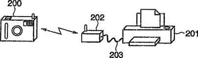
Fig. 1 is the figure of the wired connection example of expression digital camera and printer.As shown in Figure 1, directly connect digital camera 100 and printer 101 by wire cables such as USB 102, when wanting print image data, the user needs to plug wire cable 102 before and after printing.Therefore, in order to alleviate user's complex operations, people are studying the wireless system as cable replacement product (replacement).
At the digital camera that wireless capability is arranged with have and realize between the printer of wireless capability that wireless system is natural, but wish Wireless Telecom Equipment is connected on the existing printer with wired ability simultaneously, make and use the user of existing wired printer also can enjoy wireless service.
But, the action of existing wired printer, for example in patent documentation 1, when connecting in wired mode, the operation program that is connected with digital camera will move automatically.
Therefore, have such problem, that is: when Wireless Telecom Equipment and printer were coupled together, the wireless connections between digital camera that wireless capability is arranged and Wireless Telecom Equipment still imperfect tense, printer can be failed with being connected of digital camera, can not carry out desirable printing.
In addition, connecting about USB, is to connect by USB between Wireless Telecom Equipment and printer, and at this moment, the USB device of Wireless Telecom Equipment is connected with the usb host of printer.Yet the USB device of Wireless Telecom Equipment and personal computer (below be called PC) are connected sometimes, by PC to the communicate by letter information of needed network and fail safe of Wireless Telecom Equipment setting wireless.
That is, have such problem: Wireless Telecom Equipment is that printer or PC change its action according to the communication object that is connected with the USB device of self, therefore, must be applicable to the control of these a plurality of patterns to Wireless Telecom Equipment.
Summary of the invention
The objective of the invention is to, according to the device that is connected with communication interface, control is communicated by letter with this device.
The present invention also aims to, the user does not carry out complicated operations, and communicator that just can be different with communication interface connects and communicates.
In order to achieve the above object, according to one embodiment of the present invention, a kind of communicator with a plurality of communication interfaces is provided, comprise: choice device, according to data, optionally suppress to receive and be used for the communication information that is connected with network via the 2nd communication interface with the communication of the 1st communicator or from above-mentioned the 1st communicator from the 1st communicator that is connected with the 1st communication interface; Be connected with above-mentioned network via the 2nd communication interface based on the above-mentioned above-mentioned communication information that receives, via the communicating devices of this network foundation with the 2nd communicator; Set up with the communicating by letter of above-mentioned the 2nd communicator after, remove device with the inhibition of communicating by letter of above-mentioned the 1st communicator; And, the data communication between above-mentioned the 1st communicator and above-mentioned the 2nd communicator is carried out the device of relaying by above-mentioned the 1st communication interface and above-mentioned the 2nd communication interface.
In addition,, provide a kind of communicator, comprising with a plurality of communication interfaces according to another embodiment of the invention: restraining device, according to the data from the 1st communicator that is connected with the 1st communication interface, inhibition is communicated by letter with the 1st communicator; Set up communicating devices by the 2nd communication interface and the 2nd communicator; Set up with the communicating by letter of above-mentioned the 2nd communicator after, remove device with the inhibition of communicating by letter of above-mentioned the 1st communicator; Identification is by the device of the communications status of above-mentioned the 2nd communication interface and above-mentioned the 2nd communicator; And not under the state of communicating by letter at above-mentioned communications status, when having connected the 3rd communicator by the 3rd communication interface, communicator on the network that forms by above-mentioned the 2nd communication interface, report the device that the service based on above-mentioned the 2nd communication interface has stopped, wherein, when suppressing and the communicating by letter and above-mentioned the 2nd communication interface during of above-mentioned the 1st communicator with above-mentioned the 2nd communication, connected above-mentioned the 3rd communicator on above-mentioned the 3rd communication interface even identify, with do not make before communicating by letter of above-mentioned the 2nd communicator finished above-mentioned the 3rd communication interface for effectively yet.
In addition,, provide a kind of communicator, comprising with a plurality of communication interfaces according to one embodiment of the present invention: restraining device, according to the data from the 1st communicator that is connected with the 1st communication interface, inhibition is communicated by letter with the 1st communicator; Set up communicating devices by the 2nd communication interface and the 2nd communicator; Set up with the communicating by letter of above-mentioned the 2nd communicator after, remove device with the inhibition of communicating by letter of above-mentioned the 1st communicator; Identification is by the device of the communications status of above-mentioned the 2nd communication interface and above-mentioned the 2nd communicator; And be not under the state of communicating by letter at above-mentioned communications status, when having connected the 3rd communicator, become the device of busy condition based on the service of above-mentioned the 2nd communication interface to above-mentioned the 2nd communicator notice by above-mentioned the 2nd communication interface by the 3rd communication interface.
In addition, according to one embodiment of the present invention, a kind of communication means with communicator of a plurality of communication interfaces is provided, comprise: select step, according to data, optionally suppress to receive and be used for the communication information that is connected with network via the 2nd communication interface with the communication of the 1st communicator or from above-mentioned the 1st communicator from the 1st communicator that is connected with the 1st communication interface; Be connected with above-mentioned network via the 2nd communication interface based on the above-mentioned above-mentioned communication information that receives, via the step of communicating by letter of this network foundation with the 2nd communicator; Set up with the communicating by letter of above-mentioned the 2nd communicator after, remove step with the inhibition of communicating by letter of above-mentioned the 1st communicator; And by above-mentioned the 1st communication interface and above-mentioned the 2nd communication interface, the step of between above-mentioned the 1st communicator and above-mentioned the 2nd communicator, carrying out data communication.
Other purpose of the present invention will obtain clearly by following accompanying drawing and detailed description described later.
Description of drawings
Fig. 1 is the figure of the wired connection example of expression digital camera and printer.
Fig. 2 is the figure of the connected mode example of the expression digital camera of embodiment 1 and printer.
Fig. 3 is the figure of the connected mode example of expression and personal computer.
Fig. 4 is the block diagram of an example of structure of the wireless adapter (adapter) of expression embodiment 1.
Fig. 5 is illustrated in USB device one side to use the reset figure of an example of structure of (bus reset) of the usb bus of data signal line.
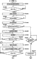
Fig. 6 A, Fig. 6 B are the flow charts of connection control and treatment of the wireless adapter of expression embodiment 1.
Fig. 7 is figure expression embodiment 1, the program when digital camera 200 and printer 201 print wirelessly via wireless adapter 202.
Fig. 8 is the figure of the connected mode example of the expression digital camera of embodiment 2 and printer.
Fig. 9 A, Fig. 9 B are the flow charts of inhibition control and treatment of the wireless adapter of expression embodiment 2.
Figure 10 A, Figure 10 B are the flow charts of connection control and treatment of the wireless adapter of expression embodiment 3.
Figure 11 A, Figure 11 B are the flow charts of inhibition control and treatment of the wireless adapter of expression embodiment 4.
Embodiment
Below, describe the preferred embodiment that is used to carry out an invention in detail with reference to accompanying drawing.
<embodiment 1 〉
Fig. 2 is the figure of the connected mode example of the expression digital camera of embodiment 1 and printer.In Fig. 2, the 200th, have the digital camera of wireless capability, WLAN (wireless local area network)) or Bluetooth (registered trade mark) radio communication functions such as (bluetooths) having with IEEE802.11b/11g/11a etc. is WLAN (the Wireless Local AreaNetwork: of representative.The 201st, the printer that existing support wired (USB cable) connects.The 202nd, the Wireless Telecom Equipment of embodiment 1 is the wireless adapter with a plurality of communication interfaces such as USB, WLAN.Wireless adapter 202 is connected with printer 201 by USB cable 203, and, communicate by WLAN and digital camera 200.And, will send to printer 201 from the view data that digital camera 200 sends via USB cable 203.
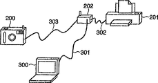
As shown in Figure 3, this wireless adapter 202 by USB cable 301 when being connected with personal computer (PC) 300, carries out from PC300 to the wireless adapter setting of 202 wireless messages.In addition, when being connected with printer 201, as the radio communication repeater of printing usefulness by USB cable 302.And then, when being connected with digital camera 200, be used for carrying out the pairing (pairing) that wireless messages is set with digital camera 200 by USB cable 303.
Then, has the structure of the wireless adapter 202 of above-mentioned a plurality of pattern and a plurality of communication interfaces with Fig. 4 explanation.
Fig. 4 is the block diagram of an example of structure of the wireless adapter 202 of expression embodiment 1.In Fig. 4, the 401st, CPU, the 402nd, RAM, the 403rd, ROM.The 404th, power control unit, the 405th, USB device controller (USB-Device-Ctr), the 406th, USB master controller (USB-Host-Ctr), the 407th, radio-cell.The 408th, the internal bus of wireless adapter 202.
The 409th, USB device (USB-Device) connector, the 410th, USB master (USB-Host) connector, the 411st, detect the signal (Vbus) that whether has connected USB device.The 412nd, be used for the control signal that CPU401 controls power control unit 404.413,414,415 is respectively to use power supply by USB master controller 406 usefulness power supplys, radio-cell 407 usefulness power supplys, the USB device controller 405 of power control unit 404 controls.
And, the 416th, the display that constitutes by LCD, LED etc. of the connection status of display radio adapter 202 etc.
Fig. 5 is illustrated in the figure that USB device one side is used an example of the structure that the usb bus of data signal line resets.In Fig. 5, the 501, the 502nd, usb data holding wire, the 503, the 504th, pull-up resistor (pull up resistance), the 505, the 506th, the switch that is connected of control pull-up resistor and data signal line.And, when carrying out the transmission reception of data, connect pull-up resistor 503,504 by switch 505,506 according to communication speed, thereby the transmission of beginning data receives with the USB device that is connected in USB device connector 409.
When then, using the USB device connector 409 that Fig. 6 A, Fig. 6 B explanation will be connected to wireless adapter 202 as the PC300 or the printer 201 of miscellaneous equipment by USB cable, the performed connections control of CPU 401.
At this moment, wait for that reception is a timer 1 from the timer of the data of the equipment that is connected.Waiting timer 1 timing is full, enters next and handles, thereby formerly set up on the connection basis of WLAN, makes the communication of printer effective once more, and printer can carry out radio communication via wireless adapter and digital camera.
Timer when in addition, carrying out confirming being connected of digital camera and wireless adapter is a timer 2.If the timer 2 that starts timing is full, when promptly not having digital camera, or when not connecting, wireless adapter 202 can be by shifting to CPU park mode (sleepmode), nextly moves with low power consumption.
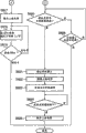
Fig. 6 A, Fig. 6 B are the flow charts of connection control and treatment of the wireless adapter of expression embodiment 1.At first, when connecting the power supply of wireless adapter 202, enter step S601, carry out the initialization of wireless adapter 202.Then, in step S602, judge on USB device connector 409, whether to have connected miscellaneous equipment by signal (Vbus) 411.At this, when signal 411 becomes " high level ", be identified as and connected miscellaneous equipment, enter step S603.In step S603, can carry out the data transfer rate that data transmit according to expression, connect pull-up resistor 503,504 by switch 505,506, become the state that transmits data between permission and the connection device.Then, in step S604, start timer 1, timer 1 was used to measure to the time of identifying till the connecting object.
Then, in step S605, wait for the inquiry that receives from the USB type of the equipment that is connected with USB device connector 409, enter step S606 after the reception, the response of return type.Follow-up processing is the data that affirmation is sent from the equipment that is connected, and confirms the kind (judging it is printer or PC in embodiment 1) and the method for attachment of equipment.
At first, in step S607, are pairing signals that the expression wireless messages is set if for example receive data, then be identified as and be based on being connected of PC shown in Figure 3 300 and USB cable 301, enter step S608, transfer to pairing mode.Then, in step S609, the pairing between wireless adapter 202 execution and the PC 300.In the pairing process, transmit wireless messages from PC 300 to wireless adapter 202, afterwards, wireless adapter 202 forms wireless network according to the wireless messages that is transmitted.
Then, in step S610, judge whether to have finished pairing, when finishing, enter step S617, by switch 505,506 pull-up resistor 503,504 is disconnected in order not allow transmitting and receiving data.Then, in step S618, enter CPU park mode dormancy preset time (n second), in step S619, pulled out for the USB cable 301 of confirming to connect PC 300 and wireless adapter 202 and carry out the judgement of signal 411.Afterwards, when being pulled out, finish this processing from the USB cable 301 of PC 300.
In addition, in above-mentioned steps S607, if, then enter step S611 from the data of the equipment that is connected with USB device connector 409 no pairing signal.In step S611, judge whether to have received other signal, if do not receive any signal then enter step S612,, continue the reception of waiting signal, till timer 1 timing is full if timer 1 does not have timing completely then return step S607.Afterwards, if completely also do not receive pairing signal and other signal, then enter the step S614 that describes in detail later up to timer 1 timing.
In addition, in step S611, when receiving other signal, enter step S613, confirm promptly whether the equipment that is connected is printer 201 from the signal of predetermined printer.At this, when not being signal from printer 201, enter step S617, carry out above-mentioned processing.
On the other hand, when the signal that receives from printer 201, enter step S614, for do not allow and printer 201 between transmitting and receiving data, by switch 505,506 pull-up resistor 503,504 is disconnected.Then, in step S615, beginning is carried out the connection of WLAN by radio-cell 407, and in step S616, startup is used to confirm by the timer that be connected 2 of wireless mode with digital camera 200.
Then, in step S620, carry out the affirmation that is connected with digital camera 200, enter step S621, stop to connect and confirm timer 2 when confirming as when connecting.Then, in step S622, for allow and printer 201 between transmitting and receiving data, connect pull-up resistors 503,504 by switch 505,506.Then, in step S623, owing to begin the action of printer 201 when being connected automatically, therefore, begin between digital camera 200 and printer 201 communication via wireless adapter 202 with digital camera 200.
Then, in step S624, receive print data, confirm whether the communication port that communicates is closed between digital camera 200 and wireless adapter 202.At this, when being closed, communication port enters step S625, and for not allowing data communication, pull-up resistor 503,504 is disconnected by switch 505,506, finish this processing.
In addition, in above-mentioned steps S620, enter step S626 in the time can not confirming as with being connected of digital camera 200, whether timing is full to judge timer 2, proceeds to connect and confirms till timing is full.Afterwards, when timer 2 timing completely still can't be confirmed to connect, enter step S617, carry out above-mentioned processing.
Then, the digital camera 200 of wireless capability is described, via wireless adapter 202 with the mode of radio communication printer 201 transmitted image data files to existing wired ability, and the program when printing by printer 201.
Fig. 7 is figure expression embodiment 1, the program when digital camera 200 and printer 201 print wirelessly via wireless adapter 202.At first, as shown in Figure 2, when wireless adapter 202 is connected with printer 201 by USB cable 203, send type inquiry (701) to wireless adapter 202 from printer 201.Then, when wireless adapter 202 when printer 201 return types responses (702), the PTP that sends expression and the session (session) of digital camera 200 from printer 201 opens session (703).At this, wireless adapter 202 since as yet not and digital camera 200 between set up wireless connections, therefore,, temporarily make above-mentioned pull-up resistor 503,504 disconnect (704) in order not allow and the communicating by letter of printer 201.
Then, wireless adapter 202 beginning WLAN connect, form temporary transient dedicated network (ad hoc network) (705), receiving formation affirmation back (706) from digital camera 200, mode with multileaving (multicast) will add this situation of network, send to the equipment (707) that exists in the consolidated network.At this, digital camera 200 carries out service ability inquiry (708) in order to retrieve the equipment with print service in the mode of multileaving.Thus,, thereby can provide print service to digital camera 200 because wireless communication adapter 202 is present in consolidated network and is connected with printer 201, therefore, to the response (709) of digital camera 200 transmission service ability.
Then, 200 pairs of wireless adapters 202 of digital camera are used to the facility information inquiry (710) of the details of the equipment that obtains.Thus, wireless adapter 202 is to digital camera 200 Returning equipment information responses (711).Then, set up and to be used for the TCP session (712) that digital camera 200 and printer 201 carry out data communication, confirmed the wireless adapter 202 of this foundation,, connect above-mentioned pull-up resistor (713) in order to allow to carry out data communication with printer 201.
Thus, wireless adapter 202 receives the type inquiry (714) from printer 201, transmission types response (715).Current owing to be in the state of setting up wireless link (link) between digital camera 200 and the wireless adapter 202, can carrying out radio communication, therefore, foundation is used for PTP session (716) the transmitted image data file, that become host protocol (host protocol) between printer 201 and digital camera 200.Then, send image data file to printer 201 (717) from digital camera 200 via wireless adapter 202 in the mode of PTP session, after digital camera 200 is finished image data file and is transmitted, the TCP session (718) of end data communication usefulness.
Then, wireless adapter 202 identifications have finished this situation with the radio communication of digital camera 200, and above-mentioned pull-up resistor will be disconnected, and do not allow this advisory printer 201 (719) of transmitting and receiving data.Then, with the equipment that the mode of multileaving continues to exist in consolidated network, send expression and still participate in signal (720) in network.
According to embodiment 1, wireless adapter 202 with a plurality of patterns and a plurality of communication interfaces, when the printer 201 of the digital camera 200 of wireless capability and existing wired ability communicates, control and make and after can carrying out radio communication, make printer 201 action, carry out complicated operations and just can carry out radio communication thereby need not the user with digital camera 200.
In addition, by after connecting the power supply of wireless adapter 202, not carrying out wireless action immediately but control wireless action, thereby seek the reduction of power consumption according to pattern.
<embodiment 2 〉
Then, embodiments of the present invention will be described in detail with reference to the accompanying drawings 2.In embodiment 1, be that example is illustrated with the situation that on the USB device connector 409 of wireless adapter 202, has connected PC 300 or printer 201.In embodiment 2, will be example by the situation that USB cable is connected on the USB main connector 410 with digital camera, the inhibition control of wireless adapter 202 is described.
The structure of the wireless adapter of embodiment 2 is identical with the structure of the embodiment 1 that illustrates with Fig. 4, so omit the explanation to it.
Fig. 8 is the figure of the connected mode example of the expression digital camera of embodiment 2 and printer.As shown in Figure 8, in embodiment 2, on the basis of the connected mode of embodiment shown in Figure 21, also digital camera 800 is connected on the USB main connector 410 of wireless adapter 202 by USB cable 801.Digital camera 800 is to be connected on the wireless adapter 202 for the pairing of carrying out the wireless messages setting.
Then, with Fig. 9 A, Fig. 9 B explanation when wireless adapter 202 identifies oneself with in the network, digital camera 800 is connected under the situation on the USB main connector 410 by USB cable 801, the inhibition control and treatment that CPU 401 is performed.
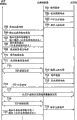
Fig. 9 A, Fig. 9 B are the flow charts of inhibition control and treatment of the wireless adapter of expression embodiment 2.At first, under the state that WLAN has started, begin, in step S901, when the data signal line that detects USB main connector 410 has become high level (High), be judged as and on USB main connector 410, connected equipment (in the present example for digital camera 800).Then, in step S902, judge whether wireless status is to notify this adapter to exist in the mode of multileaving.At this,, then enter step S903 if not notifying if notifying then enter step S904.
In step S903, judge whether wireless adapter 202 carries out radio communication with digital camera 200.At this, when communicating by letter, turn back to step S902, wait for till sign off.Then, when notifying or during sign off, in step S904, the pull-up resistor of the USB device connector 409 that is connected with printer 201 being disconnected, can not carry out data communication.Then, in step S905, send the notice that withdraws from from wireless network with the equipment of mode in being present in consolidated network of multileaving.
Then, in step S906, stop wireless processing, in following step S907, wireless status is set at the free time (IDLE).Then, in step S908, when existence is set pairing request from the wireless messages of the digital camera 800 that is connected with USB main connector 410 by USB cable, enter step S909 and begin pairing.Then, after end is matched in affirmation, enter step S911, when data signal lines are low level after pulling out from the USB cable 801 of digital camera 800, be judged as the connection end, enter step S912, carry out the processing that begins of radio communication from step S910.
Then, when in step S913, forming network, enter step S914, send via the network of this adapter in the mode of multileaving and participate in notice.Then, when in step S915, confirm with being connected of digital camera 200 after, the pull-up resistor of connection USB device in step S916.Then, in step S917, beginning and the communicating by letter of printer 201 when detect sign off in step S918 after, break above-mentioned pull-up resistor at step S919, can not with state that printer 201 is communicated by letter under finish.
According to embodiment 2, the inhibition of communicating by letter according to wireless communication state control printer 201 and wireless adapter 202, thereby in the communication process of wireless adapter 202 and digital camera 200, even receive the request of pairing, also can control and do not hinder the action of carrying out radio communication from other digital camera 800.
<embodiment 3 〉
Then, embodiments of the present invention will be described in detail with reference to the accompanying drawings 3.Embodiment 3 and embodiment 1 is identical substantially, but when wireless adapter 202 is connected with printer 201, and the inhibition when carrying out keeping in inside the request signal from printer 201 is controlled, till the WLAN connection.
The structure of the wireless adapter of embodiment 3 is identical with the structure of the embodiment 1 that illustrates with Fig. 4, so omit the explanation to it.
Then, when on the USB device connector 409 under the connection status shown in Figure 2, at wireless adapter 202, when connecting PC 300 or printer 201 as miscellaneous equipment by USB cable, the performed connection of CPU401 is controlled with Figure 10 A, Figure 10 B explanation.
Figure 10 A, Figure 10 B are the flow charts of connection control and treatment of the wireless adapter of expression embodiment 3.At first, when connect wireless adapter 202 power supply after, enter step S1001, carry out the initialization of wireless adapter 202.Then, in step S1002, judge on USB device connector 409, whether to have connected miscellaneous equipment according to signal (Vbus) 411.At this, when signal 411 becomes " high level ", be identified as and connected miscellaneous equipment, enter step S1003, can transmit the transfer rate of the data of data by switch 505,506 according to expression and connect pull-up resistor 503,504.
Then, in step S1005, wait for the inquiry that receives from the USB type of the equipment that is connected with USB device connector 409, enter step S1006 after the reception, the response of return type.Follow-up processing is the data that affirmation is sent from the equipment that is connected, and confirms the kind (judging it is printer or PC in embodiment 3) and the method for attachment of equipment.
At first, in step S1007, are pairing signals that the expression wireless messages is set if for example receive data, then be identified as and be based on being connected of PC shown in Figure 3 300 and USB cable 301, enter step S1008, transfer to pairing mode.Then, in step S1009, wireless adapter 202 and PC 300 between carry out pairing.In the pairing process, transmit wireless messages from PC 300 to wireless adapter 202, afterwards, wireless adapter 202 forms wireless network according to the wireless messages that is transmitted.
Then, in step S1010, judge whether to have finished pairing, when finishing, enter step S1015, by switch 505,506 pull-up resistor 503,504 is disconnected in order not allow transmitting and receiving data.Then, in step S1016, enter CPU park mode dormancy preset time (n second), in step S1017, in order to confirm to be pulled out and carry out the inspection of signal 411 as the USB cable that is connected 301 of PC 300 and wireless adapter 202.Afterwards, when being pulled out, finish this processing from the USB cable 301 of PC 300.
In addition, in above-mentioned steps S1007,, then enter step S1011, wait for receiving other signal if be not pairing signal from the data of the equipment that is connected with USB device connector 409.Afterwards, enter step S1012 after receiving other signal, keep signal in inside by printer 201 requests.Then, in step S1013, the connection of beginning WLAN, in step S1014, startup is used to confirm by the timer that be connected 2 of wireless mode with digital camera 200.
Then, in step S1018, carry out the affirmation that is connected with digital camera 200, enter step S1019, stop to connect and confirm timer 2 when confirming as when connecting.Then, in step S1021, carry out the reservation of the request signal that kept and remove, and send to printer 201.Then, in step S1022, beginning between digital camera 200 and printer 201 via the communication of wireless adapter 202.
Then, in step S1023, receive print data, confirm whether the communication port that communicates is closed between digital camera 200 and wireless adapter 202.At this, when being closed, communication port enters step S1024, in order not allow data communication, pull-up resistor 503,504 is disconnected by switch 505,506, finish this processing.
In addition, in above-mentioned steps S1018, if can't confirm as and being connected then entering step S1020 of digital camera 200, whether timing has been expired to judge timer 2, proceeds to connect and confirms till timing is full.Afterwards, when timer 2 timing completely still can't be confirmed to connect, enter step S1015, carry out above-mentioned processing.
According to embodiment 3, USB and respond this and reset at printer one side and carry out the such control of processing that begins from communication initialization once more halfway needn't reset.Thus, do not depend on USB especially, can obtain same effect yet and defer to the structure that IEEE1394 etc. for example is connected with wireless adapter.
<embodiment 4 〉
Then, embodiments of the present invention will be described in detail with reference to the accompanying drawings 4.In embodiment 4, identical with embodiment 2, be example with the situation that on USB main connector 410, has connected digital camera by USB cable, the inhibition control of wireless adapter is described.
The structure of the wireless adapter of embodiment 4 is identical with the structure of the embodiment 2 that illustrates with Fig. 4, so omit the explanation to it.
In addition, in embodiment 4,, also use employed connected mode shown in Figure 8 in embodiment 2 as the connected mode of digital camera and printer.
Then, with Figure 11 A, Figure 11 B explanation when wireless adapter 202 identifies oneself with in the network, by USB cable 801 with digital camera 800 is connected under the situation on the USB main connector 410, CPU 401 is performed inhibition control and treatment.
Figure 11 A, Figure 11 B are the flow charts of inhibition control and treatment of the wireless adapter of expression embodiment 4.At first, under the state that WLAN has started, begin, in step S1101, when the data signal line that detects USB main connector 410 has become high level (High), be judged as and on USB main connector 410, connected equipment (in the present example for digital camera 800).Then, in step S1102, confirm to wait for receive the initial state of the timer 1 of pairing request,, make timer 1 begin action if do not begin then enter step S1103.
Then, in step S1104, judge whether wireless state is to notify existing of above-mentioned adapter in the mode of multileaving.At this,, then enter step S1105 if not notifying if notifying then enter step S1106.In step S1105, judge that whether wireless status is for communicating with digital camera 200.At this, when not being is then entering step S1106 when communicating by letter, whether the judgment device state is idle (IDLE).As a result, if the free time then enters step S1107, equipment state is set at busy (BUSY).
In addition, in above-mentioned steps S1105,, make timer 1 stop action, enter step S1109 if wireless status is to communicate by letter with digital camera 200 then enter step S1108.
Then, in step S1109, when from the inquiry request of digital camera 200 receiving equipment information, enter step S1110, equipment state is set at busy, and send the facility information query-response.Then, in step S1111, judge wireless status, turning back to step S1101 when communicating by letter whether for communicating by letter.
Then, in step S1112, judge whether to receive, when receiving, enter step S1114, make timer 1 stop action from the pairing request of digital camera 800 via USB.Then, in step S1115, begin pairing, judge in step S1116 whether timer 2 has begun action.At this,,, make timer 2 begin action and enter step S1118 again if do not begin then enter step S1117 if begun then enter step S1118 same as before.
In the medium end to be paired of this step S1118, if finish then enter step S1119, timing is completely for the timer of end to be paired such as judgements 2.At this, if timer 2 as yet not timing completely then turn back to step S1118 wait end to be paired.If timer 2 timing completely then enter step S1121, message shows on the display 416 of wireless adapter 202 for example " pairing fails to finish, and please pull out cable " by way of caution.This message battery allowance in the pairing process drops to when processing is incomplete below the amount that is enough to handle and shows.
In addition, in above-mentioned steps S1118,,, on the display 416 of wireless adapter 202, for example show " pairing finishes, please pull out cable " as message when pairing enters step S1122 when having finished.Basic messae when this message is the pairing normal termination.
And in above-mentioned steps S1112, when not receiving pairing request as yet, enter step S1113, whether timing is full to judge the timer 1 of waiting for the reception pairing request.At this, if timer 1 not timing completely then turn back to step S1101, if timing is completely then enter into step S1120.Message shows on the display 416 of wireless adapter 202 for example " the PLSCONFM equipment state is pulled out cable " by way of caution.This can think to take place under the situations such as USB main connector 410 that for example will be connected to wireless adapter 202 with the equipment that digital camera 800 has no to concern.
Like this, after any one processing among step S1120~S1122 finishes, enter step S1124, judge that whether wireless status is for notifying.At this, then enter step S1126 same as before if not notifying, if notifying then enter step S1125, the state of equipment is set at idle condition from busy condition, enter step S1126.In this step S1126, pulled out this situation in order to confirm USB cable 801, judge whether the data signal line of USB main connector 410 is low level.Then, when becoming low level, finishes data signal line this processing.
The alert message that shows when pairing finishes also can be under for example urging situation such as enter password, show during the password authentication failure.
In the embodiment of above explanation, when wireless adapter and digital camera are matched, under situation, only suppress to connect control and temporarily do not stop radio communication by other wireless device request pairing.Thus, carry out the digital camera of wireless connections, can adopt polling method (polling) monitored state to change (BUSY → IDLE), thereby can omit the needed time till constructing the wireless network that reconnects, for example the time of " network sweep, identify oneself with in the network, the retrieval of IP address assignment, equipment ", can significantly shorten the time till print next time.
In addition, in the embodiment of above explanation, before receiving pairing request, equipment state is set at BUSY, even now can bring the Digital photographic function that will carry out wireless connections to know the effect of busy (BUSY) state of wireless adapter and printer very soon, but also might be judged as busy (BUSY) when digital camera equipment in addition is connected by USB.
In addition, when after receiving pairing request, equipment state being set at BUSY, can notify BUSY reliably, but owing to judge slack-off, so receive USB pairing request needs considerable times up to state according to the data signal line of USB main connector, at this moment, after with idle (IDLE) response apparatus information query, might allow wireless connections from digital camera.
But, in fact operating this a series of time from the user is substantially near the wrong time, therefore, by timer such among the embodiment 1 is set, also can carry out above-mentioned error detection when digital camera equipment in addition is connected by USB rapidly.
In addition, in embodiment 1~4, as communication, point-to-point (adhoc) pattern with the WLAN of IEEE 802.11x is that example is illustrated, but also the present invention can be used for foundation structure (infrastructure) pattern, Bluetooth (registered trade mark), other communications such as UWB, WiMAX.
The present invention both can be used for the system by a plurality of equipment (for example master computer, interface equipment, reader, printer etc.) formation, also can be used for by 1 equipment constituent apparatus (for example photocopier, picture unit etc.).
In addition, purpose of the present invention can also realize certainly in the following manner, that is: provide the recording medium of the program code of the software of having stored the function that realizes the foregoing description to system or device, the computer of this system or device (CPU or MPU) reads and carries out the program code that is stored in the recording medium.
At this moment, from the program code itself that recording medium reads, realize the function of the foregoing description, the recording medium of having stored this program code constitutes the present invention.
As the recording medium that is used to provide this program code, can use for example floppy (registered trade mark) dish, hard disk, CD, photomagneto disk, CD-ROM, CD-R, tape, non-volatile storage card, ROM etc.
In addition, the program code that reads by object computer is not only arranged, realize the situation of the function of the foregoing description, certainly also comprise following situation, that is: according to the indication of this program code, Yun Hang operating system (OS) etc. is on computers carried out part or all of actual treatment, handle by this, realize the function of the foregoing description.
Certainly also comprise following situation: the program code that will read from recording medium, be written to after the expansion board or the connection memory that functional expansion unit possessed on computers of inserting computer, indication according to this program code, the CPU that this expansion board or functional expansion unit possessed etc. carries out part or all of actual treatment, handle by this, realize the function of the foregoing description.
More than, describe the present invention by preferred embodiment, but the invention is not restricted to the foregoing description, can in the described scope of claim, carry out various distortion.
Claims (10)
1. communicator with a plurality of communication interfaces comprises:
Choice device, according to data, optionally suppress to receive and be used for the communication information that is connected with network via the 2nd communication interface with the communication of the 1st communicator or from above-mentioned the 1st communicator from the 1st communicator that is connected with the 1st communication interface;
Be connected with above-mentioned network via the 2nd communication interface based on the above-mentioned above-mentioned communication information that receives, via the communicating devices of this network foundation with the 2nd communicator;
Set up with the communicating by letter of above-mentioned the 2nd communicator after, remove device with the inhibition of communicating by letter of above-mentioned the 1st communicator; And
By above-mentioned the 1st communication interface and above-mentioned the 2nd communication interface, the data communication between above-mentioned the 1st communicator and above-mentioned the 2nd communicator is carried out the device of relaying.
2. communicator according to claim 1,
Wherein, above-mentioned selected cell is according to the content of the data of sending by above-mentioned the 1st communication interface from above-mentioned the 1st communicator, optionally carries out and suppresses and the communicating by letter or receive the above-mentioned communication information of above-mentioned the 1st communicator.
3. communicator according to claim 1,
Wherein, above-mentioned selected cell is according to the kind of the communicator that connects with above-mentioned the 1st communication interface, optionally carries out and suppresses and the communicating by letter or receive the above-mentioned communication information of above-mentioned the 1st communicator.
4. communicator according to claim 1 also comprises:
Setup unit according to the kind of the 1st communicator that is connected with above-mentioned the 1st communication interface, is set and to be used for the information that is connected with above-mentioned the 2nd communicator.
5. communicator according to claim 4 also comprises:
Transmitting element with the sign off of above-mentioned the 2nd communicator the time, is suppressed and the communicating by letter of above-mentioned the 1st communicator by above-mentioned inhibition unit, sends to represent to identify oneself with signal in the above-mentioned network via above-mentioned the 2nd communication interface.
6. communicator according to claim 1,
In the time can not setting up by communicating by letter outside above-mentioned the 2nd communication interface and above-mentioned the 1st communicator, under the state of communicating by letter that suppresses with above-mentioned the 1st communicator, the control unit of above-mentioned the 2nd communication interface and above-mentioned communicator is moved with low power consumption, and, above-mentioned low power consumption action is down removed in the back at the appointed time, and foundation is by communicating by letter outside above-mentioned the 2nd communication interface and above-mentioned the 1st communicator.
7. communicator with a plurality of communication interfaces comprises:
Restraining device, according to the data from the 1st communicator that is connected with the 1st communication interface, inhibition is communicated by letter with the 1st communicator;
Set up communicating devices by the 2nd communication interface and the 2nd communicator;
Set up with the communicating by letter of above-mentioned the 2nd communicator after, remove device with the inhibition of communicating by letter of above-mentioned the 1st communicator;
Identification is by the device of the communications status of above-mentioned the 2nd communication interface and above-mentioned the 2nd communicator; And
At above-mentioned communications status is not under the state of communicating by letter, when having connected the 3rd communicator by the 3rd communication interface, communicator on the network that forms by above-mentioned the 2nd communication interface is reported the device that the service based on above-mentioned the 2nd communication interface has stopped
Wherein, when suppressing and the communicating by letter and above-mentioned the 2nd communication interface during of above-mentioned the 1st communicator with above-mentioned the 2nd communication, connected above-mentioned the 3rd communicator on above-mentioned the 3rd communication interface even identify, with do not make before communicating by letter of above-mentioned the 2nd communicator finished above-mentioned the 3rd communication interface for effectively yet.
8. communicator with a plurality of communication interfaces comprises:
Restraining device, according to the data from the 1st communicator that is connected with the 1st communication interface, inhibition is communicated by letter with the 1st communicator;
Set up communicating devices by the 2nd communication interface and the 2nd communicator;
Set up with the communicating by letter of above-mentioned the 2nd communicator after, remove device with the inhibition of communicating by letter of above-mentioned the 1st communicator;
Identification is by the device of the communications status of above-mentioned the 2nd communication interface and above-mentioned the 2nd communicator; And
At above-mentioned communications status is not under the state of communicating by letter, and when having connected the 3rd communicator by the 3rd communication interface, becomes the device of busy condition based on the service of above-mentioned the 2nd communication interface to above-mentioned the 2nd communicator notice by above-mentioned the 2nd communication interface.
9. communicator according to claim 1,
Above-mentioned restraining device in order to suppress above-mentioned the 1st communication interface, comprises following any one method: make above-mentioned the 1st communication interface unavailable on hardware; Perhaps return and different response usually, the action of above-mentioned the 1st communicator is stopped for signal by above-mentioned the 1st communicator request; Perhaps keep by of the response of above-mentioned the 1st communicator, do not respond at the appointed time by the signal of above-mentioned the 1st communication interface request.
10. communication means with communicator of a plurality of communication interfaces comprises:
Select step, according to data, optionally suppress to receive and be used for the communication information that is connected with network via the 2nd communication interface with the communication of the 1st communicator or from above-mentioned the 1st communicator from the 1st communicator that is connected with the 1st communication interface;
Be connected with above-mentioned network via the 2nd communication interface based on the above-mentioned above-mentioned communication information that receives, via the step of communicating by letter of this network foundation with the 2nd communicator;
Set up with the communicating by letter of above-mentioned the 2nd communicator after, remove step with the inhibition of communicating by letter of above-mentioned the 1st communicator; And
By above-mentioned the 1st communication interface and above-mentioned the 2nd communication interface, the step of between above-mentioned the 1st communicator and above-mentioned the 2nd communicator, carrying out data communication.
Applications Claiming Priority (2)
| Application Number | Priority Date | Filing Date | Title |
|---|---|---|---|
| JP2005073953A JP4356997B2 (en) | 2005-03-15 | 2005-03-15 | Communication apparatus and communication method thereof |
| JP073953/2005 | 2005-03-15 |
Publications (2)
| Publication Number | Publication Date |
|---|---|
| CN1835539A CN1835539A (en) | 2006-09-20 |
| CN100490489C true CN100490489C (en) | 2009-05-20 |
Family
ID=36498888
Family Applications (1)
| Application Number | Title | Priority Date | Filing Date |
|---|---|---|---|
| CNB2006100648310A Expired - Fee Related CN100490489C (en) | 2005-03-15 | 2006-03-14 | Communication apparatus and method |
Country Status (6)
| Country | Link |
|---|---|
| US (1) | US8037218B2 (en) |
| EP (1) | EP1703411B1 (en) |
| JP (1) | JP4356997B2 (en) |
| KR (1) | KR100815509B1 (en) |
| CN (1) | CN100490489C (en) |
| DE (1) | DE602006016666D1 (en) |
Cited By (1)
| Publication number | Priority date | Publication date | Assignee | Title |
|---|---|---|---|---|
| CN108601010A (en) * | 2018-05-08 | 2018-09-28 | 湖州旭源电气科技有限公司 | The control system of camera wireless blue tooth transfer function can be achieved |
Families Citing this family (28)
| Publication number | Priority date | Publication date | Assignee | Title |
|---|---|---|---|---|
| JP4125173B2 (en) | 2003-04-23 | 2008-07-30 | キヤノン株式会社 | Information processing apparatus connection control method, information processing apparatus, and computer program |
| JP4136771B2 (en) * | 2003-04-23 | 2008-08-20 | キヤノン株式会社 | COMMUNICATION SYSTEM, COMMUNICATION DEVICE, ITS CONTROL METHOD, AND COMPUTER PROGRAM |
| JP4125172B2 (en) | 2003-04-23 | 2008-07-30 | キヤノン株式会社 | Wireless communication system, wireless communication apparatus, control method therefor, and computer program |
| JP4681960B2 (en) * | 2005-06-17 | 2011-05-11 | キヤノン株式会社 | COMMUNICATION DEVICE, COMMUNICATION DEVICE COMMUNICATION METHOD, AND COMPUTER PROGRAM |
| JP4886463B2 (en) | 2006-10-20 | 2012-02-29 | キヤノン株式会社 | Communication parameter setting method, communication apparatus, and management apparatus for managing communication parameters |
| US20080101272A1 (en) * | 2006-10-29 | 2008-05-01 | Sony Ericsson Mobile Communications Ab | Wireless Card and Card Holder for a Digital Camera |
| JP5008387B2 (en) * | 2006-12-06 | 2012-08-22 | キヤノン株式会社 | Wireless communication apparatus and control method thereof |
| US8909296B2 (en) * | 2007-05-14 | 2014-12-09 | Kopin Corporation | Mobile wireless display software platform for controlling other systems and devices |
| EP2150950A1 (en) * | 2007-05-14 | 2010-02-10 | Kopin Corporation | Mobile wireless display for accessing data from a host and method for controlling |
| US9317110B2 (en) * | 2007-05-29 | 2016-04-19 | Cfph, Llc | Game with hand motion control |
| JP2008311950A (en) * | 2007-06-14 | 2008-12-25 | Canon Inc | Wireless communication system, and communication device and control method thereof |
| JP4977543B2 (en) * | 2007-07-20 | 2012-07-18 | 日本電気通信システム株式会社 | Control device, control system, control method, and control program |
| JP4618279B2 (en) * | 2007-08-16 | 2011-01-26 | ソニー株式会社 | Remote control system, receiving device and electronic device |
| US8355671B2 (en) * | 2008-01-04 | 2013-01-15 | Kopin Corporation | Method and apparatus for transporting video signal over Bluetooth wireless interface |
| US9886231B2 (en) | 2008-03-28 | 2018-02-06 | Kopin Corporation | Head worn wireless computer having high-resolution display suitable for use as a mobile internet device |
| JP2010152815A (en) * | 2008-12-26 | 2010-07-08 | Seiko Epson Corp | Information processor, information processing system, and control method of information processor |
| KR101543579B1 (en) * | 2009-02-18 | 2015-08-11 | 삼성전자주식회사 | Power feeding method for a device wired adapter device wired adapter and standalone usb device employing the power feeding method |
| JP2011008311A (en) * | 2009-06-23 | 2011-01-13 | Casio Computer Co Ltd | Input/output control device and electronic musical instrument |
| US20110047384A1 (en) * | 2009-08-21 | 2011-02-24 | Qualcomm Incorporated | Establishing an ad hoc network using face recognition |
| JP5487877B2 (en) * | 2009-10-20 | 2014-05-14 | セイコーエプソン株式会社 | USB device device |
| DE102010042116A1 (en) * | 2010-10-07 | 2012-04-12 | Endress + Hauser Process Solutions Ag | Method for enabling prompt diagnosis, field device connected to a wireless adapter |
| US10009842B2 (en) * | 2011-06-09 | 2018-06-26 | Thomson Licensing | Method for exiting a low-consumption standby mode, and associated device |
| KR102105168B1 (en) * | 2013-05-15 | 2020-04-24 | 삼성전자주식회사 | Display apparatus and control method of the same |
| JP5713078B2 (en) * | 2013-10-08 | 2015-05-07 | 株式会社リコー | Information processing apparatus and information processing system |
| JP6512875B2 (en) * | 2015-03-10 | 2019-05-15 | キヤノン株式会社 | Communication device, control method of communication device, and program |
| JP6683013B2 (en) * | 2016-05-24 | 2020-04-15 | セイコーエプソン株式会社 | Printing apparatus and printing apparatus control method |
| US10445105B2 (en) * | 2018-01-29 | 2019-10-15 | Pixart Imaging Inc. | Scheme for automatically controlling dongle device and/or electronic device to enter waiting state of device pairing in which the dongle device and the electronic device exchange/share pairing information |
| JP2021145159A (en) * | 2020-03-10 | 2021-09-24 | セイコーエプソン株式会社 | Information processing system, communication connection control method of information processing device, communication connection control method of terminal device, and program |
Family Cites Families (90)
| Publication number | Priority date | Publication date | Assignee | Title |
|---|---|---|---|---|
| CH607474A5 (en) | 1976-11-12 | 1978-12-29 | Ibm | |
| KR900006530B1 (en) | 1983-12-30 | 1990-09-07 | 후지쓰가부시끼가이샤 | Method of and apparatus for diagnosing channel control unit |
| JPS60144851A (en) | 1983-12-30 | 1985-07-31 | Fujitsu Ltd | Channel controller |
| KR970010634B1 (en) | 1994-10-25 | 1997-06-28 | 삼성전자 주식회사 | Metwork hibernation system |
| JP2913372B2 (en) | 1994-12-16 | 1999-06-28 | 株式会社コーテックス | Hollow needle for locking piece mounting machine |
| US5699511A (en) | 1995-10-10 | 1997-12-16 | International Business Machines Corporation | System and method for dynamically varying low level file system operation timeout parameters in network systems of variable bandwidth |
| US5754752A (en) | 1996-03-28 | 1998-05-19 | Tandem Computers Incorporated | End-to-end session recovery |
| US5918017A (en) | 1996-08-23 | 1999-06-29 | Internatioinal Business Machines Corp. | System and method for providing dynamically alterable computer clusters for message routing |
| JP3258615B2 (en) | 1996-11-15 | 2002-02-18 | キヤノン株式会社 | Communication system and control method thereof |
| JPH10240551A (en) | 1996-12-26 | 1998-09-11 | Canon Inc | Information processing system and its method |
| JPH10240552A (en) | 1996-12-26 | 1998-09-11 | Canon Inc | Information processor and its method |
| JP3630971B2 (en) | 1997-02-14 | 2005-03-23 | キヤノン株式会社 | Data communication method, apparatus, system, and storage medium |
| JP3880123B2 (en) | 1997-03-12 | 2007-02-14 | キヤノン株式会社 | Data communication device |
| EP0864986B1 (en) | 1997-03-12 | 2006-07-12 | Canon Kabushiki Kaisha | Data communication apparatus, method and system, and program for data communication process stored in memory medium |
| JPH1155298A (en) | 1997-06-06 | 1999-02-26 | Nissan Motor Co Ltd | Information communication equipment |
| JP3045985B2 (en) * | 1997-08-07 | 2000-05-29 | インターナショナル・ビジネス・マシーンズ・コーポレイション | Connection establishment method, communication method, state change transmission method, state change execution method, wireless device, wireless device, and computer |
| JPH11194993A (en) * | 1998-01-06 | 1999-07-21 | Alps Electric Co Ltd | Usb controller |
| JP3671738B2 (en) * | 1999-05-12 | 2005-07-13 | 松下電器産業株式会社 | Transmission management method |
| JPH11239312A (en) | 1998-02-19 | 1999-08-31 | Canon Inc | Control system in direct print digital camera |
| US6912651B1 (en) * | 1998-03-31 | 2005-06-28 | Hewlett-Packard Development Company, L.P. | Wireless universal serial bus link for a computer system |
| US6141719A (en) * | 1998-12-10 | 2000-10-31 | Network Technologies, Inc. | USB selector switch |
| JP2000209238A (en) | 1999-01-14 | 2000-07-28 | Toshiba Corp | Method and apparatus for electronic equipment control |
| US6253268B1 (en) | 1999-01-15 | 2001-06-26 | Telefonaktiebolaget L M Ericsson (Publ) | Method and system for multiplexing a second interface on an I2C interface |
| US20030195983A1 (en) | 1999-05-24 | 2003-10-16 | Krause Michael R. | Network congestion management using aggressive timers |
| JP2001014227A (en) | 1999-06-30 | 2001-01-19 | Nec Corp | Method and device for updating time-out time and machine-readable recording medium with program recorded thereon |
| WO2001048613A2 (en) * | 1999-12-24 | 2001-07-05 | Koninklijke Philips Electronics N.V. | Emulation of a disconnect of a device |
| JP2001273220A (en) | 2000-01-18 | 2001-10-05 | Canon Inc | Device and method for processing information, storage medium and computer program |
| US6697618B1 (en) | 2000-04-19 | 2004-02-24 | Phonex Broadband Corporation | System and method for detecting failures in a wireless phone/modem jack to prevent telephone line seizures |
| JP3669293B2 (en) | 2000-08-04 | 2005-07-06 | ソニー株式会社 | Wireless device mutual authentication system, wireless device mutual authentication method, and wireless device |
| US7207059B1 (en) | 2000-08-16 | 2007-04-17 | Hewlett-Packard Development Company, L.P. | Wireless communication system utilizing antenna dongle |
| FI111312B (en) | 2000-08-25 | 2003-06-30 | Nokia Corp | Monitoring a connection to a user terminal in a telecommunications system |
| GB0028475D0 (en) | 2000-11-22 | 2001-01-10 | Ncr Int Inc | Module |
| AU2002229629A1 (en) | 2000-12-08 | 2002-06-18 | Telefonaktiebolaget Lm Ericsson (Publ) | Method for power save in a mobile terminal |
| US6839344B1 (en) | 2000-12-19 | 2005-01-04 | Nortel Networks Limited | Transport mechanism for ISDN backhaul over IP |
| JP2002202835A (en) | 2000-12-28 | 2002-07-19 | Canon Inc | Electronic equipment and connecting method for electronic equipment |
| US7024482B2 (en) | 2001-02-28 | 2006-04-04 | Sharp Laboratories Of America, Inc. | Pseudo-random dynamic scheduler for scheduling communication periods between electronic devices |
| US7428209B1 (en) | 2001-06-12 | 2008-09-23 | Roberts Lawrence G | Network failure recovery mechanism |
| EP1615385B1 (en) | 2001-06-22 | 2009-03-18 | Panasonic Corporation | Method for carrying out communications among plural stations |
| US7333486B2 (en) | 2001-07-16 | 2008-02-19 | International Business Machines Corporation | Methods and arrangements for monitoring subsource addressing multicast distribution trees |
| US6898652B2 (en) * | 2001-08-22 | 2005-05-24 | General Atomics | Wireless device attachment and detachment system, apparatus and method |
| JP3712369B2 (en) | 2001-09-13 | 2005-11-02 | アライドテレシスホールディングス株式会社 | Media converter and link disconnection method thereof |
| JP3695375B2 (en) | 2001-09-26 | 2005-09-14 | 日本電気株式会社 | Alarm transfer method and method |
| KR100421050B1 (en) | 2001-10-12 | 2004-03-04 | 삼성전자주식회사 | Universal serial bus device having logical circuit for conversive and immediate USB Host reset operation |
| US7058739B2 (en) * | 2001-12-14 | 2006-06-06 | Koninklijke Philips Electronic N.V. | Wireless peripheral interface with universal serial bus port |
| JP2003263253A (en) | 2002-03-07 | 2003-09-19 | Fuji Xerox Co Ltd | Usb device |
| JP2004005541A (en) | 2002-04-16 | 2004-01-08 | Canon Inc | Data transfer device, data transfer method, program and recording medium |
| JP3728276B2 (en) | 2002-06-04 | 2005-12-21 | キヤノン株式会社 | Printing apparatus, control method therefor, and printing system |
| JP2004130784A (en) | 2002-08-22 | 2004-04-30 | Seiko Epson Corp | Printer |
| US7014374B2 (en) | 2002-09-25 | 2006-03-21 | Seiko Epson Corporation | Printing apparatus and printing method for performing pre-communication with an external device |
| JP2004157604A (en) | 2002-11-01 | 2004-06-03 | Matsushita Electric Ind Co Ltd | Usb peripheral control method and device |
| JP2004171158A (en) | 2002-11-18 | 2004-06-17 | Murata Mfg Co Ltd | Usb device |
| US7024501B1 (en) | 2002-11-18 | 2006-04-04 | Cypress Semiconductor Corp. | Method and apparatus for attaching USB peripherals to host ports |
| JP3094734U (en) | 2002-12-17 | 2003-07-04 | 船井電機株式会社 | Printer |
| US7136904B2 (en) | 2002-12-23 | 2006-11-14 | Microtine (San Diego), Inc. | Wireless cable replacement for computer peripherals using a master adapter |
| JP4136771B2 (en) | 2003-04-23 | 2008-08-20 | キヤノン株式会社 | COMMUNICATION SYSTEM, COMMUNICATION DEVICE, ITS CONTROL METHOD, AND COMPUTER PROGRAM |
| JP4125173B2 (en) | 2003-04-23 | 2008-07-30 | キヤノン株式会社 | Information processing apparatus connection control method, information processing apparatus, and computer program |
| JP4125172B2 (en) | 2003-04-23 | 2008-07-30 | キヤノン株式会社 | Wireless communication system, wireless communication apparatus, control method therefor, and computer program |
| US20040223180A1 (en) | 2003-05-08 | 2004-11-11 | Transact Technologies Incorporated | Transactional printer with wireless communication to host |
| US7689223B1 (en) | 2003-06-05 | 2010-03-30 | Sprint Spectrum L.P. | Method and system for delaying retransmission of data traffic to a wireless terminal |
| US20040260745A1 (en) | 2003-06-18 | 2004-12-23 | Gage Christopher A. S. | Load balancer performance using affinity modification |
| JP4323876B2 (en) | 2003-06-20 | 2009-09-02 | キヤノン株式会社 | Data processing apparatus, control method thereof, and control program |
| TWI225200B (en) | 2003-06-24 | 2004-12-11 | Lite On Technology Corp | Fast wake-up wireless signal receiving device |
| US7151949B2 (en) | 2003-07-09 | 2006-12-19 | Lexmark International, Inc. | Wireless facsimile adapter and system for printer and all-in-one devices and methods using the same |
| JP4432385B2 (en) | 2003-07-28 | 2010-03-17 | セイコーエプソン株式会社 | Data relay system |
| JP2005066988A (en) | 2003-08-22 | 2005-03-17 | Canon Inc | Image feeder, recorder, recording system and its controlling method and program |
| US20050048920A1 (en) | 2003-08-26 | 2005-03-03 | Jung-Tao Liu | Method of control signaling in wireless communications |
| US7010638B2 (en) * | 2003-08-29 | 2006-03-07 | Texas Intruments Incorporated | High speed bridge controller adaptable to non-standard device configuration |
| JP3888342B2 (en) | 2003-08-29 | 2007-02-28 | ブラザー工業株式会社 | Network equipment |
| JP4136857B2 (en) | 2003-09-11 | 2008-08-20 | キヤノン株式会社 | Device search method and program |
| US7319867B2 (en) | 2003-09-15 | 2008-01-15 | Atheros Communications, Inc. | Method and apparatus for wake on wireless systems |
| US7631181B2 (en) | 2003-09-22 | 2009-12-08 | Canon Kabushiki Kaisha | Communication apparatus and method, and program for applying security policy |
| US7831282B2 (en) | 2003-10-15 | 2010-11-09 | Eaton Corporation | Wireless node providing improved battery power consumption and system employing the same |
| TWI226551B (en) * | 2003-10-28 | 2005-01-11 | Prolific Technology Inc | Multi-function wireless bridge for USB and associated system |
| US20050197093A1 (en) | 2004-03-05 | 2005-09-08 | Microvision, Inc., A Corporation Of The State Of Delaware | Wireless interface with enhanced functionality |
| US7377441B2 (en) | 2004-03-05 | 2008-05-27 | Microvision, Inc. | Electronic device with auxiliary interfaces |
| JP2005277509A (en) | 2004-03-23 | 2005-10-06 | Canon Inc | Multifunction device and its control method |
| KR20050102824A (en) | 2004-04-23 | 2005-10-27 | 삼성전자주식회사 | Apparatus for usb connection control using usb connetion control button and method the same |
| KR20050119407A (en) | 2004-06-16 | 2005-12-21 | 엘지전자 주식회사 | Method for deleting a session procedure |
| US20050289257A1 (en) | 2004-06-24 | 2005-12-29 | Fink Thomas M | Self-powered USB device with USB power line reset and related USB host and USB system |
| TWM260958U (en) * | 2004-07-23 | 2005-04-01 | Blueexpert Technology Corp | USB wireless transmitter with USB expansion slot |
| KR100612867B1 (en) | 2004-11-02 | 2006-08-14 | 삼성전자주식회사 | Resistive memory device with probe array and manufacturing method the same |
| US8706877B2 (en) | 2004-12-30 | 2014-04-22 | Citrix Systems, Inc. | Systems and methods for providing client-side dynamic redirection to bypass an intermediary |
| US20060253605A1 (en) | 2004-12-30 | 2006-11-09 | Prabakar Sundarrajan | Systems and methods for providing integrated client-side acceleration techniques to access remote applications |
| KR101098576B1 (en) | 2004-12-31 | 2011-12-26 | 주식회사 케이티 | A method for managing session of wireless terminal in a Wireless LAN Service |
| US7657762B2 (en) | 2005-01-14 | 2010-02-02 | Ati Technologies, Inc. | Apparatus and methods for power management of a circuit module |
| JP4656637B2 (en) | 2005-04-27 | 2011-03-23 | キヤノン株式会社 | COMMUNICATION DEVICE, COMMUNICATION SYSTEM AND COMMUNICATION PARAMETER SETTING METHOD |
| JP4900891B2 (en) | 2005-04-27 | 2012-03-21 | キヤノン株式会社 | Communication apparatus and communication method |
| JP4250611B2 (en) | 2005-04-27 | 2009-04-08 | キヤノン株式会社 | Communication device, communication parameter setting method, and communication method |
| JP4266962B2 (en) | 2005-06-16 | 2009-05-27 | キヤノン株式会社 | COMMUNICATION DEVICE, ITS CONTROL METHOD, AND PROGRAM |
| US7746810B2 (en) | 2006-03-31 | 2010-06-29 | Intel Corporation | Wake on wireless network techniques |
-
2005
- 2005-03-15 JP JP2005073953A patent/JP4356997B2/en not_active Expired - Fee Related
-
2006
- 2006-03-14 DE DE602006016666T patent/DE602006016666D1/en active Active
- 2006-03-14 CN CNB2006100648310A patent/CN100490489C/en not_active Expired - Fee Related
- 2006-03-14 EP EP06251338A patent/EP1703411B1/en not_active Not-in-force
- 2006-03-15 KR KR1020060023881A patent/KR100815509B1/en not_active IP Right Cessation
- 2006-03-15 US US11/376,796 patent/US8037218B2/en not_active Expired - Fee Related
Cited By (1)
| Publication number | Priority date | Publication date | Assignee | Title |
|---|---|---|---|---|
| CN108601010A (en) * | 2018-05-08 | 2018-09-28 | 湖州旭源电气科技有限公司 | The control system of camera wireless blue tooth transfer function can be achieved |
Also Published As
| Publication number | Publication date |
|---|---|
| CN1835539A (en) | 2006-09-20 |
| JP4356997B2 (en) | 2009-11-04 |
| EP1703411B1 (en) | 2010-09-08 |
| EP1703411A2 (en) | 2006-09-20 |
| DE602006016666D1 (en) | 2010-10-21 |
| US20060212611A1 (en) | 2006-09-21 |
| EP1703411A3 (en) | 2007-12-05 |
| US8037218B2 (en) | 2011-10-11 |
| JP2006261851A (en) | 2006-09-28 |
| KR100815509B1 (en) | 2008-03-20 |
| KR20060100255A (en) | 2006-09-20 |
Similar Documents
| Publication | Publication Date | Title |
|---|---|---|
| CN100490489C (en) | Communication apparatus and method | |
| JP4502389B2 (en) | COMMUNICATION DEVICE AND ITS CONTROL METHOD | |
| JP4895346B2 (en) | COMMUNICATION DEVICE AND SYSTEM, AND ITS CONTROL METHOD | |
| CN1835441B (en) | Communication apparatus and its control method | |
| JP4794910B2 (en) | System having an electronic device having a plurality of interfaces and a host device, information processing device, electronic device, setup method for the system, control method for the electronic device, setup program, and control program | |
| CN1984220B (en) | Recording system and control method thereof | |
| TWI386805B (en) | Usb sharing switch with automatic switching capabilities | |
| TWI474180B (en) | System and method for detecting remote serial port apparatus | |
| JP5307610B2 (en) | Wireless communication system and communication method | |
| CN103402191B (en) | Communication means, computer-readable recording medium and the wireless connection system of main frame, main frame and equipment | |
| CN101371516A (en) | Communication apparatus and communication layer role deciding method | |
| JP5745424B2 (en) | Device control apparatus, client apparatus, device control method, and device control system | |
| JP4262166B2 (en) | Wireless network system, wireless communication device, and connection setting method | |
| CN102256312B (en) | Communication apparatus and control method thereof | |
| JP2006067373A (en) | Device and method for information processing | |
| JP4363477B2 (en) | Network system | |
| JP2007088726A (en) | Device, and wireless lan setting system and method therefor | |
| JP6452379B2 (en) | COMMUNICATION DEVICE, COMMUNICATION DEVICE CONTROL METHOD, AND COMPUTER PROGRAM | |
| AU2001267838B2 (en) | Image forming device | |
| JP2012053792A (en) | System for reducing usb isochronous transfer error | |
| CN109511102B (en) | Information processing apparatus having a plurality of lines, control method thereof, and storage medium | |
| CN103119914A (en) | Portable terminal and control method of electronic apparatus operation using portable terminal | |
| CN103959889A (en) | Recording medium and control method thereof | |
| JP3212970B2 (en) | USB (Universal Serial Bus) Human Interface Device with Storage Mechanism | |
| JP2007213411A (en) | Bus bridge device |
Legal Events
| Date | Code | Title | Description |
|---|---|---|---|
| C06 | Publication | ||
| PB01 | Publication | ||
| C10 | Entry into substantive examination | ||
| SE01 | Entry into force of request for substantive examination | ||
| C14 | Grant of patent or utility model | ||
| GR01 | Patent grant | ||
| CF01 | Termination of patent right due to non-payment of annual fee |
Granted publication date: 20090520 Termination date: 20160314 |
|
| CF01 | Termination of patent right due to non-payment of annual fee |