JP5307610B2 - Wireless communication system and communication method - Google Patents
Wireless communication system and communication method Download PDFInfo
- Publication number
- JP5307610B2 JP5307610B2 JP2009101380A JP2009101380A JP5307610B2 JP 5307610 B2 JP5307610 B2 JP 5307610B2 JP 2009101380 A JP2009101380 A JP 2009101380A JP 2009101380 A JP2009101380 A JP 2009101380A JP 5307610 B2 JP5307610 B2 JP 5307610B2
- Authority
- JP
- Japan
- Prior art keywords
- network
- wireless device
- host
- printer
- connection request
- Prior art date
- Legal status (The legal status is an assumption and is not a legal conclusion. Google has not performed a legal analysis and makes no representation as to the accuracy of the status listed.)
- Active
Links
Images


Classifications
-
- H—ELECTRICITY
- H04—ELECTRIC COMMUNICATION TECHNIQUE
- H04W—WIRELESS COMMUNICATION NETWORKS
- H04W76/00—Connection management
- H04W76/10—Connection setup
-
- H—ELECTRICITY
- H04—ELECTRIC COMMUNICATION TECHNIQUE
- H04W—WIRELESS COMMUNICATION NETWORKS
- H04W8/00—Network data management
- H04W8/005—Discovery of network devices, e.g. terminals
-
- H—ELECTRICITY
- H04—ELECTRIC COMMUNICATION TECHNIQUE
- H04W—WIRELESS COMMUNICATION NETWORKS
- H04W80/00—Wireless network protocols or protocol adaptations to wireless operation
- H04W80/02—Data link layer protocols
-
- H—ELECTRICITY
- H04—ELECTRIC COMMUNICATION TECHNIQUE
- H04W—WIRELESS COMMUNICATION NETWORKS
- H04W88/00—Devices specially adapted for wireless communication networks, e.g. terminals, base stations or access point devices
- H04W88/02—Terminal devices
- H04W88/06—Terminal devices adapted for operation in multiple networks or having at least two operational modes, e.g. multi-mode terminals
Description
本発明は、ワイヤレスUSBを用いた無線通信システムに関する。 The present invention relates to a wireless communication system using a wireless USB.
近年、Ultra Wide Band(UWB)を用いたワイヤレスUSB(以降「WUSB」)による近距離高速無線通信が開発されている。WUSBは、WiMediaのプロトコルに準拠している。WUSBでは、制御装置であるホストと被制御装置としてのデバイスがある。またWUSBには、ホスト機能とデバイス機能の両方を有するデュアルロールデバイス(以降「DRD」)と、複数のホストに制御されるコンカレントデバイス(Concurrent Device)がある。 In recent years, short-distance high-speed wireless communication using a wireless USB (hereinafter “WUSB”) using an Ultra Wide Band (UWB) has been developed. WUSB conforms to the WiMedia protocol. In WUSB, there are a host as a control device and a device as a controlled device. WUSB includes a dual role device (hereinafter “DRD”) having both a host function and a device function, and a concurrent device controlled by a plurality of hosts.
WUSBは、USBを無線に拡張した技術であるので、有線USBと同様、ホストに接続できるデバイスは複数ある。コンカレントデバイスである無線通信装置は、同時に複数のホストと通信可能であるが、他のデバイスが接続可能なホストは1台のみである。DRDである無線通信装置の場合でも、デバイス機能側では接続可能なホストは1台のみである。 Since WUSB is a technology that expands USB to wireless, there are a plurality of devices that can be connected to a host, like wired USB. A wireless communication apparatus that is a concurrent device can communicate with a plurality of hosts at the same time, but only one host can be connected to other devices. Even in the case of a wireless communication apparatus that is DRD, only one host can be connected on the device function side.
WUSBでは、複数のホストでデバイスを使用するためにはコンカレントデバイスを利用するか、デバイス側でホストを切替えなければならない。また、コンカレントデバイスとして複数のホストと接続可能な機器として動作する場合は、コンカレントデバイスに接続するホストの台数が増大するとコンカレントデバイスの処理負荷が大きくなる。またWUSBでは、ホストがデバイスとの通信で使用する時間をマイクロ・スケジューリング・マネージメント・コマンド(Micro-scheduled Management Command:以降「MMC」)で管理している。従ってコンカレントデバイスに接続するホスト台数が増大すると、ホスト台数分のMMCが占有するため、他通信で利用する時間の確保が困難となる。 In WUSB, in order to use a device with a plurality of hosts, a concurrent device must be used or the host must be switched on the device side. Further, when operating as a device that can be connected to a plurality of hosts as a concurrent device, the processing load on the concurrent device increases as the number of hosts connected to the concurrent device increases. In WUSB, the time used by the host for communication with the device is managed by a micro-scheduled management command (hereinafter referred to as “MMC”). Therefore, when the number of hosts connected to the concurrent device increases, MMCs for the number of hosts occupy, and it becomes difficult to secure time for other communications.
USBでは、コンピュータ(PC)とプリンタ等の周辺機器は、周辺機器がデバイスになり、PCがホストとなって印刷処理等の処理を行う。そのため、WUSBを利用する場合、1つのデバイスを複数のPCで共有するためには、デバイスである周辺機器でホストを切替えるか、周辺機器をコンカレントデバイスにする必要がある。したがって、周辺機器の負荷が大きくなってしまう。 In USB, peripheral devices such as a computer (PC) and a printer perform processing such as print processing with the peripheral device serving as a device and the PC serving as a host. Therefore, when using WUSB, in order to share a single device among a plurality of PCs, it is necessary to switch the host with a peripheral device that is a device, or to make the peripheral device a concurrent device. Therefore, the load on the peripheral device is increased.
本発明は、以上の課題に鑑みてなされたものであり、複数のホストで効率良くデバイスを共用できるようにすることを目的とする。 The present invention has been made in view of the above problems, and an object of the present invention is to allow a plurality of hosts to efficiently share a device.
上記課題を解決するために、ホストおよびデバイスの両方の機能を有する第1および第2無線装置を備える通信システムは、第1無線装置をホストおよび第2無線装置をデバイスとする第1ネットワークを構成し、第1ネットワークを介して第2無線装置から第1無線装置に送信された接続要求に基づき、第1無線装置をデバイスとし、第2無線装置をホストとする第2ネットワークを構成する。
In order to solve the above-described problem, a communication system including first and second radio apparatuses having functions of both a host and a device constitutes a first network having the first radio apparatus as a host and the second radio apparatus as a device. Then, based on the connection request transmitted from the second wireless device to the first wireless device via the first network, the second wireless device is configured with the first wireless device as a device and the second wireless device as a host.
本発明によれば、ユーザー操作による切替え等の複雑な操作を行わないでも、複数のホストで周辺機器等のデバイスを効率良く共用できる。 According to the present invention, devices such as peripheral devices can be efficiently shared by a plurality of hosts without performing complicated operations such as switching by user operations.
<実施形態1>
図1は、実施形態1における無線通信システムの構成例を示す。この無線通信システムの例では、無線通信方式にワイヤレスUSB(WUSB)方式を用いる。図のように、1台の第1無線装置であるプリンタ100と、第1無線装置にとっては外部無線装置となる第2無線装置のパーソナルコンピュータ(PC101)および第3無線装置(PC102)を有する。
<Embodiment 1>
FIG. 1 shows a configuration example of a wireless communication system in the first embodiment. In this example of the wireless communication system, a wireless USB (WUSB) method is used as a wireless communication method. As shown in the figure, the
まずWUSB規格における、ホストおよびデバイスの両方の機能を有するDRDの構成について説明する。図2(a)は、DRD機能の付いたプリンタの内部構成を示す。図2(a)では、説明に必要な機能ブロックだけが示されており、DRD全体が有するその他の機能に関しては省略してある。DRDを有するプリンタ200は、印刷処理部201とDRD機能部202とを有する。DRD機能部202は、ホスト処理部203、デバイス処理部204およびそれらを制御する制御部205を有する。制御部205は、制御プログラムが記憶されたメモリ(不図示)と該制御プログラムを実行するCPUを有する。制御部205は、アンテナ206から受信した高周波信号がホストに関わる信号の場合は、ホスト処理部203へ高周波信号を送り、デバイスに関わる信号の場合は、デバイス処理部204へ高周波信号を送る。ホスト処理部203とデバイス処理部204は、制御部205の制御信号に従い、印刷処理部201とデータ通信を行う。ホスト処理部203は、WUSBにおけるホスト処理およびWiMedia機器としての処理を行う。制御部205は、他のDRDのデバイスからの接続要求コマンドを受信する。もし印刷処理部が使用中でない場合はデバイス処理部204に他のDRDのホストをスキャンし、接続処理を行うように制御する。印刷処理部201は、USBのプリンタクラスを備え、制御部205から受信した印刷データを印刷する。図2(a)に示すように、ホスト処理部203とデバイス処理部204は、機能ごとに独立して構成している。しかし、ホスト処理部203とデバイス処理部204の回路は独立している必要はなく、1つの集積回路内にまとめられても良い。1つの回路にホスト処理部203とデバイス処理部204が集積されている場合は、制御部205は時分割でそれぞれの処理を制御する。また、ホスト処理部203とデバイス処理部204の使用する周波数帯域は、WUSB使用周波数帯域内で同じホッピングパターンであるとする。
First, the configuration of DRD having both host and device functions in the WUSB standard will be described. FIG. 2A shows the internal configuration of a printer with a DRD function. In FIG. 2A, only functional blocks necessary for explanation are shown, and other functions of the entire DRD are omitted. The
図2(b)は、DRD機能を有するパーソナルコンピュータ(PC)における内部構成を示す。DRDコンピュータ300の中で、DRD機能部202内のホスト処理部203、デバイス処理部204と制御部205、およびアンテナ206については、図1で説明したのでその説明を省略する。ここで、図1の構成と異なるコンピュータ301は、演算処理を行い、制御部205とデータ通信を行う。
FIG. 2B shows an internal configuration of a personal computer (PC) having a DRD function. In the
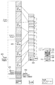
次に、WiMedia通信とWUSB通信について説明する。図3は、WiMediaで定義されるMAC(以降「WiMedia MAC」)のスーパーフレーム(Super frame)の構造およびWUSBのパケット構造を示す。WiMedia MACのスーパーフレーム400は、65.536msの周期で繰り返される。1つのスーパーフレーム400は、265個のMedium Access Slot401(以降「MAS」)で構成される。1個のMASスロットは、256μSの期間を有する。スーパーフレーム400の先頭部分には、様々な制御情報を含むビーコン期間(Beacon Period)402と呼ばれる、ビーコン通信のための期間が設けられている。スーパーフレーム400内にあるビーコン期間402以外のMAS401の部分を用いて、その他のデータ通信が行われる。WUSBは、WiMediaプロトコルの物理層とMAC層を利用し、分散予約プロトコル(Distributed Reservation Protocol:以降「DRP」)方式でデータ通信を行う。分散予約プロトコル方式とは、ビーコンにより予め通知することで、他のデバイスと通信するためのMAS401を予約し、このDRP予約したMASの時間(403)で他のデバイスと通信する方式である。
Next, WiMedia communication and WUSB communication will be described. FIG. 3 shows a super frame structure and a WUSB packet structure of a MAC defined in WiMedia (hereinafter “WiMedia MAC”). The WiMedia MAC
WUSBのホストは、MMC404を用いて、無線通信可能範囲内のWUSBデバイスを管理する。MMC404には、ホスト識別情報、デバイス識別情報、次のMMC404の送信時間指定などが含まれ、次のMMC404の時間を指定することにより連続したデータ通信を行う。WUSBデバイスでは、WiMediaプロトコルの物理層、MAC層に関与せず、MMC404を受信し、必要なデータパケット405だけ受信すれば、ホストとのデータ送信を行うことが可能である。
A WUSB host uses the
WUSBでは、MMC404に続いてデータの中に、まずホストからデバイスへの方向のデータフェーズ(データOUT406)とデバイスからホストへの方向のデータフェーズ(データIN407)がスケジュールされている。またそれに続き、デバイスからのハンドシェーク408のためのスロットもスケジュールされている。MMC404、データOUT406、データIN407およびハンドシェーク408をトランザクショングループと呼ぶ。
In WUSB, following the
ホストへの接続可/不可をデバイスへ通知する方法には、ホストに接続するデバイスすべてに通知する方法と特定のデバイスに通知する方法の2つがある。 There are two methods for notifying a device whether a connection to the host is possible or not: a method for notifying all devices connected to the host and a method for notifying a specific device.
ホストに接続するデバイスすべてに通知する方法は、ホストのMMC404ヘッダ内の予約領域やチャネル情報要素(Channel Information Element)を利用して、ホストに接続するすべてのデバイスに通知するものである。特定のデバイスに通知する方法は、ホストのMMC404ヘッダにおいて接続可/不可の通知を行うデバイスのアドレス409を指定し、そのデバイスに通知するものである。
The method of notifying all devices connected to the host is to notify all devices connected to the host using the reserved area and channel information element in the host's
図4に、ネットワークの構成時の、特定機器への接続可通知とその接続動作およびそのシーケンスを示す。このネットワークは、DRD1_ホスト500をDRD2_デバイス502と接続し、第1ネットワークを構成する第1構成手段を備える。DRD1_ホスト500は、MMC(1)501で通信する対向機器DRD2_デバイス502のアドレス(503)を指定する。DRD1_ホスト500は、DRD1_デバイス504が接続可能である場合に、DRD2_デバイス502に対し、接続可能であることを通知する接続可通知506をデータOUT505により送信する。DRD2_デバイス502は、データIN507のタイムスロットにおいて、第2ネットワークの接続要求508をDRD1_ホスト500に送信する。DRD1_ホスト500は、DRD2_デバイス502側から接続要求508を受信する。そして、第1ネットワークを維持した状態で、DRD1_デバイス504からDRD2_ホスト510への接続を行い、第2ネットワーク511を構成する第2構成手段を備える。構成された第2ネットワーク511経由で、DRD2_ホスト510は、データ512をDRD1_デバイス504に送信する。
FIG. 4 shows a notification of the possibility of connection to a specific device, its connection operation, and its sequence when the network is configured. This network includes first configuration means for connecting the
もしDRD1_デバイス504が接続不可であるならば、データOUT505において、接続不可通知を送信する。図4では、特定機器への接続可通知方法を説明した。ホストに接続するすべてのデバイスに通知する場合は、MMC501において接続可/不可通知を行う。これにより、全てのデバイスに通知される。
If the
図5は、PRNと表示したDRD機能を有するプリンタ600と2台のパーソナルコンピュータPC−A601およびPC−B602との間での動作シーケンスを示す。また図6は、プリンタ600に関する動作フローを示す。また図7には、パーソナルコンピュータPC−A601およびPC−B602に関する動作フローを示す。
FIG. 5 shows an operation sequence between the
図5の動作フローにおける実線矢印は、プリンタがホストとなり、PCがデバイスとなる第1ネットワーク構成における通信を表す。プリンタは、プリンタ内の制御部205によりホスト処理部203を介してホストとしての動作を行う。PCは、PC内の制御部205によりデバイス処理部204を介してデバイスとしての動作を行う。また点線矢印は、PCがホストとなり、プリンタがデバイスである第2ネットワークにおける通信を表す。この場合、プリンタは、プリンタ内の制御部205によりデバイス処理部204を介しデバイスとしての動作を行う。PCは、PC内の制御部205によりホスト処理部203を介してホストとしての動作を行う。更に、動作シーケンスまたは動作フローにおいて記号「H」はホスト、「D」はデバイスを示す。尚、プリンタとプリンタを使用するPCとの間の通信は、既にアソシエーション済と仮定する。
A solid arrow in the operation flow of FIG. 5 represents communication in the first network configuration in which the printer is the host and the PC is the device. The printer operates as a host through the
図5のS603において、プリンタ600を使用するPC−A601とPC−B602は、起動時もしくはプリントジョブ発生時に、デバイスとしてプリンタのホストをスキャンする。S604において、PC−AとPC−Bがプリンタ600を認識可能であれば、デバイスとしてプリンタ600のホストと接続処理を行い、第1ネットワーク構成を行う。また、プリンタ600は接続可能であるとき、第1ネットワーク経由で、定期的に接続可を各PCに通知する。
In S603 of FIG. 5, the PC-
S605において、PC−A601にプリントジョブが発生する。PC−A601は、プリンタが接続可能か否かを確認する。図5では接続可が通知されているので、PC−A601は、プリンタが接続可能を判定する。PC−A601は、プリンタ600が接続可能なので、第1ネットワークを通じ、第2ネットワークの接続要求をプリンタ600に送信する(S606)。
In S605, a print job is generated in the PC-
S607において、第2ネットワークでの接続要求を受信したプリンタ600は、デバイスとして第2ネットワーク経由でPC−A601のホストをスキャンする。S608において、プリンタ600は、PC−A601を認識可能のとき、第2ネットワーク経由でPC−A601のホストに対し接続処理を行い、第2ネットワーク構成を行う。S609において、PC−A601は、第2ネットワークを介して、印刷処理を行う。
In step S <b> 607, the
S610において、第2ネットワークを介してプリンタ600がPC−A601と通信期間中、すなわちプリンタ600の印刷期間中に、プリンタ600は第1ネットワーク経由で定期的に接続不可を通知する。この接続不可通知は、第1ネットワークで報知され、PC−A601、PC−B602が受信することになる。図6のS705とS706でも示されるように、プリンタ600の通信手段は、PC−A601との通信を終了するまで、あるいは印刷を終了するまで印刷不可通知を出力し続ける。S611において、プリンタ600は、PC−A601との通信を終了、または印刷を終了する。
In step S <b> 610, during the communication period of the
S612において、プリンタ600は、PC−A601との第2ネットワークを切断する。プリンタ600は第2ネットワーク切断後、接続可の通知を各PCに通知する。
In step S612, the
S613において、PC−B602にプリントジョブが発生する。S614において、プリンタ600が接続可能であるとき、PC−B602は、第1ネットワークで第2ネットワークの接続要求をプリンタ600に送信する。
In S613, a print job is generated in the PC-
S615において、第2ネットワークの接続要求を受信したプリンタ600はデバイスとしてPC−B602のホストをスキャンする。S616において、PC−B602を認識可能であるとき、接続処理を行い、プリンタ600がデバイス、PC−B602がホストである第2ネットワークを形成する。このプリンタ600のデバイスとPC−B602のホストとのネットワークは、プリンタ600のホストとPC−A601、PC−B602のデバイスとのネットワークを第1ネットワーク、プリンタ600のデバイスとPC−A601のホストとのネットワークを第2ネットワークとすると、第3ネットワークということもできる。S617において、プリンタ600は、形成した第2ネットワーク経由で、PC−B602の通信手段から印刷データを受信し、印刷処理を行う。S618において、プリンタ600は、印刷終了まで、第1ネットワークで接続不可通知を報知する。
In step S615, the
図6には、これまでの動作フローのうち、プリンタ600を主体にした動作フローを示している。S700において、プリンタ600は電源がONとなると動作を開始する。S701において、ホストとして周囲のデバイスであるPC−A601、PC−B602との接続を行い、第1ネットワークを形成する。
FIG. 6 shows an operation flow centered on the
S702において、プリンタ600は接続可能であるとき、第1ネットワーク経由で、定期的に接続可を各PCに通知する。S703において、プリンタ600は、プリントジョブによる接続要求を受信したか否かをチェックする。受信した場合は、S704へ、受信していない場合はS702へ戻る。
In step S702, when the
S704において、プリンタ600は、第2ネットワーク経由で、接続要求を送信した装置(ここでは、PC−A601)のホストをデバイスとしてスキャンする。そして、PC−A601のホストを認識できたならば、デバイスとしてPC−A601のホストへの接続処理を行い、第2ネットワークを構築する。S705において、プリンタ600は、第2ネットワークを介して受信したデータを印刷処理する。また、第1ネットワークでは接続不可通知を報知する。なお、この報知は、第1ネットワークに属するすべてまたは一部のデバイスに行う。
In step S704, the
S706において、プリンタ600は、印刷が終了したか否かをチェックし、完了していない場合は、S705に戻る。印刷が完了すると、S707において、プリンタ600は、PC−A601との第2ネットワークを切断する。S708において、プリンタ600は、電源ががOFFになると、動作を終了する。OFFで無い場合、S702へ戻る。以上が、プリンタ600に関する動作フローである。
In step S <b> 706, the
次に、図5の動作フローのうち、パーソナルコンピュータ(PC−A601、PC−B602)から見た動作フローを図7を用いて説明する。なお、図7の説明では、パーソナルコンピュータをPCとして説明する。
Next, an operation flow viewed from the personal computer (PC-
S800において、PCは電源がONとなると動作を開始する。S801において、デバイスとして周囲のホストをスキャンし、検出したホスト(プリンタ600)と接続を行い、第1ネットワークを形成する。S802において、PCはプリントジョブが発生したことを認識する。 In S800, the PC starts operating when the power is turned on. In step S801, a surrounding host is scanned as a device, and the detected host (printer 600) is connected to form a first network. In step S802, the PC recognizes that a print job has occurred.
S803において、PCは、プリンタ600と接続可能か否かをチェックする。この確認は、プリンタ600は送信している接続可、接続不可の通知を確認することにより行われる。プリンタ600と接続可能な場合、S804において、PCは、第1ネットワークを介して第2ネットワークの接続要求をプリンタ600に送信する。プリンタ600と接続可能でない場合は、チェックを繰り返し接続可能になるまで待つ。
In step S803, the PC checks whether the
S805において、PCは、第2ネットワーク経由でプリンタ600に印刷データを送信し、印刷処理を行う。
In step S805, the PC transmits print data to the
S806において、PCは、は印刷が終了したか否かをチェックする。印刷が終了すると、S807において、電源がOFFになるかをチェックし、OFFになると動作を終了する。OFFで無い場合、S802へ戻る。 In step S806, the PC checks whether printing has ended. When printing is completed, it is checked in step S807 whether the power is turned off. If not OFF, the process returns to S802.
また、図5のS608またはS616において、第2ネットワーク接続を要求したPC−A601またはPC−B602とプリンタ600の接続ができなかった場合は、プリンタ600は、無線出力を調整(送信出力を上げて)して再接続を行う。または、プリンタ600は、第1ネットワーク経由でPCに接続できなかったこと、または通知圏外であることを通知する。あるいは、PCの場所移動を促す通知をする。なお、これらの通知は、PCからプリンタに行ってもよい。また、再接続と通知の両方を行ってもよい。本実施形態を用いることにより、WUSB規格内で、プリンタを複数のPCで効率良く共用可能となる。
If the
<実施形態2>
実施形態1においては、印刷が終了する毎に、ネットワークが切断されていた。実施形態2においては、同じPCで連続して印刷を行う場合は、切断・再接続処理を行わず、ネットワークを保持することで印刷を行うことが可能となる。システム構成、WiMedia規格、WUSB規格および接続可/不可通知・第2ネットワーク接続要求においては実施形態1と同様のため、説明を省略する。
<Embodiment 2>
In the first embodiment, the network is disconnected every time printing is completed. In the second embodiment, when printing is continuously performed on the same PC, it is possible to perform printing by holding the network without performing disconnection / reconnection processing. The system configuration, the WiMedia standard, the WUSB standard, and the connection enable / disable notification / second network connection request are the same as those in the first embodiment, and thus the description thereof is omitted.
実施形態2におけるプリンタ600、PC−A601およびPC−B602の動作シーケンスは、ネットワークの切断シーケンスが異なる点を除けば、図5と同様である。尚、プリンタ600とこのプリンタを使用するPC−A、PC−Bとの間における通信は、既にアソシエーション済と仮定する。
The operation sequence of the
実施形態2では、実施形態1のS611ではPC−A601の印刷終了後に、S612でプリンタ600はPC−A601との第2ネットワーク接続を切断した。しかし、実施形態2では、プリンタはPC−Aの印刷終了後、PC−Aとの第2ネットワークをすぐに切断せず、他のPCから接続要求を受信するまで切断せず保持することを特徴としている。
In the second embodiment, after the printing of the PC-
図8は、実施形態2におけるプリンタの動作フローを示す。S1000において、プリンタ600は動作を開始する。S1001において、プリンタ600はホストとして、周囲のデバイスであるPCと接続し、第1ネットワークを形成する。
FIG. 8 shows an operation flow of the printer according to the second embodiment. In S1000, the
S1002において、プリンタ600は接続可能であるとき、第1ネットワーク経由で、定期的に接続可を周囲のPCに通知する。S1003において、プリンタ600は、プリントジョブによる接続要求を受信したか否かをチェックする。受信した場合は、S1004へ、受信していない場合はS1002へ戻る。
In step S1002, when the
S1004において、プリンタ600は、第2ネットワーク経由で、接続要求を送信した装置(ここでは、PC−A601)のホストをデバイスとしてスキャンする。そして、PC−A601のホストを認識できたならば、デバイスとして、PC−A601のホストへの接続処理を行い、第2ネットワークを構成する。S1005において、プリンタ600は、印刷データを受信するか否かのチェックを行う。受信した場合、S1006に進む。受信しない場合、S1008へ移る。
In step S1004, the
S1006において、プリンタ600は形成した第2ネットワーク経由でPC−A601から受信した印刷データの印刷処理を行う。そして、周りのPCへ接続不可であることを通知する。S1007において、プリンタ600は、印刷が完了したか否かをチェックする。印刷が完了していない場合、S1006へ戻る。印刷が終了したら、S1008へ進む。
In step S1006, the
S1008において、プリンタ600は第1ネットワークを通じ、自身の機器が接続可能であることを第1ネットワークに属するすべてまたは一部のデバイスに通知する。S1009において、プリンタ600は、電源がOFFか否かをチェックする。もしONのままならば、他のPC(PC−B602)からの接続要求か、あるいはPC−A601からの印刷データを受信するかを判定し続ける(S1005、S1010)。そして循環して、S1008の接続可通知を送信し続ける。
In step S1008, the
プリンタ600が接続可能なときに、PC−B602にプリントジョブが発生したとする。PC−B602は、プリンタが接続可能であると判定し、第2ネットワークの接続要求を、第1ネットワーク経由でプリンタ600に送信する。
Assume that a print job is generated in the PC-
プリンタ600は、S1010において第2ネットワークの接続要求を受信すると、S1011において、現在PC−A601と接続している第2ネットワークを切断し、S1004へ戻る。 S1004において、プリンタ600は、第2ネットワークによりデバイスとしてPC−B602のホストをスキャンし、PC−B602を認識できたら第2ネットワーク接続処理を行う。ここでは、プリンタ600がデバイス、PC−Bがホストである第2ネットワークを形成する。
Upon receiving the second network connection request in S1010, the
S1005において、プリンタ600は形成した第2ネットワーク経由でPC−B602から印刷データを受信し、印刷処理を行う。S1006において、プリンタ600は、第1ネットワークを通じ、自身の機器が接続不可であることを第1ネットワークに属するすべてまたは一部のデバイスに通知する。S1007とS1008において、印刷終了後、プリンタはPC−B602との第2ネットワークの切断を行わず、第1ネットワークを通じ、自身の機器が接続可能であることを第1ネットワークに属するすべてまたは一部のデバイスに通知する。
In step S1005, the
第2のネットワークの接続ができなかった場合の処理は、実施形態1と同様のため省略する。本実施形態を用いることにより、WUSB規格内で、プリンタを複数のPCで効率良く共用可能となる。さらに同じPCが連続で印刷を行う場合には切断・再接続処理を行わずに印刷を行うことが可能となる。 Since the processing when the second network cannot be connected is the same as that of the first embodiment, the description thereof is omitted. By using this embodiment, a printer can be efficiently shared by a plurality of PCs within the WUSB standard. Furthermore, when the same PC performs printing continuously, it is possible to perform printing without performing disconnection / reconnection processing.
<実施形態3>
実施形態3では、プリンタが印刷処理を実行中に、他のPCから1以上の接続要求があったとき、順番に接続要求を登録する。そして、印刷処理が終わってから、プリンタは、登録された順番に、接続要求のあったPCとネットワークを構築するという特徴を備える。
<Embodiment 3>
In the third embodiment, when one or more connection requests are received from another PC while the printer is executing print processing, the connection requests are registered in order. Then, after the printing process is completed, the printer has a feature of building a network with a PC that has requested connection in the registered order.
システム構成、WiMedia規格、WUSB規格においては実施形態1と同様のため、説明を省略する。それぞれの接続/接続不可シーケンスは、動作シーケンスの通りであり、接続可/不可通知はホストのデータOUTもしくはMMCヘッダのタイムスロット、接続要求はホストのデータINのタイムスロットにおいて送信する。また、第1ネットワーク接続を切断することなく、第2ネットワーク構成の接続を行う。 Since the system configuration, the WiMedia standard, and the WUSB standard are the same as those in the first embodiment, description thereof is omitted. Each connection / connection disable sequence is the same as the operation sequence, the connection enable / disable notification is transmitted in the time slot of the host data OUT or MMC header, and the connection request is transmitted in the time slot of the host data IN. Further, the second network configuration is connected without disconnecting the first network connection.
図9は、実施形態3におけるプリンタ600、PC−A601およびPC−B602の動作シーケンスの例を示す。また、図10は、プリンタ600の動作フローの例を示す。なお、プリンタ600とプリンタ600を使用するPC−A601、PC−B602との間の通信は、既にアソシエーション済であると仮定する。
FIG. 9 shows an example of an operation sequence of the
図9のPC−A601、PC−B602のデバイスとプリンタ600のホストへの接続までの動作シーケンスは、実施形態1の図5のS603、S604の動作シーケンスと同じため説明を省略する。
The operation sequence up to the connection of the PC-
S1104において、PC−A601にプリントジョブが発生する。S1105において、PC−A601は、第1ネットワークを通して第2ネットワークの接続要求をプリンタ600に送信する。S1106において、第2ネットワークの接続要求を受けたプリンタ600は、第2ネットワークが接続可能であれば、第2ネットワークでPC−A601のホストをスキャンする。
In step S1104, a print job is generated in the PC-
S1107において、プリンタ600は、PC−A601を認識可能であるとき、デバイスとして、PC−A601をホストとする第2ネットワークを形成する。S1108において、プリンタ600は、印刷処理を行う。S1109において、第2ネットワークを介してプリンタ600がPC−A601と通信期間中、すなわち印刷期間中に、PC−B602にプリントジョブが発生する。S1110において、PC−B602は、第1ネットワーク経由で第2ネットワークの接続要求をプリンタ600に送信する。
In step S <b> 1107, when the
S1111において、第2ネットワークの接続要求を受信したプリンタ600は、印刷中であるので、第1ネットワーク経由で第2ネットワーク接続不可をPC−B602に通知する。そしてプリンタ600は、PC−B602が該第2ネットワーク接続要求を送信した機器としてリストに登録する。PC−B602は、プリンタ600が印刷終了後に送信する第2ネットワーク接続可通知を受信するまで待機する。
In step S1111, the
S1112において、プリンタ600は印刷処理が終了する。S1113において、プリンタ600は、同じPCからの印刷ジョブは受信していないので、PC−A601との第2ネットワークを切断する。そして、プリンタ600のリストにPC−B602から接続要求があった旨が登録されているので、S1114において、PC−B602に第2ネットワークの接続が可能であることを通知する。PC−B602は、上記通知を受信すると、S1115において、再度、第1ネットワーク経由で第2ネットワークの接続要求をプリンタ600に送信する。
In step S1112, the
S1116において、プリンタ600は、第2ネットワークでデバイスとしてPC−B602のホストをスキャンする。
In step S1116, the
S1117において、プリンタ600は、PC−B602を認識可能なとき、デバイスとして、PC−B602をホストとする第2ネットワークを形成する。S1118において、プリンタ600は、形成した第2ネットワーク経由でPC−B602から印刷データを受信し、印刷処理を行う。
In step S1117, when the
次に、図9の動作シーケンスを、図10を用いて説明する。S1200において、プリンタ600は動作を開始する。S1201において、プリンタ600は、ホストとして周囲のデバイスであるPC−A601、PC−B602との接続を行い、第1ネットワークを形成する。S1202において、プリンタ600は接続可能であるとき、第1ネットワーク経由で、定期的に接続可を各PCに通知する。S1203において、プリンタ600は、プリントジョブによる接続要求を受信したか否かをチェックする。受信した場合は、S1204へ、受信していない場合はS1202へ戻る。
Next, the operation sequence of FIG. 9 will be described with reference to FIG. In step S1200, the
S1204において、プリンタ600は、第2ネットワーク経由で、接続要求を送信した装置(ここでは、PC−A601)のホストをデバイスとしてスキャンし、認識できたならば、デバイスとして、PC−A601のホストへの接続処理を行い、第2ネットワークを構築する。S1205において、プリンタ600は、第2ネットワークを介して受信したデータを印刷処理する。S1206において、プリンタ600は、印刷が終了したか否かを確認する。もし終了していれば、S1209へ進む。終了していなければ、S1207へ進む。
In step S1204, the
S1207において、プリンタ600は、他のPCから接続要求を受信したか否かを確認する。受信した場合は、S1208へ進み、受信しなかった場合は、S1205へ戻る。
In step S1207, the
S1208において、プリンタ600は接続要求を送信した機器(PC−B602)へ接続不可通知を送信する。また、接続要求を送信した機器をリストに登録する。リストへの登録は、既に登録されている機器があれば、最後尾に登録する。
In step S1208, the
S1206において、プリンタ600は、印刷が終了したならば、S1209において、PC−A601との第2ネットワークを切断する。S1210において、プリンタ600は、リストに機器が登録されているか否かをチェックする。登録されている場合は、S1211へ、登録されていない場合はS1217へ進み、電源がOFFされると動作を終了する。OFFされなけば、S1202に戻る。この例では、プリンタ600のリストの先頭にPC−B602が登録されているので、S1210からS1211へ進む。S1211において、プリンタ600は、PC−B602に第1ネットワーク経由で第2ネットワーク接続可の通知を行う。
In step S1206, when printing is completed, the
この例では、PC−B602は、第2ネットワークの接続可の通知を受信し、第1ネットワークを介して、プリンタ600へ接続要求を送信する。プリンタ600は、接続可を通知したリスト先頭機器(PC−B602)から接続要求を受信したら、S1204へ戻り、PC−B602と第2ネットワークを形成し、その機器との印刷処理を行う。もしプリンタ600が、接続可の通知を行ったにもかかわらず、その機器から接続要求を受信しない場合は、S1213へ進む。
In this example, the PC-
S1213において、プリンタ600は、リストに載っていない機器から接続要求があったか否かをチェックする。もし接続要求があった場合、S1214に進み、接続要求のあった機器を登録リストの最後尾へ登録しS1215へ進む。もしなかった場合も、S1215へ進む。
In step S1213, the
S1215において、プリンタ600は、S1213における接続要求を所定の時間待つ。S1215において、所定の時間経過したら、リストの先頭の機器を最後尾に登録し直し、S1211に戻る。
In step S1215, the
本実施形態のPCの動作フローは、図7における動作フローとほぼ同じである。異なるのは、プリンタ600への接続要求を行い、接続不可の応答を受信すると、接続要求の送信を中断し、第1ネットワークを介してプリンタ600からの接続可が送られてくるのを待つ。プリンタ600からの接続可を受信すると、プリンタ600に接続要求を送信し、第2ネットワークを構築する。
The operation flow of the PC of this embodiment is almost the same as the operation flow in FIG. The difference is that when a connection request to the
図9の動作シーケンスは、PC−Aが印刷中に1台の他の機器からの接続要求であったが、3台以上でも同様に、図10のS1208において順次リストしていく。S1216において、「最後尾にする」とあるが、本実施形態はこれに限定されるものでなく、この機器(PC)をリストから削除してもよい。プリンタの接続ができなかった場合の処理は実施形態1と同様のため省略する。 The operation sequence in FIG. 9 is a connection request from one other device during printing by the PC-A. Similarly, three or more devices are sequentially listed in S1208 in FIG. In S1216, “the last” is described, but the present embodiment is not limited to this, and this device (PC) may be deleted from the list. Since the processing when the printer cannot be connected is the same as that of the first embodiment, a description thereof will be omitted.
本実施形態によれば、印刷中であっても接続要求を受けることができ、印刷が終了すると、印刷中に接続要求を送信した機器との印刷処理を優先的に行うことが出来る。また、印刷中に複数の機器からの接続要求を受けることが出来、要求した順に接続して印刷処理を行える。また、印刷中に接続要求を送信した機器に印刷終了後に接続する際に、その機器に接続許可を通知し、その機器から応答があると接続する。つまり、接続を再確認してから接続するので、接続を拒否された機器が他の機器と接続して印刷を終えたにも係らず、その機器に接続する等の無駄な接続を避けることができる。 According to the present embodiment, a connection request can be received even during printing, and when printing is completed, printing processing with a device that has transmitted the connection request during printing can be preferentially performed. In addition, connection requests from a plurality of devices can be received during printing, and connection processing can be performed in the order requested. Also, when connecting to a device that has transmitted a connection request during printing after connection is completed, the device is notified of connection permission, and connected when there is a response from the device. In other words, since the connection is made after reconfirming the connection, it is possible to avoid useless connection such as connection to the device even though the device refused to connect has connected to another device and finished printing. it can.
<実施形態4>
実施形態4は、実施形態3を変形したものである。異なるのは、実施形態3では、印刷終了後第2ネットワークを切断していた。これに対して、実施形態4では、プリンタが印刷処理中に他のPCから接続要求を受信した場合に印刷を終了すると、第2ネットワークを切断する。
<
The fourth embodiment is a modification of the third embodiment. The difference is that in the third embodiment, the second network is disconnected after the printing is completed. In contrast, in the fourth embodiment, when the printer receives a connection request from another PC during the printing process, when the printing is finished, the second network is disconnected.
つまり、実施形態3の図9では、S1112の第2ネットワークにおける印刷(通信)を終了すると、S1113で第2ネットワークが切断されていた。実施形態4では、第2ネットワークでの印刷を終了しても、第2ネットワークを切断せず、プリンタ600は第1ネットワークを介して、第2ネットワークの接続が可能であることを第1ネットワークに属する機器に通知する。そして、プリンタ600は、第1ネットワークを介して第2ネットワークの接続要求を受信すると、接続中の第2ネットワークを切断し、接続を要求してきた機器のホストと第2ネットワークを構成する。
That is, in FIG. 9 of the third embodiment, when the printing (communication) in the second network in S1112 is finished, the second network is disconnected in S1113. In the fourth embodiment, even when printing on the second network is terminated, the second network is not disconnected, and the
本実施形態のプリンタ600の動作フローを図11に示す。S1500において、プリンタ600は動作を開始する。S1501において、プリンタ600は、ホストとして周囲のデバイスであるPC−A601、PC−B602との接続を行い、第1ネットワークを形成する。S1502において、プリンタ600は、第1ネットワーク経由で、定期的に接続可を各PCに通知する。S1503において、プリンタ600は、プリントジョブによる接続要求を受信したか否かをチェックする。受信した場合は、S1504へ、受信していない場合はS1502へ戻る。
An operation flow of the
S1504において、プリンタ600は、第2ネットワーク経由で、接続要求を送信した装置(ここでは、PC−A601)のホストをデバイスとしてスキャンし、認識できたならば、デバイスとして、PC−A601のホストへの接続処理を行い、第2ネットワークを構築する。S1505において、プリンタ600は、印刷データを受信するか否かのチェックを行う。受信した場合、S1506に進む。受信しない場合、S1510へ進む。S1506において、プリンタ600は形成した第2ネットワーク経由でPC−A601から受信した印刷データの印刷処理を行う。S1507において、プリンタ600は、印刷が終了したか否かを確認する。もし終了していれば、S1510へ進む。終了していなければ、S1508へ進む。
In step S <b> 1504, the
S1508において、プリンタ600は、他のPCから接続要求を受信したか否かを確認する。受信した場合は、S1509へ進み、受信しなかった場合は、S1506へ戻る。S1509において、プリンタ600は接続要求を送信した機器(PC−B602)へ接続不可通知を送信する。また、接続要求を送信した機器をリストに登録する。リストへの登録は、既に登録されている機器があれば、最後尾に登録する。S1507において、プリンタ600は、印刷が終了したならば、S1510において、リストに機器が登録されているか否かをチェックする。登録されている場合は、S1515へ、登録されていない場合はS1511へ進み、S1511では電源がOFFされるかを監視する。電源がOFFされると、S1521において、接続中の第1、第2のネットワークを切断して動作を終了する。OFFされなけば、S1512に進む。
S1512では、他のPCからの接続要求が受信したかを判定し、受信しなければ、S1505に戻り、受信した場合は、S1513において、接続中の第2ネットワークを切断する。そして、S1504において、接続要求を送信した機器と接続して、S1505以降の処理を行う。S1510において、リストに機器が登録されている場合は、S1515において、リスト先頭の機器(PC−B602)に第1ネットワーク経由で第2ネットワーク接続可の通知を行う。
In step S1508, the
In S1512, it is determined whether or not a connection request from another PC has been received. If not received, the process returns to S1505. If received, the second network being connected is disconnected in S1513. In step S1504, the device connected to the device that transmitted the connection request is connected, and the processing from step S1505 is performed. In S1510, if a device is registered in the list, in S1515, the device at the head of the list (PC-B 602) is notified that the second network can be connected via the first network.
この例では、PC−B602は、第2ネットワークの接続可の通知を受信し、第1ネットワークを介して、プリンタ600へ接続要求を送信する。S1516において、プリンタ600は、接続可を通知したリスト先頭機器(PC−B602)から接続要求を受信したら、S1513に進み、接続中のPC−A601との第2ネットワークを切断する。そして、S1504において、PC−B602と第2ネットワークを形成し、その機器との印刷処理を行う。もしプリンタ600が、接続可の通知を行ったにもかかわらず、その機器から接続要求を受信しない場合は、S1516からS1517へ進む。
In this example, the PC-
S1517において、プリンタ600は、リストに載っていない機器から接続要求があったか否かをチェックする。もし接続要求があった場合、S1518に進み、接続要求のあった機器を登録リストの最後尾へ登録し、S1519へ進む。もしなかった場合も、S1519へ進む。S1519では、プリンタ600は、S1516における接続要求を所定の時間待つ。所定の時間経過したら、S1520において、リストの先頭の機器を最後尾に登録し直し、S1511に戻る。
In step S1517, the
以上のように、実施形態3の効果に加え、同じPCが連続で印刷を行う場合には切断・再接続処理を行わずに印刷を行うことが可能となる。 As described above, in addition to the effects of the third embodiment, when the same PC performs printing continuously, it is possible to perform printing without performing disconnection / reconnection processing.
<実施形態5>
図12に実施形態5によるプリンタ600およびPC−A601、PC−B602の動作シーケンスを示す。本実施形態では、実施形態1と同様に、印刷(通信)中に、他のPCから接続要求があるとプリンタ600は接続不可(S1606)を送信し、印刷終了後直ちに第2ネットワークを切断する(S1608)。しかし、接続可の旨を送信せず、他のPCからの接続要求を受信して、該他のPCと第2ネットワークを構成する点に相違がある。したがって、プリンタ600は、図6のS702の接続許可の通知を行う点が実施形態1と異なる。また、PCは、プリンタ600から接続不可の通知を受信しても、定期的に接続要求をプリンタ600に送信する(S1604)。そして、プリンタ600が第2ネットワークを切断した後に接続要求を受信すると(1609)、プリンタはそのPCと接続して印刷処理を行うことになる(S1610〜S1612)。
<Embodiment 5>
FIG. 12 shows an operation sequence of the
従って本実施形態の構成によれば、プリンタを複数のPCで共用することが可能となる。 Therefore, according to the configuration of the present embodiment, the printer can be shared by a plurality of PCs.
<実施形態6>
実施形態6は、実施形態5を変形したものである。実施形態5では、印刷終了後、すぐにPC−A601をホストとする第2ネットワークを切断した。しかし、実施形態6では、印刷終了後、すぐにPC−A601をホストとする第2ネットワークをすぐに切断せず、PC−B602からの接続要求を受信後、切断する。これにより、同じPCが連続で印刷を行う場合には切断・再接続処理を行わずに印刷を行うことが可能となる。
<Embodiment 6>
The sixth embodiment is a modification of the fifth embodiment. In the fifth embodiment, the second network having the PC-
なお、上記各実施形態では2台のPCで説明しているが、3台以上のPCでも同様の動作であり、本実施形態は2台に限定したものではない。また、本実施例ではコンピュータ周辺機器としてプリンタを例に説明したが、コンピュータ周辺機器はカードリーダ、ストレージデバイス、スキャナ、スピーカ、プロジェクタなどでも構わず、同様の構成により複数のPCで共用可能である。 In each of the above embodiments, two PCs are described. However, the same operation is performed with three or more PCs, and the present embodiment is not limited to two. In this embodiment, a printer is described as an example of a computer peripheral device. However, the computer peripheral device may be a card reader, a storage device, a scanner, a speaker, a projector, or the like, and can be shared by a plurality of PCs with the same configuration. .
Claims (10)
前記第1無線装置は、前記第1無線装置をホストおよび前記第2無線装置をデバイスとする第1ネットワークを構成し、
前記第1ネットワークを介して前記第2無線装置から前記第1無線装置に送信された接続要求に基づき、前記第1無線装置をデバイスとし、前記第2無線装置をホストとする第2ネットワークを構成する
ことを特徴とする通信システムのネットワーク構成方法。 A network configuration method for a communication system comprising first and second wireless devices having both host and device functions, comprising:
The first radio device constitutes a first network to the first wireless device host and device the second wireless device,
Based on a connection request transmitted from the second wireless device to the first wireless device via the first network, a second network is configured with the first wireless device as a device and the second wireless device as a host. A network configuration method for a communication system.
前記第2ネットワークを介した前記第2無線装置との通信を終了後、前記第2無線装置との前記第2ネットワークを切断し、
前記第2ネットワークの切断後、前記登録した装置をホストとし、前記第1無線装置をデバイスとする第2ネットワークを構成することを特徴とする請求項1に記載の通信システムのネットワーク構成方法。 When the first wireless device receives a connection request for the second network via the first network during a communication period with the second wireless device via the second network, the first wireless device transmits the connection request. And register
After ending communication with the second wireless device via the second network, disconnecting the second network with the second wireless device;
2. The network configuration method for a communication system according to claim 1, wherein after the disconnection of the second network, a second network is configured with the registered apparatus as a host and the first wireless apparatus as a device.
前記第1無線装置をホストおよび前記第2無線装置をデバイスとする第1ネットワークを構成する第1構成手段と、
前記第1ネットワークを介して前記第2無線装置から前記第1無線装置に送信された接続要求に基づき、前記第1無線装置をデバイスとし、前記第2無線装置をホストとする第2ネットワークを構成する第2構成手段と、
を有することを特徴とする通信システム。 A communication system comprising first and second wireless devices having both host and device functions,
A first configuration means for configuring the first network to devices of prior SL first wireless device host and the second wireless device,
Based on a connection request transmitted from the second wireless device to the first wireless device via the first network, a second network is configured with the first wireless device as a device and the second wireless device as a host. Second configuration means to:
A communication system comprising:
前記無線装置をホストとし、他の無線装置をデバイスとする第1ネットワークを構成するホスト手段と、
前記第1ネットワークを介して前記無線装置に接続要求を送信した前記他の無線装置をホストとし、前記無線装置をデバイスとする第2ネットワークを構成するデバイス手段とを有することを特徴とする無線装置。
A wireless device having both host and device functions,
Host means constituting a first network having the wireless device as a host and another wireless device as a device;
A wireless device comprising: a device unit constituting a second network having the other wireless device that has transmitted a connection request to the wireless device via the first network as a host and the wireless device as a device. .
他の無線装置をホストとし、前記無線装置をデバイスとする第1ネットワークを構成するデバイス手段と、
前記第1ネットワークを介して、前記他の無線装置とデバイスとし、前記無線装置をホストとする第2ネットワークの構成を要求する要求手段と、
前記第2ネットワークを構成するホスト手段と、
を有することを特徴とする無線装置。 The continuously line apparatus that have a function of both the host and the device,
A device unit which constitute the first network to a host of other wireless devices, the pre-quinic ray apparatus with the device,
Via the first network, a request unit operable to another wireless device and the device to request the configuration of a second network to a pre-quinic ray device and the host,
Host means constituting the second network;
No line device further comprising a.
Priority Applications (2)
| Application Number | Priority Date | Filing Date | Title |
|---|---|---|---|
| JP2009101380A JP5307610B2 (en) | 2009-04-17 | 2009-04-17 | Wireless communication system and communication method |
| US12/725,774 US20100268801A1 (en) | 2009-04-17 | 2010-03-17 | Wireless apparatus and network configuring method |
Applications Claiming Priority (1)
| Application Number | Priority Date | Filing Date | Title |
|---|---|---|---|
| JP2009101380A JP5307610B2 (en) | 2009-04-17 | 2009-04-17 | Wireless communication system and communication method |
Related Child Applications (1)
| Application Number | Title | Priority Date | Filing Date |
|---|---|---|---|
| JP2013137445A Division JP5480993B2 (en) | 2013-06-28 | 2013-06-28 | COMMUNICATION DEVICE AND ITS CONTROL METHOD |
Publications (3)
| Publication Number | Publication Date |
|---|---|
| JP2010252193A JP2010252193A (en) | 2010-11-04 |
| JP2010252193A5 JP2010252193A5 (en) | 2012-06-07 |
| JP5307610B2 true JP5307610B2 (en) | 2013-10-02 |
Family
ID=42981807
Family Applications (1)
| Application Number | Title | Priority Date | Filing Date |
|---|---|---|---|
| JP2009101380A Active JP5307610B2 (en) | 2009-04-17 | 2009-04-17 | Wireless communication system and communication method |
Country Status (2)
| Country | Link |
|---|---|
| US (1) | US20100268801A1 (en) |
| JP (1) | JP5307610B2 (en) |
Families Citing this family (13)
| Publication number | Priority date | Publication date | Assignee | Title |
|---|---|---|---|---|
| JP2010152815A (en) * | 2008-12-26 | 2010-07-08 | Seiko Epson Corp | Information processor, information processing system, and control method of information processor |
| JP5723218B2 (en) | 2010-07-13 | 2015-05-27 | キヤノン株式会社 | Loop antenna |
| JP5830984B2 (en) * | 2011-07-05 | 2015-12-09 | 富士ゼロックス株式会社 | Return processing apparatus, printing system, and program |
| JP5919729B2 (en) * | 2011-10-27 | 2016-05-18 | セイコーエプソン株式会社 | Peripheral device status monitoring method, device driver and network system |
| US9253260B1 (en) * | 2011-12-28 | 2016-02-02 | Ewc Controls Incorporated | Hybrid zone control system |
| JP6011167B2 (en) | 2012-09-03 | 2016-10-19 | ブラザー工業株式会社 | Communication relay program and communication relay device |
| JP6075010B2 (en) * | 2012-10-31 | 2017-02-08 | ブラザー工業株式会社 | Communication relay program and image processing apparatus |
| JP6167502B2 (en) | 2012-10-31 | 2017-07-26 | ブラザー工業株式会社 | Communication relay program, communication relay apparatus, and image processing apparatus |
| JP6194798B2 (en) | 2014-01-09 | 2017-09-13 | ブラザー工業株式会社 | Communication equipment and printer |
| JP2015185946A (en) | 2014-03-20 | 2015-10-22 | キヤノン株式会社 | antenna device |
| JP6476616B2 (en) * | 2014-07-04 | 2019-03-06 | 富士ゼロックス株式会社 | Communication device, terminal device, and image processing system |
| JP6755145B2 (en) * | 2016-08-10 | 2020-09-16 | キヤノン株式会社 | Communication devices, their control methods and programs, and communication systems |
| CN106529351A (en) * | 2016-12-05 | 2017-03-22 | 陈丹丹 | USB external structure designing method, computer and secure network system with virus defense capability |
Family Cites Families (16)
| Publication number | Priority date | Publication date | Assignee | Title |
|---|---|---|---|---|
| US6032202A (en) * | 1998-01-06 | 2000-02-29 | Sony Corporation Of Japan | Home audio/video network with two level device control |
| US7013339B2 (en) * | 1998-07-06 | 2006-03-14 | Sony Corporation | Method to control a network device in a network comprising several devices |
| KR100677078B1 (en) * | 1999-11-26 | 2007-02-01 | 삼성전자주식회사 | Method for operating personal ad-hoc network between bluetooth-devices |
| US6950855B2 (en) * | 2002-01-18 | 2005-09-27 | International Business Machines Corporation | Master node selection in clustered node configurations |
| US7797333B1 (en) * | 2004-06-11 | 2010-09-14 | Seisint, Inc. | System and method for returning results of a query from one or more slave nodes to one or more master nodes of a database system |
| US20060064730A1 (en) * | 2004-09-17 | 2006-03-23 | Jacob Rael | Configurable entertainment network |
| KR100679023B1 (en) * | 2004-11-03 | 2007-02-05 | 삼성전자주식회사 | Method and apparatus for supporting multiple wireless universal serial bus host in coordinator-based wireless environment |
| US7756942B2 (en) * | 2005-07-21 | 2010-07-13 | Sony Corporation | System and method for establishing master component in multiple home networks |
| US7733802B2 (en) * | 2005-09-15 | 2010-06-08 | Tp Lab, Inc. | Method to dynamically create a virtual network |
| KR100725932B1 (en) * | 2006-05-02 | 2007-06-11 | 삼성전자주식회사 | Method of operating wireless usb apparatus and wireless usb apparatus using the same |
| US7478188B2 (en) * | 2006-06-02 | 2009-01-13 | Hewlett-Packard Development Company, L.P. | System and method for connecting a WUSB device to multiple WUSB hosts |
| KR100765785B1 (en) * | 2006-06-05 | 2007-10-12 | 삼성전자주식회사 | Method and system for connecting between single wireless device and multiple host using wireless usb |
| US8750241B2 (en) * | 2006-12-08 | 2014-06-10 | Sibeam, Inc. | Concurrent association with multiple wireless networks |
| KR100967400B1 (en) * | 2007-12-11 | 2010-07-01 | 한국전자통신연구원 | Wireless USB device apparatus for networking with plurality of wireless USB host and method thereof |
| JP5180636B2 (en) * | 2008-03-14 | 2013-04-10 | キヤノン株式会社 | Communication device and communication control method thereof |
| CN102017537B (en) * | 2008-04-30 | 2014-04-09 | 松下电器产业株式会社 | Device management system |
-
2009
- 2009-04-17 JP JP2009101380A patent/JP5307610B2/en active Active
-
2010
- 2010-03-17 US US12/725,774 patent/US20100268801A1/en not_active Abandoned
Also Published As
| Publication number | Publication date |
|---|---|
| US20100268801A1 (en) | 2010-10-21 |
| JP2010252193A (en) | 2010-11-04 |
Similar Documents
| Publication | Publication Date | Title |
|---|---|---|
| JP5307610B2 (en) | Wireless communication system and communication method | |
| US10015830B2 (en) | Communication apparatus and communication parameter configuration method thereof | |
| CN104081677B (en) | Communication equipment and communication apparatus control method | |
| JP6207651B2 (en) | Information processing apparatus, control method therefor, and program | |
| JP6797674B2 (en) | Communication equipment, control methods, and programs | |
| EP1616408B1 (en) | Method and apparatus to detect processing units in a wireless network | |
| JP6448265B2 (en) | Information processing terminal, print control method, and program. | |
| JP2007258823A (en) | Communication device and control method thereof | |
| JP6141006B2 (en) | Communication device, control method, and program | |
| US20110058220A1 (en) | Communication system, communication apparatus, and communication control method | |
| JP6800647B2 (en) | Communication equipment, control methods, and programs | |
| JP2006254301A (en) | Ip address setting system | |
| EP2713672B1 (en) | Wireless slave devices configuration and communication therewith | |
| JP6389938B2 (en) | Information processing apparatus and program | |
| CN107102826A (en) | Image processing equipment and its control method | |
| CN107277743B (en) | Communication system, communication device, and control method | |
| JP5480993B2 (en) | COMMUNICATION DEVICE AND ITS CONTROL METHOD | |
| CN103959889A (en) | Recording medium and control method thereof | |
| JP5328843B2 (en) | COMMUNICATION DEVICE AND ITS CONTROL METHOD | |
| JP7141437B2 (en) | Communication device, communication method and program | |
| JP2017200018A (en) | Communication device, terminal device, control method, program and communication system | |
| JP5404941B2 (en) | COMMUNICATION DEVICE AND ITS CONTROL METHOD | |
| JP6642965B2 (en) | Image processing system, image processing device, control method, and program | |
| JP2006148487A (en) | Communication device and its control method |
Legal Events
| Date | Code | Title | Description |
|---|---|---|---|
| A521 | Request for written amendment filed |
Free format text: JAPANESE INTERMEDIATE CODE: A523 Effective date: 20120413 |
|
| A621 | Written request for application examination |
Free format text: JAPANESE INTERMEDIATE CODE: A621 Effective date: 20120413 |
|
| A977 | Report on retrieval |
Free format text: JAPANESE INTERMEDIATE CODE: A971007 Effective date: 20130228 |
|
| A131 | Notification of reasons for refusal |
Free format text: JAPANESE INTERMEDIATE CODE: A131 Effective date: 20130304 |
|
| A521 | Request for written amendment filed |
Free format text: JAPANESE INTERMEDIATE CODE: A523 Effective date: 20130502 |
|
| TRDD | Decision of grant or rejection written | ||
| A01 | Written decision to grant a patent or to grant a registration (utility model) |
Free format text: JAPANESE INTERMEDIATE CODE: A01 Effective date: 20130531 |
|
| A61 | First payment of annual fees (during grant procedure) |
Free format text: JAPANESE INTERMEDIATE CODE: A61 Effective date: 20130627 |
|
| R151 | Written notification of patent or utility model registration |
Ref document number: 5307610 Country of ref document: JP Free format text: JAPANESE INTERMEDIATE CODE: R151 |