JP4354209B2 - Bumper structure - Google Patents
Bumper structure Download PDFInfo
- Publication number
- JP4354209B2 JP4354209B2 JP2003120578A JP2003120578A JP4354209B2 JP 4354209 B2 JP4354209 B2 JP 4354209B2 JP 2003120578 A JP2003120578 A JP 2003120578A JP 2003120578 A JP2003120578 A JP 2003120578A JP 4354209 B2 JP4354209 B2 JP 4354209B2
- Authority
- JP
- Japan
- Prior art keywords
- foam
- bumper
- dimension
- bumper beam
- protrusion
- Prior art date
- Legal status (The legal status is an assumption and is not a legal conclusion. Google has not performed a legal analysis and makes no representation as to the accuracy of the status listed.)
- Expired - Fee Related
Links
Images


Classifications
-
- B—PERFORMING OPERATIONS; TRANSPORTING
- B60—VEHICLES IN GENERAL
- B60R—VEHICLES, VEHICLE FITTINGS, OR VEHICLE PARTS, NOT OTHERWISE PROVIDED FOR
- B60R19/00—Wheel guards; Radiator guards, e.g. grilles; Obstruction removers; Fittings damping bouncing force in collisions
- B60R19/02—Bumpers, i.e. impact receiving or absorbing members for protecting vehicles or fending off blows from other vehicles or objects
- B60R19/18—Bumpers, i.e. impact receiving or absorbing members for protecting vehicles or fending off blows from other vehicles or objects characterised by the cross-section; Means within the bumper to absorb impact
-
- H—ELECTRICITY
- H04—ELECTRIC COMMUNICATION TECHNIQUE
- H04M—TELEPHONIC COMMUNICATION
- H04M1/00—Substation equipment, e.g. for use by subscribers
- H04M1/24—Arrangements for testing
-
- B—PERFORMING OPERATIONS; TRANSPORTING
- B60—VEHICLES IN GENERAL
- B60R—VEHICLES, VEHICLE FITTINGS, OR VEHICLE PARTS, NOT OTHERWISE PROVIDED FOR
- B60R21/00—Arrangements or fittings on vehicles for protecting or preventing injuries to occupants or pedestrians in case of accidents or other traffic risks
- B60R21/34—Protecting non-occupants of a vehicle, e.g. pedestrians
-
- B—PERFORMING OPERATIONS; TRANSPORTING
- B60—VEHICLES IN GENERAL
- B60R—VEHICLES, VEHICLE FITTINGS, OR VEHICLE PARTS, NOT OTHERWISE PROVIDED FOR
- B60R19/00—Wheel guards; Radiator guards, e.g. grilles; Obstruction removers; Fittings damping bouncing force in collisions
- B60R19/02—Bumpers, i.e. impact receiving or absorbing members for protecting vehicles or fending off blows from other vehicles or objects
- B60R19/03—Bumpers, i.e. impact receiving or absorbing members for protecting vehicles or fending off blows from other vehicles or objects characterised by material, e.g. composite
-
- B—PERFORMING OPERATIONS; TRANSPORTING
- B60—VEHICLES IN GENERAL
- B60R—VEHICLES, VEHICLE FITTINGS, OR VEHICLE PARTS, NOT OTHERWISE PROVIDED FOR
- B60R19/00—Wheel guards; Radiator guards, e.g. grilles; Obstruction removers; Fittings damping bouncing force in collisions
- B60R19/02—Bumpers, i.e. impact receiving or absorbing members for protecting vehicles or fending off blows from other vehicles or objects
- B60R19/18—Bumpers, i.e. impact receiving or absorbing members for protecting vehicles or fending off blows from other vehicles or objects characterised by the cross-section; Means within the bumper to absorb impact
- B60R2019/1806—Structural beams therefor, e.g. shock-absorbing
-
- B—PERFORMING OPERATIONS; TRANSPORTING
- B60—VEHICLES IN GENERAL
- B60R—VEHICLES, VEHICLE FITTINGS, OR VEHICLE PARTS, NOT OTHERWISE PROVIDED FOR
- B60R19/00—Wheel guards; Radiator guards, e.g. grilles; Obstruction removers; Fittings damping bouncing force in collisions
- B60R19/02—Bumpers, i.e. impact receiving or absorbing members for protecting vehicles or fending off blows from other vehicles or objects
- B60R19/18—Bumpers, i.e. impact receiving or absorbing members for protecting vehicles or fending off blows from other vehicles or objects characterised by the cross-section; Means within the bumper to absorb impact
- B60R2019/186—Additional energy absorbing means supported on bumber beams, e.g. cellular structures or material
- B60R2019/1873—Cellular materials
-
- B—PERFORMING OPERATIONS; TRANSPORTING
- B60—VEHICLES IN GENERAL
- B60R—VEHICLES, VEHICLE FITTINGS, OR VEHICLE PARTS, NOT OTHERWISE PROVIDED FOR
- B60R19/00—Wheel guards; Radiator guards, e.g. grilles; Obstruction removers; Fittings damping bouncing force in collisions
- B60R19/02—Bumpers, i.e. impact receiving or absorbing members for protecting vehicles or fending off blows from other vehicles or objects
- B60R19/18—Bumpers, i.e. impact receiving or absorbing members for protecting vehicles or fending off blows from other vehicles or objects characterised by the cross-section; Means within the bumper to absorb impact
- B60R2019/1886—Bumper fascias and fastening means therefor
Abstract
Description
【0001】
【発明の属する技術分野】
本発明は、自動車等の車両に使用されるバンパー構造に関する。
【0002】
【従来の技術】
自動車のバンパーは、車両が他車両、或いは壁面等と10km/時以下の低速で衝突した際の車体の保護を目的とするものである。また、かかるバンパーのエネルギー吸収材としては、軽量で緩衝性に優れ、繰り返し圧縮にも優れた復元性を有することから合成樹脂発泡体が用いられることが多い。
【0003】
しかし、近年、歩行者との衝突事故の際にも歩行者に甚大な傷害を与えることのない歩行者保護性能が車両に要求されるようになり、フロントバンパー或いは該バンパーのエネルギー吸収材には、歩行者の脚部を保護するという新たな目的が追加されようとしている。また、車体の小型化、軽量化を図ると共に車体デザインの自由度を向上させるために、よりエネルギー吸収効率が高くコンパクトなバンパーが以前より引き続き要求されている。
【0004】
上記の通り、車体の保護を目的とした従来のバンパー構造では、エネルギー吸収材23は、図11に示すように、外装材21とバンパービーム22との間に位置し、車両衝突時の自らの車重を受け止めて衝撃エネルギーを吸収し、且つ繰り返し衝撃を受けても復元することが求められていた。このような理由により、大きな衝撃エネルギーを受けてもエネルギー吸収材の最大歪みが、復元力を維持できるような範囲とする設計が必要となり、その結果、比較的硬質な材料からなる大型のエネルギー吸収材が採用されていた。また、その他の従来バンパー構造としては、車重が一定重量以下の軽い車両、或いは設定衝撃速度が低速に設計されたものの場合には、充分に剛性のあるバンパービームのみを用いてエネルギー吸収材を使用しない構造のものもあった。
一方、歩行者の脚部を保護する性能が求められるバンパーでは、歩行者の脚部と衝突した場合に脚部を柔軟に受け止め、脚部に甚大な傷害を与えないように最大減速度を脚部の許容最大減速度以下に保つ為の比較的軟質な材料からなるエネルギー吸収材が必要となる。
【0005】
このため、従来の車体の保護を目的としたバンパーと、歩行者の脚部の保護を目的としたバンパーとは、異なる物性が必要となり両立は困難であった。
上記の課題を解決するために、車体の小型化、軽量化、車体デザインの自由度を損ねるものではあるが、車両保護を目的とした比較的硬質のエネルギー吸収材の前面に、歩行者脚部の保護を目的とした比較的軟質のエネルギー吸収材を積層した複合エネルギー吸収材を配置したバンパーが考えられる。しかし、そのような構造のバンパーは歩行者脚部の保護を目的とした比較的軟質のエネルギー吸収材の性能維持が困難である。即ち、上記のように歩行者の脚部を保護する目的として比較的軟質な材料がエネルギー吸収材が採用されたバンパーが取り付けられた車両が、他車両、或いは壁面等と衝突した際の衝撃エネルギーが該エネルギー吸収材に加われば、該エネルギー吸収材は、歪み量が復元性を維持できる最大歪みを超えてしまうため、繰り返しこのような衝撃エネルギーが該バンパーに加われば、次第に圧縮残留歪が蓄積されて歩行者脚部を保護する性能も維持できなくなってしまう。
【0006】
以上説明した課題の全てを満足するバンパー芯材は従来存在せず、次に挙げるバンパーが従来技術として存在するのみであった。
【0007】
【特許文献1】
特開平11−208389号公報 [特許請求の範囲]
【特許文献2】
特開平10−81182号公報 [特許請求の範囲]
【0008】
【発明が解決しようとする課題】
本発明は、車体保護と歩行者脚部等保護の性能を兼備したバンパー構造を提供することを課題とする。
【0009】
【課題を解決するための手段】
本発明によれば、以下に示すバンパー構造が提供される。
[1]外装材とバンパービームとの間に合成樹脂弾性発泡体が配置されたバンパー構造において、該発泡体が見掛け密度0.11〜0.025g/cm 3 のポリプロピレン系樹脂発泡粒子成形体であり、該バンパービームの前方面の上部及び/又は下部に段部が設けられ、該発泡体の上下方向寸法は該段部の上下方向の間隔以下であり、該発泡体が該段部が形成する空間内に位置していると共に該発泡体の一部が該バンパービームの前方面から突出して発泡体突出部を形成し、且つ、該突出部が、前方からの衝撃エネルギー吸収時には該エネルギー量に応じて歪み、該段部が形成する空間内に収納されることを特徴とするバンパー構造、[2]該合成樹脂弾性発泡体の先端に、前方からの衝撃エネルギー吸収時に該凹部内に収納されることがない膨出部が設けられていることを特徴とする前記[1]に記載のバンパー構造、[3]該発泡体突出部の前後方向最小寸法L2と該合成樹脂弾性発泡体の前後方向最大寸法L1との比L2/L1が、0.4〜0.9であることを特徴とする前記[1]又は[2]に記載のバンパー構造。
【0010】
【発明の実施の形態】
以下、本発明のバンパー構造の実施形態について図面に基づいて説明する。
【0011】
先ず、本発明のバンパー構造の参考発明となるバンパー構造について説明する。該バンパー構造においては、図1、図2に示すように、外装材1とバンパービーム2との間に合成樹脂弾性発泡体3(以下、単に発泡体3ともいう。)がエネルギー吸収材として配置されている。
尚、図1は、参考発明のバンパー構造の一例を示す縦断面図であり、図2は参考発明のバンパー構造の一例を示す斜視図である。
【0012】
参考発明更に本発明における発泡体3としては、好ましくはJIS K6767−1976により測定される圧縮永久ひずみが20%以下、更に好ましくは18%以下、特に好ましくは15%以下、最も好ましくは10%以下のものが使用される。具体的な発泡体3としては、弾性に優れると共に適度な剛性を有する直鎖状低密度ポリエチレン、架橋低密度ポリエチレン、エチレンとスチレンとの共重合体などからなるポリエチレン系樹脂発泡体、ポリプロピレン単独重合体、プロピレンとその他のオレフィンとの共重合体、プロピレンとスチレンとの共重合体などからなるポリプロピレン系樹脂発泡体等のポリオレフィン系樹脂発泡体の中でも、更に、剛性、耐熱性、耐薬品性に優れることからポリプロピレン系樹脂発泡体が使用される。また、容易に目的の形状に成形可能であることから発泡体3は、発泡粒子成形体であることを要する。特に、特開2002−167460号公報に記載されている有機過酸化物にて表面が改質された無架橋ポリプロピレン系樹脂発泡粒子を型内成形してなる発泡粒子成形体が好ましい。また、合成樹脂弾性発泡体からなる発泡体3に参考発明又は本発明の目的とする作用、効果が達成できる範囲内であればゴム、ばね等、合成樹脂弾性発泡体以外の素材を複合することもできる。
【0013】
参考発明のバンパー構造においては、図1に示すように、バンパービーム2の前方面に凹部4が設けられている。更に、発泡体3は凹部4内に位置していると共に、発泡体3の一部がバンパービーム2の前方面から突出して発泡体突出部5(以下、単に突出部5ともいう。)を形成している。このように、参考発明においては、発泡体3の一部がバンパービーム2の凹部4の中に入り、突出部5(図1の二重斜線で表された部分)がバンパービーム2の前方に出ているので、前後方向寸法が長い発泡体3を用いた場合であっても、バンパー構造としてはバンパーの前後方向寸法を短くすることができる。従って、車体の小型化、軽量化、車体デザインの自由度を損ねることなく車体保護と歩行者脚部保護の性能を兼備することが可能となる。
尚、本明細書において、バンパービームの前方面とは、該バンパービームを有する構造のバンパーが車体に取り付けられた場合、該車体の前側に位置するバンパービームの前側を向いている面である。従って、バンパービームの前方面から突出する突出部5は、バンパーが車体に取り付けられた場合、車体の前方向若しくは略前方向に向かって突出することになる。
【0014】
参考発明においては、凹部4は一つに限定されるものではなく複数設けられてもよい。例えば、二つの凹部が設けられ、二つの発泡体3が各々の凹部内に位置していると共に、発泡体の各々の一部がバンパービーム2の前方面から突出していてもよい。このように、本明細書において単に発泡体3という場合、複数の発泡体からなる場合を含む意味である。尚、参考発明においては、複数の凹部が設けられているにもかかわらず、一つの発泡体3が一の凹部内に位置していると共に、発泡体の一部がバンパービーム2の前方面から突出していてもよい。
【0015】
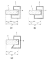
本発明のバンパー構造においては、図14(a)に示すように、バンパービーム2の前方面の上部に段部11aが設けられ、下部に段部11bが設けられている。そして、発泡体3aが段部11aが形成する空間内に位置しており、発泡体3bが段部11bが形成する空間内に位置している。更に、発泡体3a及び発泡体3bの一部がバンパービーム2の前方面から突出して突出部5を形成している。このように構成されていると、車体の小型化、軽量化、車体デザインの自由度を損ねることなく車体保護と歩行者脚部保護の性能を兼備することが可能となる。
但し、段部11は、バンパービーム2の前方面の上部又は下部のどちらかに設けてもよい。図14(b)に、バンパービーム2の前方面の上部に段部11を設けた例を示す。
また、前方面の上部及び下部に段部が設けられているにもかかわらず、一つの発泡体3がどちらかの段部が形成する空間内に位置していると共に、発泡体の一部がバンパービーム2の前方面から突出していてもよい。
【0016】
上記発泡体3の見掛け密度および素材にて定まる剛性、並びに発泡体3の上下方向寸法、前後方向寸法、発泡体突出部の前後方向寸法は、歩行者脚部との衝突の際に発生する衝突エネルギーを歩行者脚部に甚大な傷害を与えない許容最大減速度を超えない範囲内の減速度にて吸収することが可能であると共に、該エネルギー吸収時に発泡体突出部の歪み量が復元力を維持できる最大歪以下の範囲内となるように決定される。但し、発泡体3の上下方向寸法は概ね段部11の上下方向の間隔、又は凹部4の上下方向の間隔以下に、発泡体3の左右方向寸法は概ね外装材1の左右方向の幅以下に制限される。
尚、本明細書において、発泡体突出部の前後方向とは、該発泡体突出部を有する構造のバンパーが車体に取り付けられた場合において、車体の前後方向と一致する方向であり、発泡体3の前後方向と上下方向と左右方向は、各々、該発泡体を有する構造のバンパーが車体に取り付けられた場合の車体の前後方向と一致する方向と車体の上下方向と一致する方向と車体の左右方向と一致する方向である。
【0017】
更に、参考発明又は本発明のバンパー構造においては、突出部5が、前方からの衝撃エネルギー吸収時にはエネルギー量に応じて歪み、凹部4内又は段部11が形成する空間内に収納されるように構成されている。
参考発明又は本発明のバンパー構造において、歩行者脚部と衝突した場合には、発泡体3の突出部5がその衝撃エネルギーを吸収しながら歪み、最大減速度は脚部が許容できる許容最大減速度を超えず、発泡体3の前後方向の歪み量は、該突出部5の前後方向の長さを基本的に超えることがないように設計されるため、該衝突時に設計値を超える衝撃エネルギーが加わらない限り、歩行者脚部が甚大な傷害を受けることがないように保護することが可能となる。
【0018】
また、車両が他車両、或いは壁面等と低速で衝突した場合には、図3に示すように、突出部5はその衝撃エネルギーを吸収しながら歪み、最終的に全ての突出部5は凹部4内に収納されて凹部4内に埋め込まれた状態になり、発泡体3はそれ以上圧縮されることがなくなり、発泡体3と比べて剛性の高いバンパービーム2が他車両、或いは壁面との衝撃エネルギーを受け止めることにより車体は保護される。そして、発泡体3はバンパービーム2に設けられた凹部4の前後方向(該発泡体を有するバンパーが車体に取り付けられた場合の車体の前後方向と一致する方向)の寸法に相当する厚みは残されるため、このような衝撃を受けても、高い復元性を維持することが可能であり、歩行者脚部保護性能を維持することが可能となる。段部11がバンパービームに設けられている場合も、図示はしないが、凹部4が設けられている場合と同様である。
尚、図3は参考発明によって得られるバンパーが壁面24等に衝突した場合の一例を示す縦断面図である。
【0019】
バンパービーム2に設けられた段部11が形成する空間内又は凹部4内に位置している発泡体3は、該段部11又は凹部4に隙間なく挿入されていることが設計効率上好ましいが、必ずしもそのように挿入されていなくても上記の通り衝撃エネルギー吸収時には該エネルギー量に応じて歪み、該凹部4又は段部11内に突出部5が収納され、且つ大きな衝撃エネルギーが加わった場合であっても凹部4又は段部11の前後方向最大寸法(以下、凹部4の深さ又は段部11の深さともいう。)の厚みは略残されるように発泡体3が凹部4内又は段部11が形成する空間内に位置していればよい。
【0020】
また、発泡体3の形状は直方体形状に限らず、先端面を外装材の内面形状に合わせること、先端面に左右方向に亘る凹部を設けること、または発泡体に肉盗み部を設けること等、参考発明又は本発明の目的とする作用、効果が達成できる範囲内であれば如何なる形状も採用できる。
【0021】
参考発明又は本発明のバンパー構造は上記の通り、発泡体3が歩行者脚部との衝突による衝撃エネルギーを吸収し、その際の最大減速度を脚部保護のために必要な許容最大減速度を超えない範囲内とするものであり、他車両との衝突、或いは壁面との衝突による衝撃エネルギーは、発泡体3の突出部5の前後方向最小寸法までの圧縮歪みによるエネルギー吸収と共に、充分な剛性を有するバンパービーム2が受け止めるようにするものである。そして、このことにより本来相反する歩行者脚部保護性能と車両保護性能とを兼備するバンパー構造が実現できる。
【0022】
上記の歩行者脚部との衝突の際の最大減速度を脚部保護のために必要な許容最大減速度を超えない範囲内とするためには、発泡体3の上下方向寸法を小さくして脚部を押圧する部分の面積を小さくすると共に、発泡体3の前後方向寸法を長くすることにより、圧縮荷重を一定の値(許容最大減速度に対応する圧縮荷重の値)以下に維持すればよい。尚、合成樹脂弾性発泡体は、圧縮時に発泡体の圧縮歪み量がある値以上になると圧縮荷重が急激に高まる所謂『底づき現象』がみられる為、発泡体3の前後方向寸法は、『底づき現象』が発生しない範囲にて衝突エネルギーを吸収できる寸法に設定する必要がある。具体的には、発泡体3はポリプロピレン系樹脂発泡粒子成形体からなることから、圧縮歪み量60〜70%を境にそれ以上の圧縮歪み量にて『底づき現象』が発生し、また、圧縮残留歪も大きなものとなり復元性も大きく低下する。
そして、参考発明又は本発明のバンパー構造は、上記のように発泡体3の前後方向寸法を長くしても、発泡体3の一部はバンパービーム凹部4又は段部11が形成する空間に挿入されている為、バンパー構造自体の前後方向寸法は長くなることはなく、前述のように該凹部4又は段部11が形成する空間に発泡体3の一部が位置することにより、大きな衝撃エネルギーが加わったとしても発泡体前後方向寸法の凹部4又は段部11の深さに相当する厚みは略残されるため、発泡体の『底づき現象』も確実に防ぐことができる。よって、参考発明又は本発明のバンパー構造は歩行者脚部保護、車体保護の目的に加えて、小型化も可能であり、バンパーのデザインの自由度も大きなものとなる。
【0023】
また、発泡体3を構成する合成樹脂は、樹脂の曲げ弾性率、引張弾性率を指標にして剛性、柔軟性を考慮し、更に、耐熱性、脆性、発泡適性等も考慮すると、ポリプロピレン系樹脂が選択される。また、発泡体3を構成する見掛け密度を決定するにあたっては、以下の<1>、<2>の要件が重要である。また、発泡体3の上下方向寸法や前後方向寸法を決定するには、以下の<3>〜<6>の要件が重要である。
<1>合成樹脂弾性発泡体は十分に衝撃エネルギー吸収する為に、該発泡体の見掛け密度が低くなる程その体積を大きくしなければならず、従って、突出部の上下方向寸法に最大減速度を小さくする為の制約とバンパービームの凹部又は段部の上下方向寸法の制約がある以上、突出部の前後方向最小寸法L2は長くしなければならなくなる。<2>合成樹脂弾性発泡体の見掛け密度が低くなるほど『底づき現象』が発生しない歪み量範囲での最大減速度が小さくなる。<3>合成樹脂弾性発泡体の上下方向寸法が短くなるほど歩行者脚部との接触面積が狭くなり、『底づき現象』が発生しない歪み量の範囲において衝撃エネルギー吸収時の最大減速度が小さくなる。<4>発泡体3の前後方向寸法が長いほど大きな衝撃エネルギーを吸収できる。<5>歩行者脚部との衝突時、『底づき現象』が発生しない歪み量の範囲で歩行者脚部への衝撃エネルギーを吸収できるようにする。<6>合成樹脂弾性発泡体の種類により差異はあるが、圧縮歪み量が大きいと圧縮残留歪も大きくなる。
【0024】
上記基本原理を踏まえ、参考発明又は本発明のバンパー構造は以下のように設計できる。
参考発明又は本発明のバンパー構造におけるバンパービームは、図1〜図6、図12、図14に示されるように、該バンパービームの前方面に凹部又は段部が設けられており、全体形状、素材、成形方法等は、例えば、特開2001−322517号公報、特開平11−78730号公報に記載の従来公知のものであって、他車両、或いは壁面との衝突時、エネルギー吸収材の歪みによる衝撃エネルギー吸収と併せ、或いはバンパービーム単独で衝撃を受け止めて車体を保護することのできる剛性を有し、更に、参考発明又は本発明のバンパー構造に採用した場合、歩行者脚部との衝突時に発泡体3の前後方向後面が接するバンパービーム凹部又はバンパービーム段部の前後方向底面が、歩行者脚部との衝突による衝撃に耐え得る剛性を有するものが使用できる。
【0025】
従って、参考発明又は本発明のバンパー構造の設計は歩行者脚部保護性能を付加するとういう観点からは発泡体3の設計が重要である。発泡体3の設計は、例えば、歩行者脚部との衝突を想定し、具体的には人体の脚部相当のインパクターが速度40kg/時で衝突した場合において、発生する衝撃エネルギーを吸収し、且つ発生する最大減速度が脚部に甚大な傷害を与えない許容最大減速度以下となることを目的に行う。但し、脚部との衝突による衝撃エネルギーは、発泡体3だけではなく外装材1、バンパービーム2、足首部分が衝突するフロントスカート部等によっても吸収されるため、車両毎に発泡体3が吸収しなければならないエネルギー量は相違する。
【0026】
更に参考発明又は本発明のバンパー構造の具体的な設計としては、前述の発泡体3の設計目的に従い、発泡体3としてポリプロピレン発泡粒子成形体を使用することから、『底づき現象』によって圧縮荷重は歪み量60〜70%を境に該歪み量以上では急激に上昇する。従って、発泡体3の前後方向最大寸法L1の内、30〜40%の長さの部分がバンパービーム2の凹部4又は段部11が形成する空間に収納されるように設計することにより、衝突時に発泡体3が前後方向に圧縮されることによって発生する圧縮荷重が、該発泡体3の突出部5が完全に該凹部4内又は段部11が形成する空間内に収納されるまでは、急激に上昇することはなく発泡体3の突出部5の前後方向最小寸法L2の全てを有効なストロークとして利用できる。このため、バンパーのデザインに制約を与えるバンパービームの前方に確保すべき発泡体の前後方向最大寸法を必要な分だけ長くしても、参考発明又は本発明のバンパー構造では該凹部4又は段部11を有効に利用することにより、バンパー自体の前後方向寸法は長くなることはない。
【0027】
また、複数回の衝突を考慮してL2を割り増しする等して衝撃エネルギー吸収性能を高めに設定することが更に好ましい。その衝撃エネルギー吸収性能をどの程度高めるかは、実際に衝突試験を行い安全率を見て決定する。
尚、上記設計手順は例示であって、その他の手順にて参考発明又は本発明のバンパー構造を設計することもできる。
【0028】
上記の通り、突出部5の前後方向最小寸法L2を要求される衝撃エネルギーの設計値に対応して定め、該L2と発泡体3の前後方向最大寸法L1との比L2/L1を、発泡体3が弾性回復できる範囲内に定めておけば、発泡体3は他車両、或いは壁面等に衝突した後であっても、元の形状、寸法に回復する復元性は大きく低下することがない。
【0029】
上記比L2/L1は、発泡体3を構成する合成樹脂の種類の影響も受けるが、通常0.4〜0.9が好ましく、0.5〜0.8がより好ましく、0.5〜0.7が更に好ましい。比L2/L1が小さすぎる場合は、突出部5の前後方向最小寸法に対して発泡体3の前後方向最大寸法が長くなりすぎ、発泡体3の衝撃エネルギー吸収性能を十分に発揮させることが難しく不経済であると共に、バンパービームの前後方向寸法を制約することに繋がる虞がある。一方、比L2/L1が大きすぎる場合は、突出部5の前後方向最小寸法が長すぎて、他車両や壁面との衝突後も発泡体3の復元性を高く維持することが困難となる虞があり、バンパーの前後方向寸法を短くできる効果が少なくなる。
尚、L1は40〜150mmが好ましく、50〜130mmがより好ましく、60〜120mmが更に好ましい。また、L2は30〜120mmが好ましく、40〜105mmがより好ましく、50〜95mmが更に好ましい。
【0030】
また、凹部4又は段部11の深さL3は、10〜100mmが好ましく、20〜90mmがより好ましく、30〜80mmが更に好ましい。凹部4又は段部11の深さL3が浅すぎると、比L2/L1の値が大きすぎる場合と同様の不具合が発生する虞がある。また、凹部4又は段部11の深さL3が深すぎると、比L2/L1の値が小さすぎる場合と同様の不具合が発生する虞がある。
【0031】
尚、図1、図12、および図14(c)に示されるように、発泡体3が凹部4又は段部11の最も深い部分まで挿入される場合には、上記L1、L2、L3にはL1=L2+L3の関係が成り立つ。また、図1、図12、および図14(c)の通り、L1は発泡体3の前後方向最大寸法、L2は突出部5の前後方向最小寸法(但し、発泡体3の前後方向に凹部又は段部が形成されている場合は、該凹部又は段部の前後方向の最も深い部分とバンパービーム最前面との間の前後方向間隔は突出部5の前後方向最小寸法から除外する。)、L3は凹部4又は段部11の前後方向最大寸法と定義される。尚、参考発明又は本発明において、発泡体、突出部または凹部又は段部の前後方向とは、該発泡体、該突出部または該凹部もしくは段部を有する構造のバンパーが車体に取り付けられた場合において、車体の前後方向と一致する方向である。
【0032】
参考発明のバンパー構造においては、図4に示すように、発泡体3の先端に前方からの衝撃エネルギー吸収時に凹部4内に収納されることがない膨出部6が設けられていることが好ましい。更に、該膨出部6は突出部5の先端に設けられ、設計される範囲内での歩行者脚部との衝突時には突出部5が歪み変形しても膨出部6はバンパービームと接触しないように設けられていることが好ましい。そのためには、膨出部6とバンパービーム2との前後方向最短距離を突出部5の前後方向最小寸法L2と同じに設計することが好ましい。歩行者脚部との衝突時に突出部が十分に衝撃エネルギーを吸収する前に膨出部6がバンパービーム2と接触して該膨出部6に圧縮歪みが発生すると、該膨出部6が突出部5よりも硬く見掛け密度の大きな発泡体のようなものの場合、該歪みによる圧縮荷重により脚部に加わる最大減速度が大きくなる虞がある。
【0033】
該膨出部6を設けることにより参考発明のバンパー構造は、他車両、或いは壁面との衝突時の衝撃エネルギーを積極的に吸収する構造とすることができる。そのことにより、図5に示すように、例えばバンパーが壁面24と衝突して、その衝撃エネルギーにより突出部5が歪んで凹部4内に収納された場合であっても、突出部5が吸収しきれなかった衝撃エネルギーを膨出部6が吸収するので、バンパービーム2に大きな負担をかけることがないため、バンパービームに必要な剛性を軽減することが可能となり、車両の軽量化に寄与することができる。
尚、図4は膨出部6が設けられているバンパー構造の一例を示す縦断面図であり、図5は膨出部6が設けられているバンパーが壁面等に衝突した場合の一例を示す縦断面図である。
【0034】
本発明のバンパー構造において、バンパービームの前方面の上部及び下部に段部11が設けられていることに加え、図14(c)に示すように、発泡体3aと発泡体3bを結ぶ連結部12が設けられていることが好ましい。更に、該連結部12は各々の突出部5の先端に設けられ、設計される範囲内での歩行者脚部との衝突時には突出部5が歪み変形しても連結部12はバンパービームと接触しないように設けられていることが好ましい。そのためには、連結部12とバンパービーム2との前後方向最短距離を突出部5の前後方向最小寸法L2と同じに設計することが好ましい。歩行者脚部との衝突時に突出部が十分に衝撃エネルギーを吸収する前に連結部12がバンパービーム2と接触して該連結部12に圧縮歪みが発生すると、該連結部12が突出部よりも硬く見掛け密度の大きな発泡体のようなものの場合、該歪みによる圧縮荷重により脚部に加わる最大減速度が大きくなる虞がある。
【0035】
該連結部12を設けることにより本発明のバンパー構造は、他車両、或いは壁面との衝突時の衝撃エネルギーを積極的に吸収する構造とすることができる。そのことにより、例えばバンパーが壁面と衝突して、その衝撃エネルギーにより突出部5が歪んで段部11が形成する空間内に収納された場合であっても、突出部5が吸収しきれなかった衝撃エネルギーを連結部12が吸収するので、バンパービーム2に大きな負担をかけることがないため、バンパービームに必要な剛性を軽減することが可能となり、車両の軽量化に寄与することができる。
【0036】
上記膨出部6又は連結部12を構成する素材として、前記合成樹脂弾性発泡体、該弾性発泡体以外の合成樹脂発泡体、合成樹脂非発泡体、金属ハニカム、ゴム等が挙げられる。これらの中でも、合成樹脂発泡体が、見掛け密度を調整することにより、エネルギー吸収特性を容易に変更できる為、参考発明又は本発明のような、膨出部6又は連結部12を設ける空間に制限がある構造におけるバンパー構造設計に好適である。更に、膨出部6又は連結部12を構成する素材として圧縮変形後の復元性に優れることより発泡体3と同様な合成樹脂弾性発泡体が好ましい。また、膨出部6又は連結部12は更に部品点数の削減、取付作業性等の理由から突出部5と接合一体化していることが好ましく、その為に熱接着が可能な突出部と同一素材からなることが好ましい。更に、容易に目的の形状物を得られる点から発泡粒子成形体からなることが好ましい。また、発泡体3の先端に設けられる該膨出部6又は連結部12は、発泡体3と一体に成形されたものであっても、発泡体3と別体に形成されたものでもよい。該膨出部6又は連結部12が発泡体3と別体に形成されたものの場合、発泡体3と接合されていることが好ましいが、外装材内で移動することが無いように固定されていれば発泡体3と接合されていなくても良い。尚、該膨出部6又は連結部12が発泡体3と接合されている場合、その接合手段としては、発泡体3と共に一体成形する方法、別体の膨出部6又は連結部12と発泡体3とを接着剤または熱により接合する方法等、既知の接合手段を採用できる。
【0037】
また、膨出部6又は連結部12が合成樹脂発泡体からなる場合、その見掛け密度は、発泡体3の見掛け密度よりも大きいことが好ましい。従って、膨出部6又は連結部12の見掛け密度は、発泡体3の見掛け密度よりも大きく0.64〜0.225g/cm3であることが好ましい。このことによって突出部5が吸収しきれなかった衝撃エネルギーを吸収してバンパービームによる衝撃の受け止めを補助する優れた効果を得ることができる。また、膨出部6又は連結部12の見掛け密度を発泡体3の見掛け密度よりも小さくする(例えば、膨出部6又は連結部12の見掛け密度を0.026〜0.064g/cm3とする。)ことも可能であり、その場合には、衝突の程度によるが歩行者脚部等の損傷の程度を低くできる。
【0038】
なお、膨出部6の見掛け密度は、膨出部6全体にわたって均一であることは要しない。例えば、図6に示すように、発泡体3の前後方向の先端に延長部7(図6の二重斜線で表された部分)を形成し、該延長部7の周囲に鍔状部8を設けて、延長部7と鍔状部8をあわせた部分を膨出部6として形成することができる。この場合、例えば、延長部7は突出部5と同一の見掛け密度を有し、鍔状部8の見掛け密度が突出部5の見掛け密度より大きく構成される。尚、この場合の突出部5の前後方向最小寸法L2は、図6に示すように延長部7の長さを含まない寸法である。また、前記連結部12についても膨出部6と同様に、その見掛け密度は、連結部12全体にわたって均一であることは要しない。
尚、図6は膨出部6が設けられているバンパー構造の他の一例を示す縦断面図である。
【0039】
また、発泡体3と、膨出部6又は連結部12との見掛け密度を異ならせる方法や、膨出部6又は連結部12の見掛け密度を部分的に異ならせる方法としては、金型内を板状の仕切りにて仕切り、仕切られた各々の金型空間内に異種倍率の発泡粒子を各々充填した後、該仕切りを取り除いて加熱成形する方法、金型内を櫛歯状の仕切りにて仕切り、仕切られた各々の金型空間内に異種倍率の発泡粒子を各々充填した後、加熱成形する方法等の従来公知の異種倍率発泡体の成形手段や、見掛け密度が異なる部分を別々に成形し、二次工程で組み合わせる手段を採用できる。
【0040】
参考発明又は本発明のバンパー構造においては、図14(a)(b)(d)に示すように、覆い部13がバンパービームの前方面に、発泡体3の一部がバンパービームの前方面から突出できるように(即ち、凹部4又は段部11が設けられている部分以外のバンパービームの前方面に)設けられていることが好ましい。覆い部13が設けられていると、参考発明又は本発明のバンパー構造は、他車両、或いは壁面との衝突時の衝撃エネルギーを積極的に吸収する構造とすることができる。そのことにより、例えばバンパーが壁面と衝突して、その衝撃エネルギーにより突出部5が歪んで凹部4内又は段部11が形成する空間内に収納された場合であっても、突出部5が吸収しきれなかった衝撃エネルギーを覆い部13が吸収するので、バンパービーム2に大きな負担をかけることがないため、バンパービームに必要な剛性を軽減することが可能となり、車両の軽量化に寄与することができる。
【0041】
覆い部13の素材の構成は、前記膨出部6又は連結部12と同様である。
覆い部13をバンパービーム2に取り付ける手段としては、例えば、接着剤により接合する方法が挙げられる。
【0042】
尚、覆い部13が設けられた場合、覆い部13の前後方向寸法をL4とすると、図14(a)、(b)、(d)に示すように、発泡体の前後方向長さはL1=L2+L3+L4となる。
尚、覆い部13が設けられた場合の突出部5の長さL2は、図14(a)、(b)、(d)に示すように、覆い部13の前方面を基準として定められる。
【0043】
参考発明又は本発明において、覆い部の前後方向とは、該覆い部を有する構造のバンパーが車体に取り付けられた場合において、車体の前後方向と一致する方向である。
【0044】
本明細書において、合成樹脂発泡体からなる膨出部6又は連結部12(若しくは覆い部13)や合成樹脂弾性発泡体からなる突出部5或いは発泡体3、の見掛け密度は、膨出部6、突出部5、連結部12、覆い部13或いは発泡体3の部分を切出して試験片とし、採取した試験片を水に沈めることにより、該試験片の排除体積に相当する水の水位上昇分から求められる該試験片の体積にて、該試験片の重量を割り算することにより求められる。 尚、膨出部6、連結部12、覆い部13、突出部5、発泡体3各々において見掛け密度が部分的に異なる場合には、各々の全体の平均見掛け密度をその見掛け密度とする。
【0045】
参考発明又は本発明における発泡体3は、前述したように、ポリプロピレン系樹脂発泡粒子成形体である。即ち、該発泡体の基材樹脂は、ポリプロピレン系樹脂が主成分である。ここで、ポリプロピレン系樹脂を基材樹脂の主成分とするとは、ポリプロピレン系樹脂が基材樹脂の中に60重量%以上含まれていることをいう。更にポリプロピレン系樹脂としてはスチレンなどのその他の成分を40重量%以下、好ましくは20重量%以下の範囲内で共重合したものも含む。
【0046】
参考発明又は本発明で用いられるポリプロピレン系樹脂発泡粒子成形体は、前述したように、剛性に優れ、耐熱性にも優れ、容易に目的の形状に成形可能である上に、圧縮された場合横断面積が殆ど大きくなることがないので、衝撃エネルギー吸収時に容易に凹部4又は段部11が形成する空間に収納される。
【0047】
尚、該ポリプロピレン系樹脂としては、プロピレン−ブテンブロックコポリマー、プロピレン−ブテンランダムコポリマー、エチレン−プロピレンブロックコポリマー、エチレン−プロピレンランダムコポリマー、エチレン−プロピレン−ブテンランダムターポリマー、ホモポリプロピレンなどが挙げられ、ホモポリプロピレン発泡粒子成形体が衝撃エネルギー吸収効率に優れることから特にホモポリプロピレンが好ましい。
【0048】
参考発明又は本発明における発泡体3を構成するポリプロピレン系樹脂発泡粒子成形体(以下、PP発泡粒子成形体ともいう。)の見掛け密度は0.11〜0.025g/cm3 であり、見掛け密度0.09〜0.04g/cm3のものが特に好ましい。かかるPP発泡粒子成形体は、優れた圧縮特性を有する。なお、該PP発泡粒子成形体の見掛け密度が高すぎるものは、圧縮残留歪が大きくなる虞があり、見掛け密度が低すぎるのものは、歩行者脚部との衝突時に発生する衝撃エネルギーを十分に吸収するために必要な体積が大きくなってしまい、発泡体3の前後方向最大寸法が長くなる虞がある。
尚、PP発泡粒子成形体は従来公知の方法により製造することができる。
【0049】
次に、上記PP発泡粒子成形体の圧縮特性につき、図7に基づいて説明する。
図7は、ポリプロピレン系樹脂発泡粒子成形体の圧縮後の復元率を表している。図7に示す圧縮曲線は、見掛け密度0.082g/cm3、縦80mm、横80mm、厚み80mmの立方体形状のポリプロピレン系樹脂発泡粒子成形体(試験片)を、圧縮試験装置の圧縮板間に挿入し、試験速度50mm/分で圧縮板を降下して初期厚み80mmに対する所定の圧縮率まで厚み方向に圧縮してから、試験速度50mm/分で圧縮板を直ちに上昇させ、30分経過後の厚み方向の寸法(復元率%=(圧縮後30分経過後の試験片の厚み方向の寸法(mm)/80(mm))×100)を測定したものである。
【0050】
尚、2回目の圧縮については、上記圧縮試験において30分経過後の厚み方向の寸法を測定した該成形体を試験片として上記圧縮試験と同様に初期厚みの80mmに対する所定の圧縮率に圧縮し圧縮後の復元率を求めた。また、3回目以降の圧縮についても順次30分経過後の厚み方向の寸法を測定した該成形体を試験片として同様に該復元率を求めた。また図7の曲線aは、ポリプロピレン系樹脂発泡粒子成形体を20%歪に当たる変位16mmまで圧縮してから、圧縮板を上昇させた場合の復元率を示す曲線であり、曲線bは50%歪に当たる変位40mmまで圧縮してから圧縮板を上昇させた場合の復元率を示す曲線である。曲線cは70%歪に当たる変位56mmまで圧縮してから圧縮板を上昇させた場合の復元率を示す曲線である。曲線dは90%歪に当たる変位72mmまで圧縮してから圧縮板を上昇させた場合の復元率を示す曲線である。
【0051】
図7に示されているように、PP発泡粒子成形体は70%歪まで圧縮した場合には4回の圧縮後においても80%以上回復するが、90%歪まで圧縮すると顕著に回復性が低下する。即ち、PP発泡粒子成形体には、回復性が顕著に低下する圧縮比率があることになる。従って、参考発明又は本発明のバンパー構造においては、発泡体突出部5の前後方向最小寸法L2と発泡体3の前後方向最大寸法L1との比(L2/L1)を小さくすることにより、他車両、或いは壁面と複数回衝突した場合でも、発泡体3の元の形状、寸法への復元性が大きく低下することのないようにすることができる。
【0052】
参考発明又は本発明について上記の通り、歩行者脚部保護性能と車体保護性能を兼備することを目的とした主にフロントバンパーに適用されるバンパー構造について記載したが、参考発明又は本発明はそれに限定されるものではなく、上記技術に基づき、歩行者腰部保護性能と車体保護性能を兼備するバンパー構造など、その他の人体部位保護と車体保護を目的としたバンパー構造などにも適用することができる。
【0053】
【実施例】
次に、本発明を実施例に基づいて説明する。
【0054】
参考実施例1
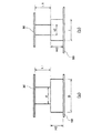
図8に示すように、高さTが120mm、幅方向寸法Dが300mm、前後方向寸法H1が80mmの合成木材であって、その上面に幅方向の全体にわたって高さt1が40mm、深さL3が40mmの凹部が形成されたものをバンパービームとして用いた。また、見掛け密度0.082g/cm3、前後方向最大寸法L1が80mm、高さ(上下方向寸法)t1が40mm、幅方向寸法(左右方向寸法)dが150mmの直方体形状のポリプロピレン系樹脂発泡粒子成形体(引張弾性率1120MPaのプロピレン−エチレンランダム共重合体)をエネルギー吸収材(合成樹脂弾性発泡体)とした。
【0055】
上記エネルギー吸収材を、上記バンパービームの凹部に、図8に示すように挿入し、図8に示すように該エネルギー吸収材の前面をバンパーの外装材として用いられるものと同質の厚み3mmの樹脂シート30にて覆い参考発明のバンパー構造を有するバンパーを作製した。次に図8に示すように樹脂シート30が上面になるようにバンパーを支持台50上に設置して落錘式動的試験機を用いて、フラットインパクター(縦40cm、横40cm、厚み3cmの鋼板の上面に高さ2cmのリブが複数形成された重量16kgもの)をバンパー最上部より103cm上の高さから水平に自由落下させフラットインパクターの平らな面が樹脂シート30へ水平に当るようにして落下衝撃試験を行った。その際の衝撃エネルギーは約162Jであった。得られた結果を、荷重−変位曲線(a)として図10に示す。尚、上記落下衝撃試験においては、図10の変位に示されるようにフラットインパクターによる衝撃エネルギーによって、エネルギー吸収材がL2に相当する40mm歪むことはなく、バンパービームとフラットインパクターは樹脂シートを介して接触することはなかった。
【0056】
参考比較例1
図9に示すように、高さTが120mm、幅方向寸法Dが300mm、前後方向寸法H2が80mmの直方体形状の合成木材をバンパービームとして用いた。また、見掛け密度0.082g/cm3、前後方向最大寸法L1が40mm、高さ(上下方向寸法)t2が80mm、幅方向寸法(左右方向寸法)dが150mmの直方体形状のポリプロピレン系樹脂発泡粒子成形体(引張弾性率1120MPaのプロピレン−エチレンランダム共重合体)をエネルギー吸収材(合成樹脂弾性発泡体)とした。
【0057】
図9に示すように、上記エネルギー吸収材を上記バンパービーム上に置き、該エネルギー吸収材をバンパーの外装材として用いられるものと同質の厚み3mmの樹脂シート30にて覆い従来のバンパー構造を有するバンパーを作成した。次に、図9に示すように樹脂シート30を上面になるようにバンパーを支持台50上に設置して参考実施例1と同様に落錘式動的試験機を用いて、落下衝撃試験を行った。得られた結果を、荷重−変位曲線(b)として図10に示す。尚、上記落下衝撃試験においては、図10の変位に示されるようにフラットインパクターによる衝撃エネルギーによって、エネルギー吸収材がL1に相当する40mm歪むことはなく、バンパービームとフラットインパクターは樹脂シートを介して接触することはなかった。
図10から、参考実施例1のバンパー構造は、参考比較例1のバンパー構造に比べ、同じ衝撃エネルギーを与えられた場合、発生荷重が小さいことが判る。
【0058】
参考実施例2
図8に示すように、高さTが120mm、幅方向寸法Dが300mm、前後方向寸法H1が80mmの合成木材であって、その上面に幅方向の全体にわたって高さt1が35mm、深さL3が50mmの凹部が形成されたものをバンパービームとして用いた。また、見掛け密度0.082g/cm3、前後方向最大寸法L1が100mm、高さ(上下方向寸法)t1が35mm、幅方向寸法(左右方向寸法)dが100mmの直方体形状のポリプロピレン系樹脂発泡粒子成形体(引張弾性率1120MPaのプロピレン−エチレンランダム共重合体)をエネルギー吸収材(合成樹脂弾性発泡体)とした。
【0059】
上記エネルギー吸収材を、上記バンパービームの凹部に、図8に示すように挿入し、図8に示すように該エネルギー吸収材の前面をバンパーの外装材として用いられるものと同質の厚み3mmの樹脂シート30にて覆い参考発明のバンパー構造を有するバンパーを作製した。この結果、エネルギー吸収材の突出部の前後方向寸法L2は50mmであり、バンパービーム凹部に挿入された部分の前後方向寸法は50mmのバンパー構造となった。
【0060】
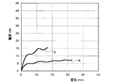
次に図8に示すように樹脂シート30を上面になるようにバンパーを支持台50上に設置して落錘式動的試験機を用いて、歩行者の脚部に相当する円柱状インパクター(外径(直径)70mm、重量21.4kgの鋼管)をバンパー最上部より715mm上の高さから、円柱状インパクターの長さ方向がエネルギー吸収材の上下方向と一致するように水平に自由落下させ落下衝撃試験を行った。その際の衝撃エネルギーは約150Jであった。また、上記落下衝撃試験においては、エネルギー吸収材がインパクターのエネルギーを変位50mm以下で完全に吸収し、インパクターが樹脂シートを介してバンパービームに衝突することはなかった。尚、脚部に加わる最大減速度を一定以下に抑えるため、発生する荷重の上限値目標を3.5kNと仮に想定した。得られた結果を、荷重−変位曲線(1)として図13に示す。
【0061】
参考比較例2
図9に示すように、高さTが120mm、幅方向寸法Dが300mm、前後方向寸法H2が80mmの直方体形状の合成木材をバンパービームとして用いた。また、見掛け密度0.082g/cm3、前後方向最大寸法L1が50mm、高さ(上下方向寸法)t2が35mm、幅方向寸法(左右方向寸法)dが100mmの直方体形状のポリプロピレン系樹脂発泡粒子成形体(引張弾性率1120MPaのプロピレン−エチレンランダム共重合体)をエネルギー吸収材(合成樹脂弾性発泡体)とした。
【0062】
図9に示すように、上記エネルギー吸収材を上記バンパービーム上に置き、該エネルギー吸収材をバンパーの外装材として用いられるものと同質の厚み3mmの樹脂シート30にて覆い従来のバンパー構造を有するバンパーを作成した。
次に、図9に示すように樹脂シート30を上面になるようにバンパーを支持台50上に設置して参考実施例2と同様に落錘式動的試験機を用いて、落下衝撃試験を行った。得られた結果を、荷重−変位曲線(2)として図13に示す。尚、上記落下衝撃試験においては、エネルギー吸収材がインパクターのエネルギーを変位50mm以下で完全に吸収し、インパクタが樹脂シートを介してバンパービームに衝突することはなかった。
【0063】
歩行者脚部の保護を目的としたバンパーでは、衝突による衝撃エネルギを吸収すると共に、発生する最大減速度を脚部に甚大な傷害が発生しない範囲に抑える必要がある。そのためには、前記の参考実施例において、図13に示した発生荷重を一定以下に制御する必要がある。よって、参考発明による参考実施例2では、底付き現象が発生せず、最大発生荷重は3.5kN以下で全エネルギーを吸収した。しかし、従来構造である参考比較例2では、変位が30mmを超えると底付き現象により発生荷重が急激に高まり、目標である3.5kNを超え、最大で5.3kNに達した。
【0064】
尚、参考実施例2、参考比較例2共に、車両の小型化、車体デザインの自由度に影響するバンパービームより前面に突出するエネルギー吸収材の車体前後方向寸法は50mmである。
このことから、従来構造である参考比較例2のバンパー構造において、発生最大荷重を一定以下(参考実施例2では3.5kN以下)に抑えるためには、バンパービームより車体前方に突出するエネルギー吸収材の前後方向寸法を更に大きくして、最大変位の割合を抑え、底付き現象を回避せねばならず、結果として車体の小型化、車体デザインの自由度に制約を与えることになる。
【0065】
また、従来のバンパー構造と比較し、参考発明又は本発明によるバンパー構造では、エネルギー吸収材の変位が進んでも、発生荷重が急激に上昇する底付き現象が発生しにくいので、発生荷重を一定以下に抑えつつ、バンパービーム前方に突出したエネルギー吸収材の寸法のほとんどを有効ストロークとして利用可能であるため、車体の小型化、車体デザインの自由度を確保することができる。
【0066】
【発明の効果】
参考発明又は本発明のバンパー構造は、バンパー芯材としての合成樹脂弾性発泡体がバンパービームの前方面に設けられた凹部内、又はバンパービームの前方面の上部及び/又は下部に設けられた段部内に位置していると共に、該発泡体の一部が該バンパービームの前方面から突出して発泡体突出部を形成し、且つ、該突出部が、前方からの衝撃エネルギー吸収時には該エネルギー量に応じて歪み、該凹部内、又は該段部が形成する空間内に収納される構造のものであるため、歩行者脚部等と衝突した場合、脚部等に甚大な傷害を与えることがなく、他車両、或いは壁面と衝突した場合であっても車体を保護することができ、該衝突後、合成樹脂弾性発泡体は大きな残留歪を生じることなく回復する。従って、相反する車体保護と歩行者脚部等保護の性能を兼備した優れたバンパー構造を実現したものである。また、更に、参考発明又は本発明のバンパー構造によってバンパーの小型化、軽量化が可能となる。
【0067】
参考発明又は本発明のバンパー構造においては、前記凹部内、又はバンパービームの前方面の上部及び/又は下部に設けられた段部内に収納されることがない膨出部又は連結部が合成樹脂弾性発泡体の前後方向の前方先端に設けられている場合、発泡体突出部が歪むことにより吸収しきれなかった衝撃エネルギーを膨出部又は連結部が吸収しバンパービームが受け止めなければならない衝撃を低減すること等が可能となり、バンパービームに対する負担を軽減することができる。
【0068】
発泡体突出部の前後方向最小寸法L2と該合成樹脂弾性発泡体の前後方向最大寸法L1との比L2/L1が、0.4〜0.9の場合、歩行者脚部等との衝突時において発泡体突出部は効果的に歩行者脚部等を保護することができる。
【0069】
前記合成樹脂弾性発泡体が特定の見掛け密度のポリプロピレン系樹脂発泡粒子成形体であることから、発泡体突出部は効果的に所期の目的を達成することができる。
【図面の簡単な説明】
【図1】参考発明のバンパー構造の一例を示す縦断面図である。
【図2】参考発明のバンパー構造の一例を示す斜視図である。
【図3】参考発明によって得られるバンパーが壁面等に衝突した場合の一例を示す縦断面図である。
【図4】参考発明の膨出部が設けられているバンパー構造の一例を示す縦断面図である。
【図5】参考発明によって得られる膨出部が設けられているバンパーが壁面等に衝突した場合の一例を示す縦断面図である。
【図6】参考発明の膨出部が設けられているバンパー構造の他の一例を示す縦断面図である。
【図7】ポリプロピレン系樹脂発泡粒子成形体の静的繰り返し圧縮と復元率との関係を示すグラフである。
【図8】(a)参考実施例の落錘式動的試験に用いるバンパー構造を説明する正面図である。
(b)参考実施例の落錘式動的試験に用いるバンパー構造を説明する側面図である。
【図9】(a)参考比較例の落錘式動的試験に用いるバンパー構造を説明する正面図である。
(b)参考比較例の落錘式動的試験に用いるバンパー構造を説明する側面図である。
【図10】フラットインパクターによる落錘式動的試験の結果を示すグラフである。
【図11】従来のバンパー構造の一例を示す縦断面図である。
【図12】参考発明のバンパー構造の他の一例を示す縦断面図である。
【図13】円柱状インパクターによる落錘式動的試験の結果を示すグラフである。
【図14】参考発明又は本発明のバンパー構造の他の一例を示す縦断面図である。
【符号の説明】
1 外装材
2 バンパービーム
3 合成樹脂弾性発泡体
4 凹部
5 発泡体突出部
6 膨出部
7 延長部
8 鍔状部
11 段部
12 連結部
13 覆い部[0001]
BACKGROUND OF THE INVENTION
The present invention relates to a bumper structure used in a vehicle such as an automobile.
[0002]
[Prior art]
The bumper of an automobile is intended to protect the vehicle body when the vehicle collides with another vehicle or a wall surface at a low speed of 10 km / hour or less. In addition, as an energy absorbing material for such a bumper, a synthetic resin foam is often used because it is lightweight and excellent in cushioning properties and has excellent resilience in repeated compression.
[0003]
However, in recent years, pedestrian protection performance that does not cause undue injury to pedestrians even in the event of a collision with pedestrians has come to be required for vehicles, and the front bumper or the energy absorbing material of the bumper includes: A new purpose is being added to protect the legs of pedestrians. In addition, in order to reduce the size and weight of the vehicle body and improve the degree of freedom of vehicle body design, there is a continuing demand for a compact bumper with higher energy absorption efficiency.
[0004]
As described above, in the conventional bumper structure for the purpose of protecting the vehicle body, the
On the other hand, in bumpers that require the ability to protect the pedestrian's legs, the legs are flexibly received in the event of a collision with the pedestrian's legs, and the maximum deceleration is set to prevent serious damage to the legs. Therefore, an energy absorbing material made of a relatively soft material is required to keep it below the allowable maximum deceleration of the part.
[0005]
For this reason, the conventional bumper for the purpose of protecting the vehicle body and the bumper for the purpose of protecting the leg part of the pedestrian require different physical properties and are difficult to achieve at the same time.
In order to solve the above-mentioned problems, the body size is reduced, the weight is reduced, and the degree of freedom in vehicle body design is impaired, but a pedestrian leg is placed on the front of a relatively hard energy absorber for vehicle protection. A bumper in which a composite energy absorbing material in which relatively soft energy absorbing materials are laminated for the purpose of protection is arranged. However, it is difficult for the bumper having such a structure to maintain the performance of a relatively soft energy absorbing material for the purpose of protecting the pedestrian leg. That is, impact energy when a vehicle with a bumper in which an energy absorbing material is used as a relatively soft material for the purpose of protecting the pedestrian's legs as described above collides with another vehicle or a wall surface. If the energy absorbing material is added to the energy absorbing material, the amount of strain exceeds the maximum strain that can maintain the resilience. Therefore, if such impact energy is repeatedly applied to the bumper, the compressive residual strain gradually accumulates. As a result, the ability to protect the pedestrian leg cannot be maintained.
[0006]
A bumper core material that satisfies all of the problems described above has not existed conventionally, and the following bumpers have only existed as conventional techniques.
[0007]
[Patent Document 1]
JP 11-208389 A [Claims]
[Patent Document 2]
JP-A-10-81182 [Claims]
[0008]
[Problems to be solved by the invention]
It is an object of the present invention to provide a bumper structure that combines the performance of protecting a vehicle body and protecting pedestrian legs and the like.
[0009]
[Means for Solving the Problems]
According to the present invention, the following bumper structure is provided.
[1] OutsideIn the bumper structure in which a synthetic resin elastic foam is placed between the equipment and the bumper beam,The foam has an apparent density of 0.11 to 0.025 g / cm. 3 A polypropylene resin foam particle molded body ofSteps are provided on the upper and / or lower part of the front surface of the bumper beam,The vertical dimension of the foam is not more than the vertical spacing of the step,The foam is located in the space formed by the step portion, and a part of the foam projects from the front surface of the bumper beam to form a foam projection, and the projection A bumper structure that is distorted according to the amount of energy when it is absorbed from the shock and is stored in a space formed by the step, [2The above-mentioned [1] is characterized in that the synthetic resin elastic foam is provided with a bulging portion at the tip of the synthetic resin elastic foam which is not accommodated in the recess when absorbing impact energy from the front.]Bumper structure, [3The ratio L2 / L1 between the minimum front-rear dimension L2 of the foam protrusion and the maximum front-rear dimension L1 of the synthetic resin elastic foam is 0.4 to 0.9. ]Or in [2]Bumper structure described.
[0010]
DETAILED DESCRIPTION OF THE INVENTION
Hereinafter, an embodiment of a bumper structure of the present invention will be described based on the drawings.
[0011]
First,The bumper structure of the present inventionA bumper structure as a reference invention will be described. The bumper structure1 and 2, a synthetic resin elastic foam 3 (hereinafter also simply referred to as foam 3) is disposed as an energy absorbing material between the
In addition, FIG.referenceFIG. 2 is a longitudinal sectional view showing an example of the bumper structure of the invention.referenceIt is a perspective view which shows an example of the bumper structure of invention.
[0012]
Reference invention Further in the present inventionAs foam 3GoodPreferably, those having a compression set measured by JIS K6767-1976 of 20% or less, more preferably 18% or less, particularly preferably 15% or less, and most preferably 10% or less are used.
[0013]
referenceIn the bumper structure of the invention, as shown in FIG. 1, a
In the present specification, the front surface of the bumper beam is a surface facing the front side of the bumper beam located on the front side of the vehicle body when the bumper having the bumper beam is attached to the vehicle body. Accordingly, the protruding
[0014]
referenceIn the invention, the
[0015]
BookinventionNo baIn the bumper structure, as shown in FIG. 14A, a
However, the
In addition, despite the provision of steps at the top and bottom of the front surface, one
[0016]
The apparent density of the
In the present specification, the front-rear direction of the foam protrusion is a direction that coincides with the front-rear direction of the vehicle body when the bumper having the structure having the foam protrusion is attached to the vehicle body. The front-rear direction, the up-down direction, and the left-right direction are respectively a direction that matches the front-rear direction of the vehicle body, a direction that matches the vertical direction of the vehicle body, and a left-right direction of the vehicle body The direction matches the direction.
[0017]
Furthermore,Reference invention orIn the bumper structure of the present invention, the
Reference invention orIn the bumper structure of the present invention, when colliding with a pedestrian leg, the
[0018]
Further, when the vehicle collides with another vehicle or a wall surface at a low speed, as shown in FIG. 3, the protruding
In addition, FIG.referenceIt is a longitudinal cross-sectional view which shows an example when the bumper obtained by invention collides with the
[0019]
Provided in the bumper beam 2StageIn the space formed by the section 11Or in the
[0020]
In addition, the shape of the
[0021]
Reference invention orAs described above, in the bumper structure of the present invention, the
[0022]
In order to make the maximum deceleration at the time of collision with the above pedestrian leg within a range not exceeding the allowable maximum deceleration necessary for protecting the leg, the vertical dimension of the
AndReference invention orIn the bumper structure of the present invention, even if the longitudinal dimension of the
[0023]
In addition, the synthetic resin constituting the
<1>In order to sufficiently absorb impact energy, the synthetic resin elastic foam must have a larger volume as the apparent density of the foam is lower, and therefore the maximum deceleration in the vertical dimension of the protrusion is reduced. Constraints and bumper beam recessesClubStepPartAs long as the vertical dimension is limited, the minimum dimension L2 in the front-rear direction of the protrusion must be increased.<2>The lower the apparent density of the synthetic resin elastic foam, the smaller the maximum deceleration in the strain range where the “bottom phenomenon” does not occur.<3>The shorter the vertical dimension of the synthetic resin elastic foam is, the smaller the contact area with the pedestrian leg is, and the maximum deceleration at the time of impact energy absorption is reduced within the range of strain that does not cause the “bottoming phenomenon”.<4>Larger impact energy can be absorbed as the longitudinal dimension of the
[0024]
Based on the above basic principle,Reference invention orThe bumper structure of the present invention can be designed as follows.
Reference invention orThe bumper beam in the bumper structure of the present invention is recessed on the front surface of the bumper beam, as shown in FIGS. 1 to 6, FIG. 12, and FIG.ClubStepPartThe overall shape, material, molding method, and the like, which are conventionally known as described in, for example, Japanese Patent Laid-Open No. 2001-322517 and Japanese Patent Laid-Open No. 11-78730, are different from those of other vehicles or wall surfaces. At the time of a collision, it has rigidity that can protect the car body by receiving impact with the bumper beam alone, together with impact energy absorption due to distortion of the energy absorbing material,Reference invention orWhen employed in the bumper structure of the present invention, the bumper beam recess with which the rear surface in the front-rear direction of the
[0025]
Therefore,Reference invention orIn designing the bumper structure of the present invention, the design of the
[0026]
MoreReference invention orAs a specific design of the bumper structure of the present invention, according to the design purpose of the
[0027]
It is more preferable to set the impact energy absorption performance higher by increasing L2 in consideration of multiple collisions. The extent to which the impact energy absorption performance is improved is determined by actually performing a collision test and checking the safety factor.
The above design procedure is an example, and other proceduresReference invention orThe bumper structure of the present invention can also be designed.
[0028]
As described above, the minimum dimension L2 in the front-rear direction of the
[0029]
The ratio L2 / L1 is also affected by the type of synthetic resin constituting the
L1 is preferably 40 to 150 mm, more preferably 50 to 130 mm, and still more preferably 60 to 120 mm. L2 is preferably 30 to 120 mm, more preferably 40 to 105 mm, and still more preferably 50 to 95 mm.
[0030]
Also recessed4 orIs step 11'sThe depth L3 is preferably 10 to 100 mm, more preferably 20 to 90 mm, and still more preferably 30 to 80 mm. Recess4 orIs step 11'sIf the depth L3 is too shallow, the same problem as when the ratio L2 / L1 is too large may occur. Also recessed4 orIs step 11'sIf the depth L3 is too deep, the same problem as when the ratio L2 / L1 is too small may occur.
[0031]
As shown in FIGS. 1, 12, and 14 (c), the
[0032]
referenceIn the bumper structure of the invention, as shown in FIG. 4, it is preferable that a bulging
[0033]
By providing the bulging portion 6referenceThe bumper structure of the invention can be a structure that positively absorbs impact energy at the time of collision with another vehicle or a wall surface. As a result, as shown in FIG. 5, for example, even when the bumper collides with the
4 is a longitudinal sectional view showing an example of the bumper structure provided with the bulging
[0034]
In the bumper structure of the present invention,
[0035]
By providing the connecting
[0036]
Above bulge6 orIs the connecting part 12Examples of the constituent material include the synthetic resin elastic foam, a synthetic resin foam other than the elastic foam, a synthetic resin non-foam, a metal honeycomb, and rubber. Among these, because the synthetic resin foam can easily change the energy absorption characteristics by adjusting the apparent density,Reference invention orAs in the present invention, the bulging portion6 orIs the connecting part 12It is suitable for the bumper structure design in a structure where the space to be provided is limited. Furthermore, the bulging part6 orIs the connecting part 12A synthetic resin elastic foam similar to the
[0037]
Also, the bulging part6 orIs the connecting
[0038]
In addition, the apparent density of the bulging
FIG. 6 is a longitudinal sectional view showing another example of the bumper structure in which the bulging
[0039]
Moreover, the
[0040]
Reference invention orIn the bumper structure of the present invention, as shown in FIGS. 14A, 14B, and 14D, the
[0041]
The structure of the material of the
As a means for attaching the
[0042]
In addition, when the
In addition, the length L2 of the
[0043]
Reference invention orIn the present invention, the front-rear direction of the cover portion is a direction that coincides with the front-rear direction of the vehicle body when the bumper having the structure having the cover portion is attached to the vehicle body.
[0044]
In this specification, the bulging part which consists of synthetic resin foams6 orIs the connecting part 12(Alternatively, the apparent density of the cover portion 13) or the protruding
[0045]
Reference invention orAs described above, the
[0046]
Reference invention orThe present inventionUsed inAs described above, the polypropylene resin expanded resin molded body has excellent rigidity and heat resistance, and can be easily molded into a desired shape. In addition, when compressed, the cross-sectional area hardly increases. So easily recessed when absorbing impact energy4 orIs the sky formed by the step 11BetweenStored.
[0047]
Examples of the polypropylene resin include propylene-butene block copolymer, propylene-butene random copolymer, ethylene-propylene block copolymer, ethylene-propylene random copolymer, ethylene-propylene-butene random terpolymer, homopolypropylene, and the like. Homopolypropylene is particularly preferred because the polypropylene expanded particle molded article is excellent in impact energy absorption efficiency.
[0048]
The PP expanded particle molded body can be produced by a conventionally known method.
[0049]
Next, the compression characteristics of the PP expanded particle molded body will be described with reference to FIG.
FIG. 7 shows the restoration rate after compression of the polypropylene resin expanded particle molded body. The compression curve shown in FIG. 7 shows an apparent density of 0.082 g / cm.3, 80 mm long, 80 mm wide, 80 mm thick cubic polypropylene resin foam molded body (test piece) is inserted between the compression plates of the compression tester, and the compression plate is lowered at a test speed of 50 mm / min. After compressing in the thickness direction to a predetermined compression rate for a thickness of 80 mm, the compression plate is immediately raised at a test speed of 50 mm / min, and the dimension in the thickness direction after 30 minutes (restoration rate% = (after 30 minutes after compression) Of the test piece in the thickness direction (mm) / 80 (mm)) × 100).
[0050]
For the second compression, the molded body, whose dimension in the thickness direction after 30 minutes in the compression test was measured, was used as a test piece and compressed to a predetermined compression ratio with respect to an initial thickness of 80 mm as in the compression test. The restoration rate after compression was determined. For the third and subsequent compressions, the restoration rate was determined in the same manner using the molded body that had been measured for the dimension in the thickness direction after 30 minutes in succession as a test piece. Curve a in FIG. 7 is a curve showing the restoration rate when the compression plate is raised after compressing the polypropylene resin expanded resin molded body to a displacement of 16 mm corresponding to 20% strain, and curve b is 50% strain. It is a curve which shows a restoration rate at the time of raising a compression board after compressing to displacement 40mm which hits. A curve c is a curve showing a restoration rate when the compression plate is raised after being compressed to a displacement of 56 mm corresponding to 70% strain. A curve d is a curve showing a restoration rate when the compression plate is raised after being compressed to a displacement of 72 mm corresponding to 90% strain.
[0051]
As shown in FIG. 7, when the PP expanded particle molded body is compressed to 70% strain, it recovers 80% or more even after four compressions. descend. That is, the PP expanded particle molded body has a compression ratio at which the recoverability is remarkably reduced. Therefore,Reference invention orIn the bumper structure of the present invention, the ratio (L2 / L1) between the minimum front-rear dimension L2 of the
[0052]
Reference invention orAs described above for the present invention, the bumper structure mainly applied to the front bumper for the purpose of combining the pedestrian leg protection performance and the vehicle body protection performance has been described.Reference invention orThe present invention is not limited to this, and based on the above technique, it is also applied to bumper structures for the purpose of protecting other parts of the human body and protecting the vehicle body, such as a bumper structure having both pedestrian waist protection performance and vehicle body protection performance. can do.
[0053]
【Example】
Next, this invention is demonstrated based on an Example.
[0054]
As shown in FIG. 8, a synthetic wood having a height T of 120 mm, a width direction dimension D of 300 mm, and a front-rear direction dimension H1 of 80 mm, the height t1 is 40 mm across the entire width direction on the upper surface, and the depth L3. Was used as a bumper beam. Apparent density 0.082 g / cm3, A polypropylene resin foam particle molded body having a rectangular parallelepiped shape having a maximum longitudinal dimension L1 of 80 mm, a height (vertical dimension) t1 of 40 mm, and a width dimension (horizontal dimension) d of 150 mm (propylene with a tensile modulus of 1120 MPa) Ethylene random copolymer) was used as an energy absorbing material (synthetic resin elastic foam).
[0055]
The energy absorbing material is inserted into the concave portion of the bumper beam as shown in FIG. 8, and the front surface of the energy absorbing material is a resin having a thickness of 3 mm which is the same as that used as a bumper exterior material as shown in FIG. Cover with sheet 30referenceA bumper having the bumper structure of the invention was produced. Next, as shown in FIG. 8, a bumper is placed on the
[0056]
referenceComparative Example 1
As shown in FIG. 9, a rectangular parallelepiped synthetic wood having a height T of 120 mm, a width direction dimension D of 300 mm, and a front-rear direction dimension H2 of 80 mm was used as a bumper beam. Apparent density 0.082 g / cm3, A polypropylene resin foam particle molded body having a rectangular parallelepiped shape having a maximum longitudinal dimension L1 of 40 mm, a height (vertical dimension) t2 of 80 mm, and a width dimension (horizontal dimension) d of 150 mm (propylene with a tensile modulus of 1120 MPa) Ethylene random copolymer) was used as an energy absorbing material (synthetic resin elastic foam).
[0057]
As shown in FIG. 9, the energy absorbing material is placed on the bumper beam, and the energy absorbing material is covered with a
From FIG.referenceThe bumper structure of Example 1 isreferenceCompared with the bumper structure of Comparative Example 1, it can be seen that the generated load is small when the same impact energy is applied.
[0058]
As shown in FIG. 8, a synthetic wood having a height T of 120 mm, a width direction dimension D of 300 mm, and a front-rear direction dimension H1 of 80 mm, the height t1 is 35 mm across the entire width direction on the upper surface, and the depth L3. Was used as a bumper beam. Apparent density 0.082 g / cm3, A rectangular solid-shaped polypropylene-based foamed resin particle molded body having a maximum longitudinal dimension L1 of 100 mm, a height (vertical dimension) t1 of 35 mm, and a width dimension (horizontal dimension) d of 100 mm (propylene having a tensile modulus of 1120 MPa) Ethylene random copolymer) was used as an energy absorbing material (synthetic resin elastic foam).
[0059]
The energy absorbing material is inserted into the concave portion of the bumper beam as shown in FIG. 8, and the front surface of the energy absorbing material is a resin having a thickness of 3 mm which is the same as that used as a bumper exterior material as shown in FIG. Cover with sheet 30referenceA bumper having the bumper structure of the invention was produced. As a result, the front-rear direction dimension L2 of the projecting portion of the energy absorbing material was 50 mm, and the front-rear direction dimension of the portion inserted into the bumper beam recess was 50 mm.
[0060]
Next, as shown in FIG. 8, a cylindrical impactor corresponding to a pedestrian's leg using a falling weight type dynamic tester with a bumper placed on the
[0061]
referenceComparative Example 2
As shown in FIG. 9, a rectangular parallelepiped synthetic wood having a height T of 120 mm, a width direction dimension D of 300 mm, and a front-rear direction dimension H2 of 80 mm was used as a bumper beam. Apparent density 0.082 g / cm3, A polypropylene resin foam particle molded body having a rectangular parallelepiped shape having a maximum longitudinal dimension L1 of 50 mm, a height (vertical dimension) t2 of 35 mm, and a width dimension (horizontal dimension) d of 100 mm (propylene having a tensile modulus of 1120 MPa) Ethylene random copolymer) was used as an energy absorbing material (synthetic resin elastic foam).
[0062]
As shown in FIG. 9, the energy absorbing material is placed on the bumper beam, and the energy absorbing material is covered with a
Next, as shown in FIG. 9, the bumper is installed on the
[0063]
In bumpers intended to protect pedestrian legs, it is necessary to absorb impact energy due to collision and limit the maximum deceleration that occurs to a range that does not cause significant injury to the legs. To that end, the abovereferenceIn the embodiment, it is necessary to control the generated load shown in FIG. Therefore,referenceAccording to inventionreferenceIn Example 2, the bottoming phenomenon did not occur, and the maximum generated load was 3.5 kN or less and all energy was absorbed. However, it has a conventional structurereferenceIn Comparative Example 2, when the displacement exceeded 30 mm, the generated load rapidly increased due to the bottoming phenomenon, exceeded the target of 3.5 kN, and reached a maximum of 5.3 kN.
[0064]
still,
From this, it is a conventional structurereferenceIn the bumper structure of Comparative Example 2, the generated maximum load is below a certain level (referenceIn order to reduce the amount of energy absorption in the second embodiment to 3.5 kN or less, it is necessary to further increase the longitudinal dimension of the energy absorber projecting forward of the vehicle body from the bumper beam to suppress the maximum displacement rate and avoid the bottoming phenomenon. As a result, the size of the vehicle body is reduced, and the degree of freedom in vehicle body design is limited.
[0065]
Compared to the conventional bumper structure,Reference invention orIn the bumper structure according to the present invention, even if the displacement of the energy absorbing material progresses, the bottoming phenomenon in which the generated load rapidly rises hardly occurs. Therefore, the energy absorbing material protruding forward of the bumper beam while keeping the generated load below a certain level. Since most of the dimensions can be used as effective strokes, it is possible to reduce the size of the vehicle body and ensure the freedom of vehicle body design.
[0066]
【The invention's effect】
Reference invention orThe bumper structure of the present invention is a recess in which a synthetic resin elastic foam as a bumper core material is provided on the front surface of a bumper beam.InsideIs the step provided on the top and / or bottom of the front surface of the bumper beamWithinAnd a part of the foam protrudes from the front surface of the bumper beam to form a foam protrusion, and the protrusion depends on the amount of energy when absorbing impact energy from the front. Distortion, the recessInsideIs the space formed by the stepWithinBecause it has a retractable structure, it does not cause serious injury to the legs when it collides with pedestrian legs, etc., and protects the vehicle even if it collides with other vehicles or walls. After the collision, the synthetic resin elastic foam recovers without causing a large residual strain. Accordingly, an excellent bumper structure that achieves both the protection of the opposite vehicle body and the protection of the pedestrian legs and the like is realized. In addition,Reference invention orThe bumper structure of the present invention makes it possible to reduce the size and weight of the bumper.
[0067]
Reference invention orIn the bumper structure of the present invention, the recessInsideIs the step provided on the top and / or bottom of the front surface of the bumper beamWithinNo bulging that can be storedClubIs consolidatedPartWhen it is provided at the front end in the front-rear direction of the synthetic resin elastic foam, the impact energy that could not be absorbed by the foam protrusion is distorted.ClubIs consolidatedPartIt is possible to reduce the impact that must be absorbed and received by the bumper beam, and the burden on the bumper beam can be reduced.
[0068]
When the ratio L2 / L1 between the minimum front-rear dimension L2 of the foam protrusion and the maximum front-rear dimension L1 of the synthetic resin elastic foam is 0.4 to 0.9, at the time of a collision with a pedestrian leg or the like The foam protrusion can effectively protect the pedestrian leg and the like.
[0069]
The synthetic resin elastic foamPolypropylene resin expanded particle molded body with specific apparent densityIsFrom the fact, Foam protrusionIs effectiveCan ultimately achieve the intended purpose..
[Brief description of the drawings]
[Figure 1]referenceIt is a longitudinal cross-sectional view which shows an example of the bumper structure of invention.
[Figure 2]referenceIt is a perspective view which shows an example of the bumper structure of invention.
[Fig. 3]referenceIt is a longitudinal cross-sectional view which shows an example when the bumper obtained by invention collides with a wall surface etc.
[Fig. 4]referenceIt is a longitudinal cross-sectional view which shows an example of the bumper structure in which the bulging part of invention is provided.
[Figure 5]referenceIt is a longitudinal cross-sectional view which shows an example when the bumper provided with the bulging part obtained by invention collides with a wall surface etc.
[Fig. 6]referenceIt is a longitudinal cross-sectional view which shows another example of the bumper structure in which the bulging part of invention is provided.
FIG. 7 is a graph showing the relationship between the static repeated compression and the restoration rate of a polypropylene resin expanded particle molded body.
FIG. 8 (a)referenceIt is a front view explaining the bumper structure used for the falling weight type dynamic test of an Example.
(B)referenceIt is a side view explaining the bumper structure used for the falling weight type dynamic test of an Example.
FIG. 9 (a)referenceIt is a front view explaining the bumper structure used for the falling weight type dynamic test of a comparative example.
(B)referenceIt is a side view explaining the bumper structure used for the falling weight type dynamic test of a comparative example.
FIG. 10 is a graph showing the results of a falling weight dynamic test using a flat impactor.
FIG. 11 is a longitudinal sectional view showing an example of a conventional bumper structure.
FIG.referenceIt is a longitudinal cross-sectional view which shows another example of the bumper structure of invention.
FIG. 13 is a graph showing the results of a falling weight dynamic test using a cylindrical impactor.
FIG. 14Reference invention orIt is a longitudinal cross-sectional view which shows another example of the bumper structure of this invention.
[Explanation of symbols]
1 Exterior material
2 Bumper beam
3 Synthetic resin elastic foam
4 recess
5 Foam protrusion
6 bulges
7 Extension
8 bowl-shaped part
11 steps
12 Connecting part
13 Cover
Claims (3)
Priority Applications (7)
| Application Number | Priority Date | Filing Date | Title |
|---|---|---|---|
| JP2003120578A JP4354209B2 (en) | 2003-03-04 | 2003-04-24 | Bumper structure |
| US10/787,140 US6983964B2 (en) | 2003-03-04 | 2004-02-27 | Vehicle bumper structure |
| DE602004006327T DE602004006327T2 (en) | 2003-03-04 | 2004-03-03 | Bumper structure for vehicle |
| EP04004912A EP1454799B1 (en) | 2003-03-04 | 2004-03-03 | Vehicle bumper structure |
| AT04004912T ATE361863T1 (en) | 2003-03-04 | 2004-03-03 | BUMPER STRUCTURE FOR VEHICLE |
| CNB2004100330559A CN100364814C (en) | 2003-03-04 | 2004-03-04 | Vehicle bumper |
| KR1020040014679A KR101051896B1 (en) | 2003-03-04 | 2004-03-04 | Vehicle bumper structure |
Applications Claiming Priority (2)
| Application Number | Priority Date | Filing Date | Title |
|---|---|---|---|
| JP2003057707 | 2003-03-04 | ||
| JP2003120578A JP4354209B2 (en) | 2003-03-04 | 2003-04-24 | Bumper structure |
Publications (2)
| Publication Number | Publication Date |
|---|---|
| JP2004322861A JP2004322861A (en) | 2004-11-18 |
| JP4354209B2 true JP4354209B2 (en) | 2009-10-28 |
Family
ID=32828977
Family Applications (1)
| Application Number | Title | Priority Date | Filing Date |
|---|---|---|---|
| JP2003120578A Expired - Fee Related JP4354209B2 (en) | 2003-03-04 | 2003-04-24 | Bumper structure |
Country Status (7)
| Country | Link |
|---|---|
| US (1) | US6983964B2 (en) |
| EP (1) | EP1454799B1 (en) |
| JP (1) | JP4354209B2 (en) |
| KR (1) | KR101051896B1 (en) |
| CN (1) | CN100364814C (en) |
| AT (1) | ATE361863T1 (en) |
| DE (1) | DE602004006327T2 (en) |
Families Citing this family (60)
| Publication number | Priority date | Publication date | Assignee | Title |
|---|---|---|---|---|
| WO2003037971A2 (en) * | 2001-11-01 | 2003-05-08 | Jsp Corporation | Process of producing expanded polypropylene resin beads |
| CN100402264C (en) | 2002-03-19 | 2008-07-16 | 株式会社Jsp | Composite foamed polypropylene resin molding and method of producing same |
| DE60325812D1 (en) * | 2002-08-28 | 2009-03-05 | Jsp Corp | Core of a bumper |
| US7226097B2 (en) * | 2002-09-30 | 2007-06-05 | Sekisui Kaseihin Kogyo Kabushiki Kaisha | Bumper absorber for pedestrain protection |
| US9105382B2 (en) | 2003-11-14 | 2015-08-11 | Tundra Composites, LLC | Magnetic composite |
| US8841358B2 (en) | 2009-04-29 | 2014-09-23 | Tundra Composites, LLC | Ceramic composite |
| JP4233042B2 (en) * | 2004-08-05 | 2009-03-04 | 本田技研工業株式会社 | Bumper structure for vehicles |
| JP4425771B2 (en) | 2004-12-16 | 2010-03-03 | 株式会社オーツカ | Impact energy absorbing material and impact energy absorbing structure |
| JP2007137114A (en) * | 2005-11-15 | 2007-06-07 | Toyota Motor Corp | Bumper structure for vehicle |
| US20070132251A1 (en) * | 2005-12-12 | 2007-06-14 | Lee Jeong H | Energy absorber applied to automobile front-bumper |
| JP4970790B2 (en) * | 2005-12-26 | 2012-07-11 | 株式会社ジェイエスピー | Bumper core material and bumper structure |
| US8141918B2 (en) * | 2006-02-24 | 2012-03-27 | Honda Motor Co., Ltd. | Pedestrian bumper system and method |
| JP5175448B2 (en) * | 2006-03-29 | 2013-04-03 | アイシン精機株式会社 | Automotive bumper equipment |
| US7484780B2 (en) * | 2006-04-12 | 2009-02-03 | Chrysler Llc | Bumper beam for automobile |
| JP4518061B2 (en) * | 2006-10-12 | 2010-08-04 | トヨタ車体株式会社 | Vehicle front shock-absorbing structure |
| US20080093867A1 (en) * | 2006-10-24 | 2008-04-24 | Shape Corporation | B-shaped beam with integrally-formed rib in face |
| DE102007006549A1 (en) * | 2007-02-09 | 2008-08-14 | Audi Ag | Bumper for motor vehicles, has bumper cross beam, where depth of retrace is matched in rest block of deformation element during predetermined loading condition |
| JP4330652B2 (en) | 2007-03-28 | 2009-09-16 | ユニプレス株式会社 | Vehicle metal absorber, vehicle bumper system, automobile bumper absorber and automobile bumper system |
| FR2914601B1 (en) * | 2007-04-06 | 2009-07-10 | Plastic Omnium Cie | ASSEMBLY OF A SHOCK BEAM AND ABSORBER |
| US7533912B2 (en) * | 2007-06-12 | 2009-05-19 | Ford Global Technologies, Llc | Hybrid energy absorber for automobile bumper |
| FR2920374A3 (en) * | 2007-08-31 | 2009-03-06 | Renault Sas | Front structure for motor vehicle, has deformable cross bar with projection part that is directed towards shield such that part deforms towards back and is housed in hollow part of rigid cross bar, in case of shock at front of vehicle |
| FR2922851B1 (en) † | 2007-10-24 | 2010-02-26 | Renault Sas | FRONT AND / OR REAR STRUCTURE FOR A MOTOR VEHICLE |
| KR100932672B1 (en) * | 2007-12-27 | 2009-12-21 | 주식회사 성우하이텍 | Bumper Beam Unit for Vehicle |
| FR2926044B1 (en) | 2008-01-09 | 2010-04-23 | Peugeot Citroen Automobiles Sa | SHOCK ABSORPTION DEVICE FOR REAR HYBRID COMPONENT OF MOTOR VEHICLE. |
| CN102898819B (en) | 2008-01-18 | 2014-10-15 | 瓦尔德瑞沃咨询集团公司 | Melt molding polymer composite and method of making and using the same |
| US7866716B2 (en) * | 2008-04-08 | 2011-01-11 | Flex-N-Gate Corporation | Energy absorber for vehicle |
| DE102008019507A1 (en) * | 2008-04-18 | 2009-10-22 | Volkswagen Ag | Bumper arrangement for motor vehicle, has bumper cross beam running through vehicle front end region in vehicle transverse direction, and deformation element overlapping cross beam elements of bumper cross beam in vehicle vertical direction |
| DE102008019510A1 (en) * | 2008-04-18 | 2009-10-22 | Volkswagen Ag | Bumper arrangement for vehicle i.e. motor vehicle, has bumper cross beam comprising energy-absorbing deformation element which covers front-sided partial area of bumper cross beam in vehicle height direction |
| DE102008019506A1 (en) * | 2008-04-18 | 2009-10-22 | Volkswagen Ag | Bumper arrangement for vehicle, particularly for motor vehicle, has bumper cross beam running in vehicle front end area in vehicle transverse direction, with energy absorbent deformation element |
| US20090315346A1 (en) * | 2008-06-20 | 2009-12-24 | David William Schelberg | Bumper reinforcement extension |
| WO2010064927A1 (en) * | 2008-12-04 | 2010-06-10 | Norsk Hydro Asa | Impact absorbing member and a method for making same |
| DE102009041769B4 (en) | 2009-09-16 | 2018-09-13 | Bayerische Motoren Werke Aktiengesellschaft | Bumper device with pedestrian protection for a motor vehicle |
| JP5821334B2 (en) * | 2011-06-30 | 2015-11-24 | いすゞ自動車株式会社 | Front underrun protector |
| DE102011051844A1 (en) * | 2011-07-14 | 2013-01-17 | Dr. Ing. H.C. F. Porsche Aktiengesellschaft | Motor vehicle, particularly passenger car, has two longitudinal carriers and transverse beam connecting longitudinal sides of longitudinal carriers, where absorber extends to side of transverse beam in vehicle transverse direction |
| KR20130064306A (en) * | 2011-12-08 | 2013-06-18 | 현대자동차주식회사 | Energy absorber for vehicle |
| US8899641B2 (en) * | 2012-10-17 | 2014-12-02 | Toyota Motor Engineering & Manufacturing North America, Inc. | Automotive bumper assembly |
| US9669787B2 (en) * | 2012-11-19 | 2017-06-06 | Toyota Shatai Kabushiki Kaisha | Shock-absorbing mechanism |
| US9016737B2 (en) * | 2013-03-14 | 2015-04-28 | Autoliv Asp, Inc. | Compressive sensor packaging techniques |
| JP6034729B2 (en) * | 2013-03-14 | 2016-11-30 | 本田技研工業株式会社 | Shock absorption mechanism for vehicles |
| DE102013007699A1 (en) * | 2013-05-04 | 2014-11-06 | GM Global Technology Operations LLC (n. d. Gesetzen des Staates Delaware) | Front end for a motor vehicle |
| GB2519810A (en) * | 2013-10-31 | 2015-05-06 | Gm Global Tech Operations Inc | Vehicle front structure |
| JP6131837B2 (en) | 2013-11-15 | 2017-05-24 | マツダ株式会社 | Vehicle front structure |
| CN105899407B (en) * | 2013-12-30 | 2018-07-06 | Tk控股公司 | Active knee protects system |
| US9248795B1 (en) | 2014-09-22 | 2016-02-02 | Toyota Motor Engineering & Manufacturing North America, Inc. | Frontal impact energy absorption members |
| DE102015111995B4 (en) * | 2015-07-23 | 2017-11-02 | Benteler Automobiltechnik Gmbh | Bumper arrangement with closing plate |
| US10065587B2 (en) | 2015-11-23 | 2018-09-04 | Flex|N|Gate Corporation | Multi-layer energy absorber |
| US9975507B2 (en) | 2016-10-06 | 2018-05-22 | Ford Global Technologies, Llc | Reinforcement block |
| WO2018169552A1 (en) * | 2017-03-17 | 2018-09-20 | Nissan North America, Inc. | Vehicle bumper assembly |
| JP6677201B2 (en) | 2017-03-23 | 2020-04-08 | トヨタ車体株式会社 | Vehicle shock absorber |
| US10532718B2 (en) * | 2017-05-18 | 2020-01-14 | Toyota Motor Engineering & Manufacturing North America, Inc. | Bumper assemblies including deformable upper energy absorbers |
| JP6798457B2 (en) * | 2017-09-15 | 2020-12-09 | トヨタ自動車株式会社 | Vampari Information |
| DE102018118622B3 (en) * | 2018-08-01 | 2020-01-09 | Dr. Ing. H.C. F. Porsche Aktiengesellschaft | Front structure of a motor vehicle |
| DE102019108742A1 (en) | 2019-04-03 | 2020-10-08 | Bayerische Motoren Werke Aktiengesellschaft | Energy absorption device |
| CN110277737A (en) * | 2019-07-24 | 2019-09-24 | 四川电器集团股份有限公司 | A kind of explosion-proof method of flame-proof switch cabinet and switchgear |
| KR102449929B1 (en) * | 2019-11-21 | 2022-09-30 | 롯데케미칼 주식회사 | Lower stiffener unit for automobile |
| KR20210062215A (en) * | 2019-11-21 | 2021-05-31 | 롯데케미칼 주식회사 | Lower stiffener unit for automobile |
| KR20210062213A (en) * | 2019-11-21 | 2021-05-31 | 롯데케미칼 주식회사 | Lower stiffener unit for automobile |
| JP7139026B2 (en) | 2020-07-28 | 2022-09-20 | 本田技研工業株式会社 | buffer structure |
| DE102020127736A1 (en) * | 2020-08-13 | 2022-02-17 | Benteler Automobiltechnik Gmbh | bumper assembly |
| DE202020107273U1 (en) | 2020-12-16 | 2022-03-18 | Rehau Automotive Se & Co. Kg | Lining part for a bumper of a motor vehicle |
Family Cites Families (32)
| Publication number | Priority date | Publication date | Assignee | Title |
|---|---|---|---|---|
| US4348042A (en) * | 1980-07-14 | 1982-09-07 | Ex-Cell-O Corporation | Vehicle bumper assembly |
| JPS5876446U (en) * | 1981-11-18 | 1983-05-24 | 住友化学工業株式会社 | Impact energy absorption bumper |
| JPS58221745A (en) * | 1982-06-19 | 1983-12-23 | Japan Styrene Paper Co Ltd | Core material of bumper of car |
| JPS60189660A (en) * | 1984-03-08 | 1985-09-27 | Japan Styrene Paper Co Ltd | Core material for automobile bumper |
| JPS61115940A (en) * | 1984-11-09 | 1986-06-03 | Mitsubishi Yuka Badische Kk | Polypropylene foam particle |
| US4756948A (en) * | 1986-07-22 | 1988-07-12 | Japan Styrene Paper Corporation | Core material for automobile bumpers |
| JPH02139155U (en) * | 1989-04-21 | 1990-11-20 | ||
| US5139297A (en) * | 1991-09-12 | 1992-08-18 | Ford Motor Company | Internal stroking bumper beam |
| US5290078A (en) * | 1992-06-01 | 1994-03-01 | General Motors Corporation | Integral fasteners for an energy absorber of a vehicular bumper assembly |
| JP3195676B2 (en) * | 1992-12-28 | 2001-08-06 | 株式会社ジエイエスピー | Method for producing expanded polyolefin resin particles |
| JPH08277340A (en) * | 1995-04-05 | 1996-10-22 | Jsp Corp | Foam grain of polypropylene homopolymer and molded product using the same |
| WO1998006777A1 (en) * | 1996-08-12 | 1998-02-19 | Jsp Corporation | Shock absorbing material |
| JP3436013B2 (en) | 1996-09-09 | 2003-08-11 | トヨタ自動車株式会社 | Bumper reinforce |
| DE69807332T2 (en) * | 1997-06-27 | 2003-04-10 | Dow Chemical Co | ENERGY ABSORBING ARTICLES MADE OF EXTRUDED THERMOPLASTIC FOAMS |
| JPH11208389A (en) | 1998-01-30 | 1999-08-03 | Nissan Motor Co Ltd | Bumper for automobile |
| DE69903593T2 (en) * | 1998-06-11 | 2003-06-18 | Jsp Corp | Molded item made of expanded and expanded propylene beads |
| US6308999B1 (en) * | 1998-07-21 | 2001-10-30 | Alcoa Inc. | Multi-material hybrid bumper |
| DE19911595A1 (en) | 1999-03-16 | 2000-09-28 | Bayerische Motoren Werke Ag | Light weight vehicle bumper comprises a light weight carrier with an elastically deformable material attached to it. |
| DE19918202A1 (en) | 1999-04-22 | 2000-10-26 | Bayer Ag | Safety bumper for automobile comprises energy absorbing elements activated by impact sensor to produce uninterrupted contour with front of main bumper structure |
| ES2189308T3 (en) | 1999-04-24 | 2003-07-01 | Ford Global Tech Inc | BUMPER FOR VEHICLES WITH OPTIMAL MECHANICAL PROPERTIES TO IMPROVE THE PROTECTION OF PEDESTRIANS. |
| US6354641B1 (en) * | 1999-08-23 | 2002-03-12 | Daimlerchrysler Corporation | Automobile bumper retention system |
| FR2805789B1 (en) | 2000-03-03 | 2002-05-24 | Renault | SHOCK ABSORBING DEVICE FOR MOTOR VEHICLE |
| SE0003418D0 (en) | 2000-09-19 | 2000-09-19 | Ssab Hardtech Ab | Bumper for vehicles |
| AU2001288078A1 (en) | 2000-09-20 | 2002-04-02 | Jsp Corporation | Expanded polypropylene resin bead |
| JP3620022B2 (en) * | 2001-02-14 | 2005-02-16 | 山久チヱイン株式会社 | Chain for 3D transfer line |
| JP4884600B2 (en) * | 2001-05-22 | 2012-02-29 | 富士重工業株式会社 | Shock absorbing bumper structure |
| ITMI20011170A1 (en) * | 2001-06-01 | 2002-12-01 | Adlev Srl | PROTECTION STRUCTURE FOR VEHICLES, SUITABLE FOR USE, IN PARTICULAR, IN THE EVENT OF IMPACTS WITH PEDESTRIANS |
| US6838488B2 (en) * | 2001-06-11 | 2005-01-04 | Jsp Corporation | Production method of foamed polypropylene resin beads |
| DE10149121B4 (en) | 2001-10-05 | 2007-02-08 | Daimlerchrysler Ag | Energy absorbing bumper |
| GB0124052D0 (en) * | 2001-10-06 | 2001-11-28 | Ford Global Tech Inc | A bumper assembly |
| WO2003037971A2 (en) | 2001-11-01 | 2003-05-08 | Jsp Corporation | Process of producing expanded polypropylene resin beads |
| CN100402264C (en) | 2002-03-19 | 2008-07-16 | 株式会社Jsp | Composite foamed polypropylene resin molding and method of producing same |
-
2003
- 2003-04-24 JP JP2003120578A patent/JP4354209B2/en not_active Expired - Fee Related
-
2004
- 2004-02-27 US US10/787,140 patent/US6983964B2/en not_active Expired - Lifetime
- 2004-03-03 AT AT04004912T patent/ATE361863T1/en not_active IP Right Cessation
- 2004-03-03 DE DE602004006327T patent/DE602004006327T2/en not_active Expired - Lifetime
- 2004-03-03 EP EP04004912A patent/EP1454799B1/en not_active Expired - Lifetime
- 2004-03-04 KR KR1020040014679A patent/KR101051896B1/en active IP Right Grant
- 2004-03-04 CN CNB2004100330559A patent/CN100364814C/en not_active Expired - Fee Related
Also Published As
| Publication number | Publication date |
|---|---|
| KR101051896B1 (en) | 2011-07-26 |
| CN100364814C (en) | 2008-01-30 |
| DE602004006327D1 (en) | 2007-06-21 |
| DE602004006327T2 (en) | 2008-01-10 |
| KR20040078599A (en) | 2004-09-10 |
| US20040174024A1 (en) | 2004-09-09 |
| JP2004322861A (en) | 2004-11-18 |
| EP1454799A1 (en) | 2004-09-08 |
| CN1533938A (en) | 2004-10-06 |
| US6983964B2 (en) | 2006-01-10 |
| ATE361863T1 (en) | 2007-06-15 |
| EP1454799B1 (en) | 2007-05-09 |
Similar Documents
| Publication | Publication Date | Title |
|---|---|---|
| JP4354209B2 (en) | Bumper structure | |
| KR101162799B1 (en) | Bumper assembly including energy absorber with vertical translation crush lobes | |
| US4072334A (en) | Energy absorbing bumper | |
| JP4163615B2 (en) | Energy absorption unit | |
| US7357444B2 (en) | Tunable geometry for energy absorbing foam to lower peak load during side impact | |
| JP4970790B2 (en) | Bumper core material and bumper structure | |
| JP2006506277A (en) | Integrated single bumper beam | |
| KR19980044132A (en) | Bumper Mounting Structure | |
| KR100986952B1 (en) | Bumper core | |
| KR20140137344A (en) | Improved energy absorbing system | |
| JP4121074B2 (en) | Front bumper core | |
| JP4723986B2 (en) | Bumper absorber | |
| JP5210117B2 (en) | Bumperin force for vehicles | |
| WO2023113011A1 (en) | Bumper absorber | |
| KR101157748B1 (en) | A bumper improved pedestrian protection functions and an automobile having thereof | |
| KR0137261Y1 (en) | Shock-absorbing bumper of the car | |
| KR200181749Y1 (en) | Impact absorbing system of bumper | |
| KR200149002Y1 (en) | Structure of bumper for an automobile | |
| JP2590434Y2 (en) | Car door structure | |
| JP2004082957A (en) | Bumper core material | |
| JP2022095377A (en) | Bumper absorber | |
| JP2005239000A (en) | Core for vehicular bumper |
Legal Events
| Date | Code | Title | Description |
|---|---|---|---|
| A621 | Written request for application examination |
Free format text: JAPANESE INTERMEDIATE CODE: A621 Effective date: 20060406 |
|
| A131 | Notification of reasons for refusal |
Free format text: JAPANESE INTERMEDIATE CODE: A131 Effective date: 20081120 |
|
| A977 | Report on retrieval |
Free format text: JAPANESE INTERMEDIATE CODE: A971007 Effective date: 20081127 |
|
| A521 | Request for written amendment filed |
Free format text: JAPANESE INTERMEDIATE CODE: A523 Effective date: 20090116 |
|
| TRDD | Decision of grant or rejection written | ||
| A01 | Written decision to grant a patent or to grant a registration (utility model) |
Free format text: JAPANESE INTERMEDIATE CODE: A01 Effective date: 20090727 |
|
| A01 | Written decision to grant a patent or to grant a registration (utility model) |
Free format text: JAPANESE INTERMEDIATE CODE: A01 |
|
| A61 | First payment of annual fees (during grant procedure) |
Free format text: JAPANESE INTERMEDIATE CODE: A61 Effective date: 20090729 |
|
| R150 | Certificate of patent or registration of utility model |
Ref document number: 4354209 Country of ref document: JP Free format text: JAPANESE INTERMEDIATE CODE: R150 Free format text: JAPANESE INTERMEDIATE CODE: R150 |
|
| FPAY | Renewal fee payment (event date is renewal date of database) |
Free format text: PAYMENT UNTIL: 20120807 Year of fee payment: 3 |
|
| FPAY | Renewal fee payment (event date is renewal date of database) |
Free format text: PAYMENT UNTIL: 20120807 Year of fee payment: 3 |
|
| FPAY | Renewal fee payment (event date is renewal date of database) |
Free format text: PAYMENT UNTIL: 20130807 Year of fee payment: 4 |
|
| R250 | Receipt of annual fees |
Free format text: JAPANESE INTERMEDIATE CODE: R250 |
|
| R250 | Receipt of annual fees |
Free format text: JAPANESE INTERMEDIATE CODE: R250 |
|
| R250 | Receipt of annual fees |
Free format text: JAPANESE INTERMEDIATE CODE: R250 |
|
| R250 | Receipt of annual fees |
Free format text: JAPANESE INTERMEDIATE CODE: R250 |
|
| R250 | Receipt of annual fees |
Free format text: JAPANESE INTERMEDIATE CODE: R250 |
|
| R250 | Receipt of annual fees |
Free format text: JAPANESE INTERMEDIATE CODE: R250 |
|
| R250 | Receipt of annual fees |
Free format text: JAPANESE INTERMEDIATE CODE: R250 |
|
| R250 | Receipt of annual fees |
Free format text: JAPANESE INTERMEDIATE CODE: R250 |
|
| R250 | Receipt of annual fees |
Free format text: JAPANESE INTERMEDIATE CODE: R250 |
|
| LAPS | Cancellation because of no payment of annual fees |