JP4353527B2 - Game machine - Google Patents

Game machine Download PDF

Info

Publication number
JP4353527B2
JP4353527B2 JP2005009236A JP2005009236A JP4353527B2 JP 4353527 B2 JP4353527 B2 JP 4353527B2 JP 2005009236 A JP2005009236 A JP 2005009236A JP 2005009236 A JP2005009236 A JP 2005009236A JP 4353527 B2 JP4353527 B2 JP 4353527B2
Authority
JP
Japan
Prior art keywords
lottery table
setting
game
external device
slot machine
Prior art date
Legal status (The legal status is an assumption and is not a legal conclusion. Google has not performed a legal analysis and makes no representation as to the accuracy of the status listed.)
Expired - Fee Related
Application number
JP2005009236A
Other languages
Japanese (ja)
Other versions
JP2006192191A (en
Inventor
友和 長村
Original Assignee
株式会社オリンピア
Priority date (The priority date is an assumption and is not a legal conclusion. Google has not performed a legal analysis and makes no representation as to the accuracy of the date listed.)
Filing date
Publication date
Application filed by 株式会社オリンピア filed Critical 株式会社オリンピア
Priority to JP2005009236A priority Critical patent/JP4353527B2/en
Publication of JP2006192191A publication Critical patent/JP2006192191A/en
Application granted granted Critical
Publication of JP4353527B2 publication Critical patent/JP4353527B2/en
Expired - Fee Related legal-status Critical Current
Anticipated expiration legal-status Critical

Links

Images

Description

本発明は、パチンコ店などの遊技場に設置して使用されるスロットマシンなどの遊技機に関するものである。   The present invention relates to a gaming machine such as a slot machine installed and used in a game hall such as a pachinko parlor.

本明細書中では遊技媒体としてメダルを用いて説明するが、遊技媒体としてはコインなど他の媒体も含む。また、「メダル(遊技媒体)投入」には、実際にメダル投入口にメダルを投入することの他に、貯留(クレジット)されたメダルをベットボタンなどによりベットすることを含む。   In this specification, description will be made using medals as game media, but the game media includes other media such as coins. “Medal (game medium) insertion” includes betting a stored (credit) medal with a bet button or the like in addition to actually inserting a medal into the medal insertion slot.

パチンコ店などの遊技場に設置して使用されるスロットマシンは、前面側が開口された箱型の収納箱と、その開口部を開閉自在に塞ぐ前面扉とからなり、収納箱の内部には、リールユニット、ホッパー装置、これらを制御する制御装置等が設置され、さらに、スロットマシンの主電源を入れ、各種制御装置に電源を供給するための電源装置が設置されている。また、この電源装置には電源供給を行う際に操作される電源供給用ボタンの他に、当たりの抽選確率が互いに異なる複数の抽選テーブルの中から1つを選択して設定する際に操作される設定変更ボタンが設けられている。   A slot machine that is installed and used in amusement halls such as pachinko parlors is composed of a box-shaped storage box whose front side is open and a front door that can be opened and closed freely. A reel unit, a hopper device, a control device for controlling them, and the like are installed, and a power supply device for turning on the main power of the slot machine and supplying power to various control devices is installed. In addition to the power supply button operated when power is supplied to the power supply device, the power supply device is operated when selecting and setting one of a plurality of lottery tables having different winning lottery probabilities. A setting change button is provided.

抽選テーブルの設定は、例えばスロットマシンの前面扉を開放し、専用の設定キーをキー穴に差し込み、設定キーをオフ位置からオン位置に回転操作した後に主電源を投入することで抽選テーブル設定モードにしてから設定変更ボタンを操作することによって行われる。そして、抽選テーブルを設定した後、設定キーをオン位置からオフ位置に回転操作すると遊技モードとなり、遊技が実行可能となる。設定変更ボタンを操作することにより遊技で用いられる抽選テーブルが設定されると、遊技の処理を行う回路基板に信号が送信されて、設定された抽選テーブルに基づいて遊技が実行される。
特開2002−224417号
The lottery table is set, for example, by opening the front door of the slot machine, inserting a dedicated setting key into the key hole, turning the setting key from the off position to the on position, and then turning on the main power. This is done by operating the setting change button. Then, after setting the lottery table, when the setting key is rotated from the on position to the off position, the game mode is set and the game can be executed. When the lottery table used in the game is set by operating the setting change button, a signal is transmitted to the circuit board for processing the game, and the game is executed based on the set lottery table.
JP 2002-224417 A

しかしながら、上述したようなスロットマシンでは、前面扉と収納箱との間に生じる隙間や、前面扉に故意に開けた穴から針金や板などの異物を収納箱の内部に侵入させ、その異物によって設定変更ボタンが操作されることにより抽選テーブルが不正に変更されてしまうという問題があった。   However, in the slot machine as described above, foreign matter such as a wire or a plate is allowed to enter the storage box through a gap formed between the front door and the storage box or a hole intentionally opened in the front door. There is a problem that the lottery table is illegally changed by operating the setting change button.

本発明は、上記課題を解決するためになされたものであり、設定変更ボタンを操作して抽選テーブルを変更する不正行為を防止することができるようにした遊技機を提供することを目的とする。   The present invention has been made to solve the above-described problems, and an object of the present invention is to provide a gaming machine capable of preventing an illegal act of changing a lottery table by operating a setting change button. .

本発明は上記目的を達成するために、当たりの抽選確率が互いに異なる複数の抽選テーブルの中から1つを選択して設定する設定手段を備え、この設定手段で設定された抽選テーブルを用いて遊技が実行される遊技機において、前記遊技機とともに用いられる外部装置が前記遊技機に接続されているか否かを電気的に識別する外部装置識別手段と、この外部装置識別手段により前記外部装置の接続が識別できないときに前記設定手段の設定操作を有効化し、外部装置の接続が識別されたときに設定手段の設定操作を無効化する設定操作制御手段とを備えたことを特徴としている。   In order to achieve the above object, the present invention includes setting means for selecting and setting one of a plurality of lottery tables having different winning lottery probabilities, and using the lottery table set by the setting means. In a gaming machine in which a game is executed, an external device identifying means for electrically identifying whether or not an external device used with the gaming machine is connected to the gaming machine, and the external device identifying means And a setting operation control unit that validates the setting operation of the setting unit when the connection cannot be identified, and invalidates the setting operation of the setting unit when the connection of the external device is identified.

また、前記外部装置識別手段により前記外部装置の接続が識別された状態でのみ遊技の実行が可能となることが好ましい。   Further, it is preferable that the game can be executed only in a state where the connection of the external device is identified by the external device identification means.

また、前記外部装置は、投入された価値媒体から読み取った価値情報を前記遊技機に入力する遊技媒体の貸し出し装置であり、前記遊技機は前記貸し出し装置から入力された前記価値情報に応じて遊技媒体を払い出す払出し装置を有することが好ましい。   The external device is a gaming medium lending device that inputs value information read from the inserted value medium to the gaming machine, and the gaming machine is configured to play games according to the value information input from the lending device. It is preferable to have a dispensing device that dispenses the medium.

また、前記外部装置は、複数台の前記遊技機との間で遊技情報の授受を行うホールコンピュータであることが好ましい。   The external device is preferably a hall computer that exchanges game information with a plurality of the gaming machines.

本発明の遊技機によれば、遊技機とともに用いられる外部装置が遊技機に接続されているか否かを外部装置識別手段が電気的に識別し、外部装置識別手段により外部装置の接続が識別できないときに設定操作制御手段が設定手段の設定操作を有効化し、外部装置の接続が識別されたときに設定操作制御手段が設定手段の設定操作を無効化するので、外部装置が遊技機に接続されているとき、すなわち遊技機及び外部装置が稼動している時間帯に設定手段の設定操作を行ったとしても当たりの抽選確率を変更することはできない。これにより設定手段による不正な設定変更を確実に防止することができる。   According to the gaming machine of the present invention, the external device identifying means electrically identifies whether or not the external device used with the gaming machine is connected to the gaming machine, and the external device identifying means cannot identify the connection of the external device. When the setting operation control means validates the setting operation of the setting means, and the setting operation control means invalidates the setting operation of the setting means when the connection of the external device is identified, the external device is connected to the gaming machine. In other words, even if the setting means is set in the time zone in which the gaming machine and the external device are operating, the winning lottery probability cannot be changed. Thereby, an unauthorized setting change by the setting means can be surely prevented.

また、外部装置識別手段により外部装置の接続が識別された状態でのみ遊技の実行が可能となるようにしたので、不正に外部装置の接続が解除され、設定手段による設定変更が行われたとしても遊技を行うことができない。   In addition, since the game can be executed only when the connection of the external device is identified by the external device identification means, it is assumed that the connection of the external device is illegally released and the setting is changed by the setting means. Can not play games.

また、外部装置は、投入された価値媒体から読み取った価値情報を遊技機に入力する遊技媒体の貸し出し装置であり、遊技機は前記貸し出し装置から入力された価値情報に応じて遊技媒体を払い出す払出し装置を有するので、価値情報を遊技機に入力することが可能な状態で貸し出し装置が遊技機に接続されているとき、すなわち遊技機及び貸し出し装置が稼動している時間帯に設定手段の設定操作を行ったとしても当たりの抽選確率を変更することはできない。これにより設定手段による不正な設定変更を確実に防止することができる。   The external device is a gaming medium lending device that inputs value information read from the input value medium to the gaming machine, and the gaming machine pays out gaming media according to the value information input from the lending device. Since the payout device is provided, the setting means is set when the lending device is connected to the gaming machine in a state where the value information can be input to the gaming machine, that is, during the time when the gaming machine and the lending device are operating. Even if an operation is performed, the winning lottery probability cannot be changed. Thereby, an unauthorized setting change by the setting means can be surely prevented.

また、外部装置は、複数台の遊技機との間で遊技情報の授受を行うホールコンピュータであるので、遊技情報の授受を行うことが可能な状態でホールコンピュータが遊技機に接続されているとき、すなわち遊技機及びホールコンピュータが稼動している時間帯に設定手段の設定操作を行ったとしても当たりの抽選確率を変更することはできない。これにより設定手段による不正な設定変更を確実に防止することができる。   In addition, since the external device is a hall computer that exchanges game information with a plurality of gaming machines, the hall computer is connected to the gaming machine in a state where gaming information can be exchanged. That is, even if the setting means is set in the time zone in which the gaming machine and the hall computer are operating, the winning lottery probability cannot be changed. Thereby, an unauthorized setting change by the setting means can be surely prevented.

本発明を適用したスロットマシン(遊技機)2について説明する前に先ずスロットマシン2で遊技を行う際に用いられるメダルの借り入れ方法について簡単に説明する。遊技者は遊技を行う前に店内に設置されているプリペイドカード券売機(不図示)でプリペイドカード53(図4参照)を購入する。そして、図1に示すように、スロットマシン2の側方に設置されているメダル貸出機(貸し出し装置)(外部装置)3にプリペイドカード53を入れることによりメダルを借り入れる。遊技者はそのメダルを用いてスロットマシン2で遊技を行うこととなる。ブリペイドカード53には磁気的方法などによって購入金額に対応した価値情報が記録されている。メダル貸出機3はスロットマシン2とともに用いられる外部装置であり、スロットマシン2とメダル貸出機3とは電気的に接続されている。プリペイドカード53に記録されている価値情報はメダル貸出機3によって読み取られ、読み取った価値情報に対応した枚数のメダルがスロットマシン2のホッパー装置30b(図2及び図3参照)によって払い出されるようになっている。   Before describing the slot machine (gaming machine) 2 to which the present invention is applied, a method for borrowing medals used when playing a game in the slot machine 2 will be briefly described. A player purchases a prepaid card 53 (see FIG. 4) with a prepaid card vending machine (not shown) installed in the store before playing the game. Then, as shown in FIG. 1, a medal is borrowed by inserting a prepaid card 53 into a medal lending machine (lending device) (external device) 3 installed on the side of the slot machine 2. The player plays a game in the slot machine 2 using the medal. The bripaid card 53 stores value information corresponding to the purchase amount by a magnetic method or the like. The medal lending machine 3 is an external device used with the slot machine 2, and the slot machine 2 and the medal lending machine 3 are electrically connected. The value information recorded on the prepaid card 53 is read by the medal lending machine 3, and the number of medals corresponding to the read value information is paid out by the hopper device 30b (see FIGS. 2 and 3) of the slot machine 2. It has become.

以下、本発明を適用したスロットマシン2の構成について図面を参照しながら説明する。スロットマシン2では、遊技モードと抽選テーブル設定モードと抽選テーブル確認モードと待機モードとが設定されている。遊技モードでは、スロットマシン2での遊技が実行可能となる。抽選テーブル設定モードでは、当たりの抽選確率が互いに異なる複数の抽選テーブルの中から1つを選択して設定することが可能となる。抽選テーブル確認モードでは、遊技で用いられるように設定されている抽選テーブルを確認することが可能となる。待機モードでは、遊技モード、抽選テーブル設定モード、抽選テーブル確認モードのいずれにも属さず、信号の入力待ちの状態となる。   The configuration of the slot machine 2 to which the present invention is applied will be described below with reference to the drawings. In the slot machine 2, a game mode, a lottery table setting mode, a lottery table confirmation mode, and a standby mode are set. In the game mode, a game in the slot machine 2 can be executed. In the lottery table setting mode, it is possible to select and set one of a plurality of lottery tables with different winning lottery probabilities. In the lottery table confirmation mode, it is possible to confirm the lottery table set to be used in the game. In the standby mode, it does not belong to any of the game mode, the lottery table setting mode, and the lottery table confirmation mode, and enters a signal input waiting state.

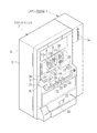
図1及び図2に示すように、スロットマシン2の筺体5は大別して、正面に開口部6aを有する収納箱6と、開口部6aを開閉自在に塞ぐ前面扉7とから構成されている。前面扉7の上部には3個の図柄表示窓8〜10が設けられ、各々の表示窓の奥に第1リール11a,第2リール11b,第3リール11cが回転自在に組み込まれている。周知のように、第1〜第3リール11a〜11cの外周には様々な図柄が一定ピッチで配列され、リールが停止した状態では対応する表示窓を通して1リール当たり3個の図柄が観察される。これにより、各リールの図柄を1個ずつ組み合わせた直線状の入賞ラインが横3本斜め2本の合計5本設定されている。   As shown in FIGS. 1 and 2, the casing 5 of the slot machine 2 is roughly divided into a storage box 6 having an opening 6a on the front surface and a front door 7 that closes the opening 6a so as to be opened and closed. Three symbol display windows 8 to 10 are provided in the upper part of the front door 7, and a first reel 11a, a second reel 11b, and a third reel 11c are rotatably incorporated in the back of each display window. As is well known, various symbols are arranged at a constant pitch on the outer periphery of the first to third reels 11a to 11c, and when the reels are stopped, three symbols are observed per reel through the corresponding display window. . As a result, a total of five straight winning lines, each of which has a combination of the symbols of each reel, are set, with three horizontal lines and two diagonal lines.

前面扉7の上部で図柄表示窓8〜10の下方にはクレジット枚数表示窓12が設けられている。クレジット枚数表示窓12の奥には、クレジット枚数表示装置13(図3参照)が設けられている。スロットマシン2では50枚を限度に適正なメダルを貯留することが可能になっており、クレジット枚数表示装置13は貯留されているメダルの枚数をクレジット枚数表示窓12を通して表示する。クレジット枚数表示窓12の側方にはエラー表示窓14が設けられている。エラー表示窓14の奥には、エラー表示窓14を通してエラーコードを表示させるエラーコード表示装置15(図3参照)が設けられている。機械動作、遊技動作に異常がある場合等には、エラー表示窓14を通して異常に応じたエラーコードが表示されるようになっている。   A credit number display window 12 is provided above the front door 7 and below the symbol display windows 8-10. Behind the credit number display window 12, a credit number display device 13 (see FIG. 3) is provided. The slot machine 2 can store appropriate medals up to 50, and the credit number display device 13 displays the number of stored medals through the credit number display window 12. An error display window 14 is provided on the side of the credit number display window 12. An error code display device 15 (see FIG. 3) for displaying an error code through the error display window 14 is provided behind the error display window 14. When there is an abnormality in the machine operation or the game operation, an error code corresponding to the abnormality is displayed through the error display window 14.

前面扉7には操作パネル16が設けられている。この操作パネル16には、1枚ベットボタン17、MAXベットボタン18、精算ボタン19、スタートレバー(設定手段)21、第1〜第3ストップボタン22〜24などの操作ボタンが設けられている。また、この操作パネル16にはメダル投入口25が設けられている。なお、これら操作ボタンやメダル投入口25の機能については周知であるため、詳細については省略する。   An operation panel 16 is provided on the front door 7. The operation panel 16 is provided with operation buttons such as a single bet button 17, a MAX bet button 18, a settlement button 19, a start lever (setting means) 21, and first to third stop buttons 22 to 24. The operation panel 16 is provided with a medal slot 25. Since the functions of these operation buttons and the medal slot 25 are well known, details are omitted.

前面扉7を開けると、収納箱6の内部には、第1〜第3リール11a〜11cの他に、ホッパーユニット30と電源装置31とが設けられている。ホッパーユニット30は、遊技の実行によりメダル投入口25から投入されたメダルを貯留するメダル貯留箱30aと、ホッパー装置(払出し装置)30bとから構成されている。ホッパー装置30bから払い出されたメダルは、メダル払い出し口32を経てメダル受け皿33に払い出される。   When the front door 7 is opened, a hopper unit 30 and a power supply device 31 are provided inside the storage box 6 in addition to the first to third reels 11a to 11c. The hopper unit 30 includes a medal storage box 30a for storing medals inserted from the medal insertion slot 25 by execution of a game, and a hopper device (payout device) 30b. The medals paid out from the hopper device 30 b are paid out to the medal tray 33 through the medal payout port 32.

電源装置31の前面側には、スロットマシン2の主電源を入れるための電源スイッチ31aと、鍵穴31bと、設定変更ボタン(設定手段)31cとが設けられている。電源スイッチ31aをオンすると主電源が投入されて各種制御装置に電源が供給される。なお、本実施形態では、スタートレバー21及び設定変更ボタン31cが、当たりの抽選確率が互いに異なる複数の抽選テーブルの中から1つを選択して設定する設定手段として機能する。   On the front side of the power supply 31, a power switch 31a for turning on the main power of the slot machine 2, a key hole 31b, and a setting change button (setting means) 31c are provided. When the power switch 31a is turned on, the main power is turned on to supply power to various control devices. In this embodiment, the start lever 21 and the setting change button 31c function as a setting unit that selects and sets one of a plurality of lottery tables having different winning lottery probabilities.

鍵穴31bは、所定の鍵(不図示)が差し込まれ、その鍵を回転操作することによりオフ位置とオン位置との間で回動するように構成されている。詳しくは後述するが、主電源が投入された状態のメダル貸出機3が通信ケーブル54(図4参照)を介してスロットマシン2に接続されていないときで、且つ電源スイッチ31aがオフのときに、鍵穴31bに所定の鍵(不図示)を差し込んで、その鍵をオフ位置からオン位置に回転操作した後、電源スイッチ31aをオンすることにより抽選テーブル設定モードになる。   The key hole 31b is configured to be rotated between an off position and an on position by inserting a predetermined key (not shown) and rotating the key. As will be described in detail later, when the medal lending machine 3 with the main power turned on is not connected to the slot machine 2 via the communication cable 54 (see FIG. 4), and when the power switch 31a is off. Then, after inserting a predetermined key (not shown) into the keyhole 31b and rotating the key from the off position to the on position, the lottery table setting mode is set by turning on the power switch 31a.

抽選テーブル設定モードでは、設定変更ボタン31cを押下操作(設定操作)することにより当選役決定部44の当選判定で用いられる当たりの抽選確率が互いに異なる複数の抽選テーブルの中から1つが選択される。抽選テーブルが選択された後、スタートレバー21を操作することにより選択された抽選テーブルが遊技で用いられるように設定される。抽選テーブルが設定された後、鍵穴31bに差し込まれている鍵をオン位置からオフ位置に回転操作すると遊技モードまたは待機モードに移行する。   In the lottery table setting mode, pressing one of the setting change buttons 31c (setting operation) selects one of a plurality of lottery tables having different winning lottery probabilities used in the winning determination of the winning combination determining unit 44. . After the lottery table is selected, the lottery table selected by operating the start lever 21 is set to be used in the game. After the lottery table is set, when the key inserted into the keyhole 31b is rotated from the on position to the off position, the game mode or standby mode is entered.

なお、主電源が投入された状態のメダル貸出機3が通信ケーブル54(図4参照)を介してスロットマシン2に接続されているときには、鍵の操作に関わらず電源スイッチ31aがオンされると遊技モードになる。また、電源スイッチ31aをオンしてスロットマシン2の主電源を投入してから鍵穴31bに所定の鍵(不図示)を差し込んでオフ位置からオン位置に回転操作することにより抽選テーブル確認モードになる。また、鍵穴31bに鍵を差し込まない状態で、あるいは鍵穴31bに差し込んだ鍵をオン位置にしない状態で、且つ、主電源が投入された状態のメダル貸出機3が通信ケーブル54(図4参照)を介してスロットマシン2に接続されていないときには、電源スイッチ31aをオンすることにより待機モードとなる。   When the medal lending machine 3 with the main power turned on is connected to the slot machine 2 via the communication cable 54 (see FIG. 4), the power switch 31a is turned on regardless of the key operation. Enter game mode. Also, after turning on the power switch 31a and turning on the main power of the slot machine 2, a predetermined key (not shown) is inserted into the keyhole 31b and rotated from the off position to the on position to enter the lottery table confirmation mode. . Further, the medal lending machine 3 in a state where the key is not inserted into the keyhole 31b or the key inserted into the keyhole 31b is not in the ON position and the main power is turned on is connected to the communication cable 54 (see FIG. 4). When not connected to the slot machine 2 via the, the power switch 31a is turned on to enter the standby mode.

前面扉7の前面には抽選テーブルコード表示窓34が設けられている。この抽選テーブルコード表示窓34の奥には、抽選テーブルコード表示窓34を通して設定変更ボタン31cを操作することにより選択された抽選テーブルの種類、スタートレバー21を操作することにより遊技で用いられるように設定された抽選テーブルの種類を表示させる抽選テーブルコード表示装置35(図3参照)が設けられている。抽選テーブル設定モード中に設定変更ボタン31cを押下操作することにより抽選テーブルが選択されると、その選択された抽選テーブルの種類を示すコードが抽選テーブルコード表示窓34を通して点滅表示され、その選択された抽選テーブルがスタートレバー21を操作することにより遊技で用いられるように設定されると、点滅表示が中止され、設定された抽選テーブルの種類を示すコードが静止表示される。抽選テーブル確認モードでは、抽選テーブルコード表示装置35により現在遊技で用いられるように設定されている抽選テーブルの種類を示すコードが抽選テーブルコード表示窓34を通して静止表示される。   A lottery table code display window 34 is provided in front of the front door 7. Behind the lottery table code display window 34, the type of the lottery table selected by operating the setting change button 31c through the lottery table code display window 34 and the game by operating the start lever 21 are used. A lottery table code display device 35 (see FIG. 3) for displaying the type of the set lottery table is provided. When a lottery table is selected by pressing the setting change button 31c during the lottery table setting mode, a code indicating the type of the selected lottery table is flashed and selected through the lottery table code display window 34. When the lottery table is set to be used in the game by operating the start lever 21, the blinking display is stopped and the code indicating the set lottery table type is statically displayed. In the lottery table confirmation mode, a code indicating the type of the lottery table that is set to be used in the current game by the lottery table code display device 35 is statically displayed through the lottery table code display window 34.

また、前面扉7の前面にはメダル貸し出し表示窓36が設けられている。このメダル貸し出し表示窓36の奥には、メダル貸出機3にプリペイドカード53を投入したことによるメダル払出し枚数の表示やメダル貸し出しの可否の表示を行うメダル貸し出し表示装置37が設けられている。   In addition, a medal rental display window 36 is provided in front of the front door 7. Behind this medal lending display window 36 is provided a medal lending display device 37 for displaying the number of medals paid out when the prepaid card 53 is inserted into the medal lending machine 3 and displaying whether or not the medal lending is possible.

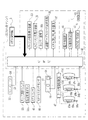
図3に示すように、スロットマシン2の作動は基本的にCPU(外部装置識別手段)(設定操作制御手段)40及びメモリ41を含む制御部42によって管制される。制御部42にはCPU40及びメモリ41の他、電子抽選部43、及び当選役決定部44が設けられている。   As shown in FIG. 3, the operation of the slot machine 2 is basically controlled by a control unit 42 including a CPU (external device identification means) (setting operation control means) 40 and a memory 41. In addition to the CPU 40 and the memory 41, the control unit 42 is provided with an electronic lottery unit 43 and a winning combination determining unit 44.

1枚ベットボタン17及びMAXベットボタン18の内部にはセンサが設けられており、それぞれのボタンが押下されたときにはCPU40に信号を入力する。CPU40は、遊技の開始に先立って投入された1〜3枚のメダルの枚数をメダルセンサ45からの検知信号か、または1枚ベットボタン17、MAXベットボタン18のいずれかからの入力信号に基づいて計数し、これにより入賞ラインの有効化本数を決定する。また、遊技を開始する際にメダル投入口25に投入されたメダルのベット枚数はCPU40に設けられたクレジットメダルカウンタ(不図示)で計数され、1枚ベットボタン17やMAXベットボタン18の操作によりメダルの投入操作が行われる毎にメダルのベット枚数はクレジット枚数から逐次に減算される。   Sensors are provided in the single bet button 17 and the MAX bet button 18, and a signal is input to the CPU 40 when each button is pressed. The CPU 40 determines the number of 1 to 3 medals inserted prior to the start of the game based on a detection signal from the medal sensor 45 or an input signal from either the 1-bet button 17 or the MAX bet button 18. And determine the number of activated winning lines. Further, the bet number of medals inserted into the medal insertion slot 25 when the game is started is counted by a credit medal counter (not shown) provided in the CPU 40, and the one bet button 17 or the MAX bet button 18 is operated. Each time a medal insertion operation is performed, the bet number of medals is successively subtracted from the credit number.

精算ボタン19の内部にはセンサが設けられており、精算ボタン19が押下操作されたときにはCPU40に信号を入力する。クレジットメダルカウンタにメダルが記憶されている状態で、精算ボタン19が押下操作されると、クレジットメダルカウンタに記憶されているメダルが全て減算され、クレジットメダルカウンタに記憶されているメダル枚数分のメダルが全てホッパー装置30bによってメダル受け皿33に払い出される。   A sensor is provided inside the settlement button 19, and a signal is input to the CPU 40 when the settlement button 19 is pressed. When the settlement button 19 is pressed while medals are stored in the credit medal counter, all the medals stored in the credit medal counter are subtracted, and medals for the number of medals stored in the credit medal counter. Are all paid out to the medal tray 33 by the hopper device 30b.

スタートスイッチセンサ46は、スタートレバー21が操作されたときにオンとなり、遊技モード中にスタートレバー21を操作すると遊技スタート信号をCPU40に入力し、抽選テーブル設定モード中にスタートレバー21を操作すると設定信号をCPU40に入力する。CPU40は、遊技スタート信号に応答して、メモリ41のROM領域に格納された遊技実行プログラムに基づいて第1〜第3リール11a〜11cを回転させるとともに遊技の処理を開始する。また、CPU40は、設定信号に応答して、設定信号に対応した設定実行信号を当選役決定部44に入力する。なお、メモリ41のRAM領域はワーキングエリアとなっており、スロットマシン2のモード設定に利用されるフラグやデータ、毎回の遊技毎に利用されるフラグやデータなどの一時的保管や書き換えなどに用いられる。   The start switch sensor 46 is turned on when the start lever 21 is operated. When the start lever 21 is operated during the game mode, a game start signal is input to the CPU 40. When the start lever 21 is operated during the lottery table setting mode, the start switch sensor 46 is set. A signal is input to the CPU 40. In response to the game start signal, the CPU 40 rotates the first to third reels 11a to 11c based on the game execution program stored in the ROM area of the memory 41 and starts the game process. Further, the CPU 40 inputs a setting execution signal corresponding to the setting signal to the winning combination determining unit 44 in response to the setting signal. The RAM area of the memory 41 is a working area, and is used for temporary storage and rewriting of flags and data used for setting the mode of the slot machine 2 and flags and data used for each game. It is done.

各リールの駆動及び停止制御は、リール駆動制御部47によって行われる。第1〜第3リール11a〜11cのそれぞれは個別のステッピングモータ48a〜48cの駆動軸に固着され、各ステッピングモータ48a〜48cの駆動を制御することにより各リールの制御が行われる。   The reel drive control unit 47 controls the drive and stop of each reel. Each of the first to third reels 11a to 11c is fixed to a drive shaft of an individual stepping motor 48a to 48c, and each reel is controlled by controlling the driving of each stepping motor 48a to 48c.

ステッピングモータ48a〜48cは供給された駆動パルスの個数に応じた回転角で回転するから、CPU40により駆動パルスの供給個数を制御することによって第1〜第3リール11a〜11cの回転角を制御することができ、また駆動パルスの供給を絶つことによりリールの停止位置を決めることができる。また、各リールには、その基準位置に反射信号部49a〜49cが一体に形成され、その一回転毎にフォトセンサ50a〜50cがそれぞれの反射信号部の通過を光電検出する。フォトセンサ50a〜50cによる検知信号は、リール毎のリセット信号としてCPU40に入力される。   Since the stepping motors 48a to 48c rotate at a rotation angle corresponding to the number of supplied drive pulses, the CPU 40 controls the rotation angle of the first to third reels 11a to 11c by controlling the number of supplied drive pulses. The stop position of the reel can be determined by stopping the supply of the drive pulse. Each reel is integrally formed with reflection signal portions 49a to 49c at its reference position, and the photosensors 50a to 50c photoelectrically detect the passage of each reflection signal portion for each rotation. Detection signals from the photosensors 50a to 50c are input to the CPU 40 as a reset signal for each reel.

CPU40にはステッピングモータ48a〜48c毎にパルスカウンタが設けられ、各々のステッピングモータ48a〜48cに供給された駆動パルスの個数を計数する。そして、フォトセンサ50a〜50cからリセット信号が入力されたときに、対応するパルスカウンタのカウント値をクリアする。したがって、それぞれのパルスカウンタには、各リールの1回転内の回転角に対応した駆動パルスの個数が逐次に更新しながら保存されることになる。   The CPU 40 is provided with a pulse counter for each of the stepping motors 48a to 48c, and counts the number of drive pulses supplied to each of the stepping motors 48a to 48c. When the reset signal is input from the photosensors 50a to 50c, the count value of the corresponding pulse counter is cleared. Therefore, the number of drive pulses corresponding to the rotation angle within one rotation of each reel is stored in each pulse counter while being sequentially updated.

メモリ41のROM領域には図柄テーブルが格納され、図柄テーブルには、各リールの基準位置からの回転角に対応した駆動パルスの個数と、リールに一定ピッチで配列されたそれぞれの図柄を表す図柄コードとが対応づけられている。したがって、リール毎にパルスカウンタのカウント値を監視することによって、例えば中央の入賞ライン上にどの図柄が移動してきているのかを識別することができ、また、さらにどの程度リールを回転させれば目的の図柄がその入賞ライン上に移動してくるのかを予測することができる。   A symbol table is stored in the ROM area of the memory 41. In the symbol table, the number of drive pulses corresponding to the rotation angle from the reference position of each reel and the symbol representing each symbol arranged on the reel at a constant pitch are stored. A code is associated. Therefore, by monitoring the count value of the pulse counter for each reel, it is possible to identify, for example, which symbol has moved on the central pay line, and to what extent the reel is further rotated. It can be predicted whether the symbol of will move on the winning line.

第1〜第3ストップボタン22〜24の内部にはセンサが設けられており、第1〜第3ストップボタン22〜24が操作されたときにCPU40にリール毎のストップ信号を入力する。スタートレバー21を操作して全リールの回転が始まり、これらの回転が定常速度に達した時点で第1〜第3ストップボタン22〜24の操作が有効化される。その後、これらを操作することによってそれぞれ対応する第1〜第3リール11a〜11cの停止制御が開始される。   Sensors are provided inside the first to third stop buttons 22 to 24, and a stop signal for each reel is input to the CPU 40 when the first to third stop buttons 22 to 24 are operated. The start lever 21 is operated to start the rotation of all reels. When these rotations reach a steady speed, the operation of the first to third stop buttons 22 to 24 is validated. Thereafter, by operating these, stop control of the corresponding first to third reels 11a to 11c is started.

CPU40は、遊技スタート信号を受けて電子抽選部43を作動させる。電子抽選部43は、乱数発生器と乱数値サンプリング回路とを含み、ゲームが開始される毎に1つの乱数値を抽選により決定する。ここで決定された乱数値は、当選役決定部44に入力される。当選役決定部44では、この入力された乱数値に応じて、現在実行されたゲームでどのような当選役を与えるかを決定する。   The CPU 40 operates the electronic lottery unit 43 in response to the game start signal. The electronic lottery unit 43 includes a random number generator and a random number sampling circuit, and determines one random value by lottery every time the game is started. The random number value determined here is input to the winning combination determination unit 44. The winning combination determining unit 44 determines what winning combination is awarded in the currently executed game according to the input random number value.

当選役決定部44には、当たりの抽選確率が互いに異なる複数(例えば6種類)の抽選テーブルが設けられている。抽選テーブルは、通常モードでのゲームでサンプリングされた乱数値が、BBモードに移行する権利を与えるBB、RBモードに移行する権利を与えるRB、所定枚数のメダルの払出しだけを行う小役当選図柄に対応する小役、メダルの投入なしに同じベット数で次回のゲームを行う権利を与えるリプレイ、一切当たりを発生させないハズレなどのいずれの図柄に属しているかの判定、すなわち当選判定に用いられる。なお、小役当選図柄は複数種類あり、それぞれに配当メダルが割り当てられている。そして、サンプリングされた乱数値がいずれの当選図柄に属した値であるかによって当選の種類と図柄が決められる。このように当選役決定部44は入力された乱数値と複数の抽選テーブルのうちのいずれか1つを用いて当たりか否かを決定する。当選役決定部44で当選判定が行われると、決定されたハズレ又は当たりの当選役の種類を示す当選役決定信号がCPU40に入力される。   The winning combination determining unit 44 is provided with a plurality of (for example, six types) lottery tables having different winning lottery probabilities. In the lottery table, the random number sampled in the game in the normal mode is BB giving the right to shift to the BB mode, the RB giving the right to shift to the RB mode, and the small role winning design that only pays out a predetermined number of medals. It is used for determining which symbol belongs to, such as a small role corresponding to, replay that gives the right to play the next game with the same number of bets without inserting medals, or a winning that does not cause any wins, that is, winning determination. There are a plurality of types of small role winning symbols, and a payout medal is assigned to each. The type and symbol of the winning are determined depending on which winning symbol the sampled random number value belongs to. In this way, the winning combination determining unit 44 determines whether or not to win using any one of the input random number value and a plurality of lottery tables. When the winning combination is determined by the winning combination determination unit 44, a winning combination determination signal indicating the type of the determined winning combination or winning combination is input to the CPU 40.

ホッパー装置30bは、当選役の種類に応じて規定枚数の配当メダルをメダル受け皿33に払い出す。なお、当選役の種類ごとに配当メダルの枚数を決めた配当テーブルはROM41に格納されており、CPU40がこれを読み取ってホッパー装置30bを駆動する。   The hopper device 30b pays out a prescribed number of payout medals to the medal tray 33 according to the type of winning combination. A payout table in which the number of payout medals is determined for each type of winning combination is stored in the ROM 41, and the CPU 40 reads this to drive the hopper device 30b.

鍵穴31bの内部にはモード選択スイッチ52が設けられている。鍵穴31bに所定の鍵が差し込まれてオフ位置からオン位置に回転操作された後に主電源が投入されると、モード選択スイッチ52がオンされ、CPU40にオン信号が入力される。その後、鍵がオン位置からオフ位置に回転操作されるとモード選択スイッチ52がオフされ、CPU40にオフ信号が入力される。なお、主電源が投入されてから鍵穴31bに所定の鍵が差し込まれてオフ位置からオン位置に回転操作されると、CPU40に抽選テーブル確認信号が入力される。その後、鍵がオン位置からオフ位置に回転操作されると、CPU40に抽選テーブル確認解除信号が入力される。   A mode selection switch 52 is provided inside the keyhole 31b. When the main power is turned on after a predetermined key is inserted into the keyhole 31 b and rotated from the off position to the on position, the mode selection switch 52 is turned on and an on signal is input to the CPU 40. Thereafter, when the key is rotated from the on position to the off position, the mode selection switch 52 is turned off, and an off signal is input to the CPU 40. When a predetermined key is inserted into the keyhole 31b after the main power is turned on and is rotated from the off position to the on position, a lottery table confirmation signal is input to the CPU 40. Thereafter, when the key is rotated from the on position to the off position, a lottery table confirmation cancellation signal is input to the CPU 40.

設定変更ボタン31cの内部にはセンサが設けられており、設定変更ボタン31cが押下操作されたことに応答してCPU40に選択信号を入力する。   A sensor is provided inside the setting change button 31c, and a selection signal is input to the CPU 40 in response to the pressing operation of the setting change button 31c.

図4に示すように、メダル貸出機3は、プリペイドカード(価値媒体)53に書き込まれている価値情報を読み取り、その読み取った価値情報をスロットマシン2に入力するためのものである。メダル貸出機3は、縦長の直方体形状に形成されており、その前面にプリペイドカード53を差し込むカード差込口3aが形成されている。背面にはメダル貸出機3の主電源を入れるための電源スイッチ(不図示)と、メダル貸出機3で得た情報をスロットマシン2に伝送するための通信ケーブル54とが設けられている。このケーブル5の先端にはプラグ54aが設けられている。   As shown in FIG. 4, the medal lending machine 3 is for reading the value information written in the prepaid card (value medium) 53 and inputting the read value information into the slot machine 2. The medal lending machine 3 is formed in a vertically long rectangular parallelepiped shape, and a card insertion slot 3a into which the prepaid card 53 is inserted is formed on the front surface thereof. On the back side, a power switch (not shown) for turning on the main power of the medal lending machine 3 and a communication cable 54 for transmitting information obtained by the medal lending machine 3 to the slot machine 2 are provided. A plug 54 a is provided at the tip of the cable 5.

図5に示すように、メダル貸出機3はCPU55aを中心にして構成され、メダル貸出機3の電気的統制を行う制御装置55と、カード差込口3aにプリペイドカード53が差し込まれた否かを識別するとともに、プリペイドカード53に書き込まれている価値情報を読み取るカード識別装置56とを備えている。   As shown in FIG. 5, the medal lending machine 3 is configured with a CPU 55a as the center, and a control device 55 that performs electrical control of the medal lending machine 3 and whether or not the prepaid card 53 is inserted into the card insertion slot 3a. And a card identification device 56 that reads the value information written on the prepaid card 53.

プラグ54aをスロットマシン2の接続コネクタ(不図示)に差し込んだ後、スロットマシン2とメダル貸出機3の主電源がオンされると、CPU55aは、スロットマシン2とメダル貸出機3とが電気的に接続されたことを示す接続完了信号を予め定められた時間間隔(例えば0.1秒間隔)で断続的にスロットマシンのCPU40に入力する。CPU40は、接続完了信号を受信すると、メダル貸出機3がスロットマシン2に接続されていると判定し、メモリ41のRAM領域にフラグαをセットする。なお、通信ケーブル54を介してスロットマシン2とメダル貸出機3とが接続されていない場合、あるいはスロットマシン2とメダル貸出機3とのうち一方の主電源がオンされ、他方の主電源がオフされている場合にはフラグαはセットされない。   When the main power of the slot machine 2 and the medal lending machine 3 is turned on after the plug 54a is inserted into the connection connector (not shown) of the slot machine 2, the CPU 55a causes the slot machine 2 and the medal lending machine 3 to be electrically connected. A connection completion signal indicating that the connection has been established is intermittently input to the CPU 40 of the slot machine at predetermined time intervals (for example, at intervals of 0.1 seconds). When receiving the connection completion signal, the CPU 40 determines that the medal lending machine 3 is connected to the slot machine 2 and sets a flag α in the RAM area of the memory 41. When the slot machine 2 and the medal lending machine 3 are not connected via the communication cable 54, or one of the slot machine 2 and the medal lending machine 3 is turned on, and the other main power is turned off. If it is set, the flag α is not set.

CPU40は、フラグαがセットされている状態でプラグ54aがスロットマシン2の接続コネクタから引き抜かれるか、あるいはフラグαがセットされている状態でメダル貸出機3の主電源がオフされることにより断続的に入力されていた接続完了信号が途絶えるとメダル貸出機3がスロットマシン2に接続されていないと判定し、メモリ41のRAM領域にセットされているフラグαを消去する。このようにCPU40は、スロットマシン2とともに用いられるメダル貸出機2がスロットマシン2に接続されているか否かを電気的に識別する外部装置識別手段として機能する。   The CPU 40 is intermittently disconnected when the plug 54a is pulled out from the connection connector of the slot machine 2 with the flag α set, or when the main power supply of the medal lending machine 3 is turned off with the flag α set. When the connection completion signal inputted in the normal state is interrupted, it is determined that the medal lending machine 3 is not connected to the slot machine 2 and the flag α set in the RAM area of the memory 41 is deleted. As described above, the CPU 40 functions as an external device identifying unit that electrically identifies whether or not the medal lending machine 2 used together with the slot machine 2 is connected to the slot machine 2.

ところで、メモリ41のRAM領域にフラグαがセットされていないときに、モード選択スイッチ52によるオン信号がCPU40に入力されると、抽選テーブル設定モードになる。抽選テーブル設定モードにおいて、CPU40は、設定変更ボタン31cからの選択信号に応答して、選択信号に対応した選択実行信号を当選役決定部44に入力する。当選役決定部44は選択実行信号に応答して複数の抽選テーブルの中から選択実行信号に対応した抽選テーブルを1つ選択する。   By the way, when the flag α is not set in the RAM area of the memory 41 and the ON signal from the mode selection switch 52 is input to the CPU 40, the lottery table setting mode is set. In the lottery table setting mode, the CPU 40 inputs a selection execution signal corresponding to the selection signal to the winning combination determining unit 44 in response to the selection signal from the setting change button 31c. The winning combination determining unit 44 selects one lottery table corresponding to the selection execution signal from the plurality of lottery tables in response to the selection execution signal.

一方、メモリ41のRAM領域にフラグαがセットされているとき、CPU40は、設定変更ボタン31cからの選択信号を無視して、選択実行信号を当選役決定部44に入力しない。これにより当選役決定部44では抽選テーブルの選択が行われない。このように、CPU40は、メダル貸出機3の接続が識別できないときに設定変更ボタン31cによる押下操作(設定操作)を有効化し、メダル貸出機3の接続が識別されたときに設定変更ボタン31cによる押下操作(設定操作)を無効化する設定操作制御手段として機能する。   On the other hand, when the flag α is set in the RAM area of the memory 41, the CPU 40 ignores the selection signal from the setting change button 31c and does not input the selection execution signal to the winning combination determination unit 44. As a result, the winning combination determination unit 44 does not select the lottery table. As described above, the CPU 40 validates the pressing operation (setting operation) by the setting change button 31c when the connection of the medal lending machine 3 cannot be identified, and by the setting change button 31c when the connection of the medal lending machine 3 is identified. It functions as a setting operation control means for invalidating the pressing operation (setting operation).

上述したように抽選テーブル設定モードにおいて抽選テーブルが選択された後、CPU40は、スタートスイッチセンサ46からの設定信号に応答して、設定信号に対応した設定実行信号を当選役決定部44に入力する。当選役決定部44は設定実行信号に応答して設定変更ボタン31cを操作することにより選択された抽選テーブルを遊技で用いるように設定する。   As described above, after the lottery table is selected in the lottery table setting mode, the CPU 40 inputs a setting execution signal corresponding to the setting signal to the winning combination determining unit 44 in response to the setting signal from the start switch sensor 46. . The winning combination determining unit 44 sets the lottery table selected by operating the setting change button 31c in response to the setting execution signal to be used in the game.

抽選テーブルが設定された後、メモリ41のRAM領域にフラグαがセットされている状態でモード選択スイッチ52によるオフ信号がCPU40に入力されると抽選テーブル設定モードから遊技モードに移行する。また、抽選テーブルが設定された後、メモリ41のRAM領域にフラグαがセットされていない状態でCPU40にオフ信号が入力されると抽選テーブル設定モードから待機モードに移行する。   After the lottery table is set, when the off signal from the mode selection switch 52 is input to the CPU 40 in a state where the flag α is set in the RAM area of the memory 41, the lottery table setting mode is shifted to the game mode. Further, after the lottery table is set, when an off signal is input to the CPU 40 in a state where the flag α is not set in the RAM area of the memory 41, the lottery table setting mode is shifted to the standby mode.

プラグ54aがスロットマシン2の接続コネクタに差し込まれていないとき、あるいはメダル貸出機3の主電源がオフのときで、且つ鍵がオン位置にない状態のときにスロットマシン2の電源スイッチ31aがオンされると待機モードになる。つまり、メモリ41のRAM領域にフラグαがセットされていない状態で、且つモード選択スイッチ52がオフのときにスロットマシン2の電源スイッチ31aがオンされると待機モードになる。   When the plug 54a is not inserted into the connection connector of the slot machine 2, or when the main power of the medal lending machine 3 is off and the key is not in the on position, the power switch 31a of the slot machine 2 is turned on. When it is done, it becomes standby mode. That is, when the flag α is not set in the RAM area of the memory 41 and when the mode selection switch 52 is off, the power switch 31a of the slot machine 2 is turned on to enter the standby mode.

待機モード中に、メダル貸出機3から接続完了信号がCPU40に入力され、メモリ41のRAM領域にフラグαがセットされると遊技モードに移行する。また、主電源が投入されていないスロットマシン2に主電源が投入された状態のメダル貸出機3が接続されている場合、スロットマシン2の電源スイッチ31aがオンされ主電源が投入されると、CPU40はメダル貸出機3からの接続完了信号に応答し、メモリ41のRAM領域にフラグαをセットする。これによりスロットマシン2は遊技モードとなる。このようにスロットマシン2は、CPU40によりメダル貸出機3の接続が識別された状態でのみ遊技の実行が可能となる。   When the connection completion signal is input from the medal lending machine 3 to the CPU 40 during the standby mode and the flag α is set in the RAM area of the memory 41, the game mode is entered. Further, when the medal lending machine 3 with the main power turned on is connected to the slot machine 2 where the main power is not turned on, when the power switch 31a of the slot machine 2 is turned on and the main power is turned on, The CPU 40 sets the flag α in the RAM area of the memory 41 in response to the connection completion signal from the medal lending machine 3. As a result, the slot machine 2 enters the game mode. As described above, the slot machine 2 can execute a game only when the CPU 40 identifies the connection of the medal lending machine 3.

なお、フラグαの有無に関わらず、鍵穴31bに鍵が差し込まれていない状態か、あるいは鍵穴31bに差し込まれた鍵がオン位置にない状態でスロットマシン2の電源スイッチ31aがオンされてから、モード選択スイッチ52がオンされると、CPU40に抽選テーブル確認信号が入力される。CPU40に抽選テーブル確認信号が入力されると抽選テーブル確認モードとなり、抽選テーブルコード表示装置35により抽選テーブルコード表示窓15を通して現在遊技で用いられるように設定されている抽選テーブルの種類を示すコードが表示される。モード選択スイッチ52がオフされると、CPU40に抽選テーブル確認解除信号が入力される。CPU40に抽選テーブル確認解除信号が入力されると抽選テーブルコード表示装置35による表示が中止され、フラグαがセットされている場合には遊技モードに移行し、フラグαがセットされていない場合には待機モードに移行する。   Regardless of the presence or absence of flag α, after the power switch 31a of the slot machine 2 is turned on with no key inserted into the keyhole 31b or with the key inserted into the keyhole 31b not in the ON position, When the mode selection switch 52 is turned on, a lottery table confirmation signal is input to the CPU 40. When a lottery table confirmation signal is input to the CPU 40, a lottery table confirmation mode is entered, and a code indicating the type of lottery table currently set to be used in the game through the lottery table code display window 15 by the lottery table code display device 35. Is displayed. When the mode selection switch 52 is turned off, a lottery table confirmation cancellation signal is input to the CPU 40. When the lottery table confirmation cancellation signal is input to the CPU 40, the display by the lottery table code display device 35 is stopped. When the flag α is set, the game mode is entered, and when the flag α is not set. Enter standby mode.

カード識別装置56には、カード差込口3aから差し込まれたプリペイドカード53をカード識別装置56の内部に引き込むカード引き込み部56aが設けられている。また、カード識別装置56には、カード引き込み部56aによって引き込まれたプリペイドカード53が予め定められた正規のプリペイドカード53であるか否かを識別する識別センサ56bが設けられている。この識別センサ56bで引き込まれたプリペイドカード53が正規のものであると識別された場合、プリペイドカード53は内部にそのまま引き込まれる。一方、引き込まれたプリペイドカード53が正規のものでないと識別された場合、カード引き込み部56aによるプリペイドカード53の引き込みを中止し、カード差込口3aへと送り出す。   The card identification device 56 is provided with a card drawing portion 56 a that draws the prepaid card 53 inserted from the card insertion slot 3 a into the card identification device 56. The card identification device 56 is provided with an identification sensor 56b for identifying whether or not the prepaid card 53 drawn by the card drawing unit 56a is a predetermined regular prepaid card 53. When the prepaid card 53 drawn by the identification sensor 56b is identified as a genuine card, the prepaid card 53 is drawn into the inside as it is. On the other hand, when it is identified that the prepaid card 53 that has been drawn is not legitimate, the drawing of the prepaid card 53 by the card drawing portion 56a is stopped and sent to the card insertion slot 3a.

カード識別装置56には、プリペイドカード53に記録されている価値情報を読み取る読み取り部56cが設けられている。CPU55aは、読み取り部56cで読み取られた価値情報に対応した価値情報信号をスロットマシン2のCPU40に入力する。   The card identification device 56 is provided with a reading unit 56 c that reads value information recorded on the prepaid card 53. The CPU 55a inputs a value information signal corresponding to the value information read by the reading unit 56c to the CPU 40 of the slot machine 2.

スロットマシン2のCPU40は、価値情報信号を受信するとホッパー装置30bを作動させ、価値情報信号に対応した枚数のメダルをホッパー装置30bに払い出させる。このように、ホッパー装置30bはメダル貸出機3から入力された価値情報に応じてメダルを払い出す払出し装置として機能する。   When receiving the value information signal, the CPU 40 of the slot machine 2 operates the hopper device 30b, and pays out the number of medals corresponding to the value information signal to the hopper device 30b. Thus, the hopper device 30b functions as a payout device that pays out medals in accordance with the value information input from the medal lending machine 3.

また、スロットマシン2のCPU40は、価値情報信号を受信するとメダル貸し出し表示装置37を作動させる。メダル貸し出し表示装置37は、価値情報信号に基づいてメダルの払出し枚数やメダル貸し出しの可否をメダル貸し出し表示窓36を通して表示する。   Further, when receiving the value information signal, the CPU 40 of the slot machine 2 operates the medal rental display device 37. The medal lending display device 37 displays the medal payout number and the medal lending availability through the medal lending display window 36 based on the value information signal.

次に、上記のように構成されたスロットマシン2の作用について図6及び図7のフローチャートを参照しながら説明する。スロットマシン2の主電源が切られている状態で鍵穴31bに所定の鍵を差し込んでその鍵をオフ位置からオン位置に回転操作した後にスロットマシン2の主電源を投入し、且つ、主電源が投入された状態のメダル貸出機3をスロットマシン2に接続した場合、フラグαがメモリ41にセットされ、遊技モードとなる。この遊技モードにおいて、CPU40は、設定変更ボタン31cの押下操作による選択信号を無視する。これにより設定変更ボタン31cの押下操作が無効化され、設定変更ボタン31cによる抽選テーブルの選択ができなくなる。   Next, the operation of the slot machine 2 configured as described above will be described with reference to the flowcharts of FIGS. With the main power of the slot machine 2 turned off, a predetermined key is inserted into the keyhole 31b, the key is rotated from the off position to the on position, and then the main power of the slot machine 2 is turned on. When the inserted medal lending machine 3 is connected to the slot machine 2, the flag α is set in the memory 41 and the game mode is set. In this game mode, the CPU 40 ignores a selection signal generated by pressing the setting change button 31c. As a result, the pressing operation of the setting change button 31c is invalidated, and the lottery table cannot be selected by the setting change button 31c.

スロットマシン2の主電源が切られている状態で鍵穴31bに所定の鍵を差し込んでその鍵をオフ位置からオン位置に回転操作した後にスロットマシン2の主電源を投入し、このとき主電源が投入された状態のメダル貸出機3がスロットマシン2に接続されていなかった場合、フラグαはメモリ41にセットされず抽選テーブル設定モードとなる。   With the main power of the slot machine 2 turned off, a predetermined key is inserted into the keyhole 31b, the key is rotated from the off position to the on position, and then the main power of the slot machine 2 is turned on. If the inserted medal lending machine 3 is not connected to the slot machine 2, the flag α is not set in the memory 41 and the lottery table setting mode is set.

抽選テーブル設定モードおいて、CPU40は、設定変更ボタン31cの押下操作による選択信号に応答して、選択実行信号を当選役決定部44に入力する。当選役決定部44は選択実行信号に応答して抽選テーブルの選択を行う。このように抽選テーブル設定モードでは設定変更ボタン31cの押下操作が有効化され、設定変更ボタン31cによる抽選テーブルの選択ができるようになる。設定変更ボタン31cにより抽選テーブルを選択した後、スタートレバー21を操作すると選択された抽選テーブルが遊技で用いられるように設定され、当選役決定部44の当選判定で用いられることとなる。   In the lottery table setting mode, the CPU 40 inputs a selection execution signal to the winning combination determination unit 44 in response to a selection signal generated by pressing the setting change button 31c. The winning combination determining unit 44 selects a lottery table in response to the selection execution signal. Thus, in the lottery table setting mode, the pressing operation of the setting change button 31c is validated, and the lottery table can be selected by the setting change button 31c. After the lottery table is selected with the setting change button 31c, when the start lever 21 is operated, the selected lottery table is set to be used in the game, and used in the winning determination of the winning combination determining unit 44.

スロットマシン2の主電源が投入された状態で鍵穴31bに所定の鍵を差し込んでその鍵をオフ位置からオン位置に回転操作すると、抽選テーブル確認モードになり、抽選モード表示装置35により抽選モード表示窓15を通して現在設定されている抽選テーブルの種類が表示される。   When a predetermined key is inserted into the keyhole 31b and the key is rotated from the off position to the on position while the main power of the slot machine 2 is turned on, the lottery table confirmation mode is entered, and the lottery mode display device 35 displays the lottery mode. The type of the lottery table currently set through the window 15 is displayed.

また、鍵穴31bに鍵を差し込まない状態で、あるいは鍵穴31bに差し込んだ鍵をオン位置にしない状態で、スロットマシン2の主電源を投入し、このときメモリ41にフラグαがセットされていなかった場合、待機モードになる。待機モード中に鍵穴31bに鍵を差し込んで鍵をオン位置にセットすると抽選テーブル確認モードになる。   Also, the main power supply of the slot machine 2 was turned on with no key inserted into the keyhole 31b or without the key inserted into the keyhole 31b being in the ON position, and the flag α was not set in the memory 41 at this time. If it is, the standby mode is set. When the key is inserted into the keyhole 31b and set to the ON position during the standby mode, the lottery table confirmation mode is set.

一方、鍵穴31bに鍵を差し込まない状態で、あるいは鍵穴31bに差し込んだ鍵をオン位置にしない状態で、スロットマシン2の主電源を投入し、このときメモリ41にフラグαがセットされていた場合、遊技モードになる。遊技モード中に鍵穴31bに鍵を差し込んで鍵をオン位置にセットすると抽選テーブル確認モードになる。抽選テーブルを変更する場合は、メダル貸出機3の主電源を投入したままの状態でメダル貸出機3をスロットマシン2に接続しておき、一旦スロットマシン2の主電源を切ってから鍵穴31bに鍵を差し込み、その鍵をオン位置にセットしてからスロットマシン2の主電源を投入すれば良い。   On the other hand, when the main power of the slot machine 2 is turned on with no key inserted into the keyhole 31b or without the key inserted into the keyhole 31b being in the ON position, and the flag α is set in the memory 41 at this time , Enter the game mode. When a key is inserted into the keyhole 31b and set to the ON position during the game mode, the lottery table confirmation mode is set. When changing the lottery table, the medal lending machine 3 is connected to the slot machine 2 with the main power of the medal lending machine 3 turned on, and once the main power of the slot machine 2 is turned off, the key hole 31b is inserted. The main power of the slot machine 2 may be turned on after inserting the key and setting the key to the ON position.

以上のように、メダル貸出機3がスロットマシン2に接続されているか否かを電気的に識別して、その接続が識別できないときに設定変更ボタン31cによる押下操作を有効化し、接続が識別されたときに設定変更ボタン31cによる押下操作を無効化するようにしたので、遊技店における営業時間帯、すわなち、スロットマシン2とメダル貸出機3とがともに稼動している時間帯に不正に設定変更ボタン31cを操作して抽選テーブルを設定するといった行為を防止することができる。   As described above, whether or not the medal lending machine 3 is connected to the slot machine 2 is electrically identified, and when the connection cannot be identified, the pressing operation by the setting change button 31c is validated, and the connection is identified. Since the pressing operation by the setting change button 31c is invalidated at the time of the game, it is illegal to operate at the amusement store business hours, that is, during the time when the slot machine 2 and the medal lending machine 3 are both operating. The act of setting the lottery table by operating the setting change button 31c can be prevented.

上記実施形態では、CPU40は、フラグαがセットされていないときに設定変更ボタン31cによる選択信号に応答し、フラグαがセットされているときに設定変更ボタン31cによる選択信号を無視するようにしたが、フラグαがセットされていないときに設定変更ボタン31cに設けられているセンサから選択信号を出力させ、フラグαがセットされているときに設定変更ボタン31cに設けられているセンサから選択信号を出力させないようにセンサを制御することにより、フラグαがセットされていないときには設定変更ボタン31cの押下操作による抽選テーブルの選択を可能にし、フラグαがセットされているときには設定変更ボタン31cの押下操作による抽選テーブルの選択を不能にするようにしても良い。また、フラグαがセットされているときに設定変更ボタン31cが押下操作できなくなるように設定変更ボタン31cをロックし、フラグαがセットされていないときにそのロックを解除するようにしても良い。また、CPU40は、フラグαがセットされていないとき、当選役決定部44の抽選テーブルを選択した後、スタートレバー21による設定信号に応答して選択した抽選テーブルを設定し、フラグαがセットされているとき、当選役決定部44の抽選テーブルを選択した後、スタートレバー21による設定信号を無視して選択した抽選テーブルの設定を行わないようにしても良く、フラグαがセットされているときに当選役決定部44の抽選テーブルが設定不能となり、フラグαがセットされていないときに当選役決定部44の抽選テーブルが設定可能となるようにCPU40によって制御されていれば良い。なお、上記実施形態における「設定」とは、広義的に、当選役決定部44の抽選テーブルを選択することの他に、選択した抽選テーブルを遊技で用いるように設定することをも含む。   In the above embodiment, the CPU 40 responds to the selection signal from the setting change button 31c when the flag α is not set, and ignores the selection signal from the setting change button 31c when the flag α is set. However, when the flag α is not set, the selection signal is output from the sensor provided in the setting change button 31c, and when the flag α is set, the selection signal is output from the sensor provided in the setting change button 31c. Is controlled so that the selection of a lottery table by pressing the setting change button 31c is enabled when the flag α is not set, and the setting change button 31c is pressed when the flag α is set. The selection of the lottery table by operation may be disabled. Alternatively, the setting change button 31c may be locked so that the setting change button 31c cannot be pressed when the flag α is set, and the lock may be released when the flag α is not set. In addition, when the flag α is not set, the CPU 40 selects the lottery table of the winning combination determining unit 44, sets the lottery table selected in response to the setting signal from the start lever 21, and the flag α is set. When the winning combination determining unit 44 selects the lottery table, the selected lottery table may not be set by ignoring the setting signal from the start lever 21, and the flag α is set. The lottery table of the winning combination determining unit 44 cannot be set, and the lottery table of the winning combination determining unit 44 may be set when the flag α is not set. The “setting” in the above embodiment broadly includes not only selecting the lottery table of the winning combination determining unit 44 but also setting the selected lottery table to be used in the game.

上記実施形態では、フラグαがセットされている場合に遊技モードとし、フラグαがセットされていない場合に待機モードとすることにより、フラグαがセットされている場合に限り遊技が実行可能となるようにしたが、フラグαがセットされていないときにはスタートスイッチセンサ46からの遊技スタート信号を無効化し、フラグαがセットされているときには遊技スタート信号を有効化するようにしても良い。また、フラグαがセットされていないときにスタートレバー21が操作できないようにスタートレバー21をロックし、フラグαがセットされたときにそのロックを解除するようにしても良く、フラグαがセットされていないときに遊技の実行を不能にし、フラグαがセットされているときに遊技の実行を可能にするようにスロットマシン2が制御されていれば良い。   In the above embodiment, the game mode can be executed only when the flag α is set by setting the game mode when the flag α is set and setting the standby mode when the flag α is not set. However, the game start signal from the start switch sensor 46 may be invalidated when the flag α is not set, and the game start signal may be validated when the flag α is set. Further, the start lever 21 may be locked so that the start lever 21 cannot be operated when the flag α is not set, and the lock may be released when the flag α is set, and the flag α is set. It is only necessary that the slot machine 2 is controlled so that the game cannot be executed when it is not, and the game can be executed when the flag α is set.

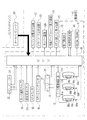
上記実施形態では、スロットマシン2とともに用いられる外部装置としてメダル貸出機3を用い、メダル貸出機3がスロットマシン2に接続されているか否かを電気的に識別し、接続が識別できないときに抽選テーブルを選択して設定する設定操作を有効化し、接続が識別されたときに設定操作を無効化するようにしたが、図8に示すようにスロットマシン2とともに用いられる外部装置として複数台のスロットマシン2との間で遊技情報の授受を行うホールコンピュータ60を用い、そのホールコンピュータ60がスロットマシン2に接続されているか否かを電気的に識別し、その識別結果に基づいて上述したような処理を実行しても良い。なお、この場合、メダル貸出機3の代わりにホールコンピュータ60を用いた他は、上記実施形態と同様の作用であるため、説明及び図示は省略する。このようにスロットマシン2に電気的に接続して使用される外部装置は適宜に変更可能である。   In the above embodiment, the medal lending machine 3 is used as an external device used together with the slot machine 2, and it is electrically identified whether or not the medal lending machine 3 is connected to the slot machine 2, and lottery is performed when the connection cannot be identified. The setting operation for selecting and setting the table is validated, and the setting operation is invalidated when a connection is identified. However, as shown in FIG. Using the hall computer 60 that exchanges game information with the machine 2, it is electrically identified whether or not the hall computer 60 is connected to the slot machine 2, and based on the identification result as described above Processing may be executed. In this case, since the operation is the same as that of the above embodiment except that the hall computer 60 is used instead of the medal lending machine 3, the description and illustration are omitted. As described above, the external device used by being electrically connected to the slot machine 2 can be appropriately changed.

上記実施形態では、断続的に入力されていた接続完了信号が途絶えるとフラグαが消去され、メモリ41にフラグαがセットされていないときに設定変更ボタン31cを押下操作することにより当選役決定部44の抽選テーブルが選択可能となるようにしたが、スロットマシン2の主電源を切らずにメダル貸出機3の主電源を切ることにより、フラグαがセットされている状態からフラグαがセットされていない状態となったことを契機に所定時間(例えば30秒)経過するまで、設定変更ボタン31cからの選択信号を無効化するようにしても良い。これにより、遊技場の営業時間帯において、スロットマシン2の主電源を切らずにメダル貸出機3の主電源を切って不正に設定変更ボタン31cの押下操作を行おうとしても直ぐには抽選テーブルの変更ができなくなるので、不正に設定変更ボタン31cを操作するといった行為が抑止される。   In the above embodiment, the flag α is deleted when the connection completion signal that is intermittently input is interrupted, and the winning combination determining unit is operated by pressing the setting change button 31c when the flag α is not set in the memory 41. 44 lottery tables can be selected, but the flag α is set from the state in which the flag α is set by turning off the main power of the medal lending machine 3 without turning off the main power of the slot machine 2. The selection signal from the setting change button 31c may be invalidated until a predetermined time (e.g., 30 seconds) elapses when the state is not changed. As a result, even if the main power of the medal lending machine 3 is turned off and the setting change button 31c is illegally pressed without turning off the main power of the slot machine 2 during the business hours of the game hall, the lottery table Since the change cannot be made, an act of illegally operating the setting change button 31c is suppressed.

上記実施形態ではスタートレバー21を操作することにより設定変更ボタン31bによって選択された抽選テーブルを遊技で用いるように設定するようにしたが、スタートレバー21以外の操作ボタン(例えば1枚ベットボタン17や精算ボタン19など)を操作することにより抽選テーブルを遊技で用いるように設定するようにしても良い。また、選択された抽選テーブルを遊技で用いるように設定する際に操作される専用の操作ボタンを設けても良い。   In the above embodiment, the lottery table selected by the setting change button 31b is set to be used in the game by operating the start lever 21, but operation buttons other than the start lever 21 (for example, the single bet button 17 or the The lottery table may be set to be used in the game by operating the checkout button 19 or the like. Further, a dedicated operation button that is operated when setting the selected lottery table to be used in the game may be provided.

上記実施形態ではスロットマシン2を例に挙げて説明したが、パチンコ機などの各種遊技機についても本発明は適用できる。   In the above embodiment, the slot machine 2 has been described as an example, but the present invention can also be applied to various gaming machines such as a pachinko machine.

スロットマシンとメダル貸出機の外観を示す斜視図である。It is a perspective view which shows the external appearance of a slot machine and a medal lending machine. 前面扉を取り外した状態のスロットマシンであり、スロットマシンの内部の構成を示す斜視図である。It is a slot machine of the state where the front door was removed, and is a perspective view showing an internal configuration of the slot machine. スロットマシンの電気的構成を示す機能ブロック図である。It is a functional block diagram showing an electrical configuration of the slot machine. メダル貸出機の外観を示す斜視図である。It is a perspective view which shows the external appearance of a medal lending machine. メダル貸出機の電気的構成を示す機能ブロック図である。It is a functional block diagram which shows the electric constitution of a medal lending machine. 本発明のスロットマシンにおける処理の流れを示すフローチャートである。4 is a flowchart showing a flow of processing in the slot machine of the present invention. 本発明のスロットマシンにおける処理の流れを示すフローチャートである。4 is a flowchart showing a flow of processing in the slot machine of the present invention. ホールコンピュータが接続されたスロットマシンの電気的構成を示す機能ブロック図である。It is a functional block diagram showing an electrical configuration of the slot machine to which the hall computer is connected.

符号の説明Explanation of symbols

2 スロットマシン(遊技機)
3 メダル貸出機(貸し出し装置)(外部装置)
21 スタートレバー(設定手段)
30b ホッパー装置(払出し装置)
31c 設定変更ボタン(設定手段)
40 CPU(設定操作制御手段)(外部装置識別手段)
60 ホールコンピュータ(外部装置)
2 Slot machines (game machines)
3 Medal lending machine (lending device) (external device)
21 Start lever (setting means)
30b Hopper device (dispensing device)
31c Setting change button (setting means)
40 CPU (setting operation control means) (external device identification means)
60 hall computer (external device)

Claims (4)

当たりの抽選確率が互いに異なる複数の抽選テーブルの中から1つを選択して設定する設定手段を備え、この設定手段で設定された抽選テーブルを用いて遊技が実行される遊技機において、
前記遊技機とともに用いられる外部装置が前記遊技機に接続されているか否かを電気的に識別する外部装置識別手段と、
この外部装置識別手段により前記外部装置の接続が識別できないときに前記設定手段の設定操作を有効化し、外部装置の接続が識別されたときに設定手段の設定操作を無効化する設定操作制御手段とを備えたことを特徴とする遊技機。
In a gaming machine that includes a setting unit that selects and sets one of a plurality of lottery tables having different winning lottery probabilities, and a game is executed using the lottery table set by the setting unit.
An external device identifying means for electrically identifying whether or not an external device used with the gaming machine is connected to the gaming machine;
A setting operation control unit that validates the setting operation of the setting unit when the connection of the external device cannot be identified by the external device identification unit, and invalidates the setting operation of the setting unit when the connection of the external device is identified; A gaming machine characterized by comprising:
前記外部装置識別手段により前記外部装置の接続が識別された状態でのみ遊技の実行が可能となることを特徴とする請求項1記載の遊技機。   2. The gaming machine according to claim 1, wherein the game can be executed only when the connection of the external device is identified by the external device identification means. 前記外部装置は、投入された価値媒体から読み取った価値情報を前記遊技機に入力する遊技媒体の貸し出し装置であり、前記遊技機は前記貸し出し装置から入力された前記価値情報に応じて遊技媒体を払い出す払出し装置を有することを特徴とする請求項1または2記載の遊技機。   The external device is a gaming medium lending device that inputs value information read from the inserted value medium to the gaming machine, and the gaming machine stores gaming media according to the value information input from the lending device. 3. The gaming machine according to claim 1, further comprising a payout device for paying out. 前記外部装置は、複数台の前記遊技機との間で遊技情報の授受を行うホールコンピュータであることを特徴とする請求項1または2記載の遊技機。
The gaming machine according to claim 1 or 2, wherein the external device is a hall computer that exchanges gaming information with a plurality of the gaming machines.
JP2005009236A 2005-01-17 2005-01-17 Game machine Expired - Fee Related JP4353527B2 (en)

Priority Applications (1)

Application Number Priority Date Filing Date Title
JP2005009236A JP4353527B2 (en) 2005-01-17 2005-01-17 Game machine

Applications Claiming Priority (1)

Application Number Priority Date Filing Date Title
JP2005009236A JP4353527B2 (en) 2005-01-17 2005-01-17 Game machine

Publications (2)

Publication Number Publication Date
JP2006192191A JP2006192191A (en) 2006-07-27
JP4353527B2 true JP4353527B2 (en) 2009-10-28

Family

ID=36798705

Family Applications (1)

Application Number Title Priority Date Filing Date
JP2005009236A Expired - Fee Related JP4353527B2 (en) 2005-01-17 2005-01-17 Game machine

Country Status (1)

Country Link
JP (1) JP4353527B2 (en)

Families Citing this family (1)

* Cited by examiner, † Cited by third party
Publication number Priority date Publication date Assignee Title
JP4768694B2 (en) * 2007-09-27 2011-09-07 株式会社ジェッター Game media rental machine

Also Published As

Publication number Publication date
JP2006192191A (en) 2006-07-27

Similar Documents

Publication Publication Date Title
JP4644004B2 (en) Game machine
JP2006014773A (en) Game machine
JP2012205953A (en) Game machine
JP4401312B2 (en) Game machine
JP2006230475A (en) Game machine
JP2006175268A (en) Game machine
JP2007202696A (en) Game machine
JP4125624B2 (en) Game machine
JP4353527B2 (en) Game machine
JP4979913B2 (en) Game machine
JP2005342046A (en) Game machine
JP2006263035A (en) Game machine and control method of game machine
JP4157457B2 (en) Game machine
JP2002346054A (en) Game machine, program and recording medium
JP4334002B2 (en) Game machine
JP4520239B2 (en) Game machine
JP2007105510A (en) Game machine
JP2005131378A (en) Game machine
JP2007136218A (en) Game machine
JP2006198316A (en) Game machine
JP2006198164A (en) Game machine
JP4425658B2 (en) Game machine
JP2004358077A (en) Game machine
JP2006239190A (en) Game machine
JP2023086392A (en) game device

Legal Events

Date Code Title Description
A131 Notification of reasons for refusal

Free format text: JAPANESE INTERMEDIATE CODE: A131

Effective date: 20090212

TRDD Decision of grant or rejection written
A01 Written decision to grant a patent or to grant a registration (utility model)

Free format text: JAPANESE INTERMEDIATE CODE: A01

Effective date: 20090722

A01 Written decision to grant a patent or to grant a registration (utility model)

Free format text: JAPANESE INTERMEDIATE CODE: A01

A61 First payment of annual fees (during grant procedure)

Free format text: JAPANESE INTERMEDIATE CODE: A61

Effective date: 20090727

R150 Certificate of patent or registration of utility model

Free format text: JAPANESE INTERMEDIATE CODE: R150

FPAY Renewal fee payment (event date is renewal date of database)

Free format text: PAYMENT UNTIL: 20120807

Year of fee payment: 3

FPAY Renewal fee payment (event date is renewal date of database)

Free format text: PAYMENT UNTIL: 20120807

Year of fee payment: 3

FPAY Renewal fee payment (event date is renewal date of database)

Free format text: PAYMENT UNTIL: 20130807

Year of fee payment: 4

R250 Receipt of annual fees

Free format text: JAPANESE INTERMEDIATE CODE: R250

S531 Written request for registration of change of domicile

Free format text: JAPANESE INTERMEDIATE CODE: R313531

R350 Written notification of registration of transfer

Free format text: JAPANESE INTERMEDIATE CODE: R350

R250 Receipt of annual fees

Free format text: JAPANESE INTERMEDIATE CODE: R250

R250 Receipt of annual fees

Free format text: JAPANESE INTERMEDIATE CODE: R250

R250 Receipt of annual fees

Free format text: JAPANESE INTERMEDIATE CODE: R250

LAPS Cancellation because of no payment of annual fees