JP4352629B2 - Damper for automobile seat and automobile seat equipped with this damper - Google Patents
Damper for automobile seat and automobile seat equipped with this damper Download PDFInfo
- Publication number
- JP4352629B2 JP4352629B2 JP2001130296A JP2001130296A JP4352629B2 JP 4352629 B2 JP4352629 B2 JP 4352629B2 JP 2001130296 A JP2001130296 A JP 2001130296A JP 2001130296 A JP2001130296 A JP 2001130296A JP 4352629 B2 JP4352629 B2 JP 4352629B2
- Authority
- JP
- Japan
- Prior art keywords
- housing
- gap
- forming member
- seat
- damper
- Prior art date
- Legal status (The legal status is an assumption and is not a legal conclusion. Google has not performed a legal analysis and makes no representation as to the accuracy of the status listed.)
- Expired - Fee Related
Links
Images


Classifications
-
- B—PERFORMING OPERATIONS; TRANSPORTING
- B60—VEHICLES IN GENERAL
- B60N—SEATS SPECIALLY ADAPTED FOR VEHICLES; VEHICLE PASSENGER ACCOMMODATION NOT OTHERWISE PROVIDED FOR
- B60N2/00—Seats specially adapted for vehicles; Arrangement or mounting of seats in vehicles
- B60N2/24—Seats specially adapted for vehicles; Arrangement or mounting of seats in vehicles for particular purposes or particular vehicles
- B60N2/30—Non-dismountable or dismountable seats storable in a non-use position, e.g. foldable spare seats
- B60N2/3038—Cushion movements
- B60N2/304—Cushion movements by rotation only
- B60N2/3045—Cushion movements by rotation only about transversal axis
- B60N2/305—Cushion movements by rotation only about transversal axis the cushion being hinged on the vehicle frame
-
- B—PERFORMING OPERATIONS; TRANSPORTING
- B60—VEHICLES IN GENERAL
- B60N—SEATS SPECIALLY ADAPTED FOR VEHICLES; VEHICLE PASSENGER ACCOMMODATION NOT OTHERWISE PROVIDED FOR
- B60N2/00—Seats specially adapted for vehicles; Arrangement or mounting of seats in vehicles
- B60N2/24—Seats specially adapted for vehicles; Arrangement or mounting of seats in vehicles for particular purposes or particular vehicles
- B60N2/30—Non-dismountable or dismountable seats storable in a non-use position, e.g. foldable spare seats
- B60N2/3002—Non-dismountable or dismountable seats storable in a non-use position, e.g. foldable spare seats back-rest movements
- B60N2/3004—Non-dismountable or dismountable seats storable in a non-use position, e.g. foldable spare seats back-rest movements by rotation only
- B60N2/3009—Non-dismountable or dismountable seats storable in a non-use position, e.g. foldable spare seats back-rest movements by rotation only about transversal axis
- B60N2/3011—Non-dismountable or dismountable seats storable in a non-use position, e.g. foldable spare seats back-rest movements by rotation only about transversal axis the back-rest being hinged on the cushion, e.g. "portefeuille movement"
Description
【0001】
【発明の属する技術分野】
本発明は、自動車の例えば回動自在(跳ね上げ自在)にされたリヤシートの回動エネルギを吸収して、リヤシートの跳ね上げ時又はその戻し時の衝撃、リヤシートのアンロック時の急制動による急激な跳ね上げ及び跳ね上げられたリヤシートの急加速による急激な戻り等をなくし得る自動車シート用のダンパ及びこのダンパを具備した自動車シートに関する。
【0002】
【発明が解決しようとする課題】
自動車シートの背もたれ用のダンパとしては、流体を利用したものが知られているが、斯かる流体を利用したダンパでは、大きな減衰力を得るには大型にならざるを得ない上に、流体の漏出を阻止するための大掛かりなシールを必要とする。特に、大きな車内居住空間を確保するために、背もたれを折り畳み、その後、シートを跳ね上げるようにした自動車シートのダンパでは、背もたれ及びシートの合計荷重に基づく大きな回動エネルギを減衰する必要があるために、単に流体を利用した小型のダンパでは、目的の大きな減衰を得ることが困難である。
【0003】
本発明は、前記諸点に鑑みてなされたものであって、その目的とするところは、大きな減衰力を得ることができる上に小型にでき、特に背もたれを折り畳み、その後、シートを跳ね上げるようにした自動車シートに好適なダンパ及びこのダンパを具備した自動車シートを提供することにある。
【0004】
【課題を解決するための手段】
本発明の第一の態様の自動車シート用のダンパは、アーム部及びハウジング本体を一体的に有したハウジングと、ハウジング本体内に回転自在に収容されていると共にハウジング本体の内面と協働して隙間を形成する隙間形成部材と、隙間に配されたシリコン系未加硫ゴムとを具備しており、ここで、ハウジングには、アーム部を介して自動車のシートの回動が伝達されるようになっており、隙間形成部材は、自動車のシートが回動自在に設置されるシャーシに対して固定されるようになっている。
【0005】
本発明の第二の態様の自動車シート用のダンパは、アーム部及びハウジング本体を一体的に有したハウジングと、ハウジング本体内に回転自在に収容されていると共にハウジング本体の内面と協働して隙間を形成する隙間形成部材と、隙間に配されたシリコン系未加硫ゴムとを具備しており、ここで、ハウジングは、自動車のシートが回動自在に設置されるシャーシに対してアーム部を介して固定されるようになっており、隙間形成部材には、自動車のシートの回動が伝達されるようになっている。
【0006】
本発明の第三の態様の自動車シート用のダンパは、鍔部及びハウジング本体を一体的に有したハウジングと、ハウジング本体内に回転自在に収容されていると共にハウジング本体の内面と協働して隙間を形成する隙間形成部材と、隙間に配されたシリコン系未加硫ゴムとを具備しており、ここで、ハウジングには、鍔部を介して自動車のシートの回動が伝達されるようになっており、隙間形成部材は、自動車のシートが回動自在に設置されるシャーシに対して固定されるようになっている。
【0007】
本発明の第四の態様の自動車シート用のダンパは、鍔部及びハウジング本体を一体的に有したハウジングと、ハウジング本体内に回転自在に収容されていると共にハウジング本体の内面と協働して隙間を形成する隙間形成部材と、隙間に配されたシリコン系未加硫ゴムとを具備しており、ハウジングは、自動車のシートが回動自在に設置されるシャーシに対して鍔部を介して固定されるようになっており、隙間形成部材には、自動車のシートの回動が伝達されるようになっている。
【0008】
第一から第四の態様の自動車シート用のダンパによれば、シリコン系未加硫ゴムでもって減衰機能を得るようにしているために、摩耗の虞もない上に、漏出防止のためのシールを省き得て、しかも、軽量且つ小型でも大きな減衰力を容易に得ることができる。
【0009】
シリコン系未加硫ゴムは、本発明の第五の態様の自動車シート用のダンパのように、30以上から420以下の可塑度を有していればよいが、好ましくは、本発明の第六の態様の自動車シート用のダンパのように、60以上から320以下の可塑度を有しており、より好ましくは、本発明の第七の態様の自動車シート用のダンパのように、160以上から320以下の可塑度を有している。
【0010】
本発明における可塑度は、ASTM等により規格化されたウィリアム可塑度計で測定した値であって、具体的には、上下2枚の平行板に直径約1.43cm、高さ1.27cmの円柱形で容積2ccのシリコン系未加硫ゴムをはさみ、70℃〜100℃で5kgの荷重により圧縮し、3分間加圧後のシリコン系未加硫ゴムの高さ(mm/100)により表したものである。
【0011】
本発明においては、シリコン系未加硫ゴムは、上述のように、30以上から420以下の可塑度を有していればよいが、30より小さい可塑度であると、流動し易くなってハウジング本体と隙間形成部材との間の隙間に配されたシリコン系未加硫ゴムに対して漏出を防止するための十分なシールを必要とする上に、大きな減衰力を期待できなくなり、420より大きい可塑度であると、ハウジング本体及び隙間形成部材の接触面とのなじみが殆どなくなり、ハウジング本体及び隙間形成部材の互いの相対的な回転においてシリコン系未加硫ゴムに対してハウジング本体及び隙間形成部材が滑ってシリコン系未加硫ゴムの変形による実質的な減衰力を得られ難くなり、また、滑りを防止するために斯かるシリコン系未加硫ゴムに接するハウジング本体及び隙間形成部材の面を凹凸面としてシリコン系未加硫ゴムを掴むようにしても、420より大きい可塑度のシリコン系未加硫ゴムは極めて脆いために、ハウジング本体及び隙間形成部材の互いの相対的な回転においてシリコン系未加硫ゴムがたやすくせん断(分断)されて、これによってもシリコン系未加硫ゴムの変形に基づく減衰力を得られなくなる。
【0012】
また、シリコン系未加硫ゴムは、ハウジング本体及び隙間形成部材の間の隙間に充填されるのであるが、その可塑度が420より大きいと、ハウジング本体及び隙間形成部材との間に隙間なしにシリコン系未加硫ゴムを充填することが極めて困難となり、シリコン系未加硫ゴムを充填した後に、ハウジング本体及び隙間形成部材とシリコン系未加硫ゴムとの間に隙間が生じていると、所望の減衰を得られなくなる虞がある。
【0013】
斯かるシールの不要性及び得られる減衰力の大きさ、なじみ性、脆性、充填の容易性及び耐久性等の観点からシリコン系未加硫ゴムの可塑度は、好ましくは、上述の通り、60以上から320以下、より好ましくは、160以上から320以下である。可塑度が60以上であると、シリコン系未加硫ゴムの流動性が殆どなくなり、簡単なシール機構でシリコン系未加硫ゴムの漏出を防止でき、可塑度が160以上であると、シール機構をほぼ省略できる上に、比較的大きな減衰力を得られるようになる。一方、シリコン系未加硫ゴムは、その可塑度が420より大きいと、上述のようにハウジング本体及び隙間形成部材の接触面とのなじみ性をなくする上に、脆くなってたやすくせん断されるのであるが、可塑度が320以下であるシリコン系未加硫ゴムでは、ハウジング本体及び隙間形成部材の接触面とのなじみ性が向上して、ハウジング本体及び隙間形成部材の互いの相対的な回転においてハウジング本体及び隙間形成部材の接触面に対してそれ程滑ることなしにシリコン系未加硫ゴムに変形が生じて目的とする減衰が得られ易くなる上に、脆弱性がなくなってハウジング本体及び隙間形成部材の互いの相対的な回転に応じて好ましく可塑変形して、シリコン系未加硫ゴムを掴む凹凸面を形成したハウジング本体及び隙間形成部材を用いても、シリコン系未加硫ゴムがぼろぼろにせん断されるような事態を避けることができる。
【0014】
本発明では、第八の態様の自動車シート用のダンパのように、ハウジング本体は、同心の複数の円弧状の突部を有しており、隙間形成部材は、ハウジング本体の円弧状の突部が隙間をもって配される同心の複数の円筒状の凹部を有している。
【0015】
第八の態様の自動車シート用のダンパによれば、隙間においてシリコン系未加硫ゴムのハウジング本体及び隙間形成部材に接触する面積を大きくでき、而して、小型にしても更に大きなエネルギ吸収能を得ることができる。
【0016】
また本発明では、好ましくは、第九の態様の自動車シート用のダンパのように、隙間形成部材には、径方向に伸びると共に隙間に連通したスリットが形成されている。
【0017】
第九の態様の自動車シート用のダンパによれば、隙間に連通したスリットにもシリコン系未加硫ゴムを充填できるために、スリットによりシリコン系未加硫ゴムの隙間形成部材に対する滑りを防止でき、しかも、シリコン系未加硫ゴムの隙間への充填に際しては斯かるスリットを介してそれを行い得るから、隙間ヘ確実に容易にシリコン系未加硫ゴムを充填でき、シリコン系未加硫ゴムとハウジング本体及び隙間形成部材との間にシリコン系未加硫ゴムが充填されない隙間の生起をなくし得る。
【0018】
本発明においては、ハウジング本体及び隙間形成部材のうちの少なくとも一方は、シリコン系未加硫ゴムに接する凹凸面を有しており、この凹凸面は、ハウジング本体及び隙間形成部材間の相対的な回転において当該凹凸面の近傍のシリコン系未加硫ゴムの凹凸面に対する滑りを阻止するようになっていてもよい。凹凸面は、離散的に配された突起若しくは凹溝又は後述のような連続した突起若しくは凹溝で具体化してもよいが、梨子地状又はしぼ状の凹凸面で具体化してもよい。
【0019】
斯かる凹凸面は、凹凸面の近傍のシリコン系未加硫ゴムを掴むように機能し、これによりハウジング本体及び隙間形成部材間の相対的な回転において当該ハウジング本体及び隙間形成部材とシリコン系未加硫ゴムとの間の滑りを防止でき、シリコン系未加硫ゴムに所望の塑性変形を生じさせて、シリコン系未加硫ゴムに目的のエネルギを吸収させることができる。上述のように、シリコン系未加硫ゴムとこれに接するハウジング本体及び隙間形成部材との面がよく馴染んで、ハウジング本体及び隙間形成部材とシリコン系未加硫ゴムとの間に滑りが生じない場合又はその滑りを許容する場合には、斯かる凹凸面とすることなしに、平滑面としてもよい。
【0020】
本発明の第一の態様の自動車シートは、上記のいずれかの態様のダンパと、自動車のシャーシに対して回動自在に設けられたシートとを具備しており、ここで、ハウジング及び隙間形成部材のうちの一方には、シートの回動が伝達されるようになっており、ハウジング及び隙間形成部材のうちの他方は、シャーシに対して固定されている。
【0021】
斯かる第一の態様の自動車シートによれば、シリコン系未加硫ゴムでもって減衰機能を得るようにしているために、上記のダンパによる効果を得ることができると共に、シート、例えばリアシートの跳ね上げ時又はその戻し時の衝撃、シートのアンロック時の急制動による急激な跳ね上げ及び跳ね上げられたシートの急加速による急激な戻り等をなくし得る。
【0022】
本発明においては好ましくは、シートには、その第二の態様の自動車シートのように、回動自在に背もたれが設けられている。なお、本発明の自動車シートは、このようにシートに回動自在に背もたれが設けられているものに限定されず、また、シートはリヤシートにも限定されず、その他の自動車内のシートであってもよい。
【0023】
次に本発明及びその実施の形態を、図に示す好ましい例を参照して説明する。なお、本発明はこれら例に何等限定されないのである。
【0024】
【発明の実施の形態】
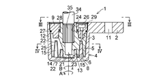
図1から図4において、本例の自動車シート用のダンパ1は、アーム部2及びハウジング本体3を一体的に有したハウジング4と、ハウジング本体3内にA及びB方向に回転自在に収容されていると共にハウジング本体3の内面5と協働して隙間6を形成する隙間形成部材7と、隙間6に配されたシリコン系未加硫ゴム8と、隙間形成部材7に固着された蓋体9とを具備している。
【0025】
アーム部2には連結用の貫通孔11が形成されており、ハウジング本体3は、円筒体12と、円筒体12の一端面を閉塞していると共に内面に中央凹部13が形成された閉塞部14と、閉塞部14の内面に中央凹部13を中心として設けられた同心の複数の円弧状の突部15とを一体的に有している。
【0026】
隙間形成部材7は、中央凹部13にA及びB方向に回転自在に嵌合された中央突部21と、ハウジング本体3の円弧状の突部15が隙間6をもって配されると共に、中央突部21を中心として設けられた同心の複数の円筒状の凹部22と、中央突部21に形成された中央凹部23と、中央凹部23に連通する孔24とを有しており、孔24において隙間形成部材7には軸方向に伸びるセレーション(凹凸)が形成されており、隙間形成部材7には、径方向に伸びると共に隙間6に連通した複数、本例では円周方向に等角度間隔に配された複数のスリット25が形成されている。
【0027】
30以上から420以下、好ましくは60以上から320以下、より好ましくは160以上から320以下の可塑度を有したシリコン系未加硫ゴム8は、隙間6に、ハウジング本体3及び隙間形成部材7に密に接して充填されてハウジング本体3内に配されている。
【0028】
蓋体9は、隙間形成部材7にねじ26により固着されており、蓋体9と隙間形成部材7との間及び蓋体9と円筒体12との間には、シール部材(Oリング)27及び28が嵌装されている。シリコン系未加硫ゴム8がそれ程流動性を有しない場合には、シールリング27及び28を省き得る。なお、蓋体9の円筒体12からの抜出しの防止は、円筒体12に嵌着されたEリング等のリング29により行われている。
【0029】
本例のダンパ1は、例えば自動車のシートとしてのリヤシート31のA及びB方向の回動と共に回動するシートフレーム32に、貫通孔11に挿入されたねじ又はピン33を介してアーム部2が連結され、リヤシート31のヒンジ機構(図示せず)の固定軸34のセレーション加工された先端部35及び最先端部36が孔24及び中央凹部23に嵌入されて、使用される。
【0030】
したがって、本例では、ハウジング4には、アーム部2を介してリヤシート31のA及びB方向の回動が伝達されるようになっており、隙間形成部材7は、リヤシート31が回動自在に設置されるシャーシ(車台)37に対して固定されるようになっている。リヤシート31に回動自在に連結された背もたれ38は、ヒンジ機構39によりリヤシート31に対してC及びD方向に回動自在になっている。
【0031】
シートフレーム32のA方向の回動は、公知のロック機構40により通常は禁止されており、シートフレーム32は、ロック機構40のロック解除で図6に示すようにA方向に回動できるようになっている。したがって、図5に示すように背もたれ38をC方向に回動後、図6に示すようにリヤシート31をA方向に回動することにより、大きな車内居住空間を確保することができる。
【0032】
斯かるダンパ1と、自動車のシャーシ37に対してA及びB方向に回動自在に設けられたシート、本例ではリヤシート31とを具備し、ハウジング4及び隙間形成部材7のうちの一方、本例ではハウジング4には、リヤシート31のA及びB方向の回動が伝達されるようになっており、ハウジング4及び隙間形成部材7のうちの他方、本例では隙間形成部材7は、シャーシ37に対して固定されている本例の自動車シートは、リヤシート31のA及びB方向の回動におけるアーム部2を介するハウジング本体3の隙間形成部材7に対する同じくA及びB方向の回動で、シリコン系未加硫ゴム8に変形を生じさせてリヤシート31の回転エネルギをシリコン系未加硫ゴム8の変形により吸収して回動時の衝撃を生じないようにでき、また例えば図6に示すようなリヤシート31が跳ね上げられた状態での急発進によるリヤシート31のB方向の戻りを緩衝できると共に、ロック機構40のアンロック時における急制動によるリヤシート31のA方向の跳ね上げを緩衝できる。
【0033】
そしてダンパ1によれば、シリコン系未加硫ゴム8でもって減衰機能を得るようにしているために、摩耗の虞もない上に、漏出防止のためのシールを省き得て、しかも、軽量且つ小型でも大きな減衰力を容易に得ることができ、その上、突部15と突部15が隙間6をもって配される凹部22とを有しているために、隙間6においてシリコン系未加硫ゴム8のハウジング本体3及び隙間形成部材7に接触する面積を大きくでき、而して、小型にしても大きなエネルギ吸収能を得ることができ、隙間形成部材7にスリット25が形成されているために、スリット25によりシリコン系未加硫ゴム8の隙間形成部材7に対する滑りを防止でき、しかも、シリコン系未加硫ゴム8の隙間6への充填に際しては斯かるスリット25を介してそれを行い得るから、隙間6ヘ確実に容易にシリコン系未加硫ゴム8を充填でき、シリコン系未加硫ゴム8とハウジング本体3及び隙間形成部材7との間にシリコン系未加硫ゴム8が充填されない隙間の生起をなくし得る。
【0034】
ところで、上記のダンパ1では、隙間形成部材7を固定する一方、ハウジング4をリヤシート31の回動と共に回転させるようにしたが、これに代えて、シャーシ37に取付け、固着されたブラケット54にねじ又はピン等でもってアーム部2を固着し、リヤシート31のヒンジ機構(図示せず)の固定軸34をリヤシート31のA及びB方向の回転と共に同方向に回転される回転軸とし、この回転軸のセレーション加工された先端部35及び最先端部36を隙間形成部材7の孔24及び中央凹部23に嵌入して、これより、ハウジング4を、リヤシート31が回動自在に設置されるシャーシ37に対してアーム部2を介して固定し、隙間形成部材7にリヤシート31の回動を伝達するようになっていてもよい。
【0035】
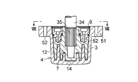
更に上記では、アーム部2及びハウジング本体3を一体的に有したハウジング4をもってダンパ1を構成したが、これに代えて、図7及び図8に示すように、環状の鍔部51及びハウジング本体3を一体的に有したハウジング4をもってダンパ1を構成してもよく、この場合には、固定用のねじ又はピン等が挿通される複数の貫通孔52を有した鍔部51は、ハウジング本体3の円筒体12に一体的に設けられている。
【0036】
図7及び図8に示すダンパ1でも、一端がシートフレーム32に固着された連結部材(図示せず)の他端に鍔部51をねじ又はピン等でもって固着し、これにより、ハウジング4に鍔部51を介してリヤシート31のA及びB方向の回動が伝達されるようになって、隙間形成部材7は、リヤシート31がA及びB方向に回動自在に設置されるシャーシ37に対して固定されるようになっていても、これに代えて、シャーシ37に取付け、固着されたブラケット54にねじ又はピン等でもって鍔部51を固着し、リヤシート31のヒンジ機構(図示せず)の固定軸34をリヤシート31のA及びB方向の回転と共に同方向に回転される回転軸とし、この回転軸のセレーション加工された先端部35及び最先端部36を隙間形成部材7の孔24及び中央凹部23に嵌入して、これより、ハウジング4は、リヤシート31がA及びB方向に回動自在に設置されるシャーシ37に対して鍔部51を介して固定されるようになって、隙間形成部材7にリヤシート31のA及びB方向の回動が伝達されるようになっていてもよい。
【0037】
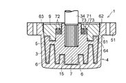
以上の例では、ねじ26より蓋体9を隙間形成部材7に固着したが、これに代えて、図9に示すように、外周面61に雄ねじ部62を有した蓋体9と、ハウジング本体3の内面5に雌ねじ部63を有したハウジング4とを用いて、雄ねじ部62を雌ねじ部63に螺合させて蓋体9をハウジング本体3に固着して、蓋体9をハウジング本体3と共に固定又は回転させるようにしてもよく、この場合には、蓋体9と隙間形成部材7との間にも隙間6に連通した隙間64を設けて、隙間64にもシリコン系未加硫ゴム8を充填すると、更に大きなエネルギ吸収能を得ることができる。また図9に示すダンパ1のように、隙間形成部材7の中央凹部23と固定軸34の最先端部36とを省いてもよく、加えて、シールリング27及び28を省いてシールリング27及び28の代わりに蓋体9と隙間形成部材7との間にラビリンス機構71を設けてもよい。
【0038】
詳細を図10に示す本例のラビリンス機構71は、隙間形成部材7に一体的に形成された同心の円筒状の複数の突起72と、蓋体9に設けられていると共に、各突起72が挿入される同心の複数の凹所73とを具備しており、突起72と凹所73とによりラビリンス74を形成しており、斯かるラビリンス74により蓋体9と隙間形成部材7との間からのシリコン系未加硫ゴム8の外部への漏洩を防止するようにしてもよい。
【0039】
また図11に示すように突起72の一つに環状の傾斜面75を設け、斯かる傾斜面75を蓋体9に当接させて、分断されたラビリンス76及び77をもってラビリンス機構71を構成してもよく、図11に示すラビリンス機構71によればシリコン系未加硫ゴム8の漏洩をより確実に防止できる。
【0040】
上記の例では、隙間形成部材7と別体の蓋体9を設けたが、これに代えて、図12に示すように蓋体9を省いてダンパ1を構成してもよい。この場合にも、上記の円筒体12に嵌着されたEリング等のリング29を用いて隙間形成部材7の円筒体12からの抜出しの防止を行ってもよいが、これに代えて、外周面81に雄ねじ部82を有した隙間形成部材7を用いて、雄ねじ部82をハウジング本体3の雌ねじ部63に螺合させて隙間形成部材7をハウジング本体3内にA及びB方向に回転自在に装着してもよく、この場合には、ハウジング本体3に対する隙間形成部材7のA及びB方向の相対的な回転で隙間形成部材7がハウジング本体3及び固定軸(又は回転軸)34に対して軸心方向、即ちE方向に相対的に移動可能になるように、E方向に関しても隙間形成部材7とハウジング本体3との間に、隙間6に連通してシリコン系未加硫ゴム8が同様に充填された隙間83を設ける一方、固定軸(又は回転軸)34の先端部35と孔24の底部との間にE方向の隙間84を設けると共に固定軸(又は回転軸)34の先端部35を隙間形成部材7の孔24内で隙間形成部材7に対してE方向に摺動可能とする。斯かる雄ねじ部82及び雌ねじ部63を用いた場合には、ハウジング本体3に対する隙間形成部材7のA及びB方向の相対的な回転でハウジング本体3に対して隙間83を含む隙間6の容積が変化するが、雄ねじ部82及び雌ねじ部63のねじピッチ寸法を極めて小さくすると、この容積変化は極めて僅かであって、シリコン系未加硫ゴム8の可圧縮性によってこれを吸収することができる。図12に示すダンパ1では、ハウジング本体3に対する隙間形成部材7のA及びB方向の相対的な回転でシリコン系未加硫ゴム8は捩り変形されることになる。
【0041】
【発明の効果】
本発明によれば、大きな減衰力を得ることができる上に小型にでき、特に背もたれを折り畳み、その後、シートを跳ね上げるようにした自動車シートに好適なダンパ及びこのダンパを具備した自動車シートを提供することができる。
【図面の簡単な説明】
【図1】本発明の好ましい実施の形態の一例の説明図である。
【図2】本発明の好ましい実施の形態の一例を示す断面説明図である。
【図3】図2に示す例のIII−III線矢視図である。
【図4】図2に示す例のIV−IV線矢視断面図である。
【図5】図1に示す例の動作説明図である。
【図6】図1に示す例の動作説明図である。
【図7】本発明の好ましい実施の形態の他の例を示す説明図である。
【図8】図7に示す例のVIII−VIII線矢視図である。
【図9】本発明の好ましい実施の形態の更に他の例を示す説明図である。
【図10】図9に示す例の一部拡大説明図である。
【図11】本発明の好ましい実施の形態の更に他の例の一部拡大説明図である。
【図12】本発明の好ましい実施の形態の更に他の例を示す説明図である。
【符号の説明】
1 ダンパ
2 アーム部
3 ハウジング本体
4 ハウジング
5 内面
6 隙間
7 隙間形成部材
8 シリコン系未加硫ゴム[0001]
BACKGROUND OF THE INVENTION
The present invention absorbs, for example, the rotational energy of a rear seat that is made to be freely rotatable (can be flipped up) in an automobile, and causes a sudden impact due to impact when the rear seat is flipped up or returned, or sudden braking when the rear seat is unlocked. The present invention relates to a damper for an automobile seat that can eliminate sudden jumping and a sudden return of the rear seat that is flipped up due to sudden acceleration, and an automobile seat equipped with the damper.
[0002]
[Problems to be solved by the invention]
As a damper for a backrest of an automobile seat, a damper using a fluid is known, but a damper using such a fluid must be large in order to obtain a large damping force, Requires a large seal to prevent leakage. In particular, in a vehicle seat damper in which the backrest is folded and then the seat is flipped up to secure a large interior space, it is necessary to attenuate the large rotational energy based on the backrest and the total load of the seat. In addition, it is difficult to obtain a desired large attenuation with a small damper simply using a fluid.
[0003]
The present invention has been made in view of the above-mentioned points, and the object of the present invention is to obtain a large damping force and to reduce the size, particularly to fold the backrest and then flip up the seat. Another object of the present invention is to provide a damper suitable for the automobile seat and an automobile seat provided with the damper.
[0004]
[Means for Solving the Problems]
A damper for an automobile seat according to a first aspect of the present invention includes a housing integrally having an arm portion and a housing body, and is rotatably accommodated in the housing body and cooperates with an inner surface of the housing body. A gap forming member for forming a gap and a silicon-based unvulcanized rubber disposed in the gap are provided. Here, the rotation of the seat of the automobile is transmitted to the housing via the arm portion. The gap forming member is fixed to a chassis on which an automobile seat is rotatably installed.
[0005]
A damper for an automobile seat according to a second aspect of the present invention includes a housing integrally having an arm portion and a housing body, and is rotatably accommodated in the housing body and cooperates with an inner surface of the housing body. A gap forming member for forming a gap and a silicon-based unvulcanized rubber disposed in the gap are provided. Here, the housing is an arm portion with respect to a chassis on which a seat of an automobile is rotatably installed. The rotation of the seat of the automobile is transmitted to the gap forming member.
[0006]
According to a third aspect of the present invention, there is provided a damper for an automobile seat, a housing integrally having a flange portion and a housing body, a housing that is rotatably accommodated in the housing body, and cooperates with an inner surface of the housing body. A gap forming member that forms a gap and a silicon-based unvulcanized rubber disposed in the gap are provided. Here, the rotation of the seat of the automobile is transmitted to the housing via the flange. The gap forming member is fixed to a chassis on which an automobile seat is rotatably installed.
[0007]
According to a fourth aspect of the present invention, there is provided a damper for an automobile seat, a housing integrally having a flange and a housing main body, a housing rotatably accommodated in the housing main body, and a cooperation with an inner surface of the housing main body. A gap forming member for forming a gap and a silicon-based unvulcanized rubber disposed in the gap are provided, and the housing is disposed via a flange portion with respect to a chassis on which a vehicle seat is rotatably installed. The rotation of the seat of the automobile is transmitted to the gap forming member.
[0008]
According to the dampers for automobile seats of the first to fourth aspects, since a damping function is obtained with the silicon-based unvulcanized rubber, there is no risk of wear, and a seal for preventing leakage In addition, it is possible to easily obtain a large damping force even with a light weight and a small size.
[0009]
The silicon-based unvulcanized rubber may have a plasticity of 30 or more and 420 or less, like the damper for automobile seats of the fifth aspect of the present invention. Having a plasticity of 60 or more and 320 or less, more preferably 160 or more like the damper for an automobile seat of the seventh aspect of the present invention. It has a plasticity of 320 or less.
[0010]
The plasticity in the present invention is a value measured with a William plasticity meter standardized by ASTM or the like. Specifically, the upper and lower parallel plates have a diameter of about 1.43 cm and a height of 1.27 cm. It is expressed by the height (mm / 100) of the silicon-based unvulcanized rubber after sandwiching a cylindrical shape with a volume of 2 cc and compressing with a load of 5 kg at 70-100 ° C. It is a thing.
[0011]
In the present invention, the silicon-based unvulcanized rubber has only to have a plasticity of 30 or more and 420 or less, as described above. The silicon-based unvulcanized rubber disposed in the gap between the main body and the gap forming member requires a sufficient seal for preventing leakage, and a large damping force cannot be expected. With the plasticity, the familiarity with the contact surface of the housing main body and the gap forming member is almost eliminated, and the housing main body and the gap are formed with respect to the silicon-based unvulcanized rubber in the relative rotation of the housing main body and the gap forming member. It becomes difficult to obtain a substantial damping force due to deformation of the silicon-based unvulcanized rubber due to slipping of the member, and in addition, the housing is in contact with the silicon-based unvulcanized rubber in order to prevent slipping. Even if the silicon-based unvulcanized rubber is gripped by using the surface of the main body and the gap forming member as an uneven surface, since the silicon-based unvulcanized rubber having a plasticity higher than 420 is extremely brittle, the housing main body and the gap forming member are relatively In a typical rotation, the silicon-based unvulcanized rubber is easily sheared (divided), and this also makes it impossible to obtain a damping force based on the deformation of the silicon-based unvulcanized rubber.
[0012]
The silicon-based unvulcanized rubber is filled in the gap between the housing body and the gap forming member. If the plasticity is greater than 420, there is no gap between the housing body and the gap forming member. It becomes extremely difficult to fill the silicon-based unvulcanized rubber, and after filling the silicon-based unvulcanized rubber, there is a gap between the housing body and the gap forming member and the silicon-based unvulcanized rubber. There is a possibility that desired attenuation cannot be obtained.
[0013]
In view of the necessity of such a seal and the magnitude of damping force obtained, conformability, brittleness, ease of filling, durability, and the like, the plasticity of the silicon-based unvulcanized rubber is preferably 60 as described above. From the above to 320 or less, more preferably from 160 to 320. When the plasticity is 60 or more, the fluidity of the silicon-based unvulcanized rubber is almost lost, and leakage of the silicon-based unvulcanized rubber can be prevented with a simple sealing mechanism. When the plasticity is 160 or more, the sealing mechanism Can be omitted, and a relatively large damping force can be obtained. On the other hand, when the plasticity of the silicon-based unvulcanized rubber is greater than 420, the compatibility with the contact surface of the housing body and the gap forming member is lost as described above, and the silicone-based unvulcanized rubber is easily fragile and sheared. However, in the case of silicon-based unvulcanized rubber having a plasticity of 320 or less, the compatibility with the contact surface of the housing body and the gap forming member is improved, and the relative rotation of the housing body and the gap forming member with respect to each other is improved. In this case, the silicone-based unvulcanized rubber is easily deformed without sliding so much against the contact surfaces of the housing body and the gap forming member, and the desired damping is easily obtained. Using a housing body and a gap forming member that are preferably plastically deformed according to the relative rotation of the forming member and formed an uneven surface for gripping the silicon-based unvulcanized rubber , It is possible to avoid a situation such as a silicon-based unvulcanized rubber is sheared so ragged.
[0014]
In the present invention, like the damper for an automobile seat according to the eighth aspect, the housing body has a plurality of concentric arc-shaped protrusions, and the gap forming member is an arc-shaped protrusion of the housing body. Has a plurality of concentric cylindrical recesses arranged with gaps.
[0015]
According to the damper for an automobile seat of the eighth aspect, it is possible to increase the area in contact with the housing body of the silicon-based unvulcanized rubber and the gap forming member in the gap, and thus further increase the energy absorption capacity even if the size is reduced. Can be obtained.
[0016]
In the present invention, preferably, like the damper for an automobile seat of the ninth aspect, the gap forming member is formed with a slit extending in the radial direction and communicating with the gap.
[0017]
According to the damper for automobile seats of the ninth aspect, since the silicon-based unvulcanized rubber can be filled into the slit communicating with the gap, the slit can prevent the silicon-based unvulcanized rubber from slipping against the gap forming member. In addition, when filling the gaps of the silicon-based unvulcanized rubber through the slits, it is possible to reliably fill the gaps with the silicon-based unvulcanized rubber. It is possible to eliminate the occurrence of a gap that is not filled with silicon-based unvulcanized rubber between the housing body and the gap forming member.
[0018]
In the present invention, at least one of the housing body and the gap forming member has an uneven surface in contact with the silicon-based unvulcanized rubber, and the uneven surface is a relative surface between the housing body and the gap forming member. The rotation of the silicon-based unvulcanized rubber in the vicinity of the uneven surface during rotation may be prevented from slipping on the uneven surface. The uneven surface may be embodied by discretely arranged protrusions or grooves, or continuous protrusions or grooves as described below, but may be embodied by a pear-like or wrinkled uneven surface.
[0019]
Such a concavo-convex surface functions to grip the silicon-based unvulcanized rubber in the vicinity of the concavo-convex surface, so that the relative rotation between the housing main body and the gap forming member causes the housing main body and the gap forming member and Slip between the vulcanized rubber can be prevented, the desired plastic deformation can be caused in the silicon-based unvulcanized rubber, and the target energy can be absorbed in the silicon-based unvulcanized rubber. As described above, the surfaces of the silicon-based unvulcanized rubber and the housing main body and the gap forming member in contact with the silicon-based unvulcanized rubber are well adapted, and no slip occurs between the housing main body and the gap forming member and the silicon-based unvulcanized rubber. In some cases or when slipping is allowed, a smooth surface may be used instead of the uneven surface.
[0020]
An automobile seat according to a first aspect of the present invention includes the damper according to any one of the above aspects, and a seat provided so as to be rotatable with respect to the chassis of the automobile. The rotation of the seat is transmitted to one of the members, and the other of the housing and the gap forming member is fixed to the chassis.
[0021]
According to the automobile seat of the first aspect, since the damping function is obtained with the silicon-based unvulcanized rubber, the effect of the damper can be obtained, and the seat, for example, the rear seat is splashed. It is possible to eliminate an impact at the time of raising or returning, a sudden jump due to sudden braking when the seat is unlocked, a sudden return due to sudden acceleration of the raised seat, and the like.
[0022]
Preferably, in the present invention, the seat is provided with a backrest that is pivotable like the automobile seat of the second aspect. In addition, the automobile seat of the present invention is not limited to such a seat provided with a backrest that can rotate freely, and the seat is not limited to a rear seat, and is another seat in an automobile. Also good.
[0023]
Next, the present invention and its embodiments will be described with reference to preferred examples shown in the drawings. The present invention is not limited to these examples.
[0024]
DETAILED DESCRIPTION OF THE INVENTION
1 to 4, a
[0025]
A connecting through-
[0026]
The
[0027]
The silicon-based
[0028]
The
[0029]
In the
[0030]
Therefore, in this example, the rotation of the
[0031]
The rotation of the
[0032]
Such a
[0033]
According to the
[0034]
By the way, in the
[0035]
Further, in the above, the
[0036]
Also in the
[0037]
In the above example, the
[0038]
The
[0039]
Further, as shown in FIG. 11, an annular
[0040]
In the above example, the
[0041]
【The invention's effect】
ADVANTAGE OF THE INVENTION According to the present invention, there is provided a damper suitable for an automobile seat that can obtain a large damping force and can be reduced in size, particularly folding a backrest and then flipping up the seat, and an automobile seat equipped with the damper. can do.
[Brief description of the drawings]
FIG. 1 is an explanatory diagram of an example of a preferred embodiment of the present invention.
FIG. 2 is a cross-sectional explanatory view showing an example of a preferred embodiment of the present invention.
FIG. 3 is a view taken along the line III-III of the example shown in FIG. 2;
4 is a cross-sectional view taken along the line IV-IV of the example shown in FIG.
FIG. 5 is an operation explanatory diagram of the example shown in FIG. 1;
6 is an operation explanatory diagram of the example shown in FIG. 1. FIG.
FIG. 7 is an explanatory diagram showing another example of a preferred embodiment of the present invention.
8 is a view taken along the line VIII-VIII of the example shown in FIG.
FIG. 9 is an explanatory diagram showing still another example of a preferred embodiment of the present invention.
10 is a partially enlarged explanatory view of the example shown in FIG. 9. FIG.
FIG. 11 is a partially enlarged explanatory view of still another example of the preferred embodiment of the present invention.
FIG. 12 is an explanatory diagram showing still another example of a preferred embodiment of the present invention.
[Explanation of symbols]
DESCRIPTION OF
Claims (11)
Priority Applications (8)
| Application Number | Priority Date | Filing Date | Title |
|---|---|---|---|
| JP2001130296A JP4352629B2 (en) | 2001-04-26 | 2001-04-26 | Damper for automobile seat and automobile seat equipped with this damper |
| DE60227862T DE60227862D1 (en) | 2001-02-14 | 2002-02-01 | Damper and motor vehicle seat with such a damper |
| EP02250709A EP1233206B1 (en) | 2001-02-14 | 2002-02-01 | Damper and automobile seat having the damper |
| KR1020020007686A KR100590278B1 (en) | 2001-02-14 | 2002-02-09 | Damper and automobile seat having the damper |
| CNB021046336A CN1321021C (en) | 2001-02-14 | 2002-02-10 | Damper and vehicle seat with the said damper |
| US10/074,235 US20020109386A1 (en) | 2001-02-14 | 2002-02-14 | Damper and automobile seat having the damper |
| US10/991,088 US7357230B2 (en) | 2001-02-14 | 2004-11-18 | Damper and automobile seat having the damper |
| US12/071,443 US7866451B2 (en) | 2001-02-14 | 2008-02-21 | Damper and automobile seat having the damper |
Applications Claiming Priority (1)
| Application Number | Priority Date | Filing Date | Title |
|---|---|---|---|
| JP2001130296A JP4352629B2 (en) | 2001-04-26 | 2001-04-26 | Damper for automobile seat and automobile seat equipped with this damper |
Publications (2)
| Publication Number | Publication Date |
|---|---|
| JP2002321553A JP2002321553A (en) | 2002-11-05 |
| JP4352629B2 true JP4352629B2 (en) | 2009-10-28 |
Family
ID=18978699
Family Applications (1)
| Application Number | Title | Priority Date | Filing Date |
|---|---|---|---|
| JP2001130296A Expired - Fee Related JP4352629B2 (en) | 2001-02-14 | 2001-04-26 | Damper for automobile seat and automobile seat equipped with this damper |
Country Status (1)
| Country | Link |
|---|---|
| JP (1) | JP4352629B2 (en) |
Families Citing this family (5)
| Publication number | Priority date | Publication date | Assignee | Title |
|---|---|---|---|---|
| CN1787930B (en) | 2003-05-12 | 2010-05-12 | 奥依列斯工业株式会社 | Damper for car seat and car seat mechanism having the damper |
| JP5486373B2 (en) * | 2010-03-29 | 2014-05-07 | テイ・エス テック株式会社 | Vehicle seat |
| KR101241027B1 (en) | 2011-07-06 | 2013-03-11 | (주) 미창케이블 | Apparatus of adjusting tilting angle of car back seat and rotary damper used therein |
| JP2016153687A (en) * | 2015-02-13 | 2016-08-25 | 日本電産サンキョー株式会社 | Fluid damper device, equipment with damper and process of manufacture of fluid damper device |
| JP2016148439A (en) * | 2015-02-13 | 2016-08-18 | 日本電産サンキョー株式会社 | Fluid damper device and apparatus with damper |
Family Cites Families (6)
| Publication number | Priority date | Publication date | Assignee | Title |
|---|---|---|---|---|
| JPS6124850A (en) * | 1984-07-16 | 1986-02-03 | Nifco Inc | One way damper |
| JPS62216847A (en) * | 1986-03-18 | 1987-09-24 | Nhk Spring Co Ltd | Foot brake |
| JPH02190634A (en) * | 1989-01-19 | 1990-07-26 | Fuji Seiki Co Ltd | Rotary damper |
| JP2519149Y2 (en) * | 1989-08-03 | 1996-12-04 | 株式会社ニフコ | Rotating damper |
| JPH0678704B2 (en) * | 1989-10-31 | 1994-10-05 | スガツネ工業株式会社 | Damper for door etc. |
| JPH05229411A (en) * | 1991-10-29 | 1993-09-07 | Oiles Ind Co Ltd | Unidirectional damper and pedal type parking brake for automobile using the damper |
-
2001
- 2001-04-26 JP JP2001130296A patent/JP4352629B2/en not_active Expired - Fee Related
Also Published As
| Publication number | Publication date |
|---|---|
| JP2002321553A (en) | 2002-11-05 |
Similar Documents
| Publication | Publication Date | Title |
|---|---|---|
| EP1233206B1 (en) | Damper and automobile seat having the damper | |
| JP4352629B2 (en) | Damper for automobile seat and automobile seat equipped with this damper | |
| US5460248A (en) | Brake device for damping a translatory motion | |
| KR20010082650A (en) | Rotary damper | |
| US7575390B2 (en) | Coupling device for a damper | |
| JP2019130956A (en) | Lid device | |
| US6594864B2 (en) | Cushioning device for rotatable components, such as, for example, roof grab handles or sun visors of a vehicle | |
| KR20210000458A (en) | Hinge Apparatus For Arm Rest | |
| KR101059966B1 (en) | Damper for car seat and car seat mechanism with this damper | |
| FR2657930A1 (en) | TWO-DISC CLUTCH. | |
| JP6976031B2 (en) | Slide rail including rotary damper | |
| JP4196566B2 (en) | Damper for automobile seat and automobile seat mechanism equipped with this damper | |
| JP5771949B2 (en) | Isolation damper pulley | |
| JP4352756B2 (en) | Damper for automobile seat and automobile seat mechanism equipped with this damper | |
| KR101241027B1 (en) | Apparatus of adjusting tilting angle of car back seat and rotary damper used therein | |
| JP4628616B2 (en) | Armrest | |
| JP6984134B2 (en) | Toilet seat unit | |
| EP1744926B1 (en) | Fuel cover for a motor vehicle | |
| JP4017698B2 (en) | Rotary damper | |
| JPH0849743A (en) | Damper and pedal type parking brake using this damper | |
| CN216279332U (en) | Interior division of handle assembly and vehicle | |
| JPS5842844A (en) | Damper | |
| JP3532890B2 (en) | Retractable assist grip | |
| JP4138055B2 (en) | One-way damper | |
| JP2005106277A (en) | Damper device |
Legal Events
| Date | Code | Title | Description |
|---|---|---|---|
| A621 | Written request for application examination |
Free format text: JAPANESE INTERMEDIATE CODE: A621 Effective date: 20080324 |
|
| TRDD | Decision of grant or rejection written | ||
| A01 | Written decision to grant a patent or to grant a registration (utility model) |
Free format text: JAPANESE INTERMEDIATE CODE: A01 Effective date: 20090707 |
|
| A01 | Written decision to grant a patent or to grant a registration (utility model) |
Free format text: JAPANESE INTERMEDIATE CODE: A01 |
|
| A61 | First payment of annual fees (during grant procedure) |
Free format text: JAPANESE INTERMEDIATE CODE: A61 Effective date: 20090720 |
|
| R150 | Certificate of patent or registration of utility model |
Ref document number: 4352629 Country of ref document: JP Free format text: JAPANESE INTERMEDIATE CODE: R150 Free format text: JAPANESE INTERMEDIATE CODE: R150 |
|
| FPAY | Renewal fee payment (event date is renewal date of database) |
Free format text: PAYMENT UNTIL: 20120807 Year of fee payment: 3 |
|
| FPAY | Renewal fee payment (event date is renewal date of database) |
Free format text: PAYMENT UNTIL: 20130807 Year of fee payment: 4 |
|
| R250 | Receipt of annual fees |
Free format text: JAPANESE INTERMEDIATE CODE: R250 |
|
| R250 | Receipt of annual fees |
Free format text: JAPANESE INTERMEDIATE CODE: R250 |
|
| R250 | Receipt of annual fees |
Free format text: JAPANESE INTERMEDIATE CODE: R250 |
|
| S531 | Written request for registration of change of domicile |
Free format text: JAPANESE INTERMEDIATE CODE: R313531 |
|
| R360 | Written notification for declining of transfer of rights |
Free format text: JAPANESE INTERMEDIATE CODE: R360 |
|
| R370 | Written measure of declining of transfer procedure |
Free format text: JAPANESE INTERMEDIATE CODE: R370 |
|
| S531 | Written request for registration of change of domicile |
Free format text: JAPANESE INTERMEDIATE CODE: R313531 |
|
| R350 | Written notification of registration of transfer |
Free format text: JAPANESE INTERMEDIATE CODE: R350 |
|
| R250 | Receipt of annual fees |
Free format text: JAPANESE INTERMEDIATE CODE: R250 |
|
| R250 | Receipt of annual fees |
Free format text: JAPANESE INTERMEDIATE CODE: R250 |
|
| R250 | Receipt of annual fees |
Free format text: JAPANESE INTERMEDIATE CODE: R250 |
|
| R250 | Receipt of annual fees |
Free format text: JAPANESE INTERMEDIATE CODE: R250 |
|
| LAPS | Cancellation because of no payment of annual fees |