JP4335540B2 - Game equipment - Google Patents
Game equipment Download PDFInfo
- Publication number
- JP4335540B2 JP4335540B2 JP2003004546A JP2003004546A JP4335540B2 JP 4335540 B2 JP4335540 B2 JP 4335540B2 JP 2003004546 A JP2003004546 A JP 2003004546A JP 2003004546 A JP2003004546 A JP 2003004546A JP 4335540 B2 JP4335540 B2 JP 4335540B2
- Authority
- JP
- Japan
- Prior art keywords
- banknote
- card
- unit
- control unit
- connector
- Prior art date
- Legal status (The legal status is an assumption and is not a legal conclusion. Google has not performed a legal analysis and makes no representation as to the accuracy of the status listed.)
- Expired - Fee Related
Links
Images


Description
【0001】
【発明の属する技術分野】
本発明は、遊技媒体としてのメダル払い出し装置を備えた台間メダル貸機が遊技機に隣接設置された遊技装置に関する。
【0002】
【従来の技術】
先行技術として、台間機には紙幣識別器を内蔵せずに紙幣識別器を外部設置方式とするように、メダル貸機やパチンコ玉貸機である台間機と遊技機が交互に背合わせで並設されて島を構成し、台間機の上部には紙幣識別器が設けられ、この紙幣識別器へ挿入され識別された紙幣を一方向へ搬送する紙幣搬送装置を島の内側の間隙に配置したものがある(例えば、特許文献1参照)。
【0003】
またパチンコやパチスロ等の遊技機間に装着される台間機に紙幣識別器が内蔵され、投入された紙幣をこの紙幣識別器で識別し、識別した真正紙幣を台間機内の収納部へ収納する方式とし、カード出し入れ口から投入された専用カードに投入金額を書き込み、書き込まれた金額から玉貸し金額を差し引く形態のものがある(例えば、特許文献2参照)。また台間機には、紙幣識別器が内蔵されておらずICカードへの金額情報の書き込み機能もないが、遊技島の端部に設置した販売機へ紙幣を投入して購入金額を選択することによりICカードを購入し、このICカードをパチンコ遊技機相互間に設置した台間機へ挿入して所定の取引を行うことによりパチンコ球を借りるものがある(例えば、特許文献3参照)。
【0004】
更に、台間メダル貸機がパチスロ機の横に併設されて島を構成した既存タイプがあって、この既存の台間メダル貸機の上に台間貸機用紙幣受入れ装置を設置すると共にこの台間貸機用紙幣受入れ装置の紙幣投入口へ投入された紙幣を搬送する搬送ラインを設置した搬送システム構成のものがある(例えば、特許文献4参照)。この特許文献4のものは、台間メダル貸機と台間貸機用紙幣受入れ装置の双方に紙幣投入口を設け、通常は、搬送システム側の台間貸機用紙幣受入れ装置の紙幣投入口へ紙幣を投入してメダル貸しを行うと共に搬送ラインによって紙幣を搬送するが、搬送システム側にトラブルが発生した場合には、切換えスイッチによって搬送システム側の紙幣識別検知手段からの払出信号を台間メダル貸機に内蔵した既設の紙幣識別検知手段からの払出信号に切り換えるものである。
【0005】
【特許文献1】
特開2001−232046号公報(第2頁〜第4頁、図1)
【特許文献2】
特開2002−000924号公報(第4頁、図1)
【特許文献3】
特開2000−342837号公報(第5頁〜第7頁、図1)
【特許文献4】
特開2001−162027号公報(段落番号0004〜0021、0030、図1〜図6)
【0006】
【発明が解決しようとする課題】
従来は、特許文献1のように、台間機の上部に紙幣識別器が設けられて、この紙幣識別器からの紙幣を一方向へ搬送する紙幣搬送装置を島の内側の間隙に配置したタイプのものと、特許文献2の台間機のように、紙幣識別器が内蔵されていて、カードへの金額の書き込みと書き込まれた金額から玉貸し金額を差し引く機能を備えたタイプとがそれぞれ存在するが、これら両タイプの台間機に共通の制御動作をするような電気回路構成の制御部を備える技術思想は存在せず、このため、従来は、夫々のタイプに専用の制御回路を構成して制御動作を行っている。
【0007】
また、特許文献4のものは、台間メダル貸機がパチスロ機の横に併設されて島を構成した既存タイプに、台間貸機用紙幣受入れ装置と搬送ラインとで構成する搬送システムタイプを付設するものであるため、この両タイプが一つの遊技島に設けられた状態である。この特許文献4のものは、両タイプを一つの遊技島に設けるためコストが嵩む問題がある。そして、切換えスイッチの切換え操作を忘れた場合や何らかが当たって切換えスイッチが元に戻った場合等には正常な動作が得られない問題も含む。
【0008】
投入された紙幣を紙幣識別器で識別し、その識別した真正紙幣の金額情報をカード挿入口から挿入されたICカードに書き込み、書き込まれた金額情報からメダル貸し金額を差し引くようにリーダライタを備えた台間機構成とし、この台間機からの情報を通信中継手段を介して集中管理システムとしてのホストコンピュータへ送信するシステムを組む場合、前記両タイプが共通の制御を行うようにすれば、個々の回路構成にする場合に比してコストが下がる。そして、一方のタイプの遊技装置を他方のタイプの遊技装置に変更する場合も、その変更に伴うコストが安くて済むことになる。
【0009】
また、特許文献4のように、台間メダル貸機がパチスロ機の横に併設されて島を構成した既存タイプと、台間貸機用紙幣受入れ装置と搬送ラインとで構成する搬送システムタイプとを一つの遊技島に付設しておくのではなく、一方のタイプのみを使用する方式とし、特許文献4のように切り換えスイッチによる方式ではなく、両タイプに共通の制御を行う制御回路に何れのタイプが設置されたかを判別できる回路を設けることによって、制御を安定的に行うことができるものとなる。
【0010】
本発明はこのような点に鑑みて、メダルの払い出し装置と、ICカードの利用のためのリーダライタを備えた台間機構成とし、紙幣識別装置が台間機に内蔵されたタイプと、紙幣識別装置が台間機の外に設置されていて紙幣搬送装置によって紙幣を搬送するタイプとに共通の制御ができる制御部をこのそれぞれのタイプの台間機に設けて前記両タイプに共通の制御が行えるようにし、この制御部に何れのタイプが接続されたかをこの制御部に印加する電圧によって判別できる回路を設けることによって、上記課題を解決するものである。
【0011】
【課題を解決するための手段】
本発明の遊技装置は、メダル払い出し装置を備えた台間メダル貸機が遊技機に隣接設置され、前記台間メダル貸機は、ICカードの受け入れ及び返却動作をするカード駆動装置と、紙幣識別装置からの金額情報をICカードに書き込みICカードの金額情報を読み出すリーダライタと、メダル払い出し部と、前記の紙幣識別装置、カード駆動装置、リーダライタ及びメダル払い出し部と電気的接続関係にある制御部とを備え、前記制御部は、前記台間メダル貸機内に紙幣識別装置が内蔵された内蔵タイプと前記台間メダル貸機外に設置された外部紙幣識別装置で識別した紙幣を紙幣搬送装置によって搬送する紙幣搬送タイプのいずれにも適応する構成であり、前記紙幣搬送タイプは前記制御部に対して前記外部紙幣識別装置がコネクタにて接続される構成であり、前記コネクタの接続によって前記制御部の回路電圧レベルを変更する回路を設け、前記制御部の回路電圧レベルが前記コネクタが接続されたときのレベルであるときには、前記制御部による前記外部紙幣識別装置の制御可能状態となり、前記制御部の回路電圧レベルが前記コネクタが接続されていないときのレベルであるときには、前記制御部による前記内蔵タイプの紙幣識別装置の制御可能状態となるように構成したことを特徴とする。
【0012】
これによって、紙幣識別装置と識別した真正紙幣を貯える収納部とを台間メダル貸機に内蔵する内蔵タイプの台間メダル貸機を使用する遊技装置においては、前記制御部によって内蔵した紙幣識別装置との動作が行われて、カード使用によるメダルの貸し出し供給が成立し、また前記紙幣搬送タイプを使用する遊技装置においては、紙幣識別装置が内蔵されていない台間メダル貸機を設置して、台間メダル貸機内の制御部へコネクタを接続することによって、紙幣搬送タイプの制御状態となる。このため、紙幣識別装置内蔵タイプの台間メダル貸機方式と、紙幣識別装置外部設置タイプの台間メダル貸機方式との何れが設置された遊技装置においても、紙幣識別装置との信号形態が共通であれば、制御部やリーダライタやメダル払い出し装置の制御を同じく行えるため、何れのタイプの遊技装置にも適用でき、製造とそれに伴うコストの面で大きな効果が期待できる。
【0013】
また、本発明の遊技装置では、前記回路電圧レベルを変更する回路は、前記コネクタが接続されないときにはハイレベル電圧又はローレベル電圧であり、前記コネクタの接続によってこの電圧とは異なるローレベル電圧又はハイレベル電圧へ接続するループバックケーブルを前記コネクタに備えたことを特徴とする。これによって、ループバックケーブルを介して、外部紙幣識別装置の電源がON状態でないときにも外部紙幣識別装置が接続されたことを判別回路が判別するため、制御部を外部紙幣識別装置と紙幣搬送部との通信状態に設定することが正確且つ容易となる。
【0014】
また、本発明の遊技装置において、前記紙幣搬送装置は、前記制御部に対して、前記外部紙幣識別装置との接続用の第1のコネクタとは別に設けられた第2のコネクタによって接続される構成であり、前記制御部の前記回路電圧レベルが前記第1のコネクタが接続されたときのレベルであるときには、前記第1のコネクタを介して前記制御部と前記外部紙幣識別装置との通信が行われると共に、前記第2のコネクタを介して前記制御部と前記紙幣搬送装置との通信が行われるように構成することができる。このように、紙幣搬送装置と外部紙幣識別装置との通信を別々の信号ラインによって行うようにしてもよい。
【0015】
【発明の実施の形態】
次に、本発明の実施の形態について説明する。各図は本発明の実施形態を示しており、図1は紙幣識別装置内蔵タイプの台間機を設置した遊技装置の島の正面図、図2は紙幣識別装置外部設置タイプの台間機を設置した遊技装置の島の正面図、図3は紙幣識別装置内蔵タイプの台間機の正面図、図4は紙幣識別装置外部設置タイプの台間機の正面図、図5は紙幣搬送装置の配置を示す遊技装置の平面図、図6は紙幣識別装置内蔵タイプの台間機を設置した遊技装置の制御回路構成図、図7は紙幣識別装置外部設置タイプの台間機を設置した遊技装置の制御回路構成図、図8は紙幣識別装置と紙幣搬送装置との配置構成の平面図、図9は紙幣搬送装置の一部正面図である。
【0016】
本発明を図に基づき説明する。先ず図1、図3及び図6において、1はパチスロ機やスロットマシン等のように遊技媒体にメダルを使用する遊技機である。2は遊技機1の横に隣接するように遊技機1相互間に配置される台間機であり、台間メダル貸機とも称し、遊技機1の横に隣接するように台間メダル貸機2が配置されて遊技装置Pの島を形成している。遊技機1と台間メダル貸機2は、遊技装置Pの島の外観形成を良好にするために、同一高さに形成されている。台間メダル貸機2は、上部に紙幣処理部10、下部にメダル払い出し部30、中間部にカード処理部20を内蔵している。紙幣処理部10は、前面に開口した紙幣挿入口11から挿入された紙幣100の真偽判別を行う紙幣識別装置12と、識別した真正紙幣を貯える紙幣収納部13を備えている。カード処理部20は、前面に開口したICカード挿入口21から挿入されたICカードの受け入れ及び返却動作をするカード駆動装置を備え、受け入れたICカードへ金額情報を書き込み、また書き込まれた金額情報やその他の情報を読み出すリーダライタ22と、使用済みICカードを収納するカード収納部23を備えている。メダル払い出し部30は、メダルを収納したメダル収納部31と、このメダル収納部31からメダルを取り出し口32またはメダル移送ノズル33へ送り出すメダル払い出し装置34を備えている。
【0017】
台間メダル貸機2は上記の他に、紙幣処理部10の前面には、紙幣識別装置12へ挿入するための紙幣挿入口11を備え、カード処理部20の前面には、テンキー、ICカードの返却スイッチ、メダル貸し出しスイッチ及びその他の機能スイッチを備えたキーボードスイッチ部24と表示部25とを備える。メダル収納部31へのメダルの補給は、前面板35を開くことにより上面開口のメダル収納部31へのメダルの補給が可能である。カード収納部23へ収納されたカードは、前面板26を開いて取り出し可能である。メダル払い出し装置34は、メダル収納部31の下端部において、電動機機構によって回転する払い出し盤の回転によって、メダル収納部31のメダルを1枚ずつ払い出す仕組みである。
【0018】
台間メダル貸機2に適用可能な紙幣100は、例えば、1000円、2000円、5000円、10000円の紙幣である。
【0019】
図6に示すように、台間メダル貸機2の内部には、紙幣処理部10、カード処理部20、及びメダル払い出し部30へ信号を送り又は信号を受け取るようにこれらと電気的に接続された制御部40を備えている。制御部40は特定の判別回路41を備え、判別回路41の基準電圧ライン42には、電源電圧のプラス電圧(ハイレベル電圧)であるVccが印加されている。この判別回路41の状態は、制御部40が紙幣処理部10との信号の授受を行うことができる状態を表している。なお、判別回路41の動作によっては、この基準電圧ライン42へアース電圧(ローレベル電圧)が印加された状態とすることもできる。
【0020】
このように判別回路41によって制御部40が紙幣処理部10との信号の授受を行う状態において、通常、顧客はICカードをICカード挿入口21へ挿入してから紙幣挿入口11へ紙幣を挿入する。挿入された紙幣100が紙幣識別装置12に設けた紙幣移送装置によって識別部へ送られて識別される。ここで真正紙幣であると判別されたときには、紙幣処理部10から制御部40へその金額情報(価値情報ともいう)が送信され、制御部40はこの金額情報をリーダライタ22によってICカードへ書き込むよう制御する。これと共に制御部40は紙幣処理部10へ紙幣取り込み信号を発して、紙幣識別装置12に設けた紙幣移送装置を駆動して紙幣を紙幣収納部13へ移送する。若し偽紙幣の場合には、前記紙幣移送装置によって紙幣挿入口11へ返却される。ICカードへ書き込まれた合計金額は、表示部25に表示される。
【0021】
上記のようにICカードへの金額情報の書き込みが行われた後、前記のメダル貸し出しスイッチが押されると、メダル払い出し部30へ信号を送り、メダル払い出し装置34を作動させて、メダル収納部31から1回に貸し出される所定枚数のメダルを取り出し口32またはメダル移送ノズル33へ送り出す。
【0022】
このメダルの払い出し動作と共に制御部40は、この払い出した貸し出しメダルに相当する金額情報(価値情報ともいう)を減算させるための信号をリーダライタ22へ送信して、この減算した残額の金額情報をリーダライタ22によってICカードに書き込むよう制御する。ICカードの残額は、表示部25に表示される。カード処理部20は、リーダライタ22によってICカードに書き込まれた情報を台間メダル貸機2の外に設けた通信中継装置45を介して集中管理システムとして設けた遊技施設内のホストコンピュータへ送信し、各種の情報管理が行われる。
【0023】
このように、制御部40によって紙幣処理部10、カード処理部20、及びメダル払い出し部30が所定の動作をする。ICカードは、遊技装置Pが設置されたその遊技施設に登録した顧客に対して、又は一見顧客に対して発行するものである。一見顧客の場合は、その遊技施設から一見顧客用ICカードの貸与を受けて、このICカードをICカード挿入口21へ挿入してから紙幣挿入口11へ紙幣を挿入することにより、上記のようにメダルの払い出し動作が行われる。この一見顧客用ICカードには、その日限りの使用のみである情報が記憶されており、このICカードを持ち帰って翌日使用することはできないようになっている。
【0024】
一見顧客は、ICカードの残額が少なくなったときには、紙幣挿入口11へ紙幣を追加挿入することにより、ICカードにその金額情報が書き込まれると共に合計金額が表示部25に表示される。この場合も上記同様にメダルの払い出しを行うことができる。そして、遊技終了後は、ICカードの返却スイッチボタンを押すことによって制御部40からの指令に基づき、リーダライタ22に備えたカード駆動装置の動作によってICカードがICカード挿入口21へ返却される。なお、このICカードを遊技施設に設けた清算機にて残額の返却清算ができる。また、一見顧客の場合には、ICカードの返却スイッチを押したとき、ICカードに書き込まれた金額を使い切った状態であれば、制御部40からの指令によってリーダライタ22に備えたカード駆動装置の動作によって使用済みカードとしてカード収納部23へ取り込まれる。
【0025】
一方、登録した顧客は、遊技施設から登録顧客用ICカードの貸与を受けて、このICカードをICカード挿入口21へ挿入してから紙幣挿入口11へ紙幣を挿入することにより、ICカードへの金額情報の書き込まれ、その書き込みが行われた後に前記のメダル貸し出しスイッチが押されると、メダル払い出し部30へ信号を送り、メダル払い出し装置34を作動させて、メダル収納部31から1回に貸し出される所定枚数のメダルを取り出し口32またはメダル移送ノズル33へ送り出す。ICカードの残額が少なくなったときには、紙幣挿入口11へ紙幣を追加挿入することによりICカードにその金額情報が書き込まれ、その合計金額が表示部25に表示される。この場合も上記同様にメダルの払い出しを行うことができる。
【0026】
このICカードは、翌日使用することもできるようにするための情報が記憶されており、登録した顧客の利便を図っている。したがって、ICカードの返却スイッチを押すことによってICカードはICカード挿入口21へ返却され、翌日このICカードを使用できる。翌日このICカードをICカード挿入口21へ挿入して表示部25の表示が残額を示す場合、その残額が遊技装置Pに設定された1回のメダル払い出し枚数以上であれば、前記のメダル貸し出しスイッチが押されると上記同様に所定枚数のメダルが払い出される。なお、このICカードを遊技施設に設けた清算機に挿入することによって、残額の返却清算ができる。
【0027】
上記は、紙幣識別装置内蔵タイプの台間機2が設けられた遊技装置Pに関するものである。次に紙幣識別装置外部設置タイプの台間機を設置した遊技装置Pについて、図2、図4、図5及び図7〜図9に基づき説明する。
【0028】
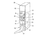
図2、図4、図5及び図7〜図9において、図1、図3及び図6のものと同符号の部分は同一部分を示すものである。この方式において、遊技機1の横に隣接するように遊技機1相互間に台間機(台間メダル貸機ともいう)2Aが配置されて遊技装置Pの島を形成している。遊技機1と台間メダル貸機2Aは、遊技装置Pの島の外観形成を良好にするために、同一高さに形成されている。台間メダル貸機2Aは、紙幣識別装置と紙幣収納部を内蔵せず、紙幣識別装置が外部設置タイプである。この外部設置の紙幣識別装置を符号80で示す。台間メダル貸機2Aは、台間メダル貸機2と同様に、下部にメダル払い出し部30、中間部にカード処理部20を備えているが、上部は空間であり前面を化粧板60でカバーしている。
【0029】
外部紙幣識別装置80は、顧客の使用性を考慮して台間メダル貸機2Aの上に載置される。台間メダル貸機2Aが外部設置タイプであるため、紙幣識別装置80で識別された真正紙幣100は、紙幣識別装置80の背面側に遊技装置Pに沿って配置した紙幣搬送装置5Bによって、金庫に相当する紙幣収納部Kへ向けて搬送される。
【0030】
紙幣搬送部5は、紙幣搬送制御装置5Aと外部紙幣搬送装置5Bとを備え、外部紙幣識別装置80で識別した真正紙幣100を紙幣搬送装置5Bによって所定の場所へ搬送制御する。紙幣搬送装置5Bは、図8に示すように、中継搬送装置4の複数と、紙幣識別装置80の識別部Sで識別された真正紙幣100を中継搬送装置4に合流させる合流装置3の複数とが、交互に配置された組み合わせによって構成されている。中継搬送装置4は、紙幣100の入口側6と出口側7にそれぞれ一対ずつ設けた回転子8、9に掛け渡された所定幅の一対のベルト110、111によって、紙幣100をその厚さ方向の両側から挟持して横長に立てた状態で搬送する搬送路12を形成している。
【0031】
合流装置3は、上流側の中継搬送装置4から搬送されてくる紙幣100を、その厚さ方向の両側から挟持して横長に立てた状態で下流側の中継搬送装置4へ搬送するための一対の回転子50と、紙幣識別装置80の識別部Sで識別された真正紙幣100を、横長に立てた状態で下流側の中継搬送装置4へ搬送するための回転子51とを備えている。回転子51は、外周面に突出した合成樹脂製の多数の弾性突起を備え、識別部Sで識別された真正紙幣100をこの突起によってカーブした通路に沿って横長に立てた状態で下流に向けて送り出す作用をする。回転子50、51は、共通の電動機要素53によって歯車59A、59B等を介して駆動される。
【0032】
紙幣識別装置80は、横長に立てた状態で挿入された紙幣100を識別部Sで識別するように、そして、識別した真正紙幣100をその厚さ方向の両側から挟持して横長に立てた状態で合流装置3へ搬送するために、入口側と出口側にそれぞれ設けた一対の回転子60、61によって駆動される一対のベルト62、63を備えている。回転子60、61のいずれか一方は、電動機要素60Aによって駆動される。
【0033】
合流装置3には、電動機要素53と、回転子50、51と、回転子50、51を駆動する各種歯車59A、59B等と、中継搬送装置4の回転子8の軸に取り付けた歯車57に駆動力を伝達する歯車55、56等を備えている。これによって、歯車55と57が噛み合うように、中継搬送装置4の前後端部を合流装置3の前後に張り出した支持部180に載置すると共に、案内部115を合流装置3の入口に挿入状態に組み合わせ、この状態で中継搬送装置4の上端部に張り出した取り付け辺181に形成した孔に合流装置3の上面の突起182を嵌め合わせる。
【0034】
これによって歯車55と57が噛み合い、電動機要素53によって、合流装置3の回転子50、51と、中継搬送装置4の一対のベルト110、111が同期して駆動される。なお、歯車55と57との噛み合い保持の更なる確保のために、必要に応じて中継搬送装置4の入口側と合流装置3をネジ結合してもよい。中継搬送装置4の案内部15は合流装置3の入口に挿入状態に組み合わされるため、中継搬送装置4の出口側と合流装置3の入口との間隔の長短が生じても、それはこの案内部15が合流装置3の入口に入り込む深さの度合いによって吸収でき、紙幣の搬送には支障がない。
【0035】
各紙幣識別装置80の識別部Sで識別された真正紙幣100が、紙幣搬送装置5Bへ移送されて詰まりなく搬送されるためには、紙幣100が合流装置3から中継搬送装置4へ移送されるとき、その上流の中継搬送装置4から搬送される紙幣と衝突しない制御が必要である。このため、各中継搬送装置4には、一対のベルト110、111によって搬送される紙幣100の存在を検知するセンサ210を設けている。
【0036】
これによって、いま、或る一つの合流装置3(これを3Aとする)の入口に連結された上流側の中継搬送装置4に搬送されている紙幣100が存在しているときには、センサ210がそれをキャッチして、この一つの合流装置3Aに対応する紙幣識別装置80の電動機要素60Aを停止状態に制御して、この合流装置3Aに対応する紙幣識別装置80から紙幣100が合流装置3Aへ移送されないようにする。そして、この停止期間中に、この中継搬送装置4で搬送されている紙幣100を合流装置3Aを通してその下流側の中継搬送装置4へ移送し、この下流側の中継搬送装置4のセンサ210が移送された紙幣100を検知したとき、紙幣搬送要求信号が制御部40から紙幣搬送部5の紙幣搬送制御装置5Aへ発せられ、紙幣搬送部5の紙幣搬送制御装置5Aからの紙幣取り込み許可信号が制御部40へ発せられ、制御部40は紙幣取り込み信号を紙幣識別装置80へ発して、前記停止していた電動機要素60Aを再始動して、紙幣識別装置80に留まっていた紙幣100を合流装置3Aへ移送するように制御する。
【0037】
このような制御のために、制御部40に対して紙幣識別装置80が電気的接続手段によって接続され、制御部40は、この電気的接続手段によって紙幣搬送部5と通信可能状態となるよう制御部の回路電圧レベルを変更する回路を備えている。実施形態では、この電気的接続手段をコネクタとし、このコネクタに制御部40の判別回路41の回路電圧レベルを変更する回路を設けている。実施形態では、紙幣搬送装置5Bに対応して紙幣搬送制御装置5Aを設けている。この紙幣搬送制御装置5Aは、センサ210の信号を受ける信号ラインと、電動機要素53及び60Aの動作を制御する電気回路等含み、台間メダル貸機2Aの固定側コネクタ43Aに対して着脱可能に接続されるコネクタ90でもって制御部40へ接続されていて、制御部40からの信号によって動作する構成である。このコネクタ43Aと90が前記電気的接続手段を構成する。また紙幣識別装置80は、台間メダル貸機2Aの固定側コネクタ43に対して着脱可能に接続されるコネクタ92でもって制御部40へ電気的に接続される。
【0038】
制御部40は判別回路41を備え、判別回路41は、その入力電圧の大きさによって出力「有」(これを出力「1」の状態という)か「無」(これを出力「0」の状態という)かの動作をする。その一つの方式として、判別回路41は二つの入力端子を備え、その一方の入力端子には閾値電圧が印加されていて、他方の入力端子に加える電圧がその閾値電圧未満又は以下の場合は出力が「0」、閾値電圧以上又は越えた場合に出力が「1」となる動作をする構成がある。コネクタ92によって、紙幣識別装置80は制御部40と信号ライン93が形成されると共に、コネクタ92に設けたループバックケーブル94によって、判別回路41の前記他方の入力端子の電圧ライン42は制御部40のアース電圧ライン95に接続される。このループバックケーブル94によって、判別回路41の入力電圧ライン42は、プラス電圧(ハイレベル電圧)であるVccからアース電圧(ローレベル電圧)へ切り換わる。即ち、判別回路41の入力電圧ライン42は、出力「1」から「0」へ切り換わり、制御部40は紙幣識別装置80が接続された状態となる。
【0039】
なお、前述のように図6に示す紙幣識別装置内蔵タイプの台間メダル貸機2において、基準電圧ライン42へアース電圧(ローレベル電圧)が印加された状態に設定している場合には、図7に示すような紙幣識別装置が外部設置タイプの台間メダル貸機2Aにおいては、このループバックケーブル94によって、判別回路41の基準電圧ライン42をプラス電圧(ハイレベル電圧)であるVccとする方式とすることもできる。上記の構成に代わって、判別回路41の電圧ライン42が、判別回路41の電源電圧ライン42の電圧であり、これを所定のプラス電圧(ハイレベル電圧)であるVccとして判別回路41を動作状態とするか、ゼロ電圧であるアース電圧として判別回路41を不動作状態とするかをループバックケーブル94によって行う方式でもよい。
【0040】
このように、コネクタ92を台間メダル貸機2Aに設けたコネクタ43へ接続することによって、紙幣識別装置80との信号ライン93が形成されると共に、判別回路41の電圧ライン42の回路電圧が変わるため、判別回路41の状態によって、制御部40は紙幣識別装置80有りの信号を検出した状態である。この検出状態において、制御部40は、コネクタ90でもって紙幣搬送制御装置5Aとの間に形成される信号ライン91によって、紙幣搬送制御装置5Aと通信可能となる。
【0041】
カード処理部20は、リーダライタ22によってICカードに書き込まれた情報を台間メダル貸機2の外に設けた通信中継装置45を介して集中管理システムとして設けた遊技施設内のホストコンピュータへ送信し、各種の情報管理が行われる。
【0042】
台間メダル貸機2、2Aとも部品の共通した製造を行うためには、台間メダル貸機2の背面に固定側コネクタ43、43Aを設け、この固定側コネクタ43の一つの端子に、制御部40の判別回路41の電圧ライン42を接続した形態とすることによって、更に好ましい形態となる。この一つの端子は、固定側コネクタ43へコネクタ92が接続されない限り開放状態である。このように構成することによって、台間メダル貸機2の形態から紙幣識別部10を取り外した形態が台間メダル貸機2Aとなるため、両形態の台間メダル貸機2、2Aの殆んどの部分を同じ製造ラインによって製造できるため、製造コストの低下となる。
【0043】
なお、台間メダル貸機2Aの固定側コネクタ43、43Aを単一のコネクタ構成とすることもできる。また、コネクタ90、92を単一のコネクタ構成とすることもできる。
【0044】
図7において、動作を説明する。上記のように、コネクタ92を台間メダル貸機2Aに設けたコネクタ43へ接続することによって、紙幣識別装置80との信号ライン93が形成されると共に、判別回路41の電圧ライン42の電圧がアース電圧ライン95の電圧、即ち、アース電圧に変わり、制御部40は紙幣識別装置80「有り」の信号を検出した状態である。
【0045】
この状態において、顧客はICカードを台間メダル貸機2AのICカード挿入口21へ挿入し、紙幣識別装置80の紙幣挿入口へ紙幣を挿入する。挿入された紙幣100が紙幣識別装置80に設けたベルト62、63を含む紙幣移送装置によって識別部Sへ送られて識別される。ここで真正紙幣であると判別されたときには、識別部Sから制御部40へその金額情報(価値情報ともいう)が送信されると共に、制御部40は、この金額情報をリーダライタ22によってICカードへ書き込むよう制御する。若し偽紙幣の場合には、前記紙幣移送装置によって紙幣挿入口へ返却される。
【0046】
上記のように、ICカードへの金額情報の書き込み後に前記のメダル貸し出しスイッチが押されると、メダル払い出し部30へ信号を送り、メダル払い出し装置34を作動させて、メダル収納部31から1回に貸し出される所定枚数のメダルを取り出し口32またはメダル移送ノズル33へ送り出す。また、制御部40は、上述のように、紙幣搬送部5、即ち紙幣搬送制御装置5Aからの紙幣取り込み許可信号に基づき、紙幣取り込み信号を紙幣識別装置80へ発して、紙幣100は合流装置3へ送り出される。合流装置3へ送り出された紙幣100は、中継搬送装置4へ移送されて最終的には、紙幣収納部Kへ収納される。
【0047】
このメダルの払い出し動作と共に制御部40は、この払い出した貸し出しメダルに相当する金額情報(価値情報ともいう)を減算させるための信号をリーダライタ22へ送信して、この減算した残額の金額情報をリーダライタ22によってICカードに書き込むよう制御し、その残額が表示部25に表示される。カード処理部20は、リーダライタ22によってICカードに書き込まれた情報を台間メダル貸機2Aの外に設けた通信中継装置45を介して集中管理システムとして設けた遊技施設内のホストコンピュータへ送信し、各種の情報管理が行われる。
【0048】
このように、制御部40によって紙幣識別装置80、紙幣搬送部5、カード処理部20、及びメダル払い出し部30が所定の動作をする。ICカードは、遊技装置Pが設置されたその遊技施設に登録した顧客に対して、又は、一見顧客に対して発行するものである。上記同様に、一見顧客の場合は、その遊技施設から一見顧客用ICカードの貸与を受けて、このICカードをICカード挿入口21へ挿入してから紙幣挿入口11へ紙幣を挿入することにより、上記のようにメダルの払い出し動作が行われる。ICカードの残額が少なくなったときには、紙幣識別装置80の紙幣挿入口へ紙幣を追加挿入することにより、ICカードにその金額情報が書き込まれる。このICカードには、その日限りの使用のみである情報が記憶されており、このICカードを持ち帰って翌日使用することはできないようになっている。また、一見顧客の場合には、ICカードの返却スイッチを押したとき、ICカードに書き込まれた金額を使い切った状態であれば、制御部40からの指令によってリーダライタ22に備えたカード駆動装置の動作によって使用済みカードとしてカード収納部23へ取り込まれる。
【0049】
一方、登録した顧客は、遊技施設から登録顧客用ICカードの貸与を受けて、このICカードをICカード挿入口21へ挿入し、紙幣識別装置80の紙幣挿入口へ紙幣を挿入することにより、ICカードにその金額情報が書き込まれ、上記同様に前記のメダル貸し出しスイッチが押されると、所定枚数のメダルが払い出される。ICカードの残額が少なくなったときには、紙幣識別装置80へ紙幣を追加挿入することによりICカードにその金額情報が書き込まれ、上記同様に前記のメダル貸し出しスイッチが押されると、所定枚数のメダルが払い出される。このICカードは、翌日使用することもできるようにするための情報が記憶されており、登録した顧客の利便を図っている。したがって、翌日このICカードをICカード挿入口21へ挿入して表示部25の表示が残額を示す場合、前記のメダル貸し出しスイッチが押されると、上記同様に、所定枚数のメダルが払い出される。
【0050】
上記のように、本発明における台間メダル貸機は、紙幣識別装置12とこの紙幣識別装置12で識別した真正紙幣100を貯える収納部13とを内蔵する内蔵タイプの台間メダル貸機2と、外部紙幣識別装置80とこの外部紙幣識別装置80で識別した真正紙幣100を所定の場所へ搬送する紙幣搬送装置5とを台間メダル貸機2A外に設ける紙幣搬送タイプの台間メダル貸機2Aの何れかであって、前記何れの台間メダル貸機2、2Aとも、ICカードの受け入れ及び返却動作をするカード駆動装置と、紙幣識別装置からの金額情報をICカードに書き込みICカードの金額情報を読み出すリーダライタ22と、メダル払い出し部30と、前記の紙幣識別装置12又は80、カード駆動装置、リーダライタ22及びメダル払い出し部30と電気的接続関係にある制御部40とを備え、制御部40は、コネクタ92の接続の有無によって紙幣搬送部5との通信可能状態か内蔵タイプの台間メダル貸機2の制御状態かになるよう、制御部40の判別回路41の回路電圧レベルを変更する回路をコネクタ92に備えたものである。これによって、着脱式コネクタ92が接続されないときには、内蔵タイプの台間メダル貸機2の紙幣識別装置12の制御可能状態となり、また、着脱式コネクタ92の接続によって、搬送制御装置5Aと外部紙幣識別装置80との制御状態となるよう制御部40の判別回路41の回路電圧レベルを変更する。
【0051】
これによって、紙幣搬送タイプを使用する遊技装置においては、紙幣識別装置が内蔵されていない台間メダル貸機2Aを設置して、台間メダル貸機2A内の制御部40へコネクタ92を接続することによって、紙幣搬送タイプの制御状態となる。このため、紙幣識別装置内蔵タイプの台間メダル貸機方式と、紙幣識別装置外部設置タイプの台間メダル貸機方式との何れが設置された遊技装置においても、紙幣識別装置との信号形態が共通であれば、制御部40やリーダライタ22やメダル払い出し部30の制御を同じく行えるため、何れのタイプの遊技装置にも適用でき、製造とそれに伴うコストの面で大きな効果が期待できる。
【0052】
そして、制御部40の回路電圧レベルを変更する装置は、着脱式コネクタ92の接続によって、制御部40の動作電圧レベルをハイレベル電圧またはローレベル電圧へ接続するループバックケーブル94によって構成されている。これによって、外部紙幣識別装置80の電源がON状態でないときにも、外部紙幣識別装置80が接続されたことを判別回路41が判別するため、主制御部40を外部紙幣識別装置80と紙幣搬送部5との通信状態に設定することが正確且つ容易となる。
【0053】
本発明は、上記実施形態に限定されず、本発明の技術的範囲を逸脱しない限り種種の変更が考えられ、それに係る種種の実施形態を包含するものである。
【0054】
【発明の効果】
本発明によって、紙幣搬送タイプを使用する遊技装置においては、紙幣識別装置が内蔵されていない台間メダル貸機を設置して、台間メダル貸機内の制御部へコネクタを接続することによって、紙幣搬送タイプの制御状態となる。このため、紙幣識別装置内蔵タイプの台間メダル貸機方式と、紙幣識別装置外部設置タイプの台間メダル貸機方式との何れが設置された遊技装置においても、紙幣識別装置との信号形態が共通であれば、制御部やリーダライタやメダル払い出し部の制御を同じく行えるため、何れのタイプの遊技装置にも適用でき、製造とそれに伴うコストの面で大きな効果が期待できる。
【0055】
また、制御部の回路電圧レベルを変更する装置は、コネクタの接続によって制御部の動作電圧レベルをハイレベル電圧又はローレベル電圧へ接続するループバックケーブルによって構成しており、外部紙幣識別装置の電源がON状態でないときにも、外部紙幣識別装置が接続されたことを判別回路が判別するため、制御部を外部紙幣識別装置と紙幣搬送部との通信状態に設定することが正確且つ容易となる。
【図面の簡単な説明】
【図1】本発明に係る紙幣識別装置内蔵タイプの台間機を設置した遊技装置の島の正面図である。
【図2】本発明に係る紙幣識別装置外部設置タイプの台間機を設置した遊技装置の島の正面図である。
【図3】本発明に係る紙幣識別装置内蔵タイプの台間機の正面斜視図である。
【図4】本発明に係る紙幣識別装置外部設置タイプの台間機の正面斜視図である。
【図5】本発明に係る紙幣搬送装置の配置を示す遊技装置の平面図である。
【図6】本発明に係る紙幣識別装置内蔵タイプの台間機を設置した遊技装置の制御回路構成図である。
【図7】本発明に係る紙幣識別装置外部設置タイプの台間機を設置した遊技装置の制御回路構成図である。
【図8】本発明に係る紙幣識別装置と紙幣搬送装置との配置構成の平面図である。
【図9】本発明に係る紙幣搬送装置の一部正面図である。
【符号の説明】
1・・・遊技機
2・・・紙幣識別装置内蔵式台間メダル貸機
2A・・・紙幣搬送式台間メダル貸機
3、3A・・・合流装置
4・・・中継搬送装置
5・・・紙幣搬送部
5A・・・紙幣搬送制御装置
5B・・・紙幣搬送装置
10・・・紙幣処理部
11・・紙幣挿入口
12・・紙幣識別装置
13・・紙幣収納部
20・・カード処理部
21・・ICカード挿入口
22・・リーダライタ
30・・メダル払い出し部
34・・メダル払い出し装置
40・・制御部
41・・判別回路
42・・基準電圧ライン
80・・外部紙幣識別装置
90、92・・コネクタ
94・・ループバックケーブル
100・・紙幣[0001]
BACKGROUND OF THE INVENTION
The present invention relates to a gaming machine in which an inter-unit medal lending machine provided with a medal payout device as a gaming medium is installed adjacent to a gaming machine.
[0002]
[Prior art]
As a prior art, the bill machine and pachinko ball lending machine are back-to-back alternately so that the bill discriminator is not installed in the bill machine and the bill discriminator is installed externally. Are arranged side by side to form an island, and a bill discriminator is provided on the upper part of the interstage machine. (For example, refer to Patent Document 1).
[0003]
In addition, a bill discriminator is built in a machine between pachinko and pachislot machines, and the inserted bill is discriminated by this bill discriminator, and the identified authentic bill is stored in the storage unit in the machine. There is a method in which the inserted amount is written in a dedicated card inserted from the card slot, and the ball lending amount is subtracted from the written amount (see, for example, Patent Document 2). In addition, the interbank machine does not have a built-in bill discriminator and does not have a function to write money amount information to the IC card. However, the bill is inserted into the vending machine installed at the end of the amusement island and the purchase amount is selected. In some cases, an IC card is purchased, and a pachinko ball is borrowed by inserting the IC card into a table machine installed between pachinko gaming machines and performing a predetermined transaction (for example, see Patent Document 3).
[0004]
In addition, there is an existing type in which an intermediary medal lending machine is installed next to the pachislot machine to form an island, and a bill accepting device for an intermediary lending machine is installed on this existing intermediary medal lending machine. There exists the thing of the conveyance system structure which installed the conveyance line which conveys the banknote thrown into the banknote insertion slot of the banknote acceptance apparatus for interbank lending machines (for example, refer patent document 4). In this patent document 4, a bill insertion slot is provided in both the inter-unit medal lending machine and the inter-lending machine banknote acceptance device, and usually the banknote insertion port of the inter-lending machine banknote acceptance device on the transport system side. The banknotes are thrown in and the banknotes are transported by the transport line. If trouble occurs on the transport system side, the changeover switch sends the payout signal from the banknote identification detection means on the transport system side. It switches to the payout signal from the existing banknote identification detection means built in the medal lending machine.
[0005]
[Patent Document 1]
Japanese Patent Laid-Open No. 2001-232046 (
[Patent Document 2]
JP 2002-000924 A (page 4, FIG. 1)
[Patent Document 3]
JP 2000-342837 A (pages 5-7, FIG. 1)
[Patent Document 4]
JP 2001-162027 A (paragraph numbers 0004 to 0021, 0030, FIGS. 1 to 6)
[0006]
[Problems to be solved by the invention]
Conventionally, as in
[0007]
Moreover, the thing of patent document 4 is a conveyance system type comprised with the banknote acceptance apparatus for inter-table lending machines, and a conveyance line to the existing type which comprised the island with the inter-medal lending machine side by side with the pachislot machine. Since they are attached, both types are provided on one amusement island. The thing of this patent document 4 has the problem that cost increases, since both types are provided in one game island. In addition, there is a problem that a normal operation cannot be obtained when the changeover operation of the changeover switch is forgotten or when the changeover switch returns to its original state when something hits it.
[0008]
A reader / writer is provided to identify the inserted bill with a bill discriminator, write the amount information of the identified genuine bill into the IC card inserted from the card insertion slot, and subtract the medal loan amount from the written amount information. If the system that transmits the information from this pedestal machine to the host computer as a centralized management system via the communication relay means is configured, if both types perform common control, Cost is reduced as compared with the case of using individual circuit configurations. And when changing one type of gaming device to the other type of gaming device, the cost associated with the change can be reduced.
[0009]
Further, as in Patent Document 4, an intermediary medal lending machine is provided next to a pachislot machine to form an island, and a transport system type composed of interbank lending machine banknote accepting devices and a transport line; Is not attached to one amusement island, but only one type is used, and it is not a method using a changeover switch as in Patent Document 4, and any control circuit that performs control common to both types is used. By providing a circuit that can determine whether the type is installed, the control can be stably performed.
[0010]
In view of these points, the present invention has a pedestal machine configuration including a medal payout device and a reader / writer for use of an IC card, and a type in which a banknote identification device is built in the pedestal machine, A control unit capable of performing common control for the type in which the identification device is installed outside the intermediary machine and conveys banknotes by the banknote conveyance device is provided in each of these intermediary machines, and the control common to both types The above-described problem is solved by providing a circuit that can determine which type is connected to the control unit based on the voltage applied to the control unit.
[0011]
[Means for Solving the Problems]
In the gaming apparatus of the present invention, an inter-unit medal lending machine equipped with a medal payout device is installed adjacent to the gaming machine, the inter-medal medal lending machine includes a card driving device that accepts and returns an IC card, and a bill identification A reader / writer that reads money amount information from the device into an IC card, reads out the money amount information of the IC card, a medal payout unit, and a control that is electrically connected to the banknote identification device, card drive device, reader / writer, and medal payout portion. A banknote conveying device for identifying a banknote identified by a built-in type in which a banknote identification device is built in the inter-unit medal lending machine and an external banknote identification device installed outside the inter-unit medal lending machine. The banknote transport type is adapted to any of the banknote transport types that are transported by the connector, and the external banknote recognition device is connected to the control unit with a connector. A configuration that is provided with a circuit for changing a circuit voltage level of the control unit by the connection of the connectorWhen the circuit voltage level of the control unit is the level when the connector is connected, the control unit can control the external banknote recognition device, and the circuit voltage level of the control unit is connected to the connector. The built-in type banknote recognition device is in a controllable state by the control unit.It is characterized by that.
[0012]
Accordingly, in a gaming machine using a built-in type inter-unit medal lending machine that incorporates a banknote identifying device and a storage unit that stores the identified genuine banknote in the inter-unit medal lending machine, the banknote identifying device built in by the control unit In the gaming device using the banknote transport type, an inter-unit medal lending machine that does not have a built-in banknote identification device is installed, By connecting the connector to the control unit in the inter-unit medal lending machine, the bill conveyance type control state is obtained. For this reason, in any gaming machine in which either the inter-bank medal lending machine type of the banknote identification device or the inter-medal medal lending system of the banknote identification device external installation type is installed, the signal form with the banknote identification device is If they are common, the control unit, reader / writer, and medal payout device can be controlled in the same manner, so that it can be applied to any type of gaming device, and a great effect can be expected in terms of manufacturing and the costs associated therewith.
[0013]
In the gaming apparatus of the present invention, the circuit for changing the circuit voltage level is a high level voltage or a low level voltage when the connector is not connected, and a low level voltage or a high level different from this voltage depending on the connection of the connector. The connector includes a loopback cable for connecting to a level voltage.As a result, the discriminating circuit determines that the external banknote recognition device is connected even when the power supply of the external banknote recognition device is not in the ON state via the loopback cable. It is accurate and easy to set the communication state with the unit.
[0014]
In the gaming machine of the present invention, the banknote transport apparatus is connected to the control unit by a second connector provided separately from the first connector for connection to the external banknote identification apparatus. When the circuit voltage level of the control unit is the level when the first connector is connected, communication between the control unit and the external banknote recognition device is performed via the first connector. In addition, the communication between the control unit and the banknote transport device can be performed via the second connector. Thus, you may make it perform communication with a banknote conveying apparatus and an external banknote identification apparatus by a separate signal line.
[0015]
DETAILED DESCRIPTION OF THE INVENTION
Next, an embodiment of the present invention will be described. Each figure shows an embodiment of the present invention. FIG. 1 is a front view of an island of a gaming machine in which a bill discriminator built-in type intermediary machine is installed, and FIG. 2 is a bill discriminator externally installed type intermediary machine. FIG. 3 is a front view of a bill machine with a built-in bill recognition device, FIG. 4 is a front view of a bill bill machine with an external installation type, and FIG. FIG. 6 is a configuration diagram of a control circuit of a gaming device in which a bill machine with built-in bill recognition device is installed, and FIG. 7 is a gaming device in which a bill discriminator externally installed type table machine is installed. FIG. 8 is a plan view of the arrangement configuration of the banknote recognition device and the banknote transport apparatus, and FIG. 9 is a partial front view of the banknote transport apparatus.
[0016]
The present invention will be described with reference to the drawings. First, in FIG. 1, FIG. 3 and FIG. 6,
[0017]
In addition to the above, the inter-unit
[0018]
The
[0019]
As shown in FIG. 6, the inter-unit
[0020]
Thus, in the state where the
[0021]
After the monetary amount information is written to the IC card as described above, when the medal lending switch is pressed, a signal is sent to the
[0022]
Along with this medal payout operation, the
[0023]
As described above, the
[0024]
At first glance, when the remaining amount of the IC card decreases, the customer inserts a bill into the
[0025]
On the other hand, a registered customer receives a lending of a registered customer IC card from an amusement facility, inserts the IC card into the IC
[0026]
This IC card stores information for use on the next day, and is intended for the convenience of registered customers. Therefore, by pressing the IC card return switch, the IC card is returned to the IC
[0027]
The above description relates to the gaming apparatus P provided with the bill recognition device built-in
[0028]
2, 4, 5, and 7 to 9, the same reference numerals as those in FIGS. 1, 3, and 6 indicate the same parts. In this system, an intermediary machine (also referred to as an intermediary medal lending machine) 2A is arranged between the
[0029]
The external
[0030]
The
[0031]
The merging
[0032]
The
[0033]
The merging
[0034]
As a result, the
[0035]
In order for the
[0036]
As a result, when there is a
[0037]
For such control, the
[0038]
The
[0039]
Note that, as described above, in the inter-bank
[0040]
Thus, by connecting the
[0041]
The
[0042]
In order to manufacture parts common to the machine
[0043]
Note that the fixed
[0044]
The operation will be described with reference to FIG. As described above, by connecting the
[0045]
In this state, the customer inserts the IC card into the IC
[0046]
As described above, when the medal lending switch is pushed after the money amount information is written to the IC card, a signal is sent to the
[0047]
Along with this medal payout operation, the
[0048]
In this way, the
[0049]
On the other hand, the registered customer receives the lending of the registered customer IC card from the amusement facility, inserts the IC card into the IC
[0050]
As described above, the inter-unit medal lending machine according to the present invention includes the built-in inter-unit
[0051]
Thereby, in the gaming machine using the bill conveyance type, the inter-unit
[0052]
And the apparatus which changes the circuit voltage level of the
[0053]
The present invention is not limited to the above-described embodiments, and various modifications can be considered without departing from the technical scope of the present invention, and the various embodiments related thereto are included.
[0054]
【The invention's effect】
According to the present invention, in a gaming device using a bill transport type, a bill medal machine without a bill discriminating device is installed, and a connector is connected to a control unit in the bill medal lender, thereby bills The transfer type control state is set. For this reason, in any gaming machine in which either the inter-bank medal lending machine type of the banknote identification device or the inter-medal medal lending system of the banknote identification device external installation type is installed, the signal form with the banknote identification device is If they are common, the control of the control unit, reader / writer, and medal payout unit can be controlled in the same way, so that it can be applied to any type of gaming device, and a great effect can be expected in terms of manufacturing and the costs associated therewith.
[0055]
Further, the device for changing the circuit voltage level of the control unit is constituted by a loopback cable for connecting the operating voltage level of the control unit to a high level voltage or a low level voltage by connecting a connector. Since the discrimination circuit discriminates that the external banknote recognition device is connected even when the banknote is not in the ON state, it is accurate and easy to set the control unit to the communication state between the external banknote recognition device and the banknote transport unit. .
[Brief description of the drawings]
FIG. 1 is a front view of an island of a gaming machine in which a bill identification device built-in type intermediary machine according to the present invention is installed.
FIG. 2 is a front view of an island of a gaming device in which a bill recognition device externally installed type interstage machine according to the present invention is installed.
FIG. 3 is a front perspective view of an interbank machine with a built-in bill recognition device according to the present invention.
FIG. 4 is a front perspective view of a bill identification device externally installed type interpolator according to the present invention.
FIG. 5 is a plan view of the gaming machine showing the arrangement of the banknote conveying apparatus according to the present invention.
FIG. 6 is a configuration diagram of a control circuit of a gaming machine in which a bill identification device built-in type intermediary machine according to the present invention is installed.
FIG. 7 is a control circuit configuration diagram of a gaming machine in which a bill identification device externally installed type inter-machine is installed according to the present invention.
FIG. 8 is a plan view of an arrangement configuration of the bill recognition device and the bill transport device according to the present invention.
FIG. 9 is a partial front view of the banknote transport apparatus according to the present invention.
[Explanation of symbols]
1 ... gaming machine
2 ... Bill medal lending machine with built-in bill recognition device
2A ・ ・ ・ Bill transport type intermedal medal lending machine
3, 3A ... Confluence device
4 ... Relay transfer device
5. Banknote transport unit
5A ... bill conveyance control device
5B ... bill transport device
10. Banknote processing unit
11. Banknote insertion slot
12. Banknote identification device
13. Banknote storage
20. Card processing section
21. IC card insertion slot
22. Reader writer
30 .. Medal payout section
34..Medal payout device
40..Control part
41 .. Discrimination circuit
42 .. Reference voltage line
80 .. External bill recognition device
90, 92 ... Connector
94 loopback cable
100 ... banknotes
Claims (3)
前記台間メダル貸機は、ICカードの受け入れ及び返却動作をするカード駆動装置と、紙幣識別装置からの金額情報をICカードに書き込みICカードの金額情報を読み出すリーダライタと、メダル払い出し部と、前記の紙幣識別装置、カード駆動装置、リーダライタ及びメダル払い出し部と電気的接続関係にある制御部とを備え、
前記制御部は、前記台間メダル貸機内に紙幣識別装置が内蔵された内蔵タイプと前記台間メダル貸機外に設置された外部紙幣識別装置で識別した紙幣を紙幣搬送装置によって搬送する紙幣搬送タイプのいずれにも適応する構成であり、前記紙幣搬送タイプは前記制御部に対して前記外部紙幣識別装置がコネクタにて接続される構成であり、
前記コネクタの接続によって前記制御部の回路電圧レベルを変更する回路を設け、
前記制御部の回路電圧レベルが前記コネクタが接続されたときのレベルであるときには、前記制御部による前記外部紙幣識別装置の制御可能状態となり、
前記制御部の回路電圧レベルが前記コネクタが接続されていないときのレベルであるときには、前記制御部による前記内蔵タイプの紙幣識別装置の制御可能状態となるように構成されていることを特徴とする遊技装置。An inter-unit medal lending machine equipped with a medal payout device is installed adjacent to the gaming machine,
The inter-unit medal lending machine includes a card driving device that accepts and returns an IC card, a reader / writer that reads money amount information from the bill recognition device into the IC card, reads out the money amount information of the IC card, a medal payout unit, A control unit in electrical connection with the banknote identification device, card drive device, reader / writer and medal payout unit,
The control unit transports banknotes identified by a built-in type in which a banknote identification device is built in the inter-unit medal lending machine and an external banknote identification device installed outside the inter-unit medal lending machine by a banknote transporting device. It is a configuration adapted to any of the types, the banknote transport type is a configuration in which the external banknote identification device is connected to the control unit by a connector,
Provide a circuit for changing the circuit voltage level of the control unit by connecting the connector ,
When the circuit voltage level of the control unit is a level when the connector is connected, the control unit can control the external banknote recognition device,
When the circuit voltage level of the control unit is a level when the connector is not connected, the control unit is configured to be in a controllable state of the built-in type banknote recognition device. Gaming device.
前記制御部の前記回路電圧レベルが前記第1のコネクタが接続されたときのレベルであるときには、前記第1のコネクタを介して前記制御部と前記外部紙幣識別装置との通信が行われると共に、前記第2のコネクタを介して前記制御部と前記紙幣搬送装置との通信が行われることを特徴とする請求項1または2に記載の遊技装置。When the circuit voltage level of the control unit is the level when the first connector is connected, communication between the control unit and the external bill identifying device is performed via the first connector, The gaming device according to claim 1 or 2, wherein communication between the control unit and the bill transport device is performed via the second connector.
Priority Applications (1)
| Application Number | Priority Date | Filing Date | Title |
|---|---|---|---|
| JP2003004546A JP4335540B2 (en) | 2003-01-10 | 2003-01-10 | Game equipment |
Applications Claiming Priority (1)
| Application Number | Priority Date | Filing Date | Title |
|---|---|---|---|
| JP2003004546A JP4335540B2 (en) | 2003-01-10 | 2003-01-10 | Game equipment |
Publications (2)
| Publication Number | Publication Date |
|---|---|
| JP2004215762A JP2004215762A (en) | 2004-08-05 |
| JP4335540B2 true JP4335540B2 (en) | 2009-09-30 |
Family
ID=32895496
Family Applications (1)
| Application Number | Title | Priority Date | Filing Date |
|---|---|---|---|
| JP2003004546A Expired - Fee Related JP4335540B2 (en) | 2003-01-10 | 2003-01-10 | Game equipment |
Country Status (1)
| Country | Link |
|---|---|
| JP (1) | JP4335540B2 (en) |
Families Citing this family (4)
| Publication number | Priority date | Publication date | Assignee | Title |
|---|---|---|---|---|
| JP2007130324A (en) * | 2005-11-11 | 2007-05-31 | Glory Ltd | Game medium dispenser |
| JP4753363B2 (en) * | 2005-12-28 | 2011-08-24 | 株式会社ジョイコシステムズ | GAME MEDIA LENDING DEVICE SETTING ADAPTER, GAME MEDIA LENDING DEVICE SETTING ADAPTER CONNECTION CABLE |
| JP5424418B2 (en) * | 2011-03-03 | 2014-02-26 | サミー株式会社 | Game machine |
| JP5896383B2 (en) * | 2014-05-27 | 2016-03-30 | 株式会社大都製作所 | Banknote transfer device |
-
2003
- 2003-01-10 JP JP2003004546A patent/JP4335540B2/en not_active Expired - Fee Related
Also Published As
| Publication number | Publication date |
|---|---|
| JP2004215762A (en) | 2004-08-05 |
Similar Documents
| Publication | Publication Date | Title |
|---|---|---|
| CN103150847B (en) | A kind of bank note transfer passage, the self-aided terminal that can be equipped with many cash boxes and lottery ticket self-help small change sale service terminal | |
| WO1993007594A1 (en) | Dispensing machine with data card scanner apparatus and enhanced features | |
| JP2001070627A (en) | Game system | |
| JP3205270B2 (en) | Game media rental system using prepaid cards | |
| JP2011030733A (en) | Game machine operation information collecting system | |
| JP4335540B2 (en) | Game equipment | |
| JP2775677B2 (en) | Valuable data addition device for game cards | |
| JP2003047689A (en) | Slot machine | |
| JP2002172249A (en) | Storage medium processor | |
| JP3929051B2 (en) | GAME DEVICE AND GAME SYSTEM | |
| JP2929139B2 (en) | Enclosed ball game machine | |
| JP4685373B2 (en) | Game media lending machine in game media lending system | |
| JP4450277B2 (en) | Game system | |
| JP2769866B2 (en) | Game media lending / payment system in a game store | |
| JP2001113029A (en) | Game island | |
| JP4576541B2 (en) | Banknote acceptance device for interbank lending machine | |
| JP2012205653A (en) | Game medium dispenser | |
| JP2578564Y2 (en) | Prepaid card processing device | |
| JP2005118167A (en) | System for game | |
| JP2004049266A (en) | Reserved valuable value management system | |
| JP2769909B2 (en) | Game media rental system in a game store | |
| JP2005102894A (en) | Repeater of game equipment | |
| JP2003000916A (en) | Game hall management system | |
| JPH08212322A (en) | Prepaid card, and illegal card prevention system and card additional use system of prepaid card system | |
| JPH09225109A (en) | Processor by card medium |
Legal Events
| Date | Code | Title | Description |
|---|---|---|---|
| A621 | Written request for application examination |
Free format text: JAPANESE INTERMEDIATE CODE: A621 Effective date: 20060106 |
|
| A711 | Notification of change in applicant |
Free format text: JAPANESE INTERMEDIATE CODE: A711 Effective date: 20080728 |
|
| RD02 | Notification of acceptance of power of attorney |
Free format text: JAPANESE INTERMEDIATE CODE: A7422 Effective date: 20080917 |
|
| RD03 | Notification of appointment of power of attorney |
Free format text: JAPANESE INTERMEDIATE CODE: A7423 Effective date: 20080917 |
|
| RD05 | Notification of revocation of power of attorney |
Free format text: JAPANESE INTERMEDIATE CODE: A7425 Effective date: 20080917 |
|
| RD05 | Notification of revocation of power of attorney |
Free format text: JAPANESE INTERMEDIATE CODE: A7425 Effective date: 20090126 |
|
| A072 | Dismissal of procedure [no reply to invitation to correct request for examination] |
Free format text: JAPANESE INTERMEDIATE CODE: A073 Effective date: 20090310 |
|
| A131 | Notification of reasons for refusal |
Free format text: JAPANESE INTERMEDIATE CODE: A131 Effective date: 20090317 |
|
| A977 | Report on retrieval |
Free format text: JAPANESE INTERMEDIATE CODE: A971007 Effective date: 20090318 |
|
| A521 | Request for written amendment filed |
Free format text: JAPANESE INTERMEDIATE CODE: A523 Effective date: 20090515 |
|
| TRDD | Decision of grant or rejection written | ||
| A01 | Written decision to grant a patent or to grant a registration (utility model) |
Free format text: JAPANESE INTERMEDIATE CODE: A01 Effective date: 20090604 |
|
| A01 | Written decision to grant a patent or to grant a registration (utility model) |
Free format text: JAPANESE INTERMEDIATE CODE: A01 |
|
| A61 | First payment of annual fees (during grant procedure) |
Free format text: JAPANESE INTERMEDIATE CODE: A61 Effective date: 20090625 |
|
| FPAY | Renewal fee payment (event date is renewal date of database) |
Free format text: PAYMENT UNTIL: 20120703 Year of fee payment: 3 |
|
| R150 | Certificate of patent or registration of utility model |
Ref document number: 4335540 Country of ref document: JP Free format text: JAPANESE INTERMEDIATE CODE: R150 Free format text: JAPANESE INTERMEDIATE CODE: R150 |
|
| FPAY | Renewal fee payment (event date is renewal date of database) |
Free format text: PAYMENT UNTIL: 20120703 Year of fee payment: 3 |
|
| S531 | Written request for registration of change of domicile |
Free format text: JAPANESE INTERMEDIATE CODE: R313531 |
|
| FPAY | Renewal fee payment (event date is renewal date of database) |
Free format text: PAYMENT UNTIL: 20120703 Year of fee payment: 3 |
|
| R350 | Written notification of registration of transfer |
Free format text: JAPANESE INTERMEDIATE CODE: R350 |
|
| FPAY | Renewal fee payment (event date is renewal date of database) |
Free format text: PAYMENT UNTIL: 20130703 Year of fee payment: 4 |
|
| R250 | Receipt of annual fees |
Free format text: JAPANESE INTERMEDIATE CODE: R250 |
|
| FPAY | Renewal fee payment (event date is renewal date of database) |
Free format text: PAYMENT UNTIL: 20130703 Year of fee payment: 4 |
|
| S111 | Request for change of ownership or part of ownership |
Free format text: JAPANESE INTERMEDIATE CODE: R313115 |
|
| FPAY | Renewal fee payment (event date is renewal date of database) |
Free format text: PAYMENT UNTIL: 20130703 Year of fee payment: 4 |
|
| R350 | Written notification of registration of transfer |
Free format text: JAPANESE INTERMEDIATE CODE: R350 |
|
| R250 | Receipt of annual fees |
Free format text: JAPANESE INTERMEDIATE CODE: R250 |
|
| R250 | Receipt of annual fees |
Free format text: JAPANESE INTERMEDIATE CODE: R250 |
|
| R250 | Receipt of annual fees |
Free format text: JAPANESE INTERMEDIATE CODE: R250 |
|
| R250 | Receipt of annual fees |
Free format text: JAPANESE INTERMEDIATE CODE: R250 |
|
| S531 | Written request for registration of change of domicile |
Free format text: JAPANESE INTERMEDIATE CODE: R313531 |
|
| R350 | Written notification of registration of transfer |
Free format text: JAPANESE INTERMEDIATE CODE: R350 |
|
| R250 | Receipt of annual fees |
Free format text: JAPANESE INTERMEDIATE CODE: R250 |
|
| S111 | Request for change of ownership or part of ownership |
Free format text: JAPANESE INTERMEDIATE CODE: R313115 |
|
| R350 | Written notification of registration of transfer |
Free format text: JAPANESE INTERMEDIATE CODE: R350 |
|
| R250 | Receipt of annual fees |
Free format text: JAPANESE INTERMEDIATE CODE: R250 |
|
| R250 | Receipt of annual fees |
Free format text: JAPANESE INTERMEDIATE CODE: R250 |
|
| R250 | Receipt of annual fees |
Free format text: JAPANESE INTERMEDIATE CODE: R250 |
|
| R250 | Receipt of annual fees |
Free format text: JAPANESE INTERMEDIATE CODE: R250 |
|
| LAPS | Cancellation because of no payment of annual fees |