JP4320710B2 - Polar anisotropic ring magnet and molding die - Google Patents
Polar anisotropic ring magnet and molding die Download PDFInfo
- Publication number
- JP4320710B2 JP4320710B2 JP2003071550A JP2003071550A JP4320710B2 JP 4320710 B2 JP4320710 B2 JP 4320710B2 JP 2003071550 A JP2003071550 A JP 2003071550A JP 2003071550 A JP2003071550 A JP 2003071550A JP 4320710 B2 JP4320710 B2 JP 4320710B2
- Authority
- JP
- Japan
- Prior art keywords
- magnetic pole
- ring magnet
- die
- axial direction
- polar
- Prior art date
- Legal status (The legal status is an assumption and is not a legal conclusion. Google has not performed a legal analysis and makes no representation as to the accuracy of the status listed.)
- Expired - Lifetime
Links
Images


Landscapes
- Permanent Field Magnets Of Synchronous Machinery (AREA)
Description
【0001】
【発明の属する技術分野】
本発明は、多段成形を行う必要のない極異方性リング磁石および成形金型に関する。
【0002】
【従来の技術】
サーボモータ等の回転機にラジアル異方性リング磁石や極異方性リング磁石が多く使用されている。極異方性リング磁石を使用した場合、同一寸法のラジアル異方性リング磁石に比べて高い表面磁束密度を得られ、小型でより高性能のモータを提供することができる。例えば特公平8−28293号公報には極異方性リング磁石の記載がある。
永久磁石を用いたモータにおいては、、固定子と回転子の間の磁気抵抗が回転角によって変化するためにコギングが発生しやすい。特に極異方性リング磁石の磁極数が4〜8極と少ない場合にはコギングトルクが著しいものとなる。このコギングトルクは磁束密度の2乗に比例するので、コギングトルクを小さくするためには、ギャップ部の周方向の磁束波形を滑らかにすることが必要である。ラジアル異方性リング磁石を使用する場合、着磁の際にスキュー着磁とすることによりコギングを抑制する手法が一般的である。
しかしながら表面磁束密度の高い極異方性リング磁石ではラジアル異方性リング磁石と異なり、成形の配向時から着磁可能な方向が決まってしまう。配向は圧縮成形をしながら行うため成形体の磁極間のバラツキが出易く、また、着磁での調整を行うことができない。よってコギングを抑制するための対策が必要である。
例えば特公平8−28293号公報には磁極数Pが4〜8の極異方性リング磁石が記載され、また、各磁極部が軸線に対して一律に5°以上傾斜している極異方性リング磁石が記載されている。しかしながら、この極異方性リング磁石を実際に製造すると、磁極部が軸線に対して傾斜しているため、金型中で磁粉を配向しながら圧縮成形する際に、初期段階で配向した時の磁極部形状が圧縮されるにつれて変形したり、磁極との磁気吸引力によって部分的に再度配向して配向が乱れるなどの問題があった。又、焼結時の収縮率のバラツキにより磁極同士の間隔およびスキュー角がバラツキ、その結果モータのコギングトルクを一定にしづらいという欠点があった。
この対策として複数の極異方性リング磁石を用い、磁極をずらして軸方向に積層する例が見られる。特開平8−340652号公報には極異方性リング磁石を軸線方向に複数個に分割して磁極をずらしたあと着磁して、みかけのスキュー着磁をしたサーボモータの記載があるが、コギングトルクを小さくするためのずらし角度の制御に関する記載がない上、各々の極異方性リング磁石を固着する手間がかかる。極異方性リング磁石の製造コストは安いがロータへの組み付け加工費が別途必要である。
また、特開平11−8960号公報では、ずらし角度を制御するために磁界発生部の磁気センターを、複数個の治具間においてコギングトルクが逆位相になる角度だけずらした磁極ずらし治具を用いることによりずらし角度を制御している。この方式では治具から抜き出すときに極異方性リング磁石が回転しないように接着等の固定手段をとる必要があり生産性が悪い。
【0003】
【発明が解決しようとする課題】
よって本発明の課題は、磁極の間隔のバラツキが少なく、もってコギングトルクのバラツキが小さく、多段成形せずに得られる極異方性リング磁石および成形金型を提供することである。
【0004】
【課題を解決するための手段】
本発明の極異方性リング磁石は、1段成形してなる極異方性リング磁石であって、前記リング磁石は軸方向に沿う複数の磁極を有し、及び前記リング磁石の1磁極毎に、軸方向の両端にそれぞれ軸方向に平行な磁極部を有し、更に前記の平行な磁極部の間に軸方向に対して傾斜したらせん状磁極部を有し、かつ前記らせん状磁極部の軸方向長さは前記の平行な磁極部の軸方向長さより短いことを特徴とする。
前記本発明の極異方性リング磁石において、前記らせん状磁極部における隣接する磁極の境界線(中立線)に対し、前記の平行な磁極部における隣接する磁極の境界線(中立線)の傾斜角度αが85°以下であることを特徴とする。
多段成形による接合部があるか否かは本発明の極異方性リング磁石の軸方向に沿って表面磁束密度を測定することで判別可能である。つまり1段成形であれば成形する際に磁粉の供給密度はほぼ一律になるため、焼結しても前記極異方性リング磁石の胴部分で密度が変わることがない。よって前記極異方性リング磁石の端部での表面磁束密度は落込むものの、胴部分で表面磁束密度が5%以上ばらつくことはない。多段成形になるとキャビティ中の磁粉がパンチにより複数回に分けて圧縮されるため、パンチにより押された部分と新たに磁粉が供給された部分で密度差が若干変わり、胴部分で表面磁束密度が5%以上さらには8%以上ばらつく。よってこの表面磁束密度を測定することによって多段成形か1段成形かの違いを判別可能である。
【0005】
本発明の成形金型は、極異方性リング磁石の1段成形体を成形する金型であって、
軸方向に貫通した中空部を有するダイスと、前記中空部に面した前記ダイスの内周面に形成された複数の溝と、前記溝に埋設された磁場発生用コイルと、前記ダイスの内周面及び前記溝を覆うように配置されたスペーサと、前記ダイスの中空部に配置されて前記ダイスの軸方向に沿って延設されたコアと、前記スペーサと前記コアとの間に形成されたキャビティとを有し、
成形時の前記キャビティに発生する極異方性配向磁束のうちの1磁極に対応する極異方性配向磁束は、前記磁場発生用コイルの1つのコイル毎に発生し、前記1つのコイルにおける前記ダイスの軸方向に沿う巻線部分は、前記ダイスの軸方向に平行な巻線部分と、前記の平行な巻線部分の間に形成された前記ダイスの軸方向に対して傾斜した巻線部分とからなることを特徴とする。
前記本発明の成形金型において、前記の傾斜した巻線部分の軸方向長さは前記の平行な巻線部分の軸方向長さより短いことを特徴とする。
【0006】
【発明の実施の形態】
ここで本発明の利点を図1、2および図7を用いて詳細に説明する。図2および図7中、符号1は金型、2b,2c,2dは配向磁場を得るためのコイル、3は上パンチ、4は下パンチである。上パンチ3、下パンチ4および金型1により囲まれたキャビティ10内に成形材料5aを充填している。また、図中の符号6は成形時の配向による磁極と磁極との境界を示す中立線である。らせん状配向させた極異方性リング磁石を得る場合、従来の技術および図7で示したように軸に対して磁極部がほぼ一律傾斜するように配向すると、成形始めの段階(図7(a))では配向磁場に沿って成形材料5aが配向されるが、上パンチ3と下パンチ4により成形材料5aが圧縮された成形後の段階(図7(b))では最初の配向磁場とは異なる角度に中立線6aがひずむため、磁極間距離もこのひずみによりバラツキが出易い。成形材料が最終の成形品形状にまで圧縮させられた後に配向磁場をかけても成形材料は配向しない。逆に成形圧縮による磁極部のひずみを計算に入れて圧縮成形しようとすると、金型キャビティ内に入れる成形材料の量を厳密に制御する必要があり、工業生産上では実質困難である。
【0007】
本発明の極異方性リング磁石では図1(模式的に円筒上で示す)に示すように、軸方向に平行な磁極部(以後、平行磁極部とする)AおよびCを持つようにコイル2bが金型内に具備される。これにより図2に示すように圧縮成形により成形材料が押し縮められても磁極部AおよびCでの中立線の幅,方向は実質変わらず密度が向上するだけである。らせん状配向させた磁極部は従来に比べて僅かであり、磁極バラツキを抑制した極異方性リング磁石を製造可能である。
【0008】
距離をあけずに相互の平行磁極部同士を接合すると、焼結時の収縮率による割れが発生しやすい。これを抑制するためにはある程度のらせん状配向させた磁極部の幅を設けることが好ましい。当然ながら磁極部は連続するように平行磁極部とらせん状磁極部を並べればこの焼結時の収縮率による割れをさらに低減できる。この際の配向コイルは図1に示す中立線6aに重なるように金型内に巻線すればよく、極異方性リング磁石の端部から端部まで通して1磁極1つのコイルで構成可能である。
【0009】
上記製法により図1に示すような磁極の位置および反転位置(中立線)が両端部で軸方向に平行で、且つ周方向に斜めに走る極異方性リング磁石が得られる。成形の際には、らせん状配向する位置の磁粉が金型に対して動かないようにキャビティ内の磁粉を両端から同じ距離だけ押しこむ圧縮成形をすることにより、配向の乱れが非常に小さい、一定のずれ角を有する1段成形してなる極異方性リング磁石用成形体を得られる。
【0010】
図1中の中間部分Bの軸方向長さは磁極間のバラツキが出易いので短い方が好ましいが、あまりに短いと焼結時の収縮率による割れを抑制できなくなる。成形材料、配向度などにより適宜選択する必要がある。例えばR−T−B系(RはYを含む希土類元素の少なくとも1種である)極異方性リング磁石において、平行磁極部における隣接する磁極の境界線(中立線)に対するらせん状磁極部における隣接する磁極の境界線(中立線)の傾斜角度αは85°以下が好ましい。好ましい傾斜角度は80°以下、さらに好ましくは70°以下である。軸方向長さは0.3mm以上とすることが好ましい。
また、比較的焼結割れしやすいフェライト磁石において、傾斜角度αは60°以下が好ましい。好ましい傾斜角度は55°以下、さらに好ましくは45°以下である。軸方向長さは0.5mm以上とすることが好ましい。
多段成形のものと比較すると1つの成形機に対する単位時間での成形個数が大幅に向上し、多段成形品よりも磁極部のバラツキを抑制可能である。
【0011】
ただし、ボンデッド磁石であれば成形後の硬化工程を行っても収縮率による割れは発生しずらい。よって図8に示すような中立線6bをもつ極異方性リング磁石を得ることが可能である。また、配向磁場を低目にかけ、収縮割れを抑制することも可能である。これによりコギングトルクの小さい極異方性リング磁石を得ることができる。
【0012】
本発明の極異方性リング磁石は例えば以下の工程により製造される。
(1)焼結磁石:原料粉作製−給粉−極異方性磁場中成形−焼結(必要により熱処理、加工、表面処理が追加される)
(2)ボンデッド磁石
(圧縮成形):原料コンパウンド作製−給粉−極異方性磁場中成形−硬化(必要により加工、表面処理が追加される)
(射出成形):原料コンパウンド作製−極異方性磁場中射出成形−冷却(必要により加工、表面処理が追加される)
【0013】
本発明の極異方性リング磁石を幾何学的に示す。図1に示すように極異方性リング磁石の中心軸をr−θ−z円筒座標系のz軸に一致させ、極異方性リング磁石の一端をz=0平面に接触させ、前記極異方性リング磁石をz軸に垂直に仮想的に3分割しzの小さい方からA,B,Cと名づけたとき、Aの磁極部のθ成分がz軸方向にほぼ一定のθaで、反対端Cの対応する磁極部のθ成分がz軸方向にほぼ一定のθcで、中間部分(らせん状磁極部)Bの磁化困難方向がθaからθcに連続的に変化していることを特徴とするものである。また、前記AおよびBの磁極部のθ成分の絶対値|θc−θa|(ずらし角)がAおよびBの平均極間角度の5%以上50%以下である。
【0014】
コギングを小さくするためには、らせん状磁極部の軸方向長さが極異方性リング磁石全体の軸方向長さの1〜30%以下であることが望ましい。
【0015】
図2は本発明に用いる金型の断面模式図である(但し、成形体の側面の配向状態を示す)。磁粉を円筒状の金型1内に給粉後、上パンチ3と下パンチ4を所定の位置に配置する。その後磁粉の外周面に接する金型側面に周方向に周期的にN極とS極を発生させる。このN極とS極は軸方向に対して傾斜が実質的に0°である平行磁極部とらせん状磁極部がある。コイル2bは極間の中立線6a上部に巻き回されるように金型内に配置されている。極異方性配向された磁粉を上パンチ3および下パンチ4により軸方向に圧縮する事で成形工程が完了する。その際平行磁極部の互いの軸方向長さが一定となるように上パンチ3および下パンチ4の両方からパンチを押し込むように移動させる。その後の取り扱いを容易にするために圧縮した後で脱磁する。
【0016】
極異方性を付与する磁場中成形においては、磁極間の磁束は図3に示すようにキャビティ10内を円弧状に流れ、磁気異方性をもった粒子を円弧に沿って配列させる。極異方性リング磁石の成形では配向により磁化されやすい方向が決まっている。焼結後に着磁して表面磁束密度を周方向に測定すると、磁束密度の周期的なピークが観察される。中立線6aは磁極が切り替わる位置をつないだ線として定義できる。この線はマグネットビューワを用いて見る事ができる。また、着磁された微小磁石との吸引力測定、X線やカー効果を利用した観察により、焼結後の着磁前の状態であっても中立線を測定可能である。
8極極異方性R−T−B系焼結リング磁石の中立線を測定し、θ−z座標に展開した結果を図4に示す。z軸に平行な2本の線分の端面がz軸に平行でない線分で連結されている。このような中立線は磁極数に等しい数存在する。屈曲点を通るθ軸に平行な2本の直線を引くことによりθの異なる3つの領域(A,B,C)に分ける事ができる。
Aの領域ではθm=θa+2πm÷n(nは磁極数、mは1からnまでの整数)
Cの領域ではθm=θc+2πm÷n(nは磁極数、mは1からnまでの整数)
で表現できる。らせん状磁極部Bの領域は平行磁極部AとCの中間遷移状態である。
θa、θcは生産上避けられないバラツキを含む事ができる。典型的なバラツキの値は極間角度の3%以内、さらには2%以内である。Bの領域では中立線がθaとθcをつなぐように連続的に変化する。金型製作上は磁極が曲るところで巻線の太さに応じた滑らかな変化でつなぐ事が望ましい。
らせん状磁極部Bの軸方向の長さは全長の1%以上40%以下である事が望ましい。らせん状磁極部Bが1%未満では磁化方向の変化が急すぎて、焼結工程における極異方性リング磁石の磁化容易方向と磁化困難方向の収縮率の差、焼結及び熱処理後の冷却時に磁化容易方向と磁化困難方向の熱膨張係数の差によって熱応力が発生し、クラックが入りやすい。らせん状磁極部Bが40%を超えると、傾斜磁極の効果で配向を乱す割合が増えるために、コギングトルクがバラツキやすい。
らせん状磁極部Bの軸方向長さHは以下のように簡易的に定義できる。マグネットビューワを使用して、平行磁極部における隣接する磁極の境界線(中立線)に対するらせん状磁極部Bにおける隣接する磁極の境界線(中立線)の傾斜角度αを求める。極異方性リング磁石の直径をD,磁極数をnとすると極幅wは、
w=πD÷n
で表され、Hは以下の式で表される。
H=w÷tanα=πD÷n÷tanα
上記の方法によりらせん状磁極部Bの軸方向長さを知る事ができる。
両端の中立線の角度差(θc−θa)の絶対値を平均極間角度の5%以上50%以下に既定した理由は5%未満ではほとんどコギング低減効果がないためである。50%以上ではモータトルクが80%以下になり、実用に供し得ない。モータをゆっくり回転させたときのコギングトルクの波形はロータ磁極数nとステータ磁極数pの最小公倍数Mの山と同数の谷を有する事が多い。従って、望ましい中立線の角度差|θc−θa|≦2π/Mとなる。
【0017】
製品を着磁する時、弱い磁場を発生させる予備着磁と強い磁場を発生させる本着磁の2回に分ける事により、予備着磁でエネルギー的に安定な方向に極異方性リング磁石を回転させ、本着磁で十分に着磁する事が可能である。位置あわせマークをもとに着磁ヨークにセットするか、極異方性リング磁石を組込んで自発的に磁化容易方向に配置する着磁ヨークを使用すれば予備着磁を省略しても問題ない。
【0018】
次に本発明の極異方性リング磁石の構成と数値の限定理由を説明する。以下単に%と記してあるのはmass%を意味するものとする。
本発明の極異方性リング磁石は、例えばR2T14B金属間化合物(RはYを含む希土類元素の少なくとも1種であり、TはFe又はFe及びCoである)を主相とする焼結磁石である。主要成分のR、T及びBの総計を100%として、R:27〜34%、B:0.5〜2%、残部T(TはFe又はFe及びCoである)からなる組成が選択される。
前記極異方性リング磁石の質量を100%としたとき、不可避的不純物として0.6%以下、好ましくは0.3%以下、より好ましくは0.2%未満の酸素、0.3%以下、好ましくは0.1%以下の炭素、0.08%以下の窒素、0.02%以下の水素、0.2%以下、好ましくは0.05%以下、より好ましくは0.02%以下のCaの含有が許容される。
Rとして(Nd、Dy)、(Pr、Dy)、又は(Nd、Pr、Dy)の組合せが実用性が高い。又R量は27〜34%が好ましい。Dyの一部をTbで置換しても良い。R量が27%未満では固有保磁力iHcの低下が顕著になり、34%超では残留磁束密度Br、最大エネルギー積(BH)maxが大きく低下する。
B量は0.5〜2%が好ましく、0.8〜1.2%がより好ましい。B量が0.5%未満では実用に耐えるiHcを得られず、2%超ではBr、(BH)maxが大きく低下する。Bの一部がCで置換可能な事は公知であり、本発明にも適用可能である。
表面磁束密度や耐食性を向上するために、Nb,Al,Co,Ga及びCuの群から選択される少なくとも1種の元素を適量含有することが好ましい。
Nbの含有量は0.1〜2%が好ましい。Nbの含有により焼結過程でNbのほう化物が生成し、結晶粒の異常粒成長が抑制できる。Nb含有量が0.1%未満では添加効果が認められず、2%超ではNbのほう化物の生成量が多くなりBrの低下が顕著になる。
Alの含有量は0.02〜2%が好ましい。Al含有量が0.02%未満ではiHcや耐食性の向上効果を得られず、2%超ではBr、(BH)maxが顕著に低下する。
Co含有量は0.3〜5%が好ましい。Co含有量が0.3%未満ではキュリー点や耐食性を向上する効果が得られず、5%超ではBr、iHcが共に大きく低下する。
Ga含有量は0.01〜0.5%が好ましい。Ga含有量が0.01%未満ではiHcの向上効果を得られず、0.5%超ではBr、(BH)maxの低下が顕著になる。
Cu含有量は0.01〜1%が好ましい。Cu含有量が0.01%未満では耐食性やiHcを向上する効果を得られず、1%超ではBrの低下が顕著になる。
Cu及びCoが前記特定量範囲で共に含有されるとき、第2次熱処理の許容温度幅が広がる効果を得られ好ましい。
本発明の極異方性リング磁石がR2T14B金属間化合物(RはYを含む希土類元素の少なくとも1種であり、TはFe又はFe及びCoである)を主相とする異方性磁粉を結合剤で結合したボンデッド磁石である場合、平均結晶粒径0.01〜0.5μmであり、熱間加工やHDDR等の方法で異方性を付与した磁粉を用いる事が望ましい。結合材としては公知の材料である、ゴム、ナイロン、エポキシ、PPS他のプラスチック材料または亜鉛や低融点合金を用いる事ができる。
本発明の極異方性リング磁石がR−T−N金属間化合物(RはYを含む希土類元素の少なくとも1種であり、TはFe又はFe及びCoである)を主相とする異方性磁粉を結合剤で結合したボンデッド磁石である場合、Sm−Fe−Nで知られる金属間化合物であり、平均1から10μmに粉砕された異方性微粉を用いる事が望ましい。磁気特性を大幅に悪化させない添加物および不可避不純物は許容される。結合材としては公知の材料である、ゴム、ナイロン、エポキシ、PPS他のプラスチック材料または亜鉛や低融点合金を用いる事ができる。
【0019】
本発明の極異方性リング磁石を公知のフェライト磁石で作製すればコストパフォーマンス上好ましい。
特に(A1−xR’x)O・n[(Fe1−yMy)2O3](原子比率)
(但し、AはSr及び/又はBaであり、R’はYを含む希土類元素の少なくとも1種でありLaを必ず含み、MはCo又はCo及びZnであり、x,y及びnはそれぞれ下記条件:
5.0≦n≦6.4
0.01≦x≦0.4,及び
0.005≦y≦0.04
を満たす数字である。)により表される主要成分組成を有し、マグネトプランバイト型結晶構造を有する高性能フェライト磁石からなる極異方性焼結リング磁石を用いた場合に回転機性能を高められるので好ましい。
飽和磁化を高めるために、R’に占めるLaの比率を、好ましくは50原子%以上、より好ましくは70原子%以上、特に好ましくは99原子%以上とするのがよい。理想的には不可避的R’成分を除いてR’がLaからなるのがよい。従って、R’元素供給原料として、Laを50原子%以上含み、残部がPr、Nd及びCeの少なくとも1種並びに不可避的R’成分からなる安価なミッシュメタルの酸化物を用いるのが実用的である。その場合のR’はLaとNd、Pr及びCeの少なくとも1種と不可避的R’成分とで構成される。
モル比nは5.0〜6.4とする必要があり、5.5〜6.3がより好ましく、5.7〜6.2が特に好ましい。nが6.4超ではマグネトプランバイト相以外の異相(α−Fe2O3等)の存在によりiHcが大きく低下し、nが5.0未満ではBrが大きく低下する。
xは0.01〜0.4が好ましく、0.1〜0.3がより好ましく、0.15〜0.25が特に好ましい。xが0.01未満では添加効果が認められず、0.4超では表面磁束密度が大きく低下する。
yとxとの間には、電荷補償のために理想的にはy=x/(2.0n)の関係が成立する必要があるが、yがx/(2.6n)以上、x/(1.6n)以下であれば高いBr及び高い減磁曲線の角形を具備するフェライト磁石を得られる。なお、yがx/(2.0n)からずれた場合、Fe2+を含む場合があるが、何ら支障はない。典型的な例では、yの好ましい範囲は0.04以下であり、特に0.005〜0.03である。又、5.7≦n≦6.2,0.2≦x≦0.3及び1.0<x/2ny≦1.3というR’過剰の主要成分組成を選択し、かつCaO含有量が0.5〜1.5%及びSiO2含有量が0.25〜0.55%のときに従来に比べて減磁曲線の角形を顕著に高めることができる。
緻密なフェライト焼結磁石を得るために焼結性を制御する添加物としてSiO2及びCaO(CaCO3)を所定量含有することが実用上重要である。
SiO2は焼結時の結晶粒成長を抑制する添加物であり、前記フェライト磁石の総massを100%としてSiO2含有量を0.05〜0.55%にすることが好ましく、0.25〜0.55%がより好ましい。SiO2含有量が0.05%未満では焼結時に結晶粒成長が過度に進行し保磁力が大きく低下し、0.55%超では結晶粒成長が過度に抑制され結晶粒成長による配向度の改善が不十分となりBrが大きく低下する。
CaOは結晶粒成長を促進する添加物であり、前記フェライト磁石の総massを100mass%としてCaO含有量は0.35〜1.5%が好ましく、0.4〜1.5%がより好ましく、0.5〜1.5%が特に好ましい。CaO含有量が1.5%超では焼結時に結晶粒成長が過度に進行し、保磁力が大きく低下し、0.35%未満では結晶粒成長が過度に抑制され、結晶粒成長による配向度の改善が不十分となりBrが大きく低下する。
本発明が公知のフェライトを主相とする異方性磁粉を結合剤で結合したボンデッド磁石である場合、コストパフォーマンス上好ましい。
【0020】
本発明の極異方性焼結リング磁石の成形は例えば図3の成形金型1(対称8極極異方性配向用)を備えたプレス機により行う。図3中、実線は図2(b)でのA−A断面、破線はB−B断面でのコイル位置である。成形金型1において、7は強磁性体からなるダイスであり、8はダイス7の環状空間内に同心状に配置された非磁性体からなる円形断面を有するコアである。ダイス7の円筒状内面には複数の溝12が形成されており、各溝12中に磁場発生用コイル2bが埋設されている。磁場発生用コイル2bは途中にらせん状磁極部を作るための屈曲部を有している。ダイス7の内周面上には溝12を覆うようにしてコア8と相似形の円形断面を有する非磁性体製のスペーサ9が設けてある。スペーサ9とコア8との間がキャビティ10である。各コイル2bに電流が通電されるとキャビティ10に矢印で示される磁束が生じスペーサ9のコーナー部にN,S,N,S・・という交互の極性の磁極が形成される。
次に図3の成形金型1により本発明の極異方性焼結リング磁石用成形体を成形する方法の一例を説明する。まず図2の上パンチ3を引き上げた状態で振動フィーダ等の供給手段により、キャビティ内に所定量の原料粉末又はスラリーを充填する。次いでコイル2bにパルス電流を通電し、焼結磁石用微粉末又はスラリーを配向させた状態としそのまま上パンチ3を下降させ、らせん状磁極部を中心に下パンチ4と対称となる位置まで下降させる。その後は下パンチ4と上パンチ3を同様のスピード、加圧力でキャビティ方向に加圧し、極異方性リング磁石の成形体を得る。また、上パンチ3の加圧の際、ダイスを上パンチ3の半分のスピードで下降させることで上記と同様に軸方向に左右対称な長さの平行磁極部を得る事が可能である。
印加する極異方性配向磁場強度は極力高くするのが好ましいが通常0.4〜2.0MA/m(5〜25kOe)とされる。配向磁場強度が0.4MA/m未満では配向が不十分になり、工業生産上2.0MA/m超の高い配向磁場強度を確保するのは困難である。亀裂を抑制し、所定の配向度を得るために圧縮成形の圧力はR−T−B系焼結磁石用成形体の場合49〜392MPa(500〜4000kg/cm2)とし、フェライト磁石用成形体の場合29〜39MPa(300〜400kg/cm2)とするのが好ましい。
【0021】
成形機がサーボモータを使用したサーボプレスである場合や、カムを使用したメカプレスである場合、もしくは数値制御された油圧シリンダを有する油圧プレスである場合、下パンチを上パンチの移動に対して逆方向に動かす、またはダイスを上パンチの移動に対して同方向に動かす事により、金型内の原料が上下方向に移動しない場所(以下ニュートラルラインと呼ぶ)を設定する事ができる。
本発明者は金型のらせん状配向部の中央と前記ニュートラルラインを一致させる制御を行う事により、らせん状配向部を成形する金型の位置で原料の上下移動を最小化できる事を考案し、実験を行うことによって有効性を確認した。
【0022】
さらに焼結磁石やボンド磁石の製造においてはアンダーフィル作動を組み合わせる事によりらせん状磁極部で隔てられた平行磁極部A,Cとらせん状磁極部Bの軸方向長さを変更できることも見出した。アンダーフィル作動とは原料をキャビティ内に充填した後、上パンチで加圧する前にダイスと下パンチの相対位置を動かして原料粉を金型内部に送り込む手法である。アンダーフィルによって軸方向長さが異なる中間位置Bを極異方性リング磁石の中央でない位置にもってくる事ができる。この事は同一金型を用いて総トルク重視かコギングトルク重視の調整が可能である事を意味する。
また、アンダーフィルの利用により同一のずらし角を有する軸方向の寸法が異なる極異方性リング磁石を作製可能である。
【0023】
R−T−B系焼結磁石用成形体の場合は成形体密度:3.7〜4.6Mg/m3程度であり、フェライト焼結磁石用成形体の場合は成形体密度:2.6〜3.2Mg/m3程度に調整される。R−T−Bボンデッド磁石やR−T−Nボンデッド磁石の場合は、圧縮成形では5.5〜6.5Mg/m3程度に、射出成形では4.0〜5.7Mg/m3程度に調整される。フェライトボンデッド磁石の射出成形では2.6〜3.6Mg/m3程度に調整される。
次に得られた本圧縮成形体を加圧した状態のまま磁場発生用コイルに上記と逆方向のパルス電流を通電して脱磁する。ボンデッド磁石では磁粉付着が耐食性やコンタミネーション等の信頼性に影響するため脱磁と除粉が重要である。
【0024】
本発明の極異方性焼結リング磁石の寸法は特に限定されないが、軸方向長さ(L)及び外径寸法(Do)がそれぞれ、L=5〜100mm、好ましくはL=8〜50mmでありかつDo=3〜200mm、好ましくはDo=7〜50mmのものの実用性が高い。Do<3mmのものに極異方性を付与することは事実上困難であり、Do>200mmの極異方性焼結リング磁石は小型化のニーズに適合しない。又L<5mmでは従来の1段成形品との有意差がなく、L>100mmのものは小型化のニーズに適合しない。
本発明の極異方性焼結リング磁石の磁極数は特に限定されないが、外径面又は内径面の周方向に等間隔又は異なる間隔で4〜100極、好ましくは4〜24極形成するのが実用性が高い。コギングトルクのバラツキは2.5%以内とすることが可能である。
【0025】
【実施例】
以下、実施例により本発明を詳細に説明するが、それらの実施例により本発明が限定されるものではない。
(実施例1)
Nd:30.5mass%、Dy:1.5mass%、Ga:0.1mass%、B:1.0mass%、Fe:64.8mass%の主要成分組成を有する合金粗粉を不活性ガス雰囲気中でジェットミル微粉砕し、平均粒径4.5μm(F.S.S.S.)の焼結磁石用微粉を得た。この焼結磁石用微粉のかさ密度を測定したところ1.7Mg/m3であった。次に、図1に示すらせん状の磁極部配向が可能な図2の成形金型を用い、上ラムとダイスの動きを数値制御できるサーボプレスにより、まず上パンチを引き上げた状態でキャビティ内に所定量の前記微粉末を充填した。金型は8極極異方性型でずらし角11°である。充填された原料の中央が金型屈曲部に一致するようにアンダーフィル作動を行った。キャビティに磁極あたり5.0kAターンのパルス電流で極異方性磁場を間欠的に3回印加した状態としながら上パンチを下降させた。このときダイスを上パンチの半分の速度で下降させながら、圧縮成形を行い、下パンチを実質的にキャビティ方向へ加圧した状態とした。その後脱磁し、得られた本成形体の密度は4.2Mg/m3であった。
次に、本成形体を約0.07Pa(5×10⁻⁴Torr)の真空中、1100℃で2時間焼結し、室温まで冷却した。次にAr雰囲気中で550℃×2時間の第2次熱処理を行い室温まで冷却した。次に、端面及び外周面を加工(内径面は無加工)し、電着により熱硬化性樹脂(エポキシ樹脂)をコーティングし、外径14mm、内径9mm、軸方向長さ15mmの対称8極極異方性リング磁石を得た。次に極異方性付与方向に沿って総磁束量が飽和する条件で着磁し、周方向に表面磁束密度を測定した。
測定場所は軸方向端面から2.5mmステップで5箇所測定した。上の2箇所と下の2箇所のずらし角11°に対応するデータを得た。波形形状を図5に示す。図4における平行磁極部(A)では2箇所とも同様なほぼ正弦波の波形形状が、下の平行磁極部(C)では(A)の波形形状と比較して11°異相した以外は実質的に同等な波形形状が得られた。また、らせん状磁極部Bのデータは両者の中間であった。またらせん状磁極部Bの軸方向長さは3.0mmで、極異方性リング磁石全体の軸方向長さの20%であった。この極異方性リング磁石のコギングトルクのバラツキを測定したところ、2%と非常に小さい値であった。コギングトルクのバラツキの測定は、極異方性リング磁石をロータコアと組み付け、そのロータに対応するステータに入れた後に1回転させた時の各コギング毎のトルクのバラツキを計り、それを試料数20個のサンプルで行い平均値を取ったものである。
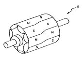
又、図1に示すように得られた対称8極極異方性リング磁石を図6に示すようにシャフト上に固定し、ロータ5を構成し、所定の回転機に組み込んだところ有用な回転機性能が得られた。
【0026】
(比較例1)
前記らせん状磁極部の軸方向長さを殆ど取らずに検討を行った。外見上、複数の極異方性リング磁石をずらし角11°で固着させたように製造し、(らせん状磁極部の軸方向長さ約0.1mm)の極異方性リング磁石の成形体を得た。前記成形体を1100℃にて2時間焼結したところ、このらせん状磁極部からひびが入り焼結割れを起してしまい使用に耐えなかった。
【0027】
(比較例2)
前記らせん状磁極部の軸方向長さを各々の平行磁極部の軸方向長さよりも長くして検討を行った。平行磁極部の軸方向長さを互いに4mmづつ、らせん状磁極部の軸方向長さを7mmとした。それ以外は実施例1と同様にして極異方性リング磁石を製造した。この極異方性リング磁石(N=50)のコギングトルクのバラツキを測定したところ、約10%と大きい値であった。この極異方性リング磁石を実施例1と同様にしてシャフト上に固定し、ロータ5を構成し、所定の回転機に組み込むことは可能であるが、コギングトルクにバラツキがあると各回転機性能の差があるため、大量生産においては安定した製品化が目指せず顧客のニーズから外れてしまうことが解った。
【0028】
(実施例2)
SrCO3粉末(不純物としてBa,Caを含む)及びα−Fe2O3粉末,La2O3粉末及びCo3O4粉末を用いて、仮焼後に(Sr0.80La0.20)O・5.95[(Fe0.983Co0.017)2O3]で示される主要成分組成になるように湿式混合後、1250℃で2時間、大気中で仮焼した。仮焼物をローラーミルで乾式粗粉砕し粗粉を得た。次いで、アトライタにより湿式微粉砕し、平均粒径0.8μm(F.S.S.S.)の微粉砕粉を得、これを公知の手段で造粒した。微粉砕初期に、微粉砕に投入した粗粉に対するmass比でLa2O3粉末のみを0.6mass%添加した。又微粉砕初期に焼結助剤としてSrCO3粉末,CaCO3粉末及びSiO2粉末を微粉砕に投入した粗粉に対するmass比でそれぞれ0.1mass%,1.0mass%及び0.3mass%添加した。
このフェライト磁石用原料のかさ密度を測定したところ1.4Mg/m3であった。次に、図2の成形金型を備え、上ラムとダイスの動きを数値制御できるサーボプレスにより、まず上パンチを引き上げた状態でキャビティ内に所定量の前記微粉末を充填した。金型は8極極異方性型でずらし角11°である。充填された原料の中央が金型屈曲部に一致するようにアンダーフィル作動を行った。キャビティに0.4MA/m(5kOe)のパルス電流で極異方性磁場を間欠的に3回印加した状態としながら上パンチを下降させた。このときダイスを上パンチの半分の速度で下降させながら、成形圧力:44MPa(450kg/cm2)で圧縮成形を行い、下パンチを実質的にキャビティ方向へ加圧した状態とした。その後脱磁し、得られた本成形体の密度は3.2Mg/m3であった。次いで1200℃で2時間焼結し、下記の主要成分組成(La過剰組成:La/Co=1.2)を有する焼結体を得た。
(Sr0.76La0.24)O・5.72[(Fe0.983Co0.017)2O3]
次に焼結体の端面及び外周面を加工(内径面は無加工)し、外径20mm、内径14mm、軸方向長さ30mmの対称8極極異方性リング磁石を得た。次に極異方性付与方向に沿って総磁束量が飽和する条件で着磁し、周方向に表面磁束密度を測定した。
測定場所は軸方向端面から5.0mmステップで5箇所測定した。上の2箇所と下の2箇所はずらし角11°に対応するデータを得た。またらせん状磁極部Bの軸方向長さは8.0mmで、極異方性リング磁石全体の軸方向長さの約27%であった。この極異方性リング磁石(N=50)のコギングトルクのバラツキを測定したところ、2%と非常に小さい値であった。
又、図1に示すように得られた対称8極極異方性リング磁石を図6に示すようにシャフト上に固定し、ロータ5を構成し、所定の回転機に組み込んだところ有用な回転機性能が得られた。
【0029】
(比較例3)
前記らせん状磁極部の軸方向長さを短くして検討を行った。らせん状磁極部の軸方向長さが2.0mmの極異方性リング磁石の成形体を得た。前記成形体を1100℃にて2時間焼結したところ、このらせん状磁極部からひびが入り焼結割れを起してしまい使用に耐えなかった。
【0030】
(比較例4)
前記らせん状磁極部の軸方向長さを各々の平行磁極部の軸方向長さよりも長くして検討を行った。平行磁極部の軸方向長さを互いに8mmづつ、らせん状磁極部の軸方向長さを22mmとした。それ以外は実施例1と同様にして極異方性リング磁石を製造した。この極異方性リング磁石(N=50)のコギングトルクのバラツキを測定したところ、9%と大きい値であった。この極異方性リング磁石を実施例1と同様にしてシャフト上に固定し、ロータ5を構成し、所定の回転機に組み込むことは可能であるが、コギングトルクにバラツキがあると各回転機性能の差があるため、大量生産においては安定した製品化が目指せず顧客のニーズから外れてしまうことが解った。
【0031】
(実施例3)
Nd:29.2mass%、Ga:0.8mass%、B:1.0mass%、Co:10.5mass%、残部Feの主要成分組成を有する合金を真空溶解し、ロール冷却を行って鋳造合金を得た。ロール冷却は銅製の単ロール法を用いており、板厚が300〜500μmになるように作製した。冷却速度は約5×10²℃/secに相当する。この合金に均質化熱処理を施した後、室温で水素吸蔵させ、10℃/secの昇温速度で830℃まで加熱した。この温度で2時間保持した後に1時間脱水素処理を行った。脱水素処理の終了後、炉内をアルゴン雰囲気に置換して冷却した。これにより得られた合金を32〜106μmに分級した。この合金粗粉とエポキシ樹脂を混合し原料とした。
次に、図1に示すらせん状の磁極部配向が可能な図2に記載の成形金型を用い、上ラムとダイスの動きを数値制御できるサーボプレスにより、まず上パンチを引き上げた状態でキャビティ内に所定量の前記原料を充填した。金型は8極極異方性型でずらし角3°とした。充填された原料の中央が金型屈曲部に一致するようにアンダーフィル作動を行った。キャビティに磁極あたり5.0kAターンのパルス電流で極異方性磁場を間欠的に3回印加した状態としながら上パンチを下降させた。
得られた成形体を熱処理して樹脂を硬化させて極異方性ボンデッドリング磁石を得た。電着により熱硬化性樹脂(エポキシ樹脂)をコーティングし、図1に示すような外径14mm、内径10mm、軸方向長さ15mmの対称8極極異方性リング磁石を得た。次に極異方性付与方向に沿って総磁束量が飽和する条件で着磁し、周方向に表面磁束密度を測定した。
測定場所は軸方向端面から2.5mmステップで5箇所測定した。図1において上の平行磁極部(A)2箇所では同様なほぼ正弦波の波形形状が、平行磁極部(C)では(A)の波形形状と比較して11°異相した波形形状が得られた。この極異方性リング磁石(N=50)のコギングトルクのバラツキを測定したところ、1.7%と非常に小さい値であった。
【0032】
(参考例1)
実施例3と同様の原料を用いて極異方性ボンデッドリング磁石を製造した。
図8に示す磁極部配向が可能な図7に記載の成形金型を用いて成形を行った。上ラムとダイスの動きを数値制御できるサーボプレスにより、まず上パンチを引き上げた状態でキャビティ内に所定量の前記原料を充填した。金型は16極極異方性型でずらし角3°とした。充填された原料の中央が金型屈曲部に一致するようにアンダーフィル作動を行った。キャビティに磁極あたり4.0kAターンのパルス電流で極異方性磁場を間欠的に3回印加した状態としながら上パンチを下降させた。得られた本成形体を熱処理して樹脂を硬化させて極異方性ボンデッドリング磁石を得た。電着により熱硬化性樹脂(エポキシ樹脂)をコーティングし、図8に示すような外径14mm、内径8mm、軸方向長さ20mmの対称16極極異方性リング磁石を得た。次に極異方性付与方向に沿って総磁束量が飽和する条件で着磁し、周方向に表面磁束密度を測定した。
測定場所は軸方向端面から4.0mmステップで4箇所測定した。図8に平行磁極部(A)と平行磁極部(C)では3°異相した波形形状が得られ、波形は実質的に同じものであった。この極異方性ボンデッドリング磁石(N=50)のコギングトルクのバラツキを測定したところ、2.2%と非常に小さい値であった。
【0033】
【発明の効果】
以上記述の通り本発明によれば、磁極の間隔のバラツキが少なく、もってコギングトルクのバラツキが小さく、多段成形せずに得られる極異方性リング磁石および成形金型を提供することができた。
【図面の簡単な説明】
【図1】 本発明の極異方性リング磁石の外観を示す模式図である。
【図2】 本発明の極異方性リング磁石の成形に用いる金型構造の一例を示す図である。
【図3】 図2の金型構造の軸断面を示す図である。
【図4】 図1の極異方性リング磁石の側面の展開図である。
【図5】 図1の極異方性リング磁石の表面磁束波形である。
【図6】 本発明の実施例の極異方性リング磁石を用いたロータである。
【図7】 参考例の極異方性リング磁石の成形に用いる金型構造の一例を示す図である。
【図8】 参考例の極異方性リング磁石の外観を示す模式図である。
【図9】 従来の極異方性リング磁石の成形に用いる金型構造を示す図である。
【符号の説明】
1 金型、2b,2c,2d コイル、3 上パンチ、4 下パンチ、
5 ロータ、5a 成形材料、6a 中立線、6b 中立線、
7 ダイス、8 コア、9 スペーサ、10キャビティ、12 溝[0001]
BACKGROUND OF THE INVENTION
The present invention requires multistage molding.AbsentPolar anisotropic ring magnetAnd moldAbout.
[0002]
[Prior art]
Radial anisotropic ring magnets and polar anisotropic ring magnets are often used in rotating machines such as servo motors. Radial of the same dimensions when using a polar anisotropic ring magnetanisotropyA high surface magnetic flux density can be obtained compared to a ring magnet, and a small and higher performance motor can be provided. For example, Japanese Patent Publication No. 8-28293 discloses polar anisotropy.ringThere is a description of magnets.
In a motor using a permanent magnet, cogging is likely to occur because the magnetic resistance between the stator and the rotor changes depending on the rotation angle. In particularPolar anisotropic ringWhen the number of magnetic poles of the magnet is as small as 4 to 8, the cogging torque is significant. Since this cogging torque is proportional to the square of the magnetic flux density, in order to reduce the cogging torque, it is necessary to smooth the circumferential magnetic flux waveform of the gap portion. When a radial anisotropic ring magnet is used, a technique for suppressing cogging by using skew magnetization at the time of magnetization is common.
However, a polar anisotropic ring magnet with a high surface magnetic flux density is radial.anisotropyUnlike a ring magnet, the magnetizable direction is determined from the orientation of molding. Since the orientation is performed while compression molding, variations between the magnetic poles of the molded body are likely to occur, and adjustment by magnetization cannot be performed. Therefore, measures to suppress cogging are necessary.
For example, in Japanese Patent Publication No. 8-28293Number of magnetic polesA polar anisotropic ring magnet having P of 4 to 8 is described, and each magnetic pole portion is uniformly inclined by 5 ° or more with respect to the axis.Polar anisotropic ringmagnetButDescriptionHas been. However, thisPolar anisotropic ringWhen the magnet is actually manufactured, since the magnetic pole part is inclined with respect to the axis, when the magnetic powder is oriented in the mold while compressing and molding, the shape of the magnetic pole part when oriented in the initial stage is compressed.DeformedThere is a problem that the orientation is partially disturbed by the magnetic attraction force with the magnetic pole and the orientation is disturbed. In addition, there is a drawback in that the spacing between the magnetic poles and the skew angle vary due to variations in shrinkage during sintering, and as a result, it is difficult to keep the cogging torque of the motor constant.
Multiple polar anisotropy as a countermeasureringThere is an example of using a magnet and laminating magnetic poles in the axial direction. JP-A-8-340652GazetteThere is a description of a servo motor that is divided into a plurality of polar anisotropic ring magnets in the axial direction and magnetized after shifting the magnetic poles, and apparently skewed, but for reducing the cogging torque There is no description about the control of the shift angle, and eachPolar anisotropic ringIt takes time to fix the magnet. Polar anisotropic ring magnetofThe manufacturing cost is low, but assembly cost to the rotor is required separately.
Japanese Patent Laid-Open No. 11-8960ThenIn order to control the shift angle, the shift angle is controlled by using a magnetic pole shift jig in which the magnetic center of the magnetic field generation unit is shifted by an angle at which the cogging torque has an opposite phase between a plurality of jigs. With this method, when pulling out from the jigPolar anisotropic ringIt is necessary to take fixing means such as adhesion so that the magnet does not rotate, and productivity is poor.
[0003]
[Problems to be solved by the invention]
Therefore, the problem of the present invention is,Magnetic poleofLess variation in spacingWithOf cogging torqueSmall variationWithout multistage moldingInObtained polar anisotropic ring magnetAnd moldIs to provide.
[0004]
[Means for Solving the Problems]
The polar anisotropic ring magnet of the present invention is a one-stage molded polar anisotropic ring magnet, the ring magnet having a plurality of magnetic poles along the axial direction, and each magnetic pole of the ring magnet. In addition, magnetic pole portions parallel to the axial direction are respectively provided at both ends in the axial direction, and further, a helical magnetic pole portion inclined with respect to the axial direction is provided between the parallel magnetic pole portions, and the helical magnetic pole portion The length in the axial direction is shorter than the length in the axial direction of the parallel magnetic pole portions.
In the polar anisotropic ring magnet of the present invention, the inclination of the boundary line (neutral line) of adjacent magnetic poles in the parallel magnetic pole part with respect to the boundary line (neutral line) of adjacent magnetic poles in the helical magnetic pole part The angle α is 85 ° or less.
Whether there are joints by multi-stage moldingThe polar anisotropic ring magnet of the present inventionAxiallyAlongIt can be determined by measuring the surface magnetic flux density. That is1 stepIf molding, since the supply density of magnetic powder is almost uniform when molding,Polar anisotropyThe density does not change at the body of the ring magnet. ThereforeOf the polar anisotropic ring magnetAlthough the surface magnetic flux density at the end portion falls, the surface magnetic flux density does not vary by 5% or more at the body portion. In multi-stage molding, the magnetic powder in the cavity is compressed in multiple times by the punch, so the density difference slightly changes between the part pressed by the punch and the part to which new magnetic powder is supplied, and the surface magnetic flux density at the barrel part It varies from 5% or more, more than 8%. Therefore, by measuring this surface magnetic flux density,1 stepDifferences in molding can be determined.
[0005]
The molding die of the present invention is a die for molding a one-stage molded body of a polar anisotropic ring magnet,
A die having a hollow portion penetrating in the axial direction, a plurality of grooves formed on an inner peripheral surface of the die facing the hollow portion, a magnetic field generating coil embedded in the groove, and an inner periphery of the die A spacer disposed to cover the surface and the groove, a core disposed in the hollow portion of the die and extending along the axial direction of the die, and formed between the spacer and the core. A cavity,
A polar anisotropic orientation magnetic flux corresponding to one magnetic pole of the polar anisotropic orientation magnetic flux generated in the cavity at the time of molding is generated for each coil of the magnetic field generating coil, and The winding portion along the axial direction of the die includes a winding portion parallel to the axial direction of the die and a winding portion inclined between the axial direction of the die formed between the parallel winding portions. It is characterized by the following.
The molding die of the present invention is characterized in that an axial length of the inclined winding portion is shorter than an axial length of the parallel winding portions.
[0006]
DETAILED DESCRIPTION OF THE INVENTION
The advantages of the present invention will now be described in detail with reference to FIGS. 2 and 7,Sign1 is mold, 2b, 2c, 2dIs a coil for obtaining an orientation magnetic field, 3 is an upper punch, 4 is a lower punchTheCavity surrounded by
[0007]
In the polar anisotropy ring magnet of the present invention, as shown in FIG.directionSo as to have a parallel magnetic pole part (hereinafter referred to as a parallel magnetic pole part) A and C.2bIs provided in the mold. As a result, as shown in FIG. 2, even if the molding material is compressed by compression molding, the width and direction of the neutral lines in the magnetic pole portions A and C are not substantially changed, and only the density is improved. The number of spirally oriented magnetic pole portions is small compared to the prior art, and a polar anisotropic ring magnet with reduced magnetic pole variation can be manufactured.
[0008]
If the parallel magnetic pole portions are joined together without leaving a distance, cracks due to shrinkage during sintering are likely to occur. In order to suppress this, it is preferable to provide a certain width of the magnetic pole portion that is spirally oriented. Of course, if the parallel magnetic pole portion and the helical magnetic pole portion are arranged so that the magnetic pole portions are continuous, cracks due to the shrinkage rate during sintering can be further reduced. In this case, the orientation coil may be wound in a mold so as to overlap the
[0009]
By the above manufacturing method, the magnetic pole position and the reverse position (neutral line) as shown in FIG.Axial at both endsParallel toandA polar anisotropic ring magnet running obliquely in the circumferential direction is obtained. During molding, the cavity is arranged so that the magnetic powder in the helical orientation position does not move relative to the mold.InsideBy pressing the magnetic powder of the same distance from both ends for the same distance, the orientation disorder is very small, and it has a certain deviation angle.One-stage moldingPolar anisotropyringmagnetMolded bodyCan be obtained.
[0010]
Axial direction of intermediate part B in FIG.lengthHowever, if it is too short, cracks due to shrinkage during sintering cannot be suppressed. It is necessary to select appropriately according to the molding material, the degree of orientation and the like. For example, R-T-B systemA polar anisotropic ring (R is at least one rare earth element including Y)In the magnetInclination of the boundary line (neutral line) of the adjacent magnetic pole in the spiral magnetic pole part with respect to the boundary line (neutral line) of the adjacent magnetic pole in the parallel magnetic pole partThe angle α is preferably 85 ° or less. A preferable inclination angle is 80 ° or less, and more preferably 70 ° or less. Axial directionlengthIs preferably 0.3 mm or more.
In addition, in a ferrite magnet that is relatively easily sintered and cracked, the inclination angle α is preferably 60 ° or less. A preferable inclination angle is 55 ° or less, and more preferably 45 ° or less. Axial directionlengthIs preferably 0.5 mm or more.
Compared with multi-stage molding, the number of moldings per unit time for one molding machine is greatly improved, and variations in the magnetic pole part can be suppressed as compared with multi-stage moldings.
[0011]
However,BondedIf it is a magnet,CureEven if the process is performed, cracks due to the shrinkage rate hardly occur. Therefore, the neutral line as shown in FIG.6bIt is possible to obtain a polar anisotropic ring magnet having It is also possible to suppress shrinkage cracking by applying an orientation magnetic field to a low level. Thereby, a polar anisotropic ring magnet having a small cogging torque can be obtained.
[0012]
The present inventionPolar anisotropy ring magnetIs produced, for example, by the following steps.
(1)Sintered magnet: Raw material powder production-powder supply-Molding in polar anisotropic magnetic field-Sintering (heat treatment, processing and surface treatment are added if necessary)
(2)Bonded magnet
(Compression molding): Raw material compound production-powder supply-Molding in polar anisotropic magnetic field-Curing (processing and surface treatment are added if necessary)
(Injection molding): Raw material compound production-In polar anisotropy fieldInjectionMolding-Cooling (processing and surface treatment are added if necessary)
[0013]
1 shows geometrically the polar anisotropic ring magnet of the present invention. Figure 1ShowlikePolar anisotropyAlign the center axis of the ring magnet with the z-axis of the r-θ-z cylindrical coordinate system;Polar anisotropic ringOne end of the magnet is brought into contact with the z = 0 plane,Polar anisotropyWhen the ring magnet is virtually divided into three perpendicular to the z axis and named A, B, C from the smaller z, the θ component of the magnetic pole part of A is substantially constant θa in the z axis direction, and the opposite end C The θ component of the corresponding magnetic pole portion is substantially constant θc in the z-axis direction, and the magnetization difficult direction of the intermediate portion (helical magnetic pole portion) B continuously changes from θa to θc. It is. Further, the absolute value | θc−θa | (shift angle) of the θ component of the magnetic pole portions of A and B is 5% or more and 50% or less of the average inter-pole angle of A and B.
[0014]
In order to reduce cogging, the axial direction of the spiral magnetic polelengthButTotal axial length of polar anisotropic ring magnet1-30% or less ofThat's right.
[0015]
FIG. 2 is a schematic sectional view of a mold used in the present invention (however,Molded bodyShows the orientation of the side surface). After the magnetic powder is supplied into the
[0016]
Polar anisotropyForming in a magnetic field to impartIn FIG. 3, the magnetic flux between the magnetic poles is as shown in FIG.In cavity 10Flow in an arc,Particles with magnetic anisotropyTheArrange along arcMake. Polar anisotropyringmagnetMoldingThen, the direction that is easily magnetized is determined by the orientation.Yes. After sinteringMagnetizationdo itWhen the surface magnetic flux density is measured in the circumferential direction, periodic peaks of the magnetic flux density are observed. Neutral line6aCan be defined as a line connecting the positions where the magnetic poles switch. This line uses a magnet viewerto seeI can do things. In addition, by measuring the attractive force with magnetized micro magnets, using X-rays and the Kerr effect,After sinteringNeutral lines can be measured even before magnetization.
8 polesveryanisotropyR-T-B systemSinteringringFIG. 4 shows the result of measuring the neutral line of the magnet and expanding it to the θ-z coordinate. The end faces of two line segments parallel to the z axis are not parallel to the z axisline segmentIt is connected with. Such a neutral lineMagnetismThere are a number equal to the number of poles. Three regions with different θ by drawing two straight lines that pass through the bending point and are parallel to the θ axis(A, B, C)Can be divided into
In the region A, θm = θa + 2πm ÷ n (n isMagnetismNumber of poles, m is1To n)
In the region C, θm = θc + 2πm ÷ n (n isMagnetismNumber of poles, m is1To n)
Can be expressed as The region of the helical magnetic pole portion B is an intermediate transition state between the parallel magnetic pole portions A and C.
θa and θc are inevitable in productionVariationCan be included. TypicalVariationThe value of is within 3% of the angle between the poles, and further within 2%. In the region B, the neutral line continuously changes so as to connect θa and θc. For mold production, it is desirable that the magnetic poles bend with a smooth change according to the thickness of the winding.
The length of the spiral magnetic pole portion B in the axial direction is preferably 1% or more and 40% or less of the entire length. If the helical magnetic pole B is less than 1%, the magnetization direction changes too rapidly,Of polar anisotropic ring magnets in the sintering processEasy magnetization direction and difficult magnetization directionofDifference in shrinkage rate, sinteringas well asHeat treatmentrearDue to the difference in thermal expansion coefficient between the easy magnetization direction and the hard magnetization direction during the cooling, thermal stress is generated and cracks are likely to occur. If the helical magnetic pole portion B exceeds 40%, the rate of disturbing orientation increases due to the effect of the inclined magnetic pole, so the cogging torque is increased.VariationCheap.
Of the helical magnetic pole BAxial directionThe length H can be simply defined as follows. magnetViewerusing, Against the boundary line (neutral line) of adjacent magnetic polesHelical magnetic pole BBorderline of adjacent poles at (Neutral line)ofLeanOblique angleFind α.Polar anisotropic ringThe diameter of the magnet is D,MagnetismIf the number of poles is n, the pole width w is
w = πD ÷ n
And H is represented by the following equation.
H = w / tan α = πD / n / tan α
By the above method, the spiral magnetic pole part BAxial directionYou can know the length.
The absolute value of the angle difference (θc-θa) between the neutral lines at both endsTheThe reason why the average inter-pole angle is set to 5% or more and 50% or less is that if the angle is less than 5%, there is almost no cogging reduction effect. Above 50%motorThe torque becomes 80% or less, and cannot be put to practical use. The cogging torque waveform when the motor is rotated slowly is the rotorMagnetismNumber of poles n and statorMagnetismOften, it has the same number of valleys as the least common multiple M of poles p. Therefore, the desired neutral line angle difference | θc−θa | ≦ 2π / M.
[0017]
When the product is magnetized, it can be divided into two parts: pre-magnetization that generates a weak magnetic field and main magnetization that generates a strong magnetic field.Polar anisotropic ringThe magnet can be rotated and fully magnetized by this magnetization. Set on the magnetized yoke based on the alignment mark,Polar anisotropic ringIf a magnetized yoke that incorporates a magnet and is spontaneously arranged in the easy magnetization direction is used, there is no problem even if preliminary magnetization is omitted.
[0018]
Next, the present inventionPolar anisotropyThe reason for limiting the configuration and numerical values of the ring magnet will be described. Hereinafter, “%” simply means “mass%”.
The polar anisotropic ring magnet of the present invention is, for example, R2T14Sintered magnet having a main phase of B intermetallic compound (R is at least one of rare earth elements including Y and T is Fe or Fe and Co)It is.A composition consisting of R: 27 to 34%, B: 0.5 to 2%, and the balance T (T is Fe or Fe and Co) is selected with the total of R, T and B as main components being 100%. The
Polar anisotropyWhen the mass of the ring magnet is 100%, the inevitable impurities are 0.6% or less, preferably 0.3% or less, more preferably less than 0.2% oxygen, 0.3% or less, preferably 0.00. 1% or less of carbon, 0.08% or less of nitrogen, 0.02% or less of hydrogen, 0.2% or less, preferably 0.05% or less, more preferably 0.02% or less of Ca is allowed. Is done.
A combination of (Nd, Dy), (Pr, Dy) or (Nd, Pr, Dy) as R is highly practical. The R amount is preferably 27 to 34%. A part of Dy may be replaced with Tb. When the R amount is less than 27%, the intrinsic coercive force iHc is significantly reduced, and when it exceeds 34%, the residual magnetic flux density Br and the maximum energy product (BH) max are greatly reduced.
The B content is preferably 0.5 to 2%, more preferably 0.8 to 1.2%. If the amount of B is less than 0.5%, iHc that can withstand practical use cannot be obtained, and if it exceeds 2%, Br and (BH) max greatly decrease. It is known that a part of B can be replaced by C, and is applicable to the present invention.
In order to improve surface magnetic flux density and corrosion resistance, it is preferable to contain an appropriate amount of at least one element selected from the group of Nb, Al, Co, Ga and Cu.
The Nb content is preferably 0.1 to 2%. By containing Nb, a boride of Nb is generated during the sintering process, and abnormal grain growth of crystal grains can be suppressed. If the Nb content is less than 0.1%, the effect of addition is not observed, and if it exceeds 2%, the amount of Nb borides produced increases and the reduction of Br becomes remarkable.
The Al content is preferably 0.02 to 2%. If the Al content is less than 0.02%, the effect of improving iHc and corrosion resistance cannot be obtained, and if it exceeds 2%, Br and (BH) max are significantly reduced.
The Co content is preferably 0.3 to 5%. If the Co content is less than 0.3%, the effect of improving the Curie point and corrosion resistance cannot be obtained, and if it exceeds 5%, both Br and iHc are greatly reduced.
The Ga content is preferably 0.01 to 0.5%. If the Ga content is less than 0.01%, the effect of improving iHc cannot be obtained, and if it exceeds 0.5%, the decrease in Br and (BH) max becomes remarkable.
The Cu content is preferably 0.01 to 1%. If the Cu content is less than 0.01%, the effect of improving the corrosion resistance and iHc cannot be obtained, and if it exceeds 1%, the reduction of Br becomes remarkable.
When both Cu and Co are contained in the specific amount range, an effect of widening the allowable temperature range of the secondary heat treatment is preferably obtained.
The present inventionPolar anisotropy ring magnetIs R2T14In the case of a bonded magnet in which anisotropic magnetic powder having a main phase of B intermetallic compound (R is at least one kind of rare earth element including Y and T is Fe or Fe and Co) is bound by a binder, It is desirable to use magnetic powder having an average crystal grain size of 0.01 to 0.5 μm and imparted anisotropy by a method such as hot working or HDDR. As the binder, rubber, nylon, epoxy, PPS or other plastic materials, zinc, or a low melting point alloy, which are known materials, can be used.
The present inventionPolar anisotropy ring magnetIs bonded with an anisotropic magnetic powder having a main phase of an R—T—N intermetallic compound (R is at least one rare earth element including Y, and T is Fe or Fe and Co). When it is a magnet, it is an intermetallic compound known as Sm-Fe-N, with an average of 1 to 10 μmInIt is desirable to use pulverized anisotropic fine powder. Additives and inevitable impurities that do not significantly degrade the magnetic properties are acceptable. As the binder, rubber, nylon, epoxy, PPS or other plastic materials, zinc, or a low melting point alloy, which are known materials, can be used.
[0019]
If the polar anisotropic ring magnet of the present invention is made of a known ferrite magnet, it is preferable in terms of cost performance.
In particular (A1-xR ’x) O · n [(Fe1-yMy)2O3] (Atomic ratio)
(However, A is Sr and / or Ba, R ′ is at least one of rare earth elements including Y and necessarily contains La, M is Co or Co and Zn, and x, y and n are respectively conditions:
5.0 ≦ n ≦ 6.4
0.01 ≦ x ≦ 0.4, and
0.005 ≦ y ≦ 0.04
It is a number that satisfies When a polar anisotropic sintered ring magnet made of a high-performance ferrite magnet having a main component composition represented by) and having a magnetoplumbite type crystal structure is used, it is preferable because the rotating machine performance can be improved.
In order to increase the saturation magnetization, the ratio of La to R ′ is preferably 50 atomic% or more, more preferably 70 atomic% or more, and particularly preferably 99 atomic% or more. Ideally, R ′ should be composed of La except for the unavoidable R ′ component. Therefore, it is practical to use an inexpensive Misch metal oxide containing 50 atomic% or more of La and the balance of at least one of Pr, Nd, and Ce and an inevitable R ′ component as the R ′ element feedstock. is there. In this case, R 'is composed of La, at least one of Nd, Pr and Ce and an unavoidable R' component.
The molar ratio n needs to be 5.0 to 6.4, more preferably 5.5 to 6.3, and particularly preferably 5.7 to 6.2. When n exceeds 6.4, a different phase other than the magnetoplumbite phase (α-Fe2O3Etc.) iHc is greatly reduced, and when n is less than 5.0, Br is greatly reduced.
x is preferably 0.01 to 0.4, more preferably 0.1 to 0.3, and particularly preferably 0.15 to 0.25. When x is less than 0.01, the effect of addition is not recognized, and when it exceeds 0.4, the surface magnetic flux density is greatly reduced.
Ideally, a relationship of y = x / (2.0n) needs to be established between y and x for charge compensation. However, when y is x / (2.6n) or more, x / If it is (1.6n) or less, a ferrite magnet having a square shape with a high Br and a high demagnetization curve can be obtained. When y deviates from x / (2.0n), Fe2+May be included, but there is no problem. In a typical example, the preferred range for y is 0.04 or less, especially 0.005 to 0.03. Also, an R′-excess major component composition of 5.7 ≦ n ≦ 6.2, 0.2 ≦ x ≦ 0.3 and 1.0 <x / 2ny ≦ 1.3 is selected, and the CaO content is When the content is 0.5 to 1.5% and the content of
SiO as an additive to control sinterability to obtain a dense ferrite sintered magnet2And CaO (CaCO3It is practically important to contain a predetermined amount of).
SiO2Is an additive that suppresses crystal grain growth during sintering, and the total mass of the ferrite magnet is 100%.2The content is preferably 0.05 to 0.55%, more preferably 0.25 to 0.55%. SiO2If the content is less than 0.05%, crystal grain growth proceeds excessively during sintering and the coercive force is greatly reduced. It becomes insufficient and Br greatly decreases.
CaO is an additive that promotes crystal grain growth, and the total mass of the ferrite magnet is 100 mass%, and the CaO content is preferably 0.35 to 1.5%, more preferably 0.4 to 1.5%, 0.5 to 1.5% is particularly preferable. When the CaO content exceeds 1.5%, the crystal grain growth proceeds excessively during sintering, and the coercive force is greatly reduced. When the CaO content is less than 0.35%, the crystal grain growth is excessively suppressed. Improvement is insufficient and Br is greatly reduced.
In the case where the present invention is a bonded magnet in which anisotropic magnetic powder having a known ferrite as a main phase is bonded with a binder, it is preferable in terms of cost performance.
[0020]
Of the present inventionPolar anisotropyThe sintered ring magnet is formed by, for example, a pressing machine equipped with the molding die 1 (for symmetric octupole anisotropic orientation) shown in FIG. In FIG. 3, the solid line is the AA cross section in FIG. 2B, and the broken line is the coil position in the BB cross section. In the molding die 1, 7 is a die made of a ferromagnetic material, and 8 is a core having a circular cross section made of a nonmagnetic material arranged concentrically in the annular space of the
Next, the molding die 1 of FIG.Polar anisotropyAn example of a method for forming a sintered ring magnet shaped body will be described. First, in a state where the
The applied polar anisotropic orientation magnetic field strength is preferably as high as possible, but is usually 0.4 to 2.0 MA / m (5 to 25 kOe). When the orientation magnetic field strength is less than 0.4 MA / m, the orientation becomes insufficient, and it is difficult to ensure a high orientation magnetic field strength of more than 2.0 MA / m for industrial production. In order to suppress cracking and obtain a predetermined degree of orientation, the compression molding pressure is 49 to 392 MPa (500 to 4000 kg / cm in the case of a molded body for an RTB-based sintered magnet.2), And 29 to 39 MPa (300 to 400 kg / cm) in the case of a ferrite magnet shaped body2) Is preferred.
[0021]
If the molding machine is a servo press using a servo motor, a mechanical press using a cam, or a hydraulic press with a numerically controlled hydraulic cylinder, the lower punch is reversed against the movement of the upper punch. By moving the die in the direction or moving the die in the same direction as the movement of the upper punch, a place where the raw material in the mold does not move in the vertical direction (hereinafter referred to as a neutral line) can be set.
The present inventor minimizes the vertical movement of the raw material at the position of the mold for forming the spirally oriented portion by controlling the center of the spirally oriented portion of the mold to coincide with the neutral line.What you can doAnd the effectiveness was confirmed by conducting experiments.
[0022]
Furthermore, sintered magnets andBond magnetIn the manufacture of spiral by combining underfill operationMagnetic poleParallel magnetic poles A and C separated byHelical magnetic poleB'sAxial directionWe also found that the length can be changed. Underfill operation is the upper punch after filling the material into the cavitysoThis is a method of feeding the raw material powder into the mold by moving the relative position of the die and the lower punch before pressurization. By underfillAxial directionIntermediate position B with different lengthPolar anisotropic ringmagnetofYou can bring it to a non-central position. This means that adjustment with emphasis on total torque or cogging torque can be performed using the same mold.
Also, the axial dimensions with the same shift angle differ depending on the use of underfill.Polar anisotropic ringMagnets can be made.
[0023]
In the case of a molded body for an RTB-based sintered magnet, the molded body density: 3.7 to 4.6 Mg / m3In the case of a molded body for sintered ferrite magnets, the molded body density: 2.6 to 3.2 Mg / m3Adjusted to degree. In the case of an R-T-B bonded magnet or an R-T-N bonded magnet, the compression molding is 5.5 to 6.5 Mg / m.3To the extent, 4.0 to 5.7 Mg / m for injection molding3Adjusted to degree. 2.6 to 3.6 Mg / m for ferrite bonded magnet injection molding3Adjusted to degree.
Next, the resulting compression molded body remains in a pressurized stateFor magnetic field generationThe coil is demagnetized by applying a pulse current in the opposite direction to the above. In bonded magnets, demagnetization and powder removal are important because adhesion of magnetic particles affects reliability such as corrosion resistance and contamination.
[0024]
Of the present inventionPolar anisotropyThe dimensions of the sintered ring magnet are not particularly limited, but the axial length (L) and outer diameter dimension (Do) are L = 5 to 100 mm, preferably L = 8 to 50 mm and Do = 3 to 200 mm, respectively. The practicality of Do = 7 to 50 mm is high. It is practically difficult to impart polar anisotropy to those with Do <3 mm.Polar anisotropySintered ring magnets do not meet the needs of miniaturization. And if L <5mmTraditionalThere is no significant difference from a one-stage molded product, and L> 100 mm does not meet the needs for miniaturization.
Of the present inventionPolar anisotropyThe number of magnetic poles of the sintered ring magnet is not particularly limited, but it is highly practical to form 4 to 100 poles, preferably 4 to 24 poles at equal intervals or different intervals in the circumferential direction of the outer diameter surface or inner diameter surface. The variation in cogging torque can be within 2.5%.
[0025]
【Example】
Hereinafter, the present invention will be described in detail by way of examples.ofThe present invention is not limited to the examples.
Example 1
Nd: 30.5 mass%, Dy: 1.5 mass%, Ga: 0.1 mass%, B: 1.0 mass%, Fe: 64.8 mass% The alloy coarse powder having the main component composition in an inert gas atmosphere Finely pulverized by a jet mill to obtain a fine powder for sintered magnet having an average particle size of 4.5 μm (FSSS). When the bulk density of this fine powder for sintered magnet was measured, 1.7 Mg / m3Met. Next, by using the molding die shown in FIG. 2 capable of spiral magnetic pole portion orientation shown in FIG. 1 and the servo press capable of numerically controlling the movement of the upper ram and the die, the upper punch is first pulled up into the cavity. A predetermined amount of the fine powder was filled. 8 moldsveryPolar anisotropy shift angle 11°It is. The underfill operation was performed so that the center of the filled raw material coincided with the bent portion of the mold. The upper punch was lowered while the polar anisotropic magnetic field was intermittently applied three times to the cavity at a pulse current of 5.0 kA turn per magnetic pole. At this time, compression molding was performed while lowering the die at half the speed of the upper punch, and the lower punch was substantially pressurized in the cavity direction. Thereafter, demagnetization was performed, and the density of the obtained molded body was 4.2 Mg / m.3Met.
Next, the molded body was about 0.07 Pa (5 × 10 5-4In Torr) vacuum at 1100 ° C. for 2 hours and cooled to room temperature. Next, a second heat treatment was performed at 550 ° C. for 2 hours in an Ar atmosphere, and the mixture was cooled to room temperature. Next, the end surface and the outer peripheral surface are processed (the inner diameter surface is not processed), and a thermosetting resin (epoxy resin) is coated by electrodeposition, and the outer diameter is 14 mm, the inner diameter is 9 mm, and the axial length is 15 mm. An anisotropic ring magnet was obtained. Next, the magnetic flux was magnetized under the condition that the total magnetic flux amount was saturated along the polar anisotropy application direction, and the surface magnetic flux density was measured in the circumferential direction.
The measurement location was measured at five locations in 2.5 mm steps from the axial end face. Shift angle 11 between the top 2 and bottom 2°The data corresponding to was obtained. The waveform shape is shown in FIG. In the parallel magnetic pole part (A) in FIG. 4, the waveform shape of a substantially sine wave is the same at two locations, and the lower parallel magnetic pole part (C) is 11 in comparison with the waveform shape of (A).°Except for different phases, a substantially equivalent waveform shape was obtained. In addition, the data of the spiral magnetic pole part B was between the two. In addition, the spiral magnetic pole BAxial directionThe length is 3.0mmPolar anisotropic ring magnetoverallAxial directionIt was 20% of the length. When the variation of the cogging torque of this polar anisotropic ring magnet was measured, it was a very small value of 2%. Cogging torque variation is measured by measuring the variation in torque for each cogging when a polar anisotropic ring magnet is assembled with a rotor core and placed in a stator corresponding to the rotor, and then rotated once, and this is measured as 20 samples. The average value is obtained for each sample.
Moreover, as shown in FIG. 6, the symmetrical octupole anisotropic ring magnet obtained as shown in FIG.shaftFixed on top,
[0026]
(Comparative Example 1)
Of the helical magnetic poleAxial directionThe study was conducted with almost no length. Apparently multiple polar anisotropiesringShifting magnet angle 11°Manufactured as fixed with (helical magnetic pole partAxial directionA molded article of a polar anisotropic ring magnet having a length of about 0.1 mm was obtained. The molded body is 1100℃When the material was sintered for 2 hours, cracking occurred from the spiral magnetic pole part, causing sintering cracks, and it could not be used.
[0027]
(Comparative Example 2)
Of the helical magnetic poleAxial directionLength of each parallel magnetic poleAxial length ofIt was considered longer than that. Parallel magnetic poleAxial direction4mm in length each other,Axial direction of helical magnetic poleThe length was 7 mm. Otherwise, a polar anisotropic ring magnet was manufactured in the same manner as in Example 1. When the variation in cogging torque of this polar anisotropic ring magnet (N = 50) was measured, it was a large value of about 10%. This polar anisotropic ring magnet was made the same as in Example 1.shaftFixed on top,Rotor5 can be incorporated into a specified rotating machine, but if there is a variation in cogging torque, there will be a difference in the performance of each rotating machine. I understood that it would come off.
[0028]
(Example 2)
SrCO3Powder (including Ba and Ca as impurities) and α-Fe2O3Powder, La2O3Powder and Co3O4 powder, after calcining (Sr0.80La0.20) O.5.95 [(Fe0.983Co0.017)2O3] After wet mixing so as to have the main component composition shown in FIG. The calcined product was dry-coared with a roller mill to obtain coarse powder. Subsequently, wet fine pulverization was performed with an attritor to obtain fine pulverized powder having an average particle size of 0.8 μm (FSSS), which was granulated by a known means. At the initial stage of fine pulverization, the mass ratio with respect to the coarse powder put into fine pulverization is La.2O3Only 0.6% by mass of powder was added. SrCO3 powder and CaCO as sintering aids at the initial stage of fine grinding3Powder and SiO20.1 mass%, 1.0 mass%, and 0.3 mass% were added by the mass ratio with respect to the coarse powder thrown into the fine grinding | pulverization, respectively.
When the bulk density of this ferrite magnet raw material was measured, it was 1.4 Mg / m.3Met. Next, in the state where the upper punch is first pulled up by a servo press equipped with the molding die of FIG. 2 and capable of numerically controlling the movement of the upper ram and the die.In the cavityWere filled with a predetermined amount of the fine powder. 8 moldsveryPolar anisotropy shift angle 11°It is. The underfill operation was performed so that the center of the filled raw material coincided with the bent portion of the mold. The upper punch was lowered while the polar anisotropic magnetic field was intermittently applied three times to the cavity with a pulse current of 0.4 MA / m (5 kOe). At this time, while lowering the die at half the speed of the upper punch, molding pressure: 44 MPa (450 kg / cm2), And the lower punch was substantially pressed in the cavity direction. Thereafter, demagnetization was performed, and the density of the obtained molded body was 3.2 Mg / m.3Met. Subsequently, sintering was performed at 1200 ° C. for 2 hours to obtain a sintered body having the following main component composition (La excess composition: La / Co = 1.2).
(Sr0.76La0.24) O · 5.72 [(Fe0.983Co0.017)2O3]
Next, the end surface and the outer peripheral surface of the sintered body were processed (the inner diameter surface was not processed) to obtain a symmetrical octupole anisotropic ring magnet having an outer diameter of 20 mm, an inner diameter of 14 mm, and an axial length of 30 mm. Next, the magnetic flux was magnetized under the condition that the total magnetic flux amount was saturated along the polar anisotropy application direction, and the surface magnetic flux density was measured in the circumferential direction.
The measurement location was measured at five points in 5.0 mm steps from the axial end face. The upper two places and the lower two places are 11°The data corresponding to was obtained. In addition, the spiral magnetic pole BAxial directionThe length is 8.0mm,Polar anisotropic ring magnetoverallAxial directionIt was about 27% of the length. When the variation in cogging torque of this polar anisotropic ring magnet (N = 50) was measured, it was a very small value of 2%.
Moreover, as shown in FIG. 6, the symmetrical octupole anisotropic ring magnet obtained as shown in FIG.shaftFixed on top,Rotor 5When it was configured and incorporated in a predetermined rotating machine, useful rotating machine performance was obtained.
[0029]
(Comparative Example 3)
Of the helical magnetic poleAxial directionThe study was conducted by shortening the length. Spiral magnetic poleAxial directionA molded body of a polar anisotropic ring magnet having a length of 2.0 mm was obtained. The molded body is 1100℃When the material was sintered for 2 hours, cracking occurred from the spiral magnetic pole part, causing sintering cracks, and it could not be used.
[0030]
(Comparative Example 4)
Of the helical magnetic poleAxial directionLength of each parallel magnetic poleAxial length ofIt was considered longer than that. Parallel magnetic poleAxial directionThe length is 8mm each other,Axial direction of helical magnetic poleThe length was 22 mm. Otherwise, a polar anisotropic ring magnet was manufactured in the same manner as in Example 1. When the variation of the cogging torque of this polar anisotropic ring magnet (N = 50) was measured, it was a large value of 9%. This polar anisotropic ring magnet was made the same as in Example 1.shaftFixed on top,Rotor5 can be incorporated into a specified rotating machine, but if there is a variation in cogging torque, there will be a difference in the performance of each rotating machine. I understood that it would come off.
[0031]
(Example 3)
An alloy having the main component composition of Nd: 29.2 mass%, Ga: 0.8 mass%, B: 1.0 mass%, Co: 10.5 mass%, and the balance Fe is vacuum-melted and roll-cooled to obtain a cast alloy. Obtained. Roll cooling used the copper single roll method, and it produced so that plate | board thickness might be 300-500 micrometers. Cooling rate is about 5 × 10²Corresponds to ° C / sec. This alloy is subjected to homogenization heat treatment and then stored with hydrogen at room temperature.,It heated to 830 degreeC with the temperature increase rate of 10 degree-C / sec. After maintaining at this temperature for 2 hours, dehydrogenation treatment was performed for 1 hour. After completion of the dehydrogenation treatment, the inside of the furnace was replaced with an argon atmosphere and cooled. The alloy thus obtained was classified to 32-106 μm. This alloy coarse powder and epoxy resin were mixed to obtain a raw material.
Next, using the molding die shown in FIG. 2 capable of helical magnetic pole portion orientation shown in FIG. 1, the cavity is first pulled up by a servo press capable of numerically controlling the movement of the upper ram and the die. Within a predetermined amount of saidmaterialFilled. Mold isOctupoleAn anisotropic type with a shift angle of 3 °. The underfill operation was performed so that the center of the filled raw material coincided with the bent portion of the mold. The upper punch was lowered while the polar anisotropic magnetic field was intermittently applied three times to the cavity at a pulse current of 5.0 kA turn per magnetic pole.
Heat the resulting molded body to cure the resin.Polar anisotropic bondA ring magnet was obtained. A thermosetting resin (epoxy resin) was coated by electrodeposition to obtain a symmetrical octupole anisotropic ring magnet having an outer diameter of 14 mm, an inner diameter of 10 mm, and an axial length of 15 mm as shown in FIG. Next, the magnetic flux was magnetized under the condition that the total magnetic flux amount was saturated along the polar anisotropy application direction, and the surface magnetic flux density was measured in the circumferential direction.
The measurement location was measured at five locations in 2.5 mm steps from the axial end face. In FIG. 1, the waveform shape of a similar sine wave is similar at the two parallel magnetic pole portions (A), and the waveform shape of the parallel magnetic pole portion (C) is 11 compared with the waveform shape of (A).°An out-of-phase waveform shape was obtained. When the variation in cogging torque of this polar anisotropic ring magnet (N = 50) was measured, it was a very small value of 1.7%.
[0032]
(Reference Example 1)
Polar anisotropy using the same raw materials as in Example 3BondedA ring magnet was manufactured.
Figure 8ShowMolding was performed using the molding die shown in FIG. 7 capable of magnetic pole portion orientation. First, a predetermined amount of the raw material was filled in the cavity with the upper punch pulled up by a servo press capable of numerically controlling the movement of the upper ram and the die. 16 moldsveryIt was a polar anisotropic type with a shift angle of 3 °. The underfill operation was performed so that the center of the filled raw material coincided with the bent portion of the mold. The upper punch was lowered while the polar anisotropic magnetic field was intermittently applied three times to the cavity at a pulse current of 4.0 kA turn per magnetic pole. The obtained molded body is heat-treated to cure the resin.Polar anisotropic bondA ring magnet was obtained. A thermosetting resin (epoxy resin) was coated by electrodeposition to obtain a symmetrical 16-pole anisotropic ring magnet having an outer diameter of 14 mm, an inner diameter of 8 mm, and an axial length of 20 mm as shown in FIG. Next, the magnetic flux was magnetized under the condition that the total magnetic flux amount was saturated along the polar anisotropy application direction, and the surface magnetic flux density was measured in the circumferential direction.
The measurement location was measured at four points in 4.0 mm steps from the axial end face. FIG. 8 shows that the parallel magnetic pole part (A) and the parallel magnetic pole part (C) are 3°Out-of-phase waveform shapes were obtained and the waveforms were substantially the same. This polar anisotropyBondedWhen the variation in cogging torque of the ring magnet (N = 50) was measured, it was a very small value of 2.2%.
[0033]
【The invention's effect】
As described above, according to the present invention,Polar anisotropy ring magnet and molding die with little variation in magnetic pole spacing, less variation in cogging torque, and obtained without multi-stage moldingCould be provided.
[Brief description of the drawings]
FIG. 1 is a schematic view showing the appearance of a polar anisotropic ring magnet of the present invention.
FIG. 2 is a view showing an example of a mold structure used for forming a polar anisotropic ring magnet of the present invention.
FIG. 3 is a diagram showing an axial cross section of the mold structure of FIG. 2;
4 is a development view of a side surface of the polar anisotropic ring magnet of FIG. 1; FIG.
FIG. 5 is a surface magnetic flux waveform of the polar anisotropic ring magnet of FIG. 1;
FIG. 6Examples ofThis is a rotor using a polar anisotropic ring magnet.
[Fig. 7]Reference exampleIt is a figure which shows an example of the metal mold | die structure used for shaping | molding of a polar anisotropic ring magnet.
[Fig. 8]Reference exampleIt is a schematic diagram which shows the external appearance of a polar anisotropic ring magnet.
FIG. 9 is a view showing a mold structure used for forming a conventional polar anisotropic ring magnet.
[Explanation of symbols]
1Mold2b, 2c, 2d Coil, 3 upper punch, 4 lower punch,
5Rotor,5a molding material,6a Neutral line,6b Neutral line,
7 dies, 8 cores, 9 spacers, 10 cavities, 12 grooves
Claims (4)
軸方向に貫通した中空部を有するダイスと、前記中空部に面した前記ダイスの内周面に形成された複数の溝と、前記溝に埋設された磁場発生用コイルと、前記ダイスの内周面及び前記溝を覆うように配置されたスペーサと、前記ダイスの中空部に配置されて前記ダイスの軸方向に沿って延設されたコアと、前記スペーサと前記コアとの間に形成されたキャビティとを有し、A die having a hollow portion penetrating in the axial direction, a plurality of grooves formed on an inner peripheral surface of the die facing the hollow portion, a magnetic field generating coil embedded in the groove, and an inner periphery of the die A spacer disposed so as to cover the surface and the groove, a core disposed in a hollow portion of the die and extending along the axial direction of the die, and formed between the spacer and the core. A cavity,
成形時の前記キャビティに発生する極異方性配向磁束のうちの1磁極に対応する極異方性配向磁束は、前記磁場発生用コイルの1つのコイル毎に発生し、前記1つのコイルにおける前記ダイスの軸方向に沿う巻線部分は、前記ダイスの軸方向に平行な巻線部分と、前記の平行な巻線部分の間に形成された前記ダイスの軸方向に対して傾斜した巻線部分とからなることを特徴とする成形金型。A polar anisotropic orientation magnetic flux corresponding to one magnetic pole of the polar anisotropic orientation magnetic flux generated in the cavity at the time of molding is generated for each coil of the magnetic field generating coil, and The winding portion along the axial direction of the die includes a winding portion parallel to the axial direction of the die and a winding portion inclined between the axial direction of the die formed between the parallel winding portions. A molding die characterized by comprising:
Priority Applications (1)
| Application Number | Priority Date | Filing Date | Title |
|---|---|---|---|
| JP2003071550A JP4320710B2 (en) | 2002-03-29 | 2003-03-17 | Polar anisotropic ring magnet and molding die |
Applications Claiming Priority (2)
| Application Number | Priority Date | Filing Date | Title |
|---|---|---|---|
| JP2002094957 | 2002-03-29 | ||
| JP2003071550A JP4320710B2 (en) | 2002-03-29 | 2003-03-17 | Polar anisotropic ring magnet and molding die |
Publications (3)
| Publication Number | Publication Date |
|---|---|
| JP2004007960A JP2004007960A (en) | 2004-01-08 |
| JP2004007960A5 JP2004007960A5 (en) | 2006-03-30 |
| JP4320710B2 true JP4320710B2 (en) | 2009-08-26 |
Family
ID=30446361
Family Applications (1)
| Application Number | Title | Priority Date | Filing Date |
|---|---|---|---|
| JP2003071550A Expired - Lifetime JP4320710B2 (en) | 2002-03-29 | 2003-03-17 | Polar anisotropic ring magnet and molding die |
Country Status (1)
| Country | Link |
|---|---|
| JP (1) | JP4320710B2 (en) |
Families Citing this family (5)
| Publication number | Priority date | Publication date | Assignee | Title |
|---|---|---|---|---|
| JP4279757B2 (en) | 2004-09-22 | 2009-06-17 | 三菱電機株式会社 | Ring-type magnet molded body manufacturing apparatus and ring-type sintered magnet manufacturing method |
| KR101385212B1 (en) * | 2012-12-17 | 2014-04-15 | 엘지이노텍 주식회사 | Motor |
| JP6408820B2 (en) * | 2014-07-29 | 2018-10-17 | 日東電工株式会社 | Permanent magnet for rotating electrical machine, method for manufacturing permanent magnet for rotating electrical machine, rotating electrical machine, and method for manufacturing rotating electrical machine |
| JP2020054199A (en) * | 2018-09-28 | 2020-04-02 | 日本電産サーボ株式会社 | Motor and manufacturing method of motor |
| WO2023021600A1 (en) * | 2021-08-18 | 2023-02-23 | 三菱電機株式会社 | Field element and electric motor |
-
2003
- 2003-03-17 JP JP2003071550A patent/JP4320710B2/en not_active Expired - Lifetime
Also Published As
| Publication number | Publication date |
|---|---|
| JP2004007960A (en) | 2004-01-08 |
Similar Documents
| Publication | Publication Date | Title |
|---|---|---|
| US7906881B2 (en) | Motor | |
| EP2063438B1 (en) | Production method of a radial anisotropic sintered magnet | |
| JP5267459B2 (en) | R-TM-B radial anisotropy ring magnet, manufacturing method thereof, mold for manufacturing the same, and rotor for brushless motor | |
| US4888506A (en) | Voice coil-type linear motor | |
| US20070171017A1 (en) | Radially anisotropic ring magnets and method of manufacture | |
| US7626300B2 (en) | Radial anisotropic cylindrical sintered magnet and permanent magnet motor | |
| US20070151629A1 (en) | Methods of producing radial anisotropic cylinder sintered magnet and permanent magnet motor-use cyclinder multi-pole magnet | |
| JPH01139738A (en) | Method and apparatus for magnetic material having magnetic anisotropy | |
| JP2003017309A (en) | Sintered ring magnet and method of fabricating the ring magnet | |
| JP6384543B2 (en) | Polar anisotropic ring magnet and rotor using the same | |
| JP4320710B2 (en) | Polar anisotropic ring magnet and molding die | |
| JP2002057015A (en) | Anisotropic magnet, its manufacturing method, and motor using the same | |
| JP2004153867A (en) | Radial anisotropic sintered magnet, its manufacturing method, and magnet rotor and motor | |
| JP3719782B2 (en) | Manufacturing method of surface multipolar anisotropic ring magnet | |
| JP2004146542A (en) | Solid material for magnet and its manufacturing method | |
| JP2004146543A (en) | Solid material for magnet and its manufacturing method | |
| JPH04143221A (en) | Production of permanent magnet | |
| JP3809175B2 (en) | Surface multipolar anisotropic ring magnet | |
| JPH08130143A (en) | Anisotropic bonded magnet and manufacturing method | |
| JPH0578166B2 (en) | ||
| JPS62224915A (en) | Manufacture of rare-earth magnet | |
| JP2004146432A (en) | Solid material for magnet | |
| JP2017212421A (en) | Pole-oriented anisotropic compression molding bond magnet and manufacturing method thereof | |
| JPH065642B2 (en) | R-TM-B system radial anisotropic permanent magnet and manufacturing method thereof | |
| JPH07161523A (en) | Rare earth permanent magnet and its production |
Legal Events
| Date | Code | Title | Description |
|---|---|---|---|
| A711 | Notification of change in applicant |
Free format text: JAPANESE INTERMEDIATE CODE: A712 Effective date: 20040526 |
|
| A521 | Request for written amendment filed |
Free format text: JAPANESE INTERMEDIATE CODE: A523 Effective date: 20060203 |
|
| A621 | Written request for application examination |
Free format text: JAPANESE INTERMEDIATE CODE: A621 Effective date: 20060203 |
|
| A711 | Notification of change in applicant |
Free format text: JAPANESE INTERMEDIATE CODE: A712 Effective date: 20070612 |
|
| TRDD | Decision of grant or rejection written | ||
| A01 | Written decision to grant a patent or to grant a registration (utility model) |
Free format text: JAPANESE INTERMEDIATE CODE: A01 Effective date: 20090508 |
|
| A01 | Written decision to grant a patent or to grant a registration (utility model) |
Free format text: JAPANESE INTERMEDIATE CODE: A01 |
|
| A61 | First payment of annual fees (during grant procedure) |
Free format text: JAPANESE INTERMEDIATE CODE: A61 Effective date: 20090521 |
|
| R150 | Certificate of patent or registration of utility model |
Free format text: JAPANESE INTERMEDIATE CODE: R150 Ref document number: 4320710 Country of ref document: JP Free format text: JAPANESE INTERMEDIATE CODE: R150 |
|
| FPAY | Renewal fee payment (event date is renewal date of database) |
Free format text: PAYMENT UNTIL: 20120612 Year of fee payment: 3 |
|
| FPAY | Renewal fee payment (event date is renewal date of database) |
Free format text: PAYMENT UNTIL: 20120612 Year of fee payment: 3 |
|
| FPAY | Renewal fee payment (event date is renewal date of database) |
Free format text: PAYMENT UNTIL: 20130612 Year of fee payment: 4 |
|
| FPAY | Renewal fee payment (event date is renewal date of database) |
Free format text: PAYMENT UNTIL: 20130612 Year of fee payment: 4 |
|
| FPAY | Renewal fee payment (event date is renewal date of database) |
Free format text: PAYMENT UNTIL: 20140612 Year of fee payment: 5 |
|
| EXPY | Cancellation because of completion of term |