JP4320134B2 - Fuel supply unit - Google Patents
Fuel supply unit Download PDFInfo
- Publication number
- JP4320134B2 JP4320134B2 JP2001173839A JP2001173839A JP4320134B2 JP 4320134 B2 JP4320134 B2 JP 4320134B2 JP 2001173839 A JP2001173839 A JP 2001173839A JP 2001173839 A JP2001173839 A JP 2001173839A JP 4320134 B2 JP4320134 B2 JP 4320134B2
- Authority
- JP
- Japan
- Prior art keywords
- reservoir
- fuel
- tank
- supply unit
- fuel supply
- Prior art date
- Legal status (The legal status is an assumption and is not a legal conclusion. Google has not performed a legal analysis and makes no representation as to the accuracy of the status listed.)
- Expired - Fee Related
Links
Images


Classifications
-
- F—MECHANICAL ENGINEERING; LIGHTING; HEATING; WEAPONS; BLASTING
- F02—COMBUSTION ENGINES; HOT-GAS OR COMBUSTION-PRODUCT ENGINE PLANTS
- F02M—SUPPLYING COMBUSTION ENGINES IN GENERAL WITH COMBUSTIBLE MIXTURES OR CONSTITUENTS THEREOF
- F02M37/00—Apparatus or systems for feeding liquid fuel from storage containers to carburettors or fuel-injection apparatus; Arrangements for purifying liquid fuel specially adapted for, or arranged on, internal-combustion engines
- F02M37/04—Feeding by means of driven pumps
- F02M37/08—Feeding by means of driven pumps electrically driven
- F02M37/10—Feeding by means of driven pumps electrically driven submerged in fuel, e.g. in reservoir
- F02M37/103—Mounting pumps on fuel tanks
-
- B—PERFORMING OPERATIONS; TRANSPORTING
- B60—VEHICLES IN GENERAL
- B60K—ARRANGEMENT OR MOUNTING OF PROPULSION UNITS OR OF TRANSMISSIONS IN VEHICLES; ARRANGEMENT OR MOUNTING OF PLURAL DIVERSE PRIME-MOVERS IN VEHICLES; AUXILIARY DRIVES FOR VEHICLES; INSTRUMENTATION OR DASHBOARDS FOR VEHICLES; ARRANGEMENTS IN CONNECTION WITH COOLING, AIR INTAKE, GAS EXHAUST OR FUEL SUPPLY OF PROPULSION UNITS IN VEHICLES
- B60K15/00—Arrangement in connection with fuel supply of combustion engines or other fuel consuming energy converters, e.g. fuel cells; Mounting or construction of fuel tanks
- B60K15/03—Fuel tanks
- B60K15/077—Fuel tanks with means modifying or controlling distribution or motion of fuel, e.g. to prevent noise, surge, splash or fuel starvation
-
- F—MECHANICAL ENGINEERING; LIGHTING; HEATING; WEAPONS; BLASTING
- F02—COMBUSTION ENGINES; HOT-GAS OR COMBUSTION-PRODUCT ENGINE PLANTS
- F02M—SUPPLYING COMBUSTION ENGINES IN GENERAL WITH COMBUSTIBLE MIXTURES OR CONSTITUENTS THEREOF
- F02M37/00—Apparatus or systems for feeding liquid fuel from storage containers to carburettors or fuel-injection apparatus; Arrangements for purifying liquid fuel specially adapted for, or arranged on, internal-combustion engines
- F02M37/22—Arrangements for purifying liquid fuel specially adapted for, or arranged on, internal-combustion engines, e.g. arrangements in the feeding system
- F02M37/32—Arrangements for purifying liquid fuel specially adapted for, or arranged on, internal-combustion engines, e.g. arrangements in the feeding system characterised by filters or filter arrangements
- F02M37/44—Filters structurally associated with pumps
-
- F—MECHANICAL ENGINEERING; LIGHTING; HEATING; WEAPONS; BLASTING
- F02—COMBUSTION ENGINES; HOT-GAS OR COMBUSTION-PRODUCT ENGINE PLANTS
- F02M—SUPPLYING COMBUSTION ENGINES IN GENERAL WITH COMBUSTIBLE MIXTURES OR CONSTITUENTS THEREOF
- F02M37/00—Apparatus or systems for feeding liquid fuel from storage containers to carburettors or fuel-injection apparatus; Arrangements for purifying liquid fuel specially adapted for, or arranged on, internal-combustion engines
- F02M37/22—Arrangements for purifying liquid fuel specially adapted for, or arranged on, internal-combustion engines, e.g. arrangements in the feeding system
- F02M37/32—Arrangements for purifying liquid fuel specially adapted for, or arranged on, internal-combustion engines, e.g. arrangements in the feeding system characterised by filters or filter arrangements
- F02M37/46—Filters structurally associated with pressure regulators
-
- F—MECHANICAL ENGINEERING; LIGHTING; HEATING; WEAPONS; BLASTING
- F02—COMBUSTION ENGINES; HOT-GAS OR COMBUSTION-PRODUCT ENGINE PLANTS
- F02M—SUPPLYING COMBUSTION ENGINES IN GENERAL WITH COMBUSTIBLE MIXTURES OR CONSTITUENTS THEREOF
- F02M37/00—Apparatus or systems for feeding liquid fuel from storage containers to carburettors or fuel-injection apparatus; Arrangements for purifying liquid fuel specially adapted for, or arranged on, internal-combustion engines
- F02M37/22—Arrangements for purifying liquid fuel specially adapted for, or arranged on, internal-combustion engines, e.g. arrangements in the feeding system
- F02M37/32—Arrangements for purifying liquid fuel specially adapted for, or arranged on, internal-combustion engines, e.g. arrangements in the feeding system characterised by filters or filter arrangements
- F02M37/50—Filters arranged in or on fuel tanks
-
- B—PERFORMING OPERATIONS; TRANSPORTING
- B60—VEHICLES IN GENERAL
- B60K—ARRANGEMENT OR MOUNTING OF PROPULSION UNITS OR OF TRANSMISSIONS IN VEHICLES; ARRANGEMENT OR MOUNTING OF PLURAL DIVERSE PRIME-MOVERS IN VEHICLES; AUXILIARY DRIVES FOR VEHICLES; INSTRUMENTATION OR DASHBOARDS FOR VEHICLES; ARRANGEMENTS IN CONNECTION WITH COOLING, AIR INTAKE, GAS EXHAUST OR FUEL SUPPLY OF PROPULSION UNITS IN VEHICLES
- B60K15/00—Arrangement in connection with fuel supply of combustion engines or other fuel consuming energy converters, e.g. fuel cells; Mounting or construction of fuel tanks
- B60K15/03—Fuel tanks
- B60K2015/03105—Fuel tanks with supplementary interior tanks inside the fuel tank
-
- B—PERFORMING OPERATIONS; TRANSPORTING
- B60—VEHICLES IN GENERAL
- B60K—ARRANGEMENT OR MOUNTING OF PROPULSION UNITS OR OF TRANSMISSIONS IN VEHICLES; ARRANGEMENT OR MOUNTING OF PLURAL DIVERSE PRIME-MOVERS IN VEHICLES; AUXILIARY DRIVES FOR VEHICLES; INSTRUMENTATION OR DASHBOARDS FOR VEHICLES; ARRANGEMENTS IN CONNECTION WITH COOLING, AIR INTAKE, GAS EXHAUST OR FUEL SUPPLY OF PROPULSION UNITS IN VEHICLES
- B60K15/00—Arrangement in connection with fuel supply of combustion engines or other fuel consuming energy converters, e.g. fuel cells; Mounting or construction of fuel tanks
- B60K15/03—Fuel tanks
- B60K2015/03236—Fuel tanks characterised by special filters, the mounting thereof
-
- Y—GENERAL TAGGING OF NEW TECHNOLOGICAL DEVELOPMENTS; GENERAL TAGGING OF CROSS-SECTIONAL TECHNOLOGIES SPANNING OVER SEVERAL SECTIONS OF THE IPC; TECHNICAL SUBJECTS COVERED BY FORMER USPC CROSS-REFERENCE ART COLLECTIONS [XRACs] AND DIGESTS
- Y10—TECHNICAL SUBJECTS COVERED BY FORMER USPC
- Y10T—TECHNICAL SUBJECTS COVERED BY FORMER US CLASSIFICATION
- Y10T137/00—Fluid handling
- Y10T137/8593—Systems
- Y10T137/85978—With pump
-
- Y—GENERAL TAGGING OF NEW TECHNOLOGICAL DEVELOPMENTS; GENERAL TAGGING OF CROSS-SECTIONAL TECHNOLOGIES SPANNING OVER SEVERAL SECTIONS OF THE IPC; TECHNICAL SUBJECTS COVERED BY FORMER USPC CROSS-REFERENCE ART COLLECTIONS [XRACs] AND DIGESTS
- Y10—TECHNICAL SUBJECTS COVERED BY FORMER USPC
- Y10T—TECHNICAL SUBJECTS COVERED BY FORMER US CLASSIFICATION
- Y10T137/00—Fluid handling
- Y10T137/8593—Systems
- Y10T137/86187—Plural tanks or compartments connected for serial flow
Description
【0001】
【発明の属する技術分野】
本発明は、例えば自動車のエンジンなどの内燃機関に燃料を供給するための燃料送給ユニットに関するものである。
【0002】
【従来の技術】
この種の目的に使用される典型的な燃料送給ユニットは、燃料タンク内の底部に対して例えば圧縮ばね又は弾性緩衝部材によってユニットを固定支持するための取付ホルダを備えている。ユニットは、少なくとも1つのリザーバと、リザーバ内部に配置された燃料ポンプと、必要に応じて燃料フィルタと、ユニットを燃料タンク内に組み込むためにタンクに設けられた組込穴を閉鎖するためのキャップとを備えている。このような形式の燃料送給ユニットは、例えばヨーロッパ特許公報第0203244号、同第0297256号、更にはドイツ公開特許公報第19615081号により公知である。
【0003】
この種の燃料送給ユニットは、リザーバ即ち貯留ポットと、燃料ポンプと、燃料フィルタと、燃料タンク組込穴閉鎖用キャップとからなる一体的な組立構体として燃料タンクに対する組込みと取外しができ、しかも燃料タンクの内底面に確実に固定できるものでなければならない。またこのような燃料送給ユニットは、一方では修理又は整備に際してユニット全体の迅速確実な交換が保証されなければならず、他方では使用燃料タンクに予測されるタンク内高寸法の公差に適合できるものでなければならない。このため、ユニット中の少なくとも燃料供給ポンプ、即ち、好ましくは貯留ポットとその中に配置される燃料ポンプが組込穴閉鎖用キャップもしくはキャップフランジに関して軸方向に摺動変位可能となるように燃料送給ユニットを構成することでタンク内高寸法の公差を補償できるようにした種々の提案が既になされている。例えば、前掲のヨーロッパ特許公報第0297256号で提案されている燃料送給ユニットは、圧力管路及び戻り管路を備えた電動燃料ポンプが伸縮ガイドを介して軸方向に摺動変位できるように構成され、付加的に燃料ポンプを遮音支承するための措置が施されている。
【0004】
ところで、最近の自動車用燃料タンクは良く知られているように分岐部の多い構造形態であり、その組込穴閉鎖用キャップやキャップフランジのための平坦面が僅かしかなく、燃料送給ユニットの組込スペースも限られているので、必然的に燃料送給ユニットのほうを極力コンパクトに構成することが主な要請となっている。しかしながら、他方で確保されなければならない点として、燃料送給ユニットに属するリザーバには、燃料ポンプのために充分な吐出量余裕、即ち燃料貯留容積を提供することと、自動車が曲線路を走行中又は加速状態にあるときに内燃機関に対する正常な燃料供給を保証することが要求される。更に、リザーバ内の燃料貯留容積は予備容積として利用されることが多く、この場合は、燃料タンクの主貯油容積が完全に空になったときに燃料レベル計測システムが燃料タンク内の一つ以上の主液位センサからリザーバ内に設けられている予備又は副液位センサに切り換えられ、それによりリザーバの限定された容積を起点とする予備燃料の極力正確な残量レベルの表示を得ている。この場合、リザーバの容積は極力大きいほうが望ましいが、一方ではタンク内へ燃料送給ユニットを組み込むためにタンクに設けられている組込穴は組込後に完璧な密封状態を得るために或る特定の寸法を超えてはならず、このことを考慮に入れると、リザーバの容積を大きくすることは、組込穴を極力小さくするために燃料送給ユニットをなるべくコンパクトな小寸法の構成にしなければならないと言う要求と矛盾する。
【0005】
このような課題は、例えばドイツ特許公報第3225929号で既に言及されている。この提案では、係る課題を解決するために、貯留ポット又はサージポットとしてのリザーバを取付完了位置においてタンク底上で互いに係止可能な複数の部品で構成している。この場合、ポットの部品の一つがポットに続いてタンク内に挿入される燃料送給装置アッセンブリーのためのホルダを形成している。一方、この燃料送給装置アッセンブリーは、構造高さが比較的低いタンク内でも使用できるように燃料タンクの底に対して或る傾斜角で取付ける必要がある。しかしながら、このようなリザーバの設計構造は上述のような形式の燃料送給ユニットの場合には適合が困難であり、むしろリザーバと燃料送給装置アッセンブリーの個々の部品を特定の順序で組立てなければならないと言う不都合を生じる。
【0006】
またドイツ公開特許公報第19528182号には燃料タンク内への組込用の液位センサ付き燃料送給ユニットが述べられ、そこでは燃料送給装置アッセンブリーを受け入れるホルダが軸方向への摺動及び回転ができるようにタンクのフランジ上に配置されている。この設計構造では、燃料送給装置アッセンブリーのホルダ下端部は燃料タンク又はポットの内底面上で枢動的に調心可能であり、従って燃料タンクのフランジ及び/又はタンク底面の目標位置からの角度偏差によって燃料送給ユニットに配置される液位センサの測定精度が影響を受けることがない。また、この設計構造では燃料ポンプを収容した比較的大きなリザーバを含んでおり、このリザーバは、ばね要素を介して回転及び揺動可能に配置されてフィルタケース内に収容された燃料フィルタと共に組立ユニットを形成している。燃料送給ユニットの組立はその取付完了状態にほぼ相当する構成で行われる。この場合の個々の部品相互の配置は更にタンクに比較的大きな組込穴を必要とし、これは先に述べたように望ましいものではない。
【0007】
更にヨーロッパ公開特許公報第0922603号に開示されている二つの燃料リザーバを燃料タンク内に組み込む配置構成では、各リザーバは一側部と底部で可撓性バーを介してフレキシブルに相互連結されており、この可撓性バーにより両リザーバが組立中の状態において相対的に角度を持つことができるようになっている。先にタンク内に導入されるほうの第1リザーバは、その上端面がまずタンク底面に対して横切る向きとなるように傾斜状態でタンクの組込穴に挿入される。この第1リザーバを取付完了位置に配置するには、続に第2のリザーバ、即ち主リザーバをタンクの組込穴に導入する際に第1リザーバをタンク内で90°回動させる必要があり、この場合、主リザーバをタンクの組込穴中で傾けなければならない。これは、この配置構成のものをタンク内に導入する操作が極めて面倒で時間を要するものであることを意味している。結局、先にタンク内へ導入したリザーバを回動させる際に後からタンク内へ導入すべきリザーバを傾けなければならないことから、組込穴の内法幅は相応に大きく選定しなければならず、これは先に述べたように基本的に望ましくないことである。
【0008】
【発明が解決しようとする課題】
本発明の課題は、上述の従来技術の諸問題点を解消して、燃料ポンプに対して常に充分な吐出量の余裕を与え、しかもコンパクトで燃料タンクの組込穴を比較的小さくすることができる燃料送給ユニットを提供することである。
【0009】
【課題を解決するための手段】
本発明による燃料送給ユニットは、少なくとも1つの第1リザーバと、第1リザーバの内部に配置された燃料ポンプと、燃料タンクに設けられた組込穴に係合してこれを閉鎖するキャップと、第1リザーバ及びキャップを保持する取付ホルダとを備え、取付ホルダと共に第1リザーバを燃料タンク内へ導入するための組立位置から組込穴を介して燃料タンク内の取付位置へ持ち来たしてキャップを燃料タンクの組込穴に係合したときに取付ホルダが圧縮ばね又は弾性緩衝部材によって燃料タンクの底部に対する固定配置状態を達成する形式の燃料送給ユニットであり、特に前述の課題を解決するために、組立位置で第1リザーバよりも側方に位置し且つこれと連通した第2リザーバを更に備え、第1及び第2リザーバは共に前記組立位置にある状態から前記組込穴を通して燃料タンク内の取付位置に挿入される間に両リザーバの軸方向の向きを取付位置における軸方向向きと一致させたまま前記組込穴の軸心方向に沿って互いに相対移動可能に取付ホルダによって支持され、取付位置においては第1及び第2リザーバが互いに側方に隣接すると共に燃料タンク内で少なくとも一方のリザーバが少なくとも部分的にキャップの軸方向投影面の外側にはみ出して配置されていることを特徴とするものである。
【0010】
本発明において、第1及び第2リザーバが軸方向に整列した状態を維持すると言うことは、組立時もしくはタンクへの導入時に両リザーバの軸方向における基本的な向きが取付位置における軸方向の基本的向きと一致していなければならないことを意味する。燃料送給ユニットに対するこのような構成によって燃料送給ユニットの個々の組立構体を相対移動、即ち、組立位置から取付位置へ或いはその逆へと相対的に旋回又は軸方向変位させることが可能であり、これにより燃料送給ユニットは組立位置では取付位置にあるときよりも少ないスペースを要するだけとなり、燃料タンクの比較的小さな組込穴を通してタンク内へ装着可能となる。また、燃料送給ユニットが取付位置にある状態においてその構成部品を最終取付完了位置へ向けて相対移動させることができるので、タンク底面上における燃料送給ユニットの固定は、組立位置よりも比較的大きなスペースが与えられる取付位置において行うことができる。
【0011】
本発明の好適な態様においては、少なくとも1つのリザーバ、好ましくは第1リザーバが取付ホルダ又は他方のリザーバ上で軸方向移動可能に案内され、組込の目的でその組込穴閉鎖用キャップに対する間隔を変えることができるようになっている。これにより得られる配置全体の「伸張可能な機能」により、先にタンク内に導入した燃料送給ユニット部品をユニット全体の完全な導入の前に取付位置に移動させることができる。
【0012】
本発明の更に別の好適な態様においては、第2リザーバがキャップの軸方向投影面の内側に配置されている。
【0013】
リザーバを組込穴の軸心方向に沿って相対移動可能に案内する手段としては、例えば第1リザーバと第2リザーバとの間に二つの摺動可能なスライド部材を設けることができ、このスライド部材の伸長寸法は、タンクの組込穴に先に挿入されるほうのリザーバを組込穴の内径の拡がりの範囲内で組込穴の軸心方向とほぼ直交する方向へずらして取付位置に持ち来たし得るように選ぶことが好ましい。スライド部材を二つ設ける代わりに単一のスライド部材或いは三つ以上のスライド部材としてもよいことは述べるまでもない。
【0014】
本発明による燃料送給ユニットの更に別の好適な態様によれば、スライド部材は端部ストッパーを備えた案内レールを含んでおり、この案内レールの一端は第1リザーバのスライドガイドによって、また他端は第2リザーバのスライドガイド又は取付ホルダのスライドガイドによって、それぞれ軸方向摺動可能に且つ捩り剛性を持たせて案内されている。これにより配置全体の「伸縮可能な機能」を実現し、また案内レールの端部ストッパーによりスライドガイドが案内レールから外れることを不可能にすると同時に伸張量の上限を規制し、その結果、取付ホルダと第2リザーバによって第1リザーバをタンク底面に確実に押付けるようにしてある。
【0015】
本発明の更に別の好適な態様によれば、案内レールは断面I形の異形レールとして構成されており、各スライドガイドはこのI異形レールのフランジ部を対応する断面形状で抱持する断面C形の異形溝として構成されている。
【0016】
本発明の更に別の好ましい態様によれば、第1及び第2リザーバはそれぞれ底部側で軟質の接続管路を介して互いに連通されており、それによって各リザーバの液位が必ず同じレベルとなるようにしてある。燃料送給ポンプ、即ち燃料送給アッセンブリーはいずれか一方のみのリザーバ内に配置しておいてもよく、その場合も上記接続管路による連通で両方のリザーバが同時に且つ互いに均一な液位で排出を終えることが保証されている。
【0017】
但し、それぞれのリザーバ内に燃料供給アッセンブリーを配置し、両方のリザーバから燃料をエンジンに送るようにしたり、或いは一方のリザーバから他方のリザーバへ燃料を送るようにしたりすることも可能である。
【0018】
本発明の燃料送給ユニットの特に好ましい形態によれば、両リザーバ間の接続管路が実質的に各リザーバの下面に沿って延在しており、特に接続管路が伸長状態、即ちユニットが組立位置にあるときには、接続管路が各リザーバの軸方向投影面から殆ど又は全く張り出さないように配置されている。これにより、タンクの組込穴の直径は、組立操作に支承を生じない程度でリザーバの外径よりも極く僅かに大きい値に選定すれば充分である。
【0019】
本発明の更に別の好適な態様によれば、各リザーバに対する接続管路の接続位置は、タンクの傾斜時で且つリザーバ内の液位が低いときに燃料ポンプを収容しているほうのリザーバからの燃料の流出を遮断する一方でこのリザーバへの他方のリザーバからの燃料の流入を許容する位置に選ばれている。
【0020】
本発明の更に別の好適な態様によれば、キャップと両リザーバのうちの好ましくは第2リザーバとの間に燃料フィルタが配置されており、燃料フィルタの下部に設けられた圧力制御弁からの戻り燃料がキャップの下方に配置されている第2リザーバ内に供給されるようになっている。これによりキャップとリザーバとの間にあるスペースが最適に有効利用され、燃料フィルタ、即ち燃料フィルタのケースと第2リザーバとを互いに一直線に並べて配置でき、例えば燃料フィルタケースに接続された圧力制御弁は取付完了状態で第2リザーバ内に少なくとも部分的に挿入された状態にすることができる。
【0021】
この場合、更に好ましくは燃料フィルタをフィルタケース内に収納し、このフィルタユニットとキャップとで一つの構造ユニットを形成するとよい。
【0022】
本発明の更に好適な態様によれば、取付ホルダはタンクの底面上で構成全体を固定するために圧縮ばねの作用に抗して伸縮可能なリンクを構成している。
【0023】
尚、本発明による燃料送給ユニットは、リザーバを互いに相対回動可能に取付ホルダに配置した構成とすることもでき、その場合、組立位置にあるときはキャップと両リザーバは軸方向に整列して互いに一直線上に並んだ配置をとり、取付位置にあるときはリザーバの一つ、好ましくは最も下位に位置するリザーバが少なくとも取付ホルダに関して回動可能に且つ軸方向移動可能に構成される。その場合、最下位に配置されるリザーバは、回動操作のためのレンチ又は回動伸縮運動を開始させるための受け部としてタンク底部に特設されている突起を介して組立時にホルダに導入されるトルクにより回動される。選択的に各リザーバは組立位置にある状態でばねによる付勢とロック機構で互いに一直線上に並んだ状態に配置しておくことも可能であり、取付完了位置への最終的な位置調整はロック機構を解除してばねの復元力で各部品が取付完了位置に移行するようにすることも可能である。この場合、両リザーバを取付完了位置で互いに相対的に固定するために付加的な手段を設けておく必要がある。次いで、その上に配置されるリザーバとキャップ、場合によっては更にフィルタケースも一緒に上から押し込んで畳み込めば、これらを最終取付状態に持ち来すことができる。
【0024】
図示の実施例に基づいて本発明の燃料送給ユニットを説明すれば以下の通りである。
【0025】
【発明の実施の形態】
図1及び図2に示すように、本実施例による燃料送給ユニット1は例えば自動車用燃料タンクの内部に配置されるものであって、第1リザーバ2と、第1リザーバ2の内部に配置された燃料ポンプ3と、第2リザーバ4と、キャップ5と、キャップ5の下面に配置された燃料フィルタケース6と、フィルターケース6の内部に配置された燃料フィルタ7とを含んでいる。キャップ5と第2リザーバ4は取付ホルダ8を介して弾力的に伸縮可能に相互連結されている。図示の実施例では、取付ホルダ8は互いに離間してキャップ5の下面に設けられた2つの管状受容部9を備え、これら受容部は好ましくは第2リザーバ4に一体に結合された2つの内筒10を受容し、内筒10は受容部9よりも僅かに小さな直径を有している。内筒10と受容部9は、それらの内部に配設された圧縮ばね11によって互いに反発するように付勢されており、受容部9からの内筒10の抜け出しは公知の手法と同様にストッパーで防止されている。
【0026】
第1リザーバ2と対面する側面で第2リザーバ4には2つのスライドガイド12がC異形溝の形態で設けられており、I異形レールの形態のスライド部材13が摺動可能にこのスライドガイド内に位置している。第2リザーバ4に対面する第1リザーバ2の側面もしくはその周面にもやはりC異形溝の形態のスライドガイド12が設けられており、このガイド内にも前記スライド部材13が同様に摺動可能に位置している。スライドガイド12はスライド部材13のI異形レールのフランジ部をそれぞれ対応する形状で抱持し、各スライド部材13の両端部と各スライドガイド12の両端部にはそれぞれ互いに衝合する端部ストッパー14が設けられている。これらの端部ストッパーは、一方でスライド部材13の伸張長さを規制し、他方で図4と図5に示した燃料送給ユニット1の取付位置において第1リザーバ2が取付ホルダ8の圧縮ばね11を介してタンク16の底面15に確実に押付けられることを保証している。
【0027】
ここに示した実施例による燃料送給ユニット1の構成では、リザーバ2と4がスライド部材13を介して互いに直接結合されているが、本発明はこれに限定されるものではなく、例えば第2リザーバ4の下方から取付ホルダ8が係合していても良く、その場合はスライド部材13は取付ホルダ8のスライドガイド12内で案内されることになる。
【0028】
リザーバ2と4はそれぞれ底部で接続管路17を介して互いに連通され、そのために設けられている接続ニップル18は、タンク16が傾いたときには燃料が第2リザーバ4から第1リザーバ2へと流れることができるが、リザーバ2及び4内の燃料液位が低いときに車両が横に傾いたり或いは加速されたりしたときには第1リザーバ2から第2リザーバ4への燃料流出が遮断されるような相対位置で配置されている。このような特定の相対位置の一例は特に図7の底面図に示されており、そこでは第1リザーバ2の接続ニップル18は第2リザーバ4から遠い方の側縁部で第1リザーバの底部に配置され、第2リザーバ4の接続ニップル18は第1リザーバ2に対面する近接側の側縁部で第2リザーバの底部に配置されている。燃料送給ユニットの平面図(図6)と底面図(図7)に示すように、本実施例におけるリザーバ2と4、キャップ5及び燃料フィルタケース6は円形の断面形状に構成されているが、本発明はこれに限定されるものではなく、燃料タンクの組込穴32から挿入できる断面形状であればよい。
【0029】
更に、特に図7の底面図に明らかなように、接続管路17はリザーバ2及び4の軸方向投影面の殆ど内側に延在しており、リザーバ2及び4は底部にそれぞれ脚部19を備え、この脚部は取付位置においてタンクの底面15上に直立してリザーバ底面20とタンク16の底面15との間に間隙を形成する。第1リザーバ2の底面20とタンク16の底面15との間隔は、第2リザーバ4の底面20とタンク16の底面15との間隔よりもかなり小さい。第2リザーバ4の底面20とタンク16の底面15との間に形成される間隙には燃料送給ユニットが取付位置にあるときに接続管路17が収まり、しかもその状態で接続管路17は第2リザーバ4の底面20の下方になお動ける余地を有している。第1リザーバ2の底面20には段差部37が設けられており、この段差部はリザーバの周縁の一部の範囲に亘って接続管路17の一部を受け入れるための凹部を形成している。接続ニップル18は第1リザーバ2の底面20よりも高い位置に配置されており、これにより、例えばリザーバ2と4内の燃料液位が低いときにタンク16が或る程度傾いたり、或いはこの傾斜に相当する液面傾斜を生じるような加速度変化がタンク16に加わったりしても、燃料が第1リザーバ2から第2リザーバ4へ逆流しないような保証措置がとられている。また、第2リザーバ4から第1リザーバ2への燃料の流れ込みを容易にする目的で第2リザーバ4の底面20は第1リザーバの方向に傾けた配置としてある。
【0030】
燃料送給ユニット1の作動時の機能について述べると、第1リザーバ2内に配置された燃料ポンプ3は送出管路21を介して燃料フィルタケース6内に燃料を送り込み、該ケース内に配置されている燃料フィルタ7を通過した燃料は圧力短管22を介して自動車エンジンに至る図示しない燃料供給部へと送り出される。燃料フィルタ7自体は公知のフィルタエレメントとして構成されており、その構造の詳細については説明を省略する。いずれにしても燃料ポンプ3は自動車エンジンが必要とするよりも多量の体積流量で燃料を圧送し、その一部の部分体積流が分岐部23を介して吸引ジェットポンプ24に供給され、他の部分体積流が圧力制御弁25を介して第2リザーバ4に送り込まれるようになっている。圧力制御弁25は燃料フィルタケース6の下面に直接接続されており、燃料送給ユニットが取付完了状態になると少なくとも部分的に第2リザーバ4内に入り込み、圧力制御弁25が第2リザーバ内で直接開口することになる。
【0031】
送出管路21の分岐部23には別の管路26が接続されており、この管路26が吸引ジェットポンプ24に通じている。燃料の主な流れから分岐されて吸引ジェットポンプ24へ送られる部分流により吸引ジェットポンプ24内で推進噴流が生成され、この推進噴流が同様にタンク16内にある燃料中に周知の挙動で吸引噴流を誘起する。
【0032】
特に図1と図2に示されているように、吸引ジェットポンプ24の噴出ノズル27は第1リザーバの底面20の直下に配置されており、噴出ノズル27に対面して同様の位置に設けられている捕捉ノズル28と整列している。捕捉ノズルは立上り管29に連通し、この立上り管は第1リザーバの底面20の下から上縁30のすぐ下にまで達してそこで成端しているので、作動中、そして特にポンプ停止時のも、両リザーバ2、4が完全に燃料で満たされることは持続的に確保されている。
【0033】
スペース上の理由から、管路26は第1リザーバ内をほぼ垂直に貫通する通路31に接続されており、この通路の下端に噴出ノズル27が接続されている。勿論、噴出ノズル27はタンク16の最深部に配置されていることは述べるまでもない。
【0034】
燃料送給ユニット1の取付け作業について述べると以下の通りである。
図1には、燃料送給ユニット1が組立位置の開始位置、即ち組込作業の初期に伸長している状態にある様子が示されている。第1リザーバ2は第2リザーバ4に関して軸方向にずらしてあり、しかもレールとして構成されたスライド部材13は最大伸張寸法をとっている。このため、送出管路21と接続管路17は伸長状態、即ちほぼ伸長しきった状態で延在している。第1リザーバ2はタンク16の組込穴32を通して既にタンク内に導入されている。図1から判るように、スライド部材13の長さは、図示位置において燃料送給ユニット全体が組込穴32の内側で穴の内径の拡がりを利用して矢印33の方向に移動できるように、しかもその際に第2リザーバ4の底面20とその下に突き出ている接続ニップル18及び脚部19が組込穴32の鍔部35と干渉することがないような最適寸法に設計されている。従って、燃料送給ユニット1は矢印33の方向への横シフト操作と共に矢印34の方向へ下降させれば図3に示す組立位置に移動可能である。この図3の組立位置において、第1リザーバ2はその脚部19でタンク16の底面15上に直立する。この状態ではユニット全体を軸方向に畳み込むことができ、第2リザーバ4とその上に配置された燃料フィルタケース6及びキャップ5が組込穴32内に導入可能となっている。この場合、燃料フィルタケース6と第2リザーバ4がキャップ5の軸方向投影面の内側に収まるように配置されていなければならないことは当然である。この状態からキャップ5を軸方向下方へ押し込んで燃料送給ユニットを軸方向に畳み込むと、スライド部材13が両リザーバ2及び4に設けられているスライドガイド12内に完全に入り込み、燃料送給ユニットは図4に示す組立位置を占め、第2リザーバ4の脚部19がタンク16の底面15に直立して着底する。この位置においてはスライド部材13及び各スライドガイド12の各両端に設けられている端部ストッパーが有効となり、上側端部ストッパー14は第2リザーバ4のスライドガイド12と、またスライド部材13の各下側端部ストッパー14は第1リザーバ2のスライドガイド12とそれぞれ衝合する。更にキャップ5を軸方向に押し込んでユニット1がタンク16の底面15に対して固定配置される取付位置へと畳み込むと、取付ホルダ8の圧縮ばね11のばね力が第2リザーバ4を介して第1リザーバ2に作用し、キャップ5を組込穴32の鍔部35にクランプすると第1リザーバもタンク16の底面15に対して確実に固定され、両リザーバの軸方向移動が阻止される。
【0035】
尚、図6及び図7にはタンク16内の燃料液位の低下を検出する液位センサ36が示されており、この液位センサは浮子式のレバーで第1リザーバ2に接続され、タンク16内の燃料レベルが殆どゼロになるとリザーバ2内に配置されている図示しないスイッチング要素を作動させて、燃料レベル表示系をリザーバ内の残量表示モードに切り換える。
【0036】
【発明の効果】
以上に述べたように、本発明による燃料送給ユニットは組立位置で第1リザーバよりも側方に位置し且つこれと連通した第2リザーバを更に備え、第1及び第2リザーバは共に組立位置にある状態から燃料タンクの組込穴を通して該燃料タンク内の取付位置に挿入される間に両リザーバの軸方向の向きを取付位置における軸方向向きと一致させたまま前記組込穴の軸心方向に沿って互いに相対移動可能可能に取付ホルダによって支持され、取付位置においては第1及び第2リザーバが互いに側方に隣接すると共に燃料タンク内で少なくとも一方のリザーバが少なくとも部分的にキャップの軸方向投影面の外側にはみ出して配置されているので、燃料送給ユニットの個々の組立構体を相対移動、即ち、組立位置から取付位置へ或いはその逆へと相対的に旋回又は軸方向変位させることが可能であり、これにより燃料送給ユニットは組立位置では取付位置にあるときよりも少ないスペースを要するだけとなり、燃料タンクの比較的小さな組込穴を通してタンク内へ装着可能となるほか、燃料送給ユニットが取付位置にある状態においてその構成部品を最終取付完了位置へ向けて相対移動させることができるので、タンク底面上における燃料送給ユニットの固定は組立位置よりも比較的大きなスペースが与えられる取付位置において行うことができ、燃料ポンプに対して常に充分な吐出量の余裕を与えてしかもコンパクトで燃料タンクの組込穴を比較的小さくすることができる燃料送給ユニットを提供することができる。
【図面の簡単な説明】
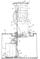
【図1】断面で示した燃料タンク内に一部嵌め込まれた状態の本発明による燃料送給ユニットの組立位置における概略の側面図である。
【図2】図1に示す燃料送給ユニットの組立位置における正面図である。
【図3】図1に示す燃料送給ユニットの組立中において一方のリザーバが既にタンク内の端位置に変位している状態を示す側面図である。
【図4】燃料送給ユニットがほぼタンク内に挿入されて最終的にタンク内で固定される前の状態を示す側面図である。
【図5】タンク内への取付が完了した状態の燃料送給ユニットを示す側面図である。
【図6】燃料送給ユニットの平面図である。
【図7】燃料送給ユニットの底面図である。
【図8】リザーバのスライドガイド部分の拡大側面図である。
【図9】図8のIX−IX線矢視図である。
【図10】図9のX−X線矢視断面図である。
【図11】図10のXI−XI線矢視断面図である。
【符号の説明】
1 燃料送給ユニット
2 第1リザーバ
3 燃料ポンプ
4 第2リザーバ
5 キャップ
6 燃料フィルタケース
7 燃料フィルタ
8 取付ホルダ
9 受容部
10 内筒
11 圧縮ばね
12 スライドガイド
13 スライド部材
14 端部ストッパー
15 タンク底面
16 燃料タンク
17 接続管路
18 接続ニップル
19 脚部
20 リザーバ底部
21 送出管路
22 圧力短管
23 分岐部
24 吸引ジェットポンプ
25 圧力制御弁
26 管路
27 噴出ノズル
28 捕捉ノズル
29 立上り管路
30 上縁
31 通路
32 組込穴
35 鍔部
36 液位センサ
37 段差部[0001]
BACKGROUND OF THE INVENTION
The present invention relates to a fuel supply unit for supplying fuel to an internal combustion engine such as an automobile engine.
[0002]
[Prior art]
A typical fuel delivery unit used for this type of purpose includes a mounting holder for fixedly supporting the unit, for example, by a compression spring or an elastic buffer member, with respect to the bottom of the fuel tank. The unit includes at least one reservoir, a fuel pump disposed within the reservoir, a fuel filter, if necessary, and a cap for closing a mounting hole provided in the tank for incorporating the unit into the fuel tank. And. Such a type of fuel delivery unit is known, for example, from European Patent Publication Nos. 0203244, 0297256, and German Published Patent No. 19615081.
[0003]
This type of fuel delivery unit can be installed and removed from the fuel tank as an integral assembly consisting of a reservoir or storage pot, a fuel pump, a fuel filter, and a fuel tank assembly hole closing cap. It must be able to be securely fixed to the inner bottom of the fuel tank. Such fuel delivery units must on the one hand be guaranteed a quick and reliable replacement of the entire unit during repair or maintenance, and on the other hand can be adapted to the high tank tolerances expected for the fuel tank used. Must. For this reason, at least the fuel supply pump in the unit, i.e. preferably the storage pot and the fuel pump arranged therein, can be slidably displaced in the axial direction with respect to the cap for closing the mounting hole or the cap flange. Various proposals have already been made to compensate for the tolerance of the high dimension in the tank by configuring the supply unit. For example, the fuel supply unit proposed in the above-mentioned European Patent Publication No. 0297256 is configured such that an electric fuel pump having a pressure line and a return line can be slid in the axial direction via an extendable guide. In addition, measures are taken to support the sound insulation of the fuel pump.
[0004]
By the way, as is well known, recent fuel tanks for automobiles have a structure with many branches, and there are only a few flat surfaces for caps for closing the built-in holes and cap flanges. Since the built-in space is also limited, it is inevitably the main requirement to make the fuel supply unit as compact as possible. However, on the other hand, it must be ensured that the reservoir belonging to the fuel delivery unit provides a sufficient discharge capacity for the fuel pump, i.e. the fuel storage volume, and the vehicle is traveling on a curved road. Alternatively, it is required to ensure a normal fuel supply to the internal combustion engine when in acceleration. In addition, the fuel storage volume in the reservoir is often used as a reserve volume, in which case the fuel level measurement system is one or more in the fuel tank when the main oil storage volume of the fuel tank is completely emptied. The main liquid level sensor is switched from the main liquid level sensor to the spare or sub liquid level sensor provided in the reservoir, thereby obtaining an indication of the remaining fuel level as accurately as possible from the limited volume of the reservoir. . In this case, it is desirable that the volume of the reservoir is as large as possible, but on the other hand, the mounting hole provided in the tank for incorporating the fuel supply unit into the tank has a certain specificity in order to obtain a perfect sealed state after installation. Taking this into account, increasing the volume of the reservoir requires that the fuel delivery unit be made as small as possible in order to make the mounting hole as small as possible. Contradicts with the request to not.
[0005]
Such a problem has already been mentioned, for example, in German Patent Publication No. 3225929. In this proposal, in order to solve such a problem, a reservoir as a storage pot or a surge pot is constituted by a plurality of parts that can be locked to each other on the tank bottom at the attachment completion position. In this case, one of the pot parts forms a holder for the fuel feeder assembly which is inserted into the tank following the pot. On the other hand, the fuel feeder assembly needs to be attached at a certain inclination angle with respect to the bottom of the fuel tank so that it can be used even in a tank having a relatively low structural height. However, such a reservoir design structure is difficult to adapt in the case of a fuel delivery unit of the type described above, rather the individual components of the reservoir and fuel delivery assembly must be assembled in a specific order. This will cause inconvenience.
[0006]
German Patent Publication No. 19528182 describes a fuel delivery unit with a liquid level sensor for incorporation into a fuel tank, in which a holder for receiving a fuel delivery device assembly slides and rotates in the axial direction. It is arranged on the flange of the tank so that In this design structure, the lower end of the holder of the fuel feeder assembly is pivotable on the inner bottom surface of the fuel tank or pot, and therefore the angle from the target position of the fuel tank flange and / or tank bottom surface. The measurement accuracy of the liquid level sensor arranged in the fuel supply unit is not affected by the deviation. In addition, this design structure includes a relatively large reservoir containing a fuel pump, and this reservoir is arranged to be rotatable and swingable via a spring element and is assembled with a fuel filter housed in a filter case. Is forming. The assembly of the fuel supply unit is performed in a configuration that substantially corresponds to the completed state of attachment. The arrangement of the individual parts in this case further requires a relatively large mounting hole in the tank, which is not desirable as mentioned above.
[0007]
Further, in the arrangement in which two fuel reservoirs are disclosed in European Patent Publication No. 0922603, which is incorporated in the fuel tank, each reservoir is interconnected flexibly through a flexible bar at one side and at the bottom. This flexible bar allows the two reservoirs to be relatively angled during assembly. The first reservoir first introduced into the tank is inserted into the tank mounting hole in an inclined state so that the upper end surface of the first reservoir first crosses the tank bottom surface. In order to place the first reservoir at the mounting completion position, it is necessary to turn the first reservoir 90 ° within the tank when the second reservoir, that is, the main reservoir is introduced into the tank mounting hole. In this case, the main reservoir must be tilted in the tank mounting hole. This means that the operation of introducing the arrangement configuration into the tank is extremely troublesome and time-consuming. After all, when rotating the reservoir introduced into the tank first, the reservoir to be introduced into the tank later must be tilted, so the inner width of the mounting hole must be selected to be correspondingly large. This is basically undesirable as described above.
[0008]
[Problems to be solved by the invention]
An object of the present invention is to solve the above-mentioned problems of the prior art, to always give a sufficient discharge capacity to the fuel pump, and to make the assembly hole of the fuel tank relatively small with a compact size. It is to provide a fuel delivery unit that can.
[0009]
[Means for Solving the Problems]
A fuel supply unit according to the present invention includes at least one first reservoir, a fuel pump disposed inside the first reservoir, and a cap that engages with a built-in hole provided in the fuel tank and closes the same. A first holder and a mounting holder for holding the cap, and the first reservoir together with the mounting holder. For introduction into the fuel tank When the cap is engaged with the mounting hole of the fuel tank by bringing it from the assembly position to the mounting position in the fuel tank through the mounting hole, the mounting holder is fixedly fixed to the bottom of the fuel tank by a compression spring or an elastic buffer member A fuel supply unit of a type that achieves the state, and in order to solve the above-described problem, in particular, the fuel supply unit further includes a second reservoir that is located laterally and communicated with the first reservoir at the assembly position, And second reservoir Both From the assembly position In the fuel tank through the mounting hole. While inserted into the mounting position Both reservoirs can move relative to each other along the axial direction of the mounting hole while keeping the axial direction of the reservoirs aligned with the axial direction of the mounting position. In the mounting position, the first and second reservoirs are laterally adjacent to each other, and at least one of the reservoirs is disposed at least partially protruding outside the axial projection surface of the cap in the mounting position. It is characterized by being.
[0010]
In the present invention, maintaining the state in which the first and second reservoirs are aligned in the axial direction means that the basic orientation in the axial direction of both reservoirs is the basic axial direction at the mounting position at the time of assembly or introduction into the tank. This means that it must match the target orientation. Such a configuration for the fuel delivery unit allows the individual assembly structures of the fuel delivery unit to be moved relative to each other, i.e. swiveled or axially displaced from the assembly position to the mounting position or vice versa. As a result, the fuel supply unit requires less space in the assembly position than in the installation position, and can be mounted in the tank through a relatively small mounting hole in the fuel tank. Further, since the component parts can be relatively moved toward the final attachment completion position in a state where the fuel supply unit is in the attachment position, the fuel supply unit is fixed on the tank bottom surface relatively than the assembly position. This can be done in a mounting position where a large space is provided.
[0011]
In a preferred embodiment of the invention, at least one reservoir, preferably the first reservoir, is guided axially movable on the mounting holder or the other reservoir and is spaced from its mounting hole closing cap for the purpose of installation. Can be changed. The resulting “extensible function” of the overall arrangement allows the fuel delivery unit component previously introduced into the tank to be moved to the mounting position prior to complete introduction of the entire unit.
[0012]
In still another preferred aspect of the present invention, the second reservoir is disposed inside the axial projection surface of the cap.
[0013]
Reservoir Relative along the axial direction of the mounting hole As a means for guiding the movement, for example, Between the first reservoir and the second reservoir Two slidable Na A slide member can be provided, and the extension dimension of this slide member is within the range of expansion of the inner diameter of the built-in hole of the reservoir which is inserted first into the built-in hole of the tank. Mounting hole axial center direction It is preferable to select it so that it can be moved to a mounting position while being shifted in a direction substantially orthogonal to. It goes without saying that a single slide member or three or more slide members may be used instead of providing two slide members.
[0014]
According to still another preferred aspect of the fuel supply unit according to the present invention, the slide member includes a guide rail having an end stopper, and one end of the guide rail is provided by the slide guide of the first reservoir and the other. The ends are guided by a slide guide of the second reservoir or a slide guide of the mounting holder so as to be axially slidable and torsionally rigid. This realizes the “extensible / retractable function” of the entire arrangement, and the end stopper of the guide rail makes it impossible for the slide guide to come off the guide rail, and at the same time restricts the upper limit of the extension amount. The first reservoir is surely pressed against the bottom of the tank by the second reservoir.
[0015]
According to still another preferred aspect of the present invention, the guide rail is configured as a deformed rail having an I-shaped cross section, and each slide guide holds a flange portion of the I-shaped deformed rail in a corresponding cross-sectional shape. It is configured as an irregularly shaped groove.
[0016]
According to still another preferred aspect of the present invention, the first and second reservoirs are in communication with each other via a soft connecting line on the bottom side, so that the liquid level of each reservoir is always at the same level. It is like that. The fuel feed pump, that is, the fuel feed assembly may be disposed in only one of the reservoirs. In this case, both reservoirs are discharged at the same liquid level with each other at the same time through the connection line. Is guaranteed to finish.
[0017]
However, it is also possible to place fuel supply assemblies in the respective reservoirs so that fuel is sent from both reservoirs to the engine, or fuel is sent from one reservoir to the other.
[0018]
According to a particularly preferred form of the fuel delivery unit of the invention, the connecting line between the two reservoirs extends substantially along the lower surface of each reservoir, in particular the connecting line is in an extended state, i.e. the unit is When in the assembly position, the connecting line is arranged so that it projects little or no from the axial projection plane of each reservoir. Thus, it is sufficient that the diameter of the tank mounting hole is selected to be a value slightly larger than the outer diameter of the reservoir to the extent that no support is generated in the assembling operation.
[0019]
According to still another preferred aspect of the present invention, the connection position of the connection pipe line to each reservoir is determined from the reservoir that houses the fuel pump when the tank is inclined and the liquid level in the reservoir is low. The position is selected so as to block the outflow of the fuel while allowing the fuel to flow into the reservoir from the other reservoir.
[0020]
According to still another preferred aspect of the present invention, a fuel filter is disposed between the cap and the two reservoirs, preferably the second reservoir, from a pressure control valve provided at the bottom of the fuel filter. Return fuel is fed into a second reservoir located below the cap. As a result, the space between the cap and the reservoir is optimally effectively utilized, and the fuel filter, that is, the fuel filter case and the second reservoir can be arranged in line with each other, for example, a pressure control valve connected to the fuel filter case. Can be inserted into the second reservoir in a fully assembled state.
[0021]
In this case, it is more preferable that the fuel filter is accommodated in the filter case, and the filter unit and the cap form one structural unit.
[0022]
According to a further preferred aspect of the present invention, the mounting holder constitutes a link that can expand and contract against the action of the compression spring in order to fix the entire structure on the bottom surface of the tank.
[0023]
The fuel supply unit according to the present invention may be configured such that the reservoirs are arranged on the mounting holder so as to be rotatable relative to each other. In this case, the cap and both reservoirs are aligned in the axial direction when in the assembly position. When arranged at the mounting position, one of the reservoirs, preferably the lowermost reservoir, is configured to be rotatable and axially movable at least with respect to the mounting holder. In that case, the reservoir arranged at the lowest position is introduced into the holder at the time of assembly via a wrench for a pivoting operation or a projection specially provided on the bottom of the tank as a receiving part for starting a pivoting telescopic motion. It is rotated by torque. Alternatively, each reservoir can be placed in a straight line with the spring bias and locking mechanism in the assembled position, and the final position adjustment to the installation complete position is locked. It is also possible to release the mechanism so that each component moves to the mounting completion position by the restoring force of the spring. In this case, it is necessary to provide additional means for fixing both reservoirs relative to each other at the attachment completion position. Then, the reservoir and cap disposed thereon, and possibly the filter case, are pushed together from above and folded, so that they can be brought into a final mounted state.
[0024]
The fuel supply unit of the present invention will be described based on the illustrated embodiment as follows.
[0025]
DETAILED DESCRIPTION OF THE INVENTION
As shown in FIGS. 1 and 2, the
[0026]
On the side facing the
[0027]
In the configuration of the
[0028]
The
[0029]
Furthermore, as can be seen in particular in the bottom view of FIG. 7, the connecting
[0030]
The function at the time of operation of the
[0031]
Another
[0032]
In particular, as shown in FIGS. 1 and 2, the
[0033]
For reasons of space, the
[0034]
The installation work of the
FIG. 1 shows a state in which the
[0035]
6 and 7 show a
[0036]
【The invention's effect】
As described above, the fuel supply unit according to the present invention further includes the second reservoir located at the side of the first reservoir at the assembly position and in communication with the first reservoir, and the first and second reservoirs are both From the assembly position In the fuel tank through the mounting hole of the fuel tank. While inserted into the mounting position Both reservoirs can move relative to each other along the axial direction of the mounting hole while keeping the axial direction of the reservoirs aligned with the axial direction of the mounting position. Supported by the mounting holder, in the mounting position, the first and second reservoirs are laterally adjacent to each other and at least one of the reservoirs protrudes at least partially outside the axial projection surface of the cap in the fuel tank. As a result, the individual assembly structures of the fuel delivery unit can be moved relative to each other, i.e. swiveled or axially displaced from the assembly position to the mounting position or vice versa. The feeding unit requires less space at the assembly position than when it is in the mounting position, and can be installed in the tank through a relatively small mounting hole in the fuel tank, and the fuel feeding unit is in the mounting position. The components can be moved relative to the final installation completion position at the bottom of the tank. The fuel tank can be fixed at a mounting position where a relatively larger space is provided than the assembly position. The fuel pump always has a sufficient discharge capacity, and is compact and compares the fuel tank mounting holes. It is possible to provide a fuel supply unit that can be made smaller.
[Brief description of the drawings]
FIG. 1 is a schematic side view of an assembly position of a fuel supply unit according to the present invention in a state of being partially fitted in a fuel tank shown in cross section.
FIG. 2 is a front view of the fuel supply unit shown in FIG. 1 at the assembly position.
3 is a side view showing a state in which one reservoir has already been displaced to an end position in a tank during assembly of the fuel supply unit shown in FIG. 1;
FIG. 4 is a side view showing a state before the fuel supply unit is almost inserted into the tank and finally fixed in the tank.
FIG. 5 is a side view showing the fuel supply unit in a state where the attachment in the tank is completed.
FIG. 6 is a plan view of a fuel supply unit.
FIG. 7 is a bottom view of the fuel supply unit.
FIG. 8 is an enlarged side view of a slide guide portion of the reservoir.
9 is a view taken along line IX-IX in FIG.
10 is a cross-sectional view taken along line XX in FIG.
11 is a cross-sectional view taken along line XI-XI in FIG.
[Explanation of symbols]
1 Fuel supply unit
2 First reservoir
3 Fuel pump
4 Second reservoir
5 Cap
6 Fuel filter case
7 Fuel filter
8 Mounting holder
9 Receptor
10 Inner cylinder
11 Compression spring
12 Slide guide
13 Slide member
14 End stopper
15 Tank bottom
16 Fuel tank
17 Connection pipeline
18 Connection nipple
19 Leg
20 Reservoir bottom
21 Delivery pipeline
22 Pressure short pipe
23 Branch
24 Suction jet pump
25 Pressure control valve
26 pipeline
27 Ejection nozzle
28 Capture nozzle
29 Rising pipeline
30 Upper edge
31 passage
32 mounting holes
35 Buttocks
36 Liquid level sensor
37 steps
Claims (14)
Applications Claiming Priority (2)
| Application Number | Priority Date | Filing Date | Title |
|---|---|---|---|
| DE10027991.0 | 2000-06-08 | ||
| DE10027991A DE10027991B4 (en) | 2000-06-08 | 2000-06-08 | Fuel delivery unit |
Publications (2)
| Publication Number | Publication Date |
|---|---|
| JP2002029272A JP2002029272A (en) | 2002-01-29 |
| JP4320134B2 true JP4320134B2 (en) | 2009-08-26 |
Family
ID=7644874
Family Applications (1)
| Application Number | Title | Priority Date | Filing Date |
|---|---|---|---|
| JP2001173839A Expired - Fee Related JP4320134B2 (en) | 2000-06-08 | 2001-06-08 | Fuel supply unit |
Country Status (5)
| Country | Link |
|---|---|
| US (1) | US6640832B2 (en) |
| EP (1) | EP1162100B1 (en) |
| JP (1) | JP4320134B2 (en) |
| CA (1) | CA2349722C (en) |
| DE (2) | DE10027991B4 (en) |
Families Citing this family (28)
| Publication number | Priority date | Publication date | Assignee | Title |
|---|---|---|---|---|
| DE10161403B4 (en) * | 2001-12-13 | 2007-03-29 | Siemens Ag | Fuel delivery unit |
| DE10229803B4 (en) * | 2002-07-03 | 2006-07-27 | Eurocopter Deutschland Gmbh | Connecting arrangement for releasably connecting a first flexible tank with a second flexible tank of an aircraft |
| US6886541B2 (en) * | 2003-02-25 | 2005-05-03 | Denso International America, Inc. | Fuel pump module and method of assembly |
| DE10330452A1 (en) * | 2003-07-05 | 2005-02-24 | Daimlerchrysler Ag | Holding device for fixing a fuel pump in a swirl pot |
| GB2410477B (en) * | 2004-01-29 | 2006-01-25 | Visteon Global Tech Inc | Fuel delivery module assembly |
| EP1577145B8 (en) * | 2004-03-17 | 2010-10-13 | Delphi Technologies, Inc. | Reservoir and Filter assembly |
| US20060000454A1 (en) * | 2004-07-02 | 2006-01-05 | Visteon Global Technologies, Inc. | In-tank fuel supply unit having long life filter |
| JP4329037B2 (en) * | 2004-12-28 | 2009-09-09 | 株式会社デンソー | Fuel supply device |
| US7571716B2 (en) * | 2005-03-14 | 2009-08-11 | Inergy Automotive Systems Research (Societe Anonyme) | Fuel system with direct connection between fuel pump, jet pump, and fuel filter |
| FR2885179B1 (en) * | 2005-04-27 | 2007-10-12 | Ti Fuel Systems Sas Soc Par Ac | ASSEMBLY COMPRISING A PICKUP MODULE AND ACTIVE CHARCOAL FILTER FOR FUEL RESERVOIR OF MOTOR VEHICLE |
| JP4356897B2 (en) * | 2005-06-07 | 2009-11-04 | 株式会社デンソー | Fuel supply device |
| US7556024B2 (en) * | 2005-09-22 | 2009-07-07 | Ti Group Automotive Systems, L.L.C. | Fuel supply module |
| US20070163659A1 (en) * | 2006-01-17 | 2007-07-19 | Honda Motor Co., Ltd. | Fuel tank |
| JP4979350B2 (en) * | 2006-11-10 | 2012-07-18 | 愛三工業株式会社 | Fuel pump unit, fuel pump module, fuel supply device, and fuel tank unit including any of these |
| DE102007032271A1 (en) * | 2007-07-11 | 2009-01-15 | Continental Automotive Gmbh | Fuel feed unit for application in fuel tank of motor vehicle, has two modules, each comprising opening at its base region for fluidic connection with other module, where openings are similar |
| DE102008027830B4 (en) * | 2008-06-11 | 2014-11-06 | Kautex Textron Gmbh & Co. Kg | Fuel tank and method of servicing a fuel tank |
| KR101153286B1 (en) * | 2010-03-24 | 2012-06-07 | 주식회사 코아비스 | The in-tank filter of fuel pump moudle |
| KR101121582B1 (en) | 2010-07-01 | 2012-03-06 | 현담산업 주식회사 | Fuel pump a module for auxiliary cup is form increase to fuel charge quantity |
| KR101121581B1 (en) | 2010-07-01 | 2012-03-06 | 현담산업 주식회사 | Fuel pump a module to increase for fuel charge quantity |
| JP5327253B2 (en) * | 2011-03-23 | 2013-10-30 | 株式会社デンソー | Fuel supply device |
| DE102011082418A1 (en) | 2010-09-13 | 2012-03-15 | Denso Corporation | FUEL SUPPLY DEVICE |
| CN103850838A (en) * | 2010-09-13 | 2014-06-11 | 株式会社电装 | Fuel supply apparatus |
| US8372278B1 (en) * | 2012-03-21 | 2013-02-12 | GM Global Technology Operations LLC | Liquid fuel strainer assembly |
| US9938942B2 (en) * | 2012-05-22 | 2018-04-10 | Robert Bosch Gmbh | Fuel supply system |
| US9556837B2 (en) * | 2014-05-13 | 2017-01-31 | Robert Bosch Gmbh | Spring loaded component mounting within fuel tank |
| DE102015209411A1 (en) * | 2015-05-22 | 2016-11-24 | Ford Global Technologies, Llc | Conveying module for conveying fuel |
| JP6695707B2 (en) | 2016-02-19 | 2020-05-20 | 愛三工業株式会社 | Fuel supply device |
| JP7271383B2 (en) * | 2019-09-30 | 2023-05-11 | 愛三工業株式会社 | FUEL PUMP MODULE, FUEL SUPPLY DEVICE, AND METHOD OF INSTALLING FUEL PUMP MODULE ON FUEL TANK |
Family Cites Families (11)
| Publication number | Priority date | Publication date | Assignee | Title |
|---|---|---|---|---|
| DE3225929C2 (en) * | 1982-07-10 | 1994-01-20 | Bosch Gmbh Robert | Fuel tanks for internal combustion engines, in particular motor vehicles |
| EP0203244B1 (en) * | 1985-05-25 | 1988-09-21 | FIAT AUTO S.p.A. | System for fixing the fuel pump in the fuel tank |
| DE3721977C2 (en) * | 1987-07-03 | 1997-02-06 | Pierburg Ag | Fuel delivery unit |
| DE19524034B4 (en) * | 1995-07-01 | 2006-08-10 | Siemens Ag | Fuel-conveying device |
| DE19528182B4 (en) * | 1995-08-01 | 2005-03-03 | Robert Bosch Gmbh | Fuel delivery |
| DE19615081A1 (en) | 1996-04-17 | 1997-10-23 | Bosch Gmbh Robert | IC engine fuel supply device including fuel tank containing pump module |
| DE19627578A1 (en) * | 1996-07-09 | 1998-01-15 | Pierburg Ag | Arrangement for saddle tank for fuel tanker vehicle |
| FR2771972B1 (en) * | 1997-12-10 | 2000-02-25 | Marwal Systems | RESERVE DEVICE FOR A MOTOR VEHICLE FUEL TANK |
| DE19932356B4 (en) * | 1998-08-10 | 2010-03-18 | Continental Automotive Gmbh | Fuel supply system |
| DE19912642C2 (en) * | 1999-03-20 | 2001-07-05 | Kautex Textron Gmbh & Co Kg | Fuel tank for a motor vehicle |
| US6436287B1 (en) * | 2000-12-20 | 2002-08-20 | Robert Bosch Corportion | Fuel pump module and method for installing the same |
-
2000
- 2000-06-08 DE DE10027991A patent/DE10027991B4/en not_active Expired - Fee Related
-
2001
- 2001-05-04 EP EP01110805A patent/EP1162100B1/en not_active Expired - Lifetime
- 2001-05-04 DE DE50113310T patent/DE50113310D1/en not_active Expired - Lifetime
- 2001-06-06 CA CA002349722A patent/CA2349722C/en not_active Expired - Fee Related
- 2001-06-06 US US09/875,226 patent/US6640832B2/en not_active Expired - Fee Related
- 2001-06-08 JP JP2001173839A patent/JP4320134B2/en not_active Expired - Fee Related
Also Published As
| Publication number | Publication date |
|---|---|
| JP2002029272A (en) | 2002-01-29 |
| CA2349722C (en) | 2005-04-12 |
| DE10027991B4 (en) | 2005-11-10 |
| EP1162100A3 (en) | 2006-04-19 |
| DE50113310D1 (en) | 2008-01-10 |
| US6640832B2 (en) | 2003-11-04 |
| EP1162100B1 (en) | 2007-11-28 |
| CA2349722A1 (en) | 2001-12-08 |
| DE10027991A1 (en) | 2001-12-20 |
| EP1162100A2 (en) | 2001-12-12 |
| US20010050107A1 (en) | 2001-12-13 |
Similar Documents
| Publication | Publication Date | Title |
|---|---|---|
| JP4320134B2 (en) | Fuel supply unit | |
| JP6162183B2 (en) | Fuel supply device | |
| RU2499689C2 (en) | Fueling device | |
| US6923164B1 (en) | Fuel supply apparatus | |
| CN106574585B (en) | Fuel supply system | |
| CN100443335C (en) | Headlamp cleaner | |
| US7066153B2 (en) | Jet pump with improved start-up properties and fuel delivery system equipped with such jet pump | |
| JP6840895B2 (en) | Fuel tank lid | |
| US6436287B1 (en) | Fuel pump module and method for installing the same | |
| US9701194B2 (en) | Fuel-dispensing nozzle inhibitor | |
| US20070062493A1 (en) | Fuel supply module | |
| EP3224076B1 (en) | A fuel storage system | |
| JP2017008761A (en) | Fuel tank | |
| US7100645B2 (en) | Filler pipe structure | |
| US20080149199A1 (en) | Saddle tank | |
| US8992190B2 (en) | Fuel feed apparatus | |
| JP2000052789A (en) | Filling device of fuel tank | |
| CN106662061A (en) | Fuel injection system having an assembly for joining a fuel injection valve with a fuel conveying component | |
| US10094344B2 (en) | Fuel supply device | |
| JP3760852B2 (en) | Fuel supply device in the fuel tank | |
| JP5276872B2 (en) | Fuel supply device | |
| JP4767697B2 (en) | Fuel tank | |
| JP2007190951A (en) | Fuel tank | |
| KR200213416Y1 (en) | A reservoir of fuel tank | |
| KR100401444B1 (en) | A reservoir of fuel tank |
Legal Events
| Date | Code | Title | Description |
|---|---|---|---|
| A621 | Written request for application examination |
Free format text: JAPANESE INTERMEDIATE CODE: A621 Effective date: 20060208 |
|
| RD02 | Notification of acceptance of power of attorney |
Free format text: JAPANESE INTERMEDIATE CODE: A7422 Effective date: 20060309 |
|
| A131 | Notification of reasons for refusal |
Free format text: JAPANESE INTERMEDIATE CODE: A131 Effective date: 20080626 |
|
| A601 | Written request for extension of time |
Free format text: JAPANESE INTERMEDIATE CODE: A601 Effective date: 20080925 |
|
| A602 | Written permission of extension of time |
Free format text: JAPANESE INTERMEDIATE CODE: A602 Effective date: 20081001 |
|
| A601 | Written request for extension of time |
Free format text: JAPANESE INTERMEDIATE CODE: A601 Effective date: 20081027 |
|
| A602 | Written permission of extension of time |
Free format text: JAPANESE INTERMEDIATE CODE: A602 Effective date: 20081030 |
|
| A601 | Written request for extension of time |
Free format text: JAPANESE INTERMEDIATE CODE: A601 Effective date: 20081126 |
|
| A602 | Written permission of extension of time |
Free format text: JAPANESE INTERMEDIATE CODE: A602 Effective date: 20081201 |
|
| A521 | Request for written amendment filed |
Free format text: JAPANESE INTERMEDIATE CODE: A523 Effective date: 20081226 |
|
| TRDD | Decision of grant or rejection written | ||
| A01 | Written decision to grant a patent or to grant a registration (utility model) |
Free format text: JAPANESE INTERMEDIATE CODE: A01 Effective date: 20090513 |
|
| A01 | Written decision to grant a patent or to grant a registration (utility model) |
Free format text: JAPANESE INTERMEDIATE CODE: A01 |
|
| A61 | First payment of annual fees (during grant procedure) |
Free format text: JAPANESE INTERMEDIATE CODE: A61 Effective date: 20090601 |
|
| FPAY | Renewal fee payment (event date is renewal date of database) |
Free format text: PAYMENT UNTIL: 20120605 Year of fee payment: 3 |
|
| R150 | Certificate of patent or registration of utility model |
Free format text: JAPANESE INTERMEDIATE CODE: R150 |
|
| LAPS | Cancellation because of no payment of annual fees |