JP2017008761A - Fuel tank - Google Patents

Fuel tank Download PDF

Info

Publication number
JP2017008761A
JP2017008761A JP2015123136A JP2015123136A JP2017008761A JP 2017008761 A JP2017008761 A JP 2017008761A JP 2015123136 A JP2015123136 A JP 2015123136A JP 2015123136 A JP2015123136 A JP 2015123136A JP 2017008761 A JP2017008761 A JP 2017008761A
Authority
JP
Japan
Prior art keywords
pump unit
tank
guide
tank body
lock
Prior art date
Legal status (The legal status is an assumption and is not a legal conclusion. Google has not performed a legal analysis and makes no representation as to the accuracy of the status listed.)
Pending
Application number
JP2015123136A
Other languages
Japanese (ja)
Inventor
池谷 昌紀
Masanori Iketani
昌紀 池谷
Current Assignee (The listed assignees may be inaccurate. Google has not performed a legal analysis and makes no representation or warranty as to the accuracy of the list.)
Aisan Industry Co Ltd
Original Assignee
Aisan Industry Co Ltd
Priority date (The priority date is an assumption and is not a legal conclusion. Google has not performed a legal analysis and makes no representation as to the accuracy of the date listed.)
Filing date
Publication date
Application filed by Aisan Industry Co Ltd filed Critical Aisan Industry Co Ltd
Priority to JP2015123136A priority Critical patent/JP2017008761A/en
Priority to US15/185,342 priority patent/US9752543B2/en
Publication of JP2017008761A publication Critical patent/JP2017008761A/en
Pending legal-status Critical Current

Links

Images

Classifications

    • FMECHANICAL ENGINEERING; LIGHTING; HEATING; WEAPONS; BLASTING
    • F02COMBUSTION ENGINES; HOT-GAS OR COMBUSTION-PRODUCT ENGINE PLANTS
    • F02MSUPPLYING COMBUSTION ENGINES IN GENERAL WITH COMBUSTIBLE MIXTURES OR CONSTITUENTS THEREOF
    • F02M37/00Apparatus or systems for feeding liquid fuel from storage containers to carburettors or fuel-injection apparatus; Arrangements for purifying liquid fuel specially adapted for, or arranged on, internal-combustion engines
    • F02M37/0047Layout or arrangement of systems for feeding fuel
    • FMECHANICAL ENGINEERING; LIGHTING; HEATING; WEAPONS; BLASTING
    • F02COMBUSTION ENGINES; HOT-GAS OR COMBUSTION-PRODUCT ENGINE PLANTS
    • F02MSUPPLYING COMBUSTION ENGINES IN GENERAL WITH COMBUSTIBLE MIXTURES OR CONSTITUENTS THEREOF
    • F02M37/00Apparatus or systems for feeding liquid fuel from storage containers to carburettors or fuel-injection apparatus; Arrangements for purifying liquid fuel specially adapted for, or arranged on, internal-combustion engines
    • F02M37/0076Details of the fuel feeding system related to the fuel tank
    • FMECHANICAL ENGINEERING; LIGHTING; HEATING; WEAPONS; BLASTING
    • F02COMBUSTION ENGINES; HOT-GAS OR COMBUSTION-PRODUCT ENGINE PLANTS
    • F02MSUPPLYING COMBUSTION ENGINES IN GENERAL WITH COMBUSTIBLE MIXTURES OR CONSTITUENTS THEREOF
    • F02M37/00Apparatus or systems for feeding liquid fuel from storage containers to carburettors or fuel-injection apparatus; Arrangements for purifying liquid fuel specially adapted for, or arranged on, internal-combustion engines
    • F02M37/04Feeding by means of driven pumps
    • F02M37/08Feeding by means of driven pumps electrically driven
    • F02M37/10Feeding by means of driven pumps electrically driven submerged in fuel, e.g. in reservoir
    • F02M37/103Mounting pumps on fuel tanks
    • FMECHANICAL ENGINEERING; LIGHTING; HEATING; WEAPONS; BLASTING
    • F02COMBUSTION ENGINES; HOT-GAS OR COMBUSTION-PRODUCT ENGINE PLANTS
    • F02MSUPPLYING COMBUSTION ENGINES IN GENERAL WITH COMBUSTIBLE MIXTURES OR CONSTITUENTS THEREOF
    • F02M37/00Apparatus or systems for feeding liquid fuel from storage containers to carburettors or fuel-injection apparatus; Arrangements for purifying liquid fuel specially adapted for, or arranged on, internal-combustion engines
    • F02M37/04Feeding by means of driven pumps
    • F02M37/08Feeding by means of driven pumps electrically driven
    • F02M37/10Feeding by means of driven pumps electrically driven submerged in fuel, e.g. in reservoir
    • F02M37/106Feeding by means of driven pumps electrically driven submerged in fuel, e.g. in reservoir the pump being installed in a sub-tank
    • FMECHANICAL ENGINEERING; LIGHTING; HEATING; WEAPONS; BLASTING
    • F02COMBUSTION ENGINES; HOT-GAS OR COMBUSTION-PRODUCT ENGINE PLANTS
    • F02MSUPPLYING COMBUSTION ENGINES IN GENERAL WITH COMBUSTIBLE MIXTURES OR CONSTITUENTS THEREOF
    • F02M37/00Apparatus or systems for feeding liquid fuel from storage containers to carburettors or fuel-injection apparatus; Arrangements for purifying liquid fuel specially adapted for, or arranged on, internal-combustion engines
    • F02M37/02Feeding by means of suction apparatus, e.g. by air flow through carburettors
    • F02M37/025Feeding by means of a liquid fuel-driven jet pump
    • FMECHANICAL ENGINEERING; LIGHTING; HEATING; WEAPONS; BLASTING
    • F02COMBUSTION ENGINES; HOT-GAS OR COMBUSTION-PRODUCT ENGINE PLANTS
    • F02MSUPPLYING COMBUSTION ENGINES IN GENERAL WITH COMBUSTIBLE MIXTURES OR CONSTITUENTS THEREOF
    • F02M37/00Apparatus or systems for feeding liquid fuel from storage containers to carburettors or fuel-injection apparatus; Arrangements for purifying liquid fuel specially adapted for, or arranged on, internal-combustion engines
    • F02M37/04Feeding by means of driven pumps
    • F02M37/08Feeding by means of driven pumps electrically driven
    • F02M37/10Feeding by means of driven pumps electrically driven submerged in fuel, e.g. in reservoir
    • FMECHANICAL ENGINEERING; LIGHTING; HEATING; WEAPONS; BLASTING
    • F02COMBUSTION ENGINES; HOT-GAS OR COMBUSTION-PRODUCT ENGINE PLANTS
    • F02MSUPPLYING COMBUSTION ENGINES IN GENERAL WITH COMBUSTIBLE MIXTURES OR CONSTITUENTS THEREOF
    • F02M37/00Apparatus or systems for feeding liquid fuel from storage containers to carburettors or fuel-injection apparatus; Arrangements for purifying liquid fuel specially adapted for, or arranged on, internal-combustion engines
    • F02M37/22Arrangements for purifying liquid fuel specially adapted for, or arranged on, internal-combustion engines, e.g. arrangements in the feeding system
    • F02M37/32Arrangements for purifying liquid fuel specially adapted for, or arranged on, internal-combustion engines, e.g. arrangements in the feeding system characterised by filters or filter arrangements
    • F02M37/34Arrangements for purifying liquid fuel specially adapted for, or arranged on, internal-combustion engines, e.g. arrangements in the feeding system characterised by filters or filter arrangements by the filter structure, e.g. honeycomb, mesh or fibrous
    • FMECHANICAL ENGINEERING; LIGHTING; HEATING; WEAPONS; BLASTING
    • F02COMBUSTION ENGINES; HOT-GAS OR COMBUSTION-PRODUCT ENGINE PLANTS
    • F02MSUPPLYING COMBUSTION ENGINES IN GENERAL WITH COMBUSTIBLE MIXTURES OR CONSTITUENTS THEREOF
    • F02M37/00Apparatus or systems for feeding liquid fuel from storage containers to carburettors or fuel-injection apparatus; Arrangements for purifying liquid fuel specially adapted for, or arranged on, internal-combustion engines
    • F02M37/22Arrangements for purifying liquid fuel specially adapted for, or arranged on, internal-combustion engines, e.g. arrangements in the feeding system
    • F02M37/32Arrangements for purifying liquid fuel specially adapted for, or arranged on, internal-combustion engines, e.g. arrangements in the feeding system characterised by filters or filter arrangements
    • F02M37/50Filters arranged in or on fuel tanks

Abstract

PROBLEM TO BE SOLVED: To provide a fuel tank that enables improvement of attachment performance of a pump unit to a tank body.SOLUTION: A fuel tank 10 includes: a tank body 12 having a tank hole 22; a sub tank 14 provided at a bottom of the tank body 12; and a pump unit 16 inserted from the tank hole 22 and thus attached to the sub tank 14. The fuel tank further includes guide means for guiding the pump unit 16 from the tank hole 22 side of the tank body 12 to the attachment position on the bottom side. The guide means comprises: a guide rail 55 provided in the tank body 12; and guide pins 51, 53 provided in the pump unit 16 and slidably engaged with the guide rail 55.SELECTED DRAWING: Figure 1

Description

本発明は、内燃機関用の燃料を貯留するタンク本体と、タンク本体内の燃料を内燃機関に圧送する燃料ポンプを有するポンプユニットとを備える燃料タンクに関する。   The present invention relates to a fuel tank including a tank body that stores fuel for an internal combustion engine, and a pump unit that has a fuel pump that pumps fuel in the tank body to the internal combustion engine.

従来の燃料タンクには、例えば特許文献1に記載されたものがある。特許文献1の燃料タンクは、タンク本体とブラケットとポンプユニットとを備えている。タンク本体は、上面部に開口部を有している。ブラケットは、タンク本体の底部に設けられている。ポンプユニットは、ブラケットに軸方向を横向きとする横置き状態で配置される燃料ポンプ、及び、燃料ポンプを保持するポンプ保持部材を有している。ポンプユニットは、タンク本体の開口部からの挿入によりブラケットに組付けられている。   Conventional fuel tanks include those described in Patent Document 1, for example. The fuel tank of Patent Document 1 includes a tank body, a bracket, and a pump unit. The tank main body has an opening on the upper surface. The bracket is provided at the bottom of the tank body. The pump unit includes a fuel pump that is disposed in a horizontal state in which the axial direction is sideways on the bracket, and a pump holding member that holds the fuel pump. The pump unit is assembled to the bracket by insertion from the opening of the tank body.

特開2003−172217号公報JP 2003-172217 A

特許文献1によると、ポンプユニットをサブタンクに組付ける作業は、一般的に作業者の手作業で行われる。しかし、タンク本体の開口部の開口面積は比較的小さい。また、タンク本体の内部が暗くて見にくい。また、タンク本体の開口部からブラケットまでが遠い。したがって、ポンプユニットをタンク本体の開口部から挿入してブラケットに組付ける際に、ブラケットの位置がわかり難いため、作業時間が長くかかったり、ポンプユニットの組付け不良を招いたりする場合がある。このため、タンク本体に対するポンプユニットの組付け性が悪いという問題があった。本発明が解決しようとする課題は、タンク本体に対するポンプユニットの組付け性を向上することのできる燃料タンクを提供することにある。   According to Patent Document 1, the operation of assembling the pump unit to the sub tank is generally performed manually by the operator. However, the opening area of the opening of the tank body is relatively small. Also, the inside of the tank body is dark and difficult to see. Also, the distance from the opening of the tank body to the bracket is far. Therefore, when the pump unit is inserted from the opening of the tank main body and assembled to the bracket, the position of the bracket is difficult to understand, and therefore it may take a long time to work or may cause poor assembly of the pump unit. For this reason, there existed a problem that the assembly | attachment property of the pump unit with respect to a tank main body was bad. The problem to be solved by the present invention is to provide a fuel tank that can improve the assembly of the pump unit to the tank body.

第1の発明は、開口部を有するタンク本体と、燃料ポンプ、及び、燃料ポンプを保持するポンプ保持部材を有し、かつ、前記開口部から前記タンク本体の底部側に配置されるポンプユニットと、を備える燃料タンクであって、前記ポンプユニットを前記タンク本体の開口部側から底部側の組付け位置までガイドするガイド手段を備え、前記ガイド手段は、前記タンク本体側に設けられるガイドレールと、前記ポンプユニット側に設けられかつ前記ガイドレールに摺動可能に係合される摺動子とにより構成されている。この構成によると、タンク本体内にポンプユニットを組付ける際に、ガイド手段のガイドレールによって摺動子がガイドされることによって、ポンプユニットがタンク本体の開口部側から底部側の組付け位置までガイドされる。したがって、ポンプユニットを迷わずに容易に組付け位置へ適正に移動させることができる。このため、作業時間を短縮するとともに、ポンプユニットの組付け不良を抑制することができる。よって、タンク本体に対するポンプユニットの組付け性を向上することができる。   A first invention includes a tank body having an opening, a fuel pump, and a pump holding member that holds the fuel pump, and a pump unit disposed on the bottom side of the tank body from the opening. And a guide means for guiding the pump unit from an opening side of the tank body to an assembly position on the bottom side, the guide means being a guide rail provided on the tank body side; The slider is provided on the pump unit side and is slidably engaged with the guide rail. According to this configuration, when the pump unit is assembled in the tank body, the pump unit is guided from the opening side of the tank body to the assembly position on the bottom side by being guided by the guide rail of the guide means. Guided. Therefore, the pump unit can be easily moved appropriately to the assembly position without hesitation. For this reason, while shortening working time, the assembly | attachment defect of a pump unit can be suppressed. Therefore, the assembly property of the pump unit to the tank body can be improved.

第2の発明は、第1の発明において、前記ガイド手段は、前記ポンプユニットの両側に配置されている。この構成によると、ポンプユニットが両ガイド手段によってガイドされるため、タンク本体に対するポンプユニットの組付け性を向上することができる。   In a second aspect based on the first aspect, the guide means is disposed on both sides of the pump unit. According to this configuration, since the pump unit is guided by the both guide means, the assembling property of the pump unit to the tank body can be improved.

第3の発明は、第1又は2の発明において、前記タンク本体の底部には、前記燃料ポンプに吸入される燃料を貯留するサブタンクが設けられ、前記ガイドレールは、前記サブタンクの水平状態での燃料を貯留可能な高さ位置よりも上方へ延出されている。この構成によると、サブタンクの水平状態での燃料を貯留可能な高さ位置よりも高い位置からガイドレールによって摺動子をガイドすることができる。   According to a third invention, in the first or second invention, a sub-tank for storing fuel sucked into the fuel pump is provided at a bottom portion of the tank body, and the guide rail is in a horizontal state of the sub-tank. It extends upward from a height position where fuel can be stored. According to this configuration, the slider can be guided by the guide rail from a position higher than the height position at which the fuel in the horizontal state of the sub tank can be stored.

第4の発明は、第1又は2の発明において、前記タンク本体内に挿入された前記ポンプユニットの長手方向の一端部を回動可能に支持する回動支持手段を備え、前記回動支持手段は、前記タンク本体側に設けられたタンク本体側支持部と、前記ポンプユニット側に設けられかつ前記タンク本体側支持部に係合されるポンプユニット側支持部とにより構成され、前記ガイドレールには、前記タンク本体の開口部側から底部側に延在する第1ガイド部が設けられている。この構成によると、ガイドレールの第1ガイド部により、ポンプユニットの摺動子をタンク本体の開口部側から底部側にガイドすることができる。また、回動支持手段のタンク本体側支持部とポンプユニット側支持部との係合により、ポンプユニットの長手方向の一端部を回動可能に支持することができる。よって、回動支持手段を回動支点として、ポンプユニットをタンク本体の底部側の組付け位置に容易に回動させることができる。   4th invention is the 1st or 2nd invention, The rotation support means which supports the one end part of the longitudinal direction of the said pump unit inserted in the said tank main body so that rotation is possible, The said rotation support means Is constituted by a tank body side support portion provided on the tank body side, and a pump unit side support portion provided on the pump unit side and engaged with the tank body side support portion. Is provided with a first guide portion extending from the opening side to the bottom side of the tank body. According to this configuration, the slider of the pump unit can be guided from the opening side of the tank body to the bottom side by the first guide portion of the guide rail. Further, the one end portion in the longitudinal direction of the pump unit can be rotatably supported by the engagement of the tank body side support portion and the pump unit side support portion of the rotation support means. Therefore, the pump unit can be easily rotated to the assembly position on the bottom side of the tank body using the rotation support means as a rotation fulcrum.

第5の発明は、第4の発明において、前記第1ガイド部の底部側端部に連続され、前記回動支持手段を回動支点として前記ポンプユニットを下方へ回動させる際に前記摺動子をガイドする第2ガイド部が設けられている。この構成によると、回動支持手段を回動支点としてポンプユニットを回動させることにより、摺動子がガイドレールの第2ガイド部によりガイドされる。このため、ポンプユニットをタンク本体の底部側の組付け位置に容易に移動させることができる。   According to a fifth invention, in the fourth invention, the sliding is continued when the pump unit is rotated downward with the rotation support means as a rotation fulcrum, which is continuous with the bottom side end of the first guide portion. A second guide portion for guiding the child is provided. According to this configuration, the slider is guided by the second guide portion of the guide rail by rotating the pump unit with the rotation support means as the rotation fulcrum. For this reason, the pump unit can be easily moved to the assembly position on the bottom side of the tank body.

第6の発明は、第5の発明において、前記ガイドレールの第2ガイド部の曲率半径は、下方に向かって次第に小さくなるように設定され、前記摺動子側の部材は、前記摺動子が前記第2ガイド部を下方に摺動した際に弾性変形可能に形成され、前記第2ガイド部には、前記ポンプユニットを前記タンク本体の底部側の組付け位置に回動したときに、前記摺動子側の部材の弾性復元により前記摺動子を係合するロック部が設けられている。この構成によると、摺動子がガイドレールの第2ガイド部を摺動した際に、摺動子側の部材が弾性変形する。そして、ポンプユニットをタンク本体の底部側の組付け位置に回動したときには、摺動子側の部材の弾性復元により、第2ガイド部のロック部に摺動子が係合することによって、タンク本体にポンプユニットがロックされる。すなわち、第2ガイド部のロック部と摺動子とにより、タンク本体にポンプユニットをロックするロック手段が構成されている。また、摺動子側の部材の弾性を利用して、第2ガイド部のロック部に対する摺動子の係合を解除することによって、ポンプユニットを挿入時とは逆順で取外すことができる。よって、ポンプユニットをタンク本体に着脱可能に組付けることができる。また、第2ガイド部のロック部と摺動子とによりロック手段が構成されるため、ロック手段に特別な部材を設けなくて済む。   In a sixth aspect based on the fifth aspect, the radius of curvature of the second guide portion of the guide rail is set so as to gradually decrease downward, and the member on the slider side is the slider. Is formed to be elastically deformable when sliding downward on the second guide portion, and when the pump unit is rotated to the assembly position on the bottom side of the tank body on the second guide portion, A lock portion for engaging the slider is provided by elastic restoration of the member on the slider side. According to this configuration, when the slider slides on the second guide portion of the guide rail, the member on the slider side is elastically deformed. When the pump unit is rotated to the assembly position on the bottom side of the tank body, the slider engages with the lock portion of the second guide portion by elastic restoration of the member on the slider side. The pump unit is locked to the main body. That is, the lock part which locks a pump unit to a tank main body is comprised by the lock part and slider of a 2nd guide part. Further, by releasing the engagement of the slider with the lock portion of the second guide portion using the elasticity of the member on the slider side, the pump unit can be removed in the reverse order of insertion. Therefore, the pump unit can be detachably assembled to the tank body. Further, since the lock means is constituted by the lock portion of the second guide portion and the slider, it is not necessary to provide a special member for the lock means.

第7の発明は、第4又は5の発明において、前記タンク本体と前記ポンプユニットとの間には、前記回動支持手段を回動支点として前記ポンプユニットを前記タンク本体の底部側の組付け位置に回動したときに、相互に係合するロック手段が設けられ、前記ロック手段は、前記タンク本体側に設けられたタンク本体側ロック部と、前記ポンプユニット側に設けられかつ前記タンク本体側ロック部に係合されるポンプユニット側ロック部とを備え、前記タンク本体側ロック部と前記ポンプユニット側ロック部とは、少なくとも一方の弾性変形を利用して係合可能に構成されている。この構成によると、ポンプユニットをタンク本体の底部側の組付け位置に回動したときには、ロック手段のタンク本体側ロック部にポンプユニット側ロック部が少なくとも一方の弾性変形を利用して係合することによって、タンク本体にポンプユニットがロックされる。また、タンク本体側ロック部に対するポンプユニット側ロック部の係合を少なくとも一方の弾性変形を利用して解除することによって、ポンプユニットを挿入時とは逆順で取外すことができる。よって、ポンプユニットをタンク本体に着脱可能に組付けることができる。   According to a seventh invention, in the fourth or fifth invention, the pump unit is assembled on the bottom side of the tank body between the tank body and the pump unit with the turning support means as a turning fulcrum. Lock means are provided that engage with each other when rotated to a position, and the lock means is provided on a tank body side lock portion provided on the tank body side, and provided on the pump unit side and the tank body. A pump unit side lock portion engaged with the side lock portion, and the tank body side lock portion and the pump unit side lock portion are configured to be engageable by utilizing at least one elastic deformation. . According to this configuration, when the pump unit is rotated to the assembly position on the bottom side of the tank body, the pump unit side lock portion engages with the tank body side lock portion of the lock means by utilizing at least one elastic deformation. As a result, the pump unit is locked to the tank body. Further, by releasing the engagement of the pump unit side lock portion with respect to the tank main body side lock portion using at least one elastic deformation, the pump unit can be removed in the reverse order of insertion. Therefore, the pump unit can be detachably assembled to the tank body.

第8の発明は、第4〜7のいずれかの発明において、前記ポンプユニットの長手方向の一端部に、先行側摺動子が設けられ、前記ガイドレールには、前記第1ガイド部の底部側端部に連続され、前記先行側摺動子を前記タンク本体の底部に沿って所定位置までガイドする第3ガイド部が設けられている。この構成によると、先行側摺動子を、ガイドレールの第1ガイド部及び第3ガイド部によって、回動支持手段に向けてガイドすることができる。   According to an eighth invention, in any one of the fourth to seventh inventions, a leading slider is provided at one end of the pump unit in the longitudinal direction, and the guide rail has a bottom portion of the first guide portion. A third guide portion is provided which is continuous with the side end portion and guides the leading side slider to a predetermined position along the bottom portion of the tank body. According to this configuration, the leading slider can be guided toward the rotation support means by the first guide portion and the third guide portion of the guide rail.

第9の発明は、第8の発明において、前記先行側摺動子は、前記回動支持手段のポンプユニット側支持部を兼用するように構成されている。この構成によると、回動支持手段のポンプユニット側支持部として、特別な部材を設けなくて済む。   In a ninth aspect based on the eighth aspect, the leading slider is configured to also serve as a pump unit support portion of the rotation support means. According to this configuration, it is not necessary to provide a special member as the pump unit side support portion of the rotation support means.

第10の発明は、第4〜7のいずれかの発明において、前記タンク本体の底部側には、前記ポンプユニットの長手方向の一端部を前記タンク本体の底部に沿ってガイドする第3ガイド部材が設けられている。この構成によると、タンク本体の底部側に設けた第3ガイド部材によって、ポンプユニットの長手方向の一端部を回動支持手段に向けてガイドすることができる。   In a tenth aspect of the invention according to any one of the fourth to seventh aspects, on the bottom side of the tank body, a third guide member that guides one end portion of the pump unit in the longitudinal direction along the bottom portion of the tank body. Is provided. According to this structure, the one end part of the pump unit in the longitudinal direction can be guided toward the rotation support means by the third guide member provided on the bottom side of the tank body.

第11の発明は、第10の発明において、前記ポンプユニットの長手方向の一端部には、ストッパ部材が設けられ、前記タンク本体には、前記ポンプユニットの長手方向の一端部が当接する当接部材、及び、前記ストッパ部材を係合する係合部材が設けられ、前記回動支持手段は、前記当接部材及び前記係合部材をタンク本体側支持部とし、前記ストッパ部材をポンプユニット側支持部として構成されている。この構成によると、回動支持手段の当接部材及び係合部材(タンク本体側支持部)とストッパ部材(ポンプユニット側支持部)との係合により、ポンプユニットの長手方向の一端部を回動可能に支持することができる。   In an eleventh aspect based on the tenth aspect, a stopper member is provided at one end in the longitudinal direction of the pump unit, and the tank body is in contact with one end in the longitudinal direction of the pump unit. And an engaging member that engages the stopper member, and the rotation support means uses the contact member and the engaging member as a tank body side support portion, and supports the stopper member on the pump unit side. It is configured as a part. According to this configuration, the one end portion of the pump unit in the longitudinal direction is rotated by the engagement of the contact member and the engaging member (tank body side support portion) of the rotation support means and the stopper member (pump unit side support portion). It can be supported movably.

第12の発明は、第10の発明において、前記ポンプユニットの長手方向の一端部には、ポンプユニット側係止部が設けられ、前記タンク本体には、前記ポンプユニット側係止部を係合するタンク本体側係止部が設けられ、前記回動支持手段は、前記タンク本体側係止部をタンク本体側支持部とし、前記ポンプユニット側係止部をポンプユニット側支持部として構成されている。この構成によると、回動支持手段のタンク本体側係止部(タンク本体側支持部)とポンプユニット側係止部(ポンプユニット側支持部)との係合により、ポンプユニットの長手方向の一端部を回動可能に支持することができる。   In a twelfth aspect based on the tenth aspect, a pump unit side locking portion is provided at one end of the pump unit in the longitudinal direction, and the pump body side locking portion is engaged with the tank body. A tank body side locking portion is provided, and the rotation support means is configured such that the tank body side locking portion is a tank body side supporting portion, and the pump unit side locking portion is a pump unit side supporting portion. Yes. According to this configuration, one end in the longitudinal direction of the pump unit is formed by the engagement between the tank body side locking portion (tank body side supporting portion) and the pump unit side locking portion (pump unit side supporting portion) of the rotation support means. The part can be rotatably supported.

実施形態1にかかる燃料タンクを示す側断面図である。1 is a side sectional view showing a fuel tank according to Embodiment 1. FIG. サブタンクに対するポンプユニットの組付け状態を一部破断して示す側面図である。It is a side view which shows the assembly | attachment state of the pump unit with respect to a subtank partially broken. サブタンクに対するポンプユニットの組付け状態を示す平面図である。It is a top view which shows the assembly | attachment state of the pump unit with respect to a subtank. 図3のIV−IV線矢視断面図である。FIG. 4 is a cross-sectional view taken along line IV-IV in FIG. 3. サブタンクを示す平面図である。It is a top view which shows a sub tank. 図5のVI−VI線矢視断面図である。FIG. 6 is a cross-sectional view taken along line VI-VI in FIG. 5. タンク本体に対するポンプユニットの組付け過程1を示す側断面図である。It is a sectional side view which shows the assembly | attachment process 1 of the pump unit with respect to a tank main body. 図7のVIII−VIII線矢視断面図である。FIG. 8 is a sectional view taken along line VIII-VIII in FIG. 7. タンク本体に対するポンプユニットの組付け過程2を示す側断面図である。It is a sectional side view which shows the assembly process 2 of the pump unit with respect to a tank main body. 実施形態2にかかるサブタンクを示す平面図である。FIG. 5 is a plan view showing a sub tank according to a second embodiment. 実施形態3にかかるサブタンクに対するポンプユニットの組付け状態を一部破断して示す側面図である。It is a side view which shows the assembly state of the pump unit with respect to the sub tank concerning Embodiment 3 partially fractured | ruptured. サブタンクを示す平面図である。It is a top view which shows a sub tank. 図12のXIII−XIII線矢視断面図である。FIG. 13 is a cross-sectional view taken along line XIII-XIII in FIG. 12. タンク本体に対するポンプユニットの組付け過程1を示す側断面図である。It is a sectional side view which shows the assembly | attachment process 1 of the pump unit with respect to a tank main body. タンク本体に対するポンプユニットの組付け過程2を示す側断面図である。It is a sectional side view which shows the assembly process 2 of the pump unit with respect to a tank main body. 実施形態4にかかるサブタンクを示す平面図である。FIG. 6 is a plan view showing a sub tank according to a fourth embodiment. 実施形態5にかかるサブタンクに対するポンプユニットの組付け状態を示す平面図である。It is a top view which shows the assembly | attachment state of the pump unit with respect to the sub tank concerning Embodiment 5. FIG. 図17のXVIII−XVIII線矢視断面図である。It is XVIII-XVIII arrow directional cross-sectional view of FIG. タンク本体に対するポンプユニットの組付け過程を示す側断面図である。It is a sectional side view which shows the assembly process of the pump unit with respect to a tank main body. 実施形態6にかかるサブタンクに対するポンプユニットの組付け状態を示す側断面図である。It is a sectional side view which shows the assembly | attachment state of the pump unit with respect to the subtank concerning Embodiment 6. 実施形態7にかかる燃料タンクの要部を示す側断面図である。It is a sectional side view which shows the principal part of the fuel tank concerning Embodiment 7. タンク本体に対するポンプユニットの組付け過程を示す側断面図である。It is a sectional side view which shows the assembly process of the pump unit with respect to a tank main body. 実施形態8にかかる燃料タンクの要部を示す側断面図である。FIG. 10 is a side sectional view showing a main part of a fuel tank according to an eighth embodiment. 実施形態9にかかる燃料タンクの要部を示す側断面図である。FIG. 10 is a side sectional view showing a main part of a fuel tank according to a ninth embodiment. 実施形態10にかかる燃料タンクの要部を示す側断面図である。It is a sectional side view showing the important section of the fuel tank concerning Embodiment 10. 実施形態11にかかる燃料タンクの要部を示す側断面図である。It is a sectional side view which shows the principal part of the fuel tank concerning Embodiment 11. サブタンクに対するポンプユニットの組付け状態を示す平面図である。It is a top view which shows the assembly | attachment state of the pump unit with respect to a subtank. 図27のXXVIII−XXVIII線矢視断面図である。FIG. 28 is a cross-sectional view taken along the line XXVIII-XXVIII in FIG. 27. 図27のXXIX−XXIX線矢視断面図である。FIG. 28 is a sectional view taken along line XXIX-XXIX in FIG. 27. 実施形態12にかかる燃料タンクの要部を示す側断面図である。It is a sectional side view which shows the principal part of the fuel tank concerning Embodiment 12. サブタンクに対するポンプユニットの組付け状態を示す平面図である。It is a top view which shows the assembly | attachment state of the pump unit with respect to a subtank. 図31のXXXII−XXXII線矢視断面図である。FIG. 32 is a cross-sectional view taken along line XXXII-XXXII in FIG. 31. 図31のXXXIII−XXXIII線矢視断面図である。FIG. 32 is a cross-sectional view taken along line XXXIII-XXXIII in FIG. 31. 実施形態13にかかる燃料タンクの要部を示す正面図である。It is a front view which shows the principal part of the fuel tank concerning Embodiment 13. 燃料タンクの要部を示す斜視図である。It is a perspective view which shows the principal part of a fuel tank.

以下、本発明を実施するための形態について図面を用いて説明する。   Hereinafter, embodiments for carrying out the present invention will be described with reference to the drawings.

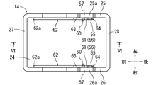
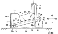
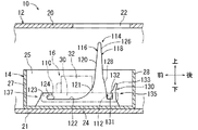
[実施形態1]実施形態1にかかる燃料タンクは、自動車等の車両に搭載される内燃機関用の燃料を貯留する燃料タンクである。各図において、上下方向は、車両に搭載された状態での燃料タンクの重力方向いわゆる天地方向に対応する。また、説明の都合上、燃料タンクの前後方向及び左右方向については、図に矢印で示すように定めるが、燃料タンク及び燃料ポンプの配置方向を特定するものではない。図1は燃料タンクを示す側断面図である。図1に示すように、燃料タンク10は、タンク本体12とサブタンク14とポンプユニット16とフランジユニット18とを備えている。 [Embodiment 1] A fuel tank according to Embodiment 1 is a fuel tank for storing fuel for an internal combustion engine mounted on a vehicle such as an automobile. In each figure, the vertical direction corresponds to the gravitational direction of the fuel tank in a state of being mounted on the vehicle, the so-called vertical direction. Further, for convenience of explanation, the front-rear direction and the left-right direction of the fuel tank are determined as shown by arrows in the figure, but the arrangement direction of the fuel tank and the fuel pump is not specified. FIG. 1 is a side sectional view showing a fuel tank. As shown in FIG. 1, the fuel tank 10 includes a tank body 12, a sub tank 14, a pump unit 16, and a flange unit 18.

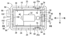
タンク本体12を説明する。タンク本体12は、上面部20及び底面部21を有する中空容器状に形成されている。上面部20には、円形孔からなるタンクホール22が形成されている。底面部21は、車両に対する燃料タンク10の搭載状態において水平状態に配置される。タンク本体12は、樹脂製でもよいし、金属製でもよい。なお、タンクホール22は本明細書でいう「開口部」に相当する。また、図2はサブタンクに対するポンプユニットの組付け状態を一部破断して示す側面図、図3は同じく平面図、図4は図3のIV−IV線矢視断面図である。   The tank body 12 will be described. The tank body 12 is formed in a hollow container shape having an upper surface portion 20 and a bottom surface portion 21. A tank hole 22 made of a circular hole is formed in the upper surface portion 20. The bottom surface portion 21 is arranged in a horizontal state when the fuel tank 10 is mounted on the vehicle. The tank body 12 may be made of resin or metal. The tank hole 22 corresponds to an “opening” in this specification. 2 is a partially cutaway side view showing the assembled state of the pump unit with respect to the sub tank, FIG. 3 is a plan view of the same, and FIG. 4 is a sectional view taken along line IV-IV in FIG.

次に、サブタンク14を説明する。図5はサブタンクを示す平面図、図6は図5のVI−VI線矢視断面図である。図5に示すように、サブタンク14は、平面視で前後方向を長くする長四角形状の容器状に形成されている。サブタンク14は、底板部24、左側板部25、右側板部26、前側板部27及び後側板部28を有している。底板部24は、水平方向に延在する平板状に形成されている。サブタンク14の上面は開放されている(図6参照)。図1に示すように、サブタンク14は、タンク本体12の底部すなわち底面部21上に固定状態に設置されている。底板部24は、底面部21と面接触状に配置されている。サブタンク14は、タンクホール22の下方又は下方付近に配置されている。サブタンク14は、燃料ポンプ32(後述する)に吸入される燃料を貯留する。サブタンク14は、樹脂製でもよいし、金属製でもよい。   Next, the sub tank 14 will be described. 5 is a plan view showing the sub-tank, and FIG. 6 is a sectional view taken along the line VI-VI in FIG. As shown in FIG. 5, the sub tank 14 is formed in a long rectangular container shape that is elongated in the front-rear direction in plan view. The sub tank 14 includes a bottom plate portion 24, a left side plate portion 25, a right side plate portion 26, a front side plate portion 27, and a rear side plate portion 28. The bottom plate portion 24 is formed in a flat plate shape extending in the horizontal direction. The upper surface of the sub tank 14 is open (see FIG. 6). As shown in FIG. 1, the sub tank 14 is installed in a fixed state on the bottom portion of the tank body 12, that is, the bottom surface portion 21. The bottom plate part 24 is arranged in surface contact with the bottom part 21. The sub tank 14 is disposed below or near the bottom of the tank hole 22. The sub tank 14 stores the fuel sucked into the fuel pump 32 (described later). The sub tank 14 may be made of resin or metal.

図6に示すように、サブタンク14の前端部における高さは、残りの部分における高さよりも高く設定されている。これにより、タンク本体12が前下がり状に傾いたときのサブタンク14の燃料貯留量が増大されている。また、サブタンク14の前端部を除いた残りの部分における左側板部25、右側板部26及び後側板部28の上端面は、同一高さで形成されている。このため、サブタンク14の水平状態での燃料を貯留可能な高さ位置Lは、サブタンク14の前端部を除いた残りの部分における左側板部25、右側板部26及び後側板部28の上端面の高さ位置となる。   As shown in FIG. 6, the height of the front end portion of the sub tank 14 is set higher than the height of the remaining portion. As a result, the amount of fuel stored in the sub tank 14 when the tank body 12 is tilted downward is increased. Moreover, the upper end surfaces of the left side plate portion 25, the right side plate portion 26, and the rear side plate portion 28 in the remaining portion excluding the front end portion of the sub tank 14 are formed at the same height. For this reason, the height position L at which the fuel in the horizontal state of the sub tank 14 can be stored is the upper end surface of the left side plate portion 25, the right side plate portion 26 and the rear side plate portion 28 in the remaining portion excluding the front end portion of the sub tank 14. It becomes the height position.

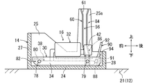
次に、ポンプユニット16を説明する。図4に示すように、ポンプユニット16は、マウント30及び燃料ポンプ32等を備えている。マウント30は、例えば樹脂製で、左右一対の支持側板34及び1枚の台板36を有している(図3参照)。両支持側板34は、左右方向に延在する帯板状に形成され、その板厚方向を左右方向に向けた状態で平行状に配置されている。台板36は、四角形板状に形成され、両支持側板34の上端面の中央部の相互間に水平状に架設されている。   Next, the pump unit 16 will be described. As shown in FIG. 4, the pump unit 16 includes a mount 30 and a fuel pump 32. The mount 30 is made of, for example, resin and includes a pair of left and right support side plates 34 and a single base plate 36 (see FIG. 3). Both supporting side plates 34 are formed in a strip shape extending in the left-right direction, and are arranged in parallel with the plate thickness direction directed in the left-right direction. The base plate 36 is formed in a quadrangular plate shape, and is laid horizontally between the center portions of the upper end surfaces of the support side plates 34.

マウント30は、水平又は略水平状態でサブタンク14内に収容されている。左側の支持側板34は左側板部25に対面され、右側の支持側板34は右側板部26に対面されている。両支持側板34の前端部は、前側板部27に近接又は当接されている。両支持側板34の前端下部には、R形状の円弧状面34aが形成されている。両支持側板34の後端下部には、傾斜状面34bが形成されている。なお、マウント30は本明細書でいう「ポンプ保持部材」に相当する。   The mount 30 is accommodated in the sub tank 14 in a horizontal or substantially horizontal state. The left support side plate 34 faces the left side plate portion 25, and the right support side plate 34 faces the right side plate portion 26. The front end portions of both support side plates 34 are close to or in contact with the front side plate portion 27. An R-shaped arcuate surface 34 a is formed at the lower part of the front end of both support side plates 34. An inclined surface 34 b is formed at the lower end of the rear end of both support side plates 34. The mount 30 corresponds to a “pump holding member” in this specification.

燃料ポンプ32は、サブタンク14内の燃料を吸入しかつ吐出する電動式の燃料ポンプである。燃料ポンプ32の外形は、略円柱形状に形成されている。燃料ポンプ32は、マウント30の台板36上に軸方向を水平方向すなわち前後方向とする横置き状態で配置されている。なお、燃料ポンプ32の軸方向の一端部に設けられた燃料吸入口(不図示)は前方に指向され、その他端部に設けられた燃料吐出口(不図示)は後方へ指向されている。また、燃料ポンプ32の横置き状態とはタンク本体12のタンクホール22に対して略平行をなす状態をいう。   The fuel pump 32 is an electric fuel pump that sucks and discharges fuel in the sub tank 14. The outer shape of the fuel pump 32 is formed in a substantially cylindrical shape. The fuel pump 32 is disposed on the base plate 36 of the mount 30 in a horizontal state in which the axial direction is the horizontal direction, that is, the front-rear direction. Note that a fuel inlet (not shown) provided at one end of the fuel pump 32 in the axial direction is directed forward, and a fuel outlet (not shown) provided at the other end is directed rearward. Further, the horizontally placed state of the fuel pump 32 refers to a state that is substantially parallel to the tank hole 22 of the tank body 12.

燃料ポンプ32(詳しくは燃料吸入口)には、燃料吸入用の燃料フィルタ38が接続されている。燃料フィルタ38は、フィルタ部材39と接続管40とを備えている。フィルタ部材39は、燃料ポンプ32に吸入される燃料すなわちサブタンク14内の燃料を濾過する。フィルタ部材39は、樹脂製の不織布等によって袋状に形成されている。フィルタ部材39の外形は、平面視(図3参照)で前後方向を長くする長四角形状で、上下方向に偏平に形成されている。また、フィルタ部材39の内部空間には、フィルタ部材39の袋形状を保持する樹脂製の内部保持部材(不図示)が配置されている。   A fuel filter 38 for fuel suction is connected to the fuel pump 32 (specifically, a fuel suction port). The fuel filter 38 includes a filter member 39 and a connection pipe 40. The filter member 39 filters the fuel sucked into the fuel pump 32, that is, the fuel in the sub tank 14. The filter member 39 is formed in a bag shape from a resin nonwoven fabric or the like. The outer shape of the filter member 39 is a long rectangular shape that lengthens the front-rear direction in plan view (see FIG. 3), and is formed flat in the vertical direction. A resin internal holding member (not shown) that holds the bag shape of the filter member 39 is disposed in the internal space of the filter member 39.

接続管40は、フィルタ部材39の前端部上に配置されている。接続管40は、樹脂製で、エルボ状に形成されている。接続管40の一端部は、内部保持部材(不図示)に接続されかつフィルタ部材39の内部空間に連通されている。接続管40の他端部は、燃料ポンプ32(詳しくは燃料吸入口)に接続されている。接続管40により、フィルタ部材39の内部空間と燃料ポンプ32の燃料吸入口とが連通されている。フィルタ部材39は、マウント30の両支持側板34と台板36とにより取り囲まれる空間内に水平状に収まるように配置されている。   The connecting pipe 40 is disposed on the front end portion of the filter member 39. The connecting tube 40 is made of resin and is formed in an elbow shape. One end of the connection pipe 40 is connected to an internal holding member (not shown) and communicated with the internal space of the filter member 39. The other end of the connection pipe 40 is connected to a fuel pump 32 (specifically, a fuel inlet). The connecting pipe 40 communicates the internal space of the filter member 39 with the fuel suction port of the fuel pump 32. The filter member 39 is disposed so as to fit horizontally in a space surrounded by both the support side plates 34 and the base plate 36 of the mount 30.

燃料ポンプ32(詳しくは燃料吐出口)には、プレッシャレギュレータ42が接続されている。プレッシャレギュレータ42は、燃料ポンプ32から吐出された燃料の圧力を調整し、その調整した燃料を吐出口(不図示)から吐出し、また、余剰となった余剰燃料を排出口(不図示)からタンク本体12内に排出する。   A pressure regulator 42 is connected to the fuel pump 32 (specifically, a fuel discharge port). The pressure regulator 42 adjusts the pressure of the fuel discharged from the fuel pump 32, discharges the adjusted fuel from a discharge port (not shown), and discharges excess surplus fuel from a discharge port (not shown). Discharge into the tank body 12.

ポンプユニット16は、前後方向を長手方向としてサブタンク14に組付けられることにより、タンク本体12内の底部に水平状態で配置されている(図1参照)。この状態では、サブタンク14の底板部24上にマウント30の両支持側板34の下端面が接触されている(図2参照)。底板部24と燃料フィルタ38のフィルタ部材39との間には、所定の隙間が確保されている(図4参照)。ポンプユニット16の長手方向の全長すなわち両支持側板34の全長は、タンク本体12のタンクホール22の口径よりも大きく設定されている。ポンプユニット16は、長手方向に沿ってタンクホール22を通過可能に形成されている。なお、タンクホール22を通過するポンプユニット16の姿勢は、タンクホール22に対してポンプユニット16の長手方向を垂直方向又は略垂直方向に向けた姿勢に相当するため、垂直姿勢又は略垂直姿勢という(図7及び図8参照)。また、本明細書でいう「略垂直姿勢」には、ポンプユニット16がタンクホール22に対して傾斜する傾斜姿勢(例えば、傾斜角45°以下)も含まれる。また、サブタンク14に対するポンプユニット16の組付け位置は、ポンプユニット16の長手方向を水平方向又は略水平方向に向けた姿勢に相当する(図2〜図4参照)。また、本実施形態では、ポンプユニット16の長手方向は、燃料ポンプ32の軸方向に相当する。また、ポンプユニット16の長手方向に対して燃料ポンプ32の軸方向が上下方向及び/又は水平方向に傾斜していてもよい。なお、サブタンク14に対するポンプユニット16の組付け構造については後で説明する。   The pump unit 16 is arranged in a horizontal state at the bottom in the tank body 12 by being assembled to the sub tank 14 with the front-rear direction as the longitudinal direction (see FIG. 1). In this state, the lower end surfaces of both support side plates 34 of the mount 30 are in contact with the bottom plate portion 24 of the sub tank 14 (see FIG. 2). A predetermined gap is secured between the bottom plate portion 24 and the filter member 39 of the fuel filter 38 (see FIG. 4). The total length of the pump unit 16 in the longitudinal direction, that is, the total length of both support side plates 34 is set to be larger than the diameter of the tank hole 22 of the tank body 12. The pump unit 16 is formed so as to be able to pass through the tank hole 22 along the longitudinal direction. Note that the posture of the pump unit 16 that passes through the tank hole 22 corresponds to a posture in which the longitudinal direction of the pump unit 16 is directed to the vertical direction or the substantially vertical direction with respect to the tank hole 22, and is therefore referred to as a vertical posture or a substantially vertical posture. (See FIGS. 7 and 8). In addition, the “substantially vertical posture” in this specification includes an inclined posture in which the pump unit 16 is inclined with respect to the tank hole 22 (for example, an inclination angle of 45 ° or less). Further, the assembly position of the pump unit 16 with respect to the sub tank 14 corresponds to a posture in which the longitudinal direction of the pump unit 16 is directed in the horizontal direction or the substantially horizontal direction (see FIGS. 2 to 4). In the present embodiment, the longitudinal direction of the pump unit 16 corresponds to the axial direction of the fuel pump 32. Further, the axial direction of the fuel pump 32 may be inclined in the vertical direction and / or the horizontal direction with respect to the longitudinal direction of the pump unit 16. The assembly structure of the pump unit 16 to the sub tank 14 will be described later.

次に、フランジユニット18を説明する。図1に示すように、フランジユニット18は、タンク本体12のタンクホール22に装着されている。フランジユニット18は、例えば樹脂製で、タンクホール22を閉鎖する円板状のフランジ本体44を備えている。フランジ本体44には、燃料吐出管45及び電気コネクタ46等が設けられている。フランジ本体44の下面側において、燃料吐出管45とプレッシャレギュレータ42(詳しくは吐出口)とは、可撓性を有する蛇腹状のホース等からなる配管部材48を介して接続されている。また、フランジ本体44の下面側において、フランジ本体44の電気コネクタ46と燃料ポンプ32(詳しくは電気コネクタ(不図示))とは、可撓性を有する配線部材49を介して接続されている。また、図示しないが、フランジ本体44の上面側において、燃料吐出管45には、内燃機関いわゆるエンジンにつながる燃料供給配管が接続される。また、電気コネクタ46には、外部コネクタが接続される。   Next, the flange unit 18 will be described. As shown in FIG. 1, the flange unit 18 is mounted in the tank hole 22 of the tank body 12. The flange unit 18 is made of, for example, resin and includes a disk-shaped flange main body 44 that closes the tank hole 22. The flange main body 44 is provided with a fuel discharge pipe 45, an electrical connector 46, and the like. On the lower surface side of the flange main body 44, the fuel discharge pipe 45 and the pressure regulator 42 (specifically, the discharge port) are connected via a piping member 48 made of a flexible bellows-like hose or the like. In addition, on the lower surface side of the flange body 44, the electrical connector 46 of the flange body 44 and the fuel pump 32 (specifically, an electrical connector (not shown)) are connected via a flexible wiring member 49. Although not shown, on the upper surface side of the flange main body 44, the fuel discharge pipe 45 is connected to a fuel supply pipe connected to the internal combustion engine, so-called engine. In addition, an external connector is connected to the electrical connector 46.

次に、ポンプユニット16の作動を説明する。外部からの駆動電力により燃料ポンプ32が駆動されると、サブタンク14内の燃料が、燃料フィルタ38を介して燃料ポンプ32に吸入される。その燃料は、燃料ポンプ32により昇圧された後、プレッシャレギュレータ42により燃料圧力が調整されてから配管部材48へ吐出される。その燃料は、フランジユニット18の燃料吐出管45からエンジンへと供給される。なお、ポンプユニット16とフランジユニット18とにより、タンク本体12内に貯留された燃料をエンジンに供給する燃料供給装置が構成されている。   Next, the operation of the pump unit 16 will be described. When the fuel pump 32 is driven by driving power from the outside, the fuel in the sub tank 14 is sucked into the fuel pump 32 via the fuel filter 38. The fuel is boosted by the fuel pump 32 and then discharged to the piping member 48 after the fuel pressure is adjusted by the pressure regulator 42. The fuel is supplied from the fuel discharge pipe 45 of the flange unit 18 to the engine. The pump unit 16 and the flange unit 18 constitute a fuel supply device that supplies the fuel stored in the tank body 12 to the engine.

次に、サブタンク14に対するポンプユニット16の組付け構造について説明する。図2及び図3に示すように、マウント30の両支持側板34の前端部には、それぞれ外側方へ向けて突出する丸軸形状の前側のガイドピン51が左右対称的に設けられている。両支持側板34の後端部には、それぞれ外側方へ向けて突出する丸軸形状の後側のガイドピン53が左右対称的に設けられている。なお、前側のガイドピン51は本明細書でいう「摺動子」、「先行側摺動子」に相当する。また、後側のガイドピン53は本明細書でいう「摺動子」、「後行側摺動子」に相当する。なお、ガイドピン51,53は、丸軸形状に限らず、四角軸状、帯板状等でもよい。   Next, an assembly structure of the pump unit 16 with respect to the sub tank 14 will be described. As shown in FIGS. 2 and 3, round shaft-shaped front guide pins 51 that protrude outward are respectively provided symmetrically at the front end portions of the two support side plates 34 of the mount 30. At the rear end portions of both supporting side plates 34, rear shaft-side guide pins 53 projecting outward are provided symmetrically. The front guide pin 51 corresponds to “slider” and “preceding side slider” in this specification. The rear guide pin 53 corresponds to a “slider” and a “rear slider” in the present specification. The guide pins 51 and 53 are not limited to a round shaft shape, and may be a square shaft shape, a band plate shape, or the like.

図5に示すように、サブタンク14の左側板部25及び右側板部26の対向側面すなわち内側面には、左右一対のガイドレール55が左右対称的に設けられている。両ガイドレール55は、ガイド溝56を有する断面チャンネル状に形成されている。ガイド溝56は、マウント30の両ガイドピン51,53(図2参照)を係合可能かつ摺動可能に形成されている。   As shown in FIG. 5, a pair of left and right guide rails 55 are provided symmetrically on opposite side surfaces, that is, inner side surfaces of the left side plate portion 25 and the right side plate portion 26 of the sub tank 14. Both guide rails 55 are formed in a cross-sectional channel shape having guide grooves 56. The guide groove 56 is formed so that both guide pins 51 and 53 (see FIG. 2) of the mount 30 can be engaged and slidable.

図6に示すように、ガイドレール55は、1つの溝底壁57と、相互に平行状をなす一対の溝側壁58とを有している。両ガイドレール55は、左側板部25及び右側板部26の一部を溝底壁57として兼用している。なお、溝底壁57を有するガイドレール55を左側板部25及び右側板部26に付設してもよい。   As shown in FIG. 6, the guide rail 55 has one groove bottom wall 57 and a pair of groove side walls 58 that are parallel to each other. Both the guide rails 55 also serve as a groove bottom wall 57 with a part of the left side plate portion 25 and the right side plate portion 26. A guide rail 55 having a groove bottom wall 57 may be attached to the left side plate portion 25 and the right side plate portion 26.

ガイドレール55は、第1ガイド部60と第3ガイド部62と第2ガイド部64を有している。第1ガイド部60は、タンク本体12のタンクホール22側から底部側に延在している。すなわち、第1ガイド部60は、垂直方向又は略垂直方向に延在している。第1ガイド部60は、サブタンク14の水平状態での燃料を貯留可能な高さ位置Lよりも上方へ延出されている。これにともない、サブタンク14の左側板部25及び右側板部26には、上方へ突出する突出部25a,26a(図5参照)が形成されている。また、第1ガイド部60のガイド溝56の上端部には、上方に開口する導入口61が形成されている。導入口61における一対の溝側壁58は、相互間の間隔を上方に向かって次第に広くするテーパー状に形成されている。導入口61は、タンク本体12のタンクホール22の近傍に配置されており、作業者が容易に視認することができる(図1参照)。   The guide rail 55 has a first guide part 60, a third guide part 62, and a second guide part 64. The first guide part 60 extends from the tank hole 22 side of the tank body 12 to the bottom side. That is, the first guide portion 60 extends in the vertical direction or the substantially vertical direction. The first guide portion 60 extends upward from a height position L where the fuel in the horizontal state of the sub tank 14 can be stored. Accordingly, the left side plate portion 25 and the right side plate portion 26 of the sub tank 14 are formed with protruding portions 25a and 26a (see FIG. 5) protruding upward. In addition, an inlet 61 that opens upward is formed at the upper end of the guide groove 56 of the first guide portion 60. The pair of groove sidewalls 58 in the introduction port 61 are formed in a tapered shape that gradually increases the distance between them upward. The introduction port 61 is disposed in the vicinity of the tank hole 22 of the tank body 12 and can be easily visually recognized by an operator (see FIG. 1).

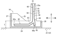
図6に示すように、第3ガイド部62は、第1ガイド部60の底部側端部すなわち下端部に連続されかつ前方へ延出されている。第3ガイド部62の後端部は、前方斜め下方に傾斜する傾斜部63となっている。第3ガイド部62のガイド溝56の前端面は、前端壁62aによって閉鎖されている。また、サブタンク14に対するポンプユニット16の組付けに際して、第3ガイド部62の前端壁62aにマウント30の前側のガイドピン51が当接したときには、後側のガイドピン53が第1ガイド部60の下端部付近すなわち第2ガイド部64の接続部付近に位置される(図9参照)。   As shown in FIG. 6, the third guide portion 62 is continuous with the bottom side end portion, that is, the lower end portion of the first guide portion 60, and extends forward. The rear end portion of the third guide portion 62 is an inclined portion 63 that is inclined obliquely downward and forward. A front end surface of the guide groove 56 of the third guide portion 62 is closed by a front end wall 62a. Further, when the pump unit 16 is assembled to the sub tank 14, when the front guide pin 51 of the mount 30 comes into contact with the front end wall 62 a of the third guide portion 62, the rear guide pin 53 is attached to the first guide portion 60. It is located near the lower end, that is, near the connecting portion of the second guide portion 64 (see FIG. 9).

第2ガイド部64は、第1ガイド部60の下端部に連続されかつ下方へ円弧状に延出されている。第2ガイド部64のガイド溝56の下端部は、下端壁64aによって閉鎖されている。また、第2ガイド部64は、第3ガイド部62の前端壁62aに当接した状態での前側のガイドピン51を中心とするマウント30の上下方向の回動にともなう後側のガイドピン53の回動軌跡に略倣う曲率半径で形成されている。   The second guide portion 64 is continuous with the lower end portion of the first guide portion 60 and extends downward in an arc shape. A lower end portion of the guide groove 56 of the second guide portion 64 is closed by a lower end wall 64a. In addition, the second guide portion 64 has a rear guide pin 53 that accompanies the vertical rotation of the mount 30 around the front guide pin 51 in a state of being in contact with the front end wall 62a of the third guide portion 62. Is formed with a radius of curvature that substantially follows the rotation trajectory.

ところで、本実施形態において、第2ガイド部64(図6参照)の曲率半径は、下方に向かって次第に小さくなるように設定されている。第2ガイド部64の後側の溝側壁58の下端部には、後方へ円弧状に凹むロック溝部65が形成されている。また、マウント30(図2参照)は、前後方向の中央部が盛り上がる上反り状態に弾性変形いわゆる撓み変形可能に形成されている。なお、マウント30は、前後方向の中央部が凹む下反り状態に弾性変形いわゆる撓み変形可能に形成されてもよい。   By the way, in this embodiment, the curvature radius of the 2nd guide part 64 (refer FIG. 6) is set so that it may become small gradually toward the downward direction. At the lower end of the groove side wall 58 on the rear side of the second guide portion 64, a lock groove portion 65 that is recessed backward in an arc shape is formed. In addition, the mount 30 (see FIG. 2) is formed so as to be elastically deformed, that is, so-called flexibly deformed, in a warped state in which the central portion in the front-rear direction is raised. The mount 30 may be formed so as to be elastically deformed, that is, so-called flexibly deformed, in a downward warped state in which a central portion in the front-rear direction is recessed.

このため、ポンプユニット16を傾斜姿勢(図9参照)からサブタンク14に対する組付け位置(図2参照)へ回動させたときには、後側のガイドピン53が第2ガイド部64を摺動しつつ前方へ押しやられる。これによって、マウント30が上反り状態に弾性変形させられる。そして、ポンプユニット16がサブタンク14に対する組付け位置(図2参照)になると、後側のガイドピン53が第2ガイド部64の下端壁64aに当接し、後側のガイドピン53がマウント30の弾性復元力によってロック溝部65に係合いわゆるスナップフィット係合される。これにより、タンク本体12にポンプユニット16がロックされる。すなわち、第2ガイド部64のロック溝部65と後側のガイドピン53とにより、ロック手段67が構成されている。なお、サブタンク14に対する組付け位置は本明細書でいう「タンク本体の底部側の組付け位置」に相当する。   Therefore, when the pump unit 16 is rotated from the inclined posture (see FIG. 9) to the assembly position (see FIG. 2) with respect to the sub tank 14, the rear guide pin 53 slides on the second guide portion 64. Pushed forward. As a result, the mount 30 is elastically deformed into a warped state. When the pump unit 16 is in the assembly position with respect to the sub tank 14 (see FIG. 2), the rear guide pin 53 comes into contact with the lower end wall 64a of the second guide portion 64, and the rear guide pin 53 is attached to the mount 30. The lock groove 65 is engaged by the elastic restoring force, so-called snap-fit engagement. As a result, the pump unit 16 is locked to the tank body 12. That is, the lock means 67 is configured by the lock groove portion 65 of the second guide portion 64 and the rear guide pin 53. The assembly position with respect to the sub tank 14 corresponds to the “assembly position on the bottom side of the tank body” in this specification.

また、マウント30は本明細書でいう「摺動子側の部材」に相当する。また、ロック溝部65は本明細書でいう「ロック部」、「タンク本体側ロック部」に相当する。また、両ガイドピン51,53とガイドレール55とにより、ガイド手段が構成されている。ガイド手段は、ポンプユニット16の左右両側に対称的に配置されている(図3参照)。また、第3ガイド部62の前端部に相当する前端壁62aを本明細書でいう「タンク本体側支持部」とし、前側のガイドピン51を本明細書でいう「ポンプユニット側支持部」として、相互に回動可能にかつ係脱可能に係合する回動支持手段72が構成されている(図2参照)。   The mount 30 corresponds to a “slider side member” in this specification. Further, the lock groove portion 65 corresponds to a “lock portion” and a “tank body side lock portion” in this specification. The guide pins 51 and 53 and the guide rail 55 constitute guide means. The guide means are symmetrically disposed on the left and right sides of the pump unit 16 (see FIG. 3). Further, the front end wall 62a corresponding to the front end portion of the third guide portion 62 is referred to as a “tank body side support portion” in the present specification, and the front guide pin 51 is referred to as a “pump unit side support portion” in the specification. Rotating support means 72 are configured to engage with each other so as to be rotatable and detachable (see FIG. 2).

次に、タンク本体12に対するポンプユニット16の組付け方法について説明する。ポンプユニット16の組付けは、作業者の手作業で行われる。タンク本体12の上方からタンクホール22(図1参照)内にポンプユニット16を長手方向に沿って挿入する。このとき、ポンプユニット16は、前端部を下向きとする垂直姿勢又は略垂直姿勢とされる。なお、垂直姿勢又は略垂直姿勢には、ポンプユニット16の前端部を下方斜め前方に傾斜する傾斜姿勢も含まれる。   Next, a method for assembling the pump unit 16 to the tank body 12 will be described. The assembly of the pump unit 16 is performed manually by the operator. The pump unit 16 is inserted from above the tank body 12 into the tank hole 22 (see FIG. 1) along the longitudinal direction. At this time, the pump unit 16 is in a vertical posture or a substantially vertical posture with the front end portion facing downward. The vertical posture or the substantially vertical posture includes a tilted posture in which the front end portion of the pump unit 16 is tilted downward and forward.

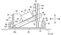
そして、ポンプユニット16の前側のガイドピン51を、サブタンク14のガイドレール55の導入口61から第1ガイド部60に係合させ、そのガイド部60に沿って下方へ摺動させていく。続いて、前側のガイドピン51を、第1ガイド部60の下端部から第3ガイド部62に摺動させる。また、後側のガイドピン53を、ガイドレール55の導入口61から第1ガイド部60に係合させる。この状態が図7及び図8に示されている。なお、図7はタンク本体に対するポンプユニットの組付け過程1を示す側断面図、図8は図7のVIII−VIII線矢視断面図である。   Then, the guide pin 51 on the front side of the pump unit 16 is engaged with the first guide portion 60 from the introduction port 61 of the guide rail 55 of the sub tank 14 and is slid downward along the guide portion 60. Subsequently, the front guide pin 51 is slid from the lower end portion of the first guide portion 60 to the third guide portion 62. Further, the rear guide pin 53 is engaged with the first guide portion 60 from the inlet 61 of the guide rail 55. This state is shown in FIGS. 7 is a side sectional view showing the assembly process 1 of the pump unit to the tank body, and FIG. 8 is a sectional view taken along the line VIII-VIII in FIG.

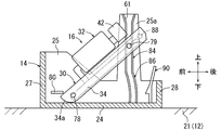
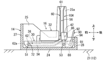
この状態から、前側のガイドピン51を、第3ガイド部62に沿って前方へ移動させつつ、後側のガイドピン53を第1ガイド部60に沿って下方へ摺動させていく。すると、前側のガイドピン51が第3ガイド部62の前端壁62aに当接すなわち係合する。これにより、ポンプユニット16が後端部を斜め上方に傾斜する傾斜姿勢とされる。この状態が図9に示されている。図9はタンク本体に対するポンプユニットの組付け過程2を示す側断面図である。   From this state, the front guide pin 51 is moved forward along the third guide portion 62, and the rear guide pin 53 is slid downward along the first guide portion 60. Then, the front guide pin 51 comes into contact with, or engages with, the front end wall 62 a of the third guide portion 62. As a result, the pump unit 16 has an inclined posture in which the rear end portion is inclined obliquely upward. This state is shown in FIG. FIG. 9 is a side sectional view showing a process 2 for assembling the pump unit to the tank body.

続いて、第3ガイド部62の前端壁62aと前側のガイドピン51との係合による回動支持手段72(図9参照)を回動支点として、ポンプユニット16を下方へ回動させる。すなわち、ポンプユニット16の後端部を押し下げていく。すると、後側のガイドピン53が第2ガイド部64を摺動しつつ前方へ押しやられることによって、マウント30が弾性変形させられる。そして、ポンプユニット16がサブタンク14に対する組付け位置(図2参照)になると、後側のガイドピン53が第2ガイド部64の下端壁64aに当接し、後側のガイドピン53がマウント30の弾性復元力によってロック溝部65に係合される。これにより、タンク本体12にポンプユニット16がロックされる。この状態では、マウント30の両支持側板34の下端面がサブタンク14の底板部24上に当接する。その後、フランジユニット18をタンク本体12のタンクホール22に装着することによって、ポンプユニット16の組付け作業が完了する(図1参照)。   Subsequently, the pump unit 16 is rotated downward with the rotation support means 72 (see FIG. 9) by the engagement between the front end wall 62a of the third guide portion 62 and the front guide pin 51 as a rotation fulcrum. That is, the rear end portion of the pump unit 16 is pushed down. Then, the mount 30 is elastically deformed by pushing the rear guide pin 53 forward while sliding the second guide portion 64. When the pump unit 16 is in the assembly position with respect to the sub tank 14 (see FIG. 2), the rear guide pin 53 comes into contact with the lower end wall 64a of the second guide portion 64, and the rear guide pin 53 is attached to the mount 30. The lock groove 65 is engaged with the elastic restoring force. As a result, the pump unit 16 is locked to the tank body 12. In this state, the lower end surfaces of both support side plates 34 of the mount 30 abut on the bottom plate portion 24 of the sub tank 14. Thereafter, the assembly of the pump unit 16 is completed by mounting the flange unit 18 in the tank hole 22 of the tank body 12 (see FIG. 1).

また、燃料フィルタ38の目詰まり、燃料ポンプ32の故障等を生じた場合のポンプユニット16の交換等に際して、ポンプユニット16を取外したい場合がある。そのような場合には、タンク本体12のタンクホール22からフランジユニット18を取外した後、回動支持手段72(図2参照)を回動支点として、ポンプユニット16を上方へ回動させる。すなわち、ポンプユニット16の後端部を引き上げる。これにより、ガイドレール55のロック溝部65に対する後側のガイドピン53の係合が解除される。以降、挿入時とは逆順で、ポンプユニット16を取外せばよい。   In some cases, the pump unit 16 may be removed when replacing the pump unit 16 when the fuel filter 38 is clogged, the fuel pump 32 is broken, or the like. In such a case, after removing the flange unit 18 from the tank hole 22 of the tank body 12, the pump unit 16 is rotated upward with the rotation support means 72 (see FIG. 2) as a rotation fulcrum. That is, the rear end portion of the pump unit 16 is pulled up. Thereby, the engagement of the rear guide pin 53 with respect to the lock groove portion 65 of the guide rail 55 is released. Thereafter, the pump unit 16 may be removed in the reverse order of insertion.

前記した燃料タンク10によると、タンク本体12内にポンプユニット16を組付ける際に、ガイド手段のガイドレール55によって両ガイドピン51,53がガイドされる。これによって、ポンプユニット16がタンク本体12のタンクホール22側から底部側の組付け位置までガイドされる。したがって、ポンプユニット16を迷わずに容易に組付け位置へ適正に移動させることができる。このため、作業時間を短縮するとともに、ポンプユニット16の組付け不良を抑制することができる。よって、タンク本体12に対するポンプユニット16の組付け性を向上することができる。   According to the fuel tank 10 described above, when the pump unit 16 is assembled in the tank main body 12, the guide pins 51 and 53 are guided by the guide rail 55 of the guide means. As a result, the pump unit 16 is guided from the tank hole 22 side of the tank body 12 to the assembly position on the bottom side. Therefore, the pump unit 16 can be easily moved appropriately to the assembly position without hesitation. For this reason, while shortening working time, the assembly | attachment defect of the pump unit 16 can be suppressed. Therefore, the assembling property of the pump unit 16 to the tank body 12 can be improved.

また、ガイド手段は、ポンプユニット16の両側に配置されている(図3及び図8参照)。したがって、ポンプユニット16が両ガイド手段によってガイドされるため、タンク本体12に対するポンプユニット16の組付け性を向上することができる。   Moreover, the guide means is arrange | positioned at the both sides of the pump unit 16 (refer FIG.3 and FIG.8). Therefore, since the pump unit 16 is guided by both guide means, the assembling property of the pump unit 16 with respect to the tank body 12 can be improved.

また、ガイドレール55は、タンク本体12の底部に設けられたサブタンク14の水平状態での燃料を貯留可能な高さ位置Lよりも上方へ延出されている(図6参照)。したがって、位置Lよりも高い位置からガイドレール55によって両ガイドピン51,53をガイドすることができる。また、作業者は、タンク本体12のタンクホール22近傍のガイドレール55の導入口61を目視で確認しながら、その導入口61にポンプユニット16の両ガイドピン51,53を容易に係合させることができる。よって、ポンプユニット16の組付けにかかる信頼性を向上することができる。また、ポンプユニット16の組付け時のタンクホール22に対するポンプユニット16の干渉を抑制することができる。このため、タンクホール22とポンプユニット16との干渉によるポンプユニット16の損傷、バリ、切り粉等の異物の発生及びタンク本体12内への脱落を抑制することができる。   Moreover, the guide rail 55 is extended upwards from the height position L which can store the fuel in the horizontal state of the sub tank 14 provided in the bottom part of the tank main body 12 (refer FIG. 6). Therefore, both guide pins 51 and 53 can be guided by the guide rail 55 from a position higher than the position L. Further, the operator can easily engage the guide pins 51 and 53 of the pump unit 16 with the introduction port 61 while visually confirming the introduction port 61 of the guide rail 55 near the tank hole 22 of the tank body 12. be able to. Therefore, the reliability concerning the assembly of the pump unit 16 can be improved. Further, interference of the pump unit 16 with the tank hole 22 when the pump unit 16 is assembled can be suppressed. For this reason, it is possible to suppress damage to the pump unit 16 due to interference between the tank hole 22 and the pump unit 16, generation of foreign matters such as burrs and chips, and dropping into the tank body 12.

また、ポンプユニット16の長手方向の一端部を回動可能に支持する回動支持手段72が、タンク本体12側に設けられた第3ガイド部62の前端壁62a(タンク本体側支持部)と、ポンプユニット16側に設けられかつ第3ガイド部62の前端壁62aに係合される前側のガイドピン51(ポンプユニット側支持部)とにより構成されている。また、ガイドレール55には、タンク本体12のタンクホール22側から底部側に延在する第1ガイド部60が設けられている。したがって、ガイドレール55の第1ガイド部60により、ポンプユニット16の前側のガイドピン51をタンク本体12のタンクホール22側から底部側にガイドすることができる。また、ポンプユニット16を傾斜姿勢(図9参照)からサブタンク14に対する組付け位置(図2参照)とする際には、回動支持手段72の第3ガイド部62の前端壁62a(タンク本体側支持部)と前側のガイドピン51(ポンプユニット側支持部)との係合により、ポンプユニット16の長手方向の一端部(前端部)を回動可能に支持することができる(図2及び図9参照)。よって、回動支持手段72を回動支点として、ポンプユニット16をタンク本体12の底部側の組付け位置に容易に回動させることができる。   Further, a rotation support means 72 that rotatably supports one end portion of the pump unit 16 in the longitudinal direction is provided with a front end wall 62a (tank body side support portion) of the third guide portion 62 provided on the tank body 12 side. The front guide pin 51 (pump unit side support part) is provided on the pump unit 16 side and engaged with the front end wall 62a of the third guide part 62. Further, the guide rail 55 is provided with a first guide portion 60 extending from the tank hole 22 side to the bottom side of the tank body 12. Therefore, the first guide portion 60 of the guide rail 55 can guide the guide pin 51 on the front side of the pump unit 16 from the tank hole 22 side to the bottom side of the tank body 12. Further, when the pump unit 16 is moved from the inclined posture (see FIG. 9) to the assembly position with respect to the sub tank 14 (see FIG. 2), the front end wall 62a (the tank body side) of the third guide portion 62 of the rotation support means 72 is used. One end portion (front end portion) in the longitudinal direction of the pump unit 16 can be rotatably supported by engagement between the support portion) and the front guide pin 51 (pump unit side support portion) (FIGS. 2 and FIG. 2). 9). Therefore, the pump unit 16 can be easily rotated to the assembly position on the bottom side of the tank body 12 with the rotation support means 72 as the rotation fulcrum.

また、第1ガイド部60の底部側端部に連続され、回動支持手段72を回動支点としてポンプユニット16を下方へ回動させる際に後側のガイドピン53をガイドする第2ガイド部64が設けられている。したがって、回動支持手段72を回動支点としてポンプユニット16を回動させることにより、後側のガイドピン53がガイドレール55の第2ガイド部64によりガイドされる。このため、ポンプユニット16をタンク本体12の底部側の組付け位置に容易に移動させることができる。   Also, a second guide portion that is continuous with the bottom side end portion of the first guide portion 60 and guides the rear guide pin 53 when the pump unit 16 is rotated downward with the rotation support means 72 as a rotation fulcrum. 64 is provided. Therefore, by rotating the pump unit 16 using the rotation support means 72 as a rotation fulcrum, the rear guide pin 53 is guided by the second guide portion 64 of the guide rail 55. For this reason, the pump unit 16 can be easily moved to the assembly position on the bottom side of the tank body 12.

また、後側のガイドピン53がガイドレール55の第2ガイド部64を下方に摺動した際に、マウント30が弾性変形する。そして、ポンプユニット16をサブタンク14に対する組付け位置(図2参照)としたときには、マウント30の弾性復元により、第2ガイド部64のロック溝部65に後側のガイドピン53が係合することによって、タンク本体12にポンプユニット16がロックされる。また、マウント30の弾性を利用して、第2ガイド部64のロック溝部65に対する後側のガイドピン53の係合を解除することによって、ポンプユニット16を挿入時とは逆順で取外すことができる。よって、ポンプユニット16をタンク本体12に着脱可能に組付けることができる。また、第2ガイド部64のロック溝部65と後側のガイドピン53とによりロック手段67(図2参照)が構成されるため、ロック手段67としての特別な部材(例えば、バネ部材等)を設けなくて済む。   Further, when the rear guide pin 53 slides downward on the second guide portion 64 of the guide rail 55, the mount 30 is elastically deformed. When the pump unit 16 is set to the sub tank 14 (see FIG. 2), the rear guide pin 53 is engaged with the lock groove portion 65 of the second guide portion 64 due to the elastic restoration of the mount 30. The pump unit 16 is locked to the tank body 12. Further, by using the elasticity of the mount 30 to release the engagement of the rear guide pin 53 with respect to the lock groove portion 65 of the second guide portion 64, the pump unit 16 can be removed in the reverse order of insertion. . Therefore, the pump unit 16 can be detachably assembled to the tank body 12. Further, since the lock groove 67 (see FIG. 2) is configured by the lock groove portion 65 of the second guide portion 64 and the rear guide pin 53, a special member (for example, a spring member or the like) as the lock means 67 is used. It is not necessary to provide it.

また、ポンプユニット16の長手方向の一端部に、前側のガイドピン51が設けられ、ガイドレール55には、第1ガイド部60の底部側端部に連続され、前側のガイドピン51をタンク本体12の底部に沿って所定位置までガイドする第3ガイド部62が設けられている。したがって、前側のガイドピン51を、ガイドレール55の第1ガイド部60及び第3ガイド部62によって、回動支持手段72に向けてガイドすることができる。   Further, a front guide pin 51 is provided at one end of the pump unit 16 in the longitudinal direction, and the guide rail 55 is connected to the bottom side end of the first guide portion 60 so that the front guide pin 51 is connected to the tank body. A third guide portion 62 is provided for guiding to a predetermined position along the bottom of 12. Therefore, the front guide pin 51 can be guided toward the rotation support means 72 by the first guide portion 60 and the third guide portion 62 of the guide rail 55.

また、前側のガイドピン51は、回動支持手段72(図2参照)のポンプユニット側支持部を兼用するように構成されている。したがって、ポンプユニット側支持部として、特別な部材を設けなくて済む。また、第3ガイド部62の前端壁62aを、回動支持手段72のタンク本体側支持部とすることによって、タンク本体側支持部として特別な部材を設けなくて済む。   Further, the front guide pin 51 is configured to also serve as a pump unit side support portion of the rotation support means 72 (see FIG. 2). Therefore, it is not necessary to provide a special member as the pump unit side support portion. Further, by using the front end wall 62a of the third guide portion 62 as the tank body side support portion of the rotation support means 72, it is not necessary to provide a special member as the tank body side support portion.

なお、弾性変形可能な摺動子側の部材としては、マウント30に限らず、前側のガイドピン51及び/又は後側のガイドピン53を用いてもよい。また、摺動子側の部材を弾性変形可能に形成する代わりに、マウント30に対して前側のガイドピン51及び/又は後側のガイドピン53を相互間の間隔を狭める方向にスライド可能に配置し、そのガイドピンをバネ部材によって相互間の間隔を拡げる方向に付勢する構成としてもよい。   The member on the slider side that can be elastically deformed is not limited to the mount 30, and a front guide pin 51 and / or a rear guide pin 53 may be used. Further, instead of forming the slider side member so as to be elastically deformable, the front guide pin 51 and / or the rear guide pin 53 are arranged to be slidable with respect to the mount 30 in the direction of narrowing the interval between them. And it is good also as a structure which urges | biases the guide pin in the direction which expands the space | interval between them with a spring member.

[実施形態2]実施形態2以降の実施形態は、実施形態1に変更を加えたものであるから、その変更部分について説明し、重複する説明は省略する。図10はサブタンクを示す平面図である。図10に示すように、サブタンク(符号、74を付す)は、実施形態1(図5参照)のサブタンク14の後側板部28が省略されている。サブタンク74は、実施形態1のサブタンク14の左右方向の幅寸法よりも広い幅寸法で形成されている。左右のガイドレール55は、左側板部25及び右側板部26とは別個に形成されている。すなわち、底板部24上には、左側板75及び右側板76が立設されている。左側板75と右側板76との間隔は、実施形態1のサブタンク14(図5参照)の左側板部25と右側板部26との間隔と同じに設定されている。左側板75及び右側板76の対向側面にガイドレール55が左右対称的に設けられている。ガイドレール55は、左側板75及び右側板76の一部を溝底壁57として兼用している。また、左側板部25及び右側板部26には、実施形態1(図5参照)の突出部25a,26aは形成されていない。 [Embodiment 2] Since the embodiment after the embodiment 2 is a modification of the embodiment 1, the changed portion will be described, and the overlapping description will be omitted. FIG. 10 is a plan view showing the sub tank. As shown in FIG. 10, the rear tank 28 of the sub tank 14 of the first embodiment (see FIG. 5) is omitted from the sub tank (reference numeral 74). The sub tank 74 is formed with a width that is wider than the width in the left-right direction of the sub tank 14 of the first embodiment. The left and right guide rails 55 are formed separately from the left side plate portion 25 and the right side plate portion 26. That is, the left side plate 75 and the right side plate 76 are erected on the bottom plate portion 24. The interval between the left side plate 75 and the right side plate 76 is set to be the same as the interval between the left side plate portion 25 and the right side plate portion 26 of the sub tank 14 (see FIG. 5) of the first embodiment. Guide rails 55 are provided symmetrically on opposite sides of the left side plate 75 and the right side plate 76. The guide rail 55 also serves as a groove bottom wall 57 with part of the left side plate 75 and the right side plate 76. Further, the left plate portion 25 and the right plate portion 26 are not formed with the protruding portions 25a and 26a of the first embodiment (see FIG. 5).

本実施形態のサブタンク74によると、実施形態1のポンプユニット16を共通使用することができる。なお、ガイドレール55を備える左側板75及び右側板76は、タンク本体12の底面部21上に配置してもよい。また、溝底壁57を有するガイドレール55をサブタンク14の底板部24又はタンク本体12の底面部21上に配置してもよい。   According to the sub tank 74 of the present embodiment, the pump unit 16 of the first embodiment can be commonly used. Note that the left side plate 75 and the right side plate 76 including the guide rail 55 may be disposed on the bottom surface portion 21 of the tank body 12. Further, the guide rail 55 having the groove bottom wall 57 may be disposed on the bottom plate portion 24 of the sub tank 14 or the bottom surface portion 21 of the tank body 12.

[実施形態3]図11はサブタンクに対するポンプユニットの組付け状態を一部破断して示す側面図、図12はサブタンクを示す平面図、図13は図12のXIII−XIII線矢視断面図である。図11に示すように、本実施形態では、実施形態1(図2参照)における前側のガイドピン51は、ストッパピン(符号、78を付す)として用いられる。また、実施形態1における後側のガイドピン53は、ガイドピン(符号、79を付す)として用いられる。図12及び図13に示すように、サブタンク14の左側板部25及び右側板部26の前端部の内側面には、左右一対のストッパ片80が左右対称的に設けられている。ストッパ片80は、前後方向に延びる突片状に形成されている。なお、ストッパピン78は本明細書でいう「ストッパ部材」に相当する。また、ガイドピン79は本明細書でいう「摺動子」に相当する。また、ストッパ片80は本明細書でいう「係合部材」に相当する。 [Third Embodiment] FIG. 11 is a side view showing the assembled state of the pump unit with respect to the sub-tank, FIG. 12 is a plan view showing the sub-tank, and FIG. 13 is a cross-sectional view taken along line XIII-XIII in FIG. is there. As shown in FIG. 11, in this embodiment, the front guide pin 51 in the first embodiment (see FIG. 2) is used as a stopper pin (reference numeral 78). Further, the rear guide pin 53 in the first embodiment is used as a guide pin (reference numeral 79). As shown in FIGS. 12 and 13, a pair of left and right stopper pieces 80 are provided symmetrically on the inner side surfaces of the front end portions of the left side plate portion 25 and the right side plate portion 26 of the sub tank 14. The stopper piece 80 is formed in a protruding piece shape extending in the front-rear direction. The stopper pin 78 corresponds to a “stopper member” in this specification. The guide pin 79 corresponds to a “slider” in the present specification. The stopper piece 80 corresponds to an “engagement member” in this specification.

サブタンク14の底板部24は、主として傾斜姿勢のポンプユニット16のマウント30の両支持側板34の先端部(前端部)の円弧状面34aを水平方向前方にガイドする部材として用いられる(図14及び図15参照)。なお、底板部24は本明細書でいう「第3ガイド部材」に相当する。また、底板部24はガイド手段の一部を構成している。なお、図14はタンク本体に対するポンプユニットの組付け過程1を示す側断面図、図15は同じく組付け過程2を示す側断面図である。   The bottom plate portion 24 of the sub-tank 14 is mainly used as a member that guides the arc-shaped surface 34a of the front end portions (front end portions) of the support side plates 34 of the mount 30 of the inclined pump unit 16 in the horizontal direction (FIG. 14 and FIG. 14). (See FIG. 15). The bottom plate portion 24 corresponds to a “third guide member” in the present specification. Further, the bottom plate portion 24 constitutes a part of the guide means. 14 is a side sectional view showing the assembly process 1 of the pump unit to the tank body, and FIG. 15 is a side sectional view showing the assembly process 2.

サブタンク14の前側板部27は、傾斜姿勢のポンプユニット16のマウント30の両支持側板34の先端部(前端部)が当接する部材として用いられる(図15参照)。垂直姿勢又は略垂直姿勢のポンプユニット16の両支持側板34の先端部(前端部)がサブタンク14の前側板部27に当接したときには、ストッパ片80の下側にストッパピン78が係合される。すなわち、サブタンク14の前側板部27及びストッパ片80を本明細書でいう「タンク本体側支持部」とし、ストッパピン78を本明細書でいう「ポンプユニット側支持部」として、相互に回動可能にかつ係脱可能に係合する回動支持手段82が構成されている(図11参照)。なお、前側板部27は本明細書でいう「当接部材」に相当する。   The front side plate portion 27 of the sub tank 14 is used as a member with which the front end portions (front end portions) of both the support side plates 34 of the mount 30 of the pump unit 16 in the inclined posture come into contact (see FIG. 15). When the front end portions (front end portions) of both support side plates 34 of the pump unit 16 in the vertical posture or the substantially vertical posture are in contact with the front side plate portion 27 of the sub tank 14, the stopper pin 78 is engaged with the lower side of the stopper piece 80. The That is, the front side plate portion 27 and the stopper piece 80 of the sub tank 14 are referred to as “tank body side support portion” in this specification, and the stopper pin 78 is referred to as “pump unit side support portion” in this specification. Rotating support means 82 is configured to engage with each other removably (see FIG. 11). The front side plate portion 27 corresponds to a “contact member” in the present specification.

図13に示すように、ガイドレール(符号、84を付す)は、実施形態1(図6参照)のガイドレール55のうち、傾斜部63を含む第3ガイド部62が省略されている。また、第1ガイド部60の下端部に第2ガイド部(符号、86を付す)が連続状に形成されている。第2ガイド部86の下端部は、底板部24まで延長されている。このため、実施形態1(図6参照)の第2ガイド部64の下端壁64a及びロック溝部65が省略されている。なお、第2ガイド部86の下端部は、底板部24から離れていてもよい。   As illustrated in FIG. 13, the guide rail (reference numeral 84) is omitted from the guide rail 55 of the first embodiment (see FIG. 6) in which the third guide portion 62 including the inclined portion 63 is omitted. In addition, a second guide part (reference numeral 86) is formed continuously at the lower end of the first guide part 60. The lower end portion of the second guide portion 86 is extended to the bottom plate portion 24. For this reason, the lower end wall 64a and the lock groove part 65 of the 2nd guide part 64 of Embodiment 1 (refer FIG. 6) are abbreviate | omitted. Note that the lower end portion of the second guide portion 86 may be separated from the bottom plate portion 24.

第2ガイド部86は、回動支持手段82(図15参照)を回動支点とするポンプユニット16の回動にともなうガイドピン79の回動軌跡に倣う曲率半径で形成されている。このため、実施形態1と異なり、ポンプユニット16を傾斜姿勢からサブタンク14に対する組付け位置へ回動させても、マウント30には弾性変形が生じない。すなわち、本実施形態では、実施形態1(図2参照)のロック手段67が省略されている。そして、代わりのロック手段94(後述する)が設けられている(図11参照)。   The second guide portion 86 is formed with a radius of curvature that follows the turning locus of the guide pin 79 as the pump unit 16 turns with the turning support means 82 (see FIG. 15) as a turning fulcrum. For this reason, unlike the first embodiment, even if the pump unit 16 is rotated from the inclined posture to the assembly position with respect to the sub tank 14, the mount 30 is not elastically deformed. That is, in this embodiment, the locking means 67 of Embodiment 1 (see FIG. 2) is omitted. An alternative locking means 94 (described later) is provided (see FIG. 11).

図11に示すように、ポンプユニット16の両支持側板34の後端部の相互間には、周方向(図11において紙面表裏方向)に延びるロックバー88が架設されている。また、サブタンク14の底板部24の後端部上には、四角形板状のロック部材90が立設されている(図12及び図13参照)。ロック部材90は、サブタンク14の左側板部25と右側板部26との間の中央部に配置され、左右方向に延在している。   As shown in FIG. 11, between the rear ends of both support side plates 34 of the pump unit 16, a lock bar 88 extending in the circumferential direction (the front and back direction in FIG. 11) is installed. Further, a rectangular plate-shaped lock member 90 is erected on the rear end portion of the bottom plate portion 24 of the sub tank 14 (see FIGS. 12 and 13). The lock member 90 is disposed at the center between the left side plate portion 25 and the right side plate portion 26 of the sub tank 14 and extends in the left-right direction.

図13に示すように、ロック部材90の高さ方向の中央部には、前方に突出するロック爪91が形成されている。ロック爪91は、ロックバー88(図11参照)に係合可能に形成されている。ロック部材90のロック爪91より上方へ突出する部分は、操作部92とされている。ロック部材90は、板厚方向すなわち前後方向に弾性変形すなわち撓み変形可能に形成されている(図13中、二点鎖線90参照)。すなわち、ロックバー88とロック部材90とにより、ロック手段94が構成されている(図11参照)。なお、ロックバー88は本明細書でいう「ポンプユニット側ロック部」に相当する。また、ロック部材90は本明細書でいう「タンク本体側ロック部」に相当する。   As shown in FIG. 13, a lock claw 91 that protrudes forward is formed at the center of the lock member 90 in the height direction. The lock claw 91 is formed to be engageable with a lock bar 88 (see FIG. 11). A portion of the lock member 90 that protrudes upward from the lock claw 91 is an operation portion 92. The lock member 90 is formed so as to be elastically deformable, that is, bendable in the thickness direction, that is, the front-rear direction (see a two-dot chain line 90 in FIG. 13). That is, the lock means 94 is comprised by the lock bar 88 and the lock member 90 (refer FIG. 11). The lock bar 88 corresponds to the “pump unit side lock portion” in this specification. Further, the lock member 90 corresponds to a “tank body side lock portion” in this specification.

次に、タンク本体12に対するポンプユニット16の組付け方法について説明する。ポンプユニット16を、長手方向の一端部(前端部)を斜め前方へ傾かせた略垂直姿勢としてタンク本体12に挿入する。このとき、ガイドピン79をガイドレール55の導入口61から第1ガイド部60に係合させ、そのガイド部60に沿って下方へ移動させていく。そして、マウント30の両支持側板34の円弧状面34aがサブタンク14の底板部24上に当接したら、その円弧状面34aを底板部24上に沿って前方へ摺動させていく(図14参照)。   Next, a method for assembling the pump unit 16 to the tank body 12 will be described. The pump unit 16 is inserted into the tank body 12 in a substantially vertical posture in which one end portion (front end portion) in the longitudinal direction is inclined obliquely forward. At this time, the guide pin 79 is engaged with the first guide portion 60 from the introduction port 61 of the guide rail 55 and is moved downward along the guide portion 60. Then, when the arc-shaped surfaces 34a of the both support side plates 34 of the mount 30 contact the bottom plate portion 24 of the sub tank 14, the arc-shaped surfaces 34a are slid forward along the bottom plate portion 24 (FIG. 14). reference).

すると、マウント30の前端部がサブタンク14の前側板部27に当接し、ストッパピン78がサブタンク14のストッパ片80に係合し、ポンプユニット16が傾斜姿勢となる(図15参照)。そして、前側板部27及びストッパ片80とストッパピン78との係合による回動支持手段82を回動支点として、ポンプユニット16を下方へ回動させる。すなわち、ポンプユニット16の後端部を押し下げていく。すると、ガイドピン79が第2ガイド部86を摺動していく。また、サブタンク14のロック部材90のロック爪91にマウント30のロックバー88が当接すると、ロック部材90が後方へ弾性変形(図13中、二点鎖線90参照)されていき、ロックバー88がロック爪91を通過すると同時に、ロック部材90が弾性復元し、ロックバー88にロック爪91が係合いわゆるスナップフィット係合される(図11参照)。これにより、タンク本体12にポンプユニット16がロックされる。   Then, the front end portion of the mount 30 comes into contact with the front side plate portion 27 of the sub tank 14, the stopper pin 78 engages with the stopper piece 80 of the sub tank 14, and the pump unit 16 assumes an inclined posture (see FIG. 15). Then, the pump unit 16 is rotated downward using the rotation support means 82 by the engagement of the front plate portion 27 and the stopper piece 80 and the stopper pin 78 as a rotation fulcrum. That is, the rear end portion of the pump unit 16 is pushed down. Then, the guide pin 79 slides on the second guide portion 86. Further, when the lock bar 88 of the mount 30 comes into contact with the lock claw 91 of the lock member 90 of the sub tank 14, the lock member 90 is elastically deformed rearward (see the two-dot chain line 90 in FIG. 13), and the lock bar 88. At the same time, the lock member 90 is elastically restored and the lock claw 91 is engaged with the lock bar 88, so-called snap fit engagement (see FIG. 11). As a result, the pump unit 16 is locked to the tank body 12.

また、ポンプユニット16を取外したい場合には、ロック部材90の操作部92を後方へ押すことにより、ロックバー88に対するロック爪91の係合を解除(図13中、二点鎖線90参照)した後、回動支持手段82を回動支点として、ポンプユニット16を上方へ回動させる。すなわち、ポンプユニット16の後端部を引き上げる。以降、挿入時とは逆順で、ポンプユニット16を取外せばよい。   Further, when the pump unit 16 is to be removed, the lock claw 91 is disengaged from the lock bar 88 by pushing the operation portion 92 of the lock member 90 backward (see the two-dot chain line 90 in FIG. 13). Thereafter, the pump unit 16 is rotated upward with the rotation support means 82 as a rotation fulcrum. That is, the rear end portion of the pump unit 16 is pulled up. Thereafter, the pump unit 16 may be removed in the reverse order of insertion.

本実施形態の燃料タンク10によると、タンク本体12内にポンプユニット16を組付ける際に、ガイド手段のガイドレール55によってガイドピン79がガイドされるとともに、サブタンク14の底板部24によってマウント30の円弧状面34aがガイドされる。これによって、ポンプユニット16がタンク本体12のタンクホール22側から底部側の組付け位置までガイドされる。したがって、ポンプユニット16を迷わずに容易に組付け位置へ適正に移動させることができる。このため、作業時間を短縮するとともに、ポンプユニット16の組付け不良を抑制することができる。よって、タンク本体12に対するポンプユニット16の組付け性を向上することができる。   According to the fuel tank 10 of the present embodiment, when the pump unit 16 is assembled in the tank body 12, the guide pin 79 is guided by the guide rail 55 of the guide means, and the mount 30 of the mount 30 is supported by the bottom plate portion 24 of the sub tank 14. The arcuate surface 34a is guided. As a result, the pump unit 16 is guided from the tank hole 22 side of the tank body 12 to the assembly position on the bottom side. Therefore, the pump unit 16 can be easily moved appropriately to the assembly position without hesitation. For this reason, while shortening working time, the assembly | attachment defect of the pump unit 16 can be suppressed. Therefore, the assembling property of the pump unit 16 to the tank body 12 can be improved.

また、回動支持手段82の前側板部27及びストッパ片80(タンク本体側支持部)とストッパピン78(ポンプユニット側支持部)との係合により、ポンプユニット16の長手方向の一端部(前端部)を回動可能に支持することができる(図11及び図15参照)。また、ポンプユニット16を傾斜姿勢(図15参照)からサブタンク14に対する組付け位置(図11参照)とする際には、回動支持手段82を回動支点としてポンプユニット16を下方へ回動させることにより、ガイドレール55の第2ガイド部86によりガイドピン79がガイドされる。このため、ポンプユニット16をサブタンク14に対する組付け位置に容易に移動させることができる。   Further, one end of the pump unit 16 in the longitudinal direction (by the engagement of the front plate 27 and the stopper piece 80 (tank body side support) and the stopper pin 78 (pump unit side support) of the rotation support means 82 is provided. The front end portion can be rotatably supported (see FIGS. 11 and 15). Further, when the pump unit 16 is moved from the inclined posture (see FIG. 15) to the assembly position (see FIG. 11) with respect to the sub tank 14, the pump unit 16 is turned downward with the turning support means 82 as a turning fulcrum. As a result, the guide pin 79 is guided by the second guide portion 86 of the guide rail 55. For this reason, the pump unit 16 can be easily moved to the assembly position with respect to the sub tank 14.

また、ポンプユニット16をサブタンク14に対する組付け位置としたときには、ロック手段94のロック部材90にロックバー88がロック部材90の弾性変形を利用して係合することによって、タンク本体12にポンプユニット16がロックされる(図11参照)。また、ロック部材90に対するロックバー88の係合をロック部材90の弾性変形を利用して解除することによって、ポンプユニット16を挿入時とは逆順で取外すことができる。よって、ポンプユニット16をタンク本体12に着脱可能に組付けることができる。なお、ロックバー88を弾性変形可能に形成してもよい。また、サブタンク14のタンク本体側ロック部としてロックバー88を配置し、ポンプユニット16のポンプユニット側ロック部としてロック部材90を配置してもよい。   Further, when the pump unit 16 is set in the assembly position with respect to the sub-tank 14, the lock bar 88 is engaged with the lock member 90 of the lock means 94 by utilizing the elastic deformation of the lock member 90, so 16 is locked (see FIG. 11). Further, by releasing the engagement of the lock bar 88 with respect to the lock member 90 by using the elastic deformation of the lock member 90, the pump unit 16 can be removed in the reverse order of insertion. Therefore, the pump unit 16 can be detachably assembled to the tank body 12. The lock bar 88 may be formed to be elastically deformable. Further, the lock bar 88 may be disposed as the tank main body side lock portion of the sub tank 14, and the lock member 90 may be disposed as the pump unit side lock portion of the pump unit 16.

また、タンク本体12の底部に設けたサブタンク14の底板部24によって、垂直姿勢又は略垂直姿勢のポンプユニット16の先端部(前端部)の円弧状面34aを水平方向前方にガイドすることができる。また、サブタンク14の底板部24が第3ガイド部材を兼用することにより、専用の第3ガイド部材を設けなくて済む。なお、サブタンク14の底板部24に専用の第3ガイド部材を配置してもよい。   Further, the arc-shaped surface 34a of the front end portion (front end portion) of the pump unit 16 in a vertical posture or a substantially vertical posture can be guided forward in the horizontal direction by the bottom plate portion 24 of the sub tank 14 provided at the bottom portion of the tank body 12. . Further, since the bottom plate portion 24 of the sub tank 14 also serves as the third guide member, it is not necessary to provide a dedicated third guide member. A dedicated third guide member may be disposed on the bottom plate portion 24 of the sub tank 14.

[実施形態4]図16はサブタンクを示す平面図である。図16に示すように、本実施形態は、実施形態2(図10参照)のサブタンク74の左側板75及び右側板76の対向側面に、ガイドレール55に代えて、実施形態3のガイドレール84及びストッパ片80が左右対称的に設けられている。本実施形態のサブタンク74によると、実施形態3のポンプユニット16を共通使用することができる。なお、ガイドレール84及びストッパ片80を備える左側板75及び右側板76は、タンク本体12の底面部21上に配置してもよい。また、ロック部材90は、タンク本体12の底面部21上に配置してもよい。この場合、タンク本体12の底面部21を第3ガイド部材として兼用するとよい。また、タンク本体12の底面部21に専用の第3ガイド部材を配置してもよい。また、ガイドレール84及びストッパ片80を、サブタンク14の底板部24又はタンク本体12の底面部21上に独立的に配置してもよい。 [Fourth Embodiment] FIG. 16 is a plan view showing a sub tank. As shown in FIG. 16, in this embodiment, the guide rails 84 of the third embodiment are used instead of the guide rails 55 on the opposite side surfaces of the left side plate 75 and the right side plate 76 of the sub tank 74 of the second embodiment (see FIG. 10). And the stopper piece 80 is provided symmetrically. According to the sub tank 74 of the present embodiment, the pump unit 16 of the third embodiment can be commonly used. The left side plate 75 and the right side plate 76 including the guide rail 84 and the stopper piece 80 may be disposed on the bottom surface portion 21 of the tank body 12. Further, the lock member 90 may be disposed on the bottom surface portion 21 of the tank body 12. In this case, the bottom surface portion 21 of the tank body 12 may be used as the third guide member. Further, a dedicated third guide member may be disposed on the bottom surface portion 21 of the tank body 12. Further, the guide rail 84 and the stopper piece 80 may be independently arranged on the bottom plate portion 24 of the sub tank 14 or the bottom surface portion 21 of the tank body 12.

[実施形態5]図17はサブタンクに対するポンプユニットの組付け状態を示す平面図、図18は図17XVIII−XVIII線矢視断面図である。図17及び図18に示すように、本実施形態は、実施形態3(図11参照)の回動支持手段82を回動支持手段(符号、96を付す)に変更したものである。これにともない、実施形態3(図11参照)におけるサブタンク14のストッパ片80、及び、マウント30の左右のストッパピン78が省略されている。 [Embodiment 5] FIG. 17 is a plan view showing the assembled state of the pump unit with respect to the sub-tank, and FIG. 18 is a cross-sectional view taken along line XVIII-XVIII in FIG. As shown in FIGS. 17 and 18, in this embodiment, the rotation support means 82 of the third embodiment (see FIG. 11) is changed to a rotation support means (reference numeral 96). Accordingly, the stopper piece 80 of the sub tank 14 and the left and right stopper pins 78 of the mount 30 in the third embodiment (see FIG. 11) are omitted.

サブタンク14の前側板部27には、左右の係止凹部98が形成されている。両係止凹部98は、いずれも後方に開口する横向きの有底四角筒形状に形成されている。また、マウント30の両支持側板34の前端部(先端部)の相互間には、横架材100が架設されている。横架材100には、前方へ突出する突片状の左右の係止凸部102が形成されている。左右の係止凸部102は、サブタンク14の左右の係止凹部98に係合可能に形成されている。なお、係止凹部98は本明細書でいう「タンク本体側係止部」、「タンク本体側支持部」に相当する。また、係止凸部102は本明細書でいう「ポンプユニット側係止部」、「ポンプユニット側支持部」に相当する。また、係止凹部98と係止凸部102とにより、相互に回動可能にかつ係脱可能に係合する回動支持手段96が構成されている。また、本実施形態では、左右の計2つの回動支持手段96が設けられているが、その回動支持手段96の数は適宜増減してもよい。   Left and right locking recesses 98 are formed in the front side plate portion 27 of the sub tank 14. Both the locking recesses 98 are each formed in the shape of a horizontally-bottomed rectangular tube that opens rearward. Further, a horizontal member 100 is installed between the front end portions (tip portions) of the both support side plates 34 of the mount 30. The horizontal member 100 is formed with left and right locking projections 102 that protrude in the forward direction. The left and right engaging projections 102 are formed to be engageable with the left and right engaging recesses 98 of the sub tank 14. The locking recess 98 corresponds to a “tank main body side locking portion” and a “tank main body side support portion” in this specification. The locking projection 102 corresponds to a “pump unit side locking portion” and a “pump unit side support portion” in this specification. Further, the locking concave portion 98 and the locking convex portion 102 constitute a rotation support means 96 that engages with each other so as to be rotatable and detachable. Further, in the present embodiment, a total of two left and right rotation support means 96 are provided, but the number of rotation support means 96 may be increased or decreased as appropriate.

本実施形態の燃料タンク10によると、回動支持手段96の係止凹部98(タンク本体側支持部)と係止凸部102(ポンプユニット側支持部)との係合により、ポンプユニット16の長手方向の一端部(前端部)を回動可能に支持することができる。なお、図19はタンク本体に対するポンプユニットの組付け過程を示す側断面図である。また、サブタンク14のタンク本体側係止部として係止凸部102を配置し、マウント30のポンプユニット側係止部として係止凹部98を配置してもよい。   According to the fuel tank 10 of the present embodiment, the engagement of the locking recess 98 (tank body side support portion) and the locking protrusion 102 (pump unit side support portion) of the rotation support means 96 causes the pump unit 16 to move. One end portion (front end portion) in the longitudinal direction can be rotatably supported. FIG. 19 is a side sectional view showing the process of assembling the pump unit to the tank body. Further, the locking projection 102 may be disposed as the tank main body side locking portion of the sub tank 14, and the locking recess 98 may be disposed as the pump unit side locking portion of the mount 30.

[実施形態6]図20はサブタンクに対するポンプユニットの組付け状態を示す側断面図である。図20に示すように、本実施形態は、実施形態1(図2参照)のサブタンク14及びポンプユニット16が流用されている。そして、ガイドレール(符号、104を付す)は、実施形態1の第2ガイド部64が、実施形態3(図11参照)の第2ガイド部86に変更されている。さらに、サブタンク14とポンプユニット16との間には、実施形態3(図11参照)のロック手段94が設けられている。 [Embodiment 6] FIG. 20 is a side sectional view showing an assembled state of a pump unit with respect to a sub tank. As shown in FIG. 20, in this embodiment, the sub tank 14 and the pump unit 16 of Embodiment 1 (see FIG. 2) are used. In the guide rail (reference numeral 104), the second guide portion 64 of the first embodiment is changed to the second guide portion 86 of the third embodiment (see FIG. 11). Further, the lock means 94 of the third embodiment (see FIG. 11) is provided between the sub tank 14 and the pump unit 16.

[実施形態7]図21は燃料タンクの要部を示す側断面図、図22はタンク本体に対するポンプユニットの組付け過程を示す側断面図である。図21に示すように、本実施形態のポンプユニット16のマウント30の前側のガイドピン(符号、110を付す)は、例えば長円形軸状に形成されている。前側のガイドピン110の長軸方向は、マウント30の長手方向と同方向に向けられている。また、マウント30の後側のガイドピン(符号、112を付す)は、例えば方形軸状に形成されている。 
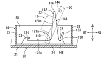
[Seventh Embodiment] FIG. 21 is a side sectional view showing the main part of the fuel tank, and FIG. As shown in FIG. 21, the guide pin (reference numeral 110) on the front side of the mount 30 of the pump unit 16 of the present embodiment is formed in an oval shaft shape, for example. The major axis direction of the front guide pin 110 is oriented in the same direction as the longitudinal direction of the mount 30. Further, the guide pin (reference numeral 112) on the rear side of the mount 30 is formed in a square shaft shape, for example.

本実施形態のガイドレール(符号、114を付す)は、実施形態1(図1〜図6参照)のサブタンク14の底板部24上に左右対称的(図21では左側のガイドレール114のみを示す)に設けられている。ガイドレール114は、前側のガイド面116及び後側のガイド面118を有する山形状に形成されている。ガイドレール114の上端部は、サブタンク14の水平状態での燃料を貯留可能な高さ位置よりも上方へ延出されている。また、ガイドレール114の上端部は、タンク本体12のタンクホール22の中央部の下方付近に向けて延びている。   The guide rail of this embodiment (reference numeral 114) is symmetrical on the bottom plate portion 24 of the sub tank 14 of the first embodiment (see FIGS. 1 to 6) (only the left guide rail 114 is shown in FIG. 21). ). The guide rail 114 is formed in a mountain shape having a front guide surface 116 and a rear guide surface 118. The upper end portion of the guide rail 114 extends upward from a height position where the fuel in the horizontal state of the sub tank 14 can be stored. Further, the upper end portion of the guide rail 114 extends toward the vicinity of the lower portion of the central portion of the tank hole 22 of the tank body 12.

前側のガイド面116は、タンク本体12のタンクホール22側から底部側の斜め前方に向けて延在している。前側のガイド面116は、急な斜面からなる前側の上流ガイド部120と、前側の上流ガイド部120の下端部に傾斜ガイド部121を介して連続されかつ前方へ延びる前側の下流ガイド部122とを有している。傾斜ガイド部121は、凹型円弧状に形成されている。ガイドレール114の前端部には、前側の下流ガイド部122の前端に連続しかつ後方を開口する横向きU字状の係止溝124を有する係止壁部123が形成されている。   The front guide surface 116 extends obliquely forward on the bottom side from the tank hole 22 side of the tank body 12. The front guide surface 116 includes a front upstream guide portion 120 formed of a steep slope, a front downstream guide portion 122 that is continuous with the lower end portion of the front upstream guide portion 120 via the inclined guide portion 121 and extends forward. have. The inclined guide part 121 is formed in a concave arc shape. A locking wall portion 123 having a lateral U-shaped locking groove 124 that is continuous with the front end of the downstream guide portion 122 on the front side and opens rearward is formed at the front end portion of the guide rail 114.

後側のガイド面118は、タンク本体12のタンクホール22側から底部側の斜め後方に向けて延在している。後側のガイド面118は、急な斜面からなる後側の上流ガイド部126と、後側の上流ガイド部126に連続する円弧状の後側の下流ガイド部128とを有している。後側の下流ガイド部128は、係止壁部123に係合した状態での前側のガイドピン110を中心とするマウント30の上下方向の回動にともなう後側のガイドピン112の回動軌跡に略倣う曲率半径で形成されている。また、前後の上流ガイド部120,126は、前後対称的に形成されている。   The rear guide surface 118 extends from the tank hole 22 side of the tank body 12 obliquely rearward on the bottom side. The rear guide surface 118 includes a rear upstream guide portion 126 formed of a steep slope, and an arcuate rear downstream guide portion 128 continuous with the rear upstream guide portion 126. The downstream guide portion 128 on the rear side rotates the locus of the guide pin 112 on the rear side when the mount 30 rotates in the vertical direction around the front guide pin 110 in the state of being engaged with the locking wall portion 123. Is formed with a radius of curvature that substantially follows. The front and rear upstream guide portions 120 and 126 are formed symmetrically in the front-rear direction.

ガイドレール114の後端部には、後側の下流ガイド部128の下端に連続しかつ上方を開口する四角形溝状のロック溝131を有するロック部130が形成されている。ロック部130には、前方に突出するロック爪132が形成されている。ロック部130のロック爪132より上方へ突出する部分は、操作部133とされている。ロック部130は、前後方向に弾性変形すなわち撓み変形可能に形成されている(図22中、二点鎖線130参照)。ロック爪132は、ロック溝131に係合した後側のガイドピン112に対してロック部130の弾性変形を利用して係合可能に形成されている。   At the rear end portion of the guide rail 114, a lock portion 130 having a rectangular groove-like lock groove 131 that is continuous with the lower end of the rear downstream guide portion 128 and opens upward is formed. The lock part 130 is formed with a lock claw 132 protruding forward. A portion protruding upward from the lock claw 132 of the lock portion 130 is an operation portion 133. The lock part 130 is formed so as to be elastically deformable, that is, bendable in the front-rear direction (see the two-dot chain line 130 in FIG. 22). The lock claw 132 is formed so as to be engageable with the guide pin 112 on the rear side engaged with the lock groove 131 by utilizing elastic deformation of the lock portion 130.

図21に示すように、後側のガイドピン112とロック部130とにより、ロック手段135が構成されている。また、係止壁部123を本明細書でいう「タンク本体側支持部」とし、前側のガイドピン110を本明細書でいう「ポンプユニット側支持部」として、相互に回動可能にかつ係脱可能に係合する回動支持手段137が構成されている。また、両ガイドピン110,112とガイドレール114とにより、ガイド手段が構成されている。ガイド手段は、左右対称的(図21及び図22では一方のみを示す)に配置されている。   As shown in FIG. 21, the locking means 135 is configured by the rear guide pin 112 and the lock portion 130. In addition, the locking wall portion 123 is referred to as a “tank main body side support portion” in the present specification, and the front guide pin 110 is referred to as a “pump unit side support portion” in the present specification so as to be rotatable with respect to each other. Rotating support means 137 that is detachably engaged is configured. The guide pins 110 and 112 and the guide rail 114 constitute guide means. The guide means are arranged symmetrically (only one is shown in FIGS. 21 and 22).

また、本実施形態では、サブタンク14の左側板部25、右側板部(不図示)、前側板部27及び後側板部28の上端面は、同一高さで形成されている。また、左側板部25(及び右側板部)には、実施形態1の突出部25a,26a(図5及び図6参照)は形成されていない。また、実施形態1と異なり、サブタンク14に対するポンプユニット16の組付け状態(図21参照)において、マウント30の前端部は、前側板部27に対して近接又は当接しなくてもよい。また、マウント30の後端部は、後側板部28に対して近接又は当接しなくてもよい。また、本実施形態において、実施形態1のマウント30の円弧状面34a及び傾斜状面34b(図4参照)は、省略されている。また、図21及び図22において、フランジユニット18、ポンプユニット16における支持側板34及び台板36、燃料フィルタ38、プレッシャレギュレータ42等は省略されている。   In the present embodiment, the left side plate portion 25, the right side plate portion (not shown), the front side plate portion 27, and the rear side plate portion 28 of the sub tank 14 are formed at the same height. Further, the left side plate portion 25 (and the right side plate portion) is not formed with the protruding portions 25a and 26a (see FIGS. 5 and 6) of the first embodiment. Further, unlike the first embodiment, the front end portion of the mount 30 does not have to be close to or abut on the front plate portion 27 in the assembled state of the pump unit 16 with respect to the sub tank 14 (see FIG. 21). Further, the rear end portion of the mount 30 may not be close to or in contact with the rear side plate portion 28. In the present embodiment, the arcuate surface 34a and the inclined surface 34b (see FIG. 4) of the mount 30 of the first embodiment are omitted. 21 and 22, the flange unit 18, the support side plate 34 and the base plate 36 in the pump unit 16, the fuel filter 38, the pressure regulator 42, and the like are omitted.

なお、前側のガイドピン110は本明細書でいう「摺動子」、「先行側摺動子」、「ポンプユニット側支持部」に相当する。また、後側のガイドピン112は本明細書でいう「摺動子」、「後行側摺動子」に相当する。なお、後側のガイドピン112は本明細書でいう「ポンプユニット側ロック部」に相当する。また、前側の上流ガイド部120及び後側の上流ガイド部126は、本明細書でいう「第1ガイド部」に相当する。また、前側の下流ガイド部122は、本明細書でいう「第3ガイド部」に相当する。また、後側の下流ガイド部128は、本明細書でいう「第2ガイド部」に相当する。また、ロック部130は本明細書でいう「タンク本体側ロック部」に相当する。   The front guide pin 110 corresponds to “slider”, “preceding side slider”, and “pump unit side support portion” in this specification. The rear guide pin 112 corresponds to a “slider” and a “rear slider” in this specification. The rear guide pin 112 corresponds to the “pump unit side lock portion” in this specification. The front upstream guide portion 120 and the rear upstream guide portion 126 correspond to a “first guide portion” in this specification. The front downstream guide portion 122 corresponds to a “third guide portion” in this specification. In addition, the rear downstream guide portion 128 corresponds to a “second guide portion” in this specification. The lock unit 130 corresponds to a “tank body side lock unit” in this specification.

次に、タンク本体12に対するポンプユニット16の組付け方法について説明する。ポンプユニット16を、長手方向の一端部(前端部)を斜め前方へ傾かせた略垂直姿勢としてタンク本体12に挿入する。このとき、前側のガイドピン110を、サブタンク14のガイドレール114の前側の上流ガイド部120に係合させ、その前側の上流ガイド部120に沿って下方へ摺動させていく。続いて、前側のガイドピン110を、前側の上流ガイド部120から傾斜ガイド部121に摺動させる(図22参照)。この状態から、前側のガイドピン110を前側の下流ガイド部122に沿って前方へ移動させつつ、後側のガイドピン112をガイドレール114の後側の上流ガイド部126に係合させ、その後側の上流ガイド部126に沿って下方へ摺動させていく。すると、前側のガイドピン110がガイドレール114の係止壁部123の係止溝124に係合する。   Next, a method for assembling the pump unit 16 to the tank body 12 will be described. The pump unit 16 is inserted into the tank body 12 in a substantially vertical posture in which one end portion (front end portion) in the longitudinal direction is inclined obliquely forward. At this time, the front guide pin 110 is engaged with the upstream upstream guide portion 120 of the guide rail 114 of the sub tank 14 and is slid downward along the upstream upstream guide portion 120. Subsequently, the front guide pin 110 is slid from the front upstream guide portion 120 to the inclined guide portion 121 (see FIG. 22). From this state, the front guide pin 110 is moved forward along the front downstream guide portion 122 while the rear guide pin 112 is engaged with the rear upstream guide portion 126 of the guide rail 114, and the rear side. The upper guide part 126 is slid downward. Then, the front guide pin 110 engages with the locking groove 124 of the locking wall portion 123 of the guide rail 114.

続いて、係止壁部123と前側のガイドピン110との係合による回動支持手段137(図21参照)を回動支点として、ポンプユニット16を下方へ回動させる。すなわち、ポンプユニット16の後端部を押し下げていく。すると、後側のガイドピン112が後側の下流ガイド部128を摺動していく。そして、ガイドレール114のロック部130のロック爪132に後側のガイドピン112が当接すると、ロック部130が後方へ弾性変形(図21中、二点鎖線130参照)されていき、後側のガイドピン112がロック爪132を通過すると同時にロック部130が弾性復元し、後側のガイドピン112にロック爪132が係合いわゆるスナップフィット係合される(図21参照)。これにより、タンク本体12にポンプユニット16がロックされる。   Subsequently, the pump unit 16 is rotated downward using the rotation support means 137 (see FIG. 21) by the engagement between the locking wall portion 123 and the front guide pin 110 as a rotation fulcrum. That is, the rear end portion of the pump unit 16 is pushed down. Then, the rear guide pin 112 slides on the rear downstream guide portion 128. When the rear guide pin 112 comes into contact with the lock claw 132 of the lock portion 130 of the guide rail 114, the lock portion 130 is elastically deformed rearward (see the two-dot chain line 130 in FIG. 21), and the rear side As soon as the guide pin 112 passes through the lock claw 132, the lock portion 130 is elastically restored, and the lock claw 132 is engaged with the rear guide pin 112 so-called snap-fit engagement (see FIG. 21). As a result, the pump unit 16 is locked to the tank body 12.

また、ポンプユニット16を取外したい場合には、ロック部130の操作部133を後方へ押すことにより、後側のガイドピン112に対するロック爪132の係合を解除(図21中、二点鎖線130参照)した後、回動支持手段137を回動支点として、ポンプユニット16を上方へ回動させる。すなわち、ポンプユニット16の後端部を引き上げる。以降、挿入時とは逆順で、ポンプユニット16を取外せばよい。   When the pump unit 16 is desired to be removed, the lock claw 132 is disengaged from the rear guide pin 112 by pushing the operation portion 133 of the lock portion 130 rearward (in FIG. 21, a two-dot chain line 130). After that, the pump unit 16 is rotated upward using the rotation support means 137 as a rotation fulcrum. That is, the rear end portion of the pump unit 16 is pulled up. Thereafter, the pump unit 16 may be removed in the reverse order of insertion.

前記した燃料タンク10によると、タンク本体12内にポンプユニット16を組付ける際に、ガイド手段のガイドレール114によって両ガイドピン110,112がガイドされる。これによって、ポンプユニット16がタンク本体12のタンクホール22側から底部側の組付け位置までガイドされる。したがって、ポンプユニット16を迷わずに容易に組付け位置へ適正に移動させることができる。このため、作業時間を短縮するとともに、ポンプユニット16の組付け不良を抑制することができる。よって、タンク本体12に対するポンプユニット16の組付け性を向上することができる。   According to the fuel tank 10 described above, when the pump unit 16 is assembled in the tank body 12, the guide pins 110 and 112 are guided by the guide rail 114 of the guide means. As a result, the pump unit 16 is guided from the tank hole 22 side of the tank body 12 to the assembly position on the bottom side. Therefore, the pump unit 16 can be easily moved appropriately to the assembly position without hesitation. For this reason, while shortening working time, the assembly | attachment defect of the pump unit 16 can be suppressed. Therefore, the assembling property of the pump unit 16 to the tank body 12 can be improved.

また、ポンプユニット16の長手方向の一端部を回動可能に支持する回動支持手段137が、タンク本体12側に設けられた係止壁部123(タンク本体側支持部)と、ポンプユニット16側に設けられかつ係止壁部123に係合される前側のガイドピン110(ポンプユニット側支持部)とにより構成されている。また、ガイドレール55には、タンク本体12のタンクホール22側から底部側に延在する前側の上流ガイド部120及び後側の上流ガイド部126が設けられている。したがって、ポンプユニット16の前側のガイドピン110及び後側のガイドピン112をタンク本体12のタンクホール22側から底部側にガイドすることができる。また、回動支持手段137の係止壁部123(タンク本体側支持部)と前側のガイドピン110(ポンプユニット側支持部)との係合により、ポンプユニット16の長手方向の一端部(前端部)を回動可能に支持することができる。よって、回動支持手段137を回動支点として、ポンプユニット16をタンク本体12の底部側の組付け位置に容易に回動させることができる。   Further, a rotation support means 137 that rotatably supports one end portion of the pump unit 16 in the longitudinal direction includes a locking wall portion 123 (tank body side support portion) provided on the tank body 12 side, and the pump unit 16. It is comprised by the front guide pin 110 (pump unit side support part) provided in the side and engaged with the latching wall part 123. FIG. The guide rail 55 is provided with a front upstream guide portion 120 and a rear upstream guide portion 126 that extend from the tank hole 22 side to the bottom side of the tank body 12. Therefore, the front guide pin 110 and the rear guide pin 112 of the pump unit 16 can be guided from the tank hole 22 side to the bottom side of the tank body 12. Further, the engagement of the locking wall portion 123 (tank body side support portion) of the rotation support means 137 and the front guide pin 110 (pump unit side support portion) causes one end portion (front end) of the pump unit 16 in the longitudinal direction. Part) can be rotatably supported. Therefore, the pump unit 16 can be easily rotated to the assembly position on the bottom side of the tank body 12 with the rotation support means 137 as a rotation fulcrum.

また、後側の上流ガイド部126の底部側端部に連続され、回動支持手段137を回動支点としてポンプユニット16を下方へ回動させる際に後側のガイドピン112をガイドする後側の下流ガイド部128が設けられている。したがって、回動支持手段137を回動支点としてポンプユニット16を回動させることにより、後側のガイドピン112がガイドレール55の後側の下流ガイド部128によりガイドされる。このため、ポンプユニット16をタンク本体12の底部側の組付け位置に容易に移動させることができる。   Further, the rear side is continuous with the bottom side end portion of the rear upstream guide portion 126 and guides the rear guide pin 112 when the pump unit 16 is rotated downward with the rotation support means 137 as a rotation fulcrum. The downstream guide portion 128 is provided. Accordingly, by rotating the pump unit 16 using the rotation support means 137 as a rotation fulcrum, the rear guide pin 112 is guided by the rear downstream guide portion 128 of the guide rail 55. For this reason, the pump unit 16 can be easily moved to the assembly position on the bottom side of the tank body 12.

また、タンク本体12とポンプユニット16との間には、回動支持手段137を回動支点としてポンプユニット16をタンク本体12の底部側の組付け位置に回動したときに、相互に係合するロック手段135が設けられている。ロック手段135は、タンク本体12側に設けられたロック部130と、ポンプユニット16側に設けられかつロック部130に係合される後側のガイドピン112とを備えている。ロック部130と後側のガイドピン112とは、ロック部130の弾性変形を利用して係合可能に構成されている。したがって、ポンプユニット16をタンク本体12の底部側の組付け位置に回動したときには、ロック手段135のロック部130に後側のガイドピン112がロック部130の弾性変形を利用して係合することによって、タンク本体12にポンプユニット16がロックされる。また、ロック部130に対する後側のガイドピン112の係合をロック部130の弾性変形を利用して解除することによって、ポンプユニット16を挿入時とは逆順で取外すことができる。よって、ポンプユニット16をタンク本体12に着脱可能に組付けることができる。   Further, the tank body 12 and the pump unit 16 are engaged with each other when the pump unit 16 is rotated to the assembly position on the bottom side of the tank body 12 with the rotation support means 137 as a rotation fulcrum. Locking means 135 is provided. The lock means 135 includes a lock portion 130 provided on the tank body 12 side, and a rear guide pin 112 provided on the pump unit 16 side and engaged with the lock portion 130. The lock part 130 and the rear guide pin 112 are configured to be engageable by utilizing elastic deformation of the lock part 130. Therefore, when the pump unit 16 is rotated to the assembly position on the bottom side of the tank body 12, the rear guide pin 112 engages with the lock portion 130 of the lock means 135 by utilizing elastic deformation of the lock portion 130. As a result, the pump unit 16 is locked to the tank body 12. Further, by releasing the engagement of the guide pin 112 on the rear side with respect to the lock portion 130 using the elastic deformation of the lock portion 130, the pump unit 16 can be removed in the reverse order of insertion. Therefore, the pump unit 16 can be detachably assembled to the tank body 12.

また、ポンプユニット16の長手方向の一端部に、前側のガイドピン110が設けられ、ガイドレール55には、前側の上流ガイド部120の底部側端部に傾斜ガイド部121を介して連続され、前側のガイドピン110をタンク本体12の底部に沿って所定位置までガイドする前側の下流ガイド部122が設けられている。したがって、前側のガイドピン110を、ガイドレール55の前側の下流ガイド部122によって、回動支持手段137に向けてガイドすることができる。   Further, a front guide pin 110 is provided at one end of the pump unit 16 in the longitudinal direction, and the guide rail 55 is continued to the bottom side end of the front upstream guide 120 via an inclined guide 121. A front downstream guide portion 122 that guides the front guide pin 110 along the bottom of the tank body 12 to a predetermined position is provided. Therefore, the front guide pin 110 can be guided toward the rotation support means 137 by the front downstream guide portion 122 of the guide rail 55.

また、前側のガイドピン110は、回動支持手段137のポンプユニット側支持部を兼用するように構成されている。したがって、ポンプユニット側支持部として、特別な部材を設けなくて済む。また、係止壁部123を、回動支持手段137のタンク本体側支持部とすることによって、タンク本体側支持部として特別な部材を設けなくて済む。   Further, the front guide pin 110 is configured to also serve as a pump unit side support portion of the rotation support means 137. Therefore, it is not necessary to provide a special member as the pump unit side support portion. Further, by using the locking wall portion 123 as the tank body side support portion of the rotation support means 137, it is not necessary to provide a special member as the tank body side support portion.

[実施形態8]図23は燃料タンクの要部を示す側断面図である。図23に示すように、本実施形態では、実施形態7(図21参照)のサブタンク14とタンクホール22とが前後方向(図23において左右方向)にオフセットして配置されている。そして、ガイドレール114の両ガイド面116,118の山形状が、その上端部をタンク本体12のタンクホール22の中央部の下方付近に向けて延びる傾斜状に形成されている。したがって、サブタンク14とタンクホール22とがオフセットして配置されていても、タンク本体12内にポンプユニット16を容易に組付けることができる。また、本実施形態のサブタンク(符号、140を付す)では、実施形態7(図21参照)のサブタンク14の後側板部28が省略されている。 [Eighth Embodiment] FIG. 23 is a side sectional view showing a main part of a fuel tank. As shown in FIG. 23, in this embodiment, the sub tank 14 and the tank hole 22 of Embodiment 7 (see FIG. 21) are arranged offset in the front-rear direction (left-right direction in FIG. 23). And the mountain shape of both guide surfaces 116 and 118 of the guide rail 114 is formed in the inclined shape extended toward the downward vicinity of the center part of the tank hole 22 of the tank main body 12 in the upper end part. Therefore, even if the sub tank 14 and the tank hole 22 are arranged offset, the pump unit 16 can be easily assembled in the tank body 12. Further, in the sub tank of this embodiment (reference numeral 140), the rear side plate portion 28 of the sub tank 14 of Embodiment 7 (see FIG. 21) is omitted.

[実施形態9]図24は燃料タンクの要部を示す側断面図である。図24に示すように、本実施形態では、実施形態7(図21参照)のガイドレール114の前側のガイド面116の形状が、簡略化された形状の前側のガイド面(符号、142を付す)に変更されている。すなわち、傾斜ガイド部(符号、121aを付す)の曲率半径が小径化されているとともに、前側の上流ガイド部(符号、120aを付す)及び前側の下流ガイド部(符号、122aを付す)が直線状に形成されている。また、実施形態7(図21参照)の後側のガイド面118が、簡略化された形状の後側のガイド面(符号、144を付す)に変更されている。すなわち、後側のガイド面144は、上端から下端まで直線状に形成されている。なお、後側のガイド面144は本明細書でいう「第1ガイド部」に相当する。 [Embodiment 9] FIG. 24 is a side sectional view showing an essential part of a fuel tank. As shown in FIG. 24, in this embodiment, the shape of the front guide surface 116 of the guide rail 114 of the seventh embodiment (see FIG. 21) is a simplified front guide surface (reference numeral 142). ) Has been changed. That is, the radius of curvature of the inclined guide portion (referenced by 121a) is reduced, and the front upstream guide portion (referenced by 120a) and the front downstream guide portion (referenced by 122a) are straight. It is formed in a shape. In addition, the rear guide surface 118 of the seventh embodiment (see FIG. 21) is changed to a simplified guide rear guide surface (reference numeral 144). That is, the rear guide surface 144 is linearly formed from the upper end to the lower end. The rear guide surface 144 corresponds to a “first guide portion” in this specification.

また、実施形態7(図21参照)のマウント30の後側のガイドピン112が、例えば丸軸形状の後側のガイドピン(符号、146を付す)に変更されている。これにともない、実施形態7(図21参照)のガイドレール114のロック溝(符号、148を付す)がU字溝状に形成されている。なお、後側のガイドピン146は本明細書でいう「摺動子」、「後行側摺動子」、「ポンプユニット側ロック部」に相当する。   Further, the rear guide pin 112 of the mount 30 of the seventh embodiment (see FIG. 21) is changed to, for example, a rear guide pin (reference numeral 146) having a round shaft shape. Accordingly, the lock groove (reference numeral 148) of the guide rail 114 of the seventh embodiment (see FIG. 21) is formed in a U-shaped groove shape. The rear guide pin 146 corresponds to “slider”, “rear-side slider”, and “pump unit side lock portion” in the present specification.

[実施形態10]図25は燃料タンクの要部を示す側断面図である。図25に示すように、本実施形態は、実施形態7(図21参照)のサブタンク14を省略し、ガイドレール114をタンク本体12の底面部21上に配置したものである。 [Embodiment 10] FIG. 25 is a side sectional view showing a main portion of a fuel tank. As shown in FIG. 25, in the present embodiment, the sub tank 14 of the seventh embodiment (see FIG. 21) is omitted, and the guide rail 114 is disposed on the bottom surface portion 21 of the tank main body 12.

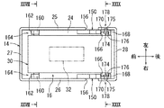
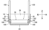
[実施形態11]図26は燃料タンクの要部を示す側断面図、図27はサブタンクに対するポンプユニットの組付け状態を示す平面図、図28は図27のXXVIII−XXVIII線矢視断面図、図29は図27のXXIX−XXIX線矢視断面図である。図26に示すように、本実施形態は、実施形態7(図21参照)のガイドレール114を、ガイドレール(符号、150を付す)に変更している。ガイドレール150は、実施形態7のガイドレール114から前側の下流ガイド部122、係止壁部123、及び、ロック部130を含む下端部が省略されたものとなっている。 [Embodiment 11] FIG. 26 is a side sectional view showing the main part of the fuel tank, FIG. 27 is a plan view showing the assembled state of the pump unit to the sub tank, and FIG. 28 is a sectional view taken along the line XXVIII-XXVIII in FIG. 29 is a cross-sectional view taken along line XXIX-XXIX in FIG. As shown in FIG. 26, in the present embodiment, the guide rail 114 of the seventh embodiment (see FIG. 21) is changed to a guide rail (reference numeral 150). In the guide rail 150, the lower end portion including the downstream guide portion 122, the locking wall portion 123, and the lock portion 130 on the front side from the guide rail 114 of the seventh embodiment is omitted.

ガイドレール150の前側のガイド面(符号、151を付す)の前側の上流ガイド部(符号、152を付す)は、直線状に形成されている。また、傾斜ガイド部(符号、153を付す)は、直線状に形成されている。後側のガイド面(符号、154を付す)は、上端から下端まで鉛直方向に延在する直線状に形成されている。ガイドレール150は、サブタンク14の左側板部25及び右側板部26の内側面に沿って配置されている(図27〜図29参照)。図27に示すように、左側板部25及び右側板部26には、ガイドレール150によって閉鎖される切欠き部156が開口されている。なお、切欠き部156は省略してもよい。   The upstream guide portion (reference numeral 152) of the front guide surface (reference numeral 151) of the guide rail 150 is formed in a straight line. Further, the inclined guide portion (reference numeral 153) is formed in a straight line. The rear guide surface (reference numeral 154) is formed in a straight line extending in the vertical direction from the upper end to the lower end. The guide rail 150 is disposed along the inner side surface of the left side plate portion 25 and the right side plate portion 26 of the sub tank 14 (see FIGS. 27 to 29). As shown in FIG. 27, the left plate portion 25 and the right plate portion 26 have a notch 156 that is closed by the guide rail 150. Note that the notch 156 may be omitted.

図28に示すように、マウント30の前部の左右両側端部には、下方へ突出する左右一対の脚片158が設けられている。脚片158は、四角形板状で、下端部の前後両角部が半円弧状に丸められている(図26参照)。脚片158の外側面には、前側のガイドピン(符号、160を付す)が配置されている。   As shown in FIG. 28, a pair of left and right leg pieces 158 projecting downward are provided at the left and right end portions of the front portion of the mount 30. The leg piece 158 has a quadrangular plate shape, and both front and rear corners of the lower end are rounded into a semicircular arc (see FIG. 26). On the outer surface of the leg piece 158, a front guide pin (reference numeral 160) is disposed.

図27及び図28に示すように、サブタンク14の底板部24の前部上には、左右一対の係止片162が左右対称的に設けられている。左側の係止片162は、サブタンク14の底板部24と左側板部25とのなす隅角部に配置されている。右側の係止片162は、サブタンク14の底板部24と右側板部26とのなす隅角部に配置されている。両係止片162は、いずれも後方に開口する逆L字形状に形成されており、ガイドピン160を後方から係合可能である(図26参照)。係止片162を本明細書でいう「タンク本体側支持部」とし、ガイドピン160を本明細書でいう「ポンプユニット側支持部」として、相互に回動可能にかつ係脱可能に係合する回動支持手段164が構成されている(図26〜図28参照)。   As shown in FIGS. 27 and 28, a pair of left and right engaging pieces 162 are symmetrically provided on the front portion of the bottom plate portion 24 of the sub tank 14. The left locking piece 162 is disposed at a corner portion formed by the bottom plate portion 24 and the left plate portion 25 of the sub tank 14. The right locking piece 162 is arranged at a corner formed by the bottom plate portion 24 and the right plate portion 26 of the sub tank 14. Both the locking pieces 162 are formed in an inverted L shape that opens rearward, and the guide pins 160 can be engaged from the rear (see FIG. 26). The locking piece 162 is a “tank body side support portion” as used in this specification, and the guide pin 160 is a “pump unit side support portion” as used in this specification so that they can rotate and detachably engage with each other. Rotating support means 164 is configured (see FIGS. 26 to 28).

図27に示すように、マウント30の後端部の左右両側面には、左右一対のガイド片166が設けられている。ガイド片166は、縦長の四角形板状で、下端部がマウント30より下方へ突出されている(図26参照)。ガイド片166の下端部の前後両角部が半円弧状に丸められている。また、サブタンク14の底板部24の後部上には、左右一対の規制片168が左右対称的に設けられている(図29参照)。左側の規制片168は、サブタンク14の底板部24と左側板部25とのなす隅角部に配置されている。右側の規制片168は、サブタンク14の底板部24と右側板部26とのなす隅角部に配置されている。両規制片168は、いずれも両ガイドレール150の後側のガイド面154に面する突片状に形成されている(図26参照)。サブタンク14の底板部24上において、両規制片168と両ガイドレール150との間には、ガイド片166を上方から係合可能とする係合溝170が形成されている。   As shown in FIG. 27, a pair of left and right guide pieces 166 are provided on the left and right side surfaces of the rear end portion of the mount 30. The guide piece 166 has a vertically long rectangular plate shape, and a lower end portion projects downward from the mount 30 (see FIG. 26). Both front and rear corners of the lower end of the guide piece 166 are rounded into a semicircular arc. A pair of left and right restricting pieces 168 are provided symmetrically on the rear portion of the bottom plate portion 24 of the sub tank 14 (see FIG. 29). The left regulation piece 168 is disposed at a corner portion formed by the bottom plate portion 24 and the left plate portion 25 of the sub tank 14. The right regulation piece 168 is disposed at a corner portion formed by the bottom plate portion 24 and the right plate portion 26 of the sub tank 14. Both restriction pieces 168 are formed in a protruding piece shape facing the guide surface 154 on the rear side of both guide rails 150 (see FIG. 26). On the bottom plate portion 24 of the sub tank 14, an engagement groove 170 is formed between the restriction pieces 168 and the guide rails 150 so that the guide pieces 166 can be engaged from above.

図29に示すように、サブタンク14の左側板部25及び右側板部26の後上部の内側面には、ロック凹部172が形成されている(図26参照)。ロック凹部172は、横向きの有底穴形状に形成されているが、貫通孔形状に変更してもよい。一方、マウント30の両ガイド片166上には、左右一対のロック片174が左右対称的に設けられている。ロック片174の中央部には、外側方に突出するロック爪175が形成されている。ロック片174のロック爪175より上方へ突出する部分は、操作部176とされている。ロック片174は、左右方向に弾性変形すなわち撓み変形可能に形成されている(図29中、二点鎖線176参照)。ロック爪175は、サブタンク14のロック凹部172に対してロック片174の弾性変形を利用して係合可能に形成されている。ロック凹部172とロック片174とにより、ロック手段178が構成されている。   As shown in FIG. 29, a lock recess 172 is formed on the inner surface of the rear upper portion of the left side plate portion 25 and the right side plate portion 26 of the sub tank 14 (see FIG. 26). The lock recess 172 is formed in a laterally-bottomed hole shape, but may be changed to a through-hole shape. On the other hand, a pair of left and right locking pieces 174 are provided symmetrically on both guide pieces 166 of the mount 30. A lock claw 175 protruding outward is formed at the center of the lock piece 174. A portion of the lock piece 174 that protrudes upward from the lock claw 175 is an operation portion 176. The lock piece 174 is formed to be elastically deformable, that is, bendable in the left-right direction (see the two-dot chain line 176 in FIG. 29). The lock claw 175 is formed so as to be engageable with the lock recess 172 of the sub tank 14 by utilizing elastic deformation of the lock piece 174. The lock recess 172 and the lock piece 174 constitute a lock means 178.

なお、後側のガイド面154は本明細書でいう「第1ガイド部」に相当する。また、ガイドピン160は本明細書でいう「摺動子」、「先行側摺動子」、「ポンプユニット側支持部」に相当する。また、ガイド片166は本明細書でいう「摺動子」、「後行側摺動子」に相当する。また、ロック凹部172は本明細書でいう「ポンプユニット側ロック部」に相当する。また、ロック片174は本明細書でいう「タンク本体側ロック部」に相当する。また、タンク本体12の底面部21は本明細書でいう「第3ガイド部材」に相当する。   The rear guide surface 154 corresponds to a “first guide portion” in this specification. Further, the guide pin 160 corresponds to “slider”, “preceding side slider”, and “pump unit side support portion” in this specification. The guide piece 166 corresponds to a “slider” and a “successor-side slider” in the present specification. Further, the lock recess 172 corresponds to a “pump unit side lock portion” in this specification. Further, the lock piece 174 corresponds to a “tank body side lock portion” in this specification. Further, the bottom surface portion 21 of the tank body 12 corresponds to a “third guide member” in this specification.

次に、タンク本体12に対するポンプユニット16の組付け方法について説明する。ポンプユニット16を、長手方向の一端部(前端部)を斜め前方へ傾かせた略垂直姿勢としてタンク本体12に挿入する。このとき、ガイドピン160を、サブタンク14のガイドレール150の前側の上流ガイド部152に係合させ、その前側の上流ガイド部152に沿って下方へ摺動させていく。続いて、ガイドピン160を、前側の上流ガイド部152から傾斜ガイド部153に摺動させる。この状態から、ガイドピン160をタンク本体12の底面部21に沿って前方へ移動させつつ、ガイド片166をガイドレール150の後側のガイド面154に係合させ、そのガイド面154に沿って下方へ摺動させていく。すると、ガイドピン160がサブタンク14の係止片162に係合する。   Next, a method for assembling the pump unit 16 to the tank body 12 will be described. The pump unit 16 is inserted into the tank body 12 in a substantially vertical posture in which one end portion (front end portion) in the longitudinal direction is inclined obliquely forward. At this time, the guide pin 160 is engaged with the upstream upstream guide portion 152 of the guide rail 150 of the sub tank 14 and is slid downward along the upstream upstream guide portion 152. Subsequently, the guide pin 160 is slid from the front upstream guide portion 152 to the inclined guide portion 153. From this state, while moving the guide pin 160 forward along the bottom surface portion 21 of the tank body 12, the guide piece 166 is engaged with the guide surface 154 on the rear side of the guide rail 150, and along the guide surface 154. Slide down. Then, the guide pin 160 engages with the locking piece 162 of the sub tank 14.

続いて、係止片162とガイドピン160との係合による回動支持手段164(図26参照)を回動支点として、ポンプユニット16を下方へ回動させる。すなわち、ポンプユニット16の後端部を押し下げていく。そして、サブタンク14の左側板部25及び右側板部26に、ロック片174のロック爪175が当接すると、ロック片174が内側方へ弾性変形(図29中、二点鎖線174参照)されていき、サブタンク14のロック凹部172にロック爪175が整合すると同時に、ロック部130が弾性復元し、ロック凹部172にロック爪175が係合いわゆるスナップフィット係合される(図29参照)。これと同時に、サブタンク14の係合溝170にガイド片166が係合する(図26参照)。これにより、タンク本体12にポンプユニット16がロックされる。   Subsequently, the pump unit 16 is rotated downward using the rotation support means 164 (see FIG. 26) by the engagement between the locking piece 162 and the guide pin 160 as a rotation fulcrum. That is, the rear end portion of the pump unit 16 is pushed down. When the lock claw 175 of the lock piece 174 comes into contact with the left side plate portion 25 and the right side plate portion 26 of the sub tank 14, the lock piece 174 is elastically deformed inward (see a two-dot chain line 174 in FIG. 29). The lock claw 175 aligns with the lock recess 172 of the sub tank 14, and at the same time, the lock portion 130 is elastically restored, and the lock claw 175 is engaged with the lock recess 172, so-called snap fit engagement (see FIG. 29). At the same time, the guide piece 166 engages with the engagement groove 170 of the sub tank 14 (see FIG. 26). As a result, the pump unit 16 is locked to the tank body 12.

また、ポンプユニット16を取外したい場合には、ロック片174の操作部176を内側方へ押すことにより、ロック凹部172に対するロック爪175の係合を解除(図29中、二点鎖線175参照)した後、回動支持手段164を回動支点として、ポンプユニット16を上方へ回動させる。すなわち、ポンプユニット16の後端部を引き上げる。以降、挿入時とは逆順で、ポンプユニット16を取外せばよい。   When the pump unit 16 is to be removed, the lock claw 175 is disengaged from the lock recess 172 by pushing the operation portion 176 of the lock piece 174 inward (see the two-dot chain line 175 in FIG. 29). After that, the pump unit 16 is rotated upward with the rotation support means 164 as a rotation fulcrum. That is, the rear end portion of the pump unit 16 is pulled up. Thereafter, the pump unit 16 may be removed in the reverse order of insertion.

前記した燃料タンク10によると、タンク本体12内にポンプユニット16を組付ける際に、ガイド手段のガイドレール150によってガイドピン160及びガイド片166がガイドされる。これによって、ポンプユニット16がタンク本体12のタンクホール22側から底部側の組付け位置までガイドされる。したがって、ポンプユニット16を迷わずに容易に組付け位置へ適正に移動させることができる。このため、作業時間を短縮するとともに、ポンプユニット16の組付け不良を抑制することができる。よって、タンク本体12に対するポンプユニット16の組付け性を向上することができる。   According to the fuel tank 10 described above, when the pump unit 16 is assembled in the tank body 12, the guide pin 160 and the guide piece 166 are guided by the guide rail 150 of the guide means. As a result, the pump unit 16 is guided from the tank hole 22 side of the tank body 12 to the assembly position on the bottom side. Therefore, the pump unit 16 can be easily moved appropriately to the assembly position without hesitation. For this reason, while shortening working time, the assembly | attachment defect of the pump unit 16 can be suppressed. Therefore, the assembling property of the pump unit 16 to the tank body 12 can be improved.

また、ポンプユニット16の長手方向の一端部を回動可能に支持する回動支持手段164が、タンク本体12側に設けられた係止片162(タンク本体側支持部)と、ポンプユニット16側に設けられかつ係止片162に係合されるガイドピン160(ポンプユニット側支持部)とにより構成されている。また、ガイドレール150には、前側の上流ガイド部152及び後側のガイド面154が設けられている。したがって、ガイドレール150の前側の上流ガイド部152及び後側のガイド面154により、ポンプユニット16のガイドピン160及びガイド片166を上端部側から底部側にガイドすることができる。また、回動支持手段164の係止片162(タンク本体側支持部)とガイドピン160(ポンプユニット側支持部)との係合により、ポンプユニット16の長手方向の一端部(前端部)を回動可能に支持することができる。よって、回動支持手段164を回動支点として、ポンプユニット16をタンク本体12の底部側の組付け位置に容易に回動させることができる。   Further, a rotation support means 164 that rotatably supports one end portion of the pump unit 16 in the longitudinal direction includes a locking piece 162 (tank body side support portion) provided on the tank body 12 side, and a pump unit 16 side. And a guide pin 160 (pump unit side support portion) that is provided on the engagement piece 162 and engaged with the locking piece 162. Further, the guide rail 150 is provided with a front upstream guide portion 152 and a rear guide surface 154. Therefore, the guide pin 160 and the guide piece 166 of the pump unit 16 can be guided from the upper end side to the bottom side by the upstream upstream guide portion 152 and the rear guide surface 154 of the guide rail 150. Further, the engagement of the locking piece 162 (tank body side support portion) of the rotation support means 164 and the guide pin 160 (pump unit side support portion) causes one end portion (front end portion) of the pump unit 16 in the longitudinal direction to be engaged. It can be pivotally supported. Therefore, the pump unit 16 can be easily rotated to the assembly position on the bottom side of the tank body 12 with the rotation support means 164 as a rotation fulcrum.

また、タンク本体12とポンプユニット16との間には、回動支持手段164を回動支点としてポンプユニット16をタンク本体12の底部側の組付け位置に回動したときに、相互に係合するロック手段178が設けられている。ロック手段178は、タンク本体12側に設けられたロック凹部172と、ポンプユニット16側に設けられかつロック凹部172に係合されるロック片174とを備えている。ロック凹部172とロック片174とは、ロック凹部172の弾性変形を利用して係合可能に構成されている。したがって、ポンプユニット16をタンク本体12の底部側の組付け位置に回動したときには、ロック手段178のロック凹部172にロック片174が弾性変形を利用して係合することによって、タンク本体12にポンプユニット16がロックされる。また、ロック凹部172に対するロック片174の係合をロック凹部172の弾性変形を利用して解除することによって、ポンプユニット16を挿入時とは逆順で取外すことができる。よって、ポンプユニット16をタンク本体12に着脱可能に組付けることができる。なお、サブタンク14の左側板部25及び右側板部26を弾性変形可能に形成してもよい。   Further, the tank body 12 and the pump unit 16 are engaged with each other when the pump unit 16 is rotated to the assembly position on the bottom side of the tank body 12 with the rotation support means 164 as a rotation fulcrum. Locking means 178 is provided. The lock means 178 includes a lock recess 172 provided on the tank body 12 side and a lock piece 174 provided on the pump unit 16 side and engaged with the lock recess 172. The lock recess 172 and the lock piece 174 are configured to be engageable by utilizing elastic deformation of the lock recess 172. Therefore, when the pump unit 16 is rotated to the assembly position on the bottom side of the tank body 12, the lock piece 174 engages with the lock recess 172 of the lock means 178 using elastic deformation, so that the tank body 12 The pump unit 16 is locked. Further, by releasing the engagement of the lock piece 174 with the lock recess 172 using the elastic deformation of the lock recess 172, the pump unit 16 can be removed in the reverse order of insertion. Therefore, the pump unit 16 can be detachably assembled to the tank body 12. The left side plate portion 25 and the right side plate portion 26 of the sub tank 14 may be formed to be elastically deformable.

また、サブタンク14の底板部24によって、ポンプユニット16のマウント30の先端部(前端部)の脚片158を回動支持手段164に向けてガイドすることができる。また、ガイドピン160は、回動支持手段164のポンプユニット側支持部を兼用するように構成されている。したがって、ポンプユニット側支持部として、特別な部材を設けなくて済む。   Further, the leg piece 158 at the front end portion (front end portion) of the mount 30 of the pump unit 16 can be guided toward the rotation support means 164 by the bottom plate portion 24 of the sub tank 14. Further, the guide pin 160 is configured to also serve as a pump unit side support portion of the rotation support means 164. Therefore, it is not necessary to provide a special member as the pump unit side support portion.

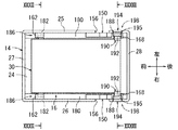
[実施形態12]図30は燃料タンクの要部を示す側断面図、図31はサブタンクに対するポンプユニットの組付け状態を示す平面図、図32は図31のXXXII−XXXII線矢視断面図、図33は図31のXXXIII−XXXIII線矢視断面図である。図30〜図33に示すように、本実施形態は、実施形態11(図26〜図29参照)におけるサブタンク14の底板部24の左右両側端部に、一段高くする段付部180が左右対称的に形成されている。両段付部180は、前後方向(図30において左右方向)に直線状に延在している。両段付部180上には、実施形態11(図26参照)におけるガイドレール150、係止片162、規制片168が同様に配置されている。 [Twelfth Embodiment] FIG. 30 is a side sectional view showing the main part of the fuel tank, FIG. 31 is a plan view showing the assembled state of the pump unit to the sub tank, and FIG. 32 is a sectional view taken along the line XXXII-XXXII in FIG. 33 is a cross-sectional view taken along line XXXIII-XXXIII in FIG. As shown in FIGS. 30 to 33, in the present embodiment, stepped portions 180 that are raised by one step are symmetrical in the left and right end portions of the bottom plate portion 24 of the sub tank 14 in the eleventh embodiment (see FIGS. 26 to 29). Is formed. Both stepped portions 180 extend linearly in the front-rear direction (left-right direction in FIG. 30). On both stepped portions 180, the guide rail 150, the locking piece 162, and the regulating piece 168 in the eleventh embodiment (see FIG. 26) are similarly arranged.

また、実施形態11(図26参照)のガイドピン160は前側のガイドピン(符号、182を付す)に変更され、ガイド片166は後側のガイドピン(符号、184を付す)に変更されている。前側のガイドピンは、マウント30の左右の両側面の前端部に配置されている。前側のガイドピン182は、例えば丸軸形状に形成されている。また、実施形態11(図26参照)のガイド片166は後側のガイドピン(符号、184を付す)に変更されている。後側のガイドピン184は、マウント30の左右の両側面の後端部に配置されている。後側のガイドピン184は、例えば丸軸形状に形成されている。また、係止片162を本明細書でいう「タンク本体側支持部」とし、前側のガイドピン182を本明細書でいう「ポンプユニット側支持部」として、相互に回動可能にかつ係脱可能に係合する回動支持手段186が構成されている(図30〜図32参照)。また、サブタンク14の底板部24の段付部180上において、両規制片168と両ガイドレール150との間には、係合溝(符号、188を付す)が形成されている(図30参照)。係合溝188には、後側のガイドピン184を上方から係合可能となっている。   In addition, the guide pin 160 of the eleventh embodiment (see FIG. 26) is changed to a front guide pin (reference numeral 182), and the guide piece 166 is changed to a rear guide pin (reference numeral 184). Yes. The front guide pins are disposed at the front end portions of the left and right side surfaces of the mount 30. The front guide pin 182 is formed in a round shaft shape, for example. Also, the guide piece 166 of the eleventh embodiment (see FIG. 26) is changed to a rear guide pin (reference numeral 184). The rear guide pins 184 are disposed at the rear ends of the left and right side surfaces of the mount 30. The rear guide pin 184 is formed in a round shaft shape, for example. Further, the locking piece 162 is a “tank body side support portion” as used in this specification, and the front guide pin 182 is a “pump unit side support portion” as used in this specification so as to be able to rotate with respect to each other. Rotating support means 186 that can be engaged is configured (see FIGS. 30 to 32). In addition, on the stepped portion 180 of the bottom plate portion 24 of the sub tank 14, an engagement groove (reference numeral 188) is formed between both the restricting pieces 168 and the both guide rails 150 (see FIG. 30). ). A rear guide pin 184 can be engaged with the engagement groove 188 from above.

図33に示すように、マウント30の後端部の左右両端部上には、例えばロック柱190が左右対称的に設けられている。ロック柱190の上端部には、外側方へ突出するフランジ部192が形成されている。一方、サブタンク14の左側板部25及び右側板部26の後端部上には、左右一対のロック片194が左右対称的に設けられている。ロック片194の上部には、内側方に突出するロック爪195が形成されている。ロック片194は、左右方向に弾性変形すなわち撓み変形可能に形成されている(図33中、二点鎖線194参照)。ロック爪195は、マウント30のロック柱190のフランジ部192に対してロック片197の弾性変形を利用して係合可能に形成されている。ロック柱190とロック片194とにより、ロック手段198が構成されている。   As shown in FIG. 33, for example, lock pillars 190 are provided symmetrically on the left and right ends of the rear end of the mount 30. A flange portion 192 that protrudes outward is formed at the upper end portion of the lock column 190. On the other hand, a pair of left and right lock pieces 194 are provided symmetrically on the rear end portions of the left side plate portion 25 and the right side plate portion 26 of the sub tank 14. A lock claw 195 protruding inward is formed on the top of the lock piece 194. The lock piece 194 is formed so as to be elastically deformable, that is, bendable in the left-right direction (see the two-dot chain line 194 in FIG. 33). The lock claw 195 is formed so as to be engageable with the flange portion 192 of the lock column 190 of the mount 30 by using elastic deformation of the lock piece 197. The lock column 190 and the lock piece 194 constitute a lock means 198.

なお、サブタンク14の段付部180は本明細書でいう「第3ガイド部材」に相当する。また、前側のガイドピン182は本明細書でいう「摺動子」、「先行側摺動子」、「ポンプユニット側支持部」に相当する。また、後側のガイドピン184は本明細書でいう「摺動子」、「後行側摺動子」に相当する。また、ロック柱190は本明細書でいう「ポンプユニット側ロック部」に相当する。また、ロック片194は本明細書でいう「タンク本体側ロック部」に相当する。   The stepped portion 180 of the sub tank 14 corresponds to a “third guide member” in this specification. Further, the front guide pin 182 corresponds to “slider”, “preceding side slider”, and “pump unit side support portion” in this specification. The rear guide pin 184 corresponds to a “slider” and a “rear slider” in this specification. Further, the lock column 190 corresponds to a “pump unit side lock portion” in this specification. The lock piece 194 corresponds to a “tank body side lock portion” in the present specification.

次に、タンク本体12に対するポンプユニット16の組付け方法について説明する。ポンプユニット16を、長手方向の一端部(前端部)を斜め前方へ傾かせた略垂直姿勢としてタンク本体12に挿入する。このとき、前側のガイドピン182を、サブタンク14のガイドレール150の前側の上流ガイド部152に係合させ、その前側の上流ガイド部152に沿って下方へ摺動させていく。続いて、前側のガイドピン182を、前側の上流ガイド部152から傾斜ガイド部153に摺動させる。この状態から、前側のガイドピン182を、タンク本体12の底面部21の段付部180に沿って前方へ移動させつつ、後側のガイドピン184をガイドレール150の後側のガイド面154に係合させ、そのガイド面154に沿って下方へ摺動させていく。すると、前側のガイドピン182がサブタンク14の係止片162に係合する。   Next, a method for assembling the pump unit 16 to the tank body 12 will be described. The pump unit 16 is inserted into the tank body 12 in a substantially vertical posture in which one end portion (front end portion) in the longitudinal direction is inclined obliquely forward. At this time, the front guide pin 182 is engaged with the upstream upstream guide portion 152 of the guide rail 150 of the sub tank 14 and is slid downward along the upstream upstream guide portion 152. Subsequently, the front guide pin 182 is slid from the front upstream guide portion 152 to the inclined guide portion 153. From this state, the front guide pin 182 is moved forward along the stepped portion 180 of the bottom surface portion 21 of the tank body 12, and the rear guide pin 184 is moved to the rear guide surface 154 of the guide rail 150. Engage and slide downward along the guide surface 154. Then, the front guide pin 182 engages with the locking piece 162 of the sub tank 14.

続いて、係止片162と前側のガイドピン182との係合による回動支持手段186を回動支点として、ポンプユニット16を下方へ回動させる。すなわち、ポンプユニット16の後端部を押し下げていく。そして、サブタンク14のロック片194のロック爪195にマウント30のロック柱190のフランジ部192が当接すると、ロック片194が外側方へ弾性変形(図33中、二点鎖線194参照)されていき、ロック柱190のフランジ部192がロック爪195を乗り越えると同時に、ロック凹部172が弾性復元し、ロック柱190のフランジ部192にロック爪195が係合いわゆるスナップフィット係合される(図33参照)。これと同時に、サブタンク14の係合溝188に後側のガイドピン184が係合する(図30参照)。これにより、タンク本体12にポンプユニット16がロックされる。   Subsequently, the pump unit 16 is rotated downward using the rotation support means 186 by the engagement between the locking piece 162 and the front guide pin 182 as a rotation fulcrum. That is, the rear end portion of the pump unit 16 is pushed down. When the flange portion 192 of the lock column 190 of the mount 30 comes into contact with the lock claw 195 of the lock piece 194 of the sub tank 14, the lock piece 194 is elastically deformed outward (see the two-dot chain line 194 in FIG. 33). As the flange 192 of the lock column 190 gets over the lock claw 195, the lock recess 172 is elastically restored, and the lock claw 195 is engaged with the flange 192 of the lock column 190, so-called snap-fit engagement (FIG. 33). reference). At the same time, the rear guide pin 184 engages with the engagement groove 188 of the sub tank 14 (see FIG. 30). As a result, the pump unit 16 is locked to the tank body 12.

また、ポンプユニット16を取外したい場合には、ロック片194の上端部を外側方へ押すことにより、ロック柱190のフランジ部192に対するロック爪195の係合を解除(図33中、二点鎖線194参照)した後、回動支持手段186を回動支点として、ポンプユニット16を上方へ回動させる。すなわち、ポンプユニット16の後端部を引き上げる。以降、挿入時とは逆順で、ポンプユニット16を取外せばよい。   When the pump unit 16 is to be removed, the lock claw 195 is disengaged from the flange portion 192 of the lock column 190 by pushing the upper end of the lock piece 194 outward (in FIG. 33, a two-dot chain line). 194), the pump unit 16 is rotated upward with the rotation support means 186 as a rotation fulcrum. That is, the rear end portion of the pump unit 16 is pulled up. Thereafter, the pump unit 16 may be removed in the reverse order of insertion.

前記した燃料タンク10によると、タンク本体12内にポンプユニット16を組付ける際に、ガイド手段のガイドレール150によって両ガイドピン110,112がガイドされる。これによって、ポンプユニット16がタンク本体12のタンクホール22側から底部側の組付け位置までガイドされる。したがって、ポンプユニット16を迷わずに容易に組付け位置へ適正に移動させることができる。このため、作業時間を短縮するとともに、ポンプユニット16の組付け不良を抑制することができる。よって、タンク本体12に対するポンプユニット16の組付け性を向上することができる。   According to the fuel tank 10 described above, when the pump unit 16 is assembled in the tank body 12, the guide pins 110 and 112 are guided by the guide rail 150 of the guide means. As a result, the pump unit 16 is guided from the tank hole 22 side of the tank body 12 to the assembly position on the bottom side. Therefore, the pump unit 16 can be easily moved appropriately to the assembly position without hesitation. For this reason, while shortening working time, the assembly | attachment defect of the pump unit 16 can be suppressed. Therefore, the assembling property of the pump unit 16 to the tank body 12 can be improved.

また、ポンプユニット16の長手方向の一端部を回動可能に支持する回動支持手段186が、タンク本体12側に設けられた係止片162(タンク本体側支持部)と、ポンプユニット16側に設けられかつ係止片162に係合される前側のガイドピン182(ポンプユニット側支持部)とにより構成されている。また、ガイドレール150には、前側の上流ガイド部152及び後側のガイド面154が設けられている。したがって、ガイドレール150の前側の上流ガイド部152及び後側のガイド面154により、ポンプユニット16の前側のガイドピン182及びガイド片166を上端部側から底部側にガイドすることができる。また、回動支持手段186の係止片162(タンク本体側支持部)と前側のガイドピン182(ポンプユニット側支持部)との係合により、ポンプユニット16の長手方向の一端部(前端部)を回動可能に支持することができる。よって、回動支持手段186を回動支点として、ポンプユニット16をタンク本体12の底部側の組付け位置に容易に回動させることができる。   Further, a rotation support means 186 that rotatably supports one end portion in the longitudinal direction of the pump unit 16 includes a locking piece 162 (tank body side support portion) provided on the tank body 12 side, and a pump unit 16 side. And a front guide pin 182 (pump unit side support portion) engaged with the locking piece 162. Further, the guide rail 150 is provided with a front upstream guide portion 152 and a rear guide surface 154. Therefore, the front guide pin 182 and the guide piece 166 of the pump unit 16 can be guided from the upper end side to the bottom side by the upstream upstream guide portion 152 and the rear guide surface 154 of the guide rail 150. In addition, one end portion (front end portion) of the pump unit 16 in the longitudinal direction is engaged by engagement between the locking piece 162 (tank body side support portion) of the rotation support means 186 and the front guide pin 182 (pump unit side support portion). ) Can be rotatably supported. Therefore, the pump unit 16 can be easily rotated to the assembly position on the bottom side of the tank body 12 with the rotation support means 186 as a rotation fulcrum.

また、タンク本体12とポンプユニット16との間には、回動支持手段186を回動支点としてポンプユニット16をタンク本体12の底部側の組付け位置に回動したときに、相互に係合するロック手段198が設けられている。ロック手段198は、タンク本体12側に設けられたロック片194と、ポンプユニット16側に設けられかつロック片194に係合されるロック柱190とを備えている。ロック片194とロック柱190とは、ロック片194の弾性変形を利用して係合可能に構成されている。したがって、ポンプユニット16をタンク本体12の底部側の組付け位置に回動したときには、ロック手段198のロック片194にロック柱190がロック片194の弾性変形を利用して係合することによって、タンク本体12にポンプユニット16がロックされる。また、ロック片194に対するロック柱190の係合をロック片194の弾性変形を利用して解除することによって、ポンプユニット16を挿入時とは逆順で取外すことができる。よって、ポンプユニット16をタンク本体12に着脱可能に組付けることができる。なお、ロック柱190を弾性変形可能に形成してもよい。   Further, the tank body 12 and the pump unit 16 are engaged with each other when the pump unit 16 is rotated to the assembly position on the bottom side of the tank body 12 with the rotation support means 186 as a rotation fulcrum. Locking means 198 is provided. The lock means 198 includes a lock piece 194 provided on the tank body 12 side and a lock column 190 provided on the pump unit 16 side and engaged with the lock piece 194. The lock piece 194 and the lock column 190 are configured to be engageable by utilizing elastic deformation of the lock piece 194. Therefore, when the pump unit 16 is rotated to the assembly position on the bottom side of the tank body 12, the lock pillar 190 is engaged with the lock piece 194 of the lock means 198 by utilizing elastic deformation of the lock piece 194, The pump unit 16 is locked to the tank body 12. Further, by releasing the engagement of the lock column 190 with the lock piece 194 using the elastic deformation of the lock piece 194, the pump unit 16 can be removed in the reverse order of insertion. Therefore, the pump unit 16 can be detachably assembled to the tank body 12. The lock column 190 may be formed to be elastically deformable.

また、サブタンク14の底板部24の段付部180によって、ポンプユニット16のマウント30の先端部(前端部)の前側のガイドピン182を回動支持手段186に向けてガイドすることができる。また、前側のガイドピン182は、回動支持手段186のポンプユニット側支持部を兼用するように構成されている。したがって、ポンプユニット側支持部として、特別な部材を設けなくて済む。   Further, the stepped portion 180 of the bottom plate portion 24 of the sub tank 14 can guide the guide pin 182 on the front side of the tip portion (front end portion) of the mount 30 of the pump unit 16 toward the rotation support means 186. Further, the front guide pin 182 is configured to also serve as the pump unit side support portion of the rotation support means 186. Therefore, it is not necessary to provide a special member as the pump unit side support portion.

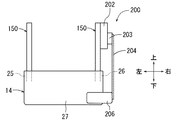
[実施形態13]図34は燃料タンクの要部を示す正面図、図35は同じく斜視図である。図34及び図35に示すように、本実施形態は、例えば、実施形態11(図26〜図30参照)の一方(例えば右側)のガイドレール150の上部の外側面に、センダゲージ200を設けたものである。センダゲージ200は、燃料残量検出装置で、ガイドレール150の上端部に装着されたゲージ本体202と、ゲージ本体202の回動部203に片持ち状に支持されたアーム204と、アーム204の自由端に取付けられたフロート206とにより構成されている。ゲージ本体202は、タンク本体12内の燃料残量に応じて上下するフロート206の位置すなわち回動部203の回動位置を燃料残量信号として出力する。 [Thirteenth Embodiment] FIG. 34 is a front view showing the main part of the fuel tank, and FIG. 35 is a perspective view of the same. As shown in FIGS. 34 and 35, in the present embodiment, for example, a sender gauge 200 is provided on the outer surface of the upper part of one (for example, the right side) guide rail 150 in the eleventh embodiment (see FIGS. 26 to 30). Is. The sender gauge 200 is a fuel remaining amount detection device. The gauge main body 202 attached to the upper end portion of the guide rail 150, the arm 204 supported in a cantilever manner by the rotating portion 203 of the gauge main body 202, and the arm 204 free And a float 206 attached to the end. The gauge body 202 outputs the position of the float 206 that moves up and down according to the fuel remaining amount in the tank body 12, that is, the rotation position of the rotation unit 203 as a fuel remaining amount signal.

なお、センダゲージ200のゲージ本体202は、ガイドレール150の上端部に限らず、ガイドレール150においてサブタンク14から露出した部分の任意の位置に装着してもよい。また、センダゲージ200のゲージ本体202は、ガイドレール150に代えて、実施形態7のガイドレール114(図21参照)に装着してもよい。また、センダゲージ200のゲージ本体202は、ガイドレール150に代えて、実施形態1のガイドレール55(図6参照)又は実施形態3のガイドレール84(図13参照)又はガイドレール104(図20参照)が設けられたサブタンク14の左側板部25の突出部25a又は右側板部26の突出部26aに装着してもよい。   The gauge body 202 of the sender gauge 200 is not limited to the upper end portion of the guide rail 150, and may be attached to any position of the guide rail 150 exposed from the sub tank 14. Further, the gauge body 202 of the sender gauge 200 may be attached to the guide rail 114 (see FIG. 21) of the seventh embodiment instead of the guide rail 150. Further, the gauge body 202 of the sender gauge 200 is replaced with the guide rail 150, the guide rail 55 (see FIG. 6) of the first embodiment, the guide rail 84 (see FIG. 13) of the third embodiment, or the guide rail 104 (see FIG. 20). ) May be mounted on the protruding portion 25a of the left side plate portion 25 of the sub tank 14 or the protruding portion 26a of the right side plate portion 26.

[他の実施形態]本発明は実施形態に限定されるものではなく、本発明の要旨を逸脱しない範囲における変更が可能である。例えば、本発明は、側面部に開口部を有するタンク本体を備える燃料タンクに適用してもよい。また、ポンプユニットに搭載される部品を増加してもよい。例えば、増加する部品としては、センダゲージ(燃料残量検出装置)の他、サブタンク外の燃料をタンク内へ移送するジェットポンプ、タンク本体内の圧力を検出する圧力センサ等が挙げられる。また、サブタンクは省略してもよい。また、ガイドレールの第3ガイド部及び第2ガイド部は省略してもよい。また、ポンプユニット16の両ガイド手段のうちの一方のガイド手段は省略してもよい。 [Other Embodiments] The present invention is not limited to the embodiments and can be modified without departing from the gist of the present invention. For example, the present invention may be applied to a fuel tank including a tank body having an opening on a side surface. Moreover, you may increase the components mounted in a pump unit. For example, the increasing parts include a sender gauge (remaining fuel amount detection device), a jet pump that transfers fuel outside the sub-tank into the tank, a pressure sensor that detects the pressure inside the tank body, and the like. Further, the sub tank may be omitted. Further, the third guide portion and the second guide portion of the guide rail may be omitted. Further, one guide means of both guide means of the pump unit 16 may be omitted.

10…燃料タンク
12…タンク本体
14…サブタンク
16…ポンプユニット
20…上面部
22…タンクホール(開口部)
24…底板部(第3ガイド部材)
27…前側板部(当接部材、タンク本体側支持部の一部)
30…マウント(ポンプ保持部材、摺動子側の部材)
32…燃料ポンプ
51…前側のガイドピン(摺動子、先行側摺動子、ポンプユニット側支持部)
53…後側のガイドピン(摺動子、後行側摺動子)
55…ガイドレール
60…第1ガイド部
62…第3ガイド部
62a…前端壁(タンク本体側支持部)
64…第2ガイド部
65…ロック溝部(ロック部、タンク本体側ロック部)
67…ロック手段
72…回動支持手段
74…サブタンク
78…ストッパピン(ストッパ部材、ポンプユニット側支持部)
79…ガイドピン(摺動子)
80…ストッパ片(係合部材、タンク本体側支持部の一部)
82…回動支持手段
84…ガイドレール
86…第2ガイド部
94…ロック手段
88…ロックバー(ポンプユニット側ロック部)
90…ロック部材(タンク本体側ロック部)
96…回動支持手段
98…係止凹部(タンク本体側支持部)
102…係止凸部(ポンプユニット側支持部)
104…ガイドレール
110…前側のガイドピン(摺動子、先行側摺動子、ポンプユニット側支持部)
112…後側のガイドピン(摺動子、後行側摺動子、ポンプユニット側ロック部)
114…ガイドレール
120…前側の上流ガイド部(第1ガイド部)
122…前側の下流ガイド部(第3ガイド部)
123…係止壁部(タンク本体側支持部)
126…後側の上流ガイド部(第1ガイド部)
128…後側の下流ガイド部(第2ガイド部)
130…ロック部(タンク本体側ロック部)
135…ロック手段
137…回動支持手段
140…サブタンク
144…後側のガイド面(第1ガイド部)
146…後側のガイドピン(摺動子、後行側摺動子、ポンプユニット側ロック部)
150…ガイドレール
152…前側の上流ガイド部(第1ガイド部)
154…後側のガイド面(第1ガイド部)
160…ガイドピン(摺動子、先行側摺動子、ポンプユニット側支持部)
162…係止片(タンク本体側支持部)
164…回動支持手段
166…ガイド片(摺動子、後行側摺動子)
172…ロック凹部(ポンプユニット側ロック部)
174…ロック片(タンク本体側ロック部)
178…ロック手段
180…段付部(第3ガイド部材)
182…前側のガイドピン(摺動子、先行側摺動子、ポンプユニット側支持部)
184…後側のガイドピン(摺動子、後行側摺動子)
186…回動支持手段
190…ロック柱(ポンプユニット側ロック部)
194…ロック片(タンク本体側ロック部)
198…ロック手段
DESCRIPTION OF SYMBOLS 10 ... Fuel tank 12 ... Tank main body 14 ... Sub tank 16 ... Pump unit 20 ... Upper surface part 22 ... Tank hole (opening part)
24 ... bottom plate (third guide member)
27: Front side plate part (contact member, part of tank body side support part)
30 ... Mount (pump holding member, slider side member)
32 ... Fuel pump 51 ... Front guide pin (slider, preceding slider, pump unit side support)
53 ... Rear guide pin (slider, trailing slider)
55 ... Guide rail 60 ... First guide part 62 ... Third guide part 62a ... Front end wall (tank body side support part)
64 ... 2nd guide part 65 ... Lock groove part (Lock part, tank main body side lock part)
67 ... Locking means 72 ... Turning support means 74 ... Sub tank 78 ... Stopper pin (stopper member, pump unit side support part)
79 ... Guide pin (slider)
80: Stopper piece (engaging member, part of tank body side support)
82 ... Turning support means 84 ... Guide rail 86 ... Second guide part 94 ... Locking means 88 ... Lock bar (pump unit side lock part)
90 ... Lock member (tank body side lock)
96 ... Turning support means 98 ... Locking recess (tank body side support)
102 ... Locking convex part (pump unit side support part)
104 ... guide rail 110 ... front guide pin (slider, leading slider, pump unit side support)
112 ... rear guide pin (slider, trailing slider, pump unit side lock)
114 ... guide rail 120 ... front upstream guide part (first guide part)
122: Front downstream guide portion (third guide portion)
123 ... Locking wall part (tank body side support part)
126... Upstream guide portion on the rear side (first guide portion)
128 ... downstream downstream guide portion (second guide portion)
130 ... Lock part (tank body side lock part)
135 ... Locking means 137 ... Rotating support means 140 ... Sub tank 144 ... Rear guide surface (first guide part)
146 ... Rear guide pin (slider, trailing slider, pump unit side lock)
150 ... guide rail 152 ... upstream upstream guide part (first guide part)
154: Rear guide surface (first guide part)
160 ... guide pin (slider, leading side slider, pump unit side support)
162 ... locking piece (tank body side support part)
164... Rotation support means 166... Guide piece (slider, trailing side slider)
172 ... Lock recess (pump unit side lock)
174 ... Lock piece (tank body side lock)
178 ... Locking means 180 ... Stepped portion (third guide member)
182 ... Front guide pin (slider, leading slider, pump unit side support)
184 ... Rear guide pin (slider, trailing slider)
186... Rotation support means 190... Lock pillar (pump unit side lock part)
194: Lock piece (tank body side lock)
198 ... Locking means

Claims (12)

開口部を有するタンク本体と、
燃料ポンプ、及び、燃料ポンプを保持するポンプ保持部材を有し、かつ、前記開口部から前記タンク本体の底部側に配置されるポンプユニットと、
を備える燃料タンクであって、
前記ポンプユニットを前記タンク本体の開口部側から底部側の組付け位置までガイドするガイド手段を備え、
前記ガイド手段は、前記タンク本体側に設けられるガイドレールと、前記ポンプユニット側に設けられかつ前記ガイドレールに摺動可能に係合される摺動子とにより構成されている燃料タンク。
A tank body having an opening;
A pump unit having a fuel pump and a pump holding member for holding the fuel pump, and disposed on the bottom side of the tank body from the opening;
A fuel tank comprising:
Guide means for guiding the pump unit from the opening side of the tank body to the assembly position on the bottom side,
The fuel tank includes a guide rail provided on the tank body side and a slider provided on the pump unit side and slidably engaged with the guide rail.
請求項1に記載の燃料タンクであって、
前記ガイド手段は、前記ポンプユニットの両側に配置されている燃料タンク。
The fuel tank according to claim 1,
The fuel tank is disposed on both sides of the pump unit.
請求項1又は2に記載の燃料タンクであって、
前記タンク本体の底部には、前記燃料ポンプに吸入される燃料を貯留するサブタンクが設けられ、
前記ガイドレールは、前記サブタンクの水平状態での燃料を貯留可能な高さ位置よりも上方へ延出されている燃料タンク。
The fuel tank according to claim 1 or 2,
At the bottom of the tank body, a sub tank for storing fuel sucked into the fuel pump is provided,
The said guide rail is the fuel tank extended upwards rather than the height position which can store the fuel in the horizontal state of the said sub tank.
請求項1又は2に記載の燃料タンクであって、
前記タンク本体内に挿入された前記ポンプユニットの長手方向の一端部を回動可能に支持する回動支持手段を備え、
前記回動支持手段は、前記タンク本体側に設けられたタンク本体側支持部と、前記ポンプユニット側に設けられかつ前記タンク本体側支持部に係合されるポンプユニット側支持部とにより構成され、
前記ガイドレールには、前記タンク本体の開口部側から底部側に延在する第1ガイド部が設けられている燃料タンク。
The fuel tank according to claim 1 or 2,
A rotation support means for rotatably supporting one end of the pump unit inserted in the tank body in the longitudinal direction;
The rotation support means includes a tank body side support portion provided on the tank body side and a pump unit side support portion provided on the pump unit side and engaged with the tank body side support portion. ,
The fuel tank, wherein the guide rail is provided with a first guide portion extending from the opening side to the bottom side of the tank body.
請求項4に記載の燃料タンクであって、
前記第1ガイド部の底部側端部に連続され、前記回動支持手段を回動支点として前記ポンプユニットを下方へ回動させる際に前記摺動子をガイドする第2ガイド部が設けられている燃料タンク。
The fuel tank according to claim 4,
A second guide portion is provided which is continuous with the bottom side end portion of the first guide portion and guides the slider when the pump unit is rotated downward with the rotation support means as a rotation fulcrum. Fuel tank.
請求項5に記載の燃料タンクであって、
前記ガイドレールの第2ガイド部の曲率半径は、下方に向かって次第に小さくなるように設定され、
前記摺動子側の部材は、前記摺動子が前記第2ガイド部を下方に摺動した際に弾性変形可能に形成され、
前記第2ガイド部には、前記ポンプユニットを前記タンク本体の底部側の組付け位置に回動したときに、前記摺動子側の部材の弾性復元により前記摺動子を係合するロック部が設けられている燃料タンク。
The fuel tank according to claim 5,
The radius of curvature of the second guide portion of the guide rail is set so as to gradually decrease downward,
The member on the slider side is formed to be elastically deformable when the slider slides down the second guide portion,
The second guide portion includes a lock portion that engages the slider by elastic restoration of a member on the slider side when the pump unit is rotated to the assembly position on the bottom side of the tank body. A fuel tank provided with
請求項4又は5に記載の燃料タンクであって、
前記タンク本体と前記ポンプユニットとの間には、前記回動支持手段を回動支点として前記ポンプユニットを前記タンク本体の底部側の組付け位置に回動したときに、相互に係合するロック手段が設けられ、
前記ロック手段は、前記タンク本体側に設けられたタンク本体側ロック部と、前記ポンプユニット側に設けられかつ前記タンク本体側ロック部に係合されるポンプユニット側ロック部とを備え、
前記タンク本体側ロック部と前記ポンプユニット側ロック部とは、少なくとも一方の弾性変形を利用して係合可能に構成されている燃料タンク。
The fuel tank according to claim 4 or 5, wherein
A lock between the tank body and the pump unit that engages with each other when the pump unit is rotated to the assembly position on the bottom side of the tank body with the rotation support means as a rotation fulcrum. Means are provided,
The locking means includes a tank body side lock portion provided on the tank body side, and a pump unit side lock portion provided on the pump unit side and engaged with the tank body side lock portion,
The tank main body side lock portion and the pump unit side lock portion are configured to be engageable by utilizing at least one elastic deformation.
請求項4〜7のいずれか1つに記載の燃料タンクであって、
前記ポンプユニットの長手方向の一端部に、先行側摺動子が設けられ、
前記ガイドレールには、前記第1ガイド部の底部側端部に連続され、前記先行側摺動子を前記タンク本体の底部に沿って所定位置までガイドする第3ガイド部が設けられている燃料タンク。
A fuel tank according to any one of claims 4 to 7,
A leading side slider is provided at one end of the pump unit in the longitudinal direction,
The guide rail is provided with a third guide portion that is continuous with the bottom side end portion of the first guide portion and guides the leading side slider to a predetermined position along the bottom portion of the tank body. tank.
請求項8に記載の燃料タンクであって、
前記先行側摺動子は、前記回動支持手段のポンプユニット側支持部を兼用するように構成されている燃料タンク。
The fuel tank according to claim 8, wherein
The preceding slider is a fuel tank configured to also serve as a pump unit side support portion of the rotation support means.
請求項4〜7のいずれか1つに記載の燃料タンクであって、
前記タンク本体の底部側には、前記ポンプユニットの長手方向の一端部を前記タンク本体の底部に沿ってガイドする第3ガイド部材が設けられている燃料タンク。
A fuel tank according to any one of claims 4 to 7,
A fuel tank provided on the bottom side of the tank body with a third guide member for guiding one end portion of the pump unit in the longitudinal direction along the bottom portion of the tank body.
請求項10に記載の燃料タンクであって、
前記ポンプユニットの長手方向の一端部には、ストッパ部材が設けられ、
前記タンク本体には、前記ポンプユニットの長手方向の一端部が当接する当接部材、及び、前記ストッパ部材を係合する係合部材が設けられ、
前記回動支持手段は、前記当接部材及び前記係合部材をタンク本体側支持部とし、前記ストッパ部材をポンプユニット側支持部として構成されている燃料タンク。
The fuel tank according to claim 10, wherein
A stopper member is provided at one end of the pump unit in the longitudinal direction,
The tank body is provided with an abutting member that abuts one end of the pump unit in the longitudinal direction, and an engaging member that engages the stopper member,
The rotation support means is a fuel tank configured such that the abutting member and the engaging member serve as a tank body side support portion, and the stopper member serves as a pump unit side support portion.
請求項10に記載の燃料タンクであって、
前記ポンプユニットの長手方向の一端部には、ポンプユニット側係止部が設けられ、
前記タンク本体には、前記ポンプユニット側係止部を係合するタンク本体側係止部が設けられ、
前記回動支持手段は、前記タンク本体側係止部をタンク本体側支持部とし、前記ポンプユニット側係止部をポンプユニット側支持部として構成されている燃料タンク。
The fuel tank according to claim 10, wherein
One end of the pump unit in the longitudinal direction is provided with a pump unit side locking portion,
The tank body is provided with a tank body side locking portion for engaging the pump unit side locking portion,
The said rotation support means is a fuel tank comprised as the said tank main body side latching | locking part made into the tank main body side support part, and the said pump unit side latching | locking part as a pump unit side support part.
JP2015123136A 2015-06-18 2015-06-18 Fuel tank Pending JP2017008761A (en)

Priority Applications (2)

Application Number Priority Date Filing Date Title
JP2015123136A JP2017008761A (en) 2015-06-18 2015-06-18 Fuel tank
US15/185,342 US9752543B2 (en) 2015-06-18 2016-06-17 Fuel tank

Applications Claiming Priority (1)

Application Number Priority Date Filing Date Title
JP2015123136A JP2017008761A (en) 2015-06-18 2015-06-18 Fuel tank

Publications (1)

Publication Number Publication Date
JP2017008761A true JP2017008761A (en) 2017-01-12

Family

ID=57587779

Family Applications (1)

Application Number Title Priority Date Filing Date
JP2015123136A Pending JP2017008761A (en) 2015-06-18 2015-06-18 Fuel tank

Country Status (2)

Country Link
US (1) US9752543B2 (en)
JP (1) JP2017008761A (en)

Cited By (1)

* Cited by examiner, † Cited by third party
Publication number Priority date Publication date Assignee Title
JP2018122684A (en) * 2017-01-31 2018-08-09 株式会社Fts Fuel tank

Families Citing this family (9)

* Cited by examiner, † Cited by third party
Publication number Priority date Publication date Assignee Title
JP6258158B2 (en) * 2014-08-26 2018-01-10 愛三工業株式会社 Fuel supply device
JP6599248B2 (en) * 2016-01-21 2019-10-30 愛三工業株式会社 Fuel supply device
JP6388001B2 (en) * 2016-04-20 2018-09-12 株式会社デンソー Fuel supply device
JP6662757B2 (en) * 2016-11-18 2020-03-11 株式会社デンソー Fuel supply device and method of attaching and detaching fuel supply device
JP2018159333A (en) * 2017-03-23 2018-10-11 株式会社デンソー Fuel tank and fuel supply system using the same
EP3505772B1 (en) * 2017-12-29 2021-04-07 TI Automotive Technology Center GmbH Sucking jet pump arrangement
JP7271383B2 (en) * 2019-09-30 2023-05-11 愛三工業株式会社 FUEL PUMP MODULE, FUEL SUPPLY DEVICE, AND METHOD OF INSTALLING FUEL PUMP MODULE ON FUEL TANK
KR20220081726A (en) * 2020-12-09 2022-06-16 현대자동차주식회사 Fuel pump module
KR20230028825A (en) * 2021-08-23 2023-03-03 현대자동차주식회사 Fuel pump module for vehicle

Family Cites Families (7)

* Cited by examiner, † Cited by third party
Publication number Priority date Publication date Assignee Title
JPH068294Y2 (en) 1987-07-09 1994-03-02 日産自動車株式会社 Fuel tank structure
US6014957A (en) * 1996-11-27 2000-01-18 Siemens Automotive Corp. Fuel pump module for the fuel tank of an automotive vehicle
FR2776967B1 (en) * 1998-04-02 2000-05-12 Bitron France FUEL PUMP ASSEMBLY AND MOTOR VEHICLE TANK EQUIPPED WITH SUCH AN ASSEMBLY
JP4217464B2 (en) 2001-11-30 2009-02-04 ティーアイ グループ オートモーティヴ システムズ リミテッド ライアビリティー カンパニー Fuel tank assembly
US7341047B2 (en) * 2006-08-10 2008-03-11 Nissan Technical Center North America, Inc. Vehicle fuel tank assembly
JP2008174074A (en) 2007-01-18 2008-07-31 Fts:Kk Fuel tank
JP2008190429A (en) * 2007-02-05 2008-08-21 Denso Corp Fuel pump module

Cited By (1)

* Cited by examiner, † Cited by third party
Publication number Priority date Publication date Assignee Title
JP2018122684A (en) * 2017-01-31 2018-08-09 株式会社Fts Fuel tank

Also Published As

Publication number Publication date
US9752543B2 (en) 2017-09-05
US20160369756A1 (en) 2016-12-22

Similar Documents

Publication Publication Date Title
JP2017008761A (en) Fuel tank
JP6162183B2 (en) Fuel supply device
JP4320134B2 (en) Fuel supply unit
US11174824B2 (en) Cover for fuel tank
US11619199B2 (en) Cover for fuel tank
US11118549B2 (en) Cover for fuel tank
JP6177152B2 (en) Filler pipe
US8402643B2 (en) Gas cartridge loading mechanism
JP2011117376A (en) Filtering device
CN102729958B (en) The washing equipment of lamps apparatus for vehicle and nozzle casing
JPWO2017141628A1 (en) Fuel supply device
JP2008265621A (en) Oil filler port structure of filler pipe
JP5367465B2 (en) Flap valve device
JP5888795B2 (en) Filler pipe
JP2008254634A (en) Vehicular fuel supply device
JP2018087459A (en) Private part washing unit
JP2016211505A (en) Fuel tank
JP2016164387A (en) Fuel tank
US8881765B2 (en) Fuel feed apparatus
JP5210213B2 (en) Cleaning device for vehicle lamp
JP2016160918A (en) Fuel tank
JP2015150924A (en) fuel tank
JP6097078B2 (en) Nozzle device for lamp cleaner device and method for assembling nozzle device for lamp cleaner device
JP2016186246A (en) Fuel tank
JP4096361B2 (en) Pressure regulator and fuel supply device using the same