JP4309110B2 - Adaptive antenna wireless communication device - Google Patents
Adaptive antenna wireless communication device Download PDFInfo
- Publication number
- JP4309110B2 JP4309110B2 JP2002283194A JP2002283194A JP4309110B2 JP 4309110 B2 JP4309110 B2 JP 4309110B2 JP 2002283194 A JP2002283194 A JP 2002283194A JP 2002283194 A JP2002283194 A JP 2002283194A JP 4309110 B2 JP4309110 B2 JP 4309110B2
- Authority
- JP
- Japan
- Prior art keywords
- subcarrier
- band
- transmission
- unit
- divided
- Prior art date
- Legal status (The legal status is an assumption and is not a legal conclusion. Google has not performed a legal analysis and makes no representation as to the accuracy of the status listed.)
- Expired - Lifetime
Links
Images
Classifications
-
- G—PHYSICS
- G01—MEASURING; TESTING
- G01S—RADIO DIRECTION-FINDING; RADIO NAVIGATION; DETERMINING DISTANCE OR VELOCITY BY USE OF RADIO WAVES; LOCATING OR PRESENCE-DETECTING BY USE OF THE REFLECTION OR RERADIATION OF RADIO WAVES; ANALOGOUS ARRANGEMENTS USING OTHER WAVES
- G01S3/00—Direction-finders for determining the direction from which infrasonic, sonic, ultrasonic, or electromagnetic waves, or particle emission, not having a directional significance, are being received
- G01S3/02—Direction-finders for determining the direction from which infrasonic, sonic, ultrasonic, or electromagnetic waves, or particle emission, not having a directional significance, are being received using radio waves
- G01S3/04—Details
- G01S3/043—Receivers
-
- H—ELECTRICITY
- H04—ELECTRIC COMMUNICATION TECHNIQUE
- H04B—TRANSMISSION
- H04B7/00—Radio transmission systems, i.e. using radiation field
- H04B7/02—Diversity systems; Multi-antenna system, i.e. transmission or reception using multiple antennas
- H04B7/04—Diversity systems; Multi-antenna system, i.e. transmission or reception using multiple antennas using two or more spaced independent antennas
- H04B7/08—Diversity systems; Multi-antenna system, i.e. transmission or reception using multiple antennas using two or more spaced independent antennas at the receiving station
- H04B7/0837—Diversity systems; Multi-antenna system, i.e. transmission or reception using multiple antennas using two or more spaced independent antennas at the receiving station using pre-detection combining
- H04B7/0842—Weighted combining
- H04B7/086—Weighted combining using weights depending on external parameters, e.g. direction of arrival [DOA], predetermined weights or beamforming
-
- G—PHYSICS
- G01—MEASURING; TESTING
- G01S—RADIO DIRECTION-FINDING; RADIO NAVIGATION; DETERMINING DISTANCE OR VELOCITY BY USE OF RADIO WAVES; LOCATING OR PRESENCE-DETECTING BY USE OF THE REFLECTION OR RERADIATION OF RADIO WAVES; ANALOGOUS ARRANGEMENTS USING OTHER WAVES
- G01S3/00—Direction-finders for determining the direction from which infrasonic, sonic, ultrasonic, or electromagnetic waves, or particle emission, not having a directional significance, are being received
- G01S3/02—Direction-finders for determining the direction from which infrasonic, sonic, ultrasonic, or electromagnetic waves, or particle emission, not having a directional significance, are being received using radio waves
- G01S3/14—Systems for determining direction or deviation from predetermined direction
-
- H—ELECTRICITY
- H04—ELECTRIC COMMUNICATION TECHNIQUE
- H04L—TRANSMISSION OF DIGITAL INFORMATION, e.g. TELEGRAPHIC COMMUNICATION
- H04L27/00—Modulated-carrier systems
- H04L27/26—Systems using multi-frequency codes
- H04L27/2601—Multicarrier modulation systems
Landscapes
- Engineering & Computer Science (AREA)
- Physics & Mathematics (AREA)
- General Physics & Mathematics (AREA)
- Radar, Positioning & Navigation (AREA)
- Remote Sensing (AREA)
- Computer Networks & Wireless Communication (AREA)
- Signal Processing (AREA)
- Radio Transmission System (AREA)
- Variable-Direction Aerials And Aerial Arrays (AREA)
- Mobile Radio Communication Systems (AREA)
Abstract
Description
【0001】
【発明の属する技術分野】
本発明は、周波数の異なる複数のサブキャリアを用いたマルチキャリア伝送方式のディジタル無線通信システムにおいて、到来パスの方向推定手段と、それに基づく指向性制御手段を有するアレーアンテナ備えた適応アンテナ無線通信装置に関する。
【0002】
【従来の技術】
無線通信装置が受信する信号は、様々な信号による干渉を受けて、受信品質の劣化が生ずる。この干渉を抑制し、所望方向から到来する信号のみを強く受信する技術として、アダプティブアレーアンテナ(適応アンテナ)が知られている。アダプティブアレーアンテナでは、受信信号に乗算する重み付け係数(以下、この重み付け係数を「重み」という。)を調整して受信信号に対して与える振幅と位相を調整することにより、所望方向から到来する信号のみを強く受信することができる。
【0003】
また、近年、無線通信の大容量化と、高速化への要求が高まりをみせており、その実現には耐マルチパス性や耐フェージング対策が大きな課題となっている。広帯域伝送を行う帯域内を複数の狭帯域なサブキャリアにより並列的に伝送するマルチキャリア伝送は、課題解決のための一つのアプローチであり、特に直交周波数分割多重(OFDM)伝送方式は地上波ディジタル放送や広帯域無線アクセスシステムにおいて採用されている。
【0004】
マルチキャリア伝送システムにおいて、アダプティブアレーアンテナを用いることで、両者の特徴をさらに生かすことが可能であり、耐マルチパス性、耐フェージング性をさらに高めることができる。
【0005】
詳細構成についての説明は省略するが、マルチキャリア伝送システムにおいて、アダプティブアレーアンテナを備えた従来の無線装置として、サブキャリア毎にアンテナ重みを演算することで、比帯域(=使用する全通信帯域/全通信帯域の中心周波数)が大きい場合でも、OFDM伝送方式の全通信帯域に均一なアンテナ指向性ビームが得られ、全通信帯域内でマルチパス等の妨害波の影響を受けにくい送受信を可能にしているという開示例がある(例えば、特許文献1参照)。
【0006】
【特許文献1】
特開平11−205026号公報
【0007】
【発明が解決しようとする課題】
しかしながら、従来の適応アンテナ無線通信装置においては、サブキャリア毎に方向推定を行い、アレー重みを演算するため、周波数選択性フェージングの影響をうける場合、受信電力が小さいサブキャリア信号に対しては十分な精度で方向推定が行えないという課題が生じる。また、サブキャリア数が多い場合にはサブキャリア毎に方向推定する場合には回路規模が増大するといった課題を有していた。
【0008】
本発明は、広帯域なマルチキャリア伝送方式を行う場合において、隣接するサブキャリア信号間での空間的なスペクトラムの相関が高いことを利用し、通信帯域内を分割した分割帯域内に属するサブキャリア信号群の平均的な到来方向を推定することで、受信電力が小さいサブキャリアが存在する場合でも、それが属するサブキャリア信号群としての到来方向を推定することで、推定精度の劣化を抑えることを可能にしている。また、サブキャリア信号毎の複数パスの個別あるいは平均的な方向推定も可能とする。
【0009】
指向性送信する場合、分割帯域毎あるいは全通信帯域での空間的なスペクトラムをもとに角度広がりを検出することで、角度広がりが小さい場合は、全サブキャリア信号群の平均的な到来方向に基づき送信指向性制御を行い、角度広がりが大きい場合は、1)分割帯域毎の方向推定結果のなかで最大受信電力を与える方向に指向性送信制御、または、2)分割帯域毎の方向推定結果の中で所定数の上位受信電力を与える方向に指向性送信制御を行う。これにより受信時の到来パス方向に指向性送信が可能となり、他ユーザへの干渉を効果的に低減することができ、通信品質を高め、システム容量を改善することができる。
【0010】
【課題を解決するための手段】
本発明の適応アンテナ無線通信装置は、マルチキャリア伝送された高周波信号を受信する複数のアンテナ素子で構成されるアレーアンテナと、前記アンテナ素子毎に受信された高周波信号を複数のサブキャリア信号に分波する分波器と、前記マルチキャリア伝送される全通信帯域をNd個(ただし、Ndは2以上、かつ、マルチキャリア伝送に用いられるサブキャリア数以下の自然数)に分割し、各分割帯域に属するサブキャリア信号群を用いて電波の到来方向推定を行うNd個の分割帯域方向推定部と、前記分割帯域毎に前記分割帯域方向推定部の推定方向に指向性ビームを有するアレー重みを生成する分割帯域アレー重み生成部と、前記分割帯域毎に生成された前記アレー重みを対応する前記分割帯域内に属するそれぞれのサブキャリア信号に乗算合成することで指向性形成するサブキャリア指向性形成部と、前記サブキャリア指向性形成部の出力を用いてデータ復調する復調部とを具備する構成を採る。
【0011】
【発明の実施の形態】
本発明の請求項1に記載の発明は、マルチキャリア伝送された高周波信号を受信する複数のアンテナ素子で構成されるアレーアンテナと、前記アンテナ素子毎に受信された高周波信号を複数のサブキャリア信号に分波する分波器と、前記マルチキャリア伝送される全通信帯域をNd個(ただし、Ndは2以上、かつ、マルチキャリア伝送に用いられるサブキャリア数以下の自然数)に分割し、各分割帯域に属するサブキャリア信号群を用いて電波の到来方向推定を行うNd個の分割帯域方向推定部と、前記分割帯域毎に前記分割帯域方向推定部の推定方向に指向性ビームを有するアレー重みを生成する分割帯域アレー重み生成部と、前記分割帯域毎に生成された前記アレー重みを対応する前記分割帯域内に属するそれぞれのサブキャリア信号に乗算合成することで指向性形成するサブキャリア指向性形成部と、前記サブキャリア指向性形成部の出力を用いてデータ復調する復調部とを具備することを特徴とし、分割された帯域内のサブキャリア信号群の到来方向推定が可能であり、方向推定結果に基づいた指向性受信ができるという作用を有する。
【0012】
本発明の請求項2に記載の発明は、分割帯域方向推定部は、サブキャリア信号に埋め込まれた既知のパイロット信号を用いて、入力された各サブキャリア信号とのパイロット信号相関値を算出し、異なるアンテナ素子で受信されたサブキャリア信号間で算出された前記パイロット信号相関値の相関値を基に到来方向推定を行うことを特徴とし、パイロット相関値の位相を基準とした方向推定ができるという作用を有する。
【0013】
本発明の請求項3に記載の発明は、分割帯域方向推定部は、サブキャリア信号群に属するサブキャリア数がL個で、列ベクトルVkの第m番目の要素を、第k番目のサブキャリア信号における第m番目のアンテナ素子でのパイロット信号相関値とし、Hを複素共役転置演算子とした場合、R=V1V1 H+V2V2 H+・・・+VLVL Hとして表せる相関行列Rを用いて到来方向推定を行うことを特徴とし、サブキャリア信号群の到来方向を平均した方向を精度よく検出できるという作用を有する。
【0014】
本発明の請求項4に記載の発明は、分割帯域方向推定部は、サブキャリア信号群に属するサブキャリア数がL個で、その第k番目のサブキャリア信号における第m番目のアンテナ素子でのパイロット信号相関値を第m番目の要素にもつ列ベクトルをVk、Vkxを列ベクトルVkの第x番目の要素(ただし、xはアンテナ素子数以下の自然数)とし、*を複素共役転置演算子とした場合、z=V1x *V1+V2x *V2+・・・+VLx *VNとして表せる相関ベクトルzを用いて到来方向推定を行うことを特徴とし、サブキャリア信号群の到来方向を平均した方向を精度よく検出できるという作用を有する。
【0015】
本発明の請求項5に記載の発明は、分割帯域方向推定部は、サブキャリア信号に埋め込まれた既知のパイロット信号を用いて、入力された各サブキャリア信号との相互相関演算を行うことで遅延プロファイルを算出し、前記遅延プロファイルから複数のパス到来タイミングを検出し、前記到来パスタイミング毎に、異なるアンテナ素子で受信されたサブキャリア信号間で算出された前記パイロット信号相関値の相関値を基に到来方向推定を行うことを特徴とし、サブキャリア信号毎に含まれるマルチパス波の到来方向を推定できるという作用を有する。
【0016】
本発明の請求項6に記載の発明は、分割帯域方向推定部は、サブキャリア信号群に属するサブキャリア数がL個で、その第k番目のサブキャリア信号における第p番目の到来パス(全到来パス数はS)の第m番目のアンテナ素子でのパイロット信号相関値をm番目の要素にもつ列ベクトルをVk(p)、Hを複素共役転置演算子とした場合、
【数3】

【0017】
本発明の請求項7に記載の発明は、分割帯域方向推定部は、サブキャリア信号群に属するサブキャリア数がL個で、その第k番目のサブキャリア信号における第p番目の到来パス(全到来パス数はS)の第m番目のアンテナ素子でのパイロット信号相関値をm番目の要素にもつ列ベクトルをVk(p)、Vkx(p)を列ベクトルVk(p)のx番目の要素(ただし、xはアンテナ素子数以下の自然数)とし、*を複素共役転置演算子とした場合、
【数4】
【0018】
本発明の請求項8に記載の発明は、分割帯域方向推定部は、相関行列Rを用いて、MUSIC法、ESPRIT法、CAPON法、あるいはフーリエ法のいずれかの手法を用いて到来方向推定を行うことを特徴とし、様々な到来方向推定手法を適用することができるという作用を有する。
【0019】
本発明の請求項9に記載の発明は、分割帯域方向推定部は、相関行列Rに空間スムージング処理を適用後に、MUSIC法、ESPRIT法、CAPON法、あるいはフーリエ法のいずれかの手法を用いて到来方向推定を行うことを特徴とし、相関波が存在する場合でも推定精度を確保できるという作用を有する。
【0020】
本発明の請求項10に記載の発明は、分割帯域方向推定部は、相関行列Rにユニタリ変換処理を適用後に、MUSIC法、ESPRIT法、CAPON法、あるいはフーリエ法のいずれかの手法を用いて到来方向推定することを特徴とし、アレーアンテナが等間隔直線アレーの場合、方向ベクトルを実数化することができるため、演算処理量を低減できるという作用を有する。
【0021】
本発明の請求項11に記載の発明は、全通信帯域でのサブキャリア信号を用いて到来方向推定を行う全帯域方向推定部と、Nd個の分割帯域方向推定部での方向推定結果の偏差が所定値以下の場合、前記全帯域方向推定部の推定値を選択して出力し、偏差が所定値より大きい場合、前記分割帯域方向推定部の推定値を出力する方向推定結果選択部と、前記方向推定結果選択部の出力を用いてアレー重みを生成する分割帯域アレー生成部とを具備することを特徴とし、帯域内での到来方向の分散から適応的に指向性制御方法を切り替えることができるという作用を有する。
【0022】
本発明の請求項12に記載の発明は、全通信帯域でのサブキャリア信号を用いて到来方向推定を行う全帯域方向推定部と、前記全帯域方向推定部で算出される空間プロファイルから角度広がりを検出し、角度広がりが所定値以下の場合、前記全帯域方向推定部の推定値を選択して出力し、角度広がりが所定値より大きい場合、前記分割帯域方向推定部の推定値を出力する方向推定結果選択部と、前記方向推定結果選択部の出力を用いてアレー重みを生成する分割帯域アレー生成部とを具備することを特徴とし、帯域内での到来方向の広がりから適応的に指向性制御方法を切り替えることができるという作用を有する。
【0023】
本発明の請求項13に記載の発明は、時間分割デュプレックス(TDD)方式または周波数分割デュプレックス(FDD)方式でマルチキャリア伝送される無線システムにおいて、方向推定結果選択部で選択された推定方向結果を基に分割帯域毎に1つの送信指向性ビームを形成する送信アレー重みを算出するサブキャリア送信重み生成部と、前記分割帯域毎に前記送信アレー重みを送信サブキャリア信号に乗算することで指向性ビーム送信するサブキャリア送信指向性形成部とを具備することを特徴とし、帯域内での到来方向の広がりから適応的に指向性制御方法を切り替えることができるという作用を有する。
【0024】
本発明の請求項14に記載の発明は、時間分割デュプレックス(TDD)方式でマルチキャリア伝送される無線システムにおいて、分割帯域毎の分割帯域アレー重み生成部で生成されたアレー重みを送信アレー重みとして用いるサブキャリア送信重み生成部と、前記分割帯域毎に共通な送信アレー重みを用いて指向性ビームを送信するサブキャリア送信指向性形成部とを具備することを特徴とし、分割帯域毎に受信指向性と同じ指向性を用いて送信ができるという作用を有する。
【0025】
本発明の請求項15に記載の発明は、時間分割デュプレックス(TDD)方式または周波数分割デュプレックス(FDD)方式でマルチキャリア伝送される無線システムにおいて、分割帯域毎の分割帯域方向推定部での推定方向結果から、前記分割帯域のうち最大受信電力与える推定方向に送信指向性ビームを形成する送信アレー重みを算出するサブキャリア送信重み生成部と、前記送信アレー重みを用いて全分割帯域で共通の指向性ビームを送信するサブキャリア送信指向性形成部とを具備することを特徴とし、分割帯域の中で最大受信電力を与えるパス方向に送信ビームを形成できるという作用を有する。
【0026】
本発明の請求項16に記載の発明は、時間分割デュプレックス(TDD)方式または周波数分割デュプレックス(FDD)方式でマルチキャリア伝送される無線システムにおいて、分割帯域毎の分割帯域方向推定部での推定方向結果から推定方向の偏差を算出し、偏差が所定値以下の場合には前記分割帯域方向推定部で得られるすべての方向推定値の平均方向に、所定値より大きい場合には前記分割帯域から所定数の受信電力上位を与える推定方向にマルチビームとなる送信指向性ビームを形成する送信アレー重みを算出するサブキャリア送信重み生成部を具備することを特徴とし、帯域内での到来方向の広がりから適応的に指向性制御方法を切り替えることができるという作用を有する。
【0027】
本発明の請求項17に記載の発明は、サブキャリア伝送は、直交周波数分割多重(OFDM)されたサブキャリア信号である請求項1から17記載のいずれかの適応アンテナ無線通信装置であること特徴とし、周波数使用効率の高い変調方式で伝送できるという作用を有する。
【0028】
本発明の請求項18に記載の発明は、サブキャリア伝送は、周波数軸方向に符号拡散多重することでユーザ多重されたサブキャリア信号であることを特徴とする請求項1から17記載のいずれかの適応アンテナ無線通信装置であることを特徴とし、符号拡散多重によりユーザ多重ができるシステムに適用できる作用を有する。
【0029】
本発明の請求項19に記載の発明は、サブキャリア伝送は、時間軸方向に符号拡散多重することでユーザ多重されたサブキャリア信号であることを特徴とする請求項1から17記載のいずれかの適応アンテナ無線通信装置である特徴とし、符号拡散多重によりユーザ多重ができるシステムに適用できる作用を有する。
【0030】
本発明の請求項20に記載の発明は、符号拡散多重によりユーザ多重されたサブキャリア信号を用いたサブキャリア伝送の場合、多重されたユーザ毎に送信アレー重みあるいは受信アレー重みを生成し、指向性受信を行うことを特徴とする請求項18から19記載のいずれかの適応アンテナ無線通信装置であることを特徴とし、多重ユーザ毎に分割帯域毎に最適な指向性制御が可能となる作用を有する。
【0031】
本発明の請求項21に記載の発明は、分割帯域アレー重み生成部は、対応する分割帯域での分割帯域方向推定部の方向推定結果に指向性ビームを有し、多重されている他ユーザの推定方向にはヌルを形成するアレー重みを生成することを特徴とする請求項20記載の適応アンテナ無線通信装置であること特徴とし、多重ユーザ毎に分割帯域毎に干渉方向にヌルを形成した最適な指向性受信が可能となる作用を有する。
【0032】
本発明の請求項22に記載の発明は、サブキャリア送信重み生成部は、所望ユーザ方向に指向性ビームを有し、多重されている他ユーザ方向にはヌルを形成する送信分割帯域アレー重みを生成することを特徴とする請求項20記載の適応アンテナ無線通信装置であること特徴とし、多重ユーザ毎に分割帯域毎に干渉方向にヌルを形成した最適な指向性送信受信が可能となる作用を有する。
【0033】
以下、本発明の実施の形態について、図1から図7を用いて説明する。
【0034】
(実施の形態1)
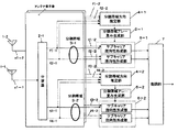
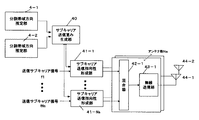
図1は、本発明の実施の形態1に係る適応アンテナ無線通信装置の構成を示すブロック図である。図1に示す適応アンテナ無線通信装置は、複数Na個のアンテナ素子1−1〜Naから構成されるアレーアンテナ1、第k番目のアンテナ素子1−kで受信された高周波信号s1−kを周波数変換後に、複数Ns個のサブキャリア信号f1−kからfNs−kに分波する分波器2―k(ただし、k=1〜Na)、通信帯域をNd個に分割した分割帯域のうち、第m番目の分割帯域3−mに属するサブキャリア信号群を用いて到来方向推定を行う分割帯域方向推定部4−m、第m番目の分割帯域方向推定部4−mでの方向推定結果を基にアレー重みを生成する分割帯域アレー重み生成部5−m、分割帯域アレー重み生成部5−mによるアレー重みを用いて、第m番目の分割帯域3−mに属するサブキャリア信号群に対し指向性形成するサブキャリア指向性形成部6−m、指向性受信された各サブキャリア信号を用いてデータ復調を行う復調部7から構成されている。ただし、m=1、...、Ndである。なお、図1ではアンテナ素子数Na=2、サブキャリア数Ns=4、分割帯域数Nd=2の場合の構成例を示している。
【0035】
以下、図1を用いてその動作の説明を行う。まず、アレーアンテナ1を構成するアンテナ素子1−1〜Naにてマルチキャリア方式で伝送された高周波信号s1−1〜Naをそれぞれ受信する。このうち第k番目のアンテナ素子1−kにより受信された高周波信号s1−kは、分波器2−kにより、高周波増幅、周波数変換を順次施されマルチキャリア伝送に用いられる複数Ns個のサブキャリア信号f1―k、f2−k、...、fNs―kが抽出される。ここで、全通信帯域をNd個の分割帯域に分け、その内の第m番目の分割帯域3−mに属するサブキャリア信号群は、分割帯域方向推定部4−mとサブキャリア指向性形成部6−mにそれぞれ入力される。なお、分割帯域数Ndは、全サブキャリア数Ns≧Nd>1の範囲にある自然数で設定することができる。また、各分割帯域3に属するサブキャリア信号群に属するサブキャリア数は必ずしも等しい必要はないが、以下では、等しいサブキャリア数Nc(=Ns/Nd)が属するものとして説明を行う。
【0036】
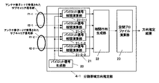
第m番目の分割帯域3−mに属するサブキャリア信号群を用いて分割帯域方向推定部4―mは到来方向推定を行う。図2は分割帯域方向推定部4の詳細な構成図を示す。図2において、分割帯域方向推定部4は、各サブキャリア信号に埋め込まれた予め既知であるパイロット信号を生成するパイロット信号生成部20、受信された各サブキャリア信号と生成されたパイロット信号との相関値を演算するパイロット信号相関演算部21、パイロット信号相関値を基に相関行列を生成する相関行列生成部22、相関行列を基に空間プロファイルを演算する空間プロファイル演算部23とから構成されている。以下、図2を用いてその動作説明を行う。なお、図2はアンテナ素子数Na=2、分割帯域内のサブキャリア数Nc=2の場合における第1番目の分割帯域3−1における分割帯域方向推定部4―1の例を示す。
【0037】
パイロット信号生成部20はサブキャリア信号にあらかじめ埋め込まれた既知信号(以下パイロット信号)を生成する。パイロット信号相関演算部21は生成されたパイロット信号と、サブキャリア信号の受信パイロットシンボルとの相関演算を行う。ここで、パイロット信号をr(s)とする。ただし、s=1〜Npであり、Npはパイロット信号のシンボル数とする。第k番目のアンテナ素子1−kで受信された第m番目の分割帯域3−mに属する第n番目のサブキャリア信号fn−k(t0)(なお、t0はパス到来タイミングを表す。)に対し、パイロット信号相関演算部21―n―kは、(数5)に示す相関演算を行い、パイロット相関値hnkを算出する。ただし、Noはシンボルに対するオーバーサンプル数、*は複素共役を示す。以下、すべてのアンテナ素子(k=1〜Na)で受信された第m番目の分割帯域3−mに属するサブキャリア信号群(n=1〜Nc)に対しパイロット相関値hnkを算出する。
【0038】
【数5】
【0039】
【数6】
【数7】
【0041】
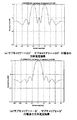
空間プロファイル演算部23は、(数8)に示す到来方向推定評価関数F(θ)におけるパラメータθを所定の角度ステップΔθで可変することで空間プロファイルを算出し、空間プロファイルのピークレベルの高い順に所定数M(M≧1)のピーク方向を検出し、到来方向推定値とする。ただし、a(θ)はアレーアンテナ1の素子配置で決まる方向ベクトルであり、例えば素子間隔dの等間隔直線アレーの場合、(数9)のように表すことができる。ここで、λは搬送波帯での分割帯域3−mにおける中心周波数の波長であり、θは直線アレーの法線方向を0°方向としている。また、Hは複素共役転置を表す。
【0042】
【数8】
【数9】
【0044】
分割帯域アレー重み生成部5−mは、第m番目の分割帯域3−mに属するサブキャリア信号群に対し、分割帯域方向推定部4−mでの方向推定結果の最大ピーク方向または所定数の複数ピーク方向に主ビームを向けるアレー重みを生成し、サブキャリア指向性形成部6−mは、生成されたアレー重みを各サブキャリア信号に対し共通に乗算合成した信号を出力する。なお、アレー重みは、無線周波数帯での各分割帯域3−mの中心周波数の波長λmを考慮して生成する。これは、特に比帯域が大きい場合に有効である。例えば素子間隔dの等間隔直線アレーの場合、第m番目の分割帯域3−mにおけるアレー重みWmは、(数10)のように表すことができる。ここで、θ0は方向推定結果である。なお、直線アレーの法線方向を0°方向としている。
【0045】
【数10】
【0046】
本実施の形態においては、分割帯域3に属するサブキャリア信号群に属する各サブキャリア信号から得られる相関ベクトルVnを合成した相関行列Rを生成し、それを用いた到来方向推定を行うことで、分割帯域内のサブキャリア信号群の平均的な到来方向を推定することが可能となる。これにより、サブキャリア信号間の周波数間隔が十分狭い場合、近接するサブキャリア信号間の空間相関特性が比較的高い性質があり、サブキャリア信号あたりの受信電力が小さい場合でも、それらの複数サブキャリア信号を同相合成した後に方向推定を行うため、到来方向推定精度を確保できるという効果を有する。サブキャリア信号間の周波数間隔が十分広い場合、周波数ダイバーシチ効果により、方向推定精度を安定化させる効果をもつ。
【0047】
なお、相関行列生成部22は、(数7)に示される相関行列Rではなく、(数11)に示す相関ベクトルzを用いても良く、この場合、空間プロファイル演算部23は(数8)でなく、(数12)に示す空間プロファイルを算出して、ピークレベルを検出することで、到来方向推定値とする。ここで、Vn、mは、相関ベクトルVnの第m番目の要素を表す。
【0048】
【数11】
【数12】
【0050】
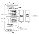
パスサーチ部30―1〜Nsは、サブキャリア信号に埋め込まれたパイロット信号を用いて遅延プロファイルを生成し、その上位受信電力のピークタイミングをパスタイミングとして検出する。ここで、あるサブキャリア信号群の第n番目のサブキャリア信号に対するパスサーチ部30−nにおける受信パスタイミング検出数をLnとする。だだし、n=1〜Nc。第k番目のアンテナ素子1―kで受信された第n番目のサブキャリア信号fn−kに対する、第j番目のパスタイミングtjにおけるパイロット信号相関値hnk(tj)は(数13)で表すことができる。ここで、パイロット信号をr(s)とする。ただし、s=1〜Npであり、Npはパイロット信号のシンボル数とする。
【0051】
【数13】
【0052】
相関行列生成部32は、パイロット信号相関演算部31において算出されたパイロット相関値hnk(tj)及び(数14)で示される相関ベクトルVn(tj)を用いて、(数15)に示される相関行列Rを算出する。ただし、n=1〜Ns、k=1〜Na、Hはベクトル複素共役転置を示す。
【0053】
【数14】
【数15】
【0055】
なお、相関行列生成部32おいて、相関ベクトルVn(tj)を合成後に、空間スペクトルを演算しているが、パス毎の相関ベクトルVn(tj)を用いて、(数16)に示すようにパス毎に空間プロファイル演算を行っても良い。なお、(数16)は、第n番目のサブキャリア信号に対する第j番目のパスの方向推定評価関数を示す。ただし、n=1〜Ns、j=1〜Lnである。
【0056】
【数16】
【0057】
【数17】
【数18】
【0059】
なお、サブキャリア伝送は、直交周波数分割多重(OFDM)されたサブキャリア信号でも良く、この場合、各サブキャリア信号がOFDMシンボル区間内で直交する周波数が選択され使用される。また、周波数軸方向に、符号拡散多重されるMC―CDMA方式への適用も可能であり、この場合、サブキャリア信号に埋め込まれた個別ユーザ毎に多重されたパイロット信号を用いて、ユーザ毎に各サブキャリア信号のパイロット相関値を算出することで、実施の形態で説明した動作を行うことで同様な効果が得られる。
【0060】
また、時間軸方向に符号拡散多重されるMC/DS−CDMA方式でも同様に適応が可能であり、この場合、各サブキャリア信号の時間軸方向に符号分割多重されたユーザ信号を、逆拡散により抽出後に、ユーザ毎に各サブキャリア信号のパイロット相関値を算出することで、実施の形態で説明した動作を行うことで同様な効果が得られる。
【0061】
また、符号分割多重されたユーザが存在する場合、分割帯域アレー重み生成部5は、所望ユーザの方向にサブキャリア信号群毎に分割帯域方向推定部4の推定方向に主ビームを有し、多重されている他ユーザの方向にはヌルを形成するアレー重みを生成することで、符号拡散多重されているユーザ間の干渉を低減させるビーム形成機能を付加してもよい。
【0062】
(実施の形態2)
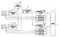
図5は、本発明の実施の形態2に係る適応アンテナ無線通信装置の構成を示すブロック図であり、実施の形態1で説明した図1の構成での、各分割帯域方向推定部4の方向推定結果を基にサブキャリア毎に送信指向性を形成する動作を行う。なお、分割帯域方向推定部4の方向推定結果が得られるまでのブロック図は実施の形態1と同様であり、省略している。図5における適応アンテナ無線通信装置は、分割帯域方向推定部4の推定結果を基に送信アレー重みを生成するサブキャリア送信重み生成部40、送信サブキャリア信号を送信アレー素子数分だけ複製したそれぞれの信号に、送信アレー重みを乗算するサブキャリア送信指向性形成部41、重み付けされたサブキャリア信号を混合する混合器42、混合器42の出力を無線周波数に周波数変換する無線送信部43から構成される。なお、図5ではアンテナ素子数Na=2、サブキャリア数Ns=2、分割帯域数Nd=2の場合の構成例を示している。以下、図5を用いてその動作の説明を行う。
【0063】
アレーアンテナ1で受信されたマルチキャリア方式で伝送された高周波信号s1を基に、分割帯域方向推定部4−1〜Ndで分割帯域毎に到来方向推定されるまでは実施の形態1と同様であり、ここでは説明を省略する。
【0064】
サブキャリア送信重み生成部40は、Nd個の分割帯域方向推定部4の推定結果を基に送信アレー重みを生成する。送信アレー重みの生成は、無線通信システムのデュプレックス方式により異なる動作を行う。例えば、時分割多重(TDD)方式、周波数多重(FDD)方式により、以下の異なる動作を行う。
【0065】
TDD方式の場合、送信帯域と受信帯域が時分割で共有されるため、分割帯域毎の分割帯域方向推定部4−1〜Ndでの推定方向結果を基に、分割帯域アレー重み生成部5−1〜Ndのそれぞれで生成されたアレー重みを送信アレー重みWsとして用いる。また、別な方式としては、分割帯域毎の分割帯域方向推定部4−1〜Ndでの方向推定結果の全通信帯域にわたる広がり(偏差)が大きい場合、符号拡散多重により複数ユーザが存在する無線通信システムの場合、ユーザ間干渉が大きくなるという課題が生じるため、以下の動作のいずれかを適用する。
【0066】
1)分割帯域毎の分割帯域方向推定部4−1〜Ndでの推定方向結果から、全分割帯域の中で最大受信電力を与える推定方向(分割帯域毎に分割帯域方向推定部4−1〜Ndでそれぞれ算出された空間プロファイルの中での最大ピーク方向)に送信指向性ビームを形成する送信アレー重みWsを生成する。
【0067】
2)分割帯域毎の分割帯域方向推定部4−1〜Ndでの推定方向結果から推定方向の全通信帯域での偏差を算出し、偏差が所定値より小さい場合には分割帯域方向推定部4−1〜Ndの各推定方向結果の平均方向に、所定値より大きい場合には、全分割帯域の中で受信電力上位の推定方向(分割帯域毎に分割帯域方向推定部4−1〜Ndでそれぞれ算出された空間プロファイルの中での上位のピーク方向)に複数の主ビームを向ける送信アレー重みWsを生成する。
【0068】
FDD方式の場合、送信帯域と受信帯域が異なるが、各分割帯域方向推定部4−1〜Ndの推定値を基に、以下の動作のいずれかを適用する。
【0069】
1)分割帯域毎の分割帯域方向推定部4−1〜Ndでの推定方向結果から、全分割帯域の中で最大受信電力を与える推定方向(分割帯域毎に分割帯域方向推定部4−1〜Ndでそれぞれ算出された空間プロファイルの中での最大ピーク方向)に送信指向性ビームを形成する送信アレー重みWsを生成する。
【0070】
2)分割帯域毎の分割帯域方向推定部4−1〜Ndでの推定方向結果から推定方向の全通信帯域での偏差を算出し、偏差が所定値より小さい場合には分割帯域方向推定部4−1〜Ndの各推定方向結果の平均方向に、所定値より大きい場合には、全分割帯域の中で受信電力上位の推定方向(分割帯域毎に分割帯域方向推定部4−1〜Ndでそれぞれ算出された空間プロファイルの中での上位のピーク方向)に複数の主ビームを向ける送信アレー重みWsを生成する。
【0071】
サブキャリア送信指向性形成部41−1〜Nsは、送信データを所定の変調フォーマットで変調された送信サブキャリア信号41−1〜Nsを、アレーアンテナ1の素子数Naに等しい数に分配し、それぞれに対し、送信アレー重みWs=[w1、w2、...、wna]の要素を乗算して混合器42―1〜Naに出力する。混合器42―1〜Naは、指向性重みづけされたサブキャリア送信指向性形成部41−1〜Nsのアレー素子数分の出力信号をそれぞれ割り当てられた周波数間隔でサブキャリア信号を配置するように混合する。無線送信部43―1〜Naは、混合器42―1〜Naの出力をそれぞれ無線周波数に周波数変換しアレーアンテナ44を構成するアンテナ素子44−1〜Naから送信する。
【0072】
以上のように、本実施の形態により、実施の形態1の効果に加え、分割帯域方向推定部4−1〜Ndでの推定方向に指向性送信することで、マルチパス干渉が低減され、通信品質が改善される。また、全分割帯域の中で最大受信電力を与える推定方向または、全通信帯域での分割帯域毎の方向推定値の偏差に応じて、指向性送信方向を分割帯域の中で受信電力がより高い方向に限定することで、ユーザ間干渉を抑えた形で、効率よく指向性送信ができるという効果が得られる。ユーザ間干渉を抑圧できシステム容量を改善できるという作用を有する。
【0073】
なお、送信で用いられるサブキャリア伝送は、直交周波数分割多重(OFDM)されたサブキャリア信号でも良く、この場合、各サブキャリア信号がOFDMシンボル区間内で直交する周波数が選択され使用される。また、周波数軸方向に、符号拡散多重されるMC―CDMA方式への適用も可能であり、ユーザ毎に実施の形態で説明した動作を行うことで同様な効果が得られる。また、時間軸方向に符号拡散多重されるMC/DS−CDMA方式でも同様に適応が可能であり、この場合もユーザ毎に、実施の形態で説明した動作を行うことで同様な効果が得られる。
【0074】
また、符号分割多重されたユーザが存在する場合、サブキャリア送信重み生成部40は、所望ユーザの方向にサブキャリア信号群毎に分割帯域方向推定部4の推定方向に主ビームを有し、多重されている他ユーザの方向にはヌルを形成するアレー重みを生成することで、符号拡散多重されているユーザ間の干渉を低減させるビーム形成機能を付加してもよい。
【0075】
(実施の形態3)
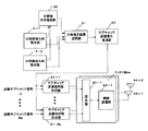
図6は、本発明の実施の形態3に係る適応アンテナ無線通信装置の構成を示すブロック図であり、実施の形態1で説明した図1に示す構成に、アレーアンテナ1で受信された全てのサブキャリア信号を用いることで全通信帯域での方向推定を行う全帯域方向推定部50と、分割帯域方向推定部4または、全帯域方向推定部50で算出される空間プロファイルを用いることで角度広がり検出し、どちらかの方向推定結果を選択して出力する方向推定結果選択部51とを追加した構成である。なお、分割帯域方向推定部4の方向推定結果が得られるまでのブロック図は実施の形態1と同様であり、省略している。以下、図6を用いて実施の形態1と異なる部分を主に説明を行う。なお、図6ではアンテナ素子数Na=2、サブキャリア数Ns=2、分割帯域数Nd=2の場合の構成例を示している。
【0076】
アレーアンテナ1で受信されたマルチキャリア方式で伝送された高周波信号s1を基に、分割帯域方向推定部4−1〜Ndで分割帯域毎に到来方向推定されるまでは実施の形態1と同様であり、ここでは説明を省略する。
【0077】
全帯域方向推定部50は、第n番目の分割帯域3−nで算出された(数7)で示される相関行列RをRnと表記したとき(ただし、n=1、...、Nd)、全ての分割帯域3−1〜Ndで算出されたRnを入力とし、(数19)で示されるRnの合成和Raを算出する。そして、例えば(数20)で示されるフーリエ法による空間プロファイルを、θを所定の角度ステップΔθで可変することで空間プロファイルを算出し、空間プロファイルのピークレベルの高い順に所定数M(M≧1)のピーク方向を検出し、全通信帯域でのサブキャリア信号の平均的な到来方向推定を行う。ただし、a(θ)はアレーアンテナ1の素子配置で決まる方向ベクトルであり、例えば素子間隔dの等間隔直線アレーの場合、(数9)のように表すことができる。ここで、λは搬送波の波長であり、θはアレーの法線方向を0°方向としている。また、Hは複素共役転置を表す。
【0078】
【数19】
【数20】
【0080】
【数21】
【数22】
【0082】
復調部7は、指向性受信された各サブキャリア信号を用いて、復調動作を行いデータ受信する。
【0083】
以上のように、本実施の形態により、実施の形態1での効果に加えて、方向推定結果選択部51により、全通信帯域でのサブキャリア信号の角度広がりを検出することで、全分割帯域毎に異なる指向性形成または、すべての分割帯域3に共通な指向性形成を、角度広がりASに応じて切り替えることができる。これにより、角度広がりASが小さい場合、すべてのサブキャリア信号に平均的な到来方向を推定することにより、周波数選択性フェージングにより、一部の帯域の受信レベルが低い場合でも、通信帯域全体ではロバストな到来方向推定が可能となる。
【0084】
なお、方向推定結果選択部51における角度広がり検出は、分割帯域毎の到来方向推定値の広がりを基に算出したが、全帯域方向推定部50で算出される空間プロファイルを基に検出する方法も適用可能である。空間プロファイルより角度広がりを算出する方法としては、例えば、N.S.M.Shah他、“MUSICアルゴリズムを用いた到来方向と角度広がりの同時推定”、2000年電子情報通信学会通信ソサエティ大会B-1-31に情報開示されている。(数19)で算出される相関行列Raから空間プロファイルより算出した角度広がりASを用いて同様に、全帯域方向推定部50または分割帯域方向推定部4−1〜Ndの推定結果を選択的に切り替えることができる。
【0085】
なお、本実施の形態では、全通信帯域のサブキャリア信号を用いた方向推定を行う全帯域方向推定部50を用いたが、全帯域方向推定部50は、分割帯域方向推定部4に用いるサブキャリア信号分割数Nsよりも大きい分割数での方向推定を行う構成でも良い。
【0086】
なお、本実施の形態における全分割帯域方向推定部50では、ビームフォーマ法を用いて方向推定をおこなっているが、菊間著、「アレーアンテナによる適応信号処理」(科学技術出版)等で情報開示されているMUSIC法、ESPRIT法といった固有値分解手法や、相関行列の逆行列演算を含むCapon法等の到来方向推定の高分解能手法を、(数19)で示される相関行列Raを用いて適用することが可能である。ただし、分割帯域3に属するサブキャリア信号数Nc、あるいはパス数がアレー素子数よりも小さい場合は、相関行列生成部22の出力である相関行列のランク数がフルランクにならないケースが考えられるため、ランク数、あるいはパス数に応じて、ビームフォーマ法との適応的な併用が考えられる。また、アレーアンテナ1の構成が等間隔直線アレー配置である場合、(数19)で示される相関行列Raに対し、空間スムージング処理や、ユニタリ変換行列を乗算することでの方向ベクトルを実数化したビームスペースでの到来方向推定処理も同様に適用可能である。
【0087】
なお、サブキャリア伝送は、直交周波数分割多重(OFDM)されたサブキャリア信号でも良く、この場合、各サブキャリア信号がOFDMシンボル区間内で直交する周波数が選択され使用される。また、周波数軸方向に、符号拡散多重されるMC―CDMA方式への適用も可能であり、この場合、サブキャリア信号に埋め込まれた個別ユーザ毎に多重されたパイロット信号を用いて、ユーザ毎に各サブキャリア信号のパイロット相関値を算出することで、実施の形態で説明した動作を行うことで同様な効果が得られる。
【0088】
また、時間軸方向に符号拡散多重されるMC/DS−CDMA方式でも同様に適応が可能であり、この場合、各サブキャリア信号の時間軸方向に符号分割多重されたユーザ信号を、逆拡散により抽出後に、ユーザ毎に各サブキャリア信号のパイロット相関値を算出することで、実施の形態で説明した動作を行うことで同様な効果が得られる。
【0089】
また、符号分割多重されたユーザが存在する場合、分割帯域アレー重み生成部5は、所望ユーザの方向にサブキャリア信号群毎に方向推定結果選択部51の選択された推定方向に主ビームを有し、多重されている他ユーザの方向にはヌルを形成するアレー重みを生成することで、符号拡散多重されているユーザ間の干渉を低減させるビーム形成機能を付加してもよい。
【0090】
(実施の形態4)
図7は、本発明の実施の形態4に係る適応アンテナ無線通信装置の構成を示すブロック図であり、実施の形態2で説明した図5に示す構成に、アレーアンテナ1で受信された全てのサブキャリア信号を用いることで全帯域での方向推定を行う全帯域方向推定部50と、分割帯域方向推定部4または、全帯域方向推定部50で算出される空間プロファイルを用いることで角度広がり検出し、どちらかの方向推定結果を選択して出力する方向推定結果選択部51とを追加した構成である。なお、分割帯域方向推定部4の方向推定結果が得られるまでのブロック図は実施の形態1と同様であり、省略している。以下、図7を用いて実施の形態1と異なる部分を主に説明を行う。なお、図7ではアンテナ素子数Na=2、サブキャリア数Ns=2、分割帯域数Nd=2の場合の構成例を示している。
【0091】
アレーアンテナ1で受信されたマルチキャリア方式で伝送された高周波信号s1を基に、分割帯域方向推定部4−1〜Ndで分割帯域毎に到来方向推定されるまでは実施の形態1と同様であり、ここでは説明を省略する。
【0092】
全帯域方向推定部50は、実施の形態3で説明した動作と同様に、第n番目の分割帯域3−nで算出された(数7)で示される相関行列RをRnと表記したとき(ただし、n=1、...、Nd)、全ての分割帯域3−1〜Ndで算出されたRnを入力とし、(数19)で示されるRnの合成和Raを算出する。そして、例えば(数20)で示されるフーリエ法による空間プロファイルを、θを所定の角度ステップΔθで可変することで空間プロファイルを算出し、空間プロファイルのピークレベルの高い順に所定数M(M≧1)のピーク方向を検出し、全通信帯域でのサブキャリア信号の平均的な到来方向推定を行う。ただし、a(θ)はアレーアンテナ1の素子配置で決まる方向ベクトルであり、例えば素子間隔dの等間隔直線アレーの場合、(数9)のように表すことができる。ここで、λは搬送波の波長であり、θはアレーの法線方向を0°方向としている。また、Hは複素共役転置を表す。
【0093】
方向推定結果選択部51は、全ての分割帯域方向推定部4−1〜Ndの方向推定値Φkmと、それぞれの分割帯域3―mでの空間プロファイル値(または到来方向推定評価関数値)Fm(Φkm)を用いて、(数21)に示される計算式を用いて角度広がりASを算出する。ここで、m=1、...、Ndである。また、φ0は(数22)で与えられ、Φkmは、第m番目の分割帯域3−mでの分割帯域方向推定部4−mで検出された全Lm個のパスのうち、第k番目のパスの到来方向を示す。算出された角度広がりASを用いて、角度広がりASが所定値K以下の場合、全帯域方向推定部50の推定値を選択し、サブキャリア送信重み生成部40に出力する。一方、角度広がりASが所定値Kより大きい場合、実施例2の形態と同様に、各分割帯域3−1〜Ndでの分割帯域方向推定部4−1〜Ndの推定値を、サブキャリア送信重み生成部40に出力する。ここで、m=1、...、Ndである。また、角度広がりASの別な算出方法としては、空間プロファイル値(または到来方向推定評価関数値)Fm(Φkm)の上位を与える方向推定値Φkmのみを用いて、(数21)から角度広がりASを求めても良い。
【0094】
サブキャリア送信重み生成部40は、方向推定結果選択部51の出力を基に送信アレー重みを生成する。角度広がりASが所定値Kより大きい場合、各分割帯域3−1〜Ndでの分割帯域方向推定部4−1〜Ndの推定値が入力されるので、実施例2の形態におけるサブキャリア送信重み生成部40と同様な動作を行うので、ここでは説明を省略する。角度広がりASが所定値K以下の場合、全帯域方向推定部50の推定値が選択されて入力されるので、方向推定値の方向に主ビームを向ける送信アレー重みを生成する。
【0095】
サブキャリア送信指向性形成部41−1〜Nsは、送信データを所定の変調フォーマットで変調された送信サブキャリア信号41−1〜Nsを、アレーアンテナ1の素子数Naに等しい数に分配し、それぞれに対し、送信アレー重みWs=[w1、w2、...、wna]の要素を乗算して混合器42―1〜Naに出力する。混合器42―1〜Naは、指向性重みづけされたサブキャリア送信指向性形成部41−1〜Nsのアレー素子数分の出力信号をそれぞれ割り当てられた周波数間隔でサブキャリア信号を配置するように混合する。無線送信部43―1〜Naは、混合器42―1〜Naの出力をそれぞれ無線周波数に周波数変換しアレーアンテナ44を構成するアンテナ素子44−1〜Naから送信する。
【0096】
以上のように、本実施の形態により、実施の形態1及び実施の形態2の効果に加え、全分割帯域毎に異なる指向性形成または、すべての分割帯域3に共通な送信指向性形成を、角度広がりASに応じて切り替えることができる。これにより、角度広がりASが小さい場合、すべてのサブキャリア信号に平均的な到来方向を推定することにより、周波数選択性フェージングにより、一部の帯域の受信レベルが低い場合でも、通信帯域全体ではロバストな到来方向推定が可能となり、その結果を用いる指向性送信は、より安定した動作が保証されるという効果が得られ、ユーザ間干渉を抑圧できシステム容量を改善できるという作用を有する。
【0097】
なお、本実施の形態では、全通信帯域のサブキャリア信号を用いた方向推定を行う全帯域方向推定部50を用いたが、全帯域方向推定部50は、分割帯域方向推定部4に用いるサブキャリア信号分割数Nsよりも大きい分割数での方向推定を行う構成でも良い。
【0098】
なお、サブキャリア伝送は、直交周波数分割多重(OFDM)されたサブキャリア信号でも良く、この場合、各サブキャリアがOFDMシンボル区間内で直交する周波数を選択して使用される。また、周波数軸方向に、符号多重拡散されるMC―CDMA方式への適用も可能であり、この場合、符号分割多重されたユーザ毎に、拡散符号の逆拡散後にユーザ信号を抽出後に実施の形態で説明した動作を行う。
【0099】
また、時間軸方向に符号多重されるMC―DS−CDMA方式でも同様に適応が可能であり、この場合、符号分割多重されたユーザ毎に、拡散符号の逆拡散後にユーザ信号を抽出後に実施の形態で説明した動作を行う。
【0100】
また、符号分割多重されたユーザが存在する場合、サブキャリア送信重み生成部40は、所望ユーザの方向にサブキャリア信号群毎に方向推定結果選択部51による選択された推定方向に主ビームを有し、多重されている他ユーザの方向にはヌルを形成するアレー重みを生成することで、符号拡散多重されているユーザ間の干渉を低減させるビーム形成機能を付加してもよい。
【0101】
【発明の効果】
以上のように本発明によれば、アレーアンテナを備えた適応アンテナ無線通信装置において、広帯域なマルチキャリア伝送方式を行う場合において、隣接するサブキャリア信号間での空間的なスペクトラムの相関が高いことを利用し、通信帯域内を分割した分割帯域内に属するサブキャリア信号群の平均的な到来方向を推定することで、受信電力が小さいサブキャリアが存在する場合でも、それが属するサブキャリア信号群としての到来方向を推定することで、推定精度の劣化を抑えることを可能にしており、ロバスト化した方向推定結果を用いて指向性受信を行うことで受信品質の改善が可能となる。また、指向性送信する場合、全通信帯域での空間プロファイルをもとに角度広がりを検出することで、角度広がりに応じて、指向性送信方法を切替えることで、ユーザ間干渉と低減させ通信品質の改善を図ることができる。
【図面の簡単な説明】
【図1】本発明の実施の形態1における無線通信装置の構成を示すブロック図
【図2】実施の形態1における分割帯域方向推定部の詳細な構成を示すブロック図
【図3】実施の形態1における分割帯域方向推定部での空間プロファイル算出結果を示す図
【図4】実施の形態1における分割帯域方向推定部の別な構成を示すブロック図
【図5】本発明の実施の形態2における無線通信装置の構成を示すブロック図
【図6】本発明の実施の形態3における無線通信装置の構成を示すブロック図
【図7】本発明の実施の形態4における無線通信装置の構成を示すブロック図
【符号の説明】
1 アレーアンテナ
1―1〜Na アンテナ素子
2―1〜Na 分波器
3―1〜Nd 分割帯域
4―1〜Nd 分割帯域方向推定部
5―1〜Nd 分割帯域アレー重み生成部
6―1〜Nd サブキャリア指向性形成部
7 復調部[0001]
BACKGROUND OF THE INVENTION
The present invention relates to a multi-carrier transmission type digital radio communication system using a plurality of subcarriers having different frequencies, and an adaptive antenna radio communication apparatus having an array antenna having a direction estimation means of an incoming path and a directivity control means based thereon. About.
[0002]
[Prior art]
Signals received by the wireless communication device are subject to interference due to various signals, resulting in degradation of reception quality. An adaptive array antenna (adaptive antenna) is known as a technique for suppressing this interference and receiving only a signal arriving from a desired direction. In an adaptive array antenna, a signal arriving from a desired direction is adjusted by adjusting a weighting coefficient to be multiplied to a received signal (hereinafter, this weighting coefficient is referred to as “weight”) and adjusting an amplitude and a phase applied to the received signal. Only can be received strongly.
[0003]
In recent years, there has been a growing demand for higher capacity and higher speed of wireless communication, and multipath resistance and anti-fading countermeasures have become major issues for its realization. Multi-carrier transmission, in which a wide band transmission is performed in parallel by a plurality of narrow-band subcarriers, is one approach for solving the problem. In particular, orthogonal frequency division multiplexing (OFDM) transmission is a digital terrestrial signal. It is used in broadcasting and broadband wireless access systems.
[0004]
By using an adaptive array antenna in a multicarrier transmission system, the characteristics of both can be further utilized, and multipath resistance and fading resistance can be further improved.
[0005]
Although a detailed description of the configuration is omitted, in a multi-carrier transmission system, as a conventional radio apparatus having an adaptive array antenna, by calculating an antenna weight for each subcarrier, a specific band (= total communication band / Even when the center frequency of the entire communication band is large, a uniform antenna directional beam can be obtained in the entire communication band of the OFDM transmission method, enabling transmission and reception that is less susceptible to interference waves such as multipath within the entire communication band. (For example, refer to Patent Document 1).
[0006]
[Patent Document 1]
JP-A-11-205026
[0007]
[Problems to be solved by the invention]
However, in the conventional adaptive antenna wireless communication apparatus, direction estimation is performed for each subcarrier and the array weight is calculated. Therefore, when affected by frequency selective fading, it is sufficient for subcarrier signals with low received power. There arises a problem that direction estimation cannot be performed with high accuracy. Further, when the number of subcarriers is large, there is a problem that the circuit scale increases when the direction is estimated for each subcarrier.
[0008]
The present invention uses a high spatial spectrum correlation between adjacent subcarrier signals when performing a broadband multicarrier transmission system, and uses subcarrier signals belonging to a divided band obtained by dividing a communication band. By estimating the average direction of arrival of a group, even when there are subcarriers with low received power, it is possible to suppress the degradation of estimation accuracy by estimating the direction of arrival as a subcarrier signal group to which the subcarrier belongs. It is possible. In addition, individual or average direction estimation of a plurality of paths for each subcarrier signal is also possible.
[0009]
When directional transmission is performed, the angular spread is detected based on the spatial spectrum in each divided band or in the entire communication band. When the angular spread is small, the average arrival direction of all subcarrier signal groups is detected. When the transmission directivity control is performed based on a large angle spread, 1) directivity transmission control in the direction that gives the maximum received power among the direction estimation results for each divided band, or 2) the direction estimation result for each divided band The directivity transmission control is performed in a direction in which a predetermined number of higher received power is applied. As a result, directional transmission can be performed in the direction of the arrival path at the time of reception, interference with other users can be effectively reduced, communication quality can be improved, and system capacity can be improved.
[0010]
[Means for Solving the Problems]
An adaptive antenna wireless communication apparatus according to the present invention includes an array antenna composed of a plurality of antenna elements that receive a high-frequency signal transmitted by multicarrier, and a high-frequency signal received for each antenna element is divided into a plurality of subcarrier signals. A wave splitter and a multi-carrier transmission total communication band is divided into Nd (where Nd is 2 or more and a natural number less than the number of subcarriers used for multi-carrier transmission). Nd subband direction estimation units that perform radio wave arrival direction estimation using the subcarrier signal group to which the subcarrier signals belong, and an array weight having a directional beam in the estimation direction of the subband direction estimation unit for each of the subbands A subband array weight generation unit, and each subcarrier belonging to the subband corresponding to the array weight generated for each subband Taking a subcarrier beamforming unit for directivity formed by multiplying synthesized No., the arrangement comprising a demodulator for data demodulation using the output of the sub-carrier directivity forming section.
[0011]
DETAILED DESCRIPTION OF THE INVENTION
According to the first aspect of the present invention, there is provided an array antenna composed of a plurality of antenna elements that receive a high-frequency signal transmitted in a multicarrier manner, and a plurality of subcarrier signals for the high-frequency signal received for each antenna element. And the total communication band for multi-carrier transmission is divided into Nd (where Nd is 2 or more and a natural number less than the number of subcarriers used for multi-carrier transmission). Nd subband direction estimation units that perform radio wave arrival direction estimation using subcarrier signal groups that belong to a band, and array weights having directional beams in the estimation direction of the subband direction estimation unit for each of the subbands Division band array weight generation unit to be generated, and each subcarrier signal belonging to the division band corresponding to the array weight generated for each division band A subcarrier directivity forming unit for forming directivity by multiplication and synthesis; and a demodulating unit for demodulating data using an output of the subcarrier directivity forming unit. The arrival direction of the carrier signal group can be estimated, and directivity reception based on the direction estimation result can be performed.
[0012]
According to the second aspect of the present invention, the division band direction estimation unit calculates a pilot signal correlation value with each input subcarrier signal using a known pilot signal embedded in the subcarrier signal. The direction of arrival is estimated based on the correlation value of the pilot signal correlation value calculated between subcarrier signals received by different antenna elements, and the direction can be estimated based on the phase of the pilot correlation value It has the action.
[0013]
In the invention according to claim 3 of the present invention, the divided band direction estimation unit includes L subcarriers belonging to the subcarrier signal group and a column vector VkIs the pilot signal correlation value at the mth antenna element in the kth subcarrier signal and H is the complex conjugate transpose operator, then R = V1V1 H+ V2V2 H+ ... + VLVL HThe direction of arrival is estimated using a correlation matrix R expressed as follows, and it has the effect of accurately detecting the direction in which the directions of arrival of subcarrier signal groups are averaged.
[0014]
In the invention according to
[0015]
According to the fifth aspect of the present invention, the subband direction estimation unit performs a cross-correlation operation with each input subcarrier signal using a known pilot signal embedded in the subcarrier signal. A delay profile is calculated, a plurality of path arrival timings are detected from the delay profile, and a correlation value of the pilot signal correlation value calculated between subcarrier signals received by different antenna elements is determined for each arrival path timing. It is characterized in that arrival direction estimation is performed based on this, and has the effect that the arrival direction of a multipath wave included in each subcarrier signal can be estimated.
[0016]
In the invention according to
[Equation 3]
[0017]
In the invention according to
[Expression 4]
[0018]
In the invention according to claim 8 of the present invention, the divided band direction estimation unit uses the correlation matrix R and performs direction of arrival estimation using any one of the MUSIC method, ESPRIT method, CAPON method, and Fourier method. It has the effect that various arrival direction estimation methods can be applied.
[0019]
In the invention according to claim 9 of the present invention, the divided band direction estimation unit uses any one of the MUSIC method, the ESPRIT method, the CAPON method, or the Fourier method after applying the spatial smoothing process to the correlation matrix R. It is characterized by direction-of-arrival estimation, and has the effect of ensuring the estimation accuracy even when a correlation wave exists.
[0020]
According to the tenth aspect of the present invention, the division band direction estimation unit uses any one of the MUSIC method, ESPRIT method, CAPON method, and Fourier method after applying the unitary transformation process to the correlation matrix R. The direction of arrival is estimated, and when the array antenna is an equally spaced linear array, the direction vector can be converted to a real number, so that the amount of calculation processing can be reduced.
[0021]
According to an eleventh aspect of the present invention, the deviation of the direction estimation result between the all-band direction estimating unit that performs direction-of-arrival estimation using subcarrier signals in all communication bands and the Nd divided band direction estimating units. When the value is equal to or less than a predetermined value, the estimated value of the all-band direction estimating unit is selected and output, and when the deviation is larger than the predetermined value, the direction estimation result selecting unit that outputs the estimated value of the divided band direction estimating unit; A division band array generation unit that generates an array weight using an output of the direction estimation result selection unit, and adaptively switches the directivity control method from dispersion of arrival directions within the band. Has the effect of being able to.
[0022]
According to a twelfth aspect of the present invention, there is provided an all-band direction estimating unit that performs direction-of-arrival estimation using subcarrier signals in all communication bands, and an angular spread from a spatial profile calculated by the all-band direction estimating unit. When the angular spread is equal to or smaller than a predetermined value, the estimated value of the all-band direction estimating unit is selected and output. When the angular spread is larger than the predetermined value, the estimated value of the divided band direction estimating unit is output. A direction estimation result selection unit; and a subband array generation unit that generates an array weight using an output of the direction estimation result selection unit. This has the effect that the sex control method can be switched.
[0023]
According to a thirteenth aspect of the present invention, in a wireless system in which multicarrier transmission is performed using a time division duplex (TDD) scheme or a frequency division duplex (FDD) scheme, an estimation direction result selected by a direction estimation result selection unit is displayed. A subcarrier transmission weight generation unit that calculates a transmission array weight for forming one transmission directional beam for each divided band, and a directivity by multiplying the transmission subcarrier signal by the transmission array weight for each divided band. And a subcarrier transmission directivity forming unit that performs beam transmission, and has an effect that the directivity control method can be switched adaptively from the spread of the arrival direction in the band.
[0024]
According to a fourteenth aspect of the present invention, in a radio system that performs multicarrier transmission using a time division duplex (TDD) method, an array weight generated by a divided band array weight generation unit for each divided band is used as a transmission array weight. A subcarrier transmission weight generation unit to be used; and a subcarrier transmission directivity formation unit that transmits a directional beam using a transmission array weight common to each of the divided bands. It has the effect that transmission can be performed using the same directivity as the sex.
[0025]
According to a fifteenth aspect of the present invention, in a wireless system in which multicarrier transmission is performed using a time division duplex (TDD) scheme or a frequency division duplex (FDD) scheme, an estimated direction in a divided band direction estimation unit for each divided band. From the results, a subcarrier transmission weight generation unit that calculates a transmission array weight for forming a transmission directional beam in an estimated direction giving the maximum received power among the divided bands, and a common directivity in all divided bands using the transmission array weights. And a sub-carrier transmission directivity forming unit that transmits a transmission beam, and has an effect that a transmission beam can be formed in a path direction that gives the maximum reception power in the divided band.
[0026]
According to a sixteenth aspect of the present invention, in a wireless system that performs multicarrier transmission using a time division duplex (TDD) scheme or a frequency division duplex (FDD) scheme, an estimated direction in a divided band direction estimation unit for each divided band. The deviation of the estimated direction is calculated from the result. If the deviation is equal to or smaller than a predetermined value, the average direction of all the direction estimation values obtained by the divided band direction estimation unit is determined. A subcarrier transmission weight generation unit that calculates a transmission array weight that forms a transmission directional beam that becomes a multi-beam in an estimated direction that gives a higher number of received power, and from the spread of arrival directions in a band It has the effect that the directivity control method can be switched adaptively.
[0027]
The invention according to claim 17 of the present invention is the adaptive antenna radio communication apparatus according to any one of
[0028]
According to an eighteenth aspect of the present invention, the subcarrier transmission is a subcarrier signal that is user-multiplexed by code spread multiplexing in the frequency axis direction. The adaptive antenna wireless communication apparatus of the present invention is characterized in that it can be applied to a system capable of user multiplexing by code spread multiplexing.
[0029]
The invention according to claim 19 of the present invention is the subcarrier signal according to any one of
[0030]
According to the twentieth aspect of the present invention, in the case of subcarrier transmission using a subcarrier signal that is user-multiplexed by code spreading multiplexing, a transmission array weight or a reception array weight is generated for each multiplexed user, and The adaptive antenna wireless communication apparatus according to any one of claims 18 to 19, characterized in that optimal directivity control is possible for each divided band for each of multiple users. Have.
[0031]
In the invention according to claim 21 of the present invention, the division band array weight generation unit has a directional beam in the direction estimation result of the division band direction estimation unit in the corresponding division band, and is multiplexed by other users. 21. The adaptive antenna radio communication apparatus according to
[0032]
According to a twenty-second aspect of the present invention, the subcarrier transmission weight generation unit generates a transmission division band array weight having a directional beam in a desired user direction and forming a null in another multiplexed user direction. 21. The adaptive antenna wireless communication apparatus according to
[0033]
Hereinafter, embodiments of the present invention will be described with reference to FIGS.
[0034]
(Embodiment 1)
FIG. 1 is a block diagram showing a configuration of an adaptive antenna radio communication apparatus according to
[0035]
The operation will be described below with reference to FIG. First, the high frequency signals s1-1 to Na transmitted by the multicarrier system are received by the antenna elements 1-1 to Na constituting the
[0036]
Using the subcarrier signal group belonging to the m-th divided band 3-m, the divided band direction estimation unit 4-m performs direction-of-arrival estimation. FIG. 2 shows a detailed configuration diagram of the divided band
[0037]
The pilot
[0038]
[Equation 5]
[0039]
[Formula 6]
[Expression 7]
[0041]
The spatial profile calculation unit 23 calculates a spatial profile by varying the parameter θ in the direction-of-arrival estimation evaluation function F (θ) shown in (Equation 8) by a predetermined angle step Δθ, and increases the peak level of the spatial profile in descending order. A predetermined number M (M ≧ 1) of peak directions are detected and set as arrival direction estimation values. However, a (θ) is a direction vector determined by the element arrangement of the
[0042]
[Equation 8]
[Equation 9]
[0044]
The subband array weight generation unit 5-m applies the maximum peak direction or the predetermined number of direction estimation results in the subband direction estimation unit 4-m to the subcarrier signal group belonging to the mth subband 3-m. An array weight for directing the main beam in a plurality of peak directions is generated, and the subcarrier directivity forming unit 6-m outputs a signal obtained by multiplying and combining the generated array weight by each subcarrier signal. The array weight is generated in consideration of the wavelength λm of the center frequency of each divided band 3-m in the radio frequency band. This is particularly effective when the ratio band is large. For example, in the case of an equally spaced linear array with element spacing d, the array weight Wm in the m-th divided band 3-m can be expressed as (Equation 10). Where θ0Is the direction estimation result. The normal direction of the linear array is set to 0 °.
[0045]
[Expression 10]
[0046]
In the present embodiment, by generating a correlation matrix R that combines the correlation vectors Vn obtained from the subcarrier signals belonging to the subcarrier signal group belonging to the divided band 3, and performing arrival direction estimation using the correlation matrix R, It is possible to estimate the average direction of arrival of the subcarrier signal group within the divided band. As a result, when the frequency interval between subcarrier signals is sufficiently narrow, the spatial correlation characteristics between adjacent subcarrier signals are relatively high, and even if the received power per subcarrier signal is small, those subcarriers Since direction estimation is performed after in-phase synthesis of signals, there is an effect that the arrival direction estimation accuracy can be ensured. When the frequency interval between the subcarrier signals is sufficiently wide, there is an effect of stabilizing the direction estimation accuracy due to the frequency diversity effect.
[0047]
Note that the correlation
[0048]
## EQU11 ##
[Expression 12]
[0050]
The path search units 30-1 to Ns generate a delay profile using the pilot signal embedded in the subcarrier signal, and detect the peak timing of the higher received power as the path timing. Here, the number of detected reception path timings in the path search unit 30-n for the nth subcarrier signal of a certain subcarrier signal group is Ln. However, n = 1 to Nc. The jth path timing t for the nth subcarrier signal fn-k received by the kth antenna element 1-k.jPilot signal correlation value hnk(Tj) Can be expressed by (Equation 13). Here, the pilot signal is r (s). However, s = 1 to Np, and Np is the number of symbols of the pilot signal.
[0051]
[Formula 13]
[0052]
The correlation
[0053]
[Expression 14]
[Expression 15]
[0055]
In the correlation
[0056]
[Expression 16]
[0057]
[Expression 17]
[Formula 18]
[0059]
The subcarrier transmission may be an orthogonal frequency division multiplexing (OFDM) subcarrier signal. In this case, a frequency at which each subcarrier signal is orthogonal within the OFDM symbol section is selected and used. Also, it can be applied to the MC-CDMA system that is code spread multiplexed in the frequency axis direction. In this case, the pilot signal multiplexed for each individual user embedded in the subcarrier signal is used for each user. By calculating the pilot correlation value of each subcarrier signal, the same effect can be obtained by performing the operation described in the embodiment.
[0060]
In addition, the MC / DS-CDMA system in which code spread multiplexing is performed in the time axis direction can be similarly applied. In this case, the user signal code-division multiplexed in the time axis direction of each subcarrier signal is despread. By calculating the pilot correlation value of each subcarrier signal for each user after extraction, the same effect can be obtained by performing the operation described in the embodiment.
[0061]
When there is a code division multiplexed user, the division band array weight generation unit 5 has a main beam in the estimation direction of the division band
[0062]
(Embodiment 2)
FIG. 5 is a block diagram showing the configuration of the adaptive antenna radio communication apparatus according to
[0063]
Based on the high-frequency signal s1 transmitted by the multi-carrier method received by the
[0064]
The subcarrier transmission
[0065]
In the case of the TDD scheme, the transmission band and the reception band are shared in a time division manner. Therefore, based on the estimation direction results in the division band direction estimation units 4-1 to Nd for each division band, the division band array weight generation unit 5- The array weight generated by each of 1 to Nd is used as the transmission array weight Ws. As another method, when the spread (deviation) over the entire communication band of the direction estimation results in the divided band direction estimation units 4-1 to Nd for each divided band is large, there is a radio in which a plurality of users exist by code spread multiplexing. In the case of a communication system, there arises a problem that inter-user interference increases, and therefore any one of the following operations is applied.
[0066]
1) From the estimation direction results in the divided band direction estimation units 4-1 to Nd for each divided band, the estimated direction giving the maximum received power in all divided bands (the divided band direction estimating units 4-1 to 4-1 for each divided band) A transmission array weight Ws that forms a transmission directional beam in the maximum peak direction in the spatial profile calculated with Nd is generated.
[0067]
2) Deviations in all communication bands in the estimated direction are calculated from the estimation direction results in the divided band direction estimation units 4-1 to Nd for each divided band, and when the deviation is smaller than a predetermined value, the divided band
[0068]
In the case of the FDD scheme, although the transmission band and the reception band are different, one of the following operations is applied based on the estimated values of the respective divided band direction estimation units 4-1 to Nd.
[0069]
1) From the estimation direction results in the divided band direction estimation units 4-1 to Nd for each divided band, the estimated direction giving the maximum received power in all divided bands (the divided band direction estimating units 4-1 to 4-1 for each divided band) A transmission array weight Ws that forms a transmission directional beam in the maximum peak direction in the spatial profile calculated with Nd is generated.
[0070]
2) Deviations in all communication bands in the estimated direction are calculated from the estimation direction results in the divided band direction estimation units 4-1 to Nd for each divided band, and when the deviation is smaller than a predetermined value, the divided band
[0071]
Subcarrier transmission directivity forming sections 41-1 to Ns distribute transmission subcarrier signals 41-1 to Ns obtained by modulating transmission data in a predetermined modulation format to a number equal to the number of elements Na of
[0072]
As described above, according to the present embodiment, in addition to the effects of the first embodiment, multipath interference is reduced by performing directional transmission in the estimated direction in the divided band direction estimation units 4-1 to Nd, and the communication Quality is improved. In addition, in the estimated direction that gives the maximum received power in all the divided bands or the deviation of the direction estimation value for each divided band in all the communication bands, the received power is higher in the directional transmission direction in the divided bands. By limiting to the direction, there is an effect that the directional transmission can be efficiently performed in a form in which the interference between users is suppressed. Interference between users can be suppressed and system capacity can be improved.
[0073]
The subcarrier transmission used for transmission may be an orthogonal frequency division multiplexed (OFDM) subcarrier signal. In this case, a frequency at which each subcarrier signal is orthogonal in the OFDM symbol section is selected and used. Also, it can be applied to the MC-CDMA system that is code spread multiplexed in the frequency axis direction, and the same effect can be obtained by performing the operation described in the embodiment for each user. In addition, the MC / DS-CDMA system in which code spread multiplexing is performed in the time axis direction can be similarly applied. In this case, the same effect can be obtained by performing the operation described in the embodiment for each user. .
[0074]
In addition, when there is a code division multiplexed user, the subcarrier transmission
[0075]
(Embodiment 3)
FIG. 6 is a block diagram showing the configuration of the adaptive antenna radio communication apparatus according to Embodiment 3 of the present invention. In the configuration shown in FIG. 1 described in
[0076]
Based on the high-frequency signal s1 transmitted by the multi-carrier method received by the
[0077]
When the correlation matrix R represented by (Equation 7) calculated in the n-th divided band 3-n is expressed as Rn (where n = 1,..., Nd) Then, Rn calculated in all the divided bands 3-1 to Nd is used as an input, and a combined sum Ra of Rn expressed by (Equation 19) is calculated. Then, for example, a spatial profile is calculated by varying the θ by a predetermined angle step Δθ, and the predetermined number M (M ≧ 1) in descending order of the peak level of the spatial profile. ) Is detected, and the average direction of arrival of subcarrier signals in all communication bands is estimated. However, a (θ) is a direction vector determined by the element arrangement of the
[0078]
[Equation 19]
[Expression 20]
[0080]
[Expression 21]
[Expression 22]
[0082]
The
[0083]
As described above, according to the present embodiment, in addition to the effects of the first embodiment, the direction estimation
[0084]
The angle spread detection in the direction estimation
[0085]
In the present embodiment, the all-band
[0086]
Note that the all-divided band
[0087]
The subcarrier transmission may be an orthogonal frequency division multiplexing (OFDM) subcarrier signal. In this case, a frequency at which each subcarrier signal is orthogonal within the OFDM symbol section is selected and used. Also, it can be applied to the MC-CDMA system that is code spread multiplexed in the frequency axis direction. In this case, the pilot signal multiplexed for each individual user embedded in the subcarrier signal is used for each user. By calculating the pilot correlation value of each subcarrier signal, the same effect can be obtained by performing the operation described in the embodiment.
[0088]
In addition, the MC / DS-CDMA system in which code spread multiplexing is performed in the time axis direction can be similarly applied. In this case, the user signal code-division multiplexed in the time axis direction of each subcarrier signal is despread. By calculating the pilot correlation value of each subcarrier signal for each user after extraction, the same effect can be obtained by performing the operation described in the embodiment.
[0089]
Also, when there is a code division multiplexed user, the division band array weight generation unit 5 has a main beam in the estimated direction selected by the direction estimation
[0090]
(Embodiment 4)
FIG. 7 is a block diagram showing the configuration of the adaptive antenna radio communication apparatus according to
[0091]
Based on the high-frequency signal s1 transmitted by the multi-carrier method received by the
[0092]
Similar to the operation described in the third embodiment, the all-band
[0093]
The direction estimation
[0094]
The subcarrier transmission
[0095]
Subcarrier transmission directivity forming sections 41-1 to Ns distribute transmission subcarrier signals 41-1 to Ns obtained by modulating transmission data in a predetermined modulation format to a number equal to the number of elements Na of
[0096]
As described above, according to the present embodiment, in addition to the effects of the first embodiment and the second embodiment, the directivity formation different for all the divided bands or the transmission directivity formation common to all the divided bands 3 is obtained. It can be switched according to the angular spread AS. As a result, when the angular spread AS is small, by estimating the average direction of arrival for all subcarrier signals, even if the reception level of some bands is low due to frequency selective fading, the entire communication band is robust. Directional transmission using the result is effective, and an effect that more stable operation is ensured is obtained. Interference between users can be suppressed and system capacity can be improved.
[0097]
In the present embodiment, the all-band
[0098]
The subcarrier transmission may be an orthogonal frequency division multiplexed (OFDM) subcarrier signal. In this case, the subcarrier transmission is used by selecting a frequency at which each subcarrier is orthogonal within the OFDM symbol section. Further, the present invention can also be applied to an MC-CDMA system that is code-multiplexed and spread in the frequency axis direction. Perform the operation described in.
[0099]
In addition, the MC-DS-CDMA system that is code-multiplexed in the time axis direction can be similarly applied. In this case, for each user that has been code-division-multiplexed, the user signal is extracted after despreading the spreading code. The operation described in the embodiment is performed.
[0100]
When there is a user that is code-division multiplexed, the subcarrier transmission
[0101]
【The invention's effect】
As described above, according to the present invention, in an adaptive antenna wireless communication apparatus equipped with an array antenna, when performing a wideband multicarrier transmission scheme, the spatial spectrum correlation between adjacent subcarrier signals is high. Even if there is a subcarrier with low received power, the subcarrier signal group to which the subcarrier signal group belonging to the divided band obtained by dividing the communication band is estimated. Thus, it is possible to suppress the deterioration of the estimation accuracy, and the reception quality can be improved by performing the directional reception using the robust direction estimation result. In addition, when directivity transmission is performed, it is possible to reduce inter-user interference and communication quality by switching the directivity transmission method according to the angular spread by detecting the angular spread based on the spatial profile in the entire communication band. Can be improved.
[Brief description of the drawings]
FIG. 1 is a block diagram showing a configuration of a wireless communication apparatus according to
FIG. 2 is a block diagram showing a detailed configuration of a divided band direction estimation unit in the first embodiment.
FIG. 3 is a diagram illustrating a spatial profile calculation result in a divided band direction estimation unit in the first embodiment.
FIG. 4 is a block diagram showing another configuration of the divided band direction estimation unit in the first embodiment.
FIG. 5 is a block diagram showing a configuration of a wireless communication apparatus according to
FIG. 6 is a block diagram showing a configuration of a wireless communication apparatus according to Embodiment 3 of the present invention.
FIG. 7 is a block diagram showing a configuration of a wireless communication apparatus according to
[Explanation of symbols]
1 Array antenna
1-1 to Na antenna element
2-1 ~ Na duplexer
3-1 to Nd split band
4-1 to Nd Divided band direction estimation unit
5-1 to Nd Divided band array weight generator
6-1 to Nd subcarrier directivity forming section
7 Demodulator
Claims (22)
前記アンテナ素子毎に受信された高周波信号を複数のサブキャリア信号に分波する分波器と、
前記マルチキャリア伝送される全通信帯域をNd個(ただし、Ndは2以上、かつ、マルチキャリア伝送に用いられるサブキャリア数以下の自然数)に分割し、各分割帯域毎に、該分割帯域に属するサブキャリア信号群に含まれる複数のサブキャリア信号を用いて電波の到来方向推定を行うNd個の分割帯域方向推定部と、
前記分割帯域毎に、前記分割帯域方向推定部の推定方向に指向性ビームを有するアレー重みを生成する分割帯域アレー重み生成部と、
前記分割帯域毎に、生成された前記アレー重みを対応する前記分割帯域内に属するそれぞれのサブキャリア信号に乗算合成することで指向性形成するサブキャリア指向性形成部と、
前記サブキャリア指向性形成部の出力を用いてデータ復調する復調部と
を具備することを特徴とする適応アンテナ無線通信装置。An array antenna composed of a plurality of antenna elements for receiving a multi-carrier transmitted high frequency signal;
A duplexer for demultiplexing a high-frequency signal received for each antenna element into a plurality of subcarrier signals;
The entire communication band transmitted by multicarrier is divided into Nd (where Nd is 2 or more and a natural number equal to or less than the number of subcarriers used for multicarrier transmission), and each divided band belongs to the divided band . Nd subband direction estimation units that perform radio wave arrival direction estimation using a plurality of subcarrier signals included in the subcarrier signal group;
For each divided band , a divided band array weight generation unit that generates an array weight having a directional beam in the estimation direction of the divided band direction estimation unit;
A subcarrier directivity forming unit that forms directivity by multiplying and synthesizing each subcarrier signal belonging to the corresponding divided band with the generated array weight for each divided band;
An adaptive antenna radio communication apparatus comprising: a demodulator that demodulates data using an output of the subcarrier directivity forming unit.
前記Nd個の分割帯域方向推定部での方向推定結果の偏差が所定値以下の場合、前記全帯域方向推定部の推定値を選択して出力し、偏差が所定値より大きい場合、前記分割帯域方向推定部の推定値を出力する方向推定結果選択部とをさらに備え、前記分割帯域アレー重み生成部は、前記方向推定結果選択部の出力を用いてアレー重みを生成することを特徴とする請求項1記載の適応アンテナ無線通信装置。An all-band direction estimator that performs direction-of-arrival estimation using subcarrier signals in all communication bands;
When the deviation of the direction estimation result in the Nd divided band direction estimation units is equal to or less than a predetermined value, the estimated value of the all band direction estimation unit is selected and output. When the deviation is larger than the predetermined value, the divided band anda direction estimation result selecting unit for outputting an estimate of the direction estimation unit, the divided band array weight creating unit has a feature and Turkey to generate array weight with the output of said direction estimation result selecting unit The adaptive antenna wireless communication apparatus according to claim 1.
Priority Applications (9)
| Application Number | Priority Date | Filing Date | Title |
|---|---|---|---|
| JP2002283194A JP4309110B2 (en) | 2002-09-27 | 2002-09-27 | Adaptive antenna wireless communication device |
| CN200810149167.9A CN101414863B (en) | 2002-09-27 | 2003-09-26 | Adaptive antenna radio communication device and method |
| US10/524,253 US7333056B2 (en) | 2002-09-27 | 2003-09-26 | Adaptive antenna radio communication device |
| AU2003266650A AU2003266650A1 (en) | 2002-09-27 | 2003-09-26 | Adaptive antenna radio communication device |
| EP03798525.6A EP1545024B1 (en) | 2002-09-27 | 2003-09-26 | Adaptive antenna radio communication device |
| PCT/JP2003/012346 WO2004030240A1 (en) | 2002-09-27 | 2003-09-26 | Adaptive antenna radio communication device |
| CN03819628.XA CN1675854B (en) | 2002-09-27 | 2003-09-26 | Adaptive antenna radio communication device |
| US11/961,340 US7940215B2 (en) | 2002-09-27 | 2007-12-20 | Adaptive antenna radio communication device |
| US13/079,415 US8599071B2 (en) | 2002-09-27 | 2011-04-04 | Adaptive antenna radio communication device |
Applications Claiming Priority (1)
| Application Number | Priority Date | Filing Date | Title |
|---|---|---|---|
| JP2002283194A JP4309110B2 (en) | 2002-09-27 | 2002-09-27 | Adaptive antenna wireless communication device |
Related Child Applications (1)
| Application Number | Title | Priority Date | Filing Date |
|---|---|---|---|
| JP2008182463A Division JP4820848B2 (en) | 2008-07-14 | 2008-07-14 | Adaptive antenna wireless communication apparatus and adaptive antenna wireless communication method |
Publications (2)
| Publication Number | Publication Date |
|---|---|
| JP2004120536A JP2004120536A (en) | 2004-04-15 |
| JP4309110B2 true JP4309110B2 (en) | 2009-08-05 |
Family
ID=32040554
Family Applications (1)
| Application Number | Title | Priority Date | Filing Date |
|---|---|---|---|
| JP2002283194A Expired - Lifetime JP4309110B2 (en) | 2002-09-27 | 2002-09-27 | Adaptive antenna wireless communication device |
Country Status (6)
| Country | Link |
|---|---|
| US (3) | US7333056B2 (en) |
| EP (1) | EP1545024B1 (en) |
| JP (1) | JP4309110B2 (en) |
| CN (2) | CN101414863B (en) |
| AU (1) | AU2003266650A1 (en) |
| WO (1) | WO2004030240A1 (en) |
Cited By (1)
| Publication number | Priority date | Publication date | Assignee | Title |
|---|---|---|---|---|
| US7940215B2 (en) | 2002-09-27 | 2011-05-10 | Panasonic Corporation | Adaptive antenna radio communication device |
Families Citing this family (47)
| Publication number | Priority date | Publication date | Assignee | Title |
|---|---|---|---|---|
| JP4546177B2 (en) * | 2003-07-28 | 2010-09-15 | パナソニック株式会社 | Wireless communication apparatus and wireless communication method |
| JP2006005436A (en) * | 2004-06-15 | 2006-01-05 | Fujitsu Ltd | Method and apparatus of controlling adaptation of transmission beam forming |
| US7324794B2 (en) * | 2004-09-29 | 2008-01-29 | Tzero Technologies, Inc. | Phase combining diversity |
| EP1829156A1 (en) * | 2004-12-21 | 2007-09-05 | TELEFONAKTIEBOLAGET LM ERICSSON (publ) | Method relating to radio communication |
| WO2006067857A1 (en) * | 2004-12-24 | 2006-06-29 | Fujitsu Limited | Arrival direction estimating device and program |
| US8009745B2 (en) * | 2005-11-15 | 2011-08-30 | Qualcomm Incorporated | Time tracking for a receiver with guard interval correlation |
| EP1808990B1 (en) * | 2006-01-13 | 2008-05-28 | Alcatel Lucent | Adaptive subcarrier allocation to a mobile terminal in a multi cell fdm or ofdm network |
| JP4422778B2 (en) * | 2006-04-27 | 2010-02-24 | 京セラ株式会社 | Wireless communication method, wireless communication apparatus, and wireless communication system |
| KR101483668B1 (en) * | 2006-08-21 | 2015-01-16 | 코닌클리케 필립스 엔.브이. | Transform-domain feedback signaling for mimo communication |
| US8060437B2 (en) | 2006-10-31 | 2011-11-15 | International Funding Partners Llc | Automatic termination of electronic transactions |
| US20080103966A1 (en) * | 2006-10-31 | 2008-05-01 | Chuck Foster | System and/or method for dynamic determination of transaction processing fees |
| US20080114684A1 (en) * | 2006-10-31 | 2008-05-15 | Chuck Foster | Termination of transactions |
| JP4940087B2 (en) * | 2006-12-27 | 2012-05-30 | 株式会社日立製作所 | OFDM wireless communication method and wireless communication apparatus |
| US8259824B2 (en) * | 2007-05-23 | 2012-09-04 | Texas Instruments Incorporated | Nested precoding codebook structures for MIMO systems |
| KR101330082B1 (en) | 2007-10-15 | 2013-11-18 | 삼성전자주식회사 | Apparatus and method for coherent sources direction of arrival using polarization in multipath system |
| US20090112759A1 (en) * | 2007-10-30 | 2009-04-30 | Chuck Foster | Accumulated transactions |
| JP5192321B2 (en) * | 2008-08-27 | 2013-05-08 | 京セラ株式会社 | Wireless communication apparatus, wireless communication method, and wireless communication program |
| JP5645238B2 (en) * | 2008-09-19 | 2014-12-24 | 日本電気株式会社 | Wireless communication system control method and wireless communication system |
| JP5538738B2 (en) * | 2009-03-12 | 2014-07-02 | キヤノン株式会社 | Wireless communication apparatus, control method therefor, and program |
| JP2011066709A (en) * | 2009-09-17 | 2011-03-31 | Fujitsu Ltd | Mobile communication device and mobile communication method |
| JP5339450B2 (en) * | 2009-12-21 | 2013-11-13 | Nec東芝スペースシステム株式会社 | Wireless communication apparatus and wireless communication method |
| US8442468B2 (en) | 2010-04-12 | 2013-05-14 | Telefonaktiebolaget L M Ericsson (Publ) | Omni-directional sensing of radio spectra |
| CN102947722B (en) * | 2010-06-19 | 2015-10-21 | 诺基亚公司 | For estimating the method and apparatus of arrival direction |
| CN101969330A (en) * | 2010-10-18 | 2011-02-09 | 南京大学 | Software radio-based wide frequency range direction of arrival identifying equipment |
| RU2449472C1 (en) * | 2011-04-01 | 2012-04-27 | Государственное образовательное учреждение высшего профессионального образования "ВОЕННАЯ АКАДЕМИЯ СВЯЗИ имени Маршала Советского Союза С.М. Буденного" Министерства обороны Российской Федерации | Multi-channel adaptive radio-receiving device |
| RU2449473C1 (en) * | 2011-04-14 | 2012-04-27 | Государственное военное образовательное учреждение высшего профессионального образования "ВОЕННАЯ АКАДЕМИЯ СВЯЗИ имени Маршала Советского Союза С.М. Буденного" Министерства обороны Российской Федерации | Multichannel adaptive radio-receiving device |
| US20130030926A1 (en) | 2011-07-28 | 2013-01-31 | American Express Travel Related Services Company, Inc. | Systems and methods for generating and using a digital pass |
| RU2477551C1 (en) * | 2011-11-01 | 2013-03-10 | Общество с ограниченной ответственностью "Специальный Технологический Центр" | Method for multichannel adaptive reception of radio signals and apparatus for realising said method |
| RU2506702C2 (en) * | 2011-12-28 | 2014-02-10 | Открытое акционерное общество "Российский институт мощного радиостроения" | Device for synchronisation in radio communication system with pseudorandom operational frequency readjustment |
| WO2015096099A1 (en) * | 2013-12-26 | 2015-07-02 | 华为技术有限公司 | Method and apparatus for estimating angle of arrival, and electronic device |
| CN105379141B (en) | 2014-04-22 | 2019-04-26 | 华为技术有限公司 | Sender unit and downlink signal-transmitting method |
| CN107005263B (en) * | 2014-11-28 | 2020-03-17 | 瑞典爱立信有限公司 | Radio arrangement, radio device, antenna arrangement and method performed therein |
| US10158436B2 (en) * | 2015-02-17 | 2018-12-18 | Mitsubishi Electric Corporation | Receiver apparatus and reception method |
| US9844077B1 (en) * | 2015-03-19 | 2017-12-12 | Sprint Spectrum L.P. | Secondary component carrier beamforming |
| CN106160806B (en) * | 2015-04-03 | 2021-01-08 | 索尼公司 | Method and apparatus for performing interference coordination in wireless communication system |
| JP2015173500A (en) * | 2015-06-01 | 2015-10-01 | トヨタ自動車株式会社 | Radio communication system and radio communication device |
| PL228203B1 (en) * | 2015-07-02 | 2018-02-28 | Politechnika Gdańska | System for determination of an oncoming radio signal direction |
| US10705176B2 (en) | 2015-10-13 | 2020-07-07 | Northrop Grumman Systems Corporation | Signal direction processing for an antenna array |
| US10505620B2 (en) * | 2016-04-12 | 2019-12-10 | Mitsubishi Electric Corporation | Receiving apparatus and receiving method, and program and recording medium |
| KR102275288B1 (en) | 2017-01-03 | 2021-07-09 | 삼성전자 주식회사 | Method of inter carrier for v2x communication |
| CN110870217B (en) | 2017-04-28 | 2023-06-13 | 皇家飞利浦有限公司 | Specular component estimation in wireless communication networks |
| JP6926702B2 (en) * | 2017-06-09 | 2021-08-25 | 富士通株式会社 | Wireless communication device and beam control method |
| US10935624B2 (en) * | 2018-03-29 | 2021-03-02 | L3 Technologies, Inc. | Efficiently measuring phase differences in an angle of arrival system |
| KR20200022266A (en) | 2018-08-22 | 2020-03-03 | 삼성전자주식회사 | Method for adjusting a phase of a signal input to a plurality of antennas and an electronic device implementing the same |
| US20210124006A1 (en) * | 2019-10-29 | 2021-04-29 | Hon Lin Technology Co., Ltd. | Method and apparatus for estimating angle of arrival of signals in wireless communication system |
| CN111339484B (en) * | 2020-02-20 | 2022-07-01 | 中国科学院自动化研究所 | FPGA-based large-scale radio interference array correlator realization method and device |
| US20230319911A1 (en) * | 2020-08-27 | 2023-10-05 | Sharp Kabushiki Kaisha | Configurable beam management of sidelink resources to support direction determination |
Family Cites Families (53)
| Publication number | Priority date | Publication date | Assignee | Title |
|---|---|---|---|---|
| US3213453A (en) * | 1963-05-07 | 1965-10-19 | Gen Dynamics Corp | Digital direction finder utilizing binary array |
| US4754282A (en) * | 1970-03-25 | 1988-06-28 | The United States Of America As Represented By The Secretary Of The Navy | Improved data analysis system |
| US5299148A (en) * | 1988-10-28 | 1994-03-29 | The Regents Of The University Of California | Self-coherence restoring signal extraction and estimation of signal direction of arrival |
| US7009912B1 (en) * | 1989-10-30 | 2006-03-07 | Northrop Grumman Corporation | Method and system for detection of broadband energy |
| US5260968A (en) * | 1992-06-23 | 1993-11-09 | The Regents Of The University Of California | Method and apparatus for multiplexing communications signals through blind adaptive spatial filtering |
| JP2663820B2 (en) * | 1992-12-28 | 1997-10-15 | 日本電気株式会社 | Decision feedback equalizer |
| US5459668A (en) * | 1993-06-04 | 1995-10-17 | University Of Southern California | Method and apparatus for signal analysis employing a virtual cross-correlation computer |
| US5708971A (en) * | 1994-01-11 | 1998-01-13 | Ericsson Inc. | Two-way paging system and apparatus |
| JP2697648B2 (en) * | 1994-12-26 | 1998-01-14 | 日本電気株式会社 | Decision feedback equalizer |
| FR2749733B1 (en) * | 1996-06-07 | 1998-11-27 | Thomson Csf | METHOD AND DEVICE FOR MANAGING INTERCELLULAR COMMUNICATION TRANSFERS IN A CELLULAR RADIO COMMUNICATION SYSTEM |
| JPH1070494A (en) * | 1996-08-27 | 1998-03-10 | N T T Ido Tsushinmo Kk | Transmitter/receiver for transmission diversity |
| JP3497672B2 (en) * | 1996-09-18 | 2004-02-16 | 株式会社東芝 | Adaptive antenna and multi-carrier wireless communication system |
| JP3381580B2 (en) * | 1996-11-22 | 2003-03-04 | 株式会社豊田中央研究所 | Adaptive communication device |
| US6108565A (en) * | 1997-09-15 | 2000-08-22 | Adaptive Telecom, Inc. | Practical space-time radio method for CDMA communication capacity enhancement |
| BR9812816A (en) * | 1997-09-15 | 2000-08-08 | Adaptive Telecom Inc | Processes for wireless communication, and to efficiently determine a space channel of the mobile unit in a wireless communication system at the base station, and cdma base station |
| DE19741872C1 (en) * | 1997-09-23 | 1999-02-04 | Deutsche Telekom Ag | Adaptive receiver for CDMA base station |
| JP3718337B2 (en) | 1998-01-08 | 2005-11-24 | 株式会社東芝 | Adaptive variable directional antenna |
| US6236363B1 (en) * | 1998-01-30 | 2001-05-22 | Micronetics Wireless | Smart antenna channel simulator and test system |
| JP2988463B2 (en) * | 1998-03-24 | 1999-12-13 | 日本電気株式会社 | Direction finding device and measurement result processing device therefor |
| US6225948B1 (en) * | 1998-03-25 | 2001-05-01 | Siemens Aktiengesellschaft | Method for direction estimation |
| JP3768350B2 (en) * | 1998-03-30 | 2006-04-19 | 松下電器産業株式会社 | Wireless receiving apparatus and method |
| JP3577944B2 (en) * | 1998-03-31 | 2004-10-20 | 株式会社豊田中央研究所 | Adaptive receiver |
| US6501747B1 (en) * | 1998-08-20 | 2002-12-31 | Metawave Communications Corporation | Manifold assisted channel estimation and demodulation for CDMA systems in fast fading environments |
| US6351238B1 (en) * | 1999-02-23 | 2002-02-26 | Matsushita Electric Industrial Co., Ltd. | Direction of arrival estimation apparatus and variable directional signal receiving and transmitting apparatus using the same |
| JP3486576B2 (en) * | 1999-05-18 | 2004-01-13 | シャープ株式会社 | OFDM receiver and frequency offset compensation method thereof |
| JP3315955B2 (en) * | 1999-09-29 | 2002-08-19 | 松下電器産業株式会社 | Base station apparatus and wireless communication method |
| EP1146661A1 (en) * | 1999-11-10 | 2001-10-17 | Mitsubishi Denki Kabushiki Kaisha | Adaptive array communication system and receiver |
| JP2001203620A (en) * | 2000-01-19 | 2001-07-27 | Matsushita Electric Ind Co Ltd | Wireless base station device and wireless communication method |
| FR2805614B1 (en) * | 2000-02-25 | 2003-08-22 | Thomson Csf | METHOD FOR LOCATING RADIO SOURCES USING A TWO-CHANNEL HIGH RESOLUTION RADIOGONIOMETER |
| FR2806499B1 (en) * | 2000-03-20 | 2003-10-10 | Thomson Csf | METHOD FOR ESTIMATING AN INTERFERENT SIGNAL CORRELATION MATRIX RECEIVED BY A SENSOR ARRAY |
| JP4392109B2 (en) * | 2000-05-12 | 2009-12-24 | パナソニック株式会社 | Direction of arrival estimation device |
| US6876645B1 (en) * | 2000-07-05 | 2005-04-05 | Ericsson Inc. | Delay and channel estimation for multi-carrier CDMA system |
| TW513873B (en) * | 2000-07-27 | 2002-12-11 | Sanyo Electric Co | Radio equipment capable of real time change of antenna directivity and Doppler frequency estimating circuit used for the radio equipment |
| JP3423275B2 (en) | 2000-08-03 | 2003-07-07 | 三洋電機株式会社 | Doppler frequency estimation circuit and wireless device using Doppler frequency estimation circuit |
| JP3863356B2 (en) | 2000-08-01 | 2006-12-27 | 日本電業工作株式会社 | Antenna shared equipment |
| US7460835B1 (en) * | 2000-09-22 | 2008-12-02 | Arraycomm Llc | Method and apparatus for determining an operating condition in a communications system |
| KR100452536B1 (en) * | 2000-10-02 | 2004-10-12 | 가부시키가이샤 엔.티.티.도코모 | Mobile communication base station equipment |
| JP2002176384A (en) | 2000-12-07 | 2002-06-21 | Hitachi Kokusai Electric Inc | Receiver |
| EP1215507A3 (en) * | 2000-12-12 | 2002-08-28 | Matsushita Electric Industrial Co., Ltd. | Radio-wave arrival-direction estimating apparatus and directional variable transceiver |
| JP4531969B2 (en) * | 2000-12-21 | 2010-08-25 | 三菱電機株式会社 | Adaptive antenna receiver |
| JP3576099B2 (en) * | 2000-12-22 | 2004-10-13 | 株式会社東芝 | Receiver using smart antenna, receiving method using smart antenna, and beam forming circuit |
| ATE463749T1 (en) * | 2001-04-27 | 2010-04-15 | Mitsubishi Elec R&D Ct Europe | METHOD FOR ESTIMATING INCOME DIRECTION |
| US7058145B2 (en) * | 2001-06-04 | 2006-06-06 | Qualcomm, Inc. | Diversity gain with a compact antenna |
| JP3694479B2 (en) * | 2001-12-07 | 2005-09-14 | 松下電器産業株式会社 | Multi-carrier transceiver apparatus, multi-carrier wireless communication method, and multi-carrier wireless communication program |
| US6912195B2 (en) * | 2001-12-28 | 2005-06-28 | Motorola, Inc. | Frequency-domain MIMO processing method and system |
| JP4086574B2 (en) * | 2002-04-12 | 2008-05-14 | 松下電器産業株式会社 | Path search circuit, radio reception device, and radio transmission device |
| US6711528B2 (en) * | 2002-04-22 | 2004-03-23 | Harris Corporation | Blind source separation utilizing a spatial fourth order cumulant matrix pencil |
| JP3895228B2 (en) * | 2002-05-07 | 2007-03-22 | 松下電器産業株式会社 | Wireless communication apparatus and direction of arrival estimation method |
| JP4309110B2 (en) * | 2002-09-27 | 2009-08-05 | パナソニック株式会社 | Adaptive antenna wireless communication device |
| JP4090331B2 (en) * | 2002-11-20 | 2008-05-28 | 三洋電機株式会社 | Reception method and apparatus |
| JP3927566B2 (en) * | 2004-06-30 | 2007-06-13 | ソフトバンクテレコム株式会社 | Inter-code interference canceller, receiver using the same, and wireless communication system |
| US8064503B2 (en) * | 2004-09-28 | 2011-11-22 | Panasonic Corporation | Multicarrier communication apparatus and multicarrier communication method |
| JP4229936B2 (en) * | 2005-09-26 | 2009-02-25 | 京セラ株式会社 | Wireless communication method and wireless communication device |
-
2002
- 2002-09-27 JP JP2002283194A patent/JP4309110B2/en not_active Expired - Lifetime
-
2003
- 2003-09-26 US US10/524,253 patent/US7333056B2/en active Active
- 2003-09-26 CN CN200810149167.9A patent/CN101414863B/en not_active Expired - Lifetime
- 2003-09-26 AU AU2003266650A patent/AU2003266650A1/en not_active Abandoned
- 2003-09-26 CN CN03819628.XA patent/CN1675854B/en not_active Expired - Lifetime
- 2003-09-26 WO PCT/JP2003/012346 patent/WO2004030240A1/en active Application Filing
- 2003-09-26 EP EP03798525.6A patent/EP1545024B1/en not_active Expired - Lifetime
-
2007
- 2007-12-20 US US11/961,340 patent/US7940215B2/en active Active
-
2011
- 2011-04-04 US US13/079,415 patent/US8599071B2/en not_active Expired - Lifetime
Cited By (2)
| Publication number | Priority date | Publication date | Assignee | Title |
|---|---|---|---|---|
| US7940215B2 (en) | 2002-09-27 | 2011-05-10 | Panasonic Corporation | Adaptive antenna radio communication device |
| US8599071B2 (en) | 2002-09-27 | 2013-12-03 | Panasonic Corporation | Adaptive antenna radio communication device |
Also Published As
| Publication number | Publication date |
|---|---|
| US20080107195A1 (en) | 2008-05-08 |
| JP2004120536A (en) | 2004-04-15 |
| US20050250564A1 (en) | 2005-11-10 |
| CN101414863A (en) | 2009-04-22 |
| EP1545024B1 (en) | 2015-07-22 |
| US7940215B2 (en) | 2011-05-10 |
| US7333056B2 (en) | 2008-02-19 |
| EP1545024A1 (en) | 2005-06-22 |
| AU2003266650A1 (en) | 2004-04-19 |
| CN101414863B (en) | 2013-03-13 |
| CN1675854B (en) | 2012-02-15 |
| WO2004030240A1 (en) | 2004-04-08 |
| EP1545024A4 (en) | 2011-04-27 |
| US20110181471A1 (en) | 2011-07-28 |
| CN1675854A (en) | 2005-09-28 |
| US8599071B2 (en) | 2013-12-03 |
Similar Documents
| Publication | Publication Date | Title |
|---|---|---|
| JP4309110B2 (en) | Adaptive antenna wireless communication device | |
| JP5230766B2 (en) | Arrival direction estimation apparatus and arrival direction estimation method | |
| JP5230779B2 (en) | Wireless communication apparatus and wireless communication method | |
| JP3895228B2 (en) | Wireless communication apparatus and direction of arrival estimation method | |
| JP3888189B2 (en) | Adaptive antenna base station equipment | |
| US6108565A (en) | Practical space-time radio method for CDMA communication capacity enhancement | |
| EP2897306A1 (en) | Method and apparatus for performing spatial-division multiple access | |
| CN1509556A (en) | Radio signal treatment system | |
| JP4906947B2 (en) | Wireless communication apparatus and transmission method | |
| KR20020093595A (en) | Adaptive antenna reception apparatus using reception signals by arrays antennas | |
| CN102362461A (en) | Signal processor, receiver and signal processing method | |
| EP1892852B1 (en) | Device and method for controlling a selection of antennas in a wireless communication system | |
| JP4531579B2 (en) | Transmitting apparatus and receiving apparatus | |
| JP3857009B2 (en) | Multi-carrier radio receiver and multi-carrier radio transmitter | |
| JP4820848B2 (en) | Adaptive antenna wireless communication apparatus and adaptive antenna wireless communication method | |
| JP4476184B2 (en) | Receiving antenna selection method and apparatus | |
| JP4430060B2 (en) | Wireless communication apparatus and method | |
| EP2200188B1 (en) | Multi-carrier code division multiple access beamforming | |
| JP2005354365A (en) | Spatial multiplex transmission apparatus | |
| JP2005252614A (en) | Transmission device for spatial multiplex transmission |
Legal Events
| Date | Code | Title | Description |
|---|---|---|---|
| A621 | Written request for application examination |
Free format text: JAPANESE INTERMEDIATE CODE: A621 Effective date: 20050620 |
|
| RD01 | Notification of change of attorney |
Free format text: JAPANESE INTERMEDIATE CODE: A7421 Effective date: 20050713 |
|
| RD03 | Notification of appointment of power of attorney |
Free format text: JAPANESE INTERMEDIATE CODE: A7423 Effective date: 20071005 |
|
| RD04 | Notification of resignation of power of attorney |
Free format text: JAPANESE INTERMEDIATE CODE: A7424 Effective date: 20071107 |
|
| RD02 | Notification of acceptance of power of attorney |
Free format text: JAPANESE INTERMEDIATE CODE: A7422 Effective date: 20071114 |
|
| RD04 | Notification of resignation of power of attorney |
Free format text: JAPANESE INTERMEDIATE CODE: A7424 Effective date: 20071121 |
|
| RD02 | Notification of acceptance of power of attorney |
Free format text: JAPANESE INTERMEDIATE CODE: A7422 Effective date: 20071128 |
|
| RD04 | Notification of resignation of power of attorney |
Free format text: JAPANESE INTERMEDIATE CODE: A7424 Effective date: 20071205 |
|
| RD04 | Notification of resignation of power of attorney |
Free format text: JAPANESE INTERMEDIATE CODE: A7424 Effective date: 20071212 |
|
| A131 | Notification of reasons for refusal |
Free format text: JAPANESE INTERMEDIATE CODE: A131 Effective date: 20080514 |
|
| A521 | Request for written amendment filed |
Free format text: JAPANESE INTERMEDIATE CODE: A523 Effective date: 20080711 |
|
| TRDD | Decision of grant or rejection written | ||
| A01 | Written decision to grant a patent or to grant a registration (utility model) |
Free format text: JAPANESE INTERMEDIATE CODE: A01 Effective date: 20090407 |
|
| A01 | Written decision to grant a patent or to grant a registration (utility model) |
Free format text: JAPANESE INTERMEDIATE CODE: A01 |
|
| A61 | First payment of annual fees (during grant procedure) |
Free format text: JAPANESE INTERMEDIATE CODE: A61 Effective date: 20090507 |
|
| R150 | Certificate of patent or registration of utility model |
Free format text: JAPANESE INTERMEDIATE CODE: R150 Ref document number: 4309110 Country of ref document: JP Free format text: JAPANESE INTERMEDIATE CODE: R150 |
|
| FPAY | Renewal fee payment (event date is renewal date of database) |
Free format text: PAYMENT UNTIL: 20120515 Year of fee payment: 3 |
|
| FPAY | Renewal fee payment (event date is renewal date of database) |
Free format text: PAYMENT UNTIL: 20120515 Year of fee payment: 3 |
|
| FPAY | Renewal fee payment (event date is renewal date of database) |
Free format text: PAYMENT UNTIL: 20130515 Year of fee payment: 4 |
|
| FPAY | Renewal fee payment (event date is renewal date of database) |
Free format text: PAYMENT UNTIL: 20130515 Year of fee payment: 4 |
|
| S111 | Request for change of ownership or part of ownership |
Free format text: JAPANESE INTERMEDIATE CODE: R313113 |
|
| R350 | Written notification of registration of transfer |
Free format text: JAPANESE INTERMEDIATE CODE: R350 |
|
| R250 | Receipt of annual fees |
Free format text: JAPANESE INTERMEDIATE CODE: R250 |
|
| EXPY | Cancellation because of completion of term |