JP4086574B2 - Path search circuit, radio reception device, and radio transmission device - Google Patents
Path search circuit, radio reception device, and radio transmission device Download PDFInfo
- Publication number
- JP4086574B2 JP4086574B2 JP2002217875A JP2002217875A JP4086574B2 JP 4086574 B2 JP4086574 B2 JP 4086574B2 JP 2002217875 A JP2002217875 A JP 2002217875A JP 2002217875 A JP2002217875 A JP 2002217875A JP 4086574 B2 JP4086574 B2 JP 4086574B2
- Authority
- JP
- Japan
- Prior art keywords
- path
- unit
- delay profile
- orthogonal
- arrival
- Prior art date
- Legal status (The legal status is an assumption and is not a legal conclusion. Google has not performed a legal analysis and makes no representation as to the accuracy of the status listed.)
- Expired - Fee Related
Links
Images
Classifications
-
- H—ELECTRICITY
- H04—ELECTRIC COMMUNICATION TECHNIQUE
- H04B—TRANSMISSION
- H04B1/00—Details of transmission systems, not covered by a single one of groups H04B3/00 - H04B13/00; Details of transmission systems not characterised by the medium used for transmission
- H04B1/69—Spread spectrum techniques
- H04B1/707—Spread spectrum techniques using direct sequence modulation
- H04B1/7097—Interference-related aspects
- H04B1/711—Interference-related aspects the interference being multi-path interference
- H04B1/7113—Determination of path profile
-
- H—ELECTRICITY
- H04—ELECTRIC COMMUNICATION TECHNIQUE
- H04B—TRANSMISSION
- H04B7/00—Radio transmission systems, i.e. using radiation field
- H04B7/02—Diversity systems; Multi-antenna system, i.e. transmission or reception using multiple antennas
- H04B7/04—Diversity systems; Multi-antenna system, i.e. transmission or reception using multiple antennas using two or more spaced independent antennas
- H04B7/08—Diversity systems; Multi-antenna system, i.e. transmission or reception using multiple antennas using two or more spaced independent antennas at the receiving station
- H04B7/0837—Diversity systems; Multi-antenna system, i.e. transmission or reception using multiple antennas using two or more spaced independent antennas at the receiving station using pre-detection combining
- H04B7/0842—Weighted combining
- H04B7/086—Weighted combining using weights depending on external parameters, e.g. direction of arrival [DOA], predetermined weights or beamforming
-
- H—ELECTRICITY
- H04—ELECTRIC COMMUNICATION TECHNIQUE
- H04B—TRANSMISSION
- H04B1/00—Details of transmission systems, not covered by a single one of groups H04B3/00 - H04B13/00; Details of transmission systems not characterised by the medium used for transmission
- H04B1/69—Spread spectrum techniques
- H04B1/707—Spread spectrum techniques using direct sequence modulation
- H04B1/7097—Interference-related aspects
- H04B1/711—Interference-related aspects the interference being multi-path interference
- H04B1/7115—Constructive combining of multi-path signals, i.e. RAKE receivers
- H04B1/7117—Selection, re-selection, allocation or re-allocation of paths to fingers, e.g. timing offset control of allocated fingers
Landscapes
- Engineering & Computer Science (AREA)
- Computer Networks & Wireless Communication (AREA)
- Signal Processing (AREA)
- Variable-Direction Aerials And Aerial Arrays (AREA)
- Radio Transmission System (AREA)
- Mobile Radio Communication Systems (AREA)
Description
【0001】
【発明の属する技術分野】
本発明は、ディジタル無線通信システムにおいて使用されるアレーアンテナ備えた無線基地局装置におけるパスの方向とタイミング検出に係るパスサーチ回路に関する。
【0002】
【従来の技術】
基地局装置が受信する信号は、様々な信号による干渉を受けて、受信品質の劣化が生ずる。この干渉を抑制し、所望の方向から到来する信号のみを強く受信する技術として、アダプティブアレーアンテナが知られている。アダプティブアレーアンテナでは、受信信号に乗算する重み付け係数(以下、この重み付け係数を「ウエイト」という。)を調整して受信信号に対して与える振幅と位相を調整することにより、所望の方向から到来する信号のみを強く受信することができる。
【0003】
また、無線受信装置には所望信号の受信タイミングを検出するパスタイミング検出回路(以下、パスサーチ回路)が必要であり、これとアダプティブアレーアンテナ技術を組み合わせることで、さらに正確な受信タイミングの検出が可能となる。
【0004】
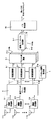
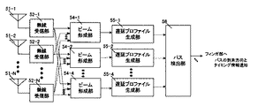
パスサーチ回路を備えた従来のアダプティブアレーアンテナ装置として、特開2001−345747号公報に開示されているものがある。図6は従来のアダプティブアレーを備えた直接拡散CDMA方式の受信装置の構成を示すブロック図である。以下、図6を用いて、その動作説明を行う。図6に示すn個のアンテナ素子51―1〜nで受信されたRF信号は、各アンテナ素子にそれぞれ無線受信部52―1〜nに送られる。各無線受信部52―1〜nでは、それぞれこれらのRF信号を中間周波数(IF帯)に周波数変換し、かつ図示しない自動利得増幅器で増幅する。
【0005】
さらに、図示しない直交検波器でI/Qチャネルのベースバンド信号に直交検波した後、図示しないA/D変換器でディジタル信号に変換して出力する。ビーム形成器54は、各アンテナ素子51―1〜nに受信されたベースバンド信号に対し、直接拡散CDMAの受信装置であるため、図示しない所望波信号の符号相関値処理出力に対して、互いに直交する複数の直交ビームウエイトを掛け合わせる。ビーム形成器54―1〜4 によりビームウエイトが乗算され、その後これらが合成されることで、各アンテナ素子51―1〜nの出力間の位相が補正される。
【0006】
これにより、ビーム形成器54−1〜4はそれぞれ1個のビームを生成して対応の遅延プロファイル推定部55―1〜4 へ出力することができる。各ビーム形成器54−1〜4から出力されるビームa〜dに基づき、遅延プロファイル推定部55―1〜4は遅延プロファイルを生成してパス検出回路56へ出力する。パス検出回路56は、ビーム毎の遅延プロファイルから有効なパスを検出してそのタイミングとビーム番号を図1に示す受信タイミング及びビーム番号をフィンガー部へ通知する。
【0007】
以上のような動作により、セルの1つのセクタを複数のビームに分けて通信させることが可能になり、かつ各ビームの通信信号に対する他のユーザからの干渉を減らすことが可能になり、干渉ユーザの影響を低減した後に、受信タイミング検出をすることで、その精度を向上することができる。
【0008】
【発明が解決しようとする課題】
しかしながら、上記構成を採る従来の受信装置では、複数の直交ビームウエイトによる指向性ビームの中間方向から、所望ユーザの電波が到来する場合、指向性利得が劣化し、干渉成分が十分に抑圧されない。このように、受信タイミング検出の精度に所望ユーザの電波の到来方向依存性が生じてしまうという課題があった。
【0009】
本発明はかかる点に鑑みてなされたものであり、アレーアンテナを備えたパスサーチ回路において、所望ユーザの電波のパス受信タイミング検出時における精度の方向依存性を低減する受信装置を提供することを目的とする。
【0010】
【課題を解決するための手段】
本発明のパスサーチ回路は、等間隔直線アレー形状の複数のアンテナ素子で構成されるアレーアンテナと、前記アレーアンテナの各アンテナ素子で受信された高周波信号を周波数変換後に直交検波する複数の無線受信部と、前記各無線受信部の出力に対し、互いに直交する複数の指向性ウエイトを乗算する直交マルチビーム形成部と、前記直交マルチビーム形成部の各出力と既知信号との相関演算を行う相関演算部と、前記各相関演算部の出力に実数ウエイトを乗算するウエイト乗算部と、前記ウエイト乗算部の出力信号から遅延プロファイルを生成する遅延プロファイル生成部と、前記遅延プロファイルから到来パスの受信タイミングと到来方向を検出するパス検出部とを具備し、前記直交マルチビーム形成部が、前記互いに直交する複数の指向性ウエイトとしてユニタリ行列を用いる構成を採る。
【0011】
【発明の実施の形態】
本発明の請求項1に記載の発明は、等間隔直線アレー形状の複数のアンテナ素子で構成されるアレーアンテナで受信された複数の高周波信号を、それぞれ複数の無線受信部で周波数変換後に直交検波することにより得られた複数のI/Qベースバンド信号を受信し、前記I/Qベースバンド信号に対して互いに直交する複数の指向性ウエイトを乗算する直交マルチビーム形成部と、前記直交マルチビーム形成部の各出力と予め決められた信号との相関演算を行う相関演算部と、前記各相関演算部の出力に実数ウエイトを乗算するウエイト乗算部と、前記ウエイト乗算部の出力信号から遅延プロファイルを生成する遅延プロファイル生成部と、前記遅延プロファイルから到来パスの受信タイミングと到来方向を検出するパス検出部とを具備し、前記直交マルチビーム形成部が、前記互いに直交する複数の指向性ウエイトとしてユニタリ行列を用いるパスサーチ回路であり、所望ユーザの電波のパス受信タイミング検出時における精度の方向依存性を低減できる作用を有する。
【0012】
本発明の請求項2に記載の発明は、各相関演算部の出力を受けて、前記出力のレベルを比較することで、予め決められた数の相関演算部の出力のみを選択して出力するビーム選択部を具備し、ウエイト乗算部は、前記ビーム選択部で選択された相関演算部の出力に対してのみ実数ウエイトを乗算する請求項1記載のパスサーチ回路であり、おおまかなパスの到来方向を推定し、パスが到来していない方向には遅延プロファイルを形成させないという作用を有する。
【0013】
本発明の請求項3に記載の発明は、等間隔直線アレー形状の複数のアンテナ素子で構成されるアレーアンテナで受信された複数の高周波信号を、それぞれ複数の無線受信部で周波数変換後に直交検波することにより得られた複数のI/Qベースバンド信号を受信し、前記I/Qベースバンド信号に対して予め決められた信号との相関演算を行う相関演算部と、前記各相関演算部の出力に互いに直交する複数の指向性ウエイトを乗算する直交マルチビーム形成部と、前記直交マルチビーム形成部の各出力に実数ウエイトを乗算するウエイト乗算部と、前記ウエイト乗算部の出力信号から遅延プロファイルを生成する遅延プロファイル生成部と、前記遅延プロファイルから到来パスの受信タイミングと到来方向を検出するパス検出部とを具備し、前記直交マルチビーム形成部が、前記互いに直交する複数の指向性ウエイトとしてユニタリ行列を用いるパスサーチ回路であり、所望ユーザの電波のパス受信タイミング検出時における精度の方向依存性を低減できる作用を有する。
【0014】
本発明の請求項4に記載の発明は、直交マルチビーム形成部の出力を受けて、前記出力のレベルを比較することで、予め決められた数の直交マルチビーム形成部の出力のみを選択して出力するビーム選択部を具備し、ウエイト乗算部は、前記ビーム選択部で選択された直交マルチビーム形成部の出力に対してのみ実数ウエイトを乗算する請求項3記載のパスサーチ回路であり、おおまかなパスの到来方向を推定し、パスが到来していない方向には遅延プロファイルを形成させないという作用を有する。
【0015】
本発明の請求項5に記載の発明は、主ビーム方向の相異なる指向性を形成する実数ウエイトを乗算する複数のウエイト乗算部と、前記複数のウエイト乗算部の出力信号からそれぞれ遅延プロファイルを生成する複数の遅延プロファイル生成部と、前記複数の遅延プロファイルを電力合成する遅延プロファイル電力合成部と、前記遅延プロファイル電力合成部の出力から到来パスの受信タイミングを検出するパス検出部とを具備する請求項1又は3記載のパスサーチ回路であり、複数の遅延プロファイルを電力合成した遅延プロファイルにより到来パスの受信タイミング検出性能を向上する作用を有する。
【0016】
本発明の請求項6に記載の発明は、方向の相異なる指向性を形成する実数ウエイトを乗算する複数のウエイト乗算部と、前記複数のウエイト乗算部の出力信号からそれぞれ遅延プロファイルを生成する複数の遅延プロファイル生成部と、前記複数の遅延プロファイルから受信タイミング毎に最大電力値を選択することで到来方向を検出するパス検出部とを具備する請求項1又は3記載のパスサーチ回路であり、複数の遅延プロファイルから受信タイミング毎の方向推定が可能となる作用を有する。
【0017】
本発明の請求項7に記載の発明は、主ビーム方向の相異なる指向性を形成する実数ウエイトを乗算する複数のウエイト乗算部と、前記複数のウエイト乗算部の出力信号からそれぞれ遅延プロファイルを生成する複数の遅延プロファイル生成部と、前記複数の遅延プロファイルから受信タイミング毎に最大電力値を選択することで到来方向を検出し、かつ、受信タイミング毎の前記最大電力値を基に生成した遅延プロファイルから到来パスの受信タイミングを検出するパス検出部とを具備する請求項1又は3記載のパスサーチ回路であり、複数の遅延プロファイルから到来パスの方向推定及び受信タイミング検出が可能となる作用を有する。
【0018】
本発明の請求項8に記載の発明は、主ビーム方向の相異なる指向性を形成する実数ウエイトを乗算する複数のウエイト乗算部と、前記複数のウエイト乗算部の出力信号からそれぞれ遅延プロファイルを生成する複数の遅延プロファイル生成部と、前記複数の遅延プロファイルを電力合成する遅延プロファイル電力合成部と、前記遅延プロファイル電力合成部の出力から到来パスの受信タイミングを検出し、前記各到来パスの受信タイミングでの前記複数のウエイト乗算部の出力を基に到来方向推定を行うことで、前記各到来パスの受信タイミングと到来方向を検出するパス検出部とを具備する請求項1又は3記載のパスサーチ回路であり、複数の遅延プロファイルから到来パスの方向推定及び受信タイミング検出が可能となる作用を有する。
【0019】
本発明の請求項9に記載の発明は、主ビーム方向の相異なる指向性を形成する実数ウエイトを乗算する複数のウエイト乗算部と、前記複数のウエイト乗算部の出力信号からそれぞれ遅延プロファイルを生成する複数の遅延プロファイル生成部と、前記複数の遅延プロファイルから、レイク合成に用いる最大フィンガ数を超える電力上位の到来パス受信タイミングを検出し、前記各到来パス受信タイミングでの前記複数のウエイト乗算部の出力を基に到来方向推定を行い、前記到来方向への指向性受信電力の高い順に最大フィンガ数以下の到来パスの受信タイミングと到来方向を検出するパス検出部とを具備する請求項1又は3記載のパスサーチ回路であり、複数の遅延プロファイルから到来パスの方向推定及び受信タイミング検出がより高精度に行えるという作用を有する。
【0020】
本発明の請求項10に記載の発明は、主ビーム方向の相異なる指向性を形成する実数ウエイトを乗算する複数のウエイト乗算部と、前記複数のウエイト乗算部の出力信号からそれぞれ遅延プロファイルを生成する複数の遅延プロファイル生成部と、前記複数の遅延プロファイルを電力合成する遅延プロファイル電力合成部と、前記遅延プロファイル電力合成部の出力から、レイク合成に用いる最大フィンガ数を超える電力上位の到来パス受信タイミングを検出し、前記各到来パス受信タイミングでの直交マルチビーム形成部の出力を基に到来方向推定を行い、前記到来方向への指向性受信電力の高い順に最大フィンガ数以下の到来パスの受信タイミングと到来方向を検出するパス検出部とを具備する請求項1又は3記載のパスサーチ回路であり、複数の遅延プロファイルから到来パスの方向推定及び受信タイミング検出がより高精度に行えるという作用を有する。
【0021】
本発明の請求項11に記載の発明は、パス検出部において検出された各到来パスの到来方向の角度広がりを算出する角度広がり算出部と、前記角度広がりが所定値よりも小さい場合は、前記到来パスの到来方向の平均値をすべてのパスの到来方向とする角度広がり判定部とを具備する請求項1又は3記載のパスサーチ回路であり、角度広がりに応じて到来パスの方向推定及び受信タイミング検出を適応的に切り替える作用を有する。
【0022】
本発明の請求項12に記載の発明は、直交マルチビーム形成部は、複数の無線受信部間の振幅位相ばらつきを補正する補正係数を乗算した直交マルチビームウエイトを用いて、直交マルチビームを形成する請求項1又は3記載のパスサーチ回路であり、理想に近いビーム形状を保つことができ、それに伴い、パスサーチ回路におけるパス検出精度の劣化を防ぐことができる作用を有する。
【0023】
本発明の請求項13に記載の発明は、直交マルチビーム形成部は、等間隔直線アレー形状のアレーアンテナを構成するアンテナ素子間の結合を補正する補正係数を乗算した直交マルチビームウエイトを用いて、直交マルチビームを形成する請求項1又は3記載のパスサーチ回路であり、理想に近いビーム形状を保つことができ、それに伴い、パスサーチ回路におけるパス検出精度の劣化を防ぐことができる作用を有する。
【0024】
本発明の請求項14に記載の発明は、遅延プロファイル生成部は、所定回数だけ生成される遅延プロファイルを平均化したものを出力する請求項1又は3記載のパスサーチ回路であり、パス変化の追従性は劣るが、ノイズの影響を低減することができ、より安定したパスサーチ動作が行える作用を有する。
【0025】
本発明の請求項15に記載の発明は、等間隔直線アレー形状の複数のアンテナ素子で構成されるアレーアンテナと、前記アレーアンテナの各アンテナ素子で受信された高周波信号を周波数変換後に直交検波して複数のI/Qベースバンド信号を出力する複数の無線受信部と、前記複数のI/Qベースバンド信号を受信し、前記I/Qベースバンド信号に対して互いに直交する複数の指向性ウエイトを乗算する直交マルチビーム形成部と、前記直交マルチビーム形成部の各出力と予め決められた信号との相関演算を行う相関演算部と、前記各相関演算部の出力に実数ウエイトを乗算するウエイト乗算部と、前記ウエイト乗算部の出力信号から遅延プロファイルを生成する遅延プロファイル生成部と、前記遅延プロファイルから到来パスの受信タイミングと到来方向を検出するパス検出部と、前記到来パスの受信タイミングで前記I/Qベースバンド信号からパスを分離するパス分離部と、分離された前記パス毎に前記到来パスの到来方向に指向性ビームを形成するパス受信ビーム生成部と、前記パス受信ビーム生成部の出力信号を合成して受信するパス合成部とを具備し、前記直交マルチビーム形成部が、前記互いに直交する複数の指向性ウエイトとしてユニタリ行列を用いる無線受信装置であり、パスサーチ結果であるパスタイミング及びパス方向情報に基づき、パス分離しパス方向に指向性を向けて受信することができる。これにより干渉波を低減することができ、高品質な通信ができる作用を有する。
【0026】
本発明の請求項16に記載の発明は、等間隔直線アレー形状の複数のアンテナ素子で構成されるアレーアンテナと、前記アレーアンテナの各アンテナ素子で受信された高周波信号を周波数変換後に直交検波して複数のI/Qベースバンド信号を出力する複数の無線受信部と、前記複数のI/Qベースバンド信号を受信し、前記I/Qベースバンド信号に対して予め決められた信号との相関演算を行う相関演算部と、前記各相関演算部の出力に互いに直交する複数の指向性ウエイトを乗算する直交マルチビーム形成部と、前記直交マルチビーム形成部の各出力にウエイトを乗算する実数ウエイト乗算部と、前記ウエイト乗算部の出力信号から遅延プロファイルを生成する遅延プロファイル生成部と、前記遅延プロファイルから到来パスの受信タイミングと到来方向を検出するパス検出部と、前記到来パスの受信タイミングで前記I/Qベースバンド信号からパスを分離するパス分離部と、分離された前記パス毎に前記到来パスの到来方向に指向性ビームを形成するパス受信ビーム生成部と、前記パス受信ビーム生成部の出力信号を合成して受信するパス合成部とを具備し、前記直交マルチビーム形成部が、前記互いに直交する複数の指向性ウエイトとしてユニタリ行列を用いる無線受信装置であり、パスサーチ結果であるパスタイミング及びパス方向情報に基づき、パス分離しパス方向に指向性を向けて受信することができる。これにより干渉波を低減することができ、高品質な通信ができる作用を有する。
【0027】
本発明の請求項17に記載の発明は、パス受信ビーム生成部が、前記遅延プロファイルから最大SNRを与えるパス到来方向に指向性ビームを形成する請求項15又は16記載の無線受信装置であり、パスサーチ結果であるパスタイミング及びパス方向情報に基づき、パス分離しパス方向に指向性を向けて受信することができる。これにより干渉波を低減することができ、高品質な通信が可能となる。
【0028】
本発明の請求項18に記載の発明は、パス受信ビーム生成部が、前記遅延プロファイルから最大受信電力を与えるパス到来方向に指向性ビームを形成する請求項15又は16記載の無線受信装置であり、パスサーチ結果であるパスタイミング及びパス方向情報に基づき、パス分離しパス方向に指向性を向けて受信することができる。これにより干渉波を低減することができ、高品質な通信が可能となる。
【0029】
本発明の請求項19に記載の発明は、等間隔直線アレー形状の複数のアンテナ素子で構成されるアレーアンテナと、前記アレーアンテナの各アンテナ素子で受信された高周波信号を周波数変換後に直交検波して複数のI/Qベースバンド信号を出力する複数の無線受信部と、前記複数のI/Qベースバンド信号を受信し、前記I/Qベースバンド信号に対して互いに直交する複数の指向性ウエイトを乗算する直交マルチビーム形成部と、前記直交マルチビーム形成部の各出力と予め決められた信号との相関演算を行う相関演算部と、前記各相関演算部の出力に実数ウエイトを乗算するウエイト乗算部と、前記ウエイト乗算部の出力信号から遅延プロファイルを生成する遅延プロファイル生成部と、前記遅延プロファイルから到来パスの受信タイミングと到来方向を検出するパス検出部と、前記到来パスの到来方向に、指向性ビームを形成して送信する指向性ビーム送信部を具備し、前記直交マルチビーム形成部が、前記互いに直交する複数の指向性ウエイトとしてユニタリ行列を用いる無線送信装置であり、パスサーチ結果であるパスタイミング及びパス方向情報に基づき、パス分離しパス方向に指向性を向けて送信することができる。これにより干渉波を低減することができ、高品質な通信が可能となる。
【0030】
本発明の請求項20に記載の発明は、等間隔直線アレー形状の複数のアンテナ素子で構成されるアレーアンテナと、前記アレーアンテナの各アンテナ素子で受信された高周波信号を周波数変換後に直交検波して複数のI/Qベースバンド信号を出力する複数の無線受信部と、前記複数のI/Qベースバンド信号を受信し、前記I/Qベースバンド信号に対して予め決められた信号との相関演算を行う相関演算部と、前記各相関演算部の出力に互いに直交する複数の指向性ウエイトを乗算する直交マルチビーム形成部と、前記直交マルチビーム形成部の各出力に実数ウエイトを乗算するウエイト乗算部と、前記ウエイト乗算部の出力信号から遅延プロファイルを生成する遅延プロファイル生成部と、前記遅延プロファイルから到来パスの受信タイミングと到来方向を検出するパス検出部と、前記到来パスの到来方向に、指向性ビームを形成して送信する指向性ビーム送信部を具備し、前記直交マルチビーム形成部が、前記互いに直交する複数の指向性ウエイトとしてユニタリ行列を用いる無線送信装置であり、パスサーチ結果であるパスタイミング及びパス方向情報に基づき、パス方向に指向性を向けて送信することができる。これにより干渉波を低減することができ、高品質な通信が可能となる。
【0031】
本発明の請求項21に記載の発明は、指向性ビーム送信部が、到来パスのうち最大受信電力のパス方向に指向性ビームを形成して送信する請求項19又は20記載の無線送信装置であり、パスサーチ結果であるパスタイミング及びパス方向情報に基づき、最大受信電力パス方向に指向性を向けて送信することができる。これにより干渉波を低減することができ、高品質な通信ができる作用を有する。
【0032】
本発明の請求項22に記載の発明は、指向性ビーム送信部が、到来パスのうち所定数の受信電力上位のパス方向に指向性ビームを形成して送信する請求項19又は20記載の無線送信装置であり、パスサーチ結果であるパスタイミング及びパス方向情報に基づき、受信電力上位のパス方向に指向性を向けて送信することができる。
【0033】
本発明の請求項23に記載の発明は、指向性ビーム送信部が、到来パスの平均到来パス方向に指向性ビームを形成して送信する請求項19又は20記載の無線送信装置であり、パスサーチ結果であるパスタイミング及びパス方向情報に基づき、平均到来パス方向に指向性を向けて送信することができる。
【0034】
以下、本発明の実施の形態について、図1から図7を用いて説明する。
【0035】
(実施の形態1)
図1は、本発明の実施の形態1に係るパスサーチ回路の構成を示すブロック図である。図1に示すパスサーチ回路において、アンテナ1−1〜Nにて受信された高周波信号は、各アンテナ1−1〜Nに設けられた無線受信部2−1〜Nにおいて、高周波増幅、周波数変換、直交検波およびA/D変換を順次施されたベースバンド信号3−1〜Nが生成され、直交マルチビーム形成部4に入力される。
【0036】
直交マルチビーム形成部4は、各アンテナ素子で得られたベースバンド信号3−1〜Nに、複素係数を乗算することで、互いに直交する複数(M個)のビームウエイトを乗算する。
【0037】
直交マルチビームの1つの例として、FFT(高速フーリエ変換)ビームがある。この場合のビームウエイトは、Wnmは(数1)で表すことができる。ここで、mはビームの番号(m=1〜M)、nはベースバンド信号3−nの番号(n=1〜N)、Mは生成するビーム数、Nはアンテナ素子数を表す。ここで、Mは、2以上N以下の値をとることができる。
【0038】
【数1】

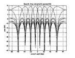
図2は、素子間隔0.5波長の8素子直線アレー時の直交ビームパターン(N=8、M=8)を示す。直交ビームパターンでは、各ビームの主ビーム方向に対し、その他のビームのヌルが向く。また、WmnをM行N列の行列Wにおける第m行n列の要素とすると、(数2)で示される性質を持つ。ここで、Hは複素共役転置、I(k)はk次の単位行列を示す。以下では、Wを直交ビーム生成行列と呼ぶ。
【0040】
【数2】
ここでサンプリング時刻kTにおけるn番目のベースバンド信号3−nをxn(k)と表すと、直交マルチビーム形成部4の出力であるm番目のビームで受信されたマルチビーム信号5−mは(数3)で表すことができる。ここで、Tはサンプリング間隔、*は複素共役を示す。(ただしn=1〜N)
【0042】
【数3】
相関演算部6―1〜Mの各々には、マルチビーム信号5−1〜Mがそれぞれ入力される。パイロット信号発生部7は受信信号にあらかじめ埋め込まれた既知信号(以下パイロット信号)を生成する。相関演算部6―1〜Mはパイロット信号との相関演算を行う。例えば、CDMA通信方式の場合には、スクランブリング符号と、拡散符号を用いて逆拡散処理後に、パイロット信号との相関演算を行う。また、TDMA通信方式の場合には、マルチビーム信号とパイロット信号との相関演算を行う。
【0044】
ここで、パイロット信号をr(s)とする。ここで、s=1〜Np。ただし、Npはパイロット信号のシンボル数とする。第m番目の相関演算部6−mは、マルチビーム信号5−mに対し、(数4)に示す相関演算を、パスサーチを行う時間範囲内のサンプル数Tsに相当する回数だけ、相関演算を開始するサンプル時間pを変化させながら行う。ここで、p=1〜Ts、Noはシンボルに対するオーバサンプル数である。なお、*は複素共役を示す。
【0045】
【数4】
ウエイト乗算部8―1〜Nbは、相関演算部6−1〜Mを入力とし、それぞれ異なるウエイトベクトルを乗算する。ここで、相関演算部6―1〜Mで得られたサンプル時間pを相関演算の開始点とする相関演算値を相関演算値ベクトルh(p)=[h1(p) h2(p)...hm(p)]Tで表すと、第k番目のウエイト乗算部8−kは、複素係数からなるウエイトベクトルu(θk)を相関演算値ベクトルに(数5)で示されるように乗算する。なお、k=1〜Nb、Tはベクトル転置を示す。
【0047】
【数5】
![]()
ここで、ウエイトベクトルu(θ)は、N素子のアレーアンテナにおいてθ方向に主ビームが向く指向性ビームウエイトベクトルa(θ)とすると、直交ビーム生成行列Wを用いて(数6)のようにして得られる。
【0049】
【数6】
![]()
N素子のアレーアンテナにおいてθ方向に主ビームが向く指向性ビームウエイトベクトルa(θ)は、例えば、(数7)のように表すことができる。ここで、λはキャリア波長、dは素子間隔である。
【0051】
【数7】
遅延プロファイル生成部9―1〜Nbは、それぞれウエイト乗算部8−1〜Nbで得られたy(p、θk)を基に遅延プロファイルを生成する。ここで、p=1〜Ts、k=1〜Nbである。遅延プロファイルは、p=1〜Nbのy(p、θk)の絶対値あるいは2乗を取ることで、各タイミングにおけるパス電力に比例した値が求まる。第k番目の遅延プロファイル生成部9―kは、(数2)の性質から、θk方向に主ビームを向けた場合のウエイトa(θk)で得られる遅延プロファイルと等価であることから、無線基地局装置がカバーすべき角度範囲内で、各θk範囲が定まる。また、その角度間隔は、必要とされるパスの到来角度分解能から定めることができる。アレー素子数が多くなるほど、パスの分解能が高まるため、各θkの角度間隔を狭めるで、より精度の高いパスサーチが可能となる。
【0053】
パス検出部10は、遅延プロファイル生成部9−1〜Nbから得られる各θk方向の遅延プロファイルから、例えばレイク合成に用いる最大フィンガ数を所定数L個とする電力上位パスを選択し、選択されたパスのタイミングと到来方向情報を出力する。
【0054】
パス検出部10の別な動作は、各θk方向の遅延プロファイル毎に、所定数の電力上位パスを信号とみなし、それ以外のパスを雑音とみなすことで、信号対雑音電力比(SIR)を算出する。全方向でのSIR算出後に、最大SIRを与える方向を到来パス方向とし、その方向の所定数L個の電力上位パスタイミングを到来パスのタイミング情報として出力する。
【0055】
パス検出部10の別な動作は、各θk方向の遅延プロファイル毎に、所定数L個の電力上位パスを信号とみなし、それらのパスの受信信号総電力を算出する。全方向で受信信号総電力の算出後に、最大の受信信号総電力が得られる方向を到来パス方向とし、その方向の所定数L個の電力上位パスタイミングを到来パスのタイミング情報として出力する。
【0056】
パス検出部10の別な動作は、(数8)に示すようにNb個の遅延プロファイルを電力合成した電力遅延プロファイルz(p)を用いて、所定数L個の電力上位パスを選択することで、パスのタイミングpsを決定し、その後に、(数9)に示すように選択されたパスタイミングpsで、Nb個の遅延プロファイルから受信電力値|y(ps、θk)|2が最大となる最大パス方向D(ps)を決定することで、到来パスのパスタイミングpsと到来方向情報D(ps)を出力する。ここで、p=1〜Ts、s=1〜L、k=1〜Nbである。
【0057】
なお、ここではNb個のすべての遅延プロファイルを電力合成する例を示したが、十分な到来角度分解能が得られる数の遅延プロファイルを用いる場合(例えば各θkの間隔が1°の場合)、以下の方法を用いてもよい。1段階目に、一部の遅延プロファイルを用いて(例えば、θkの間隔が10°程度となるものを用いる)、電力合成を行い、所定数L個の電力上位パスを選択し、パスのタイミングpsを決定する。2段階目で、決定されたパスタイミングpsのみで最大パス方向D(ps)を検出する方法でもよく、この場合、2段階目の方向推定時において、選択されたパスタイミングps以外のy(p、θk)の算出が不要となるため、パスサーチ性能劣化を抑えた上で、大幅な演算量の低減が可能となる。
【0058】
【数8】
【数9】
また、同様に、十分な到来角度分解能が得られる数の遅延プロファイルを用いる場合(例えば各θkの間隔が1°の場合)、以下の方法を用いていもよい。1段階目に、一部の遅延プロファイルを用いて(例えば、θkの間隔が10°程度となるものを用いる)、電力合成を行い、所定数L個を超える電力上位パスQ個を選択し、パスのタイミングpsを決定する。ここで、s=1〜Qである。2段階目で、決定されたパスタイミングpsのみで最大パス方向D(ps)を検出し、得られた最大パス方向の受信電力値|y(ps、D(ps))|2を用いて、再度、所定数L個の電力上位パスを選択する方法でもよく、この場合、処理量は若干増加するが、正しく到来方向指向性受信した場合のパス受信電力を用いてパスサーチを行うことができパスサーチ性能が向上する。
【0061】
パス検出部10の別な動作は、(数10)に示すようにNb個の遅延プロファイルから、各受信タイミングpでの最大電力方向D(p)を検出し、その後、(数11)で示される最大電力方向D(p)で得られる遅延プロファイルz(p)を用いて、所定数L個の電力上位パスを選択することで、パスのタイミングpsを決定する。以上の動作から到来パスのパスタイミングpsと到来方向情報D(ps)を出力する。ここで、p=1〜Ts、s=1〜Lである。
【0062】
【数10】
【数11】
なお、ここではNb個のすべての遅延プロファイルから最大電力方向を検出する例を示したが、十分な到来角度分解能が得られる数の遅延プロファイルを用いる場合(例えば各θkの間隔が1°の場合)、以下の方法を用いていもよい。1段階目に、一部の遅延プロファイルを用いて(例えば、θkの間隔が10°程度となるものを用いる)、各受信タイミングpでの最大電力方向D(p)を検出し、大まかな最大電力方向を検出し、その後、(数11)で示される最大電力方向D(p)で得られる遅延プロファイルz(p)を用いて、所定数L個の電力上位パスを選択し、パスのタイミングpsを決定する。2段階目に大まかな最大電力方向の精度を高めて方向推定する方法でもよく、この場合、2段階目の方向推定時において、選択されたパスタイミングps以外、及び最大電力方向周辺以外のy(p、θk)の算出が不要となるため、パスサーチ性能劣化を抑えた上で、大幅な演算量の低減が可能となる。
【0065】
また、同様に、十分な到来角度分解能が得られる数の遅延プロファイルを用いる場合(例えば各θkの間隔が1°の場合)、以下の方法を用いてもよい。1段階目に、一部の遅延プロファイルを用いて(例えば、θkの間隔が10°程度となるものを用いる)、各受信タイミングpでの最大電力方向D(p)を検出し、大まかな最大電力方向を検出し、その後、(数11)で示される最大電力方向D(p)で得られる遅延プロファイルz(p)を用いて、所定数L個を超える電力上位パスQ個を選択し、パスのタイミングpsを決定する。ここで、s=1〜Qである。2段階目に、Q個の大まかな最大電力方向の精度を高めて、最大パス方向D(ps)を検出し、得られた最大パス方向の受信電力値|y(ps、D(ps))|2を用いて、再度、所定数L個の電力上位パスを選択する方法でもよく、この場合、処理量は若干増加するが、正しく到来方向指向性受信した場合のパス受信電力を用いてパスサーチを行うことができパスサーチ性能が向上する。
【0066】
パス検出部10の別な動作は、前述したパス検出部を適応的に切り替える動作である。すなわち、各到来パスの到来方向の角度広がりを算出する角度広がり算出結果に応じて、動作を切り替える。一つの例は、パス検出部において検出された各到来パスの到来方向の角度広がりを算出し、角度広がりが所定値よりも小さい場合は、到来パスの到来方向の平均値をすべてのパスの到来方向とする、これにより角度広がりに応じて到来パスの方向推定及び受信タイミング検出を適応的に切り替えることが可能となる。
【0067】
以上のように、本実施の形態により、相関演算部における相関演算値を基に指向性毎の遅延プロファイルを生成することができ、さらにその空間的な分解能は、相関演算部の後段にあるウエイト乗算部の数を増加させることで、任意に設定することができる。この方法は、無線受信部の後段での指向性ビーム数を増加させ、そのビーム数に対応して、相関演算を行い、さらにその後に遅延プロファイルを算出するよりも、演算量的に少なく、ハードウエアの規模をいたずらに増加させる必要がない。
【0068】
これにより、指向性ビームを用いてパスサーチする場合でも、パスの到来方向の依存性を低減させることができ、どの方向からパスが到来しても、精度よくパスの方向およびタイミングを検出することができる。
【0069】
また、アレーアンテナが等間隔直線アレー形状である場合、アイトリプルイー・トランザクション・シグナル・プロシーディング、43巻5号1232頁(1995年) (IEEE Trans.Signal Processing,vol.43,No.5,pp.1232(1995))に掲載されているように、方位θに対するアレーアンテナの複素応答を表すステアリングベクトルa2(θ)の位相の共役中心対称性を用いて、(数12)に示すようにN次正方行列であるユニタリ行列QNを用いてステアリングベクトルを実数化する手法が適応できる。なお、a2(θ)は位相中心をアレー中心においた場合のステアリングベクトルである。b(θ)は実数化されたステアリングベクトルであり、(数14)のように示すことができる。また、QNは(数13)に示すように表され、(数2)の性質を満たす。よって、直交マルチビーム形成部4において、直交ビーム生成行列WとしてQNを用い、ウエイト乗算部8―1〜Nbにおいて、ウエイトベクトルu(θ)としてb(θ)を用いることで、ウエイト乗算部における乗算処理を複素乗算から実数乗算にすることができ、処理量を約半減できるという効果が得られる。ここで、dはアンテナ素子間隔、λはキャリア周波数の波長である。
【0070】
【数12】
![]()
【数13】
【数14】
また、直交マルチビーム形成部4において生成するビーム数はアレー素子数よりも、小さい数のビーム数に設定することができる。この際には、パスサーチの精度劣化を抑えた上に、相関演算部の数、ウエイト乗算部における乗算回数を低減でき、回路規模を低減することができる。
【0074】
なお、遅延プロファイル生成部は、生成される遅延プロファイルを所定回数にわたり平均化したものを出力してもよい。この場合、パス変化の追従性は劣るが、ノイズの影響を低減することができ、より安定したパスサーチ動作が行える。
【0075】
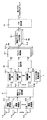
(実施の形態2)
図3は実施の形態2におけるパスサーチ回路の構成を示すブロック図である。実施の形態1と異なる部分は、相関演算部6―1〜Mの出力を選択するビーム選択部20が追加され、その出力を基にウエイト乗算部8−1〜Nbにおいてウエイト乗算を行う点である。以下、実施の形態1と異なる部分を主に説明する。 アンテナ1−1〜Nにて受信された高周波信号は、各アンテナ1−1〜Nに設けられた無線受信部2−1〜Nにおいて、高周波増幅、周波数変換、直交検波およびA/D変換を順次施されたベースバンド信号3−1〜Nが生成され、直交マルチビーム形成部4において入力される。直交マルチビーム形成部4は、各アンテナ素子で得られたベースバンド信号3−1〜Nに、複素係数を乗算することで、互いに直交する複数(M個)のビームウエイトを乗算する。
【0076】
相関演算部6―1〜Mの各々には、マルチビーム信号5−1〜Mがそれぞれ入力される。パイロット信号発生部7は受信信号にあらかじめ埋め込まれた既知信号(以下パイロット信号)を生成する。相関演算部6―1〜Mはパイロット信号との相関演算を行う。
【0077】
ここで、パイロット信号をr(s)とする。ここで、s=1〜Np。ただし、Npはパイロット信号のシンボル数とする。第m番目の相関演算部6−mは、マルチビーム信号5−mに対し、(数4)に示す相関演算を、パスサーチを行う時間範囲内のサンプル数Tsに相当する回数だけ、相関演算を開始するサンプル時間pを変化させながら行う。ここで、p=1〜Tsである。
【0078】
ビーム選択部20は、M個の相関演算部6−1〜Mの出力から、最大電力あるいは最大SIRが得られるマルチビーム信号と、それに隣接するマルチビーム信号を選択し出力する。
【0079】
ウエイト乗算部8―1〜Nbは、ビーム選択20での選択ビームに応じて生成される直交ビーム部分行列を用いて、選択された相関ベクトル値にウエイト乗算を行う。この場合、ビーム選択20での選択ビーム番号がMoで、選択する隣接ビーム数がcの場合、直交ビーム生成行列Wの(Mo−c)行から(Mo+c)行を取り出した(2×C+1)行N列の直交ビーム部分行列Wsを用いて、第k番目のウエイト乗算部8−kは、(数15)に示されるウエイトベクトルus(θ)を用いて、(数16)に示すようにウエイト乗算を行う。なお、k=1〜Nbとする。
【0080】
Hは複素共役転地を示す。また、θkが選択ビーム方向の範囲外にある場合、ウエイト乗算を行わない構成としてもよい。この場合、ウエイト乗算回数を低減でき、回路規模の低減が可能となる。また、選択ビーム番号がc以下の場合、最大ビーム番号Mo=c+1とする。同様に選択ビーム番号が(Mo−c)より大きい場合、Mo=Mo−cとする。
【0081】
【数15】
【数16】
ここで、hs(p)は、相関演算部6―1〜Mで得られたサンプル時間pを相関演算の開始点とする相関演算値を相関演算値ベクトルh(p)=[h1(p)h2(p)...hm(p)]Tの第(Mo−c)要素から第(Mo+c)要素を取り出したサブベクトルである。
【0084】
遅延プロファイル生成部9―1〜Nbは、それぞれウエイト乗算部8−1〜Nbで得られたy(p、θk)を基に遅延プロファイルを生成する。ここで、p=1〜Ts、k=1〜Nbである。遅延プロファイルは、p=1〜Nbのy(p、θk)の絶対値あるいは2乗を取ることで、各タイミングにおけるパス電力に比例した値が求まる。第k番目の遅延プロファイル生成部9−kは、(数2)の性質から、θk方向に主ビームを向けた場合のウエイトa(θk)で得られる遅延プロファイルと等価であることから、無線基地局装置がカバーすべき角度範囲内で、各θk範囲が定まる。また、その角度間隔は、必要とされるパスの到来角度分解能から定めることができる。アレー素子数が多くなるほど、パスの分解能が高まるため、各θkの角度間隔を狭めことで、より精度の高いパスサーチが可能となる。
【0085】
パス検出部10は、実施の形態1で説明した同様の動作によりパスのタイミングと到来方向情報を出力する。ここでは説明は省略する。
【0086】
以上のように、本実施の形態により、ビーム選択部において、直交マルチビーム形成部4での指向性受信で得られる信号から、あらかじめ大まかなパスの到来方向を検知することができ、その後のウエイト乗算部では、大まかなパス方向の周辺範囲で、指向性ビームでの遅延プロファイルを検出することができ、方向推定精度を向上させたパスサーチが可能となる。また、指向性ビームが到来パス方向に正しくむけて得られる遅延プロファイルを基にパス到来タイミングを検出することで、パスサーチ精度を向上させるができる。アレーアンテナの設置場所が十分高い場所にある場合、到来パスの角度広がりは10度程度内であることが実験的に報告されており、本実施の形態では、おおまかなパスの到来方向を推定し、パスが到来していない方向には遅延プロファイルを形成させない動作が可能であり、本実施の形態の適用が特に有効である。
【0087】
また、本実施の形態は、相関演算部における相関演算値を基に指向性毎の遅延プロファイルを生成することができ、さらにその空間的な分解能は、相関演算部の後段にあるウエイト乗算部の数を増加させることで、任意に設定することができる。この方法は、無線受信部の後段での指向性ビーム数を増加させ、そのビーム数に対応して、相関演算を行い、その後に遅延プロファイルを算出するよりも、演算量的に少なく、ハードウエアの規模をいたずらに増加させる必要がない。
【0088】
なお、遅延プロファイル生成部は、生成される遅延プロファイルを所定回数にわたり平均化したものを出力してもよい。この場合、パス変化の追従性は劣るが、ノイズの影響を低減することができ、より安定したパスサーチ動作が行える。
【0089】
(実施の形態3)
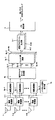
図4は、本発明の実施の形態3に係るパスサーチ回路の構成を示すブロック図である。実施の形態1と異なる部分は、無線受信部2−1〜Nの出力である各ベースバンド信号に対し、パイロット信号と相関演算を行う相関演算部6b−1〜Nを設け、その相関演算値出力に対し直交マルチビーム形成部4b、ウエイト乗算部8b−1〜Nbを設けている点である。以下、実施の形態1と異なる部分を主に説明する。
【0090】
図4に示すパスサーチ回路において、アンテナ1−1〜Nにて受信された高周波信号は、各アンテナ1−1〜Nに設けられた無線受信部2−1〜Nにおいて、高周波増幅、周波数変換、直交検波およびA/D変換を順次施されたベースバンド信号3−1〜Nが生成され、N個の相関演算部6b−1〜Nに入力される。
【0091】
相関演算部6b―1〜Nの各々には、ベースバンド信号3−1〜Nがそれぞれ入力される。パイロット信号発生部7bは受信信号にあらかじめ埋め込まれた既知信号(以下パイロット信号)を生成する。相関演算部6b―1〜Nはパイロット信号との相関演算を行う。例えば、CDMA通信方式の場合には、スクランブリング符号と、拡散符号を用いて逆拡散処理後に、パイロット信号との相関演算を行う。また、TDMA通信方式の場合には、ベースバンド信号とパイロット信号との相関演算を行う。
【0092】
ここでサンプリング時刻kTにおけるn番目のベースバンド信号3−nをxn(k)、パイロット信号をr(s)とする。ここで、s=1〜Np。ただし、Npはパイロット信号のシンボル数とする。第n番目の相関演算部6b−nは、ベースバンド信号3−nに対し、(数17)に示す相関演算を、パスサーチを行う時間範囲内のサンプル数Tsに相当する回数だけ、相関演算を開始するサンプル時間pを変化させながら行う。ここで、p=1〜Ts、Noはシンボルに対するオーバサンプル数である。なお、*は複素共役を示す。
【0093】
【数17】
直交マルチビーム形成部4bは、各アンテナ素子で得られたベースバンド信号3−1〜Nに、複素係数を乗算することで、互いに直交する複数(M個)のビームウエイトを乗算する。
【0095】
直交マルチビームの1つの例として、実施の形態1で説明したように例えばFFT(高速フーリエ変換)ビームがある。この場合の直交ビーム生成行列Wは、(数1)のように表すことができる。
【0096】
ここでサンプリング時刻pにおけるn番目の相関演算部6b−nの出力をhn(p)と表すと、直交マルチビーム形成部4bの出力であるm番目のビームで受信されたマルチビーム信号5b−mは(数18)で表すことができる。ここで、p=1〜Ts、*は複素共役を示す。(ただしn=1〜N)
【0097】
【数18】
ウエイト乗算部8b―1〜Nbは、直交マルチビーム形成部4bで得られるマルチビーム信号5b−1〜Mを入力とし、それぞれ異なるウエイトベクトルを乗算する。ここで、マルチビーム信号5b−1〜Mのサンプル時刻pの出力をマルチビーム信号ベクトルB(p)=[B1(p) B2(p)...Bm(p)]Tで表すと、第k番目のウエイト乗算部8b−kは、複素係数からなるウエイトベクトルu(θk)を相関演算値ベクトルに(数19)で示されるように乗算する。なお、k=1〜Nb、Hは共役転置を示す。
【0099】
【数19】
ここで、ウエイトベクトルu(θ)は、N素子のアレーアンテナにおいてθ方向に主ビームが向く指向性ビームウエイトベクトルa(θ)とすると、直交ビーム生成行列Wを用いて(数6)のようにして得られる。
【0101】
遅延プロファイル生成部9―1〜Nbは、それぞれウエイト乗算部8b−1〜Nbで得られたy(p、θk)を基に遅延プロファイルを生成する。ここで、p=1〜Ts、k=1〜Nbである。遅延プロファイルは、p=1〜Nbのy(p、θk)の絶対値あるいは2乗を取ることで、各タイミングにおけるパス電力に比例した値が求まる。第k番目の遅延プロファイル生成部9―kは、(数2)の性質から、θk方向に主ビームを向けた場合のウエイトa(θk)で得られる遅延プロファイルと等価であることから、無線基地局装置がカバーすべき角度範囲内で、各θk範囲が定まる。また、その角度間隔は、必要とされるパスの到来角度分解能から定めることができる。アレー素子数が多くなるほど、パスの分解能が高まるため、各θkの角度間隔を狭めるで、より精度の高いパスサーチが可能となる。
【0102】
パス検出部10は、遅延プロファイル生成部9−1〜Nbから得られる各θk方向の遅延プロファイルから、例えばレイク合成に用いる最大フィンガ数を所定数とする電力上位パスを選択し、選択されたパスのタイミングと到来方向情報を出力する。
【0103】
パス検出部10は、実施の形態1で説明した同様の動作によりパスのタイミングと到来方向情報を出力する。ここでは説明は省略する。
【0104】
以上のように、本実施の形態により、相関演算部における相関演算値を基に指向性毎の遅延プロファイルを生成することができ、さらにその空間的な分解能は、相関演算部の後段にあるウエイト乗算部の数を増加させることで、任意に設定することができる。この方法は、無線受信部の後段での指向性ビーム数を増加させ、そのビーム数に対応して、相関演算を行い、さらにその後に遅延プロファイルを算出するよりも、演算量的に少なく、ハードウエアの規模をいたずらに増加させる必要がない。
【0105】
これにより、指向性ビームを用いてパスサーチする場合でも、パスの到来方向の依存性を低減させることができ、どの方向からパスが到来しても、精度よくパスの方向およびタイミングを検出することができる。
【0106】
また、アレーアンテナが等間隔直線アレー形状である場合、実施の形態1で説明したように、方位θに対するアレーアンテナの複素応答を表すステアリングベクトルa2(θ)の位相の共役中心対称性を用いて、(数12)に示すようにN次正方行列であるユニタリ行列QNを用いてステアリングベクトルを実数化する手法が適応できる。この場合、直交マルチビーム形成部4bにおいて、直交ビーム生成行列Wとして(数13)で示されるQNを用い、ウエイト乗算部8b―1〜Nbにおいて、ウエイトベクトルu(θ)として(数14)で示されるb(θ)を用いることで、ウエイト乗算部における乗算処理を複素乗算から実数乗算にすることができ、処理量を約半減できるという効果が得られる。
【0107】
また、直交マルチビーム形成部4において生成するビーム数はアレー素子数よりも、小さい数のビーム数に設定することができる。この際には、パスサーチの精度劣化を抑えた上に、相関演算部の数、ウエイト乗算部における乗算回数を低減でき、回路規模を低減することができる。
【0108】
なお、遅延プロファイル生成部は、生成される遅延プロファイルを所定回数にわたり平均化したものを出力してもよい。この場合、パス変化の追従性は劣るが、ノイズの影響を低減することができ、より安定したパスサーチ動作が行える。
【0109】
(実施の形態4)
図5は実施の形態4におけるパスサーチ回路の構成を示すブロック図である。本実施の形態は、実施の形態3の別な構成を示す。実施の形態3と異なる部分は、直交マルチビーム形成部4bで得られるマルチビーム信号相5b―1〜Mの出力を選択するビーム選択部20bが追加され、その出力を基にウエイト乗算部8−1〜Nbにおいてウエイト乗算を行う点である。以下、実施の形態1と異なる部分を主に説明する。
【0110】
図5に示すパスサーチ回路において、アンテナ1−1〜Nにて受信された高周波信号は、各アンテナ1−1〜Nに設けられた無線受信部2−1〜Nにおいて、高周波増幅、周波数変換、直交検波およびA/D変換を順次施されたベースバンド信号3−1〜Nが生成され、N個の相関演算部6b−1〜Nに入力される。
【0111】
相関演算部6b―1〜Nの各々には、ベースバンド信号3−1〜Nがそれぞれ入力される。パイロット信号発生部7bは受信信号にあらかじめ埋め込まれた既知信号(以下パイロット信号)を生成する。相関演算部6b―1〜Nはパイロット信号との相関演算を行う。
【0112】
ここでサンプリング時刻kTにおけるn番目のベースバンド信号3−nをxn(k)、パイロット信号をr(s)とする。ここで、s=1〜Np。ただし、Npはパイロット信号のシンボル数とする。第n番目の相関演算部6b−nは、ベースバンド信号3−nに対し、(数17)に示す相関演算を、パスサーチを行う時間範囲内のサンプル数Tsに相当する回数だけ、相関演算を開始するサンプル時間pを変化させながら行う。
【0113】
直交マルチビーム形成部4bは、各アンテナ素子で得られたベースバンド信号3−1〜Nに、複素係数を乗算することで、互いに直交する複数(M個)のビームウエイトを乗算する。
【0114】
直交マルチビームの1つの例として、実施の形態1で説明したように例えばFFT(高速フーリエ変換)ビームがある。この場合の直交ビーム生成行列Wは、(数1)のようにで表すことができる。
【0115】
ここでサンプリング時刻pにおけるn番目の相関演算部6b−nの出力をhn(p)と表すと、直交マルチビーム形成部4bの出力であるm番目のビームで受信されたマルチビーム信号5b−mは(数18)で表すことができる。
【0116】
ビーム選択部20は、M個の相関演算部6−1〜Mの出力から、最大電力あるいは最大SIRが得られるマルチビーム信号と、それに隣接するマルチビーム信号を選択し出力する。
【0117】
ウエイト乗算部8b―1〜Nbは、ビーム選択20bでの選択ビームに応じて生成される直交ビーム部分行列を用いて、選択された相関ベクトル値にウエイト乗算を行う。この場合、ビーム選択20bでの選択ビーム番号がMoで、選択する隣接ビーム数がcの場合、直交ビーム生成行列Wの(Mo−c)行から(Mo+c)行を取り出した(2×C+1)行N列の直交ビーム部分行列Wsを用いて、第k番目のウエイト乗算部8−kは、(数15)に示されるウエイトベクトルus(θ)を用いて、(数20)に示すようにウエイト乗算を行う。なお、k=1〜Nb。Hは複素共役転地を示す。また、θkが選択ビーム方向の範囲外にある場合、ウエイト乗算を行わない構成としてもよい。この場合、ウエイト乗算回数を低減でき、回路規模の低減が可能となる。また、選択ビーム番号がc以下の場合、最大ビーム番号Mo=c+1とする。同様に選択ビーム番号が(Mo−c)より大きい場合、Mo=Mo−cとする。
【0118】
【数20】
ここで、Bs(p)は、直交マルチビーム形成部4bで得られたマルチビーム信号5b−1〜Mのサンプル時刻pの出力をマルチビーム信号ベクトルB(p)=[B1(p)B2(p)...Bm(p)]Tで表した場合の第(Mo−c)要素から第(Mo+c)要素を取り出したサブベクトルである。
【0120】
遅延プロファイル生成部9―1〜Nbは、それぞれウエイト乗算部8b−1〜Nbで得られたy(p、θk)を基に遅延プロファイルを生成する。ここで、p=1〜Ts、k=1〜Nbである。遅延プロファイルは、p=1〜Nbのy(p、θk)の絶対値あるいは2乗を取ることで、各タイミングにおけるパス電力に比例した値が求まる。第k番目の遅延プロファイル生成部9−kは、(数2)の性質から、θk方向に主ビームを向けた場合のウエイトa(θk)で得られる遅延プロファイルと等価であることから、無線基地局装置がカバーすべき角度範囲内で、各θk範囲が定まる。また、その角度間隔は、必要とされるパスの到来角度分解能から定めることができる。アレー素子数が多くなるほど、パスの分解能が高まるため、各θkの角度間隔を狭めことで、より精度の高いパスサーチが可能となる。
【0121】
パス検出部10は、実施の形態1で説明した同様の動作によりパスのタイミングと到来方向情報を出力する。ここでは説明は省略する。
【0122】
以上のように、本実施の形態により、ビーム選択部において、直交マルチビーム形成部4bでの指向性受信で得られる信号から、あらかじめ大まかなパスの到来方向を検知することができ、その後のウエイト乗算部では、大まかなパス方向の周辺範囲で、指向性ビームでの遅延プロファイルを検出することができ、方向推定精度を向上させたパスサーチが可能となる。また、指向性ビームが到来パス方向に正しくむけて得られる遅延プロファイルを基にパス到来タイミングを検出することで、パスサーチ精度を向上させるができる。アレーアンテナの設置場所が十分高い場所にある場合、到来パスの角度広がりは10度程度内であることが実験的に報告されており、本実施の形態では、おおまかなパスの到来方向を推定し、パスが到来していない方向には遅延プロファイルを形成させない動作が可能であり、本実施の形態の適用が特に有効である。
【0123】
また、本実施の形態は、相関演算部における相関演算値を基に指向性毎の遅延プロファイルを生成することができ、さらにその空間的な分解能は、相関演算部の後段にあるウエイト乗算部の数を増加させることで、任意に設定することができる。この方法は、無線受信部の後段での指向性ビーム数を増加させ、そのビーム数に対応して、相関演算を行い、その後に遅延プロファイルを算出するよりも、演算量的に少なく、ハードウエアの規模をいたずらに増加させる必要がない。
【0124】
なお、遅延プロファイル生成部は、生成される遅延プロファイルを所定回数にわたり平均化したものを出力してもよい。この場合、パス変化の追従性は劣るが、ノイズの影響を低減することができ、より安定したパスサーチ動作が行える。
【0125】
(実施の形態5)
図6は実施の形態1におけるパスサーチ回路の別な構成を示すブロック図である。実施の形態1と異なる部分は、アレー素子間結合および無線受信部間の位相振幅のばらつきを補正する補正行列生成部30が追加され、直交マルチビーム形成部4にその補正行列Wcが入力されている点である。以下、実施の形態1と異なる部分を主に説明する。
【0126】
アンテナ1−1〜Nにて受信された高周波信号は、各アンテナ1−1〜Nに設けられた無線受信部2−1〜Nにおいて、高周波増幅、周波数変換、直交検波およびA/D変換を順次施されたベースバンド信号3−1〜Nが生成され、直交マルチビーム形成部4において入力される。
【0127】
補正行列生成部30は、アレー素子間結合および無線受信部間の位相振幅のばらつきを補正する行列を生成する。アレー素子間結合を行うN次の補正行列C1の生成は、電波暗室内でアレーアンテナ部のみの特性を測定することで得られる。詳細は、文献Wirel Pers Commun Emerg Technol Enhanc Commun p.259-268(1999)に開示されているので、ここではその詳細説明は省略する。無線受信部の位相振幅ばらつきの補正方法は、例えば、特開2001−86049号公報に開示されている。これは、無線受信部の前段にカプラを介して、キャリブレーション信号を重畳し、基準となるベースバンド信号(例えば3−1)に対する他のベースバンド信号(3−k)、ただし、k=2〜Nの位相差φkと振幅差Akを周期的に算出することで得られる。これらの位相差と振幅差を複素数値で表した場合の複素共役値が補正値となる。N次の行列C2として表現した場合は、(数21)であらわすことができる。
【0128】
【数21】
直交マルチビーム形成部4は、補正行列生成部30で得られた補正行列Wcを直交ビーム行列Wに乗算して補正を加えた後に、各アンテナ素子で得られたベースバンド信号3−1〜Nに、補正を加えた複素係数を乗算することで、互いに直交する複数(M個)のビームウエイトを乗算する。この場合、補正を加えた直交ビーム行列W2は(数22)で表すことができる。
【0130】
【数22】
以降の動作は、実施の形態1と同様であるので以下は省略する。
【0132】
以上のように、本実施の形態により、実施の形態1の効果に加え、アレー素子間結合および無線受信部間の位相振幅のばらつきを補正する補正行列生成部30が追加され、直交マルチビーム形成部4にその補正行列Wcを乗算することで、理想に近いビーム形状を保つことができ、それに伴い、パスサーチ回路におけるパス検出精度の劣化を防ぐことができる。
【0133】
なお、本実施の形態では、アレー素子間結合と、無線受信部間の位相振幅のばらつきを同時に補正する方法で説明したが、いずれか一方の場合でもよい。すなわち、C1、C2のいずれかがN次の単位行列とみなして同様な処理が適用できる。
【0134】
また、本実施の形態では、実施の形態1に補正行列生成部30を付加する構成について説明したが、他の実施の形態2から4のいずれの構成でも、直交マルチビーム形成部4にその補正行列Wcを乗算することで、同様の効果が得られる。
【0135】
(実施の形態6)
図7は実施の形態1から5のいずれかのパスサーチ回路39におけるパスサーチ結果に基づき、パス分離タイミングを決定し、さらに受信指向性ビーム形成を行う無線受信装置の構成を示すブロック図である。パスサーチ回路39における動作は、既に説明したので、以下、パスサーチ回路以外の部分を主に説明する。なお、ここでは符号拡散多重アクセス(CDMA)通信方式での受信動作を扱う。
【0136】
アレーアンテナ1による高周波信号がベースバンド信号3−1〜Nに変換されるまでの動作は、実施の形態1と同様である。
【0137】
逆拡散部40−1〜Nは、パスサーチ回路39で検出されたL個のマルチパス成分(以下、第1パス〜第Lパスとする。)に対するタイミング情報を基にして逆拡散処理を行う。つまり、逆拡散部40−1〜Lは、アンテナ1−1〜Nに到来する各パスの受信タイミングに合わせて逆拡散処理を行う。これにより、アンテナ1−1〜Nからパス数分に分配して接続されたパスpに対する逆拡散部40−p−1〜Nでは、アンテナ1−1〜Nで受信された第pパスの信号がそれぞれ取り出される。ただし、p=1〜Lである。
【0138】
パス受信ビーム形成部41―1〜Mは、パスサーチ回路39で検出されたL個のマルチパス成分に対し、アレーアンテナ1の主ビームを、パスサーチ回路で検出された各パス方向に向けるビームウエイトベクトルを生成し、逆拡散部40−1〜Lの出力に乗算する。すなわち第pパス方向に対するウエイトベクトルをWpとした場合、逆拡散部40−p−1〜Nの出力に乗算することで、アレー合成信号zp(k)を出力する。ただし、p=1〜Lである。ビームウエイトベクトルWpとしては、例えばステアリングベクトルa(θ)、チェビシェフビーム等を用いる。
【0139】
RAKE合成部42は、第1〜Lパスに対するアレー合成信号z1(k)〜zL(k)に対し、チャネル推定値h1’〜hL’の複素共役値(h1’)*〜(hL’)*をそれぞれ乗算し、回線変動値h1〜hLが補償された後、Rake合成される。RAKE合成された信号は、データ判定部43で符号判定され、これにより受信データが得られる。
【0140】
このように、本実施の形態によれば、パスサーチ回路39のパスサーチ結果であるパスタイミング及びパス方向情報に基づき、パス分離しパス方向に指向性を向けて受信することができる。これにより干渉波を低減することができ、高品質な通信が可能となる。
【0141】
なお、本実施の形態では、パスサーチ回路39で検出されたパスタイミングで、パス毎に検出されたパス方向に指向性ビームを形成したが、パスサーチ回路で検出された遅延プロファイルから最大SNRを与えるパス到来方向にパス共通に指向性ビームを形成する構成でも良い。
【0142】
また、本実施の形態では、パスサーチ回路39を無線受信装置に用いたが、パスサーチ回路で得られたパス方向の指向性で送信する無線送信装置としてもよい。この場合、パス毎に指向性に対応して、所定数の受信電力上位のパス方向の指向性で送信してもよい。あるいは、最大受信パス電力方向、最大SNRを与えるパス方向、あるいは到来パスの平均到来パス方向にのみ指向性送信してもよい。
【0143】
また、本実施の形態では、多重方式としてCDMA方式を用いる通信システムに使用される基地局装置について説明したが、これに限定されるものではない。本発明は、TDMA方式やOFDM方式の多重方式を用いる通信システムに使用される基地局装置にも適用可能なものである。
【0144】
なお、上記実施の形態では、RAKE合成を用いて各パスを通って到来した信号を合成した。しかし、これに限られるものではなく、本発明では、各パスを通って到来した信号をアンテナ毎に合成できる方法であれば、いかなる合成方法を用いてもよい。
【0145】
【発明の効果】
以上のように本発明によれば、アレーアンテナを備えたパスサーチ回路において、相関演算部における相関演算値を基に指向性毎の遅延プロファイルを生成することができ、さらにその空間的な分解能は、相関演算部の後段にあるウエイト乗算部の数を増加させることで、任意に設定することができる。この方法は、無線受信部の後段での指向性ビーム数を増加させ、そのビーム数に対応して、相関演算を行いさらに遅延プロファイルを算出するよりも、演算量的に少なく、ハードウエアの規模をいたずらに増加させる必要がない。これにより、指向性ビームを用いてパスサーチする場合でも、パスの到来方向の依存性を低減させることができ、どの方向からパスが到来しても、精度よくパスの方向およびタイミングを検出することができる。
【図面の簡単な説明】
【図1】本発明の実施の形態1におけるパスサーチ回路の構成を示すブロック図
【図2】同実施の形態1における直交マルチビームの指向性を示す図
【図3】同実施の形態2におけるパスサーチ回路の構成を示すブロック図
【図4】同実施の形態3におけるパスサーチ回路の構成を示すブロック図
【図5】同実施の形態4におけるパスサーチ回路の構成を示すブロック図
【図6】同実施の形態5におけるパスサーチ回路の構成を示すブロック図
【図7】同実施の形態6における無線受信装置の構成を示すブロック図
【図8】従来のパスサーチ回路の構成を示すブロック図
【符号の説明】
1 アレーアンテナ
1―1〜N アンテナ素子
2―1〜N 無線受信部
3―1〜N ベースバンド信号
4 直交マルチビーム形成部
5―1〜M マルチビーム信号
6―1〜M 相関演算部
7 パイロット信号発生部
8−1〜Nb ウエイト乗算部
9−1〜Nb 遅延プロファイル生成部
10 パス検出部[0001]
BACKGROUND OF THE INVENTION
The present invention relates to a path search circuit related to path direction and timing detection in a radio base station apparatus having an array antenna used in a digital radio communication system.
[0002]
[Prior art]
Signals received by the base station apparatus are subject to interference due to various signals, resulting in degradation of reception quality. An adaptive array antenna is known as a technique for suppressing this interference and receiving only a signal arriving from a desired direction. An adaptive array antenna arrives from a desired direction by adjusting a weighting coefficient to be multiplied to a received signal (hereinafter, this weighting coefficient is referred to as “weight”) and adjusting an amplitude and a phase applied to the received signal. Only the signal can be received strongly.
[0003]
In addition, the wireless receiver requires a path timing detection circuit (hereinafter referred to as a path search circuit) that detects the reception timing of a desired signal. By combining this with the adaptive array antenna technology, more accurate reception timing detection is possible. It becomes possible.
[0004]
As a conventional adaptive array antenna apparatus provided with a path search circuit, there is one disclosed in Japanese Patent Laid-Open No. 2001-345747. FIG. 6 is a block diagram showing a configuration of a direct-spread CDMA receiving device having a conventional adaptive array. The operation will be described below with reference to FIG. The RF signals received by the n antenna elements 51-1 to n shown in FIG. 6 are sent to the radio receiving units 52-1 to 52-n to the respective antenna elements. Each of the radio receiving units 52-1 to 52-n converts the frequency of these RF signals to an intermediate frequency (IF band) and amplifies them with an automatic gain amplifier (not shown).
[0005]
Further, after quadrature detection to an I / Q channel baseband signal by a quadrature detector (not shown), the digital signal is converted and output by an A / D converter (not shown). The beam former 54 is a direct spread CDMA receiver for the baseband signals received by the antenna elements 51-1 to 51-n. Multiply multiple orthogonal beam weights that are orthogonal. Beam weights 54-1 to 54-4 multiply the beam weights and then combine them to correct the phase between the outputs of the antenna elements 51-1 to 51 -n.
[0006]
As a result, each of the beam formers 54-1 to 54-4 can generate one beam and output it to the corresponding delay profile estimation units 55-1 to 55-4. Based on the beams a to d output from the beam formers 54-1 to 54-4, the delay profile estimators 55-1 to 55-4 generate delay profiles and output them to the
[0007]
Through the operation as described above, it becomes possible to divide and communicate one sector of the cell into a plurality of beams, and it is possible to reduce interference from other users with respect to the communication signal of each beam. The accuracy can be improved by detecting the reception timing after reducing the influence of.
[0008]
[Problems to be solved by the invention]
However, in the conventional receiving apparatus adopting the above configuration, when a radio wave of a desired user arrives from an intermediate direction of a directional beam with a plurality of orthogonal beam weights, the directional gain is degraded and the interference component is not sufficiently suppressed. As described above, there is a problem in that the reception timing detection accuracy depends on the arrival direction of the radio wave of the desired user.
[0009]
The present invention has been made in view of such a point, and provides a receiving device that reduces the direction dependency of accuracy when detecting a path reception timing of a radio wave of a desired user in a path search circuit including an array antenna. Objective.
[0010]
[Means for Solving the Problems]
The path search circuit of the present invention includes an array antenna composed of a plurality of equally spaced linear array antenna elements, and a plurality of radio receptions that perform quadrature detection after frequency conversion of the high-frequency signal received by each antenna element of the array antenna. , An orthogonal multi-beam forming unit that multiplies a plurality of directivity weights orthogonal to each other, and a correlation for performing a correlation operation between each output of the orthogonal multi-beam forming unit and a known signal. A calculation unit; a weight multiplication unit that multiplies the output of each correlation calculation unit by a real weight; a delay profile generation unit that generates a delay profile from the output signal of the weight multiplication unit; and reception timing of an incoming path from the delay profile And a path detection unit for detecting the direction of arrival. The orthogonal multi-beam forming unit uses a unitary matrix as the plurality of orthogonal weights orthogonal to each other. The structure is adopted.
[0011]
DETAILED DESCRIPTION OF THE INVENTION
According to the first aspect of the present invention, a plurality of high-frequency signals received by an array antenna composed of a plurality of equally spaced linear array antenna elements are subjected to quadrature detection after frequency conversion by a plurality of radio receiving units, respectively. An orthogonal multi-beam forming unit that receives a plurality of I / Q baseband signals obtained by multiplying the I / Q baseband signals by a plurality of directivity weights orthogonal to each other; and the orthogonal multi-beams A correlation calculation unit that performs a correlation calculation between each output of the forming unit and a predetermined signal, a weight multiplication unit that multiplies the output of each correlation calculation unit by a real weight, and a delay profile from the output signal of the weight multiplication unit A delay profile generation unit that generates a path, and a path detection unit that detects a reception timing and an arrival direction of an incoming path from the delay profile. The orthogonal multi-beam forming unit uses a unitary matrix as the plurality of orthogonal weights orthogonal to each other. The path search circuit is capable of reducing the direction dependency of accuracy when detecting the reception timing of a desired user's radio wave.
[0012]
The invention according to
[0013]
According to a third aspect of the present invention, quadrature detection is performed after frequency conversion of a plurality of high-frequency signals received by an array antenna composed of a plurality of equally spaced linear array-shaped antenna elements by a plurality of radio reception units, respectively. A plurality of I / Q baseband signals obtained by performing a correlation operation on the I / Q baseband signal with a predetermined signal, and each of the correlation operation units An orthogonal multi-beam forming unit that multiplies the output with a plurality of directional weights orthogonal to each other, a weight multiplier that multiplies each output of the orthogonal multi-beam forming unit with a real weight, and a delay profile from the output signal of the weight multiplier A delay profile generation unit that generates a path, and a path detection unit that detects a reception timing and an arrival direction of an incoming path from the delay profile. The orthogonal multi-beam forming unit uses a unitary matrix as the plurality of orthogonal weights orthogonal to each other. The path search circuit is capable of reducing the direction dependency of accuracy when detecting the reception timing of a desired user's radio wave.
[0014]
The invention according to
[0015]
The invention according to
[0016]
The invention according to
[0017]
The invention according to
[0018]
The invention according to
[0019]
The invention according to claim 9 of the present invention forms different directivities in the main beam directions. Real number A plurality of weight multipliers for multiplying weights, a plurality of delay profile generators for generating delay profiles from output signals of the plurality of weight multipliers, respectively, and a maximum number of fingers used for rake combining from the plurality of delay profiles. Detecting arrival path reception timing with higher power exceeding and performing arrival direction estimation based on the outputs of the plurality of weight multiplication units at each arrival path reception timing, 4. The path search circuit according to
[0020]
The invention according to claim 10 of the present invention forms different directivities in the main beam directions. Real number A plurality of weight multipliers for multiplying weights, a plurality of delay profile generators for generating delay profiles from output signals of the plurality of weight multipliers, and a delay profile power combiner for combining the plurality of delay profiles with power From the output of the delay profile power combining unit, the arrival path reception timing of the power higher than the maximum number of fingers used for rake combining is detected, and the arrival is based on the output of the orthogonal multi-beam forming unit at each arrival path reception timing. The path search circuit according to
[0021]
According to an eleventh aspect of the present invention, there is provided an angular spread calculation unit that calculates an angular spread in an arrival direction of each incoming path detected by a path detection unit, and when the angular spread is smaller than a predetermined value, The path search circuit according to
[0022]
According to a twelfth aspect of the present invention, the orthogonal multi-beam forming unit forms an orthogonal multi-beam using an orthogonal multi-beam weight multiplied by a correction coefficient for correcting amplitude phase variations among a plurality of radio receiving units. The path search circuit according to
[0023]
According to a thirteenth aspect of the present invention, the orthogonal multi-beam forming unit is Evenly spaced
[0024]
The invention according to claim 14 of the present invention is the path search circuit according to
[0025]
According to a fifteenth aspect of the present invention, an array antenna including a plurality of equally spaced linear array antenna elements and a high-frequency signal received by each antenna element of the array antenna are subjected to quadrature detection after frequency conversion. A plurality of radio receivers for outputting a plurality of I / Q baseband signals, and a plurality of directivity weights for receiving the plurality of I / Q baseband signals and orthogonal to the I / Q baseband signals. An orthogonal multi-beam forming unit that multiplies the outputs, a correlation calculation unit that performs a correlation operation between each output of the orthogonal multi-beam forming unit and a predetermined signal, and a weight that multiplies the output of each correlation calculation unit by a real number weight A multiplier, a delay profile generator for generating a delay profile from the output signal of the weight multiplier, and an incoming path receiver from the delay profile. A path detection unit for detecting a timing and an arrival direction, a path separation unit for separating a path from the I / Q baseband signal at a reception timing of the arrival path, and an arrival direction of the arrival path for each of the separated paths. A path reception beam generator for forming a directional beam; and a path combiner for combining and receiving the output signals of the path reception beam generator. The orthogonal multi-beam forming unit uses a unitary matrix as the plurality of orthogonal weights orthogonal to each other. The wireless reception device can perform path separation based on path timing and path direction information as a path search result and receive signals with directivity in the path direction. As a result, interference waves can be reduced and high-quality communication can be performed.
[0026]
According to a sixteenth aspect of the present invention, an array antenna including a plurality of equally spaced linear array antenna elements and a high-frequency signal received by each antenna element of the array antenna are subjected to quadrature detection after frequency conversion. A plurality of radio receiving units that output a plurality of I / Q baseband signals, and a correlation between the plurality of I / Q baseband signals and a predetermined signal with respect to the I / Q baseband signals A correlation calculation unit that performs calculation, an orthogonal multi-beam forming unit that multiplies the outputs of the correlation calculation units by a plurality of directivity weights that are orthogonal to each other, and a real weight that multiplies each output of the orthogonal multi-beam formation unit by a weight A multiplier, a delay profile generator for generating a delay profile from the output signal of the weight multiplier, and an incoming path receiver from the delay profile. A path detection unit for detecting a timing and an arrival direction, a path separation unit for separating a path from the I / Q baseband signal at a reception timing of the arrival path, and an arrival direction of the arrival path for each of the separated paths. A path reception beam generator for forming a directional beam; and a path combiner for combining and receiving the output signals of the path reception beam generator. The orthogonal multi-beam forming unit uses a unitary matrix as the plurality of orthogonal weights orthogonal to each other. The wireless reception device can perform path separation based on path timing and path direction information as a path search result and receive signals with directivity in the path direction. As a result, interference waves can be reduced and high-quality communication can be performed.
[0027]
According to a seventeenth aspect of the present invention, there is provided a path reception beam generation. Part The radio reception apparatus according to claim 15 or 16, wherein a directional beam is formed in a path arrival direction that gives a maximum SNR from the delay profile, and path separation is performed based on path timing and path direction information as a path search result. It can be received with directivity in the path direction. Thereby, interference waves can be reduced, and high-quality communication can be performed.
[0028]
The invention according to claim 18 of the present invention provides path reception beam generation. Part The radio reception apparatus according to claim 15 or 16, wherein a directional beam is formed in a path arrival direction that gives a maximum reception power from the delay profile, and path separation is performed based on path timing and path direction information as a path search result. However, directivity can be received in the path direction. Thereby, interference waves can be reduced, and high-quality communication can be performed.
[0029]
According to a nineteenth aspect of the present invention, an array antenna composed of a plurality of equally spaced linear array antenna elements and a high-frequency signal received by each antenna element of the array antenna are subjected to orthogonal detection after frequency conversion. A plurality of radio receivers for outputting a plurality of I / Q baseband signals, and a plurality of directivity weights for receiving the plurality of I / Q baseband signals and orthogonal to the I / Q baseband signals. An orthogonal multi-beam forming unit that multiplies the outputs, a correlation calculation unit that performs a correlation operation between each output of the orthogonal multi-beam forming unit and a predetermined signal, and a weight that multiplies the output of each correlation calculation unit by a real number weight A multiplier, a delay profile generator for generating a delay profile from the output signal of the weight multiplier, and an incoming path receiver from the delay profile. Includes a path detecting unit for detecting a timing and direction of arrival, the arrival direction of the arrival path, a directional beam sending unit that transmits by forming a directional beam The orthogonal multi-beam forming unit uses a unitary matrix as the plurality of orthogonal weights orthogonal to each other. The wireless transmission device can separate the paths based on the path timing and path direction information as the path search result, and transmit the signals with directivity in the path direction. Thereby, interference waves can be reduced, and high-quality communication can be performed.
[0030]
According to a twentieth aspect of the present invention, an array antenna composed of a plurality of equally spaced linear array antenna elements and a high-frequency signal received by each antenna element of the array antenna are subjected to orthogonal detection after frequency conversion. A plurality of radio receiving units that output a plurality of I / Q baseband signals, and a correlation between the plurality of I / Q baseband signals and a predetermined signal with respect to the I / Q baseband signals A correlation calculation unit that performs calculation, an orthogonal multi-beam forming unit that multiplies the outputs of the correlation calculation units with a plurality of directivity weights that are orthogonal to each other, and a weight that multiplies each output of the orthogonal multi-beam formation unit with a real number weight A multiplier, a delay profile generator for generating a delay profile from the output signal of the weight multiplier, and an incoming path receiver from the delay profile. Includes a path detecting unit for detecting a timing and direction of arrival, the arrival direction of the arrival path, a directional beam sending unit that transmits by forming a directional beam The orthogonal multi-beam forming unit uses a unitary matrix as the plurality of orthogonal weights orthogonal to each other. The wireless transmission device can transmit with directivity in the path direction based on the path timing and path direction information as the path search result. Thereby, interference waves can be reduced, and high-quality communication can be performed.
[0031]
The invention according to claim 21 of the present invention is the radio transmitting apparatus according to claim 19 or 20, wherein the directional beam transmitting unit forms and transmits a directional beam in the path direction of the maximum received power among the incoming paths. Yes, based on the path timing and path direction information as the path search result, it is possible to transmit with directivity in the maximum received power path direction. As a result, interference waves can be reduced and high-quality communication can be performed.
[0032]
The invention according to claim 22 of the present invention is the radio according to claim 19 or 20, wherein the directional beam transmitting unit forms and transmits a directional beam in a path direction higher than a predetermined number of received powers among the incoming paths. It is a transmission device, and can transmit with directivity directed to a path direction higher in received power based on path timing and path direction information as a path search result.
[0033]
The invention according to claim 23 of the present invention is the wireless transmission device according to claim 19 or 20, wherein the directional beam transmission unit transmits a directional beam formed in the average arrival path direction of the arrival path. Average arrival based on path timing and direction information as search results path It can be transmitted with directivity in the direction.
[0034]
Hereinafter, embodiments of the present invention will be described with reference to FIGS.
[0035]
(Embodiment 1)
FIG. 1 is a block diagram showing a configuration of a path search circuit according to
[0036]
The orthogonal
[0037]
One example of an orthogonal multibeam is an FFT (Fast Fourier Transform) beam. In this case, the beam weight can be expressed by (Equation 1) as Wnm. Here, m is the number of the beam (m = 1 to M), n is the number of the baseband signal 3-n (n = 1 to N), M is the number of beams to be generated, and N is the number of antenna elements. Here, M can take a value of 2 or more and N or less.
[0038]
[Expression 1]
FIG. 2 shows orthogonal beam patterns (N = 8, M = 8) in an 8-element linear array with an element spacing of 0.5 wavelength. In the orthogonal beam pattern, the nulls of the other beams face the main beam direction of each beam. Further, when Wmn is an element of the m-th row and the n-th column in the matrix W of M rows and N columns, it has the property expressed by (Equation 2). Here, H is a complex conjugate transpose, and I (k) is a k-th order unit matrix. Hereinafter, W is referred to as an orthogonal beam generation matrix.
[0040]
[Expression 2]
Here, the n-th baseband signal 3-n at the sampling time kT is expressed as x n When expressed as (k), the multi-beam signal 5-m received by the m-th beam that is the output of the orthogonal
[0042]
[Equation 3]
Multi-beam signals 5-1 to M are input to the correlation calculation units 6-1 to M, respectively. The
[0044]
Here, the pilot signal is r (s). Here, s = 1 to Np. Np is the number of pilot signal symbols. The m-th correlation calculation unit 6-m performs the correlation calculation shown in (Expression 4) on the multi-beam signal 5-m by the number of times corresponding to the number of samples Ts within the time range for performing the path search. Is performed while changing the sample time p to start the operation. Here, p = 1 to Ts, No is the number of oversamples for the symbol. Note that * indicates a complex conjugate.
[0045]
[Expression 4]
The weight multipliers 8-1 to Nb receive the correlation calculators 6-1 to M and multiply the weight vectors by different weight vectors. Here, a correlation calculation value having the sample time p obtained by the correlation calculation units 6-1 to M as the starting point of the correlation calculation is represented by a correlation calculation value vector h (p) = [h1 (p) h2 (p). . . hm (p)] T In this case, the k-th weight multiplication unit 8-k multiplies the correlation calculation value vector by the weight vector u (θk) composed of complex coefficients as shown in (Formula 5). Note that k = 1 to Nb, T represents vector transposition.
[0047]
[Equation 5]
![]()
Here, when the weight vector u (θ) is a directional beam weight vector a (θ) in which the main beam is directed in the θ direction in an N-element array antenna, an orthogonal beam generation matrix W is used as shown in (Expression 6). Is obtained.
[0049]
[Formula 6]
![]()
The directional beam weight vector a (θ) in which the main beam is directed in the θ direction in the N-element array antenna can be expressed as, for example, (Equation 7). Here, λ is the carrier wavelength, and d is the element spacing.
[0051]
[Expression 7]
The delay profile generation units 9-1 to Nb generate delay profiles based on y (p, θk) obtained by the weight multiplication units 8-1 to Nb, respectively. Here, p = 1 to Ts and k = 1 to Nb. As the delay profile, a value proportional to the path power at each timing can be obtained by taking the absolute value or square of y (p, θk) of p = 1 to Nb. The k-th delay profile generation unit 9-k is equivalent to the delay profile obtained with the weight a (θk) when the main beam is directed in the θk direction because of the property of (Equation 2). Each θk range is determined within an angle range to be covered by the station apparatus. Further, the angular interval can be determined from the required arrival angle resolution of the path. As the number of array elements increases, the resolution of the path increases. Therefore, the path search with higher accuracy can be performed by narrowing the angle interval of each θk.
[0053]
The
[0054]
Another operation of the
[0055]
Another operation of the
[0056]
Another operation of the
[0057]
In addition, although the example which carries out electric power synthesis | combination of all the Nb delay profiles here was shown, when using the delay profile of the number which can obtain sufficient arrival angle resolution (for example, when the space | interval of each (theta) k is 1 degree), the following Using the method Even Good. In the first stage, power combining is performed using a part of the delay profile (for example, one having an interval of θk of about 10 °), a predetermined number L of power upper paths are selected, and path timing is selected. ps is determined. In the second stage, the maximum path direction D (ps) may be detected only by the determined path timing ps. In this case, y (p) other than the selected path timing ps at the time of the second stage direction estimation. , Θk) is not required to be calculated, so that it is possible to significantly reduce the amount of calculation while suppressing deterioration in path search performance.
[0058]
[Equation 8]
[Equation 9]
Similarly, when using a number of delay profiles that can provide sufficient arrival angle resolution (for example, when the interval between each θk is 1 °), the following method may be used. In the first stage, using some delay profiles (for example, using those having an interval of θk of about 10 °), power combination is performed, and Q power upper paths exceeding a predetermined number L are selected, The path timing ps is determined. Here, s = 1 to Q. In the second stage, the maximum path direction D (ps) is detected only at the determined path timing ps, and the received power value | y (p s , D (p s )) | 2 In this case, the amount of processing increases slightly, but the path search is performed using the path received power when the arrival direction directivity is correctly received. The path search performance can be improved.
[0061]
Another operation of the
[0062]
[Expression 10]
[Expression 11]
Although an example in which the maximum power direction is detected from all Nb delay profiles is shown here, when a number of delay profiles that can provide sufficient arrival angle resolution are used (for example, when the interval between each θk is 1 °) ), The following method may be used. In the first stage, the maximum power direction D (p) at each reception timing p is detected by using a part of the delay profile (for example, one having an interval of θk of about 10 °), and a rough maximum The power direction is detected, and then a predetermined number L of power upper paths are selected using the delay profile z (p) obtained in the maximum power direction D (p) represented by (Equation 11), and the path timing is selected. ps is determined. A method of estimating the direction by increasing the accuracy of the rough maximum power direction in the second stage may be used. In this case, y (() other than the selected path timing ps and other than the periphery of the maximum power direction at the time of the second stage direction estimation. Since it is not necessary to calculate p, θk), it is possible to significantly reduce the amount of calculation while suppressing deterioration in path search performance.
[0065]
Similarly, when using a number of delay profiles that can provide sufficient arrival angle resolution (for example, when each θk interval is 1 °), the following method is used. Even Good. In the first stage, the maximum power direction D (p) at each reception timing p is detected by using a part of the delay profile (for example, one having an interval of θk of about 10 °), and a rough maximum The power direction is detected, and then, using the delay profile z (p) obtained in the maximum power direction D (p) represented by (Equation 11), the power upper paths Q exceeding the predetermined number L are selected, The path timing ps is determined. Here, s = 1 to Q. In the second stage, the accuracy of Q rough maximum power directions is improved, the maximum path direction D (ps) is detected, and the obtained received power value | y (ps, D (ps)) in the maximum path direction is obtained. A method of selecting a predetermined number L of power upper paths again using | 2 may be used. In this case, although the processing amount is slightly increased, the path reception power when correctly receiving the arrival direction directivity is used. Search can be performed and path search performance is improved.
[0066]
Another operation of the
[0067]
As described above, according to the present embodiment, it is possible to generate a delay profile for each directivity based on the correlation calculation value in the correlation calculation unit, and the spatial resolution is a weight in the subsequent stage of the correlation calculation unit. It can be arbitrarily set by increasing the number of multipliers. This method increases the number of directional beams in the subsequent stage of the radio reception unit, performs a correlation calculation in accordance with the number of beams, and then calculates the delay profile in comparison with calculating the delay profile. There is no need to unnecessarily increase the size of the wear.
[0068]
As a result, even when a path search is performed using a directional beam, the dependency of the arrival direction of the path can be reduced, and the direction and timing of the path can be accurately detected regardless of the direction from which the path arrives. Can do.
[0069]
Further, when the array antenna has an equally spaced linear array shape, Eye Triple E Transaction Signal Proceeding, Vol. 43, No. 5, 1232 (1995) (IEEE Trans. Signal Processing, vol. 43, No. 5, pp. 1232 (1995)), a steering vector a representing the complex response of the array antenna with respect to the direction θ. 2 Using the conjugate central symmetry of the phase of (θ), a unitary matrix Q that is an N-order square matrix as shown in (Equation 12). N A method for converting the steering vector into a real number by using can be applied. A 2 (Θ) is a steering vector when the phase center is set at the array center. b (θ) is a steering vector converted to a real number, and can be expressed as (Equation 14). Q N Is expressed as shown in (Equation 13) and satisfies the properties of (Equation 2). Therefore, in the orthogonal
[0070]
[Expression 12]
![]()
[Formula 13]
[Expression 14]
Further, the number of beams generated in the orthogonal
[0074]
Note that the delay profile generation unit may output the generated delay profile averaged over a predetermined number of times. In this case, the followability of path change is inferior, but the influence of noise can be reduced, and a more stable path search operation can be performed.
[0075]
(Embodiment 2)
FIG. 3 is a block diagram showing the configuration of the path search circuit according to the second embodiment. A difference from the first embodiment is that a
[0076]
Multi-beam signals 5-1 to M are input to the correlation calculation units 6-1 to M, respectively. The
[0077]
Here, the pilot signal is r (s). Here, s = 1 to Np. Np is the number of pilot signal symbols. The m-th correlation calculation unit 6-m performs the correlation calculation shown in (Expression 4) on the multi-beam signal 5-m by the number of times corresponding to the number of samples Ts within the time range for performing the path search. Is performed while changing the sample time p to start the operation. Here, p = 1 to Ts.
[0078]
The
[0079]
The weight multipliers 8-1 to Nb perform weight multiplication on the selected correlation vector values using the orthogonal beam submatrix generated according to the selected beam in the
[0080]
H represents a complex conjugate transition. Further, when θk is out of the range of the selected beam direction, the weight multiplication may not be performed. In this case, the number of weight multiplications can be reduced, and the circuit scale can be reduced. When the selected beam number is c or less, the maximum beam number Mo = c + 1 is set. Similarly, when the selected beam number is larger than (Mo-c), Mo = Mo-c.
[0081]
[Expression 15]
[Expression 16]
Here, hs (p) is a correlation calculation value vector h (p) = [h1 (p) with a correlation calculation value having the sample time p obtained by the correlation calculation units 6-1 to M as the start point of the correlation calculation. h2 (p). . . hm (p)] T This is a subvector obtained by extracting the (Mo + c) element from the (Mo−c) element.
[0084]
The delay profile generation units 9-1 to Nb generate delay profiles based on y (p, θk) obtained by the weight multiplication units 8-1 to Nb, respectively. Here, p = 1 to Ts and k = 1 to Nb. As the delay profile, a value proportional to the path power at each timing can be obtained by taking the absolute value or square of y (p, θk) of p = 1 to Nb. The k-th delay profile generation unit 9-k is equivalent to the delay profile obtained with the weight a (θk) when the main beam is directed in the θk direction because of the property of (Equation 2). Each θk range is determined within an angle range to be covered by the station apparatus. Further, the angular interval can be determined from the required arrival angle resolution of the path. As the number of array elements increases, the resolution of the path increases. Therefore, the path search with higher accuracy can be performed by narrowing the angle interval of each θk.
[0085]
The
[0086]
As described above, according to the present embodiment, in the beam selection unit, it is possible to detect the arrival direction of the rough path in advance from the signal obtained by directivity reception in the orthogonal
[0087]
Further, according to the present embodiment, a delay profile for each directivity can be generated based on the correlation calculation value in the correlation calculation unit, and the spatial resolution thereof is the weight multiplication unit in the subsequent stage of the correlation calculation unit. It can be set arbitrarily by increasing the number. This method increases the number of directional beams in the subsequent stage of the radio reception unit, performs a correlation calculation corresponding to the number of beams, and then calculates the delay, and calculates the delay profile. There is no need to unnecessarily increase the scale.
[0088]
Note that the delay profile generation unit may output the generated delay profile averaged over a predetermined number of times. In this case, the followability of path change is inferior, but the influence of noise can be reduced, and a more stable path search operation can be performed.
[0089]
(Embodiment 3)
FIG. 4 is a block diagram showing a configuration of a path search circuit according to
[0090]
In the path search circuit shown in FIG. 4, high-frequency signals received by the antennas 1-1 to N are amplified and converted by the radio receivers 2-1 to N provided in the antennas 1-1 to N, respectively. Baseband signals 3-1 to N, which are sequentially subjected to quadrature detection and A / D conversion, are generated and input to N correlation operation units 6b-1 to N.
[0091]
Baseband signals 3-1 to N are respectively input to the correlation calculation units 6b-1 to N. The pilot signal generator 7b generates a known signal (hereinafter referred to as pilot signal) embedded in advance in the received signal. Correlation calculators 6b-1 to 6-N perform correlation calculations with pilot signals. For example, in the case of a CDMA communication system, a correlation operation with a pilot signal is performed after a despreading process using a scrambling code and a spreading code. In the case of the TDMA communication system, the correlation calculation between the baseband signal and the pilot signal is performed.
[0092]
Here, the n-th baseband signal 3-n at the sampling time kT is expressed as x n (K) Let the pilot signal be r (s). Here, s = 1 to Np. Np is the number of pilot signal symbols. The n-th correlation calculation unit 6b-n performs the correlation calculation shown in (Expression 17) on the baseband signal 3-n by the number of times corresponding to the number of samples Ts within the time range for performing the path search. Is performed while changing the sample time p to start the operation. Here, p = 1 to Ts, No is the number of oversamples for the symbol. Note that * indicates a complex conjugate.
[0093]
[Expression 17]
The orthogonal multi-beam forming unit 4b multiplies the baseband signals 3-1 to N obtained by the respective antenna elements by a complex coefficient, thereby multiplying a plurality of (M) beam weights orthogonal to each other.
[0095]
As an example of the orthogonal multi-beam, there is, for example, an FFT (fast Fourier transform) beam as described in the first embodiment. The orthogonal beam generation matrix W in this case is as shown in (Equation 1). In Can be represented.
[0096]
Here, when the output of the n-th correlation calculation unit 6b-n at the sampling time p is expressed as hn (p), the
[0097]
[Formula 18]
The weight multipliers 8b-1 to Nb receive the
[0099]
[Equation 19]
Here, when the weight vector u (θ) is a directional beam weight vector a (θ) in which the main beam is directed in the θ direction in an N-element array antenna, an orthogonal beam generation matrix W is used as shown in (Expression 6). Is obtained.
[0101]
The delay profile generation units 9-1 to Nb generate delay profiles based on y (p, θk) obtained by the weight multiplication units 8b-1 to Nb, respectively. Here, p = 1 to Ts and k = 1 to Nb. As the delay profile, a value proportional to the path power at each timing can be obtained by taking the absolute value or square of y (p, θk) of p = 1 to Nb. The k-th delay profile generation unit 9-k is equivalent to the delay profile obtained with the weight a (θk) when the main beam is directed in the θk direction because of the property of (Equation 2). Each θk range is determined within an angle range to be covered by the station apparatus. Further, the angular interval can be determined from the required arrival angle resolution of the path. As the number of array elements increases, the resolution of the path increases. Therefore, the path search with higher accuracy can be performed by narrowing the angle interval of each θk.
[0102]
The
[0103]
The
[0104]
As described above, according to the present embodiment, it is possible to generate a delay profile for each directivity based on the correlation calculation value in the correlation calculation unit, and the spatial resolution is a weight in the subsequent stage of the correlation calculation unit. It can be arbitrarily set by increasing the number of multipliers. This method increases the number of directional beams in the subsequent stage of the radio reception unit, performs a correlation calculation in accordance with the number of beams, and then calculates the delay profile in comparison with calculating the delay profile. There is no need to unnecessarily increase the size of the wear.
[0105]
As a result, even when a path search is performed using a directional beam, the dependency of the arrival direction of the path can be reduced, and the direction and timing of the path can be accurately detected regardless of the direction from which the path arrives. Can do.
[0106]
Further, when the array antenna has an equally spaced linear array shape, as described in the first embodiment, the steering vector a representing the complex response of the array antenna with respect to the azimuth θ. 2 Using the conjugate central symmetry of the phase of (θ), a method of converting the steering vector into a real number using a unitary matrix QN that is an N-order square matrix as shown in (Expression 12) can be applied. In this case, the orthogonal multi-beam forming unit 4b uses QN expressed by (Equation 13) as the orthogonal beam generation matrix W, and the weight multipliers 8b-1 to Nb use the weight vector u (θ) as (Equation 14). By using b (θ) shown, the multiplication processing in the weight multiplication section can be changed from complex multiplication to real number multiplication, and the effect that the processing amount can be reduced to about half can be obtained.
[0107]
Further, the number of beams generated in the orthogonal
[0108]
Note that the delay profile generation unit may output the generated delay profile averaged over a predetermined number of times. In this case, the followability of path change is inferior, but the influence of noise can be reduced, and a more stable path search operation can be performed.
[0109]
(Embodiment 4)
FIG. 5 is a block diagram showing the configuration of the path search circuit according to the fourth embodiment. The present embodiment shows another configuration of the third embodiment. A difference from the third embodiment is that a
[0110]
In the path search circuit shown in FIG. 5, high-frequency signals received by the antennas 1-1 to N are amplified and converted by the radio receivers 2-1 to N provided in the antennas 1-1 to N, respectively. Baseband signals 3-1 to N, which are sequentially subjected to quadrature detection and A / D conversion, are generated and input to N correlation operation units 6b-1 to N.
[0111]
Baseband signals 3-1 to N are respectively input to the correlation calculation units 6b-1 to N. The pilot signal generator 7b generates a known signal (hereinafter referred to as pilot signal) embedded in advance in the received signal. Correlation calculators 6b-1 to 6-N perform correlation calculations with pilot signals.
[0112]
Here, the n-th baseband signal 3-n at the sampling time kT is expressed as x n (K) Let the pilot signal be r (s). Here, s = 1 to Np. Np is the number of pilot signal symbols. The n-th correlation calculation unit 6b-n performs the correlation calculation shown in (Expression 17) on the baseband signal 3-n by the number of times corresponding to the number of samples Ts within the time range for performing the path search. Is performed while changing the sample time p to start the operation.
[0113]
The orthogonal multi-beam forming unit 4b multiplies the baseband signals 3-1 to N obtained by the respective antenna elements by a complex coefficient, thereby multiplying a plurality of (M) beam weights orthogonal to each other.
[0114]
As an example of the orthogonal multi-beam, there is, for example, an FFT (fast Fourier transform) beam as described in the first embodiment. The orthogonal beam generation matrix W in this case can be expressed as (Equation 1).
[0115]
Here, when the output of the n-th correlation calculation unit 6b-n at the sampling time p is expressed as hn (p), the
[0116]
The
[0117]
The weight multipliers 8b-1 to Nb perform weight multiplication on the selected correlation vector values using the orthogonal beam submatrix generated according to the selected beam in the
[0118]
[Expression 20]
Here, Bs (p) is an output of the sample time p of the
[0120]
The delay profile generation units 9-1 to Nb generate delay profiles based on y (p, θk) obtained by the weight multiplication units 8b-1 to Nb, respectively. Here, p = 1 to Ts and k = 1 to Nb. As the delay profile, a value proportional to the path power at each timing can be obtained by taking the absolute value or square of y (p, θk) of p = 1 to Nb. The k-th delay profile generation unit 9-k is equivalent to the delay profile obtained with the weight a (θk) when the main beam is directed in the θk direction because of the property of (Equation 2). Each θk range is determined within an angle range to be covered by the station apparatus. Further, the angular interval can be determined from the required arrival angle resolution of the path. As the number of array elements increases, the resolution of the path increases. Therefore, the path search with higher accuracy can be performed by narrowing the angle interval of each θk.
[0121]
The
[0122]
As described above, according to the present embodiment, the beam selection unit can detect the arrival direction of the rough path in advance from the signal obtained by the directivity reception in the orthogonal multi-beam forming unit 4b, and the subsequent weights. The multiplication unit can detect a delay profile with a directional beam in a peripheral range of a rough path direction, and a path search with improved direction estimation accuracy is possible. Further, the path search accuracy can be improved by detecting the path arrival timing based on the delay profile obtained by directing the directional beam in the arrival path direction. When the array antenna is installed at a sufficiently high place, it has been experimentally reported that the angular spread of the arrival path is within about 10 degrees. In this embodiment, the arrival direction of the rough path is estimated. The operation in which the delay profile is not formed is possible in the direction where the path does not arrive, and the application of this embodiment is particularly effective.
[0123]
Further, according to the present embodiment, a delay profile for each directivity can be generated based on the correlation calculation value in the correlation calculation unit, and the spatial resolution thereof is the weight multiplication unit in the subsequent stage of the correlation calculation unit. It can be set arbitrarily by increasing the number. This method increases the number of directional beams in the subsequent stage of the radio reception unit, performs a correlation calculation corresponding to the number of beams, and then calculates the delay, and calculates the delay profile. There is no need to unnecessarily increase the scale.
[0124]
Note that the delay profile generation unit may output the generated delay profile averaged over a predetermined number of times. In this case, the followability of path change is inferior, but the influence of noise can be reduced, and a more stable path search operation can be performed.
[0125]
(Embodiment 5)
FIG. 6 is a block diagram showing another configuration of the path search circuit according to the first embodiment. The difference from the first embodiment is that a correction
[0126]
The high-frequency signals received by the antennas 1-1 to N are subjected to high-frequency amplification, frequency conversion, quadrature detection, and A / D conversion in the radio reception units 2-1 to N provided in the antennas 1-1 to N, respectively. Sequentially applied baseband signals 3-1 to N are generated and input to the orthogonal
[0127]
The correction
[0128]
[Expression 21]
The orthogonal
[0130]
[Expression 22]
Since the subsequent operation is the same as that of the first embodiment, the following description is omitted.
[0132]
As described above, according to the present embodiment, in addition to the effects of the first embodiment, the correction
[0133]
In the present embodiment, the method of correcting the inter-array element coupling and the phase amplitude variation between the wireless receivers at the same time has been described. However, either method may be used. That is, it is possible to apply the same processing by regarding either C1 or C2 as an N-th unit matrix.
[0134]
In the present embodiment, the configuration in which the correction
[0135]
(Embodiment 6)
FIG. 7 is a block diagram showing the configuration of a radio reception apparatus that determines path separation timing based on the path search result in the path search circuit 39 according to any one of the first to fifth embodiments and further performs reception directional beam forming. . Since the operation of the path search circuit 39 has already been described, the part other than the path search circuit will be mainly described below. Here, the reception operation in the code spread multiple access (CDMA) communication system is handled.
[0136]
The operation until the high-frequency signal by the
[0137]
The despreading units 40-1 to 40 -N perform despreading processing based on timing information for L multipath components (hereinafter referred to as first to Lth paths) detected by the path search circuit 39. . That is, the despreading units 40-1 to 40-L perform the despreading process in accordance with the reception timing of each path arriving at the antennas 1-1 to N. Thus, the despreading units 40-p-1 to 40-p-1 to N connected to the path p distributed and connected to the number of paths from the antennas 1-1 to N receive the signals of the pth path received by the antennas 1-1 to N. Are taken out respectively. However, p = 1 to L.
[0138]
The path reception beam forming units 41-1 to 41-M direct the main beam of the
[0139]
The
[0140]
As described above, according to the present embodiment, it is possible to perform path separation based on the path timing and path direction information as the path search result of the path search circuit 39 and receive the signals with directivity in the path direction. Thereby, interference waves can be reduced, and high-quality communication can be performed.
[0141]
In this embodiment, the directional beam is formed in the path direction detected for each path at the path timing detected by the path search circuit 39. However, the maximum SNR is obtained from the delay profile detected by the path search circuit. A configuration may be employed in which a directional beam is formed in common to the given path arrival direction.
[0142]
Further, in the present embodiment, the path search circuit 39 is used for the wireless reception device, but a wireless transmission device that transmits with directivity in the path direction obtained by the path search circuit may be used. In this case, transmission may be performed with directivity in a path direction higher than a predetermined number of received powers corresponding to directivity for each path. Alternatively, directional transmission may be performed only in the maximum received path power direction, the path direction giving the maximum SNR, or the average arrival path direction of the arrival paths.
[0143]
Moreover, although this Embodiment demonstrated the base station apparatus used for the communication system which uses a CDMA system as a multiplexing system, it is not limited to this. The present invention is also applicable to a base station device used in a communication system using a TDMA scheme or an OFDM multiplexing scheme.
[0144]
In the above embodiment, signals arriving through the paths are synthesized using RAKE synthesis. However, the present invention is not limited to this. In the present invention, any combining method may be used as long as it can combine signals arriving through the paths for each antenna.
[0145]
【The invention's effect】
As described above, according to the present invention, in a path search circuit including an array antenna, a delay profile for each directivity can be generated based on a correlation calculation value in a correlation calculation unit, and the spatial resolution is The number can be arbitrarily set by increasing the number of weight multiplication units in the subsequent stage of the correlation calculation unit. This method increases the number of directional beams in the subsequent stage of the radio receiver, and is less computationally intensive than the correlation calculation and further calculating the delay profile corresponding to the number of beams. There is no need to unnecessarily increase. As a result, even when a path search is performed using a directional beam, the dependency of the arrival direction of the path can be reduced, and the direction and timing of the path can be accurately detected regardless of the direction from which the path arrives. Can do.
[Brief description of the drawings]
FIG. 1 is a block diagram showing a configuration of a path search circuit according to a first embodiment of the present invention.
FIG. 2 is a diagram showing the directivity of orthogonal multi-beams in the first embodiment
FIG. 3 is a block diagram showing a configuration of a path search circuit according to the second embodiment.
FIG. 4 is a block diagram showing a configuration of a path search circuit according to the third embodiment.
FIG. 5 is a block diagram showing a configuration of a path search circuit according to the fourth embodiment.
FIG. 6 is a block diagram showing a configuration of a path search circuit according to the fifth embodiment.
FIG. 7 is a block diagram showing a configuration of a wireless reception apparatus according to the sixth embodiment
FIG. 8 is a block diagram showing a configuration of a conventional path search circuit.
[Explanation of symbols]
1 Array antenna
1-1 to N antenna elements
2-1 to N wireless receiver
3-1 to N Baseband signal
4 Orthogonal multi-beam forming section
5-1 to M Multi-beam signal
6-1 to M Correlation calculator
7 Pilot signal generator
8-1 to Nb weight multiplier
9-1 to Nb delay profile generator
10 Path detector
Claims (23)
前記直交マルチビーム形成部は、前記互いに直交する複数の指向性ウエイトとしてユニタリ行列を用いるパスサーチ回路。A plurality of I / Q bases obtained by orthogonally detecting a plurality of high frequency signals received by an array antenna composed of a plurality of equally spaced linear array antenna elements after frequency conversion by a plurality of radio receiving units, respectively. An orthogonal multi-beam forming unit for receiving a band signal and multiplying the I / Q baseband signal by a plurality of directivity weights orthogonal to each other; each output of the orthogonal multi-beam forming unit; and a predetermined signal; A correlation calculation unit that performs a correlation calculation, a weight multiplication unit that multiplies an output of each correlation calculation unit by a real weight, a delay profile generation unit that generates a delay profile from an output signal of the weight multiplication unit, and the delay profile anda path detection unit that detects the arrival direction and the reception timing of the arrival path from
Said orthogonal multibeam forming unit, the path search circuit Ru using unitary matrix as a plurality of directional weights which are orthogonal to each other.
前記直交マルチビーム形成部は、前記互いに直交する複数の指向性ウエイトとしてユニタリ行列を用いるパスサーチ回路。A plurality of I / Q bases obtained by orthogonally detecting a plurality of high frequency signals received by an array antenna composed of a plurality of equally spaced linear array antenna elements after frequency conversion by a plurality of radio receiving units, respectively. A correlation calculation unit that receives a band signal and performs a correlation calculation on the I / Q baseband signal with a predetermined signal, and multiplies a plurality of directivity weights orthogonal to the outputs of the correlation calculation units. An orthogonal multi-beam forming unit, a weight multiplying unit that multiplies each output of the orthogonal multi-beam forming unit by a real weight, a delay profile generating unit that generates a delay profile from an output signal of the weight multiplying unit, and the delay profile anda path detection unit that detects the arrival direction and the reception timing of the arrival path from
Said orthogonal multibeam forming unit, the path search circuit Ru using unitary matrix as a plurality of directional weights which are orthogonal to each other.
前記直交マルチビーム形成部は、前記互いに直交する複数の指向性ウエイトとしてユニタリ行列を用いる無線受信装置。An array antenna composed of a plurality of equally spaced linear array antenna elements, and a high-frequency signal received by each antenna element of the array antenna are subjected to orthogonal detection after frequency conversion, and a plurality of I / Q baseband signals are output. A plurality of radio reception units; an orthogonal multi-beam forming unit that receives the plurality of I / Q baseband signals; and multiplies a plurality of directivity weights orthogonal to the I / Q baseband signal; and the orthogonality From the correlation calculation unit that performs a correlation calculation between each output of the multi-beam forming unit and a predetermined signal, a weight multiplication unit that multiplies the output of each correlation calculation unit by a real weight, and an output signal of the weight multiplication unit A delay profile generation unit that generates a delay profile; and path detection that detects an incoming path reception timing and direction from the delay profile. A path separation unit that separates a path from the I / Q baseband signal at the reception timing of the arrival path, and a path reception beam that forms a directional beam in the arrival direction of the arrival path for each of the separated paths A generation unit, and a path synthesis unit that synthesizes and receives the output signal of the path reception beam generation unit ,
Said orthogonal multibeam forming unit, a radio receiver Ru using unitary matrix as a plurality of directional weights the orthogonal to each other.
前記直交マルチビーム形成部は、前記互いに直交する複数の指向性ウエイトとしてユニタリ行列を用いる無線受信装置。An array antenna composed of a plurality of equally spaced linear array antenna elements, and a high-frequency signal received by each antenna element of the array antenna are subjected to orthogonal detection after frequency conversion, and a plurality of I / Q baseband signals are output. A plurality of radio reception units; a correlation calculation unit that receives the plurality of I / Q baseband signals and performs a correlation calculation with a predetermined signal with respect to the I / Q baseband signal; and each correlation calculation An orthogonal multi-beam forming unit that multiplies a plurality of directivity weights orthogonal to each other's output, a weight multiplication unit that multiplies each output of the orthogonal multi-beam forming unit by a real weight, and an output signal of the weight multiplication unit A delay profile generation unit that generates a delay profile; and path detection that detects an incoming path reception timing and direction from the delay profile. A path separation unit that separates a path from the I / Q baseband signal at the reception timing of the arrival path, and a path reception beam that forms a directional beam in the arrival direction of the arrival path for each of the separated paths A generation unit, and a path synthesis unit that synthesizes and receives the output signal of the path reception beam generation unit ,
Said orthogonal multibeam forming unit, a radio receiver Ru using unitary matrix as a plurality of directional weights the orthogonal to each other.
前記直交マルチビーム形成部は、前記互いに直交する複数の指向性ウエイトとしてユニタリ行列を用いる無線送信装置。An array antenna composed of a plurality of equally spaced linear array antenna elements, and a high-frequency signal received by each antenna element of the array antenna are subjected to orthogonal detection after frequency conversion, and a plurality of I / Q baseband signals are output. A plurality of radio reception units; an orthogonal multi-beam forming unit that receives the plurality of I / Q baseband signals; and multiplies a plurality of directivity weights orthogonal to the I / Q baseband signal; and the orthogonality From the correlation calculation unit that performs a correlation calculation between each output of the multi-beam forming unit and a predetermined signal, a weight multiplication unit that multiplies the output of each correlation calculation unit by a real weight, and an output signal of the weight multiplication unit A delay profile generation unit that generates a delay profile; and path detection that detects an incoming path reception timing and direction from the delay profile. And parts, in the direction of arrival of the arrival path, comprising a directional beam sending unit that transmits by forming a directional beam,
It said orthogonal multibeam forming unit, a radio transmission apparatus Ru using unitary matrix as a plurality of directional weights the orthogonal to each other.
前記直交マルチビーム形成部は、前記互いに直交する複数の指向性ウエイトとしてユニタリ行列を用いる無線送信装置。An array antenna composed of a plurality of equally spaced linear array antenna elements, and a high-frequency signal received by each antenna element of the array antenna are subjected to orthogonal detection after frequency conversion, and a plurality of I / Q baseband signals are output. A plurality of radio reception units; a correlation calculation unit that receives the plurality of I / Q baseband signals and performs a correlation calculation with a predetermined signal with respect to the I / Q baseband signal; and each correlation calculation An orthogonal multi-beam forming unit that multiplies a plurality of directivity weights orthogonal to each other's output, a weight multiplication unit that multiplies each output of the orthogonal multi-beam forming unit by a real weight, and an output signal of the weight multiplication unit A delay profile generation unit that generates a delay profile; and path detection that detects an incoming path reception timing and direction from the delay profile. And parts, in the direction of arrival of the arrival path, comprising a directional beam sending unit that transmits by forming a directional beam,
It said orthogonal multibeam forming unit, a radio transmission apparatus Ru using unitary matrix as a plurality of directional weights the orthogonal to each other.
Priority Applications (4)
| Application Number | Priority Date | Filing Date | Title |
|---|---|---|---|
| JP2002217875A JP4086574B2 (en) | 2002-04-12 | 2002-07-26 | Path search circuit, radio reception device, and radio transmission device |
| EP03007867.9A EP1361678B1 (en) | 2002-04-12 | 2003-04-07 | Path search circuit, radio receiver and radio transmitter, utilizing a directional beam |
| US10/411,344 US7088956B2 (en) | 2002-04-12 | 2003-04-10 | Path search circuit, radio receiver and radio transmitter, utilizing a directional beam |
| CNB031104193A CN100492929C (en) | 2002-04-12 | 2003-04-11 | Pass retrieval circuit using directional wave beam, wireless receiving device and wireless transmitting device |
Applications Claiming Priority (2)
| Application Number | Priority Date | Filing Date | Title |
|---|---|---|---|
| JP2002110184 | 2002-04-12 | ||
| JP2002217875A JP4086574B2 (en) | 2002-04-12 | 2002-07-26 | Path search circuit, radio reception device, and radio transmission device |
Publications (2)
| Publication Number | Publication Date |
|---|---|
| JP2004007338A JP2004007338A (en) | 2004-01-08 |
| JP4086574B2 true JP4086574B2 (en) | 2008-05-14 |
Family
ID=29253533
Family Applications (1)
| Application Number | Title | Priority Date | Filing Date |
|---|---|---|---|
| JP2002217875A Expired - Fee Related JP4086574B2 (en) | 2002-04-12 | 2002-07-26 | Path search circuit, radio reception device, and radio transmission device |
Country Status (4)
| Country | Link |
|---|---|
| US (1) | US7088956B2 (en) |
| EP (1) | EP1361678B1 (en) |
| JP (1) | JP4086574B2 (en) |
| CN (1) | CN100492929C (en) |
Families Citing this family (42)
| Publication number | Priority date | Publication date | Assignee | Title |
|---|---|---|---|---|
| US7769078B2 (en) * | 2000-12-22 | 2010-08-03 | Telefonaktiebolaget Lm Ericsson (Publ) | Apparatus, methods and computer program products for delay selection in a spread-spectrum receiver |
| JP3856126B2 (en) * | 2002-05-21 | 2006-12-13 | 日本電気株式会社 | Path timing detection method, path timing detection apparatus, and adaptive array antenna system |
| JP4309110B2 (en) * | 2002-09-27 | 2009-08-05 | パナソニック株式会社 | Adaptive antenna wireless communication device |
| US7212591B2 (en) * | 2003-04-28 | 2007-05-01 | Telefonaktiebolaget Lm Ericsson (Publ) | Methods and receivers that estimate multi-path delays by removing signal rays from a power-delay profile |
| KR100585726B1 (en) * | 2003-09-03 | 2006-06-07 | 엘지전자 주식회사 | Method and apparatus for beam forming of array antenna in mobile terminal |
| JP4299083B2 (en) * | 2003-09-09 | 2009-07-22 | 株式会社エヌ・ティ・ティ・ドコモ | Wireless communication apparatus and wireless communication method |
| JP4238987B2 (en) * | 2003-10-08 | 2009-03-18 | 日本電気株式会社 | CDMA receiving method and apparatus |
| US7664533B2 (en) * | 2003-11-10 | 2010-02-16 | Telefonaktiebolaget Lm Ericsson (Publ) | Method and apparatus for a multi-beam antenna system |
| CN1910831B (en) * | 2003-12-16 | 2011-01-05 | 三菱电机株式会社 | Radio communication device |
| US7313417B2 (en) * | 2003-12-19 | 2007-12-25 | Electronics And Telecommunications Research Institute | Transceiver for a base station with smart antenna and a switched beamforming method in downlink |
| JP4728812B2 (en) * | 2004-02-13 | 2011-07-20 | 日本電気株式会社 | RADIO COMMUNICATION SYSTEM, RECEPTION DEVICE, DEMODULATION METHOD USED FOR THEM, AND PROGRAM THEREOF |
| JP4329594B2 (en) * | 2004-03-30 | 2009-09-09 | 富士通株式会社 | Array antenna radio communication apparatus and path timing detection method thereof |
| US7626536B1 (en) | 2004-04-28 | 2009-12-01 | Mark Resources, Inc. | Non-scanning radar for detecting and tracking targets |
| JP2006013786A (en) * | 2004-06-24 | 2006-01-12 | Ntt Docomo Inc | Adaptive antenna array receiver and its method |
| JP4389704B2 (en) * | 2004-07-16 | 2009-12-24 | 日本電気株式会社 | CDMA receiver and synchronization timing detection method in CDMA receiver |
| JP2006101308A (en) * | 2004-09-30 | 2006-04-13 | Fujitsu Ltd | Radio base station and path search method |
| JP2006258529A (en) * | 2005-03-16 | 2006-09-28 | Fujitsu Ten Ltd | Device and method for estimating radio wave incoming direction |
| JP2007005974A (en) * | 2005-06-22 | 2007-01-11 | Fujitsu Ltd | Wireless communication apparatus and phase variation correction method |
| US7315276B1 (en) * | 2005-07-07 | 2008-01-01 | Mark Resources, Inc. | Beam compression radar |
| JP4764082B2 (en) * | 2005-07-07 | 2011-08-31 | 株式会社東芝 | Antenna element phase correction method radio wave emission source visualization device |
| JP4583265B2 (en) * | 2005-07-21 | 2010-11-17 | 富士通株式会社 | Wireless communication apparatus and wireless communication method |
| JP4757629B2 (en) | 2005-12-28 | 2011-08-24 | 株式会社デンソーアイティーラボラトリ | Arrival direction estimation device |
| JP5186748B2 (en) * | 2006-09-29 | 2013-04-24 | 富士通株式会社 | Wireless communication apparatus and wireless communication method |
| JP4855888B2 (en) * | 2006-10-03 | 2012-01-18 | 株式会社エヌ・ティ・ティ・ドコモ | Base station equipment |
| US8396151B2 (en) * | 2006-10-19 | 2013-03-12 | Qualcomm Incorporated | Timing tracking in a multiple receive antenna system |
| US20080102768A1 (en) * | 2006-10-25 | 2008-05-01 | Navini Networks, Inc. | Method for Obtaining a Covariance Matrix of a Transmitting Channel in a Wireless Network |
| US8248303B2 (en) * | 2007-01-23 | 2012-08-21 | Nec Corporation | Radio control method |
| JP2008211462A (en) * | 2007-02-26 | 2008-09-11 | Fujitsu Ltd | Beam weight detection control method and receiver |
| JP4351279B2 (en) * | 2007-09-20 | 2009-10-28 | Okiセミコンダクタ株式会社 | OFDM demodulator |
| EP2112775B1 (en) | 2008-04-25 | 2018-06-06 | Telefonaktiebolaget LM Ericsson (publ) | Method and apparatus for compensation for propagation delay in a wireless communication system |
| US8681218B1 (en) * | 2008-07-03 | 2014-03-25 | Rockwell Collins, Inc. | System for providing spatial awareness of transmissions of energy in an environment |
| US20100304744A1 (en) * | 2009-05-29 | 2010-12-02 | Qualcomm Incorporated | Method and apparatus for performing searches with multiple receive diversity (rxd) search modes |
| US8416123B1 (en) | 2010-01-06 | 2013-04-09 | Mark Resources, Inc. | Radar system for continuous tracking of multiple objects |
| US8447237B2 (en) | 2010-04-12 | 2013-05-21 | Telefonaktiebolaget L M Ericsson (Publ) | Interference avoidance in white space communication systems |
| TWI404380B (en) * | 2010-04-30 | 2013-08-01 | Mstar Semiconductor Inc | Signal selection apparatus and method thereof |
| US20110304504A1 (en) * | 2010-06-10 | 2011-12-15 | Nec Laboratories America, Inc. | Adaptive Beamforming |
| ES2672225T3 (en) * | 2010-07-01 | 2018-06-13 | Blue Danube Systems, Inc. | Low cost active antenna arrays |
| US9252908B1 (en) * | 2012-04-12 | 2016-02-02 | Tarana Wireless, Inc. | Non-line of sight wireless communication system and method |
| GB2517218B (en) | 2013-08-16 | 2017-10-04 | Analog Devices Global | Communication unit and method of antenna array calibration |
| GB2517217B (en) * | 2013-08-16 | 2018-03-21 | Analog Devices Global | Communication unit, integrated circuit and method for generating a plurality of sectored beams |
| KR101488298B1 (en) * | 2013-11-06 | 2015-01-30 | (주)에어포인트 | Radio repeating apparatus and system, and method thereof |
| CN110061362B (en) * | 2019-05-29 | 2021-01-22 | 上海航天电子通讯设备研究所 | Active phased array antenna unit level internal monitoring device |
Family Cites Families (13)
| Publication number | Priority date | Publication date | Assignee | Title |
|---|---|---|---|---|
| JP3339328B2 (en) | 1996-09-30 | 2002-10-28 | 三菱電機株式会社 | Digital beamforming antenna for base stations |
| JP3302634B2 (en) * | 1997-12-16 | 2002-07-15 | 松下電器産業株式会社 | Data communication device and method |
| JP3264259B2 (en) * | 1998-12-10 | 2002-03-11 | 日本電気株式会社 | CDMA receiver |
| JP3600529B2 (en) * | 1999-03-01 | 2004-12-15 | 富士通株式会社 | CDMA receiver |
| GB2349045A (en) * | 1999-04-16 | 2000-10-18 | Fujitsu Ltd | Base station transmission beam pattern forming; interference reduction |
| JP3344478B2 (en) * | 1999-07-16 | 2002-11-11 | 日本電気株式会社 | Path search circuit in CDMA cellular system |
| JP4303373B2 (en) | 1999-09-14 | 2009-07-29 | 株式会社日立コミュニケーションテクノロジー | Wireless base station equipment |
| JP2001203620A (en) * | 2000-01-19 | 2001-07-27 | Matsushita Electric Ind Co Ltd | Wireless base station device and wireless communication method |
| JP3424659B2 (en) | 2000-06-02 | 2003-07-07 | 日本電気株式会社 | Multi-beam receiver |
| JP3580495B2 (en) * | 2000-08-25 | 2004-10-20 | 日本電気株式会社 | Adaptive antenna receiver |
| JP4531969B2 (en) * | 2000-12-21 | 2010-08-25 | 三菱電機株式会社 | Adaptive antenna receiver |
| JP4152091B2 (en) * | 2001-06-06 | 2008-09-17 | 日本電気株式会社 | Adaptive antenna receiver |
| JP3558053B2 (en) * | 2001-06-06 | 2004-08-25 | 日本電気株式会社 | Adaptive antenna receiver |
-
2002
- 2002-07-26 JP JP2002217875A patent/JP4086574B2/en not_active Expired - Fee Related
-
2003
- 2003-04-07 EP EP03007867.9A patent/EP1361678B1/en not_active Expired - Lifetime
- 2003-04-10 US US10/411,344 patent/US7088956B2/en not_active Expired - Lifetime
- 2003-04-11 CN CNB031104193A patent/CN100492929C/en not_active Expired - Fee Related
Also Published As
| Publication number | Publication date |
|---|---|
| CN1452425A (en) | 2003-10-29 |
| EP1361678A3 (en) | 2004-01-14 |
| US7088956B2 (en) | 2006-08-08 |
| JP2004007338A (en) | 2004-01-08 |
| EP1361678B1 (en) | 2016-08-03 |
| EP1361678A2 (en) | 2003-11-12 |
| US20030228887A1 (en) | 2003-12-11 |
| CN100492929C (en) | 2009-05-27 |
Similar Documents
| Publication | Publication Date | Title |
|---|---|---|
| JP4086574B2 (en) | Path search circuit, radio reception device, and radio transmission device | |
| JP3895228B2 (en) | Wireless communication apparatus and direction of arrival estimation method | |
| JP3888189B2 (en) | Adaptive antenna base station equipment | |
| US8040278B2 (en) | Adaptive antenna beamforming | |
| JP3872953B2 (en) | Wireless communication device using adaptive antenna | |
| KR101019521B1 (en) | Adjust equipment and method for array antenna transmitting link | |
| JP3738705B2 (en) | Adaptive antenna device | |
| US7831232B2 (en) | Multiple input multiple output communication apparatus | |
| US6931244B2 (en) | Radio equipment capable of real time change of antenna directivity and doppler frequency estimating circuit used for the radio equipment | |
| JP2004120536A (en) | Radio communication equipment having adaptive antenna | |
| JP2006522538A (en) | Beam shaping method and apparatus based on broadband antenna | |
| WO2002052677A1 (en) | Base station, base station module and method for direction of arrival estimation | |
| JP3932456B2 (en) | Received signal correction apparatus and method for mobile communication system | |
| US7389086B2 (en) | Adaptive array antenna controller | |
| JP4430060B2 (en) | Wireless communication apparatus and method | |
| JP3416865B2 (en) | Adaptive antenna device | |
| JP4489460B2 (en) | Adaptive array antenna system, adaptive array antenna control method, and radio apparatus | |
| JP4846701B2 (en) | Incoming signal receiving method and adaptive array antenna apparatus | |
| JP2002359586A (en) | Adaptive transmitter/receiver |
Legal Events
| Date | Code | Title | Description |
|---|---|---|---|
| A621 | Written request for application examination |
Free format text: JAPANESE INTERMEDIATE CODE: A621 Effective date: 20050419 |
|
| RD01 | Notification of change of attorney |
Free format text: JAPANESE INTERMEDIATE CODE: A7421 Effective date: 20050707 |
|
| A977 | Report on retrieval |
Free format text: JAPANESE INTERMEDIATE CODE: A971007 Effective date: 20070621 |
|
| A131 | Notification of reasons for refusal |
Free format text: JAPANESE INTERMEDIATE CODE: A131 Effective date: 20070703 |
|
| A521 | Request for written amendment filed |
Free format text: JAPANESE INTERMEDIATE CODE: A523 Effective date: 20070830 |
|
| A131 | Notification of reasons for refusal |
Free format text: JAPANESE INTERMEDIATE CODE: A131 Effective date: 20071002 |
|
| RD03 | Notification of appointment of power of attorney |
Free format text: JAPANESE INTERMEDIATE CODE: A7423 Effective date: 20071005 |
|
| A521 | Request for written amendment filed |
Free format text: JAPANESE INTERMEDIATE CODE: A523 Effective date: 20071106 |
|
| RD04 | Notification of resignation of power of attorney |
Free format text: JAPANESE INTERMEDIATE CODE: A7424 Effective date: 20071107 |
|
| RD02 | Notification of acceptance of power of attorney |
Free format text: JAPANESE INTERMEDIATE CODE: A7422 Effective date: 20071114 |
|
| TRDD | Decision of grant or rejection written | ||
| RD04 | Notification of resignation of power of attorney |
Free format text: JAPANESE INTERMEDIATE CODE: A7424 Effective date: 20071121 |
|
| RD02 | Notification of acceptance of power of attorney |
Free format text: JAPANESE INTERMEDIATE CODE: A7422 Effective date: 20071128 |
|
| RD04 | Notification of resignation of power of attorney |
Free format text: JAPANESE INTERMEDIATE CODE: A7424 Effective date: 20071205 |
|
| RD04 | Notification of resignation of power of attorney |
Free format text: JAPANESE INTERMEDIATE CODE: A7424 Effective date: 20071212 |
|
| A01 | Written decision to grant a patent or to grant a registration (utility model) |
Free format text: JAPANESE INTERMEDIATE CODE: A01 Effective date: 20080123 |
|
| A61 | First payment of annual fees (during grant procedure) |
Free format text: JAPANESE INTERMEDIATE CODE: A61 Effective date: 20080219 |
|
| FPAY | Renewal fee payment (event date is renewal date of database) |
Free format text: PAYMENT UNTIL: 20110228 Year of fee payment: 3 |
|
| R150 | Certificate of patent or registration of utility model |
Ref document number: 4086574 Country of ref document: JP Free format text: JAPANESE INTERMEDIATE CODE: R150 Free format text: JAPANESE INTERMEDIATE CODE: R150 |
|
| FPAY | Renewal fee payment (event date is renewal date of database) |
Free format text: PAYMENT UNTIL: 20120229 Year of fee payment: 4 |
|
| FPAY | Renewal fee payment (event date is renewal date of database) |
Free format text: PAYMENT UNTIL: 20130228 Year of fee payment: 5 |
|
| FPAY | Renewal fee payment (event date is renewal date of database) |
Free format text: PAYMENT UNTIL: 20130228 Year of fee payment: 5 |
|
| FPAY | Renewal fee payment (event date is renewal date of database) |
Free format text: PAYMENT UNTIL: 20140228 Year of fee payment: 6 |
|
| LAPS | Cancellation because of no payment of annual fees |