EP1892852B1 - Device and method for controlling a selection of antennas in a wireless communication system - Google Patents
Device and method for controlling a selection of antennas in a wireless communication system Download PDFInfo
- Publication number
- EP1892852B1 EP1892852B1 EP06017364A EP06017364A EP1892852B1 EP 1892852 B1 EP1892852 B1 EP 1892852B1 EP 06017364 A EP06017364 A EP 06017364A EP 06017364 A EP06017364 A EP 06017364A EP 1892852 B1 EP1892852 B1 EP 1892852B1
- Authority
- EP
- European Patent Office
- Prior art keywords
- antennas
- antenna beam
- selection
- fundamental
- basis
- Prior art date
- Legal status (The legal status is an assumption and is not a legal conclusion. Google has not performed a legal analysis and makes no representation as to the accuracy of the status listed.)
- Expired - Fee Related
Links
Images


Classifications
-
- H—ELECTRICITY
- H04—ELECTRIC COMMUNICATION TECHNIQUE
- H04B—TRANSMISSION
- H04B7/00—Radio transmission systems, i.e. using radiation field
- H04B7/02—Diversity systems; Multi-antenna system, i.e. transmission or reception using multiple antennas
- H04B7/04—Diversity systems; Multi-antenna system, i.e. transmission or reception using multiple antennas using two or more spaced independent antennas
- H04B7/08—Diversity systems; Multi-antenna system, i.e. transmission or reception using multiple antennas using two or more spaced independent antennas at the receiving station
- H04B7/0802—Diversity systems; Multi-antenna system, i.e. transmission or reception using multiple antennas using two or more spaced independent antennas at the receiving station using antenna selection
- H04B7/0817—Diversity systems; Multi-antenna system, i.e. transmission or reception using multiple antennas using two or more spaced independent antennas at the receiving station using antenna selection with multiple receivers and antenna path selection
-
- H—ELECTRICITY
- H04—ELECTRIC COMMUNICATION TECHNIQUE
- H04B—TRANSMISSION
- H04B7/00—Radio transmission systems, i.e. using radiation field
- H04B7/02—Diversity systems; Multi-antenna system, i.e. transmission or reception using multiple antennas
- H04B7/04—Diversity systems; Multi-antenna system, i.e. transmission or reception using multiple antennas using two or more spaced independent antennas
- H04B7/08—Diversity systems; Multi-antenna system, i.e. transmission or reception using multiple antennas using two or more spaced independent antennas at the receiving station
- H04B7/0802—Diversity systems; Multi-antenna system, i.e. transmission or reception using multiple antennas using two or more spaced independent antennas at the receiving station using antenna selection
- H04B7/0805—Diversity systems; Multi-antenna system, i.e. transmission or reception using multiple antennas using two or more spaced independent antennas at the receiving station using antenna selection with single receiver and antenna switching
-
- H—ELECTRICITY
- H04—ELECTRIC COMMUNICATION TECHNIQUE
- H04B—TRANSMISSION
- H04B7/00—Radio transmission systems, i.e. using radiation field
- H04B7/02—Diversity systems; Multi-antenna system, i.e. transmission or reception using multiple antennas
- H04B7/04—Diversity systems; Multi-antenna system, i.e. transmission or reception using multiple antennas using two or more spaced independent antennas
- H04B7/06—Diversity systems; Multi-antenna system, i.e. transmission or reception using multiple antennas using two or more spaced independent antennas at the transmitting station
- H04B7/0602—Diversity systems; Multi-antenna system, i.e. transmission or reception using multiple antennas using two or more spaced independent antennas at the transmitting station using antenna switching
- H04B7/0608—Antenna selection according to transmission parameters
Definitions
- the present invention relates to a device for transmitting and/or receiving signals in a wireless communication system and a method for controlling a selection of antennas in a wireless communication system.
- selection of antennas comprises the selection of antennas or antenna elements from a number of antennas or antenna elements in order to form or create a suitable antenna beam from the selected antennas or antenna elements, as well as the combination of some or all of the number of available antenna elements or antennas in order to form a suitable combined antenna beam.
- antenna beams can be created in a transmitting and/or in a receiving device. They are typically created by selecting a suitable one out of a number of fixed beam antenna elements or antennas or by a combination of selected ones of the fixed beam antenna elements or antennas.
- a fixed beam antenna or antenna element can hereby be any kind of antenna or antenna element which has at least a temporarily fixed beam, e.g. a beam which is always pointing in the same (main) direction or a beam which is variable in relation to its direction but can be fix for a certain period of time.
- the beam forming of antennas is used in radio communication systems in order to increase the signal-to-noise ratio (SNR).
- SNR signal-to-noise ratio
- antenna beam forming is used to increase the signal-to-interference-plus-noise ratio (SINR) by increasing the wanted signal power and/or decreasing the power of unwanted interference.
- SINR signal-to-interference-plus-noise ratio
- MIMO Multiple Input, Multiple Output
- Document EP1553717 discloses a method for exchanging channel information" between a transmitter and a receiver each including antennas.
- a request frame including a first preamble, second preamble, and channel information feedback request is transmitted to the receiver, wherein the first preamble is transmitted from one of the antennas of the transmitter, the second preamble is transmitted from each of the antennas, and the channel information feedback request is transmitted from the one of the antennas.
- the request frame is received at the receiver, and the channel information feedback request is detected by a decoding based on the first preamble.
- Channel information is estimated using the second preamble, and a notification frame including the estimated information is constructed and transmitted to the transmitter.
- the channel state can be estimated for possible combinations of antennas.
- Document WO9810531 discloses a preamble in a digital signal transmission system characterized by several different bit sequences which are suited for packet synchronization and channel assessment. M-sequences with a length of, for instance, 31 bits are used advantageously and repeated three times. This enables antenna selection in a receiver.
- Document W00072464 relates to a transmit diversity method for a wireless communication system comprising a transmitting element and at least one receiver, wherein a transmission signal is transmitted from the transmitting element to the at least one receiver in accordance with a weight information determined in response to a feedback information.
- the feedback information is derived from the response at the at least one receiver to the transmission signal, and is fed back using multiplexed feedback signals.
- the object of the present invention is therefore to provide a device for transmitting and/or receiving signals in a wireless communication system and a method for controlling a selection of antennas in a wireless communication system, which enable to control a number of antennas in a way to achieve the best performance.
- antenna is hereby intended to comprise all kinds of antennas, antenna elements, antenna devices, antenna array elements and the like.
- Each of the antennas has a fundamental antenna beam radiation pattern.
- the term "fundamental antenna beam radiation pattern” is hereby intended to comprise fixed (or at least temporarily fixed) beam directions, such as directed beam positions, narrow beam positions and the like, as well as omni-directional antenna beams.
- the number of antennas can comprise a combination of antennas with fixed (or temporarily fixed) or narrow beam antenna beams and omni-directional antenna beams, or comprises only antennas with a narrow beam direction or antennas with an omni-directional beam shape.
- the directions of the different beams can be the same or can be different for each of the antennas.
- the term "fundamental” is intended to comprise any kind of main, essential, predominant and the like radiation direction which characterizes the radiation direction of the respective fixed or temporarily fixed antenna beam.
- the communication system is a system in which signals are transmitted and received in preambles and data sections, a preamble comprising a respective preamble slot with channel estimation information for at least each of said fundamental antenna beam radiation patterns, wherein said antenna beam selection controller is adapted to control a selection of said antennas so that each antenna receives the respective preamble slot with the channel estimation information for the respective fundamental antenna beam and wherein said channel estimator is adapted to obtain a channel estimate for at least each of said fundamental antenna beam radiation patterns from the respective received channel estimation information.
- the antenna beam selection controller is adapted to control the selection of antennas by calculating a signal-to-noise value on the basis of the obtained channel estimates.
- the signal-to-noise value can e.g. be a signal-to-noise ratio value or a signal-to-interference-plus-noise ratio or estimates thereof.
- the antenna beam selection controller is adapted to control a selection of antennas on the basis of one of the highest of said calculated signal-to-noise values.
- the antenna beam selection controller is adapted to control a selection of antennas on the basis of a signal-to-noise value and a correlation factor.
- This signal-to-noise value can also be a SNR or SINR value or an estimate thereof.
- the antenna beam selection controller is advantageously adapted to control a selection of antennas on the basis of one of the highest of said calculated signal-to-noise values and one of the lowest of said correlation factors.
- the antenna beam selection controller is adapted to calculate the correlation factors on the basis of a correlation matrix in this case.
- the antenna beam selection controller is advantageously adapted to calculate said correlation factor on the basis of the sum of the power of the non-diagonal elements of the correlation matrix divided by the sum of the power of the diagonal elements of the correlation matrix.
- the method according to the present invention can be further advantageously implemented by the method steps of one of the dependent method claims.
- the present invention is directed to a computer program adapted to be loaded into an internal memory of a communication device, wherein said computer program is adapted to perform the method of one of the method claims of the present invention and run on said communication device.
- Fig. 1 schematically shows an example of a device 1 for transmitting and/or receiving signals in a wireless communication system, e.g. an orthogonal frequency division multiplexing (OFDM) system, according to the present invention.
- a wireless communication system e.g. an orthogonal frequency division multiplexing (OFDM) system
- OFDM orthogonal frequency division multiplexing
- the device 1 is adapted to receive signals in the wireless communication system via a number of antennas 2, whereby each of the antennas 2 has a fundamental antenna beam radiation pattern.
- the wireless communication system can be any kind of wireless communication system enabling the transmission and/or reception of signals over short range, middle range or long range distances, using any kind of present or future communication system, including but not limited to a GSM system, a UMTS system, WLAN system, short range, mid range, long range systems, any kind of modulation and so forth.
- the device 1 comprises a number of antennas 2, whereby each antenna 2 can be implemented as an antenna, antenna element, an antenna device, an antenna unit, part of an antenna array or the like.
- Each of the antennas 2 has a fundamental antenna beam radiation pattern.
- this omni-directional characteristic is the fundamental antenna beam radiation pattern.
- this direction beam characteristic would be the fundamental antenna beam radiation pattern.
- the device 1 comprises an antenna beam selection controller 3 adapted to control a selection of said antennas 2 for the transmission and/or reception of signals on the basis of channel estimates obtained at least for each of said fundamental antenna beam radiation patterns.
- the antenna beam selection controller 3 hereby controls an antenna beam selector 5 which selects one or more of said antennas 2 or any kind of combination of two or more of said antennas 2 on the basis of respective control signals received from the antenna beam selection controller 3.
- a combined transmission and/or reception beam of the selected antennas 2 or a combination of the selected antennas 2 is formed in order to achieve the best transmission and/or reception performance.
- the selection of the antennas 2 in the antenna beam selection controller 3 is hereby controlled on the basis of channel estimates obtained from a channel estimator 4.
- the device 1 comprises all elements necessary for the reception and/or transmission of signals in a wireless communication system, whereby some of the elements are shown in fig. 1 and some other elements are omitted for the sake of clarity.
- the device 1 comprises a downconversion unit 6 for downconverting signals received via the number of antennas 2 through the antenna beam selector 5.
- the downconverted signals from the downconversion unit 6 are forwarded to a Fourier transformation unit 7 which transforms the time domain signals into frequency domain signals, which are then equalized by an equalizer 8 and, after equalization, further processed in a processing unit 9 e.g. by de-interleaving the signals and so forth.
- the processed signals are then further processed in the device 1 as necessary.
- channel estimation values obtained and calculated by the channel estimator 4 from the time domain signals output by a Fourier transformation unit 7 are used.
- the detailed functionality of a channel estimator 4 is known in the art and is omitted here for the sake of clarity.
- the channel estimator 4 provides a channel estimate value for each transmission channel of the communication system.
- the channel estimator 4 obtains a channel estimate for at least each of the fundamental antenna beam radiation patterns of the antennas 2 on the basis of correspondingly received channel estimation information.
- a separate channel estimation is transmitted for at least each of the fundamental antenna beam radiation patterns of the antennas 2.
- the preamble section may comprise N different channel estimation slots, whereby channel estimation information values for each of the antennas 2 is transmitted in each of the channel estimation slots N.
- the antenna beam selection controller 3 switches to a different antenna 2 and is therefore adapted to obtain a channel estimate for each of the fundamental antenna beam radiation patterns for each preamble.
- This principle can also be adapted to combinations of antennas 2 and therefore to combinations of the fundamental antenna beam radiation patterns.
- the maximum number of combinations of fundamental antenna beam radiation patterns of antennas 2 is 2 N -1, in which case 2 N -1 channel estimation slots could be transmitted in the preamble section.
- the device 1 shown in fig. 1 only shows a single receiver chain.
- the concept of the present invention can also be applied to multiple receiver chains, such as two or more receiver chains.
- An example is shown in fig. 3 , in which an alternative embodiment of a device 1' for transmitting and/or receiving signals in a wireless communication system according to the present invention is shown, which has two receiver chains.
- the first receiver chain with a number of antennas 2, an antenna beam selector 5, a downconversion unit 6, a Fourier transformation unit 7 corresponds to corresponding elements of the device 1 of fig. 1 .
- a second receiver chain with a number of antennas 2', an antenna beam selector 15, a downconversion unit 16 and a Fourier transformation unit 17 is shown.
- the device 1' further comprises an equalizer 18 which is adapted to equalize the signals from both the Fourier transformation units 7 and 17 in the same way as the equalizer 8.
- the equalized signals are then further processed in the two parallel processing units 21 and 22 in a suitable manner.
- a channel estimator 19 obtains and calculates channel estimates from the signals output by the Fourier transformation units 7 and 17 and provides channel estimation values to the equalizer 18 as well as to an antenna beam selection controller 20.
- the antenna beam selection controller 20 works in the same way as explained above in relation to the antenna beam selection controller 3, but controls the antenna beams of the number of antennas 2 as well as the number of antennas 2'.
- the number antennas 2' is hereby selected and controlled via the antenna beam selector 15.
- FIG. 4 shows a beam forming structure which uses a combination of fixed (or temporarily fixed) antenna branches, one antenna branch for each antenna 2.
- the antennas 2 may have omni-directional characteristics or any other kind of directional characteristics depending on the wanted implementation.
- Each branch of each antennas 2 has a gain amplifier 10 and an RF phase shifter 11.
- the gain amplifiers 10 and the phase shifters 11 are connected to and controlled by a gain and phase computation unit 13 which is an example for an implementation of the antenna beam selection controller 3 or 20.
- the phase shifter for each branch of each antenna 2 By changing the phase shifter for each branch of each antenna 2, the angle of the received signal for which the combined N branches has the highest gain is changed and therefore the received beam (or transmitted beam) can be steered.
- the amplifier gain for each antenna branch By changing the amplifier gain for each antenna branch, the weight of the individual branches for the succeeding RF combiner 12, in which the signals from the antenna branches are combined, is changed and therefore the exact beam receiver sensitivity (beam transmitter sensitivity) against angle can be changed. If only a certain set of beams need to be used, the exact gain and phases required for the different branches can be stored in a lookup table or computed on-line in the gain and phase computation unit 13 and these beams can then be selected correspondingly.
- fig. 2 shows the case for a receiving device.
- a similar arrangement is used but the signals travel from right to left and not from left to right and the RF combiner 12 is replaced by a power splitter.
- An alternative implementation of the amplification gain control and phase shifting for each antenna branch instead of the RF part of the transmitting and/or receiving device as shown in fig. 4 is the implementation in the base band structure of the transmitting and/or receiving device.
- Fig. 5 shows a further alternative implementation example for an antenna beam selector 5.
- the antenna beam selector 5 is implemented as an N-way switch 14 adapted to selectively switch to and choose one of the number of N antennas 2.
- Each of the antennas 2 has a different radiation pattern so that by choosing the best suited radiation pattern and the corresponding antenna 2 the best performance can be achieved.
- the N-way switch 14 is controlled by the antenna beam selection controller 3 in the usual manner. In this implementation example, a combination of two or more antennas 2 is not possible.
- the shown implementation of fig. 5 can be equally applied to a transmitting and a receiving device 1.
- the method and implementation described in the following for the beam selection/combination can be readily applied for a transmitter device as well as for a receiver device.
- the beams are formed using the fixed beam switching as shown and explained in relation to fig. 5 and the fixed beam combining as shown and explained in relation to figs. 1 and 3 , but it is to be understood that the concept of the present invention is also applicable to the beam forming as explained in relation to fig. 4 , when a finite number of beams are used using the described gain and phase computation (or lookup table) computation in the block 13 or in a similar block if the beams are formed in base band processing.
- the following explanation is split into two parts, namely the channel estimation and the beam selection.
- a channel estimation information value is available for each of the antennas 2 or 2', e.g. by providing a channel estimation slot for each of the antennas 2 in a preamble section.
- the present invention proposes that for each of these channel estimation slots, the receiver (or the communication unit in receiving mode) switches to a different fundamental beam position and thereby can obtain a channel estimate for each of the fundamental beam positions for each preamble.
- each channel estimate will have many components spaced in time.
- the channel estimate for each beam is a single complex value, which corresponds to the case of a typical channel estimate for an orthogonal multiplexing division system (OFDM) system or a system for which there is a only a single multi-path component. All the concepts presented here, can of course be used for other systems.
- OFDM orthogonal multiplexing division system
- the receiver 1,1' may have n R receiver chains which could each receive signals from n T transmitters on M sub-carriers
- the channel estimates for one carrier and therefore the subscript m is dropped for the sake of clarity.
- channel estimations for the combined beams are obtained from the summation of the corresponding fundamental beams.
- Aj is the set of fundamental beams which are summed to form the beam number j
- C j is the number of beams which are contained in the set Aj.
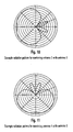
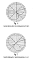
- N 4 fixed beam antennas
- the radiation patterns of these fixed beam antennas in this example are shown in fig. 6, fig. 7 , fig. 8 and fig. 9 .
- Table 1 summarizes these combinations and presents for each combination, the members of the set Aj and the numerical value of C j so that equation 1 can be calculated. For each combination, the relevant figure, for the corresponding antenna radiation pattern is also presented.
- the presented structure and method can of course directly be applied to case where the beams are combined.
- receivers 1 which have one receiver chain and receivers 1' which have multiple receiver chains.
- M is the number of sub-carriers
- n T is the number of transmitter antennas
- ⁇ n 2 is the variance of the noise
- I m 2 is the power of the interference for beam possibility i .
- the beams for the different receivers are selected so as to maximise the average SINR (or SNR) ratio, and to minimise the correlation factor of the different channel responses between the transmitters and the receivers.
- an alternative selection rule would be that the chosen beam q has a SINR value which is within the top T SINR values possible and that the correlation factor is within the lowest U values possible.
- T and U are implementation specific.
- each receiver has N beam possibilities (or 2 N -1 possibilities if the beams for each receiver are combined)
- the total number of beam possibilities for the multiple receiver case is n R N (or n R (2 N - 1) possibilities if the beam for each receiver can be combined). These possibilities are indexed using the variable q .
- SINR q 1 Mn R .
- ⁇ m 1 M
- ⁇ r 1 n R h m , r ⁇ 1 q 2 ⁇ n 2 + I n 2 q
- SINR q 1 Mn R .
- n T is the number of transmitter antennas
- n R is the number of receiver antennas
- ⁇ n 2 is the variance of the noise
- I m 2 is the power of the interference for beam possibility q .
- H Hermitian transpose (or complex transpose conjugate) operator.
- the matrix H ( q ) is the channel matrix (with n R rows and n T columns) containing all of the channel responses between the transmitters and the receivers for beam possibility q .
- vec( H ( q )).vec H ( H ( q )) product in equation (9) is therefore a matrix with n T n R row and n T n R columns.
- the expectation values can be formed by averaging over multiple channel estimates for the beam possibility q obtained from multiple channel estimation slots for the beam possibility q .
- the correlation matrix R ( q ) (from equation 9) contains in it's off diagonal elements the correlation of all of the channel responses with respect to each other whereas the diagonal elements of R ( q ) contains the power of the different channel responses.
Landscapes
- Engineering & Computer Science (AREA)
- Computer Networks & Wireless Communication (AREA)
- Signal Processing (AREA)
- Radio Transmission System (AREA)
- Mobile Radio Communication Systems (AREA)
Description
- The present invention relates to a device for transmitting and/or receiving signals in a wireless communication system and a method for controlling a selection of antennas in a wireless communication system.
- The term "selection of antennas" as used in the present specification comprises the selection of antennas or antenna elements from a number of antennas or antenna elements in order to form or create a suitable antenna beam from the selected antennas or antenna elements, as well as the combination of some or all of the number of available antenna elements or antennas in order to form a suitable combined antenna beam.
- Generally, antenna beams can be created in a transmitting and/or in a receiving device. They are typically created by selecting a suitable one out of a number of fixed beam antenna elements or antennas or by a combination of selected ones of the fixed beam antenna elements or antennas. A fixed beam antenna or antenna element can hereby be any kind of antenna or antenna element which has at least a temporarily fixed beam, e.g. a beam which is always pointing in the same (main) direction or a beam which is variable in relation to its direction but can be fix for a certain period of time.
- Typically, the beam forming of antennas is used in radio communication systems in order to increase the signal-to-noise ratio (SNR). In case that interference between simultaneously or in parallel transmitted data streams or signals is present, antenna beam forming is used to increase the signal-to-interference-plus-noise ratio (SINR) by increasing the wanted signal power and/or decreasing the power of unwanted interference. In case of receiving devices which have more than one receiving chain, e.g. for a diversity reception, the reception of Multiple Input, Multiple Output (MIMO) transmissions and the like, it is important that the signals received by the different receiving chains are as uncorrelated as possible in order to optimize the performance.
- Document
EP1553717 discloses a method for exchanging channel information" between a transmitter and a receiver each including antennas. A request frame including a first preamble, second preamble, and channel information feedback request is transmitted to the receiver, wherein the first preamble is transmitted from one of the antennas of the transmitter, the second preamble is transmitted from each of the antennas, and the channel information feedback request is transmitted from the one of the antennas. The request frame is received at the receiver, and the channel information feedback request is detected by a decoding based on the first preamble. Channel information is estimated using the second preamble, and a notification frame including the estimated information is constructed and transmitted to the transmitter. The channel state can be estimated for possible combinations of antennas. - Document
WO9810531 - Document "Transmit diversity by antenna selection in CDMA downlink", 1998, by Hottinen et al. discloses transmit diversity concepts in DS/CDMA wireless networks with multiple transmit antennas. It is also disclosed a selective transmit diversity for CDMA systems, wherein bits are transmitted only from the best antenna.
- Document
W00072464 - The object of the present invention is therefore to provide a device for transmitting and/or receiving signals in a wireless communication system and a method for controlling a selection of antennas in a wireless communication system, which enable to control a number of antennas in a way to achieve the best performance.
- The above object is achieved by a device and a method for transmitting and/or receiving signals in a wireless communication system according to
claims - The term "antenna" is hereby intended to comprise all kinds of antennas, antenna elements, antenna devices, antenna array elements and the like. Each of the antennas has a fundamental antenna beam radiation pattern. The term "fundamental antenna beam radiation pattern" is hereby intended to comprise fixed (or at least temporarily fixed) beam directions, such as directed beam positions, narrow beam positions and the like, as well as omni-directional antenna beams. The number of antennas can comprise a combination of antennas with fixed (or temporarily fixed) or narrow beam antenna beams and omni-directional antenna beams, or comprises only antennas with a narrow beam direction or antennas with an omni-directional beam shape. Further, in case that some or all of the number of antennas have a narrow or directed beam, the directions of the different beams can be the same or can be different for each of the antennas. The term "fundamental" is intended to comprise any kind of main, essential, predominant and the like radiation direction which characterizes the radiation direction of the respective fixed or temporarily fixed antenna beam.
- Advantageously, the communication system is a system in which signals are transmitted and received in preambles and data sections, a preamble comprising a respective preamble slot with channel estimation information for at least each of said fundamental antenna beam radiation patterns, wherein said antenna beam selection controller is adapted to control a selection of said antennas so that each antenna receives the respective preamble slot with the channel estimation information for the respective fundamental antenna beam and wherein said channel estimator is adapted to obtain a channel estimate for at least each of said fundamental antenna beam radiation patterns from the respective received channel estimation information.
- Further advantageously, the antenna beam selection controller is adapted to control the selection of antennas by calculating a signal-to-noise value on the basis of the obtained channel estimates. This is particularly suitable in case that the device of the present invention comprises a single receiver chain. It is to be noted that the signal-to-noise value can e.g. be a signal-to-noise ratio value or a signal-to-interference-plus-noise ratio or estimates thereof. Advantageously, the antenna beam selection controller is adapted to control a selection of antennas on the basis of one of the highest of said calculated signal-to-noise values.
- Alternatively, the antenna beam selection controller is adapted to control a selection of antennas on the basis of a signal-to-noise value and a correlation factor. This signal-to-noise value can also be a SNR or SINR value or an estimate thereof. This alternative is particularly suitable if the device of the present invention comprises two or more receiver chains. In this case, the antenna beam selection controller is advantageously adapted to control a selection of antennas on the basis of one of the highest of said calculated signal-to-noise values and one of the lowest of said correlation factors. Further advantageously, the antenna beam selection controller is adapted to calculate the correlation factors on the basis of a correlation matrix in this case. Hereby, the antenna beam selection controller is advantageously adapted to calculate said correlation factor on the basis of the sum of the power of the non-diagonal elements of the correlation matrix divided by the sum of the power of the diagonal elements of the correlation matrix.
- The method according to the present invention can be further advantageously implemented by the method steps of one of the dependent method claims.
- Further, the present invention is directed to a computer program adapted to be loaded into an internal memory of a communication device, wherein said computer program is adapted to perform the method of one of the method claims of the present invention and run on said communication device.
- The present invention is further explained in more detail in the following description of preferred embodiments in relation to the enclosed drawings, in which
-
Fig. 1 shows a schematic block diagram of a transmitting and/or receiving device of the present invention, -
Fig. 2 shows a schematic example of a preamble section and a data section according to the present invention, -
Fig. 3 shows a schematic block diagram of an alternative embodiment of the transmitting and/or receiving device of the present invention, -
Fig. 4 shows a schematic block diagram of a first possible implementation of some of the elements of the device shown infig. 1 , -
Fig. 5 shows a schematic block diagram of a second possible implementation of some of the elements of the device shown infig. 1 , -
Fig. 6 shows a first example of a radiation pattern, -
Fig. 7 shows a second example of a radiation pattern, -
Fig. 8 shows a third example of a radiation pattern, -
Fig. 9 shows a fourth example of a radiation pattern, -
Fig. 10 shows a fifth example of a radiation pattern, -
Fig. 11 shows a sixth example of a radiation pattern, -
Fig. 12 shows a seventh example of a radiation pattern, -
Fig. 13 shows an eighth example of a radiation pattern, -
Fig. 14 shows a ninth example of a radiation pattern, -
Fig. 15 shows a tenth example of a radiation pattern, -
Fig. 16 shows an eleventh example of a radiation pattern, -
Fig. 17 shows a twelfth example of a radiation pattern, -
Fig. 18 shows a thirteenth example of a radiation pattern, -
Fig. 19 shows a fourteenth example of a radiation pattern, -
Fig. 20 shows a fifteenth example of a radiation pattern. -
Fig. 1 schematically shows an example of adevice 1 for transmitting and/or receiving signals in a wireless communication system, e.g. an orthogonal frequency division multiplexing (OFDM) system, according to the present invention. Infig. 1 , only elements of thedevice 1 according to the present invention which are necessary to explain and understand the present invention are shown. However, it is to be understood that a practical implementation of the transmitting and/or receiving device would comprise additional elements necessary for the practical operation. - The
device 1 is adapted to receive signals in the wireless communication system via a number ofantennas 2, whereby each of theantennas 2 has a fundamental antenna beam radiation pattern. Hereby, the wireless communication system can be any kind of wireless communication system enabling the transmission and/or reception of signals over short range, middle range or long range distances, using any kind of present or future communication system, including but not limited to a GSM system, a UMTS system, WLAN system, short range, mid range, long range systems, any kind of modulation and so forth. - The
device 1 comprises a number ofantennas 2, whereby eachantenna 2 can be implemented as an antenna, antenna element, an antenna device, an antenna unit, part of an antenna array or the like. Each of theantennas 2 has a fundamental antenna beam radiation pattern. E.g., in case that each of theantennas 2 has a fixed omni-directional transmission and/or reception characteristic, this omni-directional characteristic is the fundamental antenna beam radiation pattern. As a further example, in case that eachantenna 2 has a narrow beam or directional antenna characteristic, this direction beam characteristic would be the fundamental antenna beam radiation pattern. - The
device 1 comprises an antennabeam selection controller 3 adapted to control a selection of saidantennas 2 for the transmission and/or reception of signals on the basis of channel estimates obtained at least for each of said fundamental antenna beam radiation patterns. The antennabeam selection controller 3 hereby controls an antenna beam selector 5 which selects one or more of saidantennas 2 or any kind of combination of two or more of saidantennas 2 on the basis of respective control signals received from the antennabeam selection controller 3. Hereby, a combined transmission and/or reception beam of the selectedantennas 2 or a combination of the selectedantennas 2 is formed in order to achieve the best transmission and/or reception performance. The selection of theantennas 2 in the antennabeam selection controller 3 is hereby controlled on the basis of channel estimates obtained from achannel estimator 4. - As stated further above, the
device 1 comprises all elements necessary for the reception and/or transmission of signals in a wireless communication system, whereby some of the elements are shown infig. 1 and some other elements are omitted for the sake of clarity. E.g., thedevice 1 comprises adownconversion unit 6 for downconverting signals received via the number ofantennas 2 through the antenna beam selector 5. The downconverted signals from thedownconversion unit 6 are forwarded to aFourier transformation unit 7 which transforms the time domain signals into frequency domain signals, which are then equalized by anequalizer 8 and, after equalization, further processed in a processing unit 9 e.g. by de-interleaving the signals and so forth. The processed signals are then further processed in thedevice 1 as necessary. In theequalizer 8, channel estimation values obtained and calculated by thechannel estimator 4 from the time domain signals output by aFourier transformation unit 7 are used. The detailed functionality of achannel estimator 4 is known in the art and is omitted here for the sake of clarity. In brief, thechannel estimator 4 provides a channel estimate value for each transmission channel of the communication system. According to the present invention, thechannel estimator 4 obtains a channel estimate for at least each of the fundamental antenna beam radiation patterns of theantennas 2 on the basis of correspondingly received channel estimation information. Hereby, in the wireless communication system of the present invention, a separate channel estimation is transmitted for at least each of the fundamental antenna beam radiation patterns of theantennas 2. E.g., if the number ofantennas 2 is N (N being a natural number), at least N different channel estimation information values are transmitted in the wireless communication system and received by theantennas 2. Hereby, the reception of the channel estimation information values by therespective antennas 2 is controlled by the antennabeam selection controller 3 in a way that eachantenna 2 receives its respectively allocated channel estimation information value. E.g., in case that the wireless communication system of the present invention transmits and receives signals and preambles and data sections, as shown schematically infig. 5 , the preamble section may comprise N different channel estimation slots, whereby channel estimation information values for each of theantennas 2 is transmitted in each of the channel estimation slots N. In other words, for each of the channel estimation slots N, the antennabeam selection controller 3 switches to adifferent antenna 2 and is therefore adapted to obtain a channel estimate for each of the fundamental antenna beam radiation patterns for each preamble. This principle can also be adapted to combinations ofantennas 2 and therefore to combinations of the fundamental antenna beam radiation patterns. E.g., the maximum number of combinations of fundamental antenna beam radiation patterns ofantennas 2 is 2N-1, in which case 2N-1 channel estimation slots could be transmitted in the preamble section. However, according to the present invention it is more advantageous to only transmit N channel estimation slots, since the present invention enables the calculation of channel estimates for the 2N-1 combinations on the basis of the N channel estimation information values. - It is to be noted that the
device 1 shown infig. 1 only shows a single receiver chain. However, the concept of the present invention can also be applied to multiple receiver chains, such as two or more receiver chains. An example is shown infig. 3 , in which an alternative embodiment of a device 1' for transmitting and/or receiving signals in a wireless communication system according to the present invention is shown, which has two receiver chains. The first receiver chain with a number ofantennas 2, an antenna beam selector 5, adownconversion unit 6, aFourier transformation unit 7 corresponds to corresponding elements of thedevice 1 offig. 1 . Further, a second receiver chain with a number of antennas 2', anantenna beam selector 15, adownconversion unit 16 and a Fourier transformation unit 17 is shown. All explanations and functionalities explained above in relation to theantennas 2 also apply to the antennas 2'. The same is true for theantenna beam selector 15 in view of the antenna beam selector 5, thedownconversion unit 16 in relation to thedownconversion unit 6 and the Fourier transformation unit 17 in relation to theFourier transformation unit 7. The device 1' further comprises anequalizer 18 which is adapted to equalize the signals from both theFourier transformation units 7 and 17 in the same way as theequalizer 8. The equalized signals are then further processed in the twoparallel processing units channel estimator 19 obtains and calculates channel estimates from the signals output by theFourier transformation units 7 and 17 and provides channel estimation values to theequalizer 18 as well as to an antennabeam selection controller 20. The antennabeam selection controller 20 works in the same way as explained above in relation to the antennabeam selection controller 3, but controls the antenna beams of the number ofantennas 2 as well as the number of antennas 2'. The number antennas 2' is hereby selected and controlled via theantenna beam selector 15. - A non-limiting example for an implementation of an antenna beam selector 5 and/or 15 is shown in
fig. 4. Fig. 4 shows a beam forming structure which uses a combination of fixed (or temporarily fixed) antenna branches, one antenna branch for eachantenna 2. Theantennas 2 may have omni-directional characteristics or any other kind of directional characteristics depending on the wanted implementation. Each branch of eachantennas 2 has again amplifier 10 and anRF phase shifter 11. Thegain amplifiers 10 and thephase shifters 11 are connected to and controlled by a gain andphase computation unit 13 which is an example for an implementation of the antennabeam selection controller antenna 2, the angle of the received signal for which the combined N branches has the highest gain is changed and therefore the received beam (or transmitted beam) can be steered. By changing the amplifier gain for each antenna branch, the weight of the individual branches for the succeedingRF combiner 12, in which the signals from the antenna branches are combined, is changed and therefore the exact beam receiver sensitivity (beam transmitter sensitivity) against angle can be changed. If only a certain set of beams need to be used, the exact gain and phases required for the different branches can be stored in a lookup table or computed on-line in the gain andphase computation unit 13 and these beams can then be selected correspondingly. The combined signal output from theRF combiner 12 is then further processed in the downconversion unit 6 (and/or the downconversion unit 16). It is to be understood thatfig. 2 shows the case for a receiving device. For a transmitting device, a similar arrangement is used but the signals travel from right to left and not from left to right and theRF combiner 12 is replaced by a power splitter. An alternative implementation of the amplification gain control and phase shifting for each antenna branch instead of the RF part of the transmitting and/or receiving device as shown infig. 4 is the implementation in the base band structure of the transmitting and/or receiving device. -
Fig. 5 shows a further alternative implementation example for an antenna beam selector 5. In the example offig. 5 , the antenna beam selector 5 is implemented as an N-way switch 14 adapted to selectively switch to and choose one of the number ofN antennas 2. Each of theantennas 2 has a different radiation pattern so that by choosing the best suited radiation pattern and thecorresponding antenna 2 the best performance can be achieved. The N-way switch 14 is controlled by the antennabeam selection controller 3 in the usual manner. In this implementation example, a combination of two ormore antennas 2 is not possible. The shown implementation offig. 5 can be equally applied to a transmitting and a receivingdevice 1. - It is to be understood that the implementation examples of
figs. 4 and 5 are only examples and that alternative and/or additional implementations are possible, such as an implementation in which not onlysingle antennas 2 can be selected by the antenna beam selector 5, but also combinations of two or more of theantennas 2 can be combined in order to obtain the best beam for the given transmission and reception scenario. - In the following, the functionalities of the
channel estimator beam selection controller - Hereby, in order to explain the implementation, and implementation structure and method to select and combine the antenna beams for the
communication device 1,1' which is in receiving mode is explained. However, the selected beams can be used by thecommunication device 1, 1' at a later time period during the transmitting mode. Therefore, specifically for communication systems using time division duplex and which the channels are not significantly changing between uplink and downlink time slots (reciprocal channel case), the method and implementation described in the following for the beam selection/combination can be readily applied for a transmitter device as well as for a receiver device. - For the following explanation is assumed that the beams are formed using the fixed beam switching as shown and explained in relation to
fig. 5 and the fixed beam combining as shown and explained in relation tofigs. 1 and3 , but it is to be understood that the concept of the present invention is also applicable to the beam forming as explained in relation tofig. 4 , when a finite number of beams are used using the described gain and phase computation (or lookup table) computation in theblock 13 or in a similar block if the beams are formed in base band processing. - In order to explain the idea underlying the present invention, the following explanation is split into two parts, namely the channel estimation and the beam selection.
- As explained above in relation to
fig. 2 , according to the present invention a channel estimation information value is available for each of theantennas 2 or 2', e.g. by providing a channel estimation slot for each of theantennas 2 in a preamble section. - The present invention proposes that for each of these channel estimation slots, the receiver (or the communication unit in receiving mode) switches to a different fundamental beam position and thereby can obtain a channel estimate for each of the fundamental beam positions for each preamble.
- For a typical mobile communications system operating in a multi-path channel, each channel estimate will have many components spaced in time. To simplify the mathematical explanation here, it is assumed that the channel estimate for each beam is a single complex value, which corresponds to the case of a typical channel estimate for an orthogonal multiplexing division system (OFDM) system or a system for which there is a only a single multi-path component. All the concepts presented here, can of course be used for other systems.
- Furthermore, since the
receiver 1,1' may have n R receiver chains which could each receive signals from n T transmitters on M sub-carriers, a general representation for channel estimation is given by hm, rt (i) where m denotes the sub-carrier number (m = 1,...,M) , r denotes the receiver number (r= 1,..., n R), t denotes the transmitter number (t = 1,..., n T) and i denotes the beam number (i =1 ,..., N) . For simplicity and without loss of generality, it is assumed in this section here that thedevice 1, 1' has one receiver chain and is receiving a signal from one transmitter. The following refers to the channel estimates for one carrier and therefore the subscript m is dropped for the sake of clarity. The channel estimates for the fundamental beam (fundamental antenna beam radiation pattern) will therefore be denoted as h (i) where i=1 ,..., N. - If the
receiver 1,1' is capable of combining the fundamental beams it is proposed that the channel estimations for the combined beams are obtained from the summation of the corresponding fundamental beams. Denoted mathematically, channel estimation b ( j) for the fundamental beams and their combinations, where j=1 ,..., 2 N - 1 is given by,
Where Aj is the set of fundamental beams which are summed to form the beam number j and Cj is the number of beams which are contained in the set Aj. - To explain this more clearly, as an example a system with N = 4 fixed beam antennas is used. It is to be understood, however, that the present invention is not limited to this number. The radiation patterns of these fixed beam antennas in this example are shown in
fig. 6, fig. 7 ,fig. 8 and fig. 9 . These beams can be combined in 15 different ways (2 N -1= 15). Table 1 summarizes these combinations and presents for each combination, the members of the set Aj and the numerical value of Cj so thatequation 1 can be calculated. For each combination, the relevant figure, for the corresponding antenna radiation pattern is also presented.Table 1- Example fixed beam antenna combinations (N=4) Combination number j Set Aj Cj Example Radiation patterns j=1 A 1 ={1} C1= 1 Figure 6 j=2 A 2 = {2} C2 = 1 Figure 7 j=3 A 3 = {3} C3 = 1 Figure 8 j=4 A 4 = {4} C4 = 1 Figure 9 j=5 A 5 = {2,3} C5 = 2 Figure 10 j=6 A 6 = {1,2} C6 = 2 Figure 11 j=7 A 7 = {11,4} C7 =2 Figure 12 j=8 A 8 = {3,4} C8 =2 Figure 13 j=9 A 9 = {2,4} C9 =2 Figure 14 j=10 A 10= {1,3} C10=2 Figure 15 j=11 A 11= {2,3,4} C11=3 Figure 16 j=12 A 12 = {1,3,4} C12=3 Figure 17 j=13 A 13 = {1,2,3} C13=3 Figure 18 j=14 A 14 = {1,2,4} C14=3 Figure 19 j=15 A 15 = {1,2,3,4} C15 = 4 Figure 20 - For this example, by referring to
equation 1 and Table 1, for combination 14 (which has a radiation pattern as shown infig. 19 ) the channel estimation b (14) is computed as follows,
- If the beams can be combined, the decision made in the antenna
beam relation controller - The following makes a distinction between
receivers 1 which have one receiver chain and receivers 1' which have multiple receiver chains. - For
receivers 1, which have only one receiver, it is proposed that the beam which has a channel estimate corresponding to the highest signal to noise ratio (SNR) or the highest average signal to interference plus noise ratio, (SINR) should be selected. In the next sub-section possible ways to estimate the SINR from the channel estimates are explained. - Some possible implementations or methods to calculate the average SINR for each beam possibility i for different system configurations are as follows,
- (a) A single carrier system with one receiver and one transmitter

- (b) System with one receiver, one transmitter and M sub-carriers (≡ typical OFDM system)

- (c) System with one receiver, receiving signals from n T transmitters with M sub-carriers
(≡ typical OFDM system with transmit diversity)
- Where M is the number of sub-carriers, nT is the number of transmitter antennas,


- Other methods to estimate the SINR are also possible.
- For receivers, e.g. receiver 1', which have multiple receiver chains, it is proposed that the beams for the different receivers are selected so as to maximise the average SINR (or SNR) ratio, and to minimise the correlation factor of the different channel responses between the transmitters and the receivers.
- Since it may not always be possible to find a beam position which maximises the SINR and at the same time minimises the correlation factor, an alternative selection rule would be that the chosen beam q has a SINR value which is within the top T SINR values possible and that the correlation factor is within the lowest U values possible. T and U are implementation specific.
- In the next section it is explained how the average SINR can be calculated for multiple receiver chains and proposes a new method to calculate the correlation factor.
- Since each receiver has N beam possibilities (or 2N -1 possibilities if the beams for each receiver are combined), the total number of beam possibilities for the multiple receiver case is nR N (or nR (2N -1) possibilities if the beam for each receiver can be combined). These possibilities are indexed using the variable q.
- Some possible methods to calculate the average SINR for each of these beam possibilities q , for different system configurations is as follows,
- (a) A single carrier system with n R receivers and one transmitter

- System with n R receivers, one transmitter and M sub-carriers
( ≡ typical OFDM system with receiver diversity)
- System with n R receivers, one transmitter and M sub-carriers
(≡ typical MIMO OFDM system)
- Where M is the number of sub-carriers, n T is the number of transmitter antennas, n R is the number of receiver antennas,


- Other measures for SINR would also be possible.
- To estimate the correlation factor between the received signals for each of the beam possibilities q, it is proposed to estimate first the correlation matrix R(q) for each of the these possibilities,

- Where E [.] denotes the expectation (or mean) operation, vec (.) is the vectorization operation and the superscript H is the Hermitian transpose (or complex transpose conjugate) operator. The matrix H(q) is the channel matrix (with n R rows and n T columns) containing all of the channel responses between the transmitters and the receivers for beam possibility q. H(q) is given by,

- The vec (.) operation stacks the columns of H (q) to form a vector with n T n R rows,

- The vec(H(q)).vecH (H(q)) product in equation (9) is therefore a matrix with n T n R row and n T n R columns.
- To obtain the expectation value needed for equation (9), there are several possibilities. If we are using a system with M sub-carriers (a typical OFDM system), one possibility is to form the expectation values by averaging over the channel matrix for each sub-carrier.

where
- Alternatively, if the system is only using one carrier, the expectation values can be formed by averaging over multiple channel estimates for the beam possibility q obtained from multiple channel estimation slots for the beam possibility q.
- The correlation matrix R(q) (from equation 9) contains in it's off diagonal elements the correlation of all of the channel responses with respect to each other whereas the diagonal elements of R(q) contains the power of the different channel responses.
- We therefore propose to calculate our correlation factor (which indicates the level of correlation for the different channel responses) for each beam possibility q as follows,
-

Where rij (q) is the element located at the ith row and jth column of matrix R(q)
Claims (19)
- Device (1) for transmitting and/or receiving signals in a wireless communication system, comprising- a number of antennas (2), each of the antennas (2) having a fundamental antenna beam radiation pattern,- an antenna beam selection controller (3; 10) adapted to control a selection or combination of said antennas (2) for the transmission and/or reception of signals on the basis of channel estimates obtained at least for each of the fundamental antenna beam radiation patterns and at least for some combinations of the fundamental antenna beam radiation patterns, and- a channel estimator (4; 19) adapted to obtain a channel estimate for a combination of fundamental antenna beam radiation patterns by the sum of the channel estimates of the corresponding fundamental antenna beam radiation patterns divided by the number of corresponding fundamental beam positions.
- Device (1) according to claim 1,
comprising a channel estimator (4; 19) adapted to obtain said channel estimates on the basis of channel estimation information received for at least each of the fundamental antenna beam radiation patterns. - Device (1) according to claim 1 or 2,
wherein signals in said communication system are transmitted and received in preambles and data sections, a preamble comprising a respective preamble slot with channel estimation information for at least each of said fundamental antenna beam radiation patterns, wherein said antenna beam selection controller (3; 20) is adapted to control the selection of said antennas (2) so that each antenna (2) receives the respective preamble slot with the channel estimation information for the respective fundamental antenna beam and wherein said channel estimator (4:19) is adapted to obtain a channel estimate for at least each of said fundamental antenna beam radiation patterns from the respective received channel estimation information. - Device (1), according to one of the claims 1 to 3,
comprising a single receiver chain, wherein said antenna beam selection controller (4) is adapted to control the selection of antennas by calculating a signal-to-noise value on the basis of the obtained channel estimates. - Device (1) according to claim 4,
wherein said antenna beam selection controller is adapted to control the selection of antennas on the basis of one of the highest of said calculated signal-to-noise values. - Device (1) according to one of the claims 1 to 3,
comprising two or more receiver chains, wherein said antenna beam selection controller (20) is adapted to control the selection of antennas on the basis of a signal-to-noise value and a correlation factor. - Device (1) according to claim 6,
wherein said antenna beam selection controller (20) is adapted to control the selection of antennas on the basis of one of the highest of said calculated signal-to noise values and one of the lowest of said correlation factors. - Device (1) according to claim 6 or 7,
wherein said antenna beam selection controller (20) is adapted to calculate said correlation factors on the basis of a correlation matrix. - Device (1) according to claim 8,
wherein said antenna beam selection controller (20) is adapted to calculate said correlation factor on the basis of the sum of the power of the non diagonal elements of the correlation matrix divided by the sum of the power of the diagonal elements of the correlation matrix. - Method for controlling a selection or combination of antennas in a wireless communication system, wherein a selection or combination of antennas for the transmission and/or reception of signals from a number of antennas, each of the number of antennas having a fundamental antenna beam radiation pattern, is controlled on the basis of channel estimates obtained at least for each of the fundamental antenna beam radiation patterns and at least for some combinations of the fundamental antenna beam radiation patterns, and wherein a channel estimate is obtained for a combination of fundamental antenna beam radiation patterns by the sum of the corresponding channel estimates of the fundamental antenna beam radiation patterns divided by the number of corresponding fundamental beam positions.
- Method according to claim 10,
wherein said channel estimates are obtained on the basis of channel estimation information received for at least each of the fundamental antenna beam radiation patterns. - Method according to claim 10 or 11,
wherein signals in said communication system are transmitted and received in preambles and data sections, a preamble comprising a respective preamble slot with channel estimation information for at least each of said fundamental antenna beam radiation patterns, wherein the selection of said antennas is controlled so that a each antenna receives the respective preamble slot with the channel estimation information for the respective fundamental antenna beam and wherein a channel estimate is obtained for at least each of said fundamental antenna beam radiation patterns from the respective received channel estimation information. - Method according to one of the claims 10 to 12,
wherein said selection of antennas is controlled by calculating a signal-to-noise value on the basis of the obtained channel estimates. - Method according to claim 13,
wherein said selection of antennas is controlled on the basis of one of the highest of said calculated signal-to-noise values. - Method according to one of the claims 10 to 12,
therein said the selection of antennas is controlled on the basis of a signal-to-noise value and a correlation factor. - Method according to claim 15,
wherein said selection of antennas is controlled on the basis of one of the highest of said calculated signal-to-noise values and one of the lowest of said correlation factors. - Method according to claim 15 or 16,
wherein said correlation factors are calculated on the basis of a correlation matrix. - Method according to claim 17,
wherein said correlation factor is calculated on the basis of the sum of the power of the non diagonal elements of the correlation matrix divided by the sum of the power of the diagonal elements of the correlation matrix. - Computer program adapted to be loaded into an internal memory of a
communication device, wherein said computer program comprising program means adapted to perform the steps of the method of one of the claims 10 to 18 when run on said communication device
Priority Applications (4)
| Application Number | Priority Date | Filing Date | Title |
|---|---|---|---|
| EP06017364A EP1892852B1 (en) | 2006-08-21 | 2006-08-21 | Device and method for controlling a selection of antennas in a wireless communication system |
| DE602006014398T DE602006014398D1 (en) | 2006-08-21 | 2006-08-21 | Apparatus and method for selecting antennas in a radio communication system |
| US11/842,536 US7894542B2 (en) | 2006-08-21 | 2007-08-21 | Device and method for controlling a selection of antennas in a wireless communication system |
| JP2007214952A JP2008061238A (en) | 2006-08-21 | 2007-08-21 | Device and method for controlling selection of antennas in wireless communication system |
Applications Claiming Priority (1)
| Application Number | Priority Date | Filing Date | Title |
|---|---|---|---|
| EP06017364A EP1892852B1 (en) | 2006-08-21 | 2006-08-21 | Device and method for controlling a selection of antennas in a wireless communication system |
Publications (2)
| Publication Number | Publication Date |
|---|---|
| EP1892852A1 EP1892852A1 (en) | 2008-02-27 |
| EP1892852B1 true EP1892852B1 (en) | 2010-05-19 |
Family
ID=37613896
Family Applications (1)
| Application Number | Title | Priority Date | Filing Date |
|---|---|---|---|
| EP06017364A Expired - Fee Related EP1892852B1 (en) | 2006-08-21 | 2006-08-21 | Device and method for controlling a selection of antennas in a wireless communication system |
Country Status (4)
| Country | Link |
|---|---|
| US (1) | US7894542B2 (en) |
| EP (1) | EP1892852B1 (en) |
| JP (1) | JP2008061238A (en) |
| DE (1) | DE602006014398D1 (en) |
Families Citing this family (7)
| Publication number | Priority date | Publication date | Assignee | Title |
|---|---|---|---|---|
| US7982671B2 (en) * | 2008-04-17 | 2011-07-19 | Broadcom Corporation | Method and system for using a wireless local area network (WLAN) phase shifter for smart antenna beam steering |
| US20110065391A1 (en) * | 2008-05-27 | 2011-03-17 | Akihiko Shiotsuki | Wireless communication apparatus for changing directional pattern of variable directivity antenna according to variations in radio wave propagation enviroment |
| EP2219299B1 (en) | 2009-02-17 | 2012-11-14 | Sony Corporation | Beam selection method |
| EP4235608A3 (en) | 2013-08-08 | 2023-10-11 | Angel Playing Cards Co., Ltd. | A method for administrating a package of shuffled playing cards |
| US10673652B2 (en) * | 2017-03-02 | 2020-06-02 | Futurewei Technologies, Inc. | System and method for providing explicit feedback in the uplink |
| CN107017933A (en) * | 2017-05-09 | 2017-08-04 | 电子科技大学 | A kind of MIMO data transmission methods and device for merging smart antenna |
| US10715233B2 (en) * | 2017-08-31 | 2020-07-14 | Qualcomm Incorporated | Sounding reference signal (SRS) transmit antenna selection |
Family Cites Families (11)
| Publication number | Priority date | Publication date | Assignee | Title |
|---|---|---|---|---|
| WO1998010531A1 (en) | 1996-09-04 | 1998-03-12 | Ascom Tech Ag | Preamble for the assessment of channel impulse response in a antenna diversity system |
| JP3108641B2 (en) * | 1996-11-21 | 2000-11-13 | 株式会社ワイ・アール・ピー移動通信基盤技術研究所 | Receiver |
| JP2000059279A (en) * | 1998-08-11 | 2000-02-25 | Nippon Telegr & Teleph Corp <Ntt> | Method and device for digital highs-speed radio communication |
| WO2000072464A1 (en) | 1999-05-19 | 2000-11-30 | Nokia Networks Oy | Transmit diversity method and system |
| DE60021772T2 (en) * | 2000-04-07 | 2006-04-20 | Nokia Corp. | METHOD AND DEVICE FOR TRANSMITTING WITH SEVERAL ANTENNAS |
| JP3999000B2 (en) * | 2002-03-07 | 2007-10-31 | 三菱電機株式会社 | Array antenna device |
| JP4184854B2 (en) * | 2003-04-07 | 2008-11-19 | 株式会社エヌ・ティ・ティ・ドコモ | Radio wave transmission / reception device and radio wave transmission / reception method |
| JP3947166B2 (en) | 2004-01-09 | 2007-07-18 | 株式会社東芝 | COMMUNICATION SYSTEM, COMMUNICATION DEVICE, AND COMMUNICATION METHOD |
| JP3906209B2 (en) * | 2004-01-26 | 2007-04-18 | 株式会社東芝 | Radio receiving apparatus and radio receiving method |
| US8483200B2 (en) * | 2005-04-07 | 2013-07-09 | Interdigital Technology Corporation | Method and apparatus for antenna mapping selection in MIMO-OFDM wireless networks |
| EP1843485B1 (en) | 2006-03-30 | 2016-06-08 | Sony Deutschland Gmbh | Multiple-input multiple-output (MIMO) spatial multiplexing system with dynamic antenna beam combination selection capability |
-
2006
- 2006-08-21 EP EP06017364A patent/EP1892852B1/en not_active Expired - Fee Related
- 2006-08-21 DE DE602006014398T patent/DE602006014398D1/en active Active
-
2007
- 2007-08-21 JP JP2007214952A patent/JP2008061238A/en active Pending
- 2007-08-21 US US11/842,536 patent/US7894542B2/en not_active Expired - Fee Related
Also Published As
| Publication number | Publication date |
|---|---|
| US20080056406A1 (en) | 2008-03-06 |
| US7894542B2 (en) | 2011-02-22 |
| EP1892852A1 (en) | 2008-02-27 |
| JP2008061238A (en) | 2008-03-13 |
| DE602006014398D1 (en) | 2010-07-01 |
Similar Documents
| Publication | Publication Date | Title |
|---|---|---|
| KR100958501B1 (en) | Wireless communication system | |
| JP5230766B2 (en) | Arrival direction estimation apparatus and arrival direction estimation method | |
| JP5230779B2 (en) | Wireless communication apparatus and wireless communication method | |
| KR101513889B1 (en) | Apparatus and method for switched beam-forming using multi-beam combining | |
| EP1545024B1 (en) | Adaptive antenna radio communication device | |
| EP3355483B1 (en) | Method for determining beamforming parameters in a wireless communication system and to a wireless communication system | |
| EP1985125B1 (en) | Method and apparatus for performing spatial-division multiple access | |
| JP4594881B2 (en) | Multi-input multi-output communication device | |
| US8102830B2 (en) | MIMO radio communication apparatus and method | |
| EP1892852B1 (en) | Device and method for controlling a selection of antennas in a wireless communication system | |
| US20120063540A1 (en) | Ofdm signal transmission method and apparatus | |
| US8750401B2 (en) | Sequential transmission multi-beamforming method with low complexity using Hadamard matrix | |
| KR101413937B1 (en) | Method and appratus selecting transmit antenna and estimating uplink multiple-input multiple-output channels in time-division multiplexing wireless communication systems | |
| EP3791484A1 (en) | Methods and devices for polarization optimization of mimo wireless transmission | |
| JP4820848B2 (en) | Adaptive antenna wireless communication apparatus and adaptive antenna wireless communication method | |
| JP5278279B2 (en) | Wireless communication system | |
| EP2036217B1 (en) | Method and apparatus for performing stream weighting in an sdma communication system | |
| KR100903926B1 (en) | Wireless communication system | |
| KR20180010047A (en) | Apparatus and method receiving signal using single RF chain |
Legal Events
| Date | Code | Title | Description |
|---|---|---|---|
| PUAI | Public reference made under article 153(3) epc to a published international application that has entered the european phase |
Free format text: ORIGINAL CODE: 0009012 |
|
| AK | Designated contracting states |
Kind code of ref document: A1 Designated state(s): AT BE BG CH CY CZ DE DK EE ES FI FR GB GR HU IE IS IT LI LT LU LV MC NL PL PT RO SE SI SK TR |
|
| AX | Request for extension of the european patent |
Extension state: AL BA HR MK YU |
|
| 17P | Request for examination filed |
Effective date: 20080701 |
|
| 17Q | First examination report despatched |
Effective date: 20080731 |
|
| AKX | Designation fees paid |
Designated state(s): DE FR GB |
|
| GRAP | Despatch of communication of intention to grant a patent |
Free format text: ORIGINAL CODE: EPIDOSNIGR1 |
|
| RIN1 | Information on inventor provided before grant (corrected) |
Inventor name: STIRLING-GALLACHER, RICHARD |
|
| GRAS | Grant fee paid |
Free format text: ORIGINAL CODE: EPIDOSNIGR3 |
|
| GRAA | (expected) grant |
Free format text: ORIGINAL CODE: 0009210 |
|
| AK | Designated contracting states |
Kind code of ref document: B1 Designated state(s): DE FR GB |
|
| REG | Reference to a national code |
Ref country code: GB Ref legal event code: FG4D |
|
| REF | Corresponds to: |
Ref document number: 602006014398 Country of ref document: DE Date of ref document: 20100701 Kind code of ref document: P |
|
| PLBE | No opposition filed within time limit |
Free format text: ORIGINAL CODE: 0009261 |
|
| STAA | Information on the status of an ep patent application or granted ep patent |
Free format text: STATUS: NO OPPOSITION FILED WITHIN TIME LIMIT |
|
| 26N | No opposition filed |
Effective date: 20110222 |
|
| REG | Reference to a national code |
Ref country code: DE Ref legal event code: R097 Ref document number: 602006014398 Country of ref document: DE Effective date: 20110221 |
|
| PGFP | Annual fee paid to national office [announced via postgrant information from national office to epo] |
Ref country code: FR Payment date: 20110901 Year of fee payment: 6 |
|
| PGFP | Annual fee paid to national office [announced via postgrant information from national office to epo] |
Ref country code: GB Payment date: 20120821 Year of fee payment: 7 |
|
| REG | Reference to a national code |
Ref country code: FR Ref legal event code: ST Effective date: 20130430 |
|
| PG25 | Lapsed in a contracting state [announced via postgrant information from national office to epo] |
Ref country code: FR Free format text: LAPSE BECAUSE OF NON-PAYMENT OF DUE FEES Effective date: 20120831 |
|
| GBPC | Gb: european patent ceased through non-payment of renewal fee |
Effective date: 20130821 |
|
| PG25 | Lapsed in a contracting state [announced via postgrant information from national office to epo] |
Ref country code: GB Free format text: LAPSE BECAUSE OF NON-PAYMENT OF DUE FEES Effective date: 20130821 |
|
| PGFP | Annual fee paid to national office [announced via postgrant information from national office to epo] |
Ref country code: DE Payment date: 20140821 Year of fee payment: 9 |
|
| REG | Reference to a national code |
Ref country code: DE Ref legal event code: R119 Ref document number: 602006014398 Country of ref document: DE |
|
| PG25 | Lapsed in a contracting state [announced via postgrant information from national office to epo] |
Ref country code: DE Free format text: LAPSE BECAUSE OF NON-PAYMENT OF DUE FEES Effective date: 20160301 |