JP4301469B2 - Image generation system and information storage medium - Google Patents
Image generation system and information storage medium Download PDFInfo
- Publication number
- JP4301469B2 JP4301469B2 JP21916399A JP21916399A JP4301469B2 JP 4301469 B2 JP4301469 B2 JP 4301469B2 JP 21916399 A JP21916399 A JP 21916399A JP 21916399 A JP21916399 A JP 21916399A JP 4301469 B2 JP4301469 B2 JP 4301469B2
- Authority
- JP
- Japan
- Prior art keywords
- rotation
- impact
- door
- calculating
- determination information
- Prior art date
- Legal status (The legal status is an assumption and is not a legal conclusion. Google has not performed a legal analysis and makes no representation as to the accuracy of the status listed.)
- Expired - Lifetime
Links
Images


Landscapes
- Processing Or Creating Images (AREA)
Abstract
Description
【0001】
【発明の属する技術分野】
本発明は、画像生成システム及び情報記憶媒体に関する。
【0002】
【背景技術及び発明が解決しようとする課題】
従来より、仮想的な3次元空間であるオブジェクト空間内の所与の視点から見える画像を生成する画像生成システムが知られており、いわゆる仮想現実を体験できるものとして人気が高い。ガンゲームを楽しむことができる画像生成システムを例にとれば、プレーヤ(操作者)は、銃などを模して作られたガン型コントローラ(シューティングデバイス)を用いて、画面に映し出される敵キャラクタ(オブジェクト)などの標的オブジェクトをシューティングすることで、3次元ゲームを楽しむ。
【0003】
さて、このような画像生成システムでは、プレーヤの仮想現実感の向上のために、よりリアルな画像を生成することが重要な技術的課題になっている。従って、例えばドアや回転いすのように銃弾等の衝撃が加わると回転するものについてもよりリアルに表現できることが望まれる。
【0004】
例えばドアや回転いすなどが銃弾を受けた場合、銃弾を受けた位置、銃弾の方向及び大きさにより、異なる速度や大きさの回転動作を行うはずである。
【0005】
しかしながらこれまでの画像生成システムにおいては、ドアや回転いすに銃弾が当たった場合には、予め用意された回転動作の画像が生成されるだけであった。このためゲーム画面中のドアや回転いすは、どこに銃弾が当たっても、どのような方向から銃弾が当たっても同じ回転動作を行うことになり、ゲーム画像がアリティに欠けた単調なものとなっていた。
【0006】
本発明は、このような従来の課題に鑑みてなされたものであり、その目的は衝撃位置及び衝撃の大きさと方向に応じて回転動作を行うオブジェクトの画像をより少ないデータ量及び演算負荷でリアルに表現できる画像生成システム及び情報記憶媒体を提供することにある。
【0007】
【課題を解決するための手段】
本発明の画像生成システムは、所与の回転軸又は回転中心が設定されているオブジェクトに衝撃ベクトルが加わった場合に、前記オブジェクトに加わった衝撃位置及び衝撃ベクトルを演算する手段と、衝撃位置と前記オブジェクトの回転軸又は回転中心との距離及び衝撃ベクトルとに基づいて、前記オブジェクトの回転位置を決定するために必要な回転位置決定情報を演算する手段と、前記回転位置決定情報に基づいて配置されたオブジェクトを含む画像を生成する手段と、を含むことを特徴とする。
【0008】
また本発明に係る情報記憶媒体は、コンピュータにより使用可能な情報記憶媒体であって、上記手段を実現(実行)するための情報(プログラム或いはデータ等)を含むことを特徴とする。また本発明に係るプログラムは、コンピュータにより使用可能なプログラム(搬送波に具現化されるプログラムを含む)であって、上記手段を実現(実行)するための処理ルーチンを含むことを特徴とする。
【0009】
ここにおいてオブジェクトの回転位置を決定するために必要な情報とは、基準位置または前フレームの位置からの回転角でもよいし、回転速度や回転加速度等でもよい。
【0010】
本発明によればオブジェクトに加わった衝撃位置及び衝撃ベクトルの大きさ及び方向をリアルタイムに演算し、これらに基づき回転するオブジェクトの画像を生成することができるため、衝撃位置及び衝撃の大きさや方向を反映した回転を行うリアルな画像を生成することができる。
【0011】
また本発明に係る画像生成システム、情報記憶媒体及びプログラムは、予め設定された回転軸又は回転中心と衝撃位置との距離及び衝撃ベクトルに基づき前記オブジェクトを回転軸又は回転中心の回りに回転させるトルクをもとめ、当該トルクに基づき回転位置決定情報を演算することを特徴とする。
【0012】
本発明では、回転可能性のあるオブジェクトにあらかじめ回転軸又は回転中心を設定しておくので簡易に衝撃位置に応じたトルクを演算することができる。このため、少ない演算負荷で衝撃板や衝撃の大きさや方向を反映したリアリティの高い画像を生成することができる。
【0013】
また本発明に係る画像生成システム、情報記憶媒体及びプログラムは、前記オブジェクトの回転範囲が、オブジェクトの回転特性に応じて設定された回転範囲に収まるように、オブジェクトの回転範囲を制限することを特徴とする。
【0014】
回転範囲の制限は、例えば回転角を調整する方法でも良いし、回転角速度を調整する方法でもよい。
【0015】
本発明では例えばドアのように所定の範囲内で回転するオブジェクトの画像を生成する場合に便利である。
【0016】
また本発明に係る画像生成システム、情報記憶媒体及びプログラムは、前記オブジェクトの回転範囲に障害物がある場合に、オブジェクトの回転範囲を障害物と重複しない範囲に制限することを特徴とする。
【0017】
回転範囲の制限は、例えば回転角を調整する方法でも良いし、回転角速度を調整する方法でもよい。障害物は静止物でもよいし、移動物でもよい。
【0018】
本発明によれば障害物により回転が制限される画像を生成することができるため、よりリアルな回転の画像を生成することができる。
【0019】
また本発明に係る画像生成システム、情報記憶媒体及びプログラムは、前記オブジェクトの回転角が制限範囲に達したら逆向きに回転するようにオブジェクトの回転の向きを変更することを特徴とする。
【0020】
本発明によれば、回転が制限されて反対向きに回転するオブジェクトの画像を生成することができる。また制限範囲内を振り子のように往復するオブジェクトの画像を生成することができる。
【0021】
また本発明に係る画像生成システム、情報記憶媒体及びプログラムは、ゲーム時間の経過及び他のオブジェクトとの衝突の発生の少なくとも一つに基づきオブジェクトの回転角速度の大きさを減衰させることを特徴とする。
【0022】
現実世界における物体の回転運動は、空気抵抗や衝突による抵抗などの様々な抵抗要素により減衰していく。本発明によればゲーム時間の経過によりオブジェクトの回転角速度を減衰させることで、空気抵抗等により回転各速度が減衰する様子を簡易に表現することができる。
【0023】
また衝撃の発生によりオブジェクトの回転角速度を減衰させることにより、衝撃摩擦により回転が減衰する様子を簡易に表現することができる。
【0024】
なお、減衰の割合を予め所定の値に定めておくことでより演算負荷の軽減をはかることができる。
【0025】
【発明の実施の形態】
以下、本発明の好適な実施形態について図面を用いて説明する。なお以下では、本発明を、ガン型コントローラを用いたガンゲーム(シューティングゲーム)に適用した場合を例にとり説明するが、本発明はこれに限定されず、種々のゲームに適用できる。
【0026】
1.構成
図1に、本実施形態を業務用ゲームシステムに適用した場合の構成例を示す。
【0027】
プレーヤ500は、本物のマシンガンを模して作られたガン型コントローラ(広義にはシューティングデバイス)502を構える。そして、画面504に映し出される敵キャラクタ(広義にはオブジェクト)などの標的オブジェクトを狙ってシューティングすることでガンゲームを楽しむ。
【0028】
特に、本実施形態のガン型コントローラ502は、引き金を引くと、仮想的なショット(弾)が高速で自動的に連射される。従って、あたかも本物のマシンガンを撃っているかのような仮想現実感をプレーヤに与えることができる。
【0029】
なお、ショットのヒット位置(着弾位置)は、ガン型コントローラ502に光センサを設け、この光センサを用いて画面の走査光を検知することで検出してもよいし、ガン型コントローラ502から光(レーザー光)を発射し、この光の照射位置をCCDカメラなどを用いて検知することで検出してもよい。
【0030】
図2に、本実施形態のブロック図の一例を示す。なお同図において本実施形態は、少なくとも処理部100を含めばよく(或いは処理部100と記憶部140、或いは処理部100と記憶部140と情報記憶媒体150を含めばよく)、それ以外のブロック(例えば操作部130、画像生成部160、表示部162、音生成部170、音出力部172、通信部174、I/F部176、メモリーカード180等)については、任意の構成要素とすることができる。
【0031】
ここで処理部100は、システム全体の制御、システム内の各ブロックへの命令の指示、ゲーム演算などの各種の処理を行うものであり、その機能は、CPU(CISC型、RISC型)、DSP、或いはASIC(ゲートアレイ等)などのハードウェアや、所与のプログラム(ゲームプログラム)により実現できる。
【0032】
操作部130は、プレーヤが操作データを入力するためのものであり、その機能は、図1のガン型コントローラ502、レバー、ボタンなどのハードウェアにより実現できる。
【0033】
記憶部140は、処理部100、画像生成部160、音生成部170、通信部174、I/F部176などのワーク領域となるもので、その機能はRAMなどのハードウェアにより実現できる。
【0034】
情報記憶媒体(コンピュータにより使用可能な記憶媒体)150は、プログラムやデータなどの情報を格納するものであり、その機能は、光ディスク(CD、DVD)、光磁気ディスク(MO)、磁気ディスク、ハードディスク、磁気テープ、或いは半導体メモリ(ROM)などのハードウェアにより実現できる。処理部100は、この情報記憶媒体150に格納される情報に基づいて本発明(本実施形態)の種々の処理を行う。即ち情報記憶媒体150には、本発明(本実施形態)の手段(特に処理部100に含まれるブロック)を実現(実行)するための種々の情報(プログラム、データ)が格納される。
【0035】
なお、情報記憶媒体150に格納される情報の一部又は全部は、システムへの電源投入時等に記憶部140に転送されることになる。また情報記憶媒体150に記憶される情報は、本発明の処理を行うためのプログラムコード、画像情報、音情報、表示物の形状情報、テーブルデータ、リストデータ、プレーヤ情報や、本発明の処理を指示するための情報、その指示に従って処理を行うための情報等の少なくとも1つを含むものである。
【0036】
画像生成部160は、処理部100からの指示等にしたがって、各種の画像を生成し表示部162に出力するものであり、その機能は、画像生成用ASIC、CPU、或いはDSPなどのハードウェアや、所与のプログラム(画像生成プログラム)、画像情報により実現できる。
【0037】
音生成部170は、処理部100からの指示等にしたがって、各種の音を生成し音出力部172に出力するものであり、その機能は、音生成用ASIC、CPU、或いはDSPなどのハードウェアや、所与のプログラム(音生成プログラム)、音情報(波形データ等)により実現できる。
【0038】
通信部174は、外部装置(例えばホスト装置や他の画像生成システム)との間で通信を行うための各種の制御を行うものであり、その機能は、通信用ASIC、或いはCPUなどのハードウェアや、所与のプログラム(通信プログラム)により実現できる。
【0039】
なお本発明(本実施形態)の処理を実現するための情報は、ホスト装置(サーバー)が有する情報記憶媒体からネットワーク及び通信部174を介して情報記憶媒体150に配信するようにしてもよい。このようなホスト装置(サーバー)の情報記憶媒体の使用も本発明の範囲内に含まれる。
【0040】
また処理部100の機能の一部又は全部を、画像生成部160、音生成部170、又は通信部174の機能により実現するようにしてもよい。或いは、画像生成部160、音生成部170、又は通信部174の機能の一部又は全部を、処理部100の機能により実現するようにしてもよい。
【0041】
I/F部176は、処理部100からの指示等にしたがってメモリーカード(広義には、携帯型ゲーム機などを含む携帯型情報記憶装置)180との間で情報交換を行うためのインターフェースとなるものであり、その機能は、メモリーカードを挿入するためのスロットや、データ書き込み・読み出し用コントローラICなどにより実現できる。なお、メモリーカード180との間の情報交換を赤外線などの無線を用いて実現する場合には、I/F部176の機能は、半導体レーザ、赤外線センサーなどのハードウェアにより実現できる。
【0042】
処理部100は、ゲーム演算部110を含む。
【0043】
ここでゲーム演算部110は、コイン(代価)の受け付け処理、各種モードの設定処理、ゲームの進行処理、選択画面の設定処理、オブジェクト(キャラクタ、移動体)の位置や回転角度(X、Y又はZ軸回り回転角度)を決める処理、視点位置や視線角度を決める処理、オブジェクトのモーションを再生又は生成する処理、オブジェクト空間へオブジェクトを配置する処理、ヒットチェック処理、ゲーム結果(成果、成績)を演算する処理、複数のプレーヤが共通のゲーム空間でプレイするための処理、或いはゲームオーバー処理などの種々のゲーム演算処理を、操作部130からの操作データ、メモリーカード180からのデータ、ゲームプログラムなどに基づいて行う。
【0044】
ゲーム演算部110は、ヒットチェック部112、衝撃情報演算部114、回転位置決定情報演算部116を含む。
【0045】
ここで、ヒットチェック部112は、ガン型コントローラを用いてプレーヤが発射したショットがオブジェクトにヒットしたか否かを調べるヒットチェック処理を行う。
【0046】
衝撃情報演算部114は、衝撃ベクトルが加わった場合に、前記オブジェクトに加わった衝撃位置及び衝撃ベクトルを演算する処理を行う。
【0047】
回転位置決定情報演算部116は、衝撃位置と前記オブジェクトの回転軸又は回転中心との距離及び衝撃ベクトルとに基づいて、前記オブジェクトの回転位置を決定するために必要な回転位置決定情報を演算する処理を行う。
【0048】
なお、画像性絵師部160は、前記回転位置決定情報に基づいて配置されたオブジェクトを含む画像を生成することになる。
【0049】
ここにおいて、予め設定された回転軸又は回転中心と衝撃位置との距離及び衝撃ベクトルに基づき前記オブジェクトを回転軸又は回転中心の回り回転させるトルクをもとめ、当該トルクに基づき回転位置決定情報を演算するようにしてもよい。
【0050】
また前記オブジェクトの回転範囲が、オブジェクトの回転特性に応じて設定された回転範囲に収まるように、オブジェクトの回転範囲を制限するようにしてもよいし、前記オブジェクトの回転範囲に障害物がある場合に、オブジェクトの回転範囲を障害物と重複しない範囲に制限するようにしてもよい。前記オブジェクトの回転角が制限範囲に達したら逆向きに回転するようにオブジェクトの回転の向きを変更することを特徴とするようにしてもよい。
【0051】
またゲーム時間の経過及び他のオブジェクトとの衝突の発生の少なくとも一つに基づきオブジェクトの回転角速度の大きさを減衰させるようにしてもよい。
【0052】
なお、本実施形態の画像生成システムは、1人のプレーヤのみがプレイできるシングルプレーヤモード専用のシステムにしてもよいし、このようなシングルプレーヤモードのみならず、複数のプレーヤがプレイできるマルチプレーヤモードも備えるシステムにしてもよい。
【0053】
また複数のプレーヤがプレイする場合に、これらの複数のプレーヤに提供するゲーム画像やゲーム音を、1つの端末を用いて生成してもよいし、ネットワーク(伝送ライン、通信回線)などで接続された複数の端末を用いて生成してもよい。
【0054】
2.本実施の形態の特徴と動作
本実施の形態の第一の特徴は、所与の回転軸又は回転中心が設定されているオブジェクトに衝撃ベクトルが加わった場合に、衝撃位置と前記オブジェクトの回転軸又は回転中心との距離及び衝撃ベクトルの大きさと方向とに基づいて前記オブジェクトの回転角度を演算する点にある。
【0055】
図3は本実施の形態のゲーム画像の一例であり、ロッカーのドア720の710付近に銃弾が命中している様子を表している。本実施の形態ではドアのように所定の軸730の回りを回転するオブジェクトに銃弾等の衝撃が加わった場合には、よりリアルな画像を少ない演算負荷で簡易に提供するために以下のような処理を行っている。
【0056】
図4〜図7を用いて銃弾を受けてドアが回転する際の回転角の演算手法について説明する。
【0057】
図4は、求めるドアの回転角について説明するための図である。ドア210は回転軸212の回りを所定の範囲内で回転可能に構成されている。ここで回転軸212がy軸方向に一致するようにドアのローカル座標系(x、y、z)を考えると、ドアの回転はy軸の回りの回転角で与えられる。
【0058】
図5は銃弾による衝撃ベクトルとドアの回転に寄与する力の関係について説明するための図である。同図はドア210に銃弾250が命中する際の様子を表したxz平面図である。このようにxz平面で考えるのは、図4で説明したようにドアはz軸を回転軸として回転するためz軸方向の力は回転に寄与しないからである。
【0059】
ここで230はxz平面上における銃弾250が当たった位置、即ち衝撃位置であり、240は衝撃によりドアが受けた力の大きさ及び方向を表す衝撃ベクトルのxz成分である。 本実施の形態では、衝撃ベクトルのxz成分240のうちドア210の回転軌道260に対する接線方向の成分242(VD)を求める演算を行う。
【0060】
図6は衝撃位置230の回転中心212からの距離lとドアを回転させる力Tとの関係について説明するための図である。一般に物を回転させるために必要なトルクは加わる力の大きさ及び回転中心からの距離に比例して大きくなる。従って例えば図6の310と320に同じ大きさの力が加わった場合を比べると、後者のほうがトルクが大きくなる。
【0061】
ドアの回転を回転させる力Tは、半径方向の基準長(回転軸からドアの端までの長さ)をL、衝撃ベクトルのxz成分をVD、回転中心212と衝撃位置230との距離をlとして以下のように求めている。
【0062】
T=VD×l/L ‥‥(1)
なおここでドアを回転させる力をF、比例定数をkとするとFはTの関数として以下の式で表される。
【0063】
F(T)=kT ‥‥(2)
また一般に力は質量と加速度の積で表されるので、ドアの回転角加速度aθyは次式で表すことができる。
【0064】
aθy=F(T)+F(v) ‥‥(3)
ここにおいてF(v)は空気等の抵抗である。
【0065】
また説明を簡単にするためaθyを1フレームあたりの角加速度と考え、前フレームにおけるドアの回転角速度をVθy(n-1)、今回のドアの回転角速度をVθy(n)とすると、以下の式が成り立つ。
【0066】
Vθy(n)=Vθy(n-1)+aθy ‥‥(4)
図7は回転開始位置とn−1フレーム目及びnフレーム目の回転角との関係を説明するための図である。410をドアの回転開始位置、420をn−1フレーム目のドアの位置、430をnフレーム目のドアの位置とする。
【0067】
図7に示すように回転開始位置410からのn−1フレーム目のドア420の回転角をVθy(n-1)、nフレーム目の回転角をVθy(n)とすると、次式が成り立つ。
【0068】
Sθy(n)=Sθy(n-1)+Vθy ‥‥(5)
ここにおいて銃弾が当たった次のフレームではn=1となり、(4)(5)について以下の式が成り立つ。
【0069】
Vθy(1)=aθy ‥‥(6)
Sθy(1)=Vθy ‥‥(7)
従って銃弾が当たった次のフレームではSθy(1)=aθyとなり、aθyだけ回転した位置にドアが配置されることになる。
【0070】
このようにすることにより、衝撃位置及び衝撃ベクトルの大きさ及び方向を反映して回転するドアの画像を生成することができる。
【0071】
さらに次のフレームからは、新たな衝撃が加わっていない場合には、(3)においてF(T)=0になるためaθy=F(v)となる。これは空気抵抗であるため、(4)において求まるVθy(2)=Vθy(1)+aθy は、Vθy(1)>Vθy(2)となる。以下のフレームにおいても同様なので、
Vθy(1)>‥>Vθy(n-1)>Vθy(n)
となり、回転の角速度は次第に減衰していく。従って、最初勢いのよかったドアの回転が次第に減衰していく様子をゲーム画面上に簡易に表現することができる。
【0072】
次に、本実施の形態で前記オブジェクトの回転範囲を制限する例について説明する。本実施の形態において回転角の演算対象はドアであるため、360度の範囲で回転するのは不自然である。従って所定の範囲内でドアが回転運動をするように回転角を制限している。
【0073】
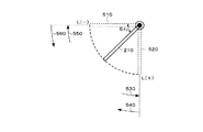
図8はドアの回転範囲を制限する際の回転角の演算例について説明するための図である。ドアの回転範囲は510〜520の間に制限されているものとする。基準位置を510にとって、基準位置510からドア210の回転角をSθyとすると、
L(−)≦Sθy≦L(+) ‥‥(8)
基準位置を510にとっているのでL(−)=0、またL(+)=90として(8)式を満たすようにSθyの値を求める。本実施の形態ではドア210が530の方向に回転して回転角SθyがL(+)に達したら、逆向きに反転して540の方向に回転させる。そして再び回転角SθyがL(−)に達したら回転の向きを550から560に反転させる。反転前の回転角をVθy、反転後の角速度をVθy’とすると本実施の形態では、次式のようにして反転後の角速度をVθy’を演算している。
【0074】
Vθy’=hVθy (−1<h<0) ‥‥(9)
なお−1<h<0とすることで、回転の向きの逆転及び反転時の摩擦による回転角速度の減衰の表現を実現している。
【0075】
次に、オブジェクトの回転範囲にある障害物との重複を回避するようにオブジェクトの回転角を制限する例について説明する。
【0076】
図9は2つのドアが近接して存在する場合、それぞれの回転が他方の回転を干渉する場合の回転範囲の制限例について説明するための図である。
【0077】
610と620は、それぞれP1、P2を回転軸として回転可能なドアをy軸方向から見た図である。回転軸P1、P2からドアの端までの距離をそれぞれR1、R2とする。612、622はそれぞれ回転軸P1、P2を中心とする半径R1、R2の円を表しており、この範囲がそれぞれのドアの回転予定範囲である。
【0078】
ところがP1,P2間の距離はR1+R2より短いために、互いに干渉しあう点が生じる。理論的に2つのドア610、620が360度回転可能であるとすると、2つのドアが交差する点630,640(以下「交点」という)を生じるが、実際には630から640を含む円弧で囲まれた部分ではそれぞれのドアの回転が制限されることになる。
【0079】
そこで本実施の形態では、各ドアについて次フレームの理論上の回転角からその配置位置を演算する。そして各ドアから長手方向にのばした直線614と624の交点P3を求める。P1、P3の距離をL1、P2、P3の距離をL2とするとL1≦R1かつL2≦R2が成り立つならば、各ドアの回転角速度を補正する。即ち各ドアの回転速度の理論値がそれぞV1,V2、補正後の回転角速度をV1’,V2’とすれば、
V1’=h1×V1 (−1<h1<0) ‥‥(10)
V2’=h2×V2 (−1<h2<0) ‥‥(11)
このようにすれば、次フレームでは各ドアは回転方向が反転し、角速度の大きさも減衰する。従って、ドアの回転が障害物により制限されて反転し、反転の際の摩擦により速度が減衰する様子の画像を生成することができる。
【0080】
図10〜図13は本実施の形態の動作例を説明するためのフローチャート図である。
【0081】
まず図10を用いて本実施の形態の動作の概要について説明する。本実施の形態では各フレーム毎に次フレームの画像生成に必要な回転角を求める処理を行い(ステップS10〜S30)、求めた回転角に基づきオブジェクトを配置して、当該オブジェクトを含む画像の生成を行っている(ステップS40)。
【0082】
回転角を求める際には、まず回転範囲になにも制限がないとした場合のオブジェクトの回転角(以下、「回転角の理論値」という)を演算する(ステップS10)。そしてオブジェクトの回転特性に応じて設定された回転範囲に回転角が収まるように理論値を補正する処理を行う(ステップS20)。
【0083】
そしてオブジェクトの回転範囲にある障害物との重複を回避するための回転角の補正処理を行う(ステップS30)。
【0084】
次に図11を用いて、図10のステップS10の処理の詳細例について説明する。なおここでは回転するオブジェクトとしてドアを例にとり説明する。
【0085】
ドアに銃弾がヒットしたか否か判断し(ステップS110)、ヒットした場合にはヒットにより発生したドアを回転させる力(T)を以下のようにして求める。(ステップS130〜S160)。
【0086】
まず銃弾による衝撃位置、衝撃ベクトルの大きさ及び方向を求める(ステップS130)。そして図5で説明したように、衝撃ベクトルのxz成分のうち、ドアの回転軌道に対する接戦方向の成分(VD)を求める(ステップS140)。また図6で説明したように、半径方向の基準長(L)と回転中心から衝撃位置までの距離(l)との比(l/L)を求める(ステップS150)。そして本文中の式(1)で示したようにVDとl/Lに基づきドアを回転させる力(T)を求める(ステップS160)。
【0087】
またドアに銃弾がヒットしていない場合にはT=0とする(ステップS120)。
【0088】
次に本文中の式(2)(3)で示したようにTと空気等の抵抗(F(v))から回転角速度aθyを求める(ステップS170)。
【0089】
次に本文中の式(4)で示したようにaθy及び前回の回転角速度Vθy(n-1)から今回の回転角速度Vθy(n)を求める(ステップS180)。
【0090】
そして本文中の式(5)で示したようにVθy及び前回の回転角Sθy(n-1)から今回の回転角Sθy(n)の理論値を求める(ステップS190)。
【0091】
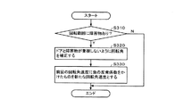
次に図12を用いて、図10のステップS20の処理の詳細例について説明する。
【0092】
前記回転角Sθy(n)の理論値がドアの閉会範囲に基づき設定された制限範囲内にない場合には、回転角が制限範囲内になるように補正する(ステップS220)。
【0093】
そして本文中の式(9)で示したように、前回の回転角速度に負の反発係数を掛けたものを新たな回転角速度とする(ステップS230)。
【0094】
次に図13を用いて、図10のステップS30の処理の詳細例について説明する。
【0095】
図9で説明したように回転範囲内に他のドア等の障害物があった場合には、ドアと障害物が重複しないように回転角を補正する(ステップS320)。
【0096】
そして本文中の式(10)(11)で示したように、前回の回転角速度に負の反発係数を掛けたものを新たな回転角速度とする(ステップS330)。
【0097】
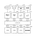
3.ハードウェア構成
次に、本実施形態を実現できるハードウェアの構成の一例について図14を用いて説明する。同図に示すシステムでは、CPU1000、ROM1002、RAM1004、情報記憶媒体1006、音生成IC1008、画像生成IC1010、I/Oポート1012、1014が、システムバス1016により相互にデータ送受信可能に接続されている。そして前記画像生成IC1010にはディスプレイ1018が接続され、音生成IC1008にはスピーカ1020が接続され、I/Oポート1012にはコントロール装置1022が接続され、I/Oポート1014には通信装置1024が接続されている。
【0098】
情報記憶媒体1006は、プログラム、表示物を表現するための画像データ、音データ等が主に格納されるものである。例えば家庭用ゲームシステムではゲームプログラム等を格納する情報記憶媒体としてDVD、ゲームカセット、CDROM等が用いられる。また業務用ゲームシステムではROM等のメモリが用いられ、この場合には情報記憶媒体1006はROM1002になる。
【0099】
コントロール装置1022はゲームコントローラ、操作パネル等に相当するものであり、プレーヤがゲーム進行に応じて行う判断の結果をシステム本体に入力するための装置である。
【0100】
情報記憶媒体1006に格納されるプログラム、ROM1002に格納されるシステムプログラム(システム本体の初期化情報等)、コントロール装置1022によって入力される信号等に従って、CPU1000はシステム全体の制御や各種データ処理を行う。RAM1004はこのCPU1000の作業領域等として用いられる記憶手段であり、情報記憶媒体1006やROM1002の所与の内容、あるいはCPU1000の演算結果等が格納される。また本実施形態を実現するための論理的な構成を持つデータ構造は、このRAM又は情報記憶媒体上に構築されることになる。
【0101】
更に、この種のシステムには音生成IC1008と画像生成IC1010とが設けられていてゲーム音やゲーム画像の好適な出力が行えるようになっている。音生成IC1008は情報記憶媒体1006やROM1002に記憶される情報に基づいて効果音やバックグラウンド音楽等のゲーム音を生成する集積回路であり、生成されたゲーム音はスピーカ1020によって出力される。また、画像生成IC1010は、RAM1004、ROM1002、情報記憶媒体1006等から送られる画像情報に基づいてディスプレイ1018に出力するための画素情報を生成する集積回路である。なおディスプレイ1018として、いわゆるヘッドマウントディスプレイ(HMD)と呼ばれるものを使用することもできる。
【0102】
また、通信装置1024は画像生成システム内部で利用される各種の情報を外部とやりとりするものであり、他の画像生成システムと接続されてゲームプログラムに応じた所与の情報を送受したり、通信回線を介してゲームプログラム等の情報を送受することなどに利用される。
【0103】
そして図1〜図13で説明した種々の処理は、プログラムやデータなどの情報を格納した情報記憶媒体1006、この情報記憶媒体1006からの情報等に基づいて動作するCPU1000、画像生成IC1010或いは音生成IC1008等によって実現される。なお画像生成IC1010、音生成IC1008等で行われる処理は、CPU1000あるいは汎用のDSP等によりソフトウェア的に行ってもよい。
【0104】
図1に示すような業務用ゲームシステムに本実施形態を適用した場合には、内蔵されるシステムボード(サーキットボード)1106に対して、CPU、画像生成IC、音生成IC等が実装される。そして、本実施形態の処理(本発明の手段)を実行(実現)するための情報は、システムボード1106上の情報記憶媒体である半導体メモリ1108に格納される。以下、この情報を格納情報と呼ぶ。
【0105】
図15(A)に、本実施形態を家庭用のゲームシステムに適用した場合の例を示す。プレーヤはディスプレイ1200に映し出されたゲーム画像を見ながら、ゲームコントローラ1202、1204を操作してゲームを楽しむ。この場合、上記格納情報は、本体システムに着脱自在な情報記憶媒体であるDVD1206、メモリーカード1208、1209等に格納されている。
【0106】
図15(B)に、ホスト装置1300と、このホスト装置1300と通信回線(LANのような小規模ネットワークや、インターネットのような広域ネットワーク)1302を介して接続される端末1304-1〜1304-nとを含む画像生成システムに本実施形態を適用した場合の例を示す。この場合、上記格納情報は、例えばホスト装置1300が制御可能な磁気ディスク装置、磁気テープ装置、半導体メモリ等の情報記憶媒体1306に格納されている。端末1304-1〜1304-nが、CPU、画像生成IC、音処理ICを有し、スタンドアロンでゲーム画像、ゲーム音を生成できるものである場合には、ホスト装置1300からは、ゲーム画像、ゲーム音を生成するためのゲームプログラム等が端末1304-1〜1304-nに配送される。一方、スタンドアロンで生成できない場合には、ホスト装置1300がゲーム画像、ゲーム音を生成し、これを端末1304-1〜1304-nに伝送し端末において出力することになる。
【0107】
なお、図15(B)の構成の場合に、本発明の処理を、ホスト装置(サーバー)と端末とで分散して処理するようにしてもよい。また、本発明を実現するための上記格納情報を、ホスト装置(サーバー)の情報記憶媒体と端末の情報記憶媒体に分散して格納するようにしてもよい。
【0108】
また通信回線に接続する端末は、家庭用ゲームシステムであってもよいし業務用ゲームシステムであってもよい。そして、業務用ゲームシステムを通信回線に接続する場合には、業務用ゲームシステムとの間で情報のやり取りが可能であると共に家庭用ゲームシステムとの間でも情報のやり取りが可能な携帯型情報記憶装置(メモリーカード、携帯型ゲーム機)を用いることが望ましい。
【0109】
なお本発明は、上記実施形態で説明したものに限らず、種々の変形実施が可能である。
【0110】
例えば本実施の形態では、ドアのように所定の範囲に回転範囲が制限されているオブジェクトを例にとり説明したがこれに限られない。図16に示す回転いすのように、360度回転可能なオブジェクトの場合でもよい。また例えば電気スタンドのようなT字型のオブジェクトが衝撃を受けて回転する場合でもよい。
【0111】
また本実施の形態では、回転軸がY軸と平行な場合を例に取り説明したがこれに限られない。回転軸が3軸のいずれかと平行でない場合でもよい。
【0112】
また本実施の形態では、オブジェクトに加わる衝撃として銃弾を例に取り説明したがこれに限られない。
【0113】
また本実施の形態では回転軸の回りを回転するオブジェクトを例にとり説明したがこれに限られない。回転中心の回りを回転するオブジェクトの回転動作にも適用可能である。
【0114】
また本実施の形態では、衝撃が一回の場合の回転動作について説明したがこれに限られない。連続して複数の衝撃が加わった場合の回転動作にも適用可能である。
【0115】
また本発明はガンゲーム以外にも種々のゲーム(ガンゲーム以外のシューティングゲーム、格闘ゲーム、ロボット対戦ゲーム、スポーツゲーム、競争ゲーム、ロールプレイングゲーム、音楽演奏ゲーム、ダンスゲーム等)に適用できる。
【0116】
また本発明は、業務用ゲームシステム、家庭用ゲームシステム、多数のプレーヤが参加する大型アトラクションシステム、シミュレータ、マルチメディア端末、画像生成システム、ゲーム画像を生成するシステムボード等の種々の画像生成システムに適用できる。
【図面の簡単な説明】
【図1】本実施形態を業務用ゲームシステムに適用した場合の構成例を示す図である。
【図2】本実施形態の画像生成システムのブロック図の例である。
【図3】本実施形態のゲーム画像の例である。
【図4】ドアの回転角について説明するための図である。
【図5】銃弾による衝撃ベクトルとドアの回転に寄与する力の関係について説明するための図である。
【図6】衝撃位置の回転中心からの距離lとドアを回転させる力Tとの関係について説明するための図である。
【図7】回転開始位置とn−1フレーム目及びnフレーム目の回転角との関係を説明するための図である。
【図8】ドアの回転範囲を制限する際の回転角の演算例について説明するための図である。
【図9】2つのドアが近接して存在する場合、それぞれの回転が他方の回転を干渉する場合の回転範囲の制限例について説明するための図である。
【図10】本実施の形態の動作例を説明するためのフローチャート図である。
【図11】本実施の形態の動作例を説明するためのフローチャート図である。
【図12】本実施の形態の動作例を説明するためのフローチャート図である。
【図13】本実施の形態の動作例を説明するためのフローチャート図である。
【図14】本実施形態を実現できるハードウェアの構成の一例を示す図である。
【図15】図15(A)、(B)は、本実施形態が適用される種々の形態のシステムの例を示す図である。
【図16】本発明が適用可能な他のオブジェクトの一例である。
【符号の説明】
100 処理部
110 ゲーム演算部
112 ヒットチェック部
114 衝撃情報演算部
116 回転位置決定情報演算部
130 操作部
140 記憶部
150 情報記憶媒体
160 画像生成部
162 表示部
170 音生成部
172 音出力部
174 通信部
176 I/F部
180 メモリーカード[0001]
BACKGROUND OF THE INVENTION
The present invention relates to an image generation system and an information storage medium.
[0002]
[Background Art and Problems to be Solved by the Invention]
2. Description of the Related Art Conventionally, an image generation system that generates an image that can be seen from a given viewpoint in an object space that is a virtual three-dimensional space is known, and is popular as being able to experience so-called virtual reality. Taking an image generation system that can enjoy a gun game as an example, a player (operator) uses a gun-type controller (shooting device) imitating a gun or the like to display enemy characters (screened on the screen). Enjoy 3D games by shooting target objects such as objects.
[0003]
In such an image generation system, it is an important technical problem to generate a more realistic image in order to improve the player's virtual reality. Therefore, it is desirable to be able to express more realistically what is rotated when an impact such as a bullet is applied, such as a door or a rotating chair.
[0004]
For example, when a door or a rotating chair receives a bullet, it should rotate at different speeds and sizes depending on the location of the bullet and the direction and size of the bullet.
[0005]
However, in conventional image generation systems, when a bullet hits a door or a rotating chair, only an image of a rotation operation prepared in advance is generated. For this reason, the doors and rotating chairs in the game screen will rotate the same regardless of where the bullet hits, and from what direction the bullet hits, making the game image monotonous lacking arity. It was.
[0006]
The present invention has been made in view of such a conventional problem, and an object of the present invention is to realistically display an image of an object that rotates according to the impact position and the magnitude and direction of the impact with a smaller amount of data and a calculation load. It is an object of the present invention to provide an image generation system and an information storage medium that can be expressed as follows.
[0007]
[Means for Solving the Problems]
When an impact vector is applied to an object having a given rotation axis or center of rotation, the image generation system of the present invention includes means for calculating the impact position and the impact vector applied to the object, the impact position, Means for calculating rotational position determination information necessary for determining the rotational position of the object based on the distance to the rotational axis or rotational center of the object and the impact vector, and arrangement based on the rotational position determination information And means for generating an image including the formed object.
[0008]
The information storage medium according to the present invention is an information storage medium that can be used by a computer, and includes information (program or data) for realizing (executing) the above means. A program according to the present invention is a program (including a program embodied in a carrier wave) usable by a computer, and includes a processing routine for realizing (executing) the above means.
[0009]
Here, the information necessary for determining the rotation position of the object may be a rotation angle from the reference position or the position of the previous frame, or a rotation speed, a rotation acceleration, or the like.
[0010]
According to the present invention, since the impact position and the magnitude and direction of the impact vector applied to the object can be calculated in real time and an image of the rotating object can be generated based on these, the impact position and the magnitude and direction of the impact can be determined. It is possible to generate a realistic image that performs the reflected rotation.
[0011]
The image generation system, the information storage medium, and the program according to the present invention include a torque for rotating the object around the rotation axis or the rotation center based on a predetermined distance between the rotation axis or the rotation center and the impact position and an impact vector. The rotational position determination information is calculated based on the torque.
[0012]
In the present invention, since a rotation axis or a rotation center is set in advance for an object having a possibility of rotation, a torque corresponding to the impact position can be easily calculated. Therefore, it is possible to generate a high-reality image reflecting the impact plate and the magnitude and direction of the impact with a small calculation load.
[0013]
Further, the image generation system, the information storage medium, and the program according to the present invention limit the rotation range of the object so that the rotation range of the object falls within a rotation range set according to the rotation characteristic of the object. And
[0014]
The limitation of the rotation range may be, for example, a method of adjusting the rotation angle or a method of adjusting the rotation angular velocity.
[0015]
The present invention is convenient when generating an image of an object that rotates within a predetermined range, such as a door.
[0016]
The image generation system, information storage medium, and program according to the present invention are characterized in that, when there is an obstacle in the rotation range of the object, the rotation range of the object is limited to a range that does not overlap with the obstacle.
[0017]
The limitation of the rotation range may be, for example, a method of adjusting the rotation angle or a method of adjusting the rotation angular velocity. The obstacle may be a stationary object or a moving object.
[0018]
According to the present invention, an image whose rotation is restricted by an obstacle can be generated, and thus a more realistic rotation image can be generated.
[0019]
The image generation system, the information storage medium, and the program according to the present invention are characterized in that when the rotation angle of the object reaches a limit range, the rotation direction of the object is changed so as to rotate in the reverse direction.
[0020]
According to the present invention, it is possible to generate an image of an object that is restricted in rotation and rotates in the opposite direction. In addition, an image of an object that reciprocates like a pendulum within a limited range can be generated.
[0021]
The image generation system, information storage medium, and program according to the present invention are characterized by attenuating the magnitude of the rotational angular velocity of an object based on at least one of the passage of game time and the occurrence of a collision with another object. .
[0022]
The rotational motion of an object in the real world is attenuated by various resistance elements such as air resistance and collision resistance. According to the present invention, it is possible to easily represent a state in which each rotation speed is attenuated by air resistance or the like by attenuating the rotation angular velocity of the object as the game time elapses.
[0023]
In addition, by attenuating the rotational angular velocity of the object due to the occurrence of an impact, it is possible to simply express how the rotation is attenuated by impact friction.
[0024]
The calculation load can be further reduced by setting the attenuation ratio to a predetermined value in advance.
[0025]
DETAILED DESCRIPTION OF THE INVENTION
Hereinafter, preferred embodiments of the present invention will be described with reference to the drawings. Hereinafter, a case where the present invention is applied to a gun game (shooting game) using a gun-type controller will be described as an example. However, the present invention is not limited to this and can be applied to various games.
[0026]
1. Configuration FIG. 1 shows a configuration example when the present embodiment is applied to an arcade game system.
[0027]
The
[0028]
In particular, when the gun-
[0029]
The shot hit position (landing position) may be detected by providing an optical sensor in the gun-
[0030]
FIG. 2 shows an example of a block diagram of the present embodiment. In this figure, the present embodiment may include at least the processing unit 100 (or may include the
[0031]
Here, the
[0032]
The
[0033]
The
[0034]
An information storage medium (storage medium usable by a computer) 150 stores information such as programs and data, and functions thereof are an optical disk (CD, DVD), a magneto-optical disk (MO), a magnetic disk, and a hard disk. It can be realized by hardware such as a magnetic tape or a semiconductor memory (ROM). The
[0035]
Part or all of the information stored in the
[0036]
The
[0037]
The
[0038]
The
[0039]
Note that information for realizing the processing of the present invention (this embodiment) may be distributed from the information storage medium of the host device (server) to the
[0040]
Further, part or all of the functions of the
[0041]
The I /
[0042]
The
[0043]
Here, the game calculation unit 110 accepts coins (costs), sets various modes, progresses the game, sets the selection screen, and positions and rotation angles (X, Y or Z-axis rotation angle), viewpoint position and line-of-sight angle determination process, object motion playback or generation process, object placement process in object space, hit check process, game results (results, results) Various game calculation processes such as a calculation process, a process for a plurality of players to play in a common game space, or a game over process, operation data from the
[0044]
The game calculation unit 110 includes a
[0045]
Here, the
[0046]
The impact
[0047]
The rotational position determination
[0048]
The
[0049]
Here, a torque for rotating the object around the rotation axis or the rotation center is obtained based on a predetermined distance between the rotation axis or rotation center and the impact position and an impact vector, and the rotational position determination information is calculated based on the torque. You may do it.
[0050]
In addition, the rotation range of the object may be limited so that the rotation range of the object falls within a rotation range set according to the rotation characteristics of the object, or there is an obstacle in the rotation range of the object In addition, the rotation range of the object may be limited to a range that does not overlap with the obstacle. When the rotation angle of the object reaches the limit range, the rotation direction of the object may be changed so as to rotate in the reverse direction.
[0051]
Further, the magnitude of the rotational angular velocity of the object may be attenuated based on at least one of the passage of the game time and the occurrence of a collision with another object.
[0052]
Note that the image generation system of the present embodiment may be a system dedicated to the single player mode in which only one player can play, or not only the single player mode but also a multiplayer mode in which a plurality of players can play. The system may also be provided.
[0053]
Further, when a plurality of players play, game images and game sounds to be provided to the plurality of players may be generated using one terminal, or connected via a network (transmission line, communication line) or the like. Alternatively, it may be generated using a plurality of terminals.
[0054]
2. Features and operations of the present embodiment The first feature of the present embodiment is that when an impact vector is applied to an object having a given rotation axis or rotation center, the impact position and the rotation axis of the object. Alternatively, the rotation angle of the object is calculated based on the distance from the rotation center and the magnitude and direction of the impact vector.
[0055]
FIG. 3 shows an example of a game image according to the present embodiment, and shows a state in which a bullet hits the vicinity of 710 of the
[0056]
A method for calculating the rotation angle when the door rotates upon receiving a bullet will be described with reference to FIGS.
[0057]
FIG. 4 is a diagram for explaining a desired rotation angle of the door. The
[0058]
FIG. 5 is a diagram for explaining the relationship between the impact vector due to the bullet and the force contributing to the rotation of the door. This figure is an xz plan view showing a state where a
[0059]
Here, 230 is the position where the
[0060]
FIG. 6 is a diagram for explaining the relationship between the distance l from the
[0061]
The force T for rotating the rotation of the door is L for the reference length in the radial direction (length from the rotation axis to the end of the door), VD for the xz component of the impact vector, and l for the distance between the
[0062]
T = VD × l / L (1)
Here, when the force for rotating the door is F and the proportionality constant is k, F is expressed as a function of T by the following equation.
[0063]
F (T) = kT (2)
Since generally the force is expressed by the product of mass and acceleration, rotation angular acceleration A.theta. Y door can be expressed by the following equation.
[0064]
aθ y = F (T) + F (v) (3)
Here, F (v) is a resistance of air or the like.
[0065]
In addition, for the sake of simplicity, aθ y is considered as angular acceleration per frame, and the rotational angular velocity of the door in the previous frame is Vθ y (n-1) and the rotational angular velocity of the door this time is Vθ y (n) . The following equation holds.
[0066]
Vθ y (n) = Vθ y (n-1) + aθ y (4)
FIG. 7 is a diagram for explaining the relationship between the rotation start position and the rotation angles of the (n−1) th frame and the nth frame. 410 is the door rotation start position, 420 is the position of the door of the (n-1) th frame, and 430 is the position of the door of the nth frame.
[0067]
As shown in FIG. 7, when the rotation angle of the
[0068]
Sθ y (n) = Sθ y (n-1) + Vθ y (5)
Here, in the next frame hit with a bullet, n = 1, and the following expressions hold for (4) and (5).
[0069]
Vθ y (1) = aθ y (6)
Sθ y (1) = Vθ y (7)
Therefore, in the next frame hit by the bullet, Sθ y (1) = aθ y is satisfied , and the door is arranged at a position rotated by aθ y .
[0070]
By doing in this way, the image of the door which rotates reflecting the magnitude | size and direction of an impact position and an impact vector can be produced | generated.
[0071]
Furthermore, from the next frame, when a new impact is not applied, since F (T) = 0 in (3), aθ y = F (v). Since this is a air resistance becomes the Vθ y (2) = Vθ y (1) + aθ y which is obtained in (4), Vθ y (1 )> Vθ y (2). The same applies to the following frames.
Vθ y (1) >...> Vθ y (n-1) > Vθ y (n)
Thus, the angular velocity of rotation gradually decreases. Therefore, it is possible to easily express on the game screen how the rotation of the door, which was initially strong, gradually attenuates.
[0072]
Next, an example of limiting the rotation range of the object in the present embodiment will be described. In this embodiment, since the rotation angle calculation target is a door, it is unnatural to rotate within a range of 360 degrees. Therefore, the rotation angle is limited so that the door rotates within a predetermined range.
[0073]
FIG. 8 is a diagram for explaining a calculation example of the rotation angle when limiting the rotation range of the door. The rotation range of the door is limited to between 510 and 520. If the reference position is 510 and the rotation angle of the
L (−) ≦ Sθ y ≦ L (+) (8)
Since the reference position is 510, L (−) = 0 and L (+) = 90, and the value of Sθ y is obtained so as to satisfy the expression (8). When the rotation angle S.theta y rotating in the direction of the
[0074]
Vθ y ′ = hVθ y (−1 <h <0) (9)
By setting -1 <h <0, the expression of attenuation of the rotational angular velocity due to the reversal of the direction of rotation and the friction during reversal is realized.
[0075]
Next, an example in which the rotation angle of the object is limited so as to avoid overlapping with an obstacle in the rotation range of the object will be described.
[0076]
FIG. 9 is a diagram for explaining a restriction example of the rotation range when two doors are close to each other and each rotation interferes with the other rotation.
[0077]
610 and 620 are views of the door that can rotate about P 1 and P 2 as rotation axes, respectively, as seen from the y-axis direction. The distances from the rotation axes P 1 and P 2 to the end of the door are R 1 and R 2 , respectively.
[0078]
However, since the distance between P 1 and P 2 is shorter than R 1 + R 2, points that interfere with each other occur. Theoretically, if the two
[0079]
Therefore, in the present embodiment, the position of each door is calculated from the theoretical rotation angle of the next frame. Then, an intersection point P 3 between
V 1 '= h 1 × V 1 (-1 <h 1 <0) (10)
V 2 '= h 2 × V 2 (−1 <h 2 <0) (11)
In this way, in the next frame, the rotation direction of each door is reversed, and the magnitude of the angular velocity is also attenuated. Therefore, it is possible to generate an image in which the rotation of the door is reversed by being restricted by the obstacle and the speed is attenuated by the friction during the reversal.
[0080]
10 to 13 are flowcharts for explaining an operation example of the present embodiment.
[0081]
First, the outline of the operation of the present embodiment will be described with reference to FIG. In the present embodiment, a process for obtaining a rotation angle necessary for image generation of the next frame is performed for each frame (steps S10 to S30), an object is arranged based on the obtained rotation angle, and an image including the object is generated. (Step S40).
[0082]
When obtaining the rotation angle, first, the rotation angle of the object (hereinafter referred to as “theoretical value of the rotation angle”) when there is no limitation on the rotation range is calculated (step S10). Then, a process of correcting the theoretical value so that the rotation angle is within the rotation range set according to the rotation characteristic of the object is performed (step S20).
[0083]
Then, a rotation angle correction process is performed to avoid overlapping with an obstacle in the rotation range of the object (step S30).
[0084]
Next, a detailed example of the process in step S10 in FIG. 10 will be described with reference to FIG. Here, a description will be given taking a door as an example of a rotating object.
[0085]
It is determined whether or not a bullet has hit the door (step S110), and if it hits, the force (T) for rotating the door generated by the hit is obtained as follows. (Steps S130 to S160).
[0086]
First, the impact position by the bullet and the magnitude and direction of the impact vector are obtained (step S130). Then, as described with reference to FIG. 5, the component (VD) in the contact direction with respect to the rotation trajectory of the door among the xz components of the impact vector is obtained (step S140). Further, as described with reference to FIG. 6, the ratio (l / L) between the reference length (L) in the radial direction and the distance (l) from the center of rotation to the impact position is obtained (step S150). Then, as shown by the expression (1) in the text, a force (T) for rotating the door is obtained based on VD and 1 / L (step S160).
[0087]
If no bullet hits the door, T = 0 (step S120).
[0088]
Next, as shown in the equations (2) and (3) in the text, the rotational angular velocity aθ y is obtained from T and the resistance (F (v)) of air or the like (step S170).
[0089]
Next, the current rotational angular velocity Vθ y (n) is obtained from aθ y and the previous rotational angular velocity Vθ y (n−1) as shown by the equation (4) in the text (step S180).
[0090]
Then, as shown by the equation (5) in the text, the theoretical value of the current rotation angle Sθ y (n) is obtained from Vθ y and the previous rotation angle Sθ y (n−1) (step S190).
[0091]
Next, a detailed example of the process in step S20 in FIG. 10 will be described with reference to FIG.
[0092]
If the theoretical value of the rotation angle Sθy (n) is not within the limit range set based on the closing range of the door, the rotation angle is corrected to be within the limit range (step S220).
[0093]
Then, as indicated by the equation (9) in the text, a value obtained by multiplying the previous rotational angular velocity by the negative restitution coefficient is set as a new rotational angular velocity (step S230).
[0094]
Next, a detailed example of the process of step S30 in FIG. 10 will be described with reference to FIG.
[0095]
As described with reference to FIG. 9, when there is an obstacle such as another door within the rotation range, the rotation angle is corrected so that the door does not overlap the obstacle (step S320).
[0096]
Then, as indicated by the equations (10) and (11) in the text, a value obtained by multiplying the previous rotational angular velocity by a negative restitution coefficient is set as a new rotational angular velocity (step S330).
[0097]
3. Hardware Configuration Next, an example of a hardware configuration capable of realizing the present embodiment will be described with reference to FIG. In the system shown in the figure, a
[0098]
The
[0099]
The
[0100]
In accordance with a program stored in the
[0101]
Furthermore, this type of system is provided with a
[0102]
The
[0103]
Various processes described with reference to FIGS. 1 to 13 include an
[0104]
When this embodiment is applied to an arcade game system as shown in FIG. 1, a CPU, an image generation IC, a sound generation IC, and the like are mounted on a built-in system board (circuit board) 1106. Information for executing (implementing) the processing (means of the present invention) of this embodiment is stored in a
[0105]
FIG. 15A shows an example in which the present embodiment is applied to a home game system. The player enjoys the game by operating the
[0106]
FIG. 15B shows a
[0107]
In the case of the configuration shown in FIG. 15B, the processing of the present invention may be distributed between the host device (server) and the terminal. The storage information for realizing the present invention may be distributed and stored in the information storage medium of the host device (server) and the information storage medium of the terminal.
[0108]
The terminal connected to the communication line may be a home game system or an arcade game system. And, when the arcade game system is connected to a communication line, portable information storage that can exchange information with the arcade game system and exchange information with the home game system. It is desirable to use a device (memory card, portable game machine).
[0109]
The present invention is not limited to that described in the above embodiment, and various modifications can be made.
[0110]
For example, in the present embodiment, the object whose rotation range is limited to a predetermined range such as a door has been described as an example, but the present invention is not limited to this. An object that can rotate 360 degrees, such as a rotating chair shown in FIG. 16, may be used. Further, for example, a T-shaped object such as a desk lamp may be rotated by receiving an impact.
[0111]
In this embodiment, the case where the rotation axis is parallel to the Y axis has been described as an example, but the present invention is not limited to this. The rotation axis may not be parallel to any of the three axes.
[0112]
In the present embodiment, a bullet is taken as an example of an impact applied to an object, but the present invention is not limited to this.
[0113]
In the present embodiment, the object rotating around the rotation axis has been described as an example, but the present invention is not limited to this. The present invention can also be applied to a rotation operation of an object that rotates around the rotation center.
[0114]
In the present embodiment, the rotation operation in the case of one impact has been described, but the present invention is not limited to this. The present invention can also be applied to a rotating operation when a plurality of impacts are continuously applied.
[0115]
In addition to the gun game, the present invention can be applied to various games (shooting games other than gun games, fighting games, robot fighting games, sports games, competition games, role playing games, music playing games, dance games, etc.).
[0116]
The present invention also relates to various image generation systems such as a business game system, a home game system, a large attraction system in which a large number of players participate, a simulator, a multimedia terminal, an image generation system, and a system board for generating game images. Applicable.
[Brief description of the drawings]
FIG. 1 is a diagram showing a configuration example when the present embodiment is applied to an arcade game system.
FIG. 2 is an example of a block diagram of an image generation system according to the present embodiment.
FIG. 3 is an example of a game image of the present embodiment.
FIG. 4 is a diagram for explaining a rotation angle of a door.
FIG. 5 is a diagram for explaining a relationship between an impact vector due to a bullet and a force contributing to rotation of a door.
FIG. 6 is a diagram for explaining the relationship between the distance l from the rotation center of the impact position and the force T for rotating the door.
FIG. 7 is a diagram for explaining a relationship between a rotation start position and rotation angles of the (n−1) th frame and the nth frame.
FIG. 8 is a diagram for explaining a calculation example of a rotation angle when limiting the rotation range of the door.
FIG. 9 is a diagram for explaining a limiting example of a rotation range when two doors are close to each other and each rotation interferes with the other rotation;
FIG. 10 is a flowchart for explaining an operation example of the present embodiment;
FIG. 11 is a flowchart for explaining an operation example of the present embodiment;
FIG. 12 is a flowchart for explaining an operation example of the present embodiment;
FIG. 13 is a flowchart for explaining an operation example of the present embodiment;
FIG. 14 is a diagram illustrating an example of a hardware configuration capable of realizing the present embodiment.
FIGS. 15A and 15B are diagrams illustrating examples of various forms of systems to which the present embodiment is applied.
FIG. 16 is an example of another object to which the present invention is applicable.
[Explanation of symbols]
DESCRIPTION OF
Claims (6)
前記衝撃位置と前記オブジェクトの回転軸又は回転中心との距離及び衝撃ベクトルとに基づいて前記オブジェクトを回転軸又は回転中心の回りに回転させるトルクをもとめ、前記オブジェクトの回転後の位置を決定するために必要な回転位置決定情報を当該トルクに基づき演算する手段と、
前記回転位置決定情報に基づいて配置されたオブジェクトを含む画像を生成する手段と、を含むことを特徴とする画像生成システム。Means for calculating an impact position and an impact vector applied to an object when an impact is applied to an object having a given rotation axis or rotation center;
To determine a position after rotation of the object by obtaining a torque for rotating the object around the rotation axis or center of rotation based on a distance between the impact position and the rotation axis or center of rotation of the object and an impact vector. Means for calculating rotational position determination information necessary for the operation based on the torque;
Means for generating an image including an object arranged based on the rotational position determination information.
前記衝撃位置と前記オブジェクトの回転軸又は回転中心との距離及び衝撃ベクトルとに基づいて、前記オブジェクトの回転後の位置を決定するために必要な回転位置決定情報を演算する手段と、
前記回転位置決定情報に基づいて配置されたオブジェクトを含む画像を生成する手段と、
を含み、
前記回転位置決定情報を演算する手段は、前記オブジェクトの回転角が制限範囲に達したら逆向きに回転するようにオブジェクトの回転の向きを変更することを特徴とする画像生成システム。Means for calculating an impact position and an impact vector applied to an object when an impact is applied to an object having a given rotation axis or rotation center;
Means for calculating rotational position determination information necessary for determining a position after rotation of the object based on a distance and an impact vector between the impact position and the rotation axis or rotation center of the object;
Means for generating an image including an object arranged based on the rotational position determination information;
Including
The image generation system characterized in that the means for calculating the rotational position determination information changes the rotation direction of the object so as to rotate in the reverse direction when the rotation angle of the object reaches a limit range.
前記回転位置決定情報を演算する手段は、前記オブジェクトの回転範囲が、オブジェクトの回転特性に応じて設定された回転範囲に収まるように、オブジェクトの回転範囲を制限することを特徴とする画像生成システム。In any one of Claims 1 thru | or 2 .
The means for calculating the rotation position determination information limits the rotation range of the object so that the rotation range of the object falls within a rotation range set according to the rotation characteristics of the object. .
前記回転位置決定情報を演算する手段は、前記オブジェクトの回転範囲に障害物がある場合に、オブジェクトの回転範囲を障害物と重複しない範囲に制限することを特徴とする画像生成システム。In any one of Claims 1 thru | or 3 ,
The means for calculating the rotational position determination information limits the rotation range of the object to a range that does not overlap with the obstacle when there is an obstacle in the rotation range of the object.
所与の回転軸又は回転中心が設定されているオブジェクトに衝撃が加わった場合に、前記オブジェクトに加わった衝撃位置及び衝撃ベクトルを演算する手段と、
前記衝撃位置と前記オブジェクトの回転軸又は回転中心との距離及び衝撃ベクトルとに基づいて前記オブジェクトを回転軸又は回転中心の回りに回転させるトルクをもとめ、前記オブジェクトの回転後の位置を決定するために必要な回転位置決定情報を当該トルクに基づき演算する手段と、
前記回転位置決定情報に基づいて配置されたオブジェクトを含む画像を生成する手段としてコンピュータを機能させるためのプログラムが記憶されていることを特徴とする情報記憶媒体。A computer-readable information storage medium,
Means for calculating an impact position and an impact vector applied to an object when an impact is applied to an object having a given rotation axis or rotation center;
To determine a position after rotation of the object by obtaining a torque for rotating the object around the rotation axis or center of rotation based on a distance between the impact position and the rotation axis or center of rotation of the object and an impact vector. Means for calculating rotational position determination information necessary for the operation based on the torque;
An information storage medium storing a program for causing a computer to function as means for generating an image including an object arranged based on the rotational position determination information.
所与の回転軸又は回転中心が設定されているオブジェクトに衝撃が加わった場合に、前記オブジェクトに加わった衝撃位置及び衝撃ベクトルを演算する手段と、
前記衝撃位置と前記オブジェクトの回転軸又は回転中心との距離及び衝撃ベクトルとに基づいて、前記オブジェクトの回転後の位置を決定するために必要な回転位置決定情報を演算する手段と、
前記回転位置決定情報に基づいて配置されたオブジェクトを含む画像を生成する手段としてコンピュータを機能させ、
前記回転位置決定情報を演算する手段は、前記オブジェクトの回転角が制限範囲に達したら逆向きに回転するようにオブジェクトの回転の向きを変更するプログラムが記憶されていることを特徴とする情報記憶媒体。A computer-readable information storage medium,
Means for calculating an impact position and an impact vector applied to an object when an impact is applied to an object having a given rotation axis or rotation center;
Means for calculating rotational position determination information necessary for determining a position after rotation of the object based on a distance and an impact vector between the impact position and the rotation axis or rotation center of the object;
Causing a computer to function as a means for generating an image including an object arranged based on the rotational position determination information;
The information storage means characterized in that the means for calculating the rotational position determination information stores a program for changing the direction of rotation of the object so as to rotate in the reverse direction when the rotation angle of the object reaches a limit range. Medium.
Priority Applications (1)
| Application Number | Priority Date | Filing Date | Title |
|---|---|---|---|
| JP21916399A JP4301469B2 (en) | 1999-08-02 | 1999-08-02 | Image generation system and information storage medium |
Applications Claiming Priority (1)
| Application Number | Priority Date | Filing Date | Title |
|---|---|---|---|
| JP21916399A JP4301469B2 (en) | 1999-08-02 | 1999-08-02 | Image generation system and information storage medium |
Publications (3)
| Publication Number | Publication Date |
|---|---|
| JP2001043397A JP2001043397A (en) | 2001-02-16 |
| JP2001043397A5 JP2001043397A5 (en) | 2006-09-21 |
| JP4301469B2 true JP4301469B2 (en) | 2009-07-22 |
Family
ID=16731199
Family Applications (1)
| Application Number | Title | Priority Date | Filing Date |
|---|---|---|---|
| JP21916399A Expired - Lifetime JP4301469B2 (en) | 1999-08-02 | 1999-08-02 | Image generation system and information storage medium |
Country Status (1)
| Country | Link |
|---|---|
| JP (1) | JP4301469B2 (en) |
Families Citing this family (4)
| Publication number | Priority date | Publication date | Assignee | Title |
|---|---|---|---|---|
| JP3760347B2 (en) | 2002-07-30 | 2006-03-29 | 株式会社光栄 | Program, recording medium, game character drawing method, and game apparatus |
| JP4580742B2 (en) | 2004-11-30 | 2010-11-17 | 任天堂株式会社 | GAME PROGRAM AND GAME DEVICE |
| JP4740644B2 (en) * | 2005-05-11 | 2011-08-03 | 任天堂株式会社 | Image processing program and image processing apparatus |
| JP4971908B2 (en) | 2007-08-24 | 2012-07-11 | 任天堂株式会社 | Information processing program and information processing apparatus |
-
1999
- 1999-08-02 JP JP21916399A patent/JP4301469B2/en not_active Expired - Lifetime
Also Published As
| Publication number | Publication date |
|---|---|
| JP2001043397A (en) | 2001-02-16 |
Similar Documents
| Publication | Publication Date | Title |
|---|---|---|
| JP4301471B2 (en) | Image generation system and information storage medium | |
| JP3707995B2 (en) | GAME SYSTEM AND INFORMATION STORAGE MEDIUM | |
| US20030040362A1 (en) | Image generation method, program, and information storage medium | |
| US7119817B1 (en) | Image generating system and program | |
| US20020190981A1 (en) | Image generation device and information storage medium | |
| JP4433579B2 (en) | GAME SYSTEM AND INFORMATION STORAGE MEDIUM | |
| JP4301469B2 (en) | Image generation system and information storage medium | |
| JP2001006000A (en) | Image generation system and information storage medium | |
| JP4278070B2 (en) | Image generation system and information storage medium | |
| JP2000288248A (en) | Game device and information storage medium | |
| JP4278071B2 (en) | Image generation system and information storage medium | |
| JP3818774B2 (en) | Game device | |
| JP2008173491A (en) | Image generator and information storage medium | |
| JP4114825B2 (en) | Image generating apparatus and information storage medium | |
| JP2006268676A (en) | Program, information storage medium and image generation system | |
| JP2003210837A (en) | Image-generating system, program, and information- storage medium | |
| JP4251589B2 (en) | Image generation system and information storage medium | |
| JP4508918B2 (en) | Image generation system and information storage medium | |
| JP4420729B2 (en) | Program, information storage medium, and image generation system | |
| US7142212B1 (en) | Image generation system and program | |
| JPH11259687A (en) | Image generating device and information storage medium | |
| JP3686069B2 (en) | Program, information storage medium, and image generation system | |
| JP2004057797A (en) | Game system, program, and information storage medium | |
| JP3990050B2 (en) | GAME DEVICE AND INFORMATION STORAGE MEDIUM | |
| JP2011255114A (en) | Program, information storage medium, and image generation system |
Legal Events
| Date | Code | Title | Description |
|---|---|---|---|
| A521 | Written amendment |
Free format text: JAPANESE INTERMEDIATE CODE: A523 Effective date: 20060728 |
|
| A621 | Written request for application examination |
Free format text: JAPANESE INTERMEDIATE CODE: A621 Effective date: 20060728 |
|
| A131 | Notification of reasons for refusal |
Free format text: JAPANESE INTERMEDIATE CODE: A131 Effective date: 20081029 |
|
| A521 | Written amendment |
Free format text: JAPANESE INTERMEDIATE CODE: A523 Effective date: 20081225 |
|
| A131 | Notification of reasons for refusal |
Free format text: JAPANESE INTERMEDIATE CODE: A131 Effective date: 20090128 |
|
| A521 | Written amendment |
Free format text: JAPANESE INTERMEDIATE CODE: A523 Effective date: 20090326 |
|
| TRDD | Decision of grant or rejection written | ||
| A01 | Written decision to grant a patent or to grant a registration (utility model) |
Free format text: JAPANESE INTERMEDIATE CODE: A01 Effective date: 20090415 |
|
| A01 | Written decision to grant a patent or to grant a registration (utility model) |
Free format text: JAPANESE INTERMEDIATE CODE: A01 |
|
| A61 | First payment of annual fees (during grant procedure) |
Free format text: JAPANESE INTERMEDIATE CODE: A61 Effective date: 20090417 |
|
| FPAY | Renewal fee payment (event date is renewal date of database) |
Free format text: PAYMENT UNTIL: 20120501 Year of fee payment: 3 |
|
| R150 | Certificate of patent or registration of utility model |
Ref document number: 4301469 Country of ref document: JP Free format text: JAPANESE INTERMEDIATE CODE: R150 Free format text: JAPANESE INTERMEDIATE CODE: R150 |
|
| FPAY | Renewal fee payment (event date is renewal date of database) |
Free format text: PAYMENT UNTIL: 20120501 Year of fee payment: 3 |
|
| FPAY | Renewal fee payment (event date is renewal date of database) |
Free format text: PAYMENT UNTIL: 20120501 Year of fee payment: 3 |
|
| FPAY | Renewal fee payment (event date is renewal date of database) |
Free format text: PAYMENT UNTIL: 20130501 Year of fee payment: 4 |
|
| R250 | Receipt of annual fees |
Free format text: JAPANESE INTERMEDIATE CODE: R250 |
|
| FPAY | Renewal fee payment (event date is renewal date of database) |
Free format text: PAYMENT UNTIL: 20130501 Year of fee payment: 4 |
|
| FPAY | Renewal fee payment (event date is renewal date of database) |
Free format text: PAYMENT UNTIL: 20140501 Year of fee payment: 5 |
|
| R250 | Receipt of annual fees |
Free format text: JAPANESE INTERMEDIATE CODE: R250 |
|
| R250 | Receipt of annual fees |
Free format text: JAPANESE INTERMEDIATE CODE: R250 |
|
| R250 | Receipt of annual fees |
Free format text: JAPANESE INTERMEDIATE CODE: R250 |
|
| S531 | Written request for registration of change of domicile |
Free format text: JAPANESE INTERMEDIATE CODE: R313531 |
|
| S533 | Written request for registration of change of name |
Free format text: JAPANESE INTERMEDIATE CODE: R313533 |
|
| R360 | Written notification for declining of transfer of rights |
Free format text: JAPANESE INTERMEDIATE CODE: R360 |
|
| R360 | Written notification for declining of transfer of rights |
Free format text: JAPANESE INTERMEDIATE CODE: R360 |
|
| R370 | Written measure of declining of transfer procedure |
Free format text: JAPANESE INTERMEDIATE CODE: R370 |
|
| R350 | Written notification of registration of transfer |
Free format text: JAPANESE INTERMEDIATE CODE: R350 |
|
| S531 | Written request for registration of change of domicile |
Free format text: JAPANESE INTERMEDIATE CODE: R313531 |
|
| R350 | Written notification of registration of transfer |
Free format text: JAPANESE INTERMEDIATE CODE: R350 |
|
| R250 | Receipt of annual fees |
Free format text: JAPANESE INTERMEDIATE CODE: R250 |
|
| R250 | Receipt of annual fees |
Free format text: JAPANESE INTERMEDIATE CODE: R250 |
|
| R250 | Receipt of annual fees |
Free format text: JAPANESE INTERMEDIATE CODE: R250 |
|
| EXPY | Cancellation because of completion of term |