JP3686069B2 - Program, information storage medium, and image generation system - Google Patents
Program, information storage medium, and image generation system Download PDFInfo
- Publication number
- JP3686069B2 JP3686069B2 JP2004014934A JP2004014934A JP3686069B2 JP 3686069 B2 JP3686069 B2 JP 3686069B2 JP 2004014934 A JP2004014934 A JP 2004014934A JP 2004014934 A JP2004014934 A JP 2004014934A JP 3686069 B2 JP3686069 B2 JP 3686069B2
- Authority
- JP
- Japan
- Prior art keywords
- cursor
- hitting
- axis direction
- coordinate axis
- point
- Prior art date
- Legal status (The legal status is an assumption and is not a legal conclusion. Google has not performed a legal analysis and makes no representation as to the accuracy of the status listed.)
- Expired - Lifetime
Links
- 238000012545 processing Methods 0.000 claims description 85
- 238000000034 method Methods 0.000 claims description 56
- 230000008569 process Effects 0.000 claims description 41
- 230000033001 locomotion Effects 0.000 claims description 17
- 239000003550 marker Substances 0.000 description 27
- 230000006870 function Effects 0.000 description 13
- 235000013372 meat Nutrition 0.000 description 13
- 238000004891 communication Methods 0.000 description 10
- 238000010586 diagram Methods 0.000 description 8
- 238000004364 calculation method Methods 0.000 description 6
- 238000004088 simulation Methods 0.000 description 5
- 230000009466 transformation Effects 0.000 description 5
- 238000003825 pressing Methods 0.000 description 4
- 230000001133 acceleration Effects 0.000 description 3
- 230000000694 effects Effects 0.000 description 3
- 239000011159 matrix material Substances 0.000 description 3
- 230000007246 mechanism Effects 0.000 description 3
- 238000012546 transfer Methods 0.000 description 3
- 238000006243 chemical reaction Methods 0.000 description 2
- 238000001914 filtration Methods 0.000 description 2
- 239000011295 pitch Substances 0.000 description 2
- 241000282412 Homo Species 0.000 description 1
- 238000013459 approach Methods 0.000 description 1
- 230000005540 biological transmission Effects 0.000 description 1
- 230000004397 blinking Effects 0.000 description 1
- 238000004422 calculation algorithm Methods 0.000 description 1
- 230000008859 change Effects 0.000 description 1
- 238000012937 correction Methods 0.000 description 1
- 230000006837 decompression Effects 0.000 description 1
- 230000003247 decreasing effect Effects 0.000 description 1
- 238000013507 mapping Methods 0.000 description 1
- 238000002156 mixing Methods 0.000 description 1
- 238000012986 modification Methods 0.000 description 1
- 230000004048 modification Effects 0.000 description 1
- 230000003287 optical effect Effects 0.000 description 1
- 238000009877 rendering Methods 0.000 description 1
Images


Description
本発明は、プログラム、情報記憶媒体、及び画像生成システムに関する。 The present invention relates to a program, an information storage medium, and an image generation system.
従来より、球技系のゲームを仮想的にプレイすることができる画像生成システムが知られている。野球ゲームを例にとれば、守備側のプレーヤ(コンピュータプレーヤも含む)が投手キャラクタを操作して、ボール(広義にはオブジェクト)を投げ、攻撃側のプレーヤが打者キャラクタを操作して、投げられたボールを打ってゲームを楽しむ。 Conventionally, an image generation system capable of virtually playing a ball game system game is known. Taking a baseball game as an example, a defensive player (including a computer player) operates a pitcher character to throw a ball (an object in a broad sense), and an attacking player operates a batter character to throw it. Hit the ball and enjoy the game.
このような画像生成システムにおいては、プレーヤが感じる仮想現実感を向上させるために、いわゆる3次元野球ゲームを実現できるものが主流になってきている。そして3次元野球ゲームにおいては、守備側のプレーヤが、操作部(ゲームコントローラ)を操作して、投球目標ポイントや球種や球速を設定し、投手キャラクタにボールを投げさせる。そして攻撃側のプレーヤが、操作部を操作して、バットのヒッティングポイントの位置と、ボールの着弾ポイントの位置との一致判定を行い、打撃が成功したか否か(ヒットなのか凡打なのか)を判定する。 In such an image generation system, in order to improve the virtual reality that a player feels, what can realize a so-called three-dimensional baseball game has become mainstream. In the 3D baseball game, the player on the defensive side operates the operation unit (game controller) to set a pitching target point, a ball type, and a ball speed, and causes the pitcher character to throw the ball. Then, the attacking player operates the operation unit to determine whether the hitting point position of the bat matches the position of the ball landing point, and whether or not the hit is successful (whether it is a hit or a normal hit) ).
しかしながら、従来の野球ゲームでは、攻撃側プレーヤは、左右方向であるX軸(第1の座標軸)方向のみならず、上下方向であるY軸(第2の座標軸)方向にも、バットのヒッティングポイントを移動させる必要があった。このため、ゲーム操作のインターフェースが、ゲーム操作を熟知していない初級プレーヤにとって難しいものとなり、初級プレーヤにゲームプレイを敬遠されてしまうという課題があった。
本発明は、以上のような課題に鑑みてなされたものであり、その目的とするところは、操作インターフェース環境の向上を図れるプログラム、情報記憶媒体及び画像生成システムを提供することにある。 The present invention has been made in view of the above problems, and an object of the present invention is to provide a program, an information storage medium, and an image generation system capable of improving the operation interface environment.
本発明は、画像を生成する画像生成システムであって、操作部により入力された操作データに基づいて、第1の座標軸方向に沿ってカーソルを移動させる制御を行うカーソル制御部と、オブジェクト空間においてオブジェクトを移動させる制御を行うオブジェクト制御部と、ヒッティングポイントの第1の座標軸方向での位置情報を、前記カーソルの第1の座標軸方向での位置情報に基づいて設定し、ヒッティングポイントの第2の座標軸方向での位置情報を、自動調整により設定し、前記ヒッティングポイントと前記オブジェクトとのヒット処理を行うヒット処理部と、前記オブジェクト及び前記カーソルの画像を含む画像を生成する画像生成部とを含み、前記ヒット処理部が、前記オブジェクトの第1の座標軸方向での位置情報により設定されるエリアに、前記カーソルが位置した時間のカウント処理を行い、得られたカウント時間に基づいて、前記ヒッティングポイントの第2の座標軸方向での位置情報を自動調整する画像生成システムに関係する。また本発明は、上記各部としてコンピュータを機能させるプログラムに関係する。また本発明は、コンピュータ読み取り可能な情報記憶媒体であって、上記各部としてコンピュータを機能させるプログラムを記憶(記録)した情報記憶媒体に関係する。 The present invention is an image generation system for generating an image, a cursor control unit that performs control for moving a cursor along a first coordinate axis direction based on operation data input by an operation unit, and an object space An object control unit that performs control to move the object and position information of the hitting point in the first coordinate axis direction are set based on the position information of the cursor in the first coordinate axis direction, A position information in the coordinate axis direction of 2 is set by automatic adjustment, a hit processing unit that performs hit processing between the hitting point and the object, and an image generation unit that generates an image including the image of the object and the cursor And the hit processing unit is set by position information of the object in the first coordinate axis direction. The present invention relates to an image generation system that counts the time when the cursor is located in an area to be processed and automatically adjusts position information of the hitting point in the second coordinate axis direction based on the obtained count time. . The present invention also relates to a program that causes a computer to function as each of the above-described units. The present invention also relates to a computer-readable information storage medium that stores (records) a program that causes a computer to function as each unit.
本発明によれば、ヒッティングポイント(仮想的なポイント)の第1の座標軸方向での位置情報(座標成分)については、カーソルの第1の座標軸方向での位置情報により設定され、ヒッティングポイントの第2の座標軸方向での位置情報(座標成分、ぶれ幅)については、自動設定される。具体的には、オブジェクトの位置情報により設定されるエリアに、カーソルが位置したカウント時間に応じて、ヒッティングポイントの第2の座標軸方向での位置情報が自動調整される。従ってプレーヤ(ユーザ)は、操作部を操作してカーソルを動かし、ヒッティングポイントの第1の座標軸方向での位置情報を設定するだけで済むため、操作を簡素化できる。また、ヒッティングポイントの第2の座標軸方向での位置情報は、エリアに位置したカウント時間に基づいて設定されるため、プレーヤに対して、ある程度の操作技量を要求できるようになり、好適な操作インターフェース環境を提供できる。なおカーソルがエリアに位置した時間は、実際に表示されるカーソルそのものがエリアに位置した時間のみならず、操作部からの操作データにより計算されるカーソルの位置データが、エリアに位置していると判断される時間であってもよい。またカーソルは常に表示している必要はなく、仮想的なカーソルであってもよい。またカーソルの表示のオン・オフを任意に切り替えるようにしてもよい。 According to the present invention, the position information (coordinate component) of the hitting point (virtual point) in the first coordinate axis direction is set according to the position information of the cursor in the first coordinate axis direction. The position information in the second coordinate axis direction (coordinate component, blur width) is automatically set. Specifically, the position information of the hitting point in the second coordinate axis direction is automatically adjusted according to the count time when the cursor is positioned in the area set by the position information of the object. Therefore, the player (user) only has to set the position information of the hitting point in the first coordinate axis direction by operating the operation unit and moving the cursor, so that the operation can be simplified. In addition, since the position information of the hitting point in the second coordinate axis direction is set based on the count time located in the area, it is possible to request a certain amount of operation skill from the player, and the preferred operation An interface environment can be provided. The time when the cursor is positioned in the area is not only the time when the cursor actually displayed is positioned in the area, but also when the cursor position data calculated from the operation data from the operation unit is positioned in the area. It may be a determined time. The cursor need not always be displayed and may be a virtual cursor. The cursor display may be arbitrarily switched on and off.
また本発明に係る画像生成システム、プログラム及び情報記憶媒体では、前記ヒット処理部が、第1、第2の座標軸を含む面に対する前記オブジェクトの着弾ポイントを求め、前記カウント時間に基づいて、前記着弾ポイントに対する前記ヒッティングポイントの第2の座標軸方向でのぶれ幅を設定し、設定されたぶれ幅に基づいて、ヒット後のオブジェクトのヒッティング情報を設定するようにしてもよい。 In the image generation system, the program, and the information storage medium according to the present invention, the hit processing unit obtains a landing point of the object with respect to a plane including the first and second coordinate axes, and the landing is based on the count time. The hitting point in the second coordinate axis direction of the hitting point with respect to the point may be set, and hitting information of the hit object may be set based on the set blur width.
このようにすれば、例えば、カウント時間が短い場合にはぶれ幅を大きくし、カウント時間が長い場合にはぶれ幅を小さくするというような自動調整が可能になる。 In this way, for example, it is possible to automatically adjust such that the blur width is increased when the count time is short and the blur width is decreased when the count time is long.
また本発明に係る画像生成システム、プログラム及び情報記憶媒体では、前記ヒット処理部が、前記着弾ポイントの第2の座標軸方向での位置情報に基づいて、前記着弾ポイントに対する前記ヒッティングポイントのぶれ方向を設定するようにしてもよい。 Further, in the image generation system, the program, and the information storage medium according to the present invention, the hit processing unit has a blur direction of the hitting point with respect to the landing point based on position information of the landing point in the second coordinate axis direction. May be set.
このようにすれば、着弾ポイントの第2の座標軸方向での位置情報に応じて、着弾ポイントに対するヒッティングポイントのぶれ方向(第2の座標軸に沿ったぶれ方向。第1の座標軸に沿った第1の方向、或いは第1の方向とは逆方向の第2の方向)が変化するようになり、オブジェクトのヒッティング方向等を変化させることが可能になる。 In this way, according to the positional information of the landing point in the second coordinate axis direction, the blurring direction of the hitting point with respect to the landing point (the blur direction along the second coordinate axis. The first direction along the first coordinate axis) 1 direction, or a second direction opposite to the first direction), and the hitting direction of the object can be changed.
また本発明に係る画像生成システム、プログラム及び情報記憶媒体では、前記エリアとして、第1の座標軸方向での幅が異なる第1〜第Nのエリア(Nは2以上の整数)が設定され、前記ヒット処理部が、前記第1〜第Nのエリアの各々について前記カーソルが位置した時間をカウントし、得られた第1〜第Nのカウント時間に基づいて、前記ヒッティングポイントの第2の座標軸方向での位置情報を自動調整するようにしてもよい。 In the image generation system, the program, and the information storage medium according to the present invention, as the area, first to Nth areas (N is an integer of 2 or more) having different widths in the first coordinate axis direction are set. The hit processing unit counts the time when the cursor is positioned for each of the first to Nth areas, and based on the obtained first to Nth count times, the second coordinate axis of the hitting point The position information in the direction may be automatically adjusted.
このようにすれば、第1〜第Nの各々のエリアにカーソルが位置した時間である第1〜第Nのカウント時間に応じて自動調整が行われるようになり、よりきめ細かな自動調整を実現できる。 In this way, automatic adjustment is performed according to the first to Nth count times, which is the time when the cursor is positioned in each of the first to Nth areas, thereby realizing finer automatic adjustment. it can.
また本発明に係る画像生成システム、プログラム及び情報記憶媒体では、前記オブジェクトが、キャラクタによりリリースされて移動するオブジェクトであり、前記ヒット処理部が、前記キャラクタが前記オブジェクトをリリースしたタイミング以降のタイミングから、前記エリアに前記カーソルが位置した時間のカウント処理を開始するようにしてもよい。 In the image generation system, the program, and the information storage medium according to the present invention, the object is an object that is released and moved by a character, and the hit processing unit starts from a timing after the timing when the character releases the object. The counting process of the time when the cursor is positioned in the area may be started.
このようにすれば、時間のカウント処理が行われる期間を短くすることができ、よりスピード感や緊張感が溢れる操作をプレーヤに要求できるようになる。 In this way, the period during which the time counting process is performed can be shortened, and the player can be requested to perform an operation with a sense of speed and a sense of tension.
また本発明に係る画像生成システム、プログラム及び情報記憶媒体では、前記ヒット処理部が、ヒッティングタイミングにおいて前記エリアに前記カーソルが位置していた場合に、オブジェクトがヒットされたと判定して、ヒッティングポイントの自動調整を行うようにしてもよい。 In the image generation system, the program, and the information storage medium according to the present invention, the hit processing unit determines that an object has been hit when the cursor is positioned in the area at the hitting timing, and hitting You may make it perform automatic adjustment of a point.
このようにすれば、カウント時間のみならず、ヒッティングのタイミングの正確さについてもプレーヤに要求できるようになる。 In this way, not only the count time but also the accuracy of the hitting timing can be requested from the player.
また本発明に係る画像生成システム、プログラム及び情報記憶媒体では、前記ヒット処理部が、今回のヒット処理においてカウントされたカウント時間と、前回のヒット処理においてカウントされたカウント時間に基づいて、前記ヒッティングポイントの第2の座標軸方向での位置情報を自動調整するようにしてもよい。 In the image generation system, the program, and the information storage medium according to the present invention, the hit processing unit performs the hit processing based on the count time counted in the current hit process and the count time counted in the previous hit process. The position information in the second coordinate axis direction of the ting point may be automatically adjusted.
このようにすれば、前回(過去)のヒット処理でのカウント時間も考慮されて自動調整が行われるようになり、多様できめ細かな自動調整を実現できる。 In this way, automatic adjustment is performed in consideration of the count time in the previous (past) hit process, and various and detailed automatic adjustments can be realized.
また本発明に係る画像生成システム、プログラム及び情報記憶媒体では、前記エリアに前記カーソルが位置することを画像、音又は振動でプレーヤに知らせるようにしてもよい。 In the image generation system, the program, and the information storage medium according to the present invention, the player may be notified by an image, sound, or vibration that the cursor is positioned in the area.
また本発明に係る画像生成システム、プログラム及び情報記憶媒体では、前記カーソルが野球ゲームにおけるミートカーソルであり、前記オブジェクトが野球ゲームにおけるボールであってもよい。 In the image generation system, the program, and the information storage medium according to the present invention, the cursor may be a meet cursor in a baseball game, and the object may be a ball in a baseball game.
以下、本実施形態について説明する。なお、以下に説明する本実施形態は、特許請求の範囲に記載された本発明の内容を不当に限定するものではない。また本実施形態で説明される構成の全てが、本発明の必須構成要件であるとは限らない。 Hereinafter, this embodiment will be described. In addition, this embodiment demonstrated below does not unduly limit the content of this invention described in the claim. In addition, all the configurations described in the present embodiment are not necessarily essential configuration requirements of the present invention.
1.構成
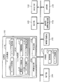
図1に本実施形態の画像生成システム(ゲームシステム)の機能ブロック図の例を示す。なお本実施形態の画像生成システムは図1の構成要素(各部)の一部を省略した構成としてもよい。
1. Configuration FIG. 1 shows an example of a functional block diagram of an image generation system (game system) of the present embodiment. Note that the image generation system of the present embodiment may have a configuration in which some of the components (each unit) in FIG. 1 are omitted.
操作部160(ゲームコントローラ)は、プレーヤが操作データを入力するためのものであり、その機能は、方向キー、アナログスティック、ボタン、レバー、ステアリング、マイク、タッチパネル型ディスプレイ、或いは筺体などにより実現できる。 The operation unit 160 (game controller) is for a player to input operation data, and the function can be realized by a direction key, an analog stick, a button, a lever, a steering, a microphone, a touch panel display, or a housing. .
記憶部170は、処理部100や通信部196などのワーク領域となるもので、その機能はRAMなどにより実現できる。
The
情報記憶媒体180(コンピュータにより読み取り可能な媒体)は、プログラムやデータなどを格納するものであり、その機能は、光ディスク(CD、DVD)、光磁気ディスク(MO)、磁気ディスク、ハードディスク、磁気テープ、或いはメモリ(ROM)などにより実現できる。処理部100は、情報記憶媒体180に格納されるプログラム(データ)に基づいて本実施形態の種々の処理を行う。即ち情報記憶媒体180には、本実施形態の各部としてコンピュータを機能させるためのプログラム(各部の処理をコンピュータに実行させるためのプログラム)が記憶される。
The information storage medium 180 (computer-readable medium) stores programs, data, and the like, and functions as an optical disk (CD, DVD), magneto-optical disk (MO), magnetic disk, hard disk, and magnetic tape. Alternatively, it can be realized by a memory (ROM). The
表示部190は、本実施形態により生成された画像を出力するものであり、その機能は、CRT、LCD、タッチパネル型ディスプレイ、或いはHMD(ヘッドマウントディスプレイ)などにより実現できる。
The
音出力部192は、本実施形態により生成された音を出力するものであり、その機能は、スピーカ、或いはヘッドフォンなどにより実現できる。
The
携帯型情報記憶装置194は、プレーヤの個人データやゲームのセーブデータなどが記憶されるものであり、この携帯型情報記憶装置194としては、メモリカードや携帯型ゲーム装置などがある。通信部196は外部(例えばホスト装置や他の画像生成システム)との間で通信を行うための各種制御を行うものであり、その機能は、各種プロセッサ又は通信用ASICなどのハードウェアや、プログラムなどにより実現できる。
The portable
なお本実施形態の各部としてコンピュータを機能させるためのプログラム(データ)は、ホスト装置(サーバー)が有する情報記憶媒体からネットワーク及び通信部196を介して情報記憶媒体180(記憶部170)に配信してもよい。このようなホスト装置(サーバー)の情報記憶媒体の使用も本発明の範囲内に含めることができる。
Note that a program (data) for causing a computer to function as each unit of this embodiment is distributed from the information storage medium of the host device (server) to the information storage medium 180 (storage unit 170) via the network and
処理部100(プロセッサ)は、操作部160からの操作データやプログラムなどに基づいて、ゲーム処理、画像生成処理、或いは音生成処理などを行う。この処理部100は記憶部170をワーク領域として各種処理を行う。処理部100の機能は各種プロセッサ(CPU、DSP等)、ASIC(ゲートアレイ等)などのハードウェアや、プログラムなどにより実現できる。
The processing unit 100 (processor) performs game processing, image generation processing, sound generation processing, and the like based on operation data from the
処理部100は、ゲーム処理部110、画像生成部120、音生成部130を含む。ここでゲーム処理部110は、操作部160からの操作データやプログラムなどに基づいてゲーム処理を行う。このゲーム処理としては、ゲーム開始条件が満たされた場合にゲームを開始する処理、ゲームを進行させる処理、キャラクタやマップなどのオブジェクトを配置する処理、オブジェクトを表示する処理、ゲーム結果を演算する処理、或いはゲーム終了条件が満たされた場合にゲームを終了する処理などがある。
The
画像生成120は、処理部100で行われる種々の処理(ゲーム処理)の結果に基づいて描画処理を行い、これにより画像を生成し、表示部190に出力する。いわゆる3次元ゲーム画像を生成する場合には、まず、座標変換(ワールド座標変換、カメラ座標変換)、クリッピング処理、或いは透視変換等のジオメトリ処理が行われ、その処理結果に基づいて、描画データ(プリミティブ面の頂点の位置座標、テクスチャ座標、色データ、法線ベクトル或いはα値等)が作成される。そして、この描画データ(プリミティブ面データ)に基づいて、透視変換後(ジオメトリ処理後)のオブジェクト(1又は複数プリミティブ面)を描画領域172(フレームバッファ、ワークバッファ)に描画する。これにより、オブジェクト空間内において所与の視点(仮想カメラ)から見える画像が生成される。
The
音生成部130は、処理部100で行われる種々の処理の結果に基づいて音処理を行い、BGM、効果音、又は音声などのゲーム音を生成し、音出力部192に出力する。
The
ゲーム処理部110は、カーソル制御部112、オブジェクト制御部113、ヒット処理部114を含む。なおこれらの一部を省略する構成としてもよい。
The
ここでカーソル制御部112はカーソルの移動制御や表示制御を行う。より具体的にはカーソル制御部112は、操作部160により入力された操作データ(カーソル移動指示データ)に基づいて、第1の座標軸(例えばX軸)方向に沿ってカーソル(例えばミートカーソル)を移動させる。即ち操作部160からの操作データに基づいてカーソルの第1の座標軸での位置情報(例えばX座標などの座標成分)を逐次求める。
Here, the
オブジェクト制御部113はオブジェクト(ポリゴン、自由曲面又はサブディビジョンサーフェスなどのプリミティブ面で構成されるオブジェクト)についての種々の制御を行う。例えばキャラクタやボールなどのオブジェクトをオブジェクト空間に配置設定したり、オブジェクトの移動制御や表示制御を行う。即ち、ワールド座標系でのオブジェクト(モデルオブジェクト)の位置や回転角度(向き、方向と同義)を決定し、その位置にその回転角度でオブジェクトを配置する。また操作部160によりプレーヤが入力した操作データや、プログラム(移動・動作アルゴリズム)や、各種データ(モーションデータ)などに基づいて、オブジェクトをオブジェクト空間内で移動させたり、オブジェクトを動作(モーション、アニメーション)させる処理を行う。具体的には、オブジェクトの移動情報(位置、回転角度、速度、或いは加速度)や動作情報(各パーツオブジェクトの位置、或いは回転角度)を、1フレーム(1/60秒)毎に順次求めるシミュレーション処理を行う。なおフレームは、オブジェクトの移動・動作処理(シミュレーション処理)や画像生成処理を行う時間の単位である。
The
ヒット処理部114は、オブジェクト(例えばボール)についてヒット処理(ヒット判定処理、ヒット後のオブジェクトの移動制御等)を行う。具体的にはヒット処理部114は、ヒッティングポイント(バットのミートポイント)の第1の座標軸(X軸)方向での位置情報(X座標)を、カーソル(ミートカーソル)の第1の座標軸方向での位置情報(X座標)により設定する。一方、ヒッティングポイントの第2の座標軸(Y軸)方向での位置情報(Y座標などの座標成分やぶれ幅)については、自動調整により設定する。そして、このように第1、第2の座標軸方向での位置情報が設定されたヒッティングポイントと、オブジェクト制御部113により制御されるオブジェクトとのヒット処理(位置の一致判定処理等)を行う。なおヒッティングポイントの第1、第2の座標軸方向での位置情報は、第1、第2の座標成分(X座標、Y座標)であってもよいし、これらと等価な情報(例えばぶれ幅等)であってもよい。またヒッティングポイントは、仮想的なヒッティングポイントであり、表示してもよいし、表示しなくてもよい。
The hit processing unit 114 performs hit processing (hit determination processing, object movement control after hitting, etc.) for an object (for example, a ball). Specifically, the hit processing unit 114 uses the position information (X coordinate) of the hitting point (bat meet point) in the first coordinate axis (X axis) direction as the first coordinate axis direction of the cursor (meet cursor). Set by position information (X coordinate). On the other hand, the position information (coordinate components such as Y coordinate and blur width) of the hitting point in the second coordinate axis (Y axis) direction is set by automatic adjustment. Then, hit processing (position matching determination processing, etc.) is performed between the hitting point in which the position information in the first and second coordinate axis directions is set in this way and the object controlled by the
そして本実施形態ではヒット処理部114が、オブジェクトの第1の座標軸方向での位置情報(X座標)により設定されるエリア(ミートエリア)に、カーソル(ミートカーソル、ヒッティングポイント)が位置した時間(フレーム数)のカウント処理を行う。そして得られたカウント時間(計時時間)に基づいて、ヒッティングポイントの第2の座標軸方向での位置情報(座標成分、ぶれ幅)を自動調整(自動補正)する。この場合の自動調整は、例えば、テーブル記憶部174に記憶されるテーブルデータに基づいて行う。なお上述したエリアは、例えばオブジェクト(着弾ポイント)の第1の座標軸方向での位置情報を中心として所与の幅を有するエリアである。またカウント時間は、例えばカーソル又はカーソルの代表点が上記エリアに重なっていた時間をカウントすることで得ることができる。
In this embodiment, the hit processing unit 114 is the time when the cursor (meet cursor, hitting point) is located in the area (meet area) set by the position information (X coordinate) of the object in the first coordinate axis direction. (Frame number) is counted. Then, based on the obtained count time (time keeping time), the position information (coordinate component, blur width) of the hitting point in the second coordinate axis direction is automatically adjusted (automatically corrected). The automatic adjustment in this case is performed based on table data stored in the
ヒット処理部114は、着弾ポイント演算部115、カウント処理部116、自動調整部117、ヒッティング情報設定部118を含む。なおこれらの一部を省略する構成としてもよい。
The hit processing unit 114 includes a landing
ここで着弾ポイント演算部115は、第1、第2の座標軸を含む面(XY平面、スクリーンに平行な面)に対するオブジェクトの着弾ポイント(到達ポイント)を求める。カウント処理部116は、着弾ポイントの位置情報(第1の座標軸方向での位置情報)により設定されるエリア(ミートエリア)に、カーソルが位置した時間(エリアにカーソルが重なっていた時間)をカウントする。自動調整部117は、このカウント時間に基づいて、ヒッティングポイント(カーソル)の第2の座標軸方向での位置情報を自動調整する。具体的には、例えばテーブル記憶部174に記憶されるテーブルデータに基づいて、着弾ポイントに対するヒッティングポイントの第2の座標軸方向でのぶれ幅を設定する。ヒッティング情報設定部118は、設定されたぶれ幅に基づいて、ヒット後のオブジェクトのヒッティング情報(ヒッティング方向、ヒッティング速度、ヒッティング加速度、或いはヒッティング強さ)を設定する。ヒット後のオブジェクトの移動は、このヒッティング情報に基づいて制御される。
Here, the landing
なお、上述したエリアとして、第1の座標軸方向での幅が異なる複数の第1〜第Nのエリア(Nは2以上の整数)を設定してもよい。第1の座標軸がX軸である場合を例にとると、第1のエリアは、着弾ポイントのX座標(第1の座標軸での座標成分)XPを中心とした幅W1のエリアであり、第2のエリアは、XPを中心とした幅W2(>W1)のエリアであり、・・・・・第Nのエリアは、XPを中心とした幅WN(>WN−1)のエリアである。そしてヒット処理部114は、これらの第1〜第Nのエリアの各々についてカーソルが位置した時間をカウントする。例えば第1のエリアにカーソルが位置した時間である第1のカウント時間、第2のエリアにカーソルが位置した時間である第2のカウント時間、・・・・・・第Nのエリアにカーソルが位置した時間である第Nのカウント時間を求める。そして得られた第1〜第Nのカウント時間に基づいて、ヒッティングポイントの第2の座標軸方向での位置情報(Y座標、ぶれ幅)を自動調整する。この場合、第1〜第Nのカウント時間のうち、より幅の狭い第1のエリアに対応する第1のカウント時間が長い場合には、着弾ポイントに対するヒッティングポイントのぶれ幅を例えば小さくする。一方、より幅の広い第Nのエリアに対応する第Nのカウント時間が長い場合には、着弾ポイントに対するヒッティングポイントのぶれ幅を例えば大きくする。 A plurality of first to Nth areas (N is an integer of 2 or more) having different widths in the first coordinate axis direction may be set as the above-described areas. Taking the case where the first coordinate axis is the X axis as an example, the first area is an area having a width W1 centered on the X coordinate (coordinate component on the first coordinate axis) XP of the landing point, The area 2 is an area having a width W2 (> W1) centered on XP, and the Nth area is an area having a width WN (> WN-1) centered on XP. The hit processing unit 114 counts the time when the cursor is positioned in each of the first to Nth areas. For example, the first count time, which is the time when the cursor is located in the first area, the second count time, which is the time when the cursor is located in the second area, ... the cursor is in the Nth area The Nth count time, which is the position time, is obtained. Based on the obtained first to Nth count times, the position information (Y coordinate, blur width) of the hitting point in the second coordinate axis direction is automatically adjusted. In this case, when the first count time corresponding to the narrower first area among the first to Nth count times is long, the fluctuation width of the hitting point with respect to the landing point is reduced, for example. On the other hand, when the Nth count time corresponding to the Nth area having a wider width is long, the fluctuation width of the hitting point with respect to the landing point is increased, for example.
また、オブジェクトが、キャラクタ(投手キャラクタ)によりリリース(投球)されて移動するオブジェクト(ボール)である場合には、ヒット処理部114(カウント処理部116)は、キャラクタがオブジェクトをリリースしたタイミング以降のタイミングから、カウント処理を開始するようにする。このようにすれば、例えば攻撃側(打者側)のプレーヤが狙っているコースを、守備側(投手側)のプレーヤに知られてしまう事態を防止でき、人間同士の対戦ゲームの面白みを向上できる。 In addition, when the object is an object (ball) that is released (throwed) by the character (pitcher character) and moves, the hit processing unit 114 (count processing unit 116) is after the timing when the character releases the object. The count process is started from the timing. In this way, for example, it is possible to prevent a situation in which a course targeted by an attacking side (batter side) player is known to a player on the defensive side (pitcher side), and to improve the interest of a battle game between humans. .
またヒット処理部114(自動調整部117)は、ヒッティングタイミング(ミートタイミング)において、エリアにカーソルが位置していた場合に、オブジェクトがヒットされたと判定して、ヒッティングポイントの第2の座標軸方向での位置情報を自動調整する。またエリアにカーソルが位置すると判断された場合(時間カウント処理が開始された場合)に、そのことを画像(ガイドマーカ、色、点滅)や音(実況中継の音声、効果音等)や振動でプレーヤに知らせるようにしてもよい。 The hit processing unit 114 (automatic adjustment unit 117) determines that the object has been hit when the cursor is positioned in the area at the hitting timing (meet timing), and the second coordinate axis of the hitting point. Automatically adjust the position information in the direction. Also, if it is determined that the cursor is positioned in the area (when the time counting process is started), this is indicated by an image (guide marker, color, blinking), sound (live broadcast sound, sound effect, etc.) or vibration. You may make it notify a player.
なお振動で知らせる場合には、そのカーソルを操作しているプレーヤの操作部160(ゲームコントローラ)の振動機構を用いて、その操作部を振動させることで、プレーヤに知らせればよい。具体的には、エリアにカーソルが位置すると判断された場合には、ヒット処理部114(処理部100)が操作部160に対して振動イネーブル信号を出力する。そして、この振動イネーブル信号を受けた操作部160が、内蔵する公知の振動機構を用いて操作部160を振動させる。なお、エリアにカーソルが位置することを、操作部160以外の部材を振動させてプレーヤに知らせてもよい。
In the case of notifying by vibration, the player may be notified by vibrating the operation unit using the vibration mechanism of the operation unit 160 (game controller) of the player who is operating the cursor. Specifically, when it is determined that the cursor is positioned in the area, the hit processing unit 114 (processing unit 100) outputs a vibration enable signal to the
なお、本実施形態の画像生成システムは、1人のプレーヤのみがプレイできるシングルプレーヤモード専用のシステムにしてもよいし、複数のプレーヤがプレイできるマルチプレーヤモードも備えるシステムにしてもよい。また複数のプレーヤがプレイする場合に、これらの複数のプレーヤに提供するゲーム画像やゲーム音を、1つの端末を用いて生成してもよいし、ネットワーク(伝送ライン、通信回線)などで接続された複数の端末(ゲーム機、携帯電話)を用いて分散処理により生成してもよい。 Note that the image generation system of the present embodiment may be a system dedicated to the single player mode in which only one player can play, or may be a system having a multiplayer mode in which a plurality of players can play. Further, when a plurality of players play, game images and game sounds to be provided to the plurality of players may be generated using one terminal, or connected via a network (transmission line, communication line) or the like. Alternatively, it may be generated by distributed processing using a plurality of terminals (game machine, mobile phone).
2.本実施形態の手法
次に本実施形態の手法について図面を用いて詳細に説明する。なお以下では本実施形態を、球技系ゲームの1つである野球ゲームに適用した場合について説明するが、本実施形態はこれに限定されない。例えば、バレーボールゲーム(スパイク)やテニスゲーム(ストローク)やサッカーゲーム(ヘッディング)などの他の球技系ゲームにも本実施形態の手法は適用できる。また球技系ゲーム以外のゲーム(例えば格闘ゲーム、シューティングゲーム)に本実施形態の手法を適用することも可能である。
2. Next, the method of this embodiment will be described in detail with reference to the drawings. In addition, although the case where this embodiment is applied to the baseball game which is one of the ball game system games is demonstrated below, this embodiment is not limited to this. For example, the method of this embodiment can be applied to other ball games such as a volleyball game (spike), a tennis game (stroke), and a soccer game (heading). Also, the method of the present embodiment can be applied to a game other than a ball game system game (for example, a fighting game or a shooting game).
2.1 カウント時間に基づく自動調整
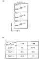
図2(A)〜図3に本実施形態により生成されるゲーム画像の例を示す。図2(A)において、守備側のプレーヤ(人間プレーヤ又はコンピュータプレーヤ)は、投手キャラクタCH1を操作し、球種や投球目標ポイント(着弾ポイント)や球速を設定し、投手キャラクタCH1にボールBL(広義にはオブジェクト)を投げさせる。
2.1 Automatic Adjustment Based on Count Time FIGS. 2A to 3 show examples of game images generated by the present embodiment. In FIG. 2A, the defensive player (human player or computer player) operates the pitcher character CH1 to set the ball type, the target pitch point (landing point) and the ball speed, and the ball BL ( In a broad sense, throw an object).
具体的には守備側のプレーヤ(第1のプレーヤ)は、図4の操作部(ゲームコントローラ)の方向キー10やアナログスティック20を操作して、球種(ストレート、カーブ、シュート、スライダー、フォーク等)を決める。なおこの図4の操作部は、図示しない公知の振動機構を有している。
Specifically, the defensive player (first player) operates the direction key 10 or the
次にストライクゾーンやボールゾーンとなるエリアの任意の位置を、方向キー10やアナログスティック20により指定して、投球目標ポイント(着弾ポイント)を設定する。そして図2(A)のゲージGGを見ながら、投球用のボタン30を押すことで、投手キャラクタCH1が投球モーションを開始してボールBLを投球(リリース)する。なおゲージGGが示す値が最大値になったところでボタン30を押すと、球速が最大になる。またボールBLの着弾(到達)ポイントには着弾マーカSMKが表示される。なお着弾マーカSMKは、現実の着弾ポイントを示すマーカであってもよいし、予測着弾ポイントを示すマーカであってもよい。予測着弾ポイントを示すマーカは、図2(A)の着弾マーカSMKよりも広い面積を有するマーカになる。また、ボールが打者キャラクタの近くに来るまでは、予測着弾ポイントを示す着弾マーカを表示し、ボールが打者キャラクタの近くに来たタイミングで、現実の着弾ポイントを示す着弾マーカを表示するようにしてもよい。なお着弾マーカSMK(予測着弾マーカ)は常に表示するようにしてもよいし、非表示にしてもよい。また着弾マーカSMKの表示のオン・オフを、プレーヤのゲーム設定により切り替えるようにしてもよい。またカーソルCSは仮想的な表示されないカーソルであってもよい。またカーソルの表示のオン・オフを、プレーヤのゲーム設定により切り替えるようにしてもよい。
Next, an arbitrary position in an area to be a strike zone or a ball zone is designated by the direction key 10 or the
攻撃側のプレーヤ(人間プレーヤ又はコンピュータプレーヤ)は、打者キャラクタCH2を操作し、投手キャラクタCH1が投球するボールBLを打つ。具体的には攻撃側のプレーヤ(第2のプレーヤ)は、図4の操作部の方向キー10やアナログスティック20を操作して、ミートカーソルCS(広義にはカーソル)を移動させる。この時、ミートカーソルCSの移動に追従するように打者キャラクタCH2も移動する。またミートカーソルCSは、攻撃側のプレーヤの操作により、X軸(広義には第1の座標軸)方向に沿って左右に移動する。例えば図4の方向キー10で左方向を指示したり、アナログスティック20を左方向に倒すと、ミートカーソルCSや打者キャラクタCH2は左方向に移動する。一方、方向キー10で右方向を指示したり、アナログスティック20を右方向に倒すと、ミートカーソルCSや打者キャラクタCH2は右方向に移動する。
The attacking player (human player or computer player) operates the batter character CH2 and hits the ball BL thrown by the pitcher character CH1. Specifically, the attacking player (second player) moves the meet cursor CS (cursor in a broad sense) by operating the direction key 10 or the
図2(B)に示すように攻撃側のプレーヤは、ミートカーソルCSのX座標が着弾マーカSMK(予測着弾マーカ)のX座標に一致するように、ミートカーソルCSを移動させる。そして図4のボタン30又は32を押して、打者キャラクタCH2にバットを振らせ、ボールBLのヒッティングを行う。なおボタン30を押すと、バットを強く振るパワー打撃が行われ、ボタン32を押すと、バットをコンパクトに振るミート打撃が行われる。
As shown in FIG. 2B, the attacking player moves the meet cursor CS so that the X coordinate of the meet cursor CS matches the X coordinate of the impact marker SMK (predicted impact marker). Then, the
ヒッティングのタイミング(バットがボールに当たるタイミング、スイングタイミング、ボタンを押したタイミング)において、ミートカーソルCSのX座標と、着弾マーカSMK(着弾ポイント)のX座標とが、所与のエリア内においてほぼ一致していると、ボールBLがヒットされたと判定される。そして図3に示すように、ボールBLがヒッティング方向に飛ぶ。 At the timing of hitting (timing at which the bat hits the ball, swing timing, timing at which the button is pressed), the X coordinate of the meet cursor CS and the X coordinate of the landing marker SMK (landing point) are approximately within a given area. If they match, it is determined that the ball BL has been hit. Then, as shown in FIG. 3, the ball BL flies in the hitting direction.
そして本実施形態では、バットのヒッティングポイント(ミートポイント)のX座標(広義には第1の座標軸方向での位置情報)については、ミートカーソルCSのX座標により設定される。一方、ヒッティングポイントのY座標(広義には第2の座標軸方向での位置情報)については、コンピュータによる自動調整により設定される。具体的には、ボールBL(オブジェクト)のX座標により設定されるエリアに、ミートカーソルCSが位置した時間(BLとCSのX座標が所定のエリア内で一致した時間、ミートカーソル位置がエリアに一致した時間)をカウントする。そして得られたカウント時間に基づいて、ヒッティングポイント(ミートカーソルCS)のY座標が自動調整される。このようにすれば、攻撃側のプレーヤは、ヒッティングポイントのX座標が着弾マーカSMKに一致するように操作するだけで済み、ヒッティングポイントのY座標については考慮する必要が無くなる。従って、初級者プレーヤなどに最適な操作インターフェース環境を提供できる。また本実施形態によれば、ヒッティングポイント(ミートカーソルCS)のX座標と着弾マーカSMKのX座標が一致していた時間が長いほど、自動調整のぶれ幅を小さくすることが可能になる。これにより、プレーヤのゲーム操作技量も、ある程度、ゲーム結果に反映させることが可能になり、好適な操作インターフェース環境を実現できる。 In the present embodiment, the X coordinate (position information in the first coordinate axis direction in a broad sense) of the hitting point (meet point) of the bat is set by the X coordinate of the meet cursor CS. On the other hand, the Y coordinate of the hitting point (position information in the second coordinate axis direction in a broad sense) is set by automatic adjustment by a computer. Specifically, the time when the meet cursor CS is located in the area set by the X coordinate of the ball BL (object) (the time when the X coordinate of BL and CS coincides within a predetermined area, the position of the meet cursor in the area) Counts the matching time). Based on the obtained count time, the Y coordinate of the hitting point (meet cursor CS) is automatically adjusted. In this way, the attacking player only needs to operate so that the X coordinate of the hitting point matches the landing marker SMK, and there is no need to consider the Y coordinate of the hitting point. Therefore, it is possible to provide an optimum operation interface environment for beginner players and the like. Further, according to the present embodiment, the longer the time during which the X coordinate of the hitting point (meet cursor CS) and the X coordinate of the landing marker SMK coincide, the smaller the blur width of the automatic adjustment can be made. Thereby, the game operation skill of the player can be reflected to some extent in the game result, and a suitable operation interface environment can be realized.
なお図2(B)では、ヒッティングポイントのX座標と着弾マーカSMKのX座標が一致していることを(ミートエリアにミートカーソルが位置することを)、ガイドマーカGD(画像)を用いてプレーヤに知らせている。例えば図2(B)では「ロックオン」と書かれたガイドマーカGDが表示されているが、これ以外の用語が書かれたガイドマーカGDを表示してもよい。或いは、ヒッティングポイントのX座標と着弾マーカSMKのX座標が一致した場合(ミートエリアにミートカーソルが位置した場合)に、例えばミートカーソルCSや着弾マーカSMKの色を変更したり、CSやSMKの点滅表示を行うことで、プレーヤに知らせるようにしてもよい。或いは、ヒッティングポイントのX座標と着弾マーカSMKのX座標が一致していることを、例えば音などの実況中継音声により、プレーヤに知らせてもよい。或いは、ヒッティングポイントのX座標と着弾マーカSMKのX座標が一致していることを、操作部を振動させることなどでプレーヤに知らせてもよい。 In FIG. 2B, the X coordinate of the hitting point and the X coordinate of the landing marker SMK are coincident (that the meet cursor is positioned in the meet area), and the guide marker GD (image) is used. The player is informed. For example, in FIG. 2B, a guide marker GD written as “lock on” is displayed, but a guide marker GD written in terms other than this may be displayed. Alternatively, when the X coordinate of the hitting point matches the X coordinate of the landing marker SMK (when the meet cursor is positioned in the meet area), for example, the color of the meet cursor CS or the landing marker SMK is changed, or the CS or SMK The player may be notified by flashing. Alternatively, the player may be informed of the X coordinate of the hitting point and the X coordinate of the landing marker SMK by, for example, a live broadcast voice such as a sound. Alternatively, the player may be informed that the X coordinate of the hitting point matches the X coordinate of the landing marker SMK by vibrating the operation unit.
またプレーヤのゲームモード設定(難易度設定等)に応じて、図2(A)〜図3で説明した簡易操作バッティングと、ヒッティングポイントのX、Y座標の両方をミートカーソルで設定する通常操作バッティングとを切り替えるようにしてもよい。 Further, in accordance with the game mode setting (difficulty level setting, etc.) of the player, the normal operation for setting both the simple operation batting described in FIGS. 2A to 3 and the X and Y coordinates of the hitting point with a meet cursor. You may make it switch between batting.
2.2 自動調整の詳細
次に本実施形態の自動調整手法の詳細について説明する。
2.2 Details of Automatic Adjustment Next, details of the automatic adjustment method of the present embodiment will be described.
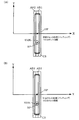
図5(A)(B)に示すように本実施形態では、着弾ポイントSPのX座標XPに基づいて、ミートエリアAR1、AR2(広義には第1〜第Nのエリア)が設定される。ここで着弾ポイントSP(到達ポイント)は、例えば、X軸、Y軸(第1、第2の座標軸)を含む面に対してボールBL(オブジェクト)が着弾(到達)するポイントである。具体的には、X軸、Y軸を含む面とボールBLの軌道との交点を着弾ポイントSPとすることができる。 As shown in FIGS. 5A and 5B, in the present embodiment, meet areas AR1 and AR2 (first to Nth areas in a broad sense) are set based on the X coordinate XP of the landing point SP. Here, the landing point SP (arrival point) is a point at which the ball BL (object) lands (arrives) on a plane including the X axis and the Y axis (first and second coordinate axes), for example. Specifically, the intersection point between the plane including the X axis and the Y axis and the trajectory of the ball BL can be set as the landing point SP.
またミートエリアAR1は、着弾ポイントSPのX座標XPを中心とした幅W1のエリアであり、このAR1はジャストミートエリアとして使用される。一方、ミートエリアAR2は座標XPを中心とした幅W2(>W1)のエリアであり、このAR2は通常ミートエリアとして使用される。なお図5(A)(B)では、ミートエリアAR1、AR2は、Y軸方向を長手方向とした長方形のエリアになっているが、これに限定されない。即ちミートエリアは、少なくとも着弾ポイントSPのX座標(第1の座標軸方向での位置情報)により設定されるエリアであればよく、その形状は問わない。また図5(A)(B)では、2個のミートエリアAR1、AR2を設定しているが、1個や3個以上のミートエリアを設定するようにしてもよい。 The meet area AR1 is an area having a width W1 centered on the X coordinate XP of the landing point SP, and this AR1 is used as a just meet area. On the other hand, the meet area AR2 is an area having a width W2 (> W1) centered on the coordinate XP, and this AR2 is normally used as a meet area. 5A and 5B, the meet areas AR1 and AR2 are rectangular areas whose longitudinal direction is the Y-axis direction, but the present invention is not limited to this. In other words, the meet area may be an area set by at least the X coordinate (position information in the first coordinate axis direction) of the landing point SP, and its shape is not limited. 5A and 5B, two meet areas AR1 and AR2 are set, but one or three or more meet areas may be set.
攻撃側のプレーヤが操作部の方向指示キー10やアナログスティック20を左右に操作すると、ヒッティングポイントHPの位置を示すミートカーソルCSもX軸方向に沿って左右に移動する。そして図6(A)に示すように、ミートエリアAR1、AR2にミートカーソルCS(CS又はCSの代表点)が位置すると、その位置した時間(AR1、AR2にCSが重なった時間)のカウント処理が開始する。そして図6(B)に示すように、カウント処理により得られたカウント時間(フレーム数)に基づいて、ヒッティングポイントHPのY座標(第2の座標軸方向での位置情報)が自動調整される。即ち着弾ポイントSP(着弾マーカSMK)のY座標に近づくように、ヒッティングポイントHPのY座標が自動調整される。この時、ミートカーソルCSの表示形態は、例えば、着弾ポイントSPにミートカーソルCSがロックオンしたことを示す表示形態に変更される。
When the attacking player operates the
そして本実施形態では、カウント処理により得られたカウント時間に基づいて、着弾ポイントSPに対するヒッティングポイントHPのY軸方向(第2の座標軸方向)でのぶれ幅(補正値)を設定している。そして設定されたぶれ幅に基づいて、ヒット後のボールBLのヒッティング情報(ヒッティング方向、ヒッティング速度、ヒッティング加速度、ヒッティング強さ)を設定している。例えば図7(A)に示すように、カウント時間が小さい場合には、着弾ポイントSPに対するヒッティングポイントHPのぶれ幅を大きくする。これにより、バッティング結果が凡打になる確率が高くなる。一方、図7(B)に示すように、カウント時間が大きい場合には、着弾ポイントSPに対するヒッティングポイントHPのぶれ幅を小さくする。これにより、バッティング結果がホームランやヒットになる確率が高くなる。 In the present embodiment, the blur width (correction value) in the Y-axis direction (second coordinate axis direction) of the hitting point HP with respect to the landing point SP is set based on the count time obtained by the count process. . Based on the set fluctuation width, hitting information (hitting direction, hitting speed, hitting acceleration, hitting strength) of the ball BL after the hit is set. For example, as shown in FIG. 7A, when the count time is small, the fluctuation width of the hitting point HP with respect to the landing point SP is increased. As a result, the probability that the batting result is an ordinary hit increases. On the other hand, as shown in FIG. 7B, when the count time is long, the fluctuation width of the hitting point HP with respect to the landing point SP is reduced. This increases the probability that the batting result will be a home run or a hit.
図8(A)(B)に、本実施形態の自動調整手法で使用されるテーブルデータの例を示す。図8(A)は、図4のボタン30を押してパワー打撃(パワースイング)を行った場合に参照されるテーブルデータの例であり、図8(B)はボタン32を押してミート打撃(コンパクトスイング)を行った場合に参照されるテーブルデータの例である。
8A and 8B show examples of table data used in the automatic adjustment method of this embodiment. FIG. 8A is an example of table data that is referred to when a power hit (power swing) is performed by pressing the
本実施形態では、ミートカーソルCSがジャストミートエリアAR1(第1のエリア)に例えば50パーセント(広義には所定のパーセント)以上重なっている時間TC1(第1のカウント時間)をカウントする。また、ミートカーソルCSが通常のミートエリアAR2(第2のエリア)に例えば50パーセント(広義には所定のパーセント)以上重なっている時間TC2(第2のカウント時間)をカウントする。またミートカーソルCSがAR1、AR2のどちらにも重なっていない時間TC3をカウントする。 In the present embodiment, a time TC1 (first count time) in which the meet cursor CS overlaps with the just meet area AR1 (first area) by, for example, 50 percent (predetermined percent in a broad sense) or more is counted. Further, a time TC2 (second count time) in which the meet cursor CS overlaps the normal meet area AR2 (second area) by, for example, 50 percent (predetermined percent in a broad sense) or more is counted. The time TC3 when the meet cursor CS does not overlap with either AR1 or AR2 is counted.
そしてTC1≧TC2>TC3であった場合には、ぶれ幅の小さいジャストミートであると判定する。またTC1<TC2≧TC3であった場合には、ぶれ幅が中ぐらいの通常のミートであると判定する。またTC1≦TC2<TC3であった場合には、ぶれ幅が大きい凡打であると判定する。なおエリアAR1の幅はミートカーソルCSの幅の例えば半分とすることができる。 If TC1 ≧ TC2> TC3, it is determined that the meat is a just meat with a small fluctuation width. Further, when TC1 <TC2 ≧ TC3, it is determined that the normal meat has a medium blur width. Further, when TC1 ≦ TC2 <TC3, it is determined that the stroke has a large blur width. The width of the area AR1 can be, for example, half the width of the meet cursor CS.
そして図8(A)に示すように、パワー打撃時においてジャストミートと判定されると、TC1/TALLに基づいて自動調整のぶれ幅が設定される。ここでTALLは、ボールがリリースされてから着弾(到達)するまでの時間(フレーム数)である。 Then, as shown in FIG. 8A, when it is determined to be just meat at the time of power hitting, an automatic adjustment blur width is set based on TC1 / TALL. Here, TALL is the time (number of frames) from when the ball is released until it reaches (arrives).
例えばTC1/TALLが1.0〜0.8である場合には、ぶれ幅は0.0に設定される。即ちこの場合には、着弾ポイントSPとヒッティングポイントHPとが一致し、ホームラン等の結果になる確率が極めて高くなる。またTC1/TALLが0.8〜0.5である場合には、ぶれ幅は0.2に設定される。即ち、着弾ポイントSPに対するヒッティングポイントHPのぶれ幅が、例えばボール幅の0.2倍(ボール0.2個分)になる。これにより、ホームラン等になる確率は低くなるが、クリーンヒットになる確率は高くなる。またTC1/TALLが0.5〜0.0である場合には、ぶれ幅は0.3に設定される。即ち着弾ポイントSPに対するヒッティングポイントHPのぶれ幅が、ボール幅の0.3倍になる。 For example, when TC1 / TALL is 1.0 to 0.8, the blur width is set to 0.0. In other words, in this case, the landing point SP and the hitting point HP coincide with each other, and the probability of a result such as a home run becomes extremely high. Further, when TC1 / TALL is 0.8 to 0.5, the blur width is set to 0.2. That is, the fluctuation width of the hitting point HP with respect to the landing point SP is, for example, 0.2 times the ball width (for 0.2 balls). This reduces the probability of becoming a home run or the like, but increases the probability of a clean hit. Further, when TC1 / TALL is 0.5 to 0.0, the blur width is set to 0.3. That is, the fluctuation width of the hitting point HP with respect to the landing point SP is 0.3 times the ball width.
通常ミート判定の場合は、ジャストミート判定の場合と同様に、TC2/TALLに基づいて自動調整のぶれ幅が設定される。また凡打判定の場合は、TC3/TALLに基づいて自動調整のぶれ幅が設定される。ミート打撃におけるジャストミート判定時、通常ミート判定時、凡打判定時でのぶれ幅についても、図8(B)のテーブルデータに基づいて設定される。 In the case of the normal meet determination, similarly to the case of the just meet determination, the blur width of the automatic adjustment is set based on TC2 / TALL. Further, in the case of the hitting determination, an automatic adjustment blur width is set based on TC3 / TALL. The blur width at the time of just-meet determination, normal meet determination, and approximate hit determination at the meet hit is also set based on the table data of FIG.
このように本実施形態では、X軸方向(第1の座標軸方向)での幅が異なる複数のエリアAR1、AR2(第1〜第Nのエリア)が設定される。そしてエリアAR1、AR2の各々についてミートカーソルCSが位置した時間をカウントする。そして、得られたカウント時間TC1やTC2(第1〜第Nのカウント時間)に基づいて、ヒッティングポイントHPのY座標(ぶれ幅)が自動調整される。 As described above, in the present embodiment, a plurality of areas AR1 and AR2 (first to Nth areas) having different widths in the X-axis direction (first coordinate axis direction) are set. Then, the time when the meet cursor CS is located for each of the areas AR1 and AR2 is counted. Then, based on the obtained count times TC1 and TC2 (first to Nth count times), the Y coordinate (blur width) of the hitting point HP is automatically adjusted.
また本実施形態では、着弾ポイントSPのY座標(第2の座標軸方向での位置情報)に基づいて、着弾ポイントSPに対するヒッティングポイントHPのぶれ方向を設定している。例えば図9(A)ではストライクゾーンが、上段ゾーンと中段ゾーンと下段ゾーン(第1〜第Kのゾーン)に分けられている。 In the present embodiment, the blur direction of the hitting point HP with respect to the landing point SP is set based on the Y coordinate of the landing point SP (position information in the second coordinate axis direction). For example, in FIG. 9A, the strike zone is divided into an upper zone, a middle zone, and a lower zone (first to Kth zones).
そして図9(B)に示すように、着弾ポイントSPがストライクゾーンの上段ゾーンの位置する場合(SPのY座標が大きい場合)には、着弾ポイントSPに対してヒッティングポイントHPが下方向(第2の座標軸に沿った第1の方向)にぶれるようにする。即ち、ぶれ方向は下方向になり、ヒッティングポイントHPのY座標の自動調整時に、図7(A)(B)の場合とは逆の方向にヒッティングポイントHPがぶれるようにする。このようにすれば、バットがボールの下半分にヒットするようになり、フライになる確率が高くなる。従って、高めのボールを打つとフライになるという現実世界の事象に近いシミュレーション表現を実現できる。 As shown in FIG. 9B, when the landing point SP is located in the upper zone of the strike zone (when the Y coordinate of the SP is large), the hitting point HP is downward (with respect to the landing point SP). The first direction along the second coordinate axis). That is, the blur direction is the downward direction, and the hitting point HP is shifted in the direction opposite to the case of FIGS. 7A and 7B when automatically adjusting the Y coordinate of the hitting point HP. In this way, the bat hits the lower half of the ball, and the probability of becoming a fly increases. Therefore, it is possible to realize a simulation expression close to a real-world event in which a high ball hits a fly.
また着弾ポイントSPが下段ゾーンの位置する場合(SPのY座標が小さい場合)には、着弾ポイントSPに対してヒッティングポイントHPが上方向(第2の座標軸に沿った第2方向)にぶれるようにする。即ち、ぶれ方向は上方向になり、ヒッティングポイントHPのY座標の自動調整時に、図7(A)(B)の場合と同じ方向にヒッティングポイントHPがぶれるようにする。このようにすれば、バットがボールの上半分にヒットするようになり、ゴロになる確率が高くなる。従って、低めのボールを打つとゴロになるという現実世界の事象に近いシミュレーション表現を実現できる。なお図9(A)では、ストライクゾーンを複数のゾーンに分けて、ぶれ方向を設定しているが、着弾ポイントSPのY座標を直接に用いて、ぶれ方向を設定するようにしてもよい。 Further, when the landing point SP is located in the lower zone (when the Y coordinate of the SP is small), the hitting point HP deviates upward (second direction along the second coordinate axis) with respect to the landing point SP. Like that. That is, the blur direction is upward, and the hitting point HP is shifted in the same direction as in FIGS. 7A and 7B when automatically adjusting the Y coordinate of the hitting point HP. In this way, the bat hits the upper half of the ball, and the probability of becoming a goro increases. Therefore, it is possible to realize a simulation expression close to a real-world event in which a low ball hits a ball. In FIG. 9A, the strike direction is set by dividing the strike zone into a plurality of zones, but the shake direction may be set by directly using the Y coordinate of the landing point SP.
また本実施形態では、エリアAR1、AR2にミートカーソルCSが位置した時間のカウント処理を、図2(A)に示すように、投手キャラクタCH1がボールBL(広義にはオブジェクト)をリリースしたタイミング以降のタイミングから開始している。即ち、このタイミングよりも前のタイミングから時間カウント処理を開始すると、守備側のプレーヤが、ミートカーソルCSの位置を見て、投球目標ポイント(着弾ポイント)を変えるという事態が生じてしまい、守備側のプレーヤが不当に有利になってしまうからである。またボールBLがリリースされてから着弾(到達)するまでの期間は比較的短いため、この期間において時間カウント処理を行うようにすれば、緊張感やスピード感に溢れるゲームを実現できる。 Further, in the present embodiment, the counting process of the time when the meet cursor CS is located in the areas AR1 and AR2 is performed after the timing when the pitcher character CH1 releases the ball BL (object in a broad sense) as shown in FIG. It starts from the timing. That is, when the time counting process is started from a timing before this timing, a situation occurs in which the defensive player changes the throwing target point (landing point) by looking at the position of the meet cursor CS. This is because the player becomes unfairly advantageous. Also, since the period from when the ball BL is released until it reaches (arrives) is relatively short, if the time counting process is performed during this period, a game full of tension and speed can be realized.
また本実施形態では、ヒッティングタイミング(スイング時)においてミートエリアAR1、AR2にミートカーソルCSが位置していたことを条件に、ボールがヒットされたと判定し、ヒッティングポイントHPの自動調整を行うようにしている。 In the present embodiment, it is determined that the ball has been hit on the condition that the meet cursor CS is positioned in the meet areas AR1 and AR2 at the hitting timing (during swing), and the hitting point HP is automatically adjusted. I am doing so.
例えば図10(A)では、ヒッティングタイミングにおいて、ミートエリアAR1、AR2にミートカーソルCSが位置している(AR1、AR2にCSが重なっている)。従って、この場合には、ボールがヒットされたと判定し、ヒッティングポイントHPのY座標の自動調整を行う。これにより打撃結果は、例えばホームランやヒットや凡打になる。 For example, in FIG. 10A, the meet cursor CS is positioned in the meet areas AR1 and AR2 at the hitting timing (CS overlaps AR1 and AR2). Therefore, in this case, it is determined that the ball has been hit, and the Y coordinate of the hitting point HP is automatically adjusted. As a result, the hitting result becomes, for example, a home run, a hit or a general hit.
一方、図10(B)では、ヒッティングタイミングにおいて、ミートエリアAR1、AR2にミートカーソルCSが位置していない(AR1、AR2にCSが重なっていない)。従って、この場合には、ボールがヒットされなかったと判定し、ヒッティングポイントHPのY座標の自動調整を行わないようにする。これにより打撃結果は、例えば空振りになる。 On the other hand, in FIG. 10B, the meet cursor CS is not located in the meet areas AR1 and AR2 at the hitting timing (the CS does not overlap AR1 and AR2). Therefore, in this case, it is determined that the ball has not been hit, and automatic adjustment of the Y coordinate of the hitting point HP is not performed. As a result, the hitting result is, for example, an empty swing.
このようにすれば、ミートカーソルCSのX座標を着弾ポイントSPのX座標に一致させたとしても、図4の打撃用のボタン30又は32を押すタイミングが悪いと、打撃結果も悪い結果になる。従って、ボタンを押すタイミングの技量の良し悪しに応じてゲーム結果が異なるようになり、ゲームの面白みや緊張感を増すことができる。
In this way, even if the X coordinate of the meet cursor CS is matched with the X coordinate of the landing point SP, if the timing of pressing the
更に本実施形態では、今回のヒット処理においてカウントされたカウント時間と、前回のヒット処理においてカウントされたカウント時間に基づいて、ヒッティングポイントのY座標の自動調整を行うようにすることもできる。 Further, in the present embodiment, the Y coordinate of the hitting point can be automatically adjusted based on the count time counted in the current hit process and the count time counted in the previous hit process.
例えば図11(A)では、前回のヒット処理(バッティング)において、ミートエリアAR1、AR2にミートカーソルCSが位置していた時間がカウントされている。一方、図11(B)では、今回のヒット処理(バッティング)において、ミートエリアAR1、AR2にミートカーソルCSが位置していた時間がカウントされている。そして自動調整は、図11(A)の前回のカウント時間と図11(B)の今回のカウント時間に基づいて行われる。即ち前回のカウント時間を今回のカウント時間に持ち越すことができる。 For example, in FIG. 11A, the time during which the meet cursor CS is located in the meet areas AR1 and AR2 in the previous hit process (batting) is counted. On the other hand, in FIG. 11B, the time during which the meet cursor CS is located in the meet areas AR1 and AR2 in the current hit process (batting) is counted. The automatic adjustment is performed based on the previous count time in FIG. 11A and the current count time in FIG. That is, the previous count time can be carried over to the current count time.
例えば野球においては、バッターが、外角コースなどの所定のコースに山を張って待つことがある。図11(A)(B)の手法によれば、攻撃側のプレーヤが所定のコースに山を張ってミートカーソルCSの位置を設定している場合には、その攻撃側のプレーヤの打撃結果を有利に設定することが可能になる。例えば前回のバッティングにおいて、外角コースを狙うようにミートカーソルCSを左よりに位置させており、今回のバッティングにおいても、外角コースを狙うようにミートカーソルを左よりに位置させていた場合には、自動調整におけるぶれ幅が小さくなる。これにより、ホームランやヒットになる確率が高まり、コースに山を張っているプレーヤが有利になる。この結果、プレーヤの仮想現実感を向上できる。 For example, in baseball, a batter may wait for a predetermined course such as an outside corner course. 11A and 11B, when the attacking player sets a position of the meat cursor CS by placing a mountain on a predetermined course, the attacking result of the attacking player is displayed. It becomes possible to set advantageously. For example, in the previous batting, if the meat cursor CS is positioned from the left so as to aim at the outer corner course, and in this batting, if the meat cursor is positioned from the left so as to aim at the outer corner course, The blur width in automatic adjustment is reduced. This increases the probability of a home run or a hit, which is advantageous for players who have a mountain on the course. As a result, the virtual reality of the player can be improved.
なお図11(A)(B)では、前回のヒット処理(バッティング)において得られたカウント時間を保存して、今回のヒット処理での自動調整に用いているが、これに加えて前々回やそれ以前のヒット処理において得られたカウント時間を保存して、今回のヒット処理での自動調整に用いているようにしてもよい。 In FIGS. 11A and 11B, the count time obtained in the previous hit process (batting) is stored and used for automatic adjustment in the current hit process. The count time obtained in the previous hit process may be stored and used for automatic adjustment in the current hit process.
3.本実施形態の処理
次に本実施形態の詳細な処理例について図12のフローチャートを用いて説明する。
3. Processing of this Embodiment Next, a detailed processing example of this embodiment will be described with reference to the flowchart of FIG.
まず着弾ポイントの位置を求める(ステップS1)。この着弾ポイントの位置は、例えば、守備側プレーヤが設定した球種、投球目標ポイント、球速などに基づいてコンピュータが求めることができる。 First, the position of the landing point is obtained (step S1). The position of the landing point can be obtained by the computer based on, for example, the ball type set by the defensive player, the throwing target point, the ball speed, and the like.
次に、図5(A)(B)で説明したように、着弾ポイントの位置(X座標)に基づいて、ミートエリアを設定する(ステップS2)。また攻撃側プレーヤの操作によりX軸方向に沿って移動するミートカーソルの位置(X座標)を求める(ステップS3)。 Next, as described in FIGS. 5A and 5B, a meet area is set based on the position (X coordinate) of the landing point (step S2). Further, the position (X coordinate) of the meet cursor that moves along the X-axis direction by the operation of the attacking player is obtained (step S3).
次に、図6(A)で説明したように、ミートエリアにミートカーソルが位置した時間(ミートエリアにミートカーソルが重なっていた時間)をカウントする(ステップS4)。複数のミートエリアがある場合には、このカウント処理は、各ミートエリア毎に行うことができる。 Next, as described with reference to FIG. 6A, the time when the meet cursor is located in the meet area (the time when the meet cursor overlaps with the meet area) is counted (step S4). When there are a plurality of meet areas, this counting process can be performed for each meet area.
次に、攻撃側プレーヤが図4のボタン30又は32を押して、打者キャラクタにスイングを行わせたか否かを判断する(ステップS5)。そしてスイングが行われなかった場合には、見逃しと判定する(ステップS6)。一方、スイングが行われた場合には、図10(A)(B)で説明したように、ヒッティングタイミング(スイング時)において、ミートエリアにミートカーソルが位置していたか否かを判断する(ステップS7)。そして、位置していなかった場合には、空振りと判定する(ステップS8)。一方、位置していた場合には、ステップS4で得られたカウント時間に基づいて、図8(A)(B)や図9(B)に示すようなテーブルデータを参照し、ヒッティングポイント(ミートカーソル)のぶれ幅やぶれ方向を自動調整する(ステップS9)。そして、得られたぶれ幅やぶれ方向に基づいて、ボールのヒッティング情報を設定し、ボールをヒット方向に飛ばす処理を行う(ステップS10)。そして、このようなボールやカーソルの画像を含むフレーム画像の生成や、実況中継音声などのゲーム音の生成処理を行う(ステップS11)。
Next, it is determined whether or not the attacking player has pressed the
4.ハードウェア構成
図13に本実施形態を実現できるハードウェア構成の例を示す。メインプロセッサ900は、CD982(情報記憶媒体)に格納されたプログラム、通信インターフェース990を介してダウンロードされたプログラム、或いはROM950に格納されたプログラムなどに基づき動作し、ゲーム処理、画像処理、音処理などを実行する。コプロセッサ902は、メインプロセッサ900の処理を補助するものであり、マトリクス演算(ベクトル演算)を高速に実行する。例えばオブジェクトを移動させたり動作(モーション)させる物理シミュレーションに、マトリクス演算処理が必要な場合には、メインプロセッサ900上で動作するプログラムが、その処理をコプロセッサ902に指示(依頼)する。
4). Hardware Configuration FIG. 13 shows an example of a hardware configuration that can realize this embodiment. The
ジオメトリプロセッサ904は、メインプロセッサ900上で動作するプログラムからの指示に基づいて、座標変換、透視変換、光源計算、曲面生成などのジオメトリ処理を行うものであり、マトリクス演算を高速に実行する。データ伸張プロセッサ906は、圧縮された画像データや音データのデコード処理を行ったり、メインプロセッサ900のデコード処理をアクセレートする。これにより、オープニング画面やゲーム画面において、MPEG方式等で圧縮された動画像を表示できる。
The
描画プロセッサ910は、ポリゴンや曲面などのプリミティブ面で構成されるオブジェクトの描画(レンダリング)処理を実行する。オブジェクトの描画の際には、メインプロセッサ900は、DMAコントローラ970を利用して、描画データを描画プロセッサ910に渡すと共に、必要であればテクスチャ記憶部924にテクスチャを転送する。すると描画プロセッサ910は、描画データやテクスチャに基づいて、Zバッファなどを利用した隠面消去を行いながら、オブジェクトをフレームバッファ922に描画する。また描画プロセッサ910は、αブレンディング(半透明処理)、デプスキューイング、ミップマッピング、フォグ処理、バイリニア・フィルタリング、トライリニア・フィルタリング、アンチエリアシング、シェーディング処理なども行う。1フレーム分の画像がフレームバッファ922に書き込まれるとその画像はディスプレイ912に表示される。
The drawing
サウンドプロセッサ930は、多チャンネルのADPCM音源などを内蔵し、BGM、効果音、音声などのゲーム音を生成し、スピーカ932を介して出力する。ゲームコントローラ942やメモリカード944からのデータはシリアルインターフェース940を介して入力される。
The
ROM950にはシステムプログラムなどが格納される。業務用ゲームシステムの場合にはROM950が情報記憶媒体として機能し、ROM950に各種プログラムが格納される。なおROM950の代わりにハードディスクを利用してもよい。RAM960は各種プロセッサの作業領域となる。DMAコントローラ970は、プロセッサ、メモリ間でのDMA転送を制御する。CDドライブ980は、プログラム、画像データ、或いは音データなどが格納されるCD982にアクセスする。通信インターフェース990はネットワーク(通信回線、高速シリアルバス)を介して外部との間でデータ転送を行う。
The
なお本実施形態の各部の処理は、その全てをハードウェアのみにより実現してもよいし、情報記憶媒体に格納されるプログラムや通信インターフェースを介して配信されるプログラムにより実現してもよい。或いは、ハードウェアとプログラムの両方により実現してもよい。 Note that the processing of each unit of the present embodiment may be realized entirely by hardware, or may be realized by a program stored in an information storage medium or a program distributed via a communication interface. Alternatively, it may be realized by both hardware and a program.
そして本実施形態の各部の処理をハードウェアとプログラムの両方により実現する場合には、情報記憶媒体には、ハードウェア(コンピュータ)を本実施形態の各部として機能させるためのプログラムが格納される。より具体的には、上記プログラムが、ハードウェアである各プロセッサ902、904、906、910、930に処理を指示すると共に、必要であればデータを渡す。そして、各プロセッサ902、904、906、910、930は、その指示と渡されたデータとに基づいて本発明の各部の処理を実現する。
When the processing of each part of this embodiment is realized by both hardware and a program, a program for causing the hardware (computer) to function as each part of this embodiment is stored in the information storage medium. More specifically, the program instructs the
なお本発明は、上記実施形態で説明したものに限らず、種々の変形実施が可能である。例えば、明細書又は図面中の記載において広義や同義な用語(オブジェクト、カーソル、第1の座標軸、第2の座標軸、第1の座標軸方向での位置情報、第2の座標軸方向での位置情報等)として引用された用語(ボール、ミートカーソル、X軸、Y軸、X座標、Y座標・ぶれ幅等)は、明細書又は図面中の他の記載においても広義や同義な用語に置き換えることができる。 The present invention is not limited to that described in the above embodiment, and various modifications can be made. For example, terms in the specification or drawings that have broad or synonymous terms (object, cursor, first coordinate axis, second coordinate axis, position information in the first coordinate axis direction, position information in the second coordinate axis direction, etc. ) (Ball, meat cursor, X-axis, Y-axis, X-coordinate, Y-coordinate / blur width, etc.) can be replaced with broad or synonymous terms in the description or other descriptions in the drawings. it can.
またヒッティングポイントの設定手法やぶれ幅の自動調整手法も、本実施形態で説明したものに限定されず、これらと均等な手法も本発明の範囲に含まれる。また本実施形態では第1の座標軸がX軸であり、第2の座標軸がY軸である場合について説明したが、第1、第2の座標軸は直交又は交差していれば十分であり、X軸、Y軸に限定されない。 Also, the hitting point setting method and the blur width automatic adjustment method are not limited to those described in the present embodiment, and techniques equivalent to these are also included in the scope of the present invention. In this embodiment, the first coordinate axis is the X axis and the second coordinate axis is the Y axis. However, it is sufficient that the first and second coordinate axes are orthogonal or intersecting, The axis is not limited to the Y axis.
また本発明は種々のゲームに適用できる。また本発明は、業務用ゲームシステム、家庭用ゲームシステム、多数のプレーヤが参加する大型アトラクションシステム、シミュレータ、マルチメディア端末、ゲーム画像を生成するシステムボード、携帯端末、携帯電話等の種々の画像生成システムに適用できる。 The present invention can be applied to various games. The present invention also provides various image generation such as a business game system, a home game system, a large attraction system in which a large number of players participate, a simulator, a multimedia terminal, a system board for generating a game image, a mobile terminal, a mobile phone, etc. Applicable to the system.
100 処理部、110 ゲーム処理部、112 カーソル制御部、
113 オブジェクト制御部、114 ヒット処理部、115 着弾ポイント演算部、
116 カウント処理部、117 自動調整部、118 ヒッティング情報設定部、
120 画像生成部、130 音生成部、160 操作部、170 記憶部、
172 描画領域、174 テーブル記憶部、180 情報記憶媒体、
190 表示部、192 音出力部、194 携帯型情報記憶装置、196 通信部
100 processing unit, 110 game processing unit, 112 cursor control unit,
113 Object control unit, 114 hit processing unit, 115 landing point calculation unit,
116 count processing unit, 117 automatic adjustment unit, 118 hitting information setting unit,
120 image generation unit, 130 sound generation unit, 160 operation unit, 170 storage unit,
172 drawing area, 174 table storage unit, 180 information storage medium,
190 display unit, 192 sound output unit, 194 portable information storage device, 196 communication unit
Claims (11)
操作部により入力された操作データに基づいて、第1の座標軸方向に沿ってカーソルを移動させる制御を行うカーソル制御部と、
オブジェクト空間においてオブジェクトを移動させる制御を行うオブジェクト制御部と、
前記カーソルの第1の座標軸方向での位置情報に基づいて、ヒッティングポイントの第1の座標軸方向での位置情報を設定し、前記オブジェクトの第1の座標軸方向での位置情報により設定されるエリアに前記カーソルが位置した時間のカウント処理を行って得られたカウント時間に基づいて、前記ヒッティングポイントの第2の座標軸方向での位置情報を設定し、前記ヒッティングポイントと前記オブジェクトとのヒット処理を行うヒット処理部と、
前記オブジェクト及び前記カーソルの画像を含む画像を生成する画像生成部として、
コンピュータを機能させることを特徴とするプログラム。 A program for generating an image,
A cursor control unit that performs control to move the cursor along the first coordinate axis direction based on operation data input by the operation unit;
An object control unit for controlling the movement of the object in the object space;
Based on the position information in the first coordinate axis direction of the cursor, the location information of a first coordinate axis direction of the hitting points and set, is set by the position information in the first coordinate axis direction of the object the cursor is on the basis of a count time obtained by performing the counting process of the time located in the area, the set the position information in the second coordinate axis direction of the hitting points, and the said hitting point object A hit processing unit that performs the hit processing of
As an image generation unit that generates an image including the image of the object and the cursor,
A program characterized by causing a computer to function.
前記ヒット処理部が、
第1、第2の座標軸を含む面に対する前記オブジェクトの着弾ポイントを求め、前記カウント時間に基づいて、前記着弾ポイントに対する前記ヒッティングポイントの第2の座標軸方向でのぶれ幅を設定し、設定されたぶれ幅に基づいて、ヒット後のオブジェクトのヒッティング情報を設定することを特徴とするプログラム。 In claim 1,
The hit processing unit
A landing point of the object with respect to a plane including the first and second coordinate axes is obtained, and a blur width in the second coordinate axis direction of the hitting point with respect to the landing point is set and set based on the count time. A program characterized in that hitting information of an object after a hit is set based on a shake width.
前記ヒット処理部が、
前記着弾ポイントの第2の座標軸方向での位置情報に基づいて、前記着弾ポイントに対する前記ヒッティングポイントのぶれ方向を設定することを特徴とするプログラム。 In claim 2,
The hit processing unit
A program for setting a blurring direction of the hitting point with respect to the landing point based on position information of the landing point in the second coordinate axis direction.
前記エリアとして、第1の座標軸方向での幅が異なる第1〜第Nのエリア(Nは2以上の整数)が設定され、
前記ヒット処理部が、
前記第1〜第Nのエリアの各々について前記カーソルが位置した時間をカウントし、得られた第1〜第Nのカウント時間に基づいて、前記ヒッティングポイントの第2の座標軸方向での位置情報を自動調整することを特徴とするプログラム。 In any one of Claims 1 thru | or 3,
As the area, first to Nth areas (N is an integer of 2 or more) having different widths in the first coordinate axis direction are set,
The hit processing unit
The time at which the cursor is positioned for each of the first to Nth areas is counted, and based on the obtained first to Nth count times, the position information of the hitting point in the second coordinate axis direction A program characterized by automatic adjustment.
前記オブジェクトが、キャラクタによりリリースされて移動するオブジェクトであり、
前記ヒット処理部が、
前記キャラクタが前記オブジェクトをリリースしたタイミング以降のタイミングから、前記エリアに前記カーソルが位置した時間のカウント処理を開始することを特徴とするプログラム。 In any one of Claims 1 thru | or 4,
The object is an object that is released and moved by the character;
The hit processing unit
A program for starting a counting process of a time when the cursor is positioned in the area from a timing after a timing when the character releases the object.
前記ヒット処理部が、
ヒッティングタイミングにおいて前記エリアに前記カーソルが位置していた場合に、オブジェクトがヒットされたと判定して、ヒッティングポイントの自動調整を行うことを特徴とするプログラム。 In any one of Claims 1 thru | or 5,
The hit processing unit
A program for automatically adjusting a hitting point by determining that an object has been hit when the cursor is positioned in the area at a hitting timing.
前記ヒット処理部が、
今回のヒット処理においてカウントされたカウント時間と、前回のヒット処理においてカウントされたカウント時間に基づいて、前記ヒッティングポイントの第2の座標軸方向での位置情報を自動調整することを特徴とするプログラム。 In any one of Claims 1 thru | or 6.
The hit processing unit
A program for automatically adjusting the position information of the hitting point in the second coordinate axis direction based on the count time counted in the current hit process and the count time counted in the previous hit process .
前記エリアに前記カーソルが位置することを画像、音又は振動でプレーヤに知らせることを特徴とするプログラム。 In any one of Claims 1 thru | or 7,
A program for notifying a player by an image, sound or vibration that the cursor is positioned in the area.
前記カーソルが野球ゲームにおけるミートカーソルであり、前記オブジェクトが野球ゲームにおけるボールであることを特徴とするプログラム。 In any one of Claims 1 thru | or 8.
A program characterized in that the cursor is a meet cursor in a baseball game and the object is a ball in a baseball game.
操作部により入力された操作データに基づいて、第1の座標軸方向に沿ってカーソルを移動させる制御を行うカーソル制御部と、
オブジェクト空間においてオブジェクトを移動させる制御を行うオブジェクト制御部と、
前記カーソルの第1の座標軸方向での位置情報に基づいて、ヒッティングポイントの第1の座標軸方向での位置情報を設定し、前記オブジェクトの第1の座標軸方向での位置情報により設定されるエリアに前記カーソルが位置した時間のカウント処理を行って得られたカウント時間に基づいて、前記ヒッティングポイントの第2の座標軸方向での位置情報を設定し、前記ヒッティングポイントと前記オブジェクトとのヒット処理を行うヒット処理部と、
前記オブジェクト及び前記カーソルの画像を含む画像を生成する画像生成部と、
を含むことを特徴とする画像生成システム。 An image generation system for generating an image,
A cursor control unit that performs control to move the cursor along the first coordinate axis direction based on operation data input by the operation unit;
An object control unit for controlling the movement of the object in the object space;
Based on the position information in the first coordinate axis direction of the cursor, the location information of a first coordinate axis direction of the hitting points and set, is set by the position information in the first coordinate axis direction of the object the cursor is on the basis of a count time obtained by performing the counting process of the time located in the area, the set the position information in the second coordinate axis direction of the hitting points, and the said hitting point object A hit processing unit that performs the hit processing of
An image generation unit that generates an image including an image of the object and the cursor ;
Image generation system characterized it to contain.
Priority Applications (1)
| Application Number | Priority Date | Filing Date | Title |
|---|---|---|---|
| JP2004014934A JP3686069B2 (en) | 2004-01-22 | 2004-01-22 | Program, information storage medium, and image generation system |
Applications Claiming Priority (1)
| Application Number | Priority Date | Filing Date | Title |
|---|---|---|---|
| JP2004014934A JP3686069B2 (en) | 2004-01-22 | 2004-01-22 | Program, information storage medium, and image generation system |
Publications (2)
| Publication Number | Publication Date |
|---|---|
| JP2005204946A JP2005204946A (en) | 2005-08-04 |
| JP3686069B2 true JP3686069B2 (en) | 2005-08-24 |
Family
ID=34900567
Family Applications (1)
| Application Number | Title | Priority Date | Filing Date |
|---|---|---|---|
| JP2004014934A Expired - Lifetime JP3686069B2 (en) | 2004-01-22 | 2004-01-22 | Program, information storage medium, and image generation system |
Country Status (1)
| Country | Link |
|---|---|
| JP (1) | JP3686069B2 (en) |
Cited By (2)
| Publication number | Priority date | Publication date | Assignee | Title |
|---|---|---|---|---|
| JP2007185359A (en) * | 2006-01-13 | 2007-07-26 | Namco Bandai Games Inc | Program, information storing medium, and image generation system |
| JP2015112354A (en) * | 2013-12-12 | 2015-06-22 | 株式会社コナミデジタルエンタテインメント | Game apparatus, game system, and program |
Families Citing this family (2)
| Publication number | Priority date | Publication date | Assignee | Title |
|---|---|---|---|---|
| JP5519115B2 (en) * | 2008-04-02 | 2014-06-11 | 株式会社バンダイナムコゲームス | Game information distribution system and program |
| CN113617030B (en) * | 2021-08-06 | 2023-08-22 | 腾讯科技(深圳)有限公司 | Virtual object control method, device, terminal and storage medium |
-
2004
- 2004-01-22 JP JP2004014934A patent/JP3686069B2/en not_active Expired - Lifetime
Cited By (2)
| Publication number | Priority date | Publication date | Assignee | Title |
|---|---|---|---|---|
| JP2007185359A (en) * | 2006-01-13 | 2007-07-26 | Namco Bandai Games Inc | Program, information storing medium, and image generation system |
| JP2015112354A (en) * | 2013-12-12 | 2015-06-22 | 株式会社コナミデジタルエンタテインメント | Game apparatus, game system, and program |
Also Published As
| Publication number | Publication date |
|---|---|
| JP2005204946A (en) | 2005-08-04 |
Similar Documents
| Publication | Publication Date | Title |
|---|---|---|
| US7084855B2 (en) | Image generation method, program, and information storage medium | |
| JP4883759B2 (en) | Program, information storage medium, and image generation system | |
| JP3239683B2 (en) | Image processing apparatus and image processing method | |
| JP3927821B2 (en) | PROGRAM, INFORMATION STORAGE MEDIUM, AND GAME DEVICE | |
| US20100245365A1 (en) | Image generation system, image generation method, and computer program product | |
| JP3747050B1 (en) | Program, information storage medium, and image generation system | |
| JP2006230578A (en) | Program, information storage medium and game apparatus | |
| US8827783B2 (en) | Game device, game control method and recording medium | |
| JP2003067779A (en) | Image generation system, program and information storage medium | |
| JP2001321562A (en) | Game system and information recording medium | |
| JP2009000383A (en) | Program, information recording medium and image generating system | |
| US8465353B2 (en) | Game device, control method for game device, and information storage medium | |
| JP2003047766A (en) | Game information, information storage medium and game device | |
| JP3686071B2 (en) | Program, information storage medium, and image generation system | |
| JP4662271B2 (en) | Program, information storage medium, and image generation system | |
| JP4806608B2 (en) | Program, information storage medium, and image generation system | |
| JP2005246071A (en) | Image forming system and information storage medium | |
| JP2006268511A (en) | Program, information storage medium and image generation system | |
| JP3686069B2 (en) | Program, information storage medium, and image generation system | |
| JP4508719B2 (en) | Program, information storage medium, and game system | |
| JP3786671B1 (en) | Program, information storage medium, and image generation system | |
| JP2003210837A (en) | Image-generating system, program, and information- storage medium | |
| JP2008067853A (en) | Program, information storage medium and image generation system | |
| JP4420729B2 (en) | Program, information storage medium, and image generation system | |
| JP2010233752A (en) | Program, information storage medium, and image generation system |
Legal Events
| Date | Code | Title | Description |
|---|---|---|---|
| TRDD | Decision of grant or rejection written | ||
| A01 | Written decision to grant a patent or to grant a registration (utility model) |
Free format text: JAPANESE INTERMEDIATE CODE: A01 Effective date: 20050517 |
|
| A61 | First payment of annual fees (during grant procedure) |
Free format text: JAPANESE INTERMEDIATE CODE: A61 Effective date: 20050601 |
|
| R150 | Certificate of patent or registration of utility model |
Ref document number: 3686069 Country of ref document: JP Free format text: JAPANESE INTERMEDIATE CODE: R150 Free format text: JAPANESE INTERMEDIATE CODE: R150 |
|
| S531 | Written request for registration of change of domicile |
Free format text: JAPANESE INTERMEDIATE CODE: R313531 |
|
| S533 | Written request for registration of change of name |
Free format text: JAPANESE INTERMEDIATE CODE: R313533 |
|
| R350 | Written notification of registration of transfer |
Free format text: JAPANESE INTERMEDIATE CODE: R350 |
|
| FPAY | Renewal fee payment (event date is renewal date of database) |
Free format text: PAYMENT UNTIL: 20080610 Year of fee payment: 3 |
|
| S531 | Written request for registration of change of domicile |
Free format text: JAPANESE INTERMEDIATE CODE: R313531 |
|
| FPAY | Renewal fee payment (event date is renewal date of database) |
Free format text: PAYMENT UNTIL: 20080610 Year of fee payment: 3 |
|
| R350 | Written notification of registration of transfer |
Free format text: JAPANESE INTERMEDIATE CODE: R350 |
|
| FPAY | Renewal fee payment (event date is renewal date of database) |
Free format text: PAYMENT UNTIL: 20090610 Year of fee payment: 4 |
|
| R250 | Receipt of annual fees |
Free format text: JAPANESE INTERMEDIATE CODE: R250 |
|
| FPAY | Renewal fee payment (event date is renewal date of database) |
Free format text: PAYMENT UNTIL: 20090610 Year of fee payment: 4 |
|
| FPAY | Renewal fee payment (event date is renewal date of database) |
Free format text: PAYMENT UNTIL: 20090610 Year of fee payment: 4 |
|
| FPAY | Renewal fee payment (event date is renewal date of database) |
Free format text: PAYMENT UNTIL: 20100610 Year of fee payment: 5 |
|
| R250 | Receipt of annual fees |
Free format text: JAPANESE INTERMEDIATE CODE: R250 |
|
| FPAY | Renewal fee payment (event date is renewal date of database) |
Free format text: PAYMENT UNTIL: 20100610 Year of fee payment: 5 |
|
| FPAY | Renewal fee payment (event date is renewal date of database) |
Free format text: PAYMENT UNTIL: 20110610 Year of fee payment: 6 |
|
| R250 | Receipt of annual fees |
Free format text: JAPANESE INTERMEDIATE CODE: R250 |
|
| FPAY | Renewal fee payment (event date is renewal date of database) |
Free format text: PAYMENT UNTIL: 20110610 Year of fee payment: 6 |
|
| FPAY | Renewal fee payment (event date is renewal date of database) |
Free format text: PAYMENT UNTIL: 20120610 Year of fee payment: 7 |
|
| R250 | Receipt of annual fees |
Free format text: JAPANESE INTERMEDIATE CODE: R250 |
|
| FPAY | Renewal fee payment (event date is renewal date of database) |
Free format text: PAYMENT UNTIL: 20120610 Year of fee payment: 7 |
|
| FPAY | Renewal fee payment (event date is renewal date of database) |
Free format text: PAYMENT UNTIL: 20130610 Year of fee payment: 8 |
|
| R250 | Receipt of annual fees |
Free format text: JAPANESE INTERMEDIATE CODE: R250 |
|
| FPAY | Renewal fee payment (event date is renewal date of database) |
Free format text: PAYMENT UNTIL: 20130610 Year of fee payment: 8 |
|
| R250 | Receipt of annual fees |
Free format text: JAPANESE INTERMEDIATE CODE: R250 |
|
| R250 | Receipt of annual fees |
Free format text: JAPANESE INTERMEDIATE CODE: R250 |
|
| R250 | Receipt of annual fees |
Free format text: JAPANESE INTERMEDIATE CODE: R250 |
|
| S531 | Written request for registration of change of domicile |
Free format text: JAPANESE INTERMEDIATE CODE: R313531 |
|
| R360 | Written notification for declining of transfer of rights |
Free format text: JAPANESE INTERMEDIATE CODE: R360 |
|
| S533 | Written request for registration of change of name |
Free format text: JAPANESE INTERMEDIATE CODE: R313533 |
|
| R370 | Written measure of declining of transfer procedure |
Free format text: JAPANESE INTERMEDIATE CODE: R370 |
|
| R250 | Receipt of annual fees |
Free format text: JAPANESE INTERMEDIATE CODE: R250 |
|
| R350 | Written notification of registration of transfer |
Free format text: JAPANESE INTERMEDIATE CODE: R350 |
|
| S531 | Written request for registration of change of domicile |
Free format text: JAPANESE INTERMEDIATE CODE: R313531 |
|
| R350 | Written notification of registration of transfer |
Free format text: JAPANESE INTERMEDIATE CODE: R350 |
|
| R250 | Receipt of annual fees |
Free format text: JAPANESE INTERMEDIATE CODE: R250 |
|
| R250 | Receipt of annual fees |
Free format text: JAPANESE INTERMEDIATE CODE: R250 |
|
| R250 | Receipt of annual fees |
Free format text: JAPANESE INTERMEDIATE CODE: R250 |
|
| R250 | Receipt of annual fees |
Free format text: JAPANESE INTERMEDIATE CODE: R250 |
|
| R250 | Receipt of annual fees |
Free format text: JAPANESE INTERMEDIATE CODE: R250 |
|
| R250 | Receipt of annual fees |
Free format text: JAPANESE INTERMEDIATE CODE: R250 |
|
| R250 | Receipt of annual fees |
Free format text: JAPANESE INTERMEDIATE CODE: R250 |
|
| EXPY | Cancellation because of completion of term |