JP4278071B2 - Image generation system and information storage medium - Google Patents
Image generation system and information storage medium Download PDFInfo
- Publication number
- JP4278071B2 JP4278071B2 JP17131399A JP17131399A JP4278071B2 JP 4278071 B2 JP4278071 B2 JP 4278071B2 JP 17131399 A JP17131399 A JP 17131399A JP 17131399 A JP17131399 A JP 17131399A JP 4278071 B2 JP4278071 B2 JP 4278071B2
- Authority
- JP
- Japan
- Prior art keywords
- motion
- computer
- player
- computer object
- hit
- Prior art date
- Legal status (The legal status is an assumption and is not a legal conclusion. Google has not performed a legal analysis and makes no representation as to the accuracy of the status listed.)
- Expired - Fee Related
Links
- 230000033001 locomotion Effects 0.000 claims description 184
- 238000000034 method Methods 0.000 claims description 60
- 238000012545 processing Methods 0.000 claims description 50
- 230000009471 action Effects 0.000 claims description 39
- 230000008569 process Effects 0.000 claims description 33
- 238000004088 simulation Methods 0.000 claims description 20
- 238000010586 diagram Methods 0.000 description 18
- 238000004891 communication Methods 0.000 description 14
- 230000006870 function Effects 0.000 description 13
- 238000004364 calculation method Methods 0.000 description 11
- 210000000245 forearm Anatomy 0.000 description 11
- 239000013598 vector Substances 0.000 description 11
- 238000004422 calculation algorithm Methods 0.000 description 8
- 210000000988 bone and bone Anatomy 0.000 description 5
- 238000013500 data storage Methods 0.000 description 5
- 239000004065 semiconductor Substances 0.000 description 4
- 230000001419 dependent effect Effects 0.000 description 3
- 238000012986 modification Methods 0.000 description 3
- 230000004048 modification Effects 0.000 description 3
- 230000003287 optical effect Effects 0.000 description 3
- 230000001133 acceleration Effects 0.000 description 2
- 230000002238 attenuated effect Effects 0.000 description 2
- 230000008859 change Effects 0.000 description 2
- 238000013461 design Methods 0.000 description 2
- 238000007654 immersion Methods 0.000 description 2
- 230000000644 propagated effect Effects 0.000 description 2
- 230000008901 benefit Effects 0.000 description 1
- 230000005540 biological transmission Effects 0.000 description 1
- 239000000470 constituent Substances 0.000 description 1
- 230000000694 effects Effects 0.000 description 1
- 238000010304 firing Methods 0.000 description 1
- 230000005484 gravity Effects 0.000 description 1
- 230000035515 penetration Effects 0.000 description 1
- 230000007103 stamina Effects 0.000 description 1
Images


Classifications
-
- A63F13/10—
-
- A—HUMAN NECESSITIES
- A63—SPORTS; GAMES; AMUSEMENTS
- A63F—CARD, BOARD, OR ROULETTE GAMES; INDOOR GAMES USING SMALL MOVING PLAYING BODIES; VIDEO GAMES; GAMES NOT OTHERWISE PROVIDED FOR
- A63F13/00—Video games, i.e. games using an electronically generated display having two or more dimensions
- A63F13/50—Controlling the output signals based on the game progress
- A63F13/52—Controlling the output signals based on the game progress involving aspects of the displayed game scene
- A63F13/525—Changing parameters of virtual cameras
- A63F13/5255—Changing parameters of virtual cameras according to dedicated instructions from a player, e.g. using a secondary joystick to rotate the camera around a player's character
-
- A—HUMAN NECESSITIES
- A63—SPORTS; GAMES; AMUSEMENTS
- A63F—CARD, BOARD, OR ROULETTE GAMES; INDOOR GAMES USING SMALL MOVING PLAYING BODIES; VIDEO GAMES; GAMES NOT OTHERWISE PROVIDED FOR
- A63F13/00—Video games, i.e. games using an electronically generated display having two or more dimensions
- A63F13/45—Controlling the progress of the video game
-
- A—HUMAN NECESSITIES
- A63—SPORTS; GAMES; AMUSEMENTS
- A63F—CARD, BOARD, OR ROULETTE GAMES; INDOOR GAMES USING SMALL MOVING PLAYING BODIES; VIDEO GAMES; GAMES NOT OTHERWISE PROVIDED FOR
- A63F13/00—Video games, i.e. games using an electronically generated display having two or more dimensions
- A63F13/80—Special adaptations for executing a specific game genre or game mode
- A63F13/837—Shooting of targets
-
- G—PHYSICS
- G06—COMPUTING; CALCULATING OR COUNTING
- G06T—IMAGE DATA PROCESSING OR GENERATION, IN GENERAL
- G06T13/00—Animation
-
- A—HUMAN NECESSITIES
- A63—SPORTS; GAMES; AMUSEMENTS
- A63F—CARD, BOARD, OR ROULETTE GAMES; INDOOR GAMES USING SMALL MOVING PLAYING BODIES; VIDEO GAMES; GAMES NOT OTHERWISE PROVIDED FOR
- A63F2300/00—Features of games using an electronically generated display having two or more dimensions, e.g. on a television screen, showing representations related to the game
- A63F2300/60—Methods for processing data by generating or executing the game program
- A63F2300/66—Methods for processing data by generating or executing the game program for rendering three dimensional images
- A63F2300/6607—Methods for processing data by generating or executing the game program for rendering three dimensional images for animating game characters, e.g. skeleton kinematics
-
- A—HUMAN NECESSITIES
- A63—SPORTS; GAMES; AMUSEMENTS
- A63F—CARD, BOARD, OR ROULETTE GAMES; INDOOR GAMES USING SMALL MOVING PLAYING BODIES; VIDEO GAMES; GAMES NOT OTHERWISE PROVIDED FOR
- A63F2300/00—Features of games using an electronically generated display having two or more dimensions, e.g. on a television screen, showing representations related to the game
- A63F2300/60—Methods for processing data by generating or executing the game program
- A63F2300/66—Methods for processing data by generating or executing the game program for rendering three dimensional images
- A63F2300/6661—Methods for processing data by generating or executing the game program for rendering three dimensional images for changing the position of the virtual camera
-
- A—HUMAN NECESSITIES
- A63—SPORTS; GAMES; AMUSEMENTS
- A63F—CARD, BOARD, OR ROULETTE GAMES; INDOOR GAMES USING SMALL MOVING PLAYING BODIES; VIDEO GAMES; GAMES NOT OTHERWISE PROVIDED FOR
- A63F2300/00—Features of games using an electronically generated display having two or more dimensions, e.g. on a television screen, showing representations related to the game
- A63F2300/80—Features of games using an electronically generated display having two or more dimensions, e.g. on a television screen, showing representations related to the game specially adapted for executing a specific type of game
- A63F2300/8011—Ball
-
- A—HUMAN NECESSITIES
- A63—SPORTS; GAMES; AMUSEMENTS
- A63F—CARD, BOARD, OR ROULETTE GAMES; INDOOR GAMES USING SMALL MOVING PLAYING BODIES; VIDEO GAMES; GAMES NOT OTHERWISE PROVIDED FOR
- A63F2300/00—Features of games using an electronically generated display having two or more dimensions, e.g. on a television screen, showing representations related to the game
- A63F2300/80—Features of games using an electronically generated display having two or more dimensions, e.g. on a television screen, showing representations related to the game specially adapted for executing a specific type of game
- A63F2300/8076—Shooting
Landscapes
- Engineering & Computer Science (AREA)
- Multimedia (AREA)
- Physics & Mathematics (AREA)
- General Physics & Mathematics (AREA)
- Theoretical Computer Science (AREA)
- Processing Or Creating Images (AREA)
Description
【0001】
【発明の属する技術分野】
本発明は、画像生成システム及び情報記憶媒体に関する。
【0002】
【背景技術及び発明が解決しようとする課題】
従来より、仮想的な3次元空間であるオブジェクト空間内の所与の視点から見える画像を生成する画像生成システムが知られており、いわゆる仮想現実を体験できるものとして人気が高い。ガンゲームを楽しむことができる画像生成システムを例にとれば、プレーヤ(操作者)は、銃などを模して作られたガン型コントローラ(シューティングデバイス)を用いて、画面に映し出される敵キャラクタ(コンピュータオブジェクト)などの標的オブジェクトをシューティングすることで、3次元ゲームを楽しむ。
【0003】
さて、このようなガンゲームを楽しむことができる画像生成システムの開発にあたり、次のような不具合があることが判明した。
【0004】
即ち、プレーヤ(プレーヤオブジェクト)と敵キャラクタとの間に障害物がある場合に、敵キャラクタからのショット(弾)が、この障害物を貫通してプレーヤに当たってしまうという不具合である。そして、このような不具合が生じると、プレーヤに不快感を与えてしまい、ゲームへのプレーヤの熱中度や没入度を大幅に損ねる結果となる。
【0005】
このような不具合は、例えば、敵キャラクタの配置や移動ルートを工夫する手法により、ある程度解決できる。しかしながら、このような解決手法にも、限界がある。
【0006】
特に、敵キャラクタの動作が予め一意的に定まらない場合、即ち、プレーヤからのショットが敵キャラクタにどのようにヒットしたかに応じて、敵キャラクタの動作が全く異なるものになってしまう場合には、敵キャラクタの配置や移動ルートを工夫する手法では上記不具合を解消できない。
【0007】
本発明は、以上のような課題に鑑みてなされたものであり、その目的とするところは、プレーヤに不自然感を与えないリアルな画像を少ない処理負担で実現できる画像生成システム及び情報記憶媒体を提供することにある。
【0008】
【課題を解決するための手段】
上記課題を解決するために、本発明は、画像を生成するための画像生成システムであって、コンピュータが操作する第1のコンピュータオブジェクトとプレーヤが操作するプレーヤオブジェクト又は視点との間に介在オブジェクトが介在するか否かを判断し、その判断結果に基づいて第1のコンピュータオブジェクトの行動を制御する手段と、第1のコンピュータオブジェクトの画像を含む画像を生成する手段とを含むことを特徴とする。また本発明に係る情報記憶媒体は、コンピュータにより使用可能な情報記憶媒体であって、上記手段を実現(実行)するための情報(プログラム或いはデータ等)を含むことを特徴とする。また本発明に係るプログラムは、コンピュータにより使用可能なプログラム(搬送波に具現化されるプログラムを含む)であって、上記手段を実現(実行)するための処理ルーチンを含むことを特徴とする。
【0009】
本発明によれば、第1のコンピュータオブジェクトと、プレーヤオブジェクト又は視点との間に、介在オブジェクトが介在するか否かが判断される。そして、その判断結果に応じて、第1のコンピュータオブジェクトの行動が制御される。このようにすれば、介在オブジェクトが介在することにより何らかの不具合が生じた場合にも、第1のコンピュータオブジェクトの行動を適切に制御することで、このような不具合を解消できる。この場合、例えば、第1のコンピュータオブジェクトからのアクションがプレーヤに対して加えられないように、第1のコンピュータオブジェクトの行動を制御することが望ましい。
【0010】
また本発明に係る画像生成システム、情報記憶媒体及びプログラムは、第1のコンピュータオブジェクトとプレーヤオブジェクト又は視点とを結ぶ線上に介在オブジェクトが存在するか否かを判断することで、第1のコンピュータオブジェクトとプレーヤオブジェクト又は視点との間に介在オブジェクトが介在するか否かを判断することを特徴とする。このようにすれば、介在オブジェクトが線上に存在するかを判断するだけという簡易な処理で、介在オブジェクトの介在を検出できるようになる。
【0011】
また本発明は、画像を生成するための画像生成システムであって、コンピュータが操作する第1のコンピュータオブジェクトとプレーヤが操作するプレーヤオブジェクト又は視点との間に介在オブジェクトが介在する場合に、第1のコンピュータオブジェクトからのアクションがプレーヤに対して加えられないようにする手段と、第1のコンピュータオブジェクトの画像を含む画像を生成する手段と、を含むことを特徴とする。また本発明に係る情報記憶媒体は、コンピュータにより使用可能な情報記憶媒体であって、上記手段を実現(実行)するための情報(プログラム或いはデータ等)を含むことを特徴とする。また本発明に係るプログラムは、コンピュータにより使用可能なプログラム(搬送波に具現化されるプログラムを含む)であって、上記手段を実現(実行)するための処理ルーチンを含むことを特徴とする。
【0012】
本発明によれば、第1のコンピュータオブジェクトとプレーヤオブジェクト又は視点との間に介在オブジェクトが介在する場合には、第1のコンピュータオブジェクトからのアクションがプレーヤに対して加えられないようになる。これにより、介在オブジェクトを通り抜ける(貫通、通過)等して、アクションがプレーヤに加えられるという不具合を解消できるようになる。
【0013】
また本発明に係る画像生成システム、情報記憶媒体及びプログラムは、第1のコンピュータオブジェクトとプレーヤオブジェクト又は視点との間に介在オブジェクトが介在する場合には、第1のコンピュータオブジェクトのプレーヤに対するアクションを禁止又は制限することを特徴とする。このようにすれば、介在オブジェクトを通り抜ける等して、第1のコンピュータオブジェクトからのアクションがプレーヤに加えられる不具合を、防止又は制限できるようになる。
【0014】
また本発明に係る画像生成システム、情報記憶媒体及びプログラムは、第1のコンピュータオブジェクトとプレーヤオブジェクト又は視点との間に介在オブジェクトが介在する場合には、第1のコンピュータオブジェクトを所与の移動位置に移動させることを特徴とする。このようにすれば、第1のコンピュータオブジェクトを、プレーヤにアクションを加えるのに適した移動位置に移動できるようになり、プレーヤに不自然感を与えない画像を生成できるようになる。
【0015】
また本発明に係る画像生成システム、情報記憶媒体及びプログラムは、前記介在オブジェクトが、コンピュータが操作する第2のコンピュータオブジェクトである場合には、第1のコンピュータオブジェクトを待機させることを特徴とする。即ち、例えば、第2のコンピュータオブジェクトが消滅するまで第1のコンピュータオブジェクトをその場で待機させるようにする。このようにすれば、第1のコンピュータオブジェクトを移動させる等の処理を行わなくても、第2のコンピュータオブジェクトの介在により生じる不具合を自然に解消できるようになる。
【0016】
また本発明に係る画像生成システム、情報記憶媒体及びプログラムは、第1のコンピュータオブジェクトがプレーヤの視野外に移動した場合には、第1のコンピュータオブジェクトを消滅させること特徴とする。このようにすれば、プレーヤの視野外に移動した第1のコンピュータオブジェクトからのアクションがプレーヤに加えられ、プレーヤが不自然さを感じる事態を、防止できるようになる。
【0017】
また本発明に係る画像生成システム、情報記憶媒体及びプログラムは、第1のコンピュータオブジェクトが、物理シミュレーションによりそのモーションが生成されるオブジェクトであることを特徴とする。このようにすれば、モーション再生によっては多くのモーションデータ量が必要になる第1のコンピュータオブジェクトの多様な動きを、モーション生成を利用して少ないデータ量で実現できるようになる。そして、このように第1のコンピュータオブジェクトのモーションが物理シミュレーションにより生成されると、第1のコンピュータオブジェクトの移動位置等を予め予期できなくなり、第1のコンピュータオブジェクトとプレーヤオブジェクト又は視点との間に、介在オブジェクトが介在してしまう不具合が生じる。しかしながら、本発明によれば、第1のコンピュータオブジェクトの行動を適切に制御等することで、このような不具合を効果的に解消できる。
【0018】
また本発明に係る画像生成システム、情報記憶媒体及びプログラムは、ヒット時における第1のコンピュータオブジェクトのモーションが物理シミュレーションにより生成され、ヒット後に所与の時間が経過した場合に、第1のコンピュータオブジェクトとプレーヤオブジェクト又は視点との間に介在オブジェクトが介在するか否かが判断され、その判断結果に基づいて第1のコンピュータオブジェクトの行動が制御されることを特徴とする。このようにすれば、ヒットによる撃力等により、第1のコンピュータオブジェクトが、予期できない移動位置に移動する事態が生じも、介在オブジェクトが介在するか否かの判断結果に基づいて、このような事態に適切に対処できるようになる。
【0019】
また本発明に係る画像生成システム、情報記憶媒体及びプログラムは、第1のコンピュータオブジェクトが、プレーヤに対して攻撃を加えてくるオブジェクトであり、第1のコンピュータオブジェクトからの攻撃が介在オブジェクトにより妨げられることなくプレーヤに対して加えられることを特徴とする。このように、第1のコンピュータオブジェクトからの攻撃が介在オブジェクトにより妨げられることなくプレーヤに伝えられると、介在オブジェクトを通り抜ける等してプレーヤに攻撃が加えられるという不具合が生じる。しかしながら、本発明によれば、第1のコンピュータオブジェクトの行動を適切に制御等することで、このような不具合を効果的に解消できるようになる。
【0020】
【発明の実施の形態】
以下、本発明の好適な実施形態について図面を用いて説明する。なお以下では、本発明を、ガン型コントローラを用いたガンゲーム(シューティングゲーム)に適用した場合を例にとり説明するが、本発明はこれに限定されず、種々のゲームに適用できる。
【0021】
1.構成
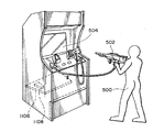
図1に、本実施形態を業務用ゲームシステムに適用した場合の構成例を示す。
【0022】
プレーヤ500は、本物のマシンガンを模して作られたガン型コントローラ(広義にはシューティングデバイス)502を構える。そして、画面504に映し出される敵キャラクタ(広義にはオブジェクト)などの標的オブジェクトを狙ってシューティングすることでガンゲームを楽しむ。
【0023】
特に、本実施形態のガン型コントローラ502は、引き金を引くと、仮想的なショット(弾)が高速で自動的に連射される。従って、あたかも本物のマシンガンを撃っているかのような仮想現実感をプレーヤに与えることができる。
【0024】
なお、ショットのヒット位置(着弾位置)は、ガン型コントローラ502に光センサを設け、この光センサを用いて画面の走査光を検知することで検出してもよいし、ガン型コントローラ502から光(レーザー光)を発射し、この光の照射位置をCCDカメラなどを用いて検知することで検出してもよい。
【0025】
図2に、本実施形態のブロック図の一例を示す。なお同図において本実施形態は、少なくとも処理部100を含めばよく(或いは処理部100と記憶部140、或いは処理部100と記憶部140と情報記憶媒体150を含めばよく)、それ以外のブロック(例えば操作部130、画像生成部160、表示部162、音生成部170、音出力部172、通信部174、I/F部176、メモリーカード180等)については、任意の構成要素とすることができる。
【0026】
ここで処理部100は、システム全体の制御、システム内の各ブロックへの命令の指示、ゲーム演算などの各種の処理を行うものであり、その機能は、CPU(CISC型、RISC型)、DSP、或いはASIC(ゲートアレイ等)などのハードウェアや、所与のプログラム(ゲームプログラム)により実現できる。
【0027】
操作部130は、プレーヤが操作データを入力するためのものであり、その機能は、図1のガン型コントローラ502、レバー、ボタンなどのハードウェアにより実現できる。
【0028】
記憶部140は、処理部100、画像生成部160、音生成部170、通信部174、I/F部176などのワーク領域となるもので、その機能はRAMなどのハードウェアにより実現できる。
【0029】
情報記憶媒体(コンピュータにより使用可能な記憶媒体)150は、プログラムやデータなどの情報を格納するものであり、その機能は、光ディスク(CD、DVD)、光磁気ディスク(MO)、磁気ディスク、ハードディスク、磁気テープ、或いは半導体メモリ(ROM)などのハードウェアにより実現できる。処理部100は、この情報記憶媒体150に格納される情報に基づいて本発明(本実施形態)の種々の処理を行う。即ち情報記憶媒体150には、本発明(本実施形態)の手段(特に処理部100に含まれるブロック)を実現(実行)するための種々の情報(プログラム、データ)が格納される。
【0030】
なお、情報記憶媒体150に格納される情報の一部又は全部は、システムへの電源投入時等に記憶部140に転送されることになる。また情報記憶媒体150に記憶される情報は、本発明の処理を行うためのプログラムコード、画像情報、音情報、表示物の形状情報、テーブルデータ、リストデータ、プレーヤ情報や、本発明の処理を指示するための情報、その指示に従って処理を行うための情報等の少なくとも1つを含むものである。
【0031】
画像生成部160は、処理部100からの指示等にしたがって、各種の画像を生成し表示部162に出力するものであり、その機能は、画像生成用ASIC、CPU、或いはDSPなどのハードウェアや、所与のプログラム(画像生成プログラム)、画像情報により実現できる。
【0032】
音生成部170は、処理部100からの指示等にしたがって、各種の音を生成し音出力部172に出力するものであり、その機能は、音生成用ASIC、CPU、或いはDSPなどのハードウェアや、所与のプログラム(音生成プログラム)、音情報(波形データ等)により実現できる。
【0033】
通信部174は、外部装置(例えばホスト装置や他の画像生成システム)との間で通信を行うための各種の制御を行うものであり、その機能は、通信用ASIC、或いはCPUなどのハードウェアや、所与のプログラム(通信プログラム)により実現できる。
【0034】
なお本発明(本実施形態)の処理を実現するための情報は、ホスト装置(サーバー)が有する情報記憶媒体からネットワーク及び通信部174を介して情報記憶媒体150に配信するようにしてもよい。このようなホスト装置(サーバー)の情報記憶媒体の使用も本発明の範囲内に含まれる。
【0035】
また処理部100の機能の一部又は全部を、画像生成部160、音生成部170、又は通信部174の機能により実現するようにしてもよい。或いは、画像生成部160、音生成部170、又は通信部174の機能の一部又は全部を、処理部100の機能により実現するようにしてもよい。
【0036】
I/F部176は、処理部100からの指示等にしたがってメモリーカード(広義には、携帯型ゲーム機などを含む携帯型情報記憶装置)180との間で情報交換を行うためのインターフェースとなるものであり、その機能は、メモリーカードを挿入するためのスロットや、データ書き込み・読み出し用コントローラICなどにより実現できる。なお、メモリーカード180との間の情報交換を赤外線などの無線を用いて実現する場合には、I/F部176の機能は、半導体レーザ、赤外線センサーなどのハードウェアにより実現できる。
【0037】
処理部100は、ゲーム演算部110を含む。
【0038】
ここでゲーム演算部110は、コイン(代価)の受け付け処理、各種モードの設定処理、ゲームの進行処理、選択画面の設定処理、オブジェクト(キャラクタ、移動体)の位置や回転角度(X、Y又はZ軸回り回転角度)を決める処理、視点位置や視線角度を決める処理、オブジェクトのモーションを再生又は生成する処理、オブジェクト空間へオブジェクトを配置する処理、ヒットチェック処理、ゲーム結果(成果、成績)を演算する処理、複数のプレーヤが共通のゲーム空間でプレイするための処理、或いはゲームオーバー処理などの種々のゲーム演算処理を、操作部130からの操作データ、メモリーカード180からのデータ、ゲームプログラムなどに基づいて行う。
【0039】
ゲーム演算部110は、ヒットチェック部112、モーション再生部114、モーション生成部116、切り替え部122、行動制御部124を含む。
【0040】
ここで、ヒットチェック部112は、ガン型コントローラを用いてプレーヤが発射したショットがオブジェクトにヒットしたか否かを調べるヒットチェック処理を行う。なお、処理負担の軽減化のためには、オブジェクトの形状を簡易化した簡易オブジェクトを用いてヒットチェック処理を行うことが望ましい。
【0041】
モーション再生部114は、オブジェクト(コンピュータが操作するコンピュータオブジェクト、プレーヤが操作するプレーヤオブジェクト等)のモーションを、モーションデータ記憶部142に記憶されているモーションデータに基づいて再生する処理を行う。即ち、モーションデータ記憶部142には、オブジェクトの各基準モーションでの各部位(パーツ)の位置データや角度データを含むモーションデータが記憶されている。モーション再生部114は、このモーションデータを読み出し、このモーションデータに基づいてオブジェクトの各部位を動かすことで、オブジェクトのモーションを再生する。
【0042】
モーション生成部116は、オブジェクトのモーションを、物理シミュレーション(物理計算を利用したシミュレーション。物理計算は擬似的な物理計算でもよい)により生成する処理を行う。即ち本実施形態では、ヒット(被弾)時等における、オブジェクトのモーションを、モーションデータに基づくモーション再生ではなく、物理シミュレーションによりリアルタイムに生成するようにしている。このように物理シミュレーションによりモーションを生成することで、モーションデータに基づくモーション再生に比べて、バラエティ度が高くリアルなモーション表現を、使用データ量を抑えながら実現できるようになる。
【0043】
モーション生成部116は、ヒット(被弾)時モーション生成部118と下半身モーション生成部120を含む。
【0044】
ここで、ヒット時モーション生成部118は、ヒット時におけるオブジェクトのモーションを生成する処理を行う。より具体的には、オブジェクトの第Nの部位がヒットされた場合には、ヒット情報(ヒット方向を向く力ベクトル等)に基づく物理シミュレーションにより、その第Nの部位を動かすと共に、隣の第N+1、第N+2、第N+3の部位等にヒット情報を順次伝達(伝搬)する(例えばその大きさを順次減衰させながら伝達する)。そして、伝達されたヒット情報に基づく物理シミュレーションにより、これらの第N+1、第N+2、第N+3の部位等を動かす。このようにしてオブジェクトのモーションを生成すれば、高速連射によりショットが連続してヒットした場合におけるオブジェクトのリアルなモーションを、少ない処理負担で表現できるようになる。
【0045】
また下半身モーション生成部120は、ヒット時のオブジェクトのよろけ動作をリアルに表現するために、オブジェクトの下半身についてのモーションを特別なアルゴリズムを用いて生成している。より具体的には、接地している第1の部位(例えば左足)を支点として倒れるようにオブジェクトを動かす。そして、オブジェクトが倒れるのを制限する位置(例えば仮想重心を接地面に投影した位置に関して第1の部位と点対称の位置)に、接地していない第2の部位(例えば右足)の移動目標位置を設定し、この移動目標位置に第2の部位を移動させる。このようにしてオブジェクトのモーションを生成すれば、よろけながらもなかなか倒れないというオブジェクトのモーション表現が可能になる。
【0046】
切り替え部122は、例えばオブジェクトがヒットされた場合に、モーション再生からモーション生成に切り替える処理を行う。或いは、所与の条件が成立した場合(ヒットされてから所与の時間が経過したり、体力パラメータが零になった場合)に、モーション生成からモーション再生に切り替える処理を行う。このようにすれば、モーション生成による表現が難しい場面では、モーション再生によりオブジェクトの動きを表現し、少ないデータ量でバラエティ度の高い動きが要請される場面では、モーション生成によりオブジェクトの動きを表現できるようになる。
【0047】
行動制御部124は、コンピュータが操作するコンピュータオブジェクトの行動を制御する処理を行う。より具体的には、コンピュータオブジェクト(敵キャラクタ等)と、プレーヤの視点(又はプレーヤが操作するプレーヤオブジェクト)との間に、介在オブジェクト(障害物、他の敵キャラクタ)が介在するか否かを判断する。そして、その判断結果に基づいてコンピュータオブジェクトの行動を制御する。例えば、コンピュータオブジェクトのプレーヤに対するアクション(攻撃等)を禁止(又は制限)したり、所与の移動位置(プレーヤにアクションを加えるのに適切な位置)にコンピュータオブジェクトを移動させる。或いは、介在オブジェクトが、他のコンピュータオブジェクトであった場合には、この他のコンピュータオブジェクトが消滅するまで、コンピュータオブジェクトを待機させる。以上のようにすることで、コンピュータオブジェクトからのアクションが、介在オブジェクトを通り抜ける等してプレーヤに加えられる事態を防止できる。
【0048】
なお、本実施形態の画像生成システムは、1人のプレーヤのみがプレイできるシングルプレーヤモード専用のシステムにしてもよいし、このようなシングルプレーヤモードのみならず、複数のプレーヤがプレイできるマルチプレーヤモードも備えるシステムにしてもよい。
【0049】
また複数のプレーヤがプレイする場合に、これらの複数のプレーヤに提供するゲーム画像やゲーム音を、1つの端末を用いて生成してもよいし、ネットワーク(伝送ライン、通信回線)などで接続された複数の端末を用いて生成してもよい。
【0050】
2.本実施形態の特徴
さて、本実施形態では、図3に示すように、敵キャラクタ(コンピュータオブジェクト)10が、複数の部位(右手12、右前腕14、右上腕16、胸18、腰20、左手22、左前腕24、左上腕26、頭30、右足32、右すね34、右股36、左足42、左すね44、左股46)により構成されている。なお、これらの部位(パーツ)の位置や回転角度(方向)は、スケルトンモデルを構成する関節J0〜J13の位置や骨(アーク)A0〜A18の回転角度として表すことができる。但し、これらの骨、関節は仮想的なものであり、現実に表示されるオブジェクトではない。
【0051】
本実施形態では、敵キャラクタを構成する部位が親子(階層)構造を有している(実際には関節が親子構造を有する)。即ち、手12、22の親は前腕14、24であり、前腕14、24の親は上腕16、26であり、上腕16、26の親は胸18であり、胸18の親は腰20となる。また、頭30の親は胸18となる。また、足32、42の親はすね34、44であり、すね34、44の親は股36、46であり、股36、46の親は腰20となる。
【0052】
モーションデータ記憶部には、これらの部位(関節、骨)の位置及び回転角度が、モーションデータとして記憶されている。例えば、歩きモーションが、MP0、MP1、MP2・・・・MPNという基準モーションにより構成されているとする。するとこれらの各基準モーションMP0、MP1、MP2・・・・MPNでの各部位の位置及び回転角度が、モーションデータとして予め記憶されている。そして、例えば基準モーションMP0の各部位の位置及び回転角度を読み出し、次に基準モーションMP1の各部位の位置及び回転角度を読み出すというように、基準モーションのモーションデータを時間経過に伴い順次読み出すことで、モーション再生が実現される。
【0053】
なお、モーションデータ記憶部に記憶するモーションデータは、一般的には、モーションキャプチャにより取得したり、デザイナが作成する。また、部位(関節、骨)の位置、回転角度は、親の部位の位置、回転角度に対する相対的な位置、相対的な回転角度で表される。
【0054】
本実施形態では、ヒット時における敵キャラクタ(コンピュータオブジェクト)のモーションを、物理シミュレーションを用いて生成している。
【0055】
例えば図4において、敵キャラクタの前腕14にプレーヤのショット(弾)がヒットすると、まず、ヒット力ベクトルFH0(広義にはヒット情報)に基づき前腕14を動かす(回転させる、移動させる)。更に、このヒット力ベクトルFH0を、FH1、FH2、FH3、FH4として親の部位である上腕16、胸18、腰20に順次伝達(伝搬)する。そして、伝達されたヒット力ベクトルFH1〜FH4により、上腕16、胸18、腰20を動かす。本実施形態では、このようにして、ヒット時における敵キャラクタのモーションをリアルタイムに生成している。
【0056】
より具体的には、ヒット力ベクトルFH0は、その方向が、ヒットの方向(ショットの軌道方向)に向き、その大きさが、ヒットの威力を表すベクトルである。そして、関節J1とヒット位置(着弾位置)HPを結ぶベクトルHVと、ヒット力ベクトルFH0との外積をとることで、回転モーメントが求められる。
【0057】
次に、この回転モーメントと前腕14の仮想質量に基づき、前腕14の角加速度が算出される。そして、算出された角加速度に基づき、前腕14の角速度が算出され、この角速度で前腕14がR0に示すように回転する。
【0058】
ヒット力ベクトルFH0(ヒット情報)は、その大きさが減衰されてFH1として親の部位である上腕16に伝達される。より具体的には、このFH1は関節J1に作用し、このFH1による回転モーメントで、上腕16がR1に示すように回転する。
【0059】
次に、胸18に伝達されたFH2は関節J2に作用し、このFH2による回転モーメントで、胸18がR2に示すように回転する。
【0060】
次に腰20に伝達されたFH3は関節J3に作用し、このFH3による回転モーメントで、腰20がR3に示すように回転する。また、腰20に伝達されたFH4は代表点RPに作用し、このFH4により、腰20がMT0に示すように移動する。なお、腰20がMT0の方向に移動すると、腰20以外の他の部位もMT0の方向に移動することになる。但し、この場合にも、腰20と他の部位との間の相対的な位置関係は変化しない。
【0061】
以上の手法によれば、ヒット時における敵キャラクタのリアルなモーションを生成できる。そして、生成されるモーションは、ヒット位置やヒット方向やヒット力の大きさなどに応じて異なったものとなり、モーションデータに基づくモーション再生の手法に比べて、モーションのバリエーションを格段に増すことができる。
【0062】
なお、本実施形態では、敵キャラクタのヒット時に、モーションデータに基づくモーション再生から物理シミュレーションによるモーション生成に切り替えている。
【0063】
例えば図5(A)のE1に示すように、敵キャラクタがヒットされる前においては、モーションデータに基づくモーション再生により敵キャラクタの動きが表現される。
【0064】
一方、E2に示すように、敵キャラクタがヒットされると、モーション再生からモーション生成に切り替わる。即ち、例えば図4で説明したようなモーション生成手法により、ヒット時の敵キャラクタの動きを表現する。
【0065】
また本実施形態では、所与の条件が成立した場合には、今度は、物理シミュレーションによるモーション生成からモーションデータに基づくモーション再生に切り替えている。
【0066】
例えば図5(A)のE3では、ヒット後に所与の時間TMが経過したため、モーション生成からモーション再生に切り替えている。
【0067】
即ち、E4のように短時間で連続して敵キャラクタにショットがヒットしている場合には、図4で説明したようなモーション生成により敵キャラクタを動かす。これにより、ショットがヒットする毎にヒット位置やヒット方向に応じてその動きが細かく変化する敵キャラクタを表現できる。
【0068】
一方、E3のように、ショットがヒットした後に所与の時間TMが経過した場合には、敵キャラクタに対する連射はもはや行われていないと考えられる。従って、この場合には、ヒット時のモーションから復帰する行動を敵キャラクタに行わせる。
【0069】
また図5(B)のE5では、敵キャラクタの体力パラメータが0(所与の値)になったため、モーション生成からモーション再生に切り替えている。即ち、この場合には、敵キャラクタを完全に転倒させるモーションを再生し、敵キャラクタを消滅させる。
【0070】
更に本実施形態では、ヒット時における敵キャラクタのよろけ動作を表現するために、敵キャラクタの下半身については、特別なアルゴリズムによりそのモーションを生成している。より具体的には、接地している方の足(第1の部位)を支点として倒れるように敵キャラクタ(オブジェクト)が動くと共に、敵キャラクタが倒れるのを制限する位置に、接地していない方の足(第2の部位)が移動するように、敵キャラクタのモーションを生成している。
【0071】
例えば図6のG1では、左足50が接地しており、右足52が非接地になっている。この場合には、FD0に示すように、接地している左足50を支点として倒れる(傾く)ように敵キャラクタの下半身を動かす。更に、敵キャラクタが倒れるのを制限する位置(支える位置)である移動目標位置54に、非接地の右足52を移動させる。
【0072】
そして、図6のG2に示すように両足50、52が接地すると、腰60から遠い方の足である左足50を浮かせる。次に、G3のFD1に示すように、接地している右足52を支点として倒れるように敵キャラクタの下半身を動かすと共に、敵キャラクタが倒れるのを制限する移動目標位置56に、非接地の左足50を移動させる。そして、G4に示すように両足50、52が接地する。
【0073】
このようにすることで、ショットの連続ヒットにより敵キャラクタがよろけながら後ずさりする様子をリアルに表現できるようになる。
【0074】
即ち、前述の図4の手法でヒット時におけるモーションを生成すると、ショットのヒットにより敵キャラクタがバランスを崩して、不自然な姿勢で床(接地面)に立ったままになるという事態が生じる。例えば、敵キャラクタの右足だけがヒットされた場合には、右足だけが宙に浮いた状態で敵キャラクタが床に立ったままの状態になる可能性がある。
【0075】
図6の手法により敵キャラクタの下半身を特別なアルゴリズムで動作させれば、上記のような事態を防止できる。即ち、図6のG1に示すように右足52が宙に浮いた場合には、FD0に示すように敵キャラクタは倒れるように動くと共に、倒れるのを支える移動目標位置54に右足52が移動する。従って、敵キャラクタの右足52だけが長時間にわたり宙に浮いたままになるという事態が防止されると共に、ヒットの衝撃により敵キャラクタが後ずさりしたかのように見せることができるようになる。
【0076】
特に、敵キャラクタに連続してショットがヒットした場合には、この連続ヒットの衝撃により敵キャラクタが徐々に後ずさりしているかのように見せることができ、これまでにないリアルなモーションを生成できる。しかも、敵キャラクタの接地していない方の足は、倒れるのを支える位置に常に移動するようになる。従って、敵キャラクタは、体力パラメータが0にならない限り、転倒しないようになる。従って、マシンガンのように高速でショットを連射できるガンゲームに最適なモーション表現を実現できる。
【0077】
さて、以上のような手法により敵キャラクタのモーションをリアルタイムに生成すると、以下のような問題が生じることが判明した。
【0078】
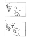
例えば図7(A)のように、プレーヤが操作するプレーヤキャラクタ(プレーヤオブジェクト)Pからの攻撃(ショット)が、敵キャラクタ(コンピュータオブジェクト)C1にヒットした場合を考える。この場合には、図4で説明した手法により、ヒット時における敵キャラクタC1のモーションが生成されることになる。そして、ヒットされた敵キャラクタC1は、図6で説明した下半身アルゴリズムにしたがって、よろめきながら任意の方向に移動することになる。
【0079】
そして、例えば図7(B)に示すように、障害物OBの陰に敵キャラクタC1が移動した場合を考える。このような状態で、敵キャラクタC1がプレーヤキャラクタPに攻撃を加えると、図8(A)に示すように、ショット(攻撃)が障害物OBを貫通してプレーヤ(プレーヤキャラクタP)にヒットしてしまう事態が生じる。即ち、敵キャラクタC1からの攻撃が、障害物OBにより妨げられることなく、プレーヤに対して加えられてしまう。
【0080】
また、図8(B)に示すように、敵キャラクタC1が他の敵キャラクタC2の後ろに移動してしまったような場合には、敵キャラクタC1からのショットが他の敵キャラクタC2を貫通してプレーヤ(プレーヤキャラクタP)にヒットしてしまう事態が生じる。
【0081】
図8(A)、(B)に示すような事態が生じると、プレーヤに大きな不快感を与えてしまう。プレーヤから見えない場所にいる敵キャラクタC1からのショットが、突然、障害物OBや他の敵キャラクタC2を突き抜けて、プレーヤにヒットしてしまうからである。
【0082】
そこで、本実施形態では、以下に述べるような手法を採用して、図8(A)、(B)で説明した不具合を解消している。
【0083】
即ち、まず、敵キャラクタとプレーヤの視点(又はプレーヤキャラクタ)との間に、障害物(介在オブジェクト)が介在するか否かを判断する。
【0084】
より具体的には、図9のH1に示すように、敵キャラクタC1と視点VP(又はプレーヤキャラクタP)とを結ぶ線を求め(敵キャラクタC1から視点VPに向かってレイを発射する)、その線上に障害物OBが存在するか否かを判断する。
【0085】
そして、その判断結果に基づいて、敵キャラクタの行動を制御し、敵キャラクタからの攻撃(アクション)がプレーヤに対して加えられないようする。
【0086】
より具体的には、図9のH2に示すように、まず、敵キャラクタC1のプレーヤ(プレーヤキャラクタP)に対する攻撃を禁止(又は制限)するようにする。そして、予め用意された移動位置P1、P2、P3、P4の中から、攻撃に適切(最適)な移動位置を選択する。図9のH2ではP4が選択されている。次に、図9のH3に示すように、選択された移動位置P4に敵キャラクタC1を移動させる。そして、攻撃が可能であると判断されると、H4に示すように、敵キャラクタC1はプレーヤに対する攻撃を開始する。
【0087】
図10(A)〜図12(B)に、本実施形態により生成されるゲーム画像の例を示す。
【0088】
図10(A)は、プレーヤからのショットが敵キャラクタC1にヒットしたゲーム場面である。このようにショットが敵キャラクタC1にヒットすると、図4で説明した手法により、敵キャラクタC1のヒット時のモーションが生成される。そして、図6で説明した下半身の動作アルゴリズムにしたがって、図10(B)に示すように、敵キャラクタC1がヒットの撃力によりよろめきながら移動することになる。
【0089】
図11(A)は、ヒットの撃力により移動した敵キャラクタC1が、障害物OBの陰に隠れて見えなくなってしまったゲーム場面である。この場合に、敵キャラクタC1が、プレーヤに対して反撃を行うと、C1からのショットが障害物OBを貫通してプレーヤにヒットするという不具合が生じてしまう。
【0090】
しかしながら、このような場合に本実施形態では、まず図9のH2で説明したように、敵キャラクタC1の攻撃が禁止される。そして、図9のH3で説明したように、敵キャラクタC1が適切な移動位置に移動する。図11(B)は、このように敵キャラクタC1が適切な移動位置に移動した状態を示すゲーム場面である。
【0091】
適切な移動位置に移動した敵キャラクタC1は、図12(A)に示すようにマシンガンを構えて、図12(B)に示すようにプレーヤに対して攻撃(反撃)を開始することになる。
【0092】
以上のような手法で敵キャラクタの行動を制御することで、敵キャラクタからのショットが障害物や他の敵キャラクタを貫通してプレーヤにヒットしてしまうという図8(A)、(B)の不具合を効果的に解消できるようになる。
【0093】
例えば図8(A)、(B)の不具合は、敵キャラクタの配置や移動ルートを工夫する手法により、ある程度解消できる。
【0094】
しかしながら、この手法を採用すると、敵キャラクタの配置や移動ルートのデザインに制限が加わり、ゲームステージの自由なデザインが妨げられてしまう。
【0095】
また、図4や図6で説明したように、本実施形態では敵キャラクタのモーションをリアルタイムに生成している。従って、敵キャラクタがどのように動くかを予め予期することができない。即ち、プレーヤがどのようなゲーム操作を行ったか(プレーヤがどの敵キャラクタをどのタイミングでどのように撃ったか)に応じて、敵キャラクタの移動位置や動きが異なったものになってしまう。従って、敵キャラクタの初期配置や移動ルートを如何に工夫しても、図7(B)に示すように敵キャラクタが障害物に隠れてしまうという状況が必然的に生じてしまう。
【0096】
しかしながら、本実施形態では、敵キャラクタの行動アルゴリズムに工夫を加えて図9に示すように敵キャラクタの行動を制御している。従って、図7(B)に示すような状況が生じても、ショットが障害物や他の敵キャラクタを貫通してプレーヤにヒットしてしまうという図8(A)、(B)の不具合を効果的に防止できるようになる。
【0097】
なお、敵キャラクタC1からのショットと、障害物OBや他の敵キャラクタとの間のヒットチェックを行い、C1からのショットがOBやC2を貫通しないようにすれば(C1からの攻撃が介在オブジェクトにより妨げられるようにすれば)、図8(A)、(B)の不具合は解消できる。
【0098】
しかしながら、この種のゲームでは、登場する敵キャラクタの数や障害物の数が非常に多い。従って、これらの多数の敵キャラクタ、障害物間での全てのヒットチェックを行おうとすると、処理負担が非常に重くなる。
【0099】
図9に示す本実施形態の手法によれば、敵キャラクタ、障害物間での全てのヒットチェックを行わない場合でも(敵キャラクタからの攻撃が介在オブジェクトにより妨げられることなくプレーヤに対して加えられる場合でも)、図8(A)、(B)の不具合が生じるのを防止できる。即ち、処理負担をそれほど増すことなく、図8(A)、(B)の不具合を解消できる。
【0100】
さて、本実施形態では、第1の敵キャラクタと視点(又はプレーヤキャラクタ)との間に介在するオブジェクトが、他の第2の敵キャラクタである場合には、第1の敵キャラクタを待機させるようにしている。
【0101】
より具体的には、図13のI1に示すように、敵キャラクタC1と視点VP(又はプレーヤキャラクタP)とを結ぶ線を求め、その線上に他の敵キャラクタC2が存在するか否かを判断する。
【0102】
そして、障害物OBが線上に存在すると判断した場合には、図13のI2に示すように、敵キャラクタC1の攻撃を禁止して、その場で待機させる。
【0103】
そして、図13のI3に示すようにプレーヤの攻撃で敵キャラクタC2が消滅した場合には、図13のI4に示すように、敵キャラクタC1にプレーヤを攻撃させる。
【0104】
即ち、図13のI1に示すようにプレーヤから見て敵キャラクタC1、C2が重なった場合には、敵キャラクタC1の前にいる敵キャラクタC2については、プレーヤの攻撃により消滅する可能性が非常に高い。そして、敵キャラクタC2が消滅すれば、図8(B)で説明したような不具合は自然に解消してしまう。従って、このような場合には、図9のような敵キャラクタC1の移動処理は必要なく、その場で敵キャラクタC1を待機させれば十分となる。そして、敵キャラクタC1の移動処理を行わないようにすれば、処理負担の軽減化を図れるという利点が得られる。
【0105】
また、本実施形態では、敵キャラクタがプレーヤの視野外に移動した場合には、その敵キャラクタを消滅させるようにしている。
【0106】
例えば、図14のK1に示すようにプレーヤからの攻撃が敵キャラクタC1にヒットし、図14のK2に示すように敵キャラクタC1がプレーヤの視界外(画面外)に移動した場合を考える。このような場合に、図14のK3に示すように本実施形態では、敵キャラクタC1を消滅させる。このようにすることで、敵キャラクタC1が視野外からプレーヤに攻撃を加えてくるという事態を効果的に防止できる。
【0107】
即ち、本実施形態では、図4で説明したようにヒット時の敵キャラクタのモーションをリアルタイムに生成しており、図6で説明したようにヒットの撃力により敵キャラクタがよろめきながら任意の方向に移動する。従って、プレーヤからの攻撃により、敵キャラクタが視野外に移動してしまう事態が生じる。そして、このように視野外に移動してしまった敵キャラクタからの攻撃を許すと、見えない敵キャラクタからプレーヤが攻撃されることになってしまい、図8(A)、(B)と同様の不快感をプレーヤに与えてしまう。
【0108】
そこで、図14のK3に示すように本実施形態では、視野外の敵キャラクタC1を消滅させるようにしている。このようにすれば、見えない敵キャラクタからプレーヤが攻撃されてしまうという事態を防止でき、プレーヤのゲームへの没入度、熱中度を維持できるようになる。
【0109】
3.本実施形態の処理
次に、本実施形態の詳細な詳細例について、図15、図16のフローチャートを用いて説明する。
【0110】
図15は、本実施形態の全体的な処理の流れを示すフローチャートである。
【0111】
まず、モーションデータに基づくモーション再生を行う(ステップS1)。
【0112】
次に、プレーヤからのショットがヒットしたか否かを判断し(ステップS2)、ヒットしなかった場合には、ステップS1に戻りモーション再生を続行する。一方、ヒットした場合には、体力パラメータが0か否かを判断する(ステップS3)。そして、体力パラメータが0でない場合には、図5(A)のE2に示すように、物理シミュレーションによるモーション生成処理に移行する(ステップS4)。
【0113】
次に、ヒット後から所与の時間が経過したか否かを判断し(ステップS5)、経過していない場合には、プレーヤからのショットがヒットしたか否かを判断する(ステップS6)。そして、ヒットした場合には、ステップS3で体力パラメータが0か否かを判断し、0でない場合にはステップS4のモーション生成処理を続行する。一方、ヒットしなかった場合には、ステップS3の体力パラメータの判断処理を行うことなく、ステップS4のモーション生成処理を続行する。
【0114】
ステップS5で所与の時間が経過したと判断された場合には、図9で説明したような敵キャラクタの復帰行動処理を行う(ステップS7)。即ち、ヒット時のモーションから復帰する行動を敵キャラクタに行わせ、モーション再生処理に切り替える。
【0115】
ステップS3で、体力パラメータが0であると判断された場合には、転倒モーションへの繋ぎモーションを再生(又は生成)する(ステップS8)。そして、図5(B)のE5に示すように、転倒モーションの再生処理に移行し(ステップS9)、敵キャラクタを消滅させる(ステップS10)。
【0116】
図16は、図15のステップS7の復帰行動処理(敵キャラクタの行動アルゴリズム)に関するフローチャートである。
【0117】
まず、自身(敵キャラクタ)の現在位置を確認する(ステップT1)。そして、現在位置が画面外(視野外)か否かを判断し(ステップT2)、画面外である場合には、図14のK3で説明したように自身(敵キャラクタ)を消滅させる(ステップT3)。
【0118】
次に、現在位置が画面端か否かを判断し(ステップT4)、画面端である場合には、予め設定された移動ポイントの中から最適な移動ポイントを選択して移動する(ステップT5)。
【0119】
次に、現在位置と視点とを結ぶ線(レイ)上に介在オブジェクト(障害物、他の敵キャラクタ)が存在するかを判断する(ステップT6)。そして、図9のH1のように障害物が線上に存在する場合には、図9のH2、H3のように攻撃を行うことなく最適の移動ポイントに移動する(ステップT7、T5)。また、図13のI1のように他の敵キャラクタが線上に存在する場合には、図13のI2、I3のように、他の敵キャラクタが消滅するまでその場で待機する(ステップT8、T9)。
【0120】
そして、介在オブジェクト(障害物、他の敵キャラクタ)が線上に存在しなくなったら、図9のH4、図13のI4のように、プレーヤに対する攻撃を開始する(ステップT10)。
【0121】
4.ハードウェア構成
次に、本実施形態を実現できるハードウェアの構成の一例について図17を用いて説明する。同図に示すシステムでは、CPU1000、ROM1002、RAM1004、情報記憶媒体1006、音生成IC1008、画像生成IC1010、I/Oポート1012、1014が、システムバス1016により相互にデータ送受信可能に接続されている。そして前記画像生成IC1010にはディスプレイ1018が接続され、音生成IC1008にはスピーカ1020が接続され、I/Oポート1012にはコントロール装置1022が接続され、I/Oポート1014には通信装置1024が接続されている。
【0122】
情報記憶媒体1006は、プログラム、表示物を表現するための画像データ、音データ等が主に格納されるものである。例えば家庭用ゲームシステムではゲームプログラム等を格納する情報記憶媒体としてDVD、ゲームカセット、CDROM等が用いられる。また業務用ゲームシステムではROM等のメモリが用いられ、この場合には情報記憶媒体1006はROM1002になる。
【0123】
コントロール装置1022はゲームコントローラ、操作パネル等に相当するものであり、プレーヤがゲーム進行に応じて行う判断の結果をシステム本体に入力するための装置である。
【0124】
情報記憶媒体1006に格納されるプログラム、ROM1002に格納されるシステムプログラム(システム本体の初期化情報等)、コントロール装置1022によって入力される信号等に従って、CPU1000はシステム全体の制御や各種データ処理を行う。RAM1004はこのCPU1000の作業領域等として用いられる記憶手段であり、情報記憶媒体1006やROM1002の所与の内容、あるいはCPU1000の演算結果等が格納される。また本実施形態を実現するための論理的な構成を持つデータ構造は、このRAM又は情報記憶媒体上に構築されることになる。
【0125】
更に、この種のシステムには音生成IC1008と画像生成IC1010とが設けられていてゲーム音やゲーム画像の好適な出力が行えるようになっている。音生成IC1008は情報記憶媒体1006やROM1002に記憶される情報に基づいて効果音やバックグラウンド音楽等のゲーム音を生成する集積回路であり、生成されたゲーム音はスピーカ1020によって出力される。また、画像生成IC1010は、RAM1004、ROM1002、情報記憶媒体1006等から送られる画像情報に基づいてディスプレイ1018に出力するための画素情報を生成する集積回路である。なおディスプレイ1018として、いわゆるヘッドマウントディスプレイ(HMD)と呼ばれるものを使用することもできる。
【0126】
また、通信装置1024は画像生成システム内部で利用される各種の情報を外部とやりとりするものであり、他の画像生成システムと接続されてゲームプログラムに応じた所与の情報を送受したり、通信回線を介してゲームプログラム等の情報を送受することなどに利用される。
【0127】
そして図1〜図16で説明した種々の処理は、プログラムやデータなどの情報を格納した情報記憶媒体1006、この情報記憶媒体1006からの情報等に基づいて動作するCPU1000、画像生成IC1010或いは音生成IC1008等によって実現される。なお画像生成IC1010、音生成IC1008等で行われる処理は、CPU1000あるいは汎用のDSP等によりソフトウェア的に行ってもよい。
【0128】
図1に示すような業務用ゲームシステムに本実施形態を適用した場合には、内蔵されるシステムボード(サーキットボード)1106に対して、CPU、画像生成IC、音生成IC等が実装される。そして、本実施形態の処理(本発明の手段)を実行(実現)するための情報は、システムボード1106上の情報記憶媒体である半導体メモリ1108に格納される。以下、この情報を格納情報と呼ぶ。
【0129】
図18(A)に、本実施形態を家庭用のゲームシステムに適用した場合の例を示す。プレーヤはディスプレイ1200に映し出されたゲーム画像を見ながら、ゲームコントローラ1202、1204を操作してゲームを楽しむ。この場合、上記格納情報は、本体システムに着脱自在な情報記憶媒体であるDVD1206、メモリーカード1208、1209等に格納されている。
【0130】
図18(B)に、ホスト装置1300と、このホスト装置1300と通信回線(LANのような小規模ネットワークや、インターネットのような広域ネットワーク)1302を介して接続される端末1304-1〜1304-nとを含む画像生成システムに本実施形態を適用した場合の例を示す。この場合、上記格納情報は、例えばホスト装置1300が制御可能な磁気ディスク装置、磁気テープ装置、半導体メモリ等の情報記憶媒体1306に格納されている。端末1304-1〜1304-nが、CPU、画像生成IC、音処理ICを有し、スタンドアロンでゲーム画像、ゲーム音を生成できるものである場合には、ホスト装置1300からは、ゲーム画像、ゲーム音を生成するためのゲームプログラム等が端末1304-1〜1304-nに配送される。一方、スタンドアロンで生成できない場合には、ホスト装置1300がゲーム画像、ゲーム音を生成し、これを端末1304-1〜1304-nに伝送し端末において出力することになる。
【0131】
なお、図18(B)の構成の場合に、本発明の処理を、ホスト装置(サーバー)と端末とで分散して処理するようにしてもよい。また、本発明を実現するための上記格納情報を、ホスト装置(サーバー)の情報記憶媒体と端末の情報記憶媒体に分散して格納するようにしてもよい。
【0132】
また通信回線に接続する端末は、家庭用ゲームシステムであってもよいし業務用ゲームシステムであってもよい。そして、業務用ゲームシステムを通信回線に接続する場合には、業務用ゲームシステムとの間で情報のやり取りが可能であると共に家庭用ゲームシステムとの間でも情報のやり取りが可能な携帯型情報記憶装置(メモリーカード、携帯型ゲーム機)を用いることが望ましい。
【0133】
なお本発明は、上記実施形態で説明したものに限らず、種々の変形実施が可能である。
【0134】
例えば、本発明のうち従属請求項に係る発明においては、従属先の請求項の構成要件の一部を省略する構成とすることもできる。また、本発明の1の独立請求項に係る発明の要部を、他の独立請求項に従属させることもできる。
【0135】
また、本発明における介在オブジェクトは、図9、図13で説明したような障害物、敵キャラクタに限定されず、味方キャラクタ、移動体、マップオブジェクト等、種々のものを考えることができる。
【0136】
また、コンピュータオブジェクトの行動の制御手法も、図9、図13、図14で説明した手法には限定されず、種々の変形実施が可能である。
【0137】
また、本発明は、コンピュータオブジェクトのモーションが図4、図6のように物理シミュレーションによりリアルタイムに生成される場合に特に有効であるが、コンピュータオブジェクトのモーションを物理シミュレーションにより生成しない場合にも本発明は適用できる。
【0138】
また、本実施形態では、コンピュータオブジェクトと視点とを結ぶ線上に介在オブジェクトが存在するか否かで、介在オブジェクトの介在を判断したが、本発明の判断手法はこれに限定されるものではない。また、このような判断を行うことなく、コンピュータオブジェクトの行動を制御するようにしてもよい。
【0139】
またコンピュータオブジェクトの移動位置については、予め用意されたものから選択するようにしてもよいし、移動位置をリアルタイムに生成するようにしてもよい。
【0140】
また、コンピュータオブジェクトからプレーヤへのアクションは、コンピュータオブジェクトによる攻撃であることが特に望ましいが、本発明におけるアクションはこれに限定されない。例えば、本発明におけるアクションとしては、ショットの発射以外の攻撃(キック、パンチ等)、送球、パス、捕捉、或いは衝突等、種々のものを考えることができる。例えば図19(A)、(B)に本実施形態をサッカーゲームに適用した場合のゲーム画像例を示す。図19(A)では、選手70(コンピュータオブジェクト)が選手72(プレーヤオブジェクト)にパス(アクション)しようとしているが、選手70、72間に選手74(介在オブジェクト)が介在するためパスができない。そこで、このような場合には、選手70の動作アルゴリズムが、選手74の介在を検出して、図19(B)のように、パスが可能な移動位置に選手70を移動させ、選手72へパス(アクション)をするようにする。
【0141】
また、コンピュータオブジェクトは図4、図6で説明した手法によりそのモーションを生成することが望ましいが、これ以外の手法によりモーション生成してもよい。
【0142】
また、各部位を動かす物理シミュレーションの手法は、図4、図6などで説明した手法が特に望ましいが、これに限定されるものでなく種々の変形実施が可能である。また、ヒット情報は、処理の簡素化のためにはヒット力ベクトルであることが特に望ましいが、これに限定されるものではなく、少なくとも各部位を動かすための情報であればよい。
【0143】
また、本実施形態では、敵キャラクタについてのモーション生成やモーション再生について主に説明したが、モーション生成やモーション再生の対象となるオブジェクトは敵キャラクタに限定されず、プレーヤキャラクタや移動体など種々のオブジェクトを考えることができる。
【0144】
また、本実施形態では、ショットによりオブジェクトがヒットされる場合を例にとり説明したが、本発明におけるオブジェクトのヒットは、これに限定されず、例えば、剣によるヒットや、パンチやキックによるヒット等も含まれる。
【0145】
また本発明はガンゲーム以外にも種々のゲーム(ガンゲーム以外のシューティングゲーム、格闘ゲーム、ロボット対戦ゲーム、スポーツゲーム、競争ゲーム、ロールプレイングゲーム、音楽演奏ゲーム、ダンスゲーム等)に適用できる。
【0146】
また本発明は、業務用ゲームシステム、家庭用ゲームシステム、多数のプレーヤが参加する大型アトラクションシステム、シミュレータ、マルチメディア端末、画像生成システム、ゲーム画像を生成するシステムボード等の種々の画像生成システムに適用できる。
【図面の簡単な説明】
【図1】本実施形態を業務用ゲームシステムに適用した場合の構成例を示す図である。
【図2】本実施形態の画像生成システムのブロック図の例である。
【図3】複数の部位により構成される敵キャラクタ(オブジェクト)の例について示す図である。
【図4】本実施形態におけるヒット時のモーション生成手法について説明するための図である。
【図5】図5(A)、(B)は、モーション生成とモーション再生を切り替える手法について説明するための図である。
【図6】敵キャラクタの下半身モーションの生成について説明するための図である。
【図7】図7(A)、(B)は、ヒットされた敵キャラクタがよろめきながら障害物の陰に移動する状況について説明するための図である。
【図8】図8(A)、(B)は、敵キャラクタからの攻撃が障害物や他の敵キャラクタを貫通してプレーヤにヒットしてしまうという不具合について説明するための図である。
【図9】本実施形態による敵キャラクタの行動制御の手法について説明するための図である。
【図10】図10(A)、(B)は、本実施形態により生成されるゲーム画像の例について示す図である。
【図11】図11(A)、(B)も、本実施形態により生成されるゲーム画像の例について示す図である。
【図12】図12(A)、(B)も、本実施形態により生成されるゲーム画像の例について示す図である。
【図13】第1の敵キャラクタが他の第2の敵キャラクタの陰に隠れている場合には、第1の敵キャラクタを待機させる手法について説明するための図である。
【図14】プレーヤの視野外に移動した敵キャラクタを消滅させる手法について説明するための図である。
【図15】本実施形態の処理の詳細例について示すフローチャートである。
【図16】本実施形態の処理の詳細例について示すフローチャートである。
【図17】本実施形態を実現できるハードウェアの構成の一例を示す図である。
【図18】図18(A)、(B)は、本実施形態が適用される種々の形態のシステムの例を示す図である。
【図19】図19(A)、(B)は、本実施形態をサッカーゲームに適用した場合のゲーム画像例について示す図である。
【符号の説明】
10 敵キャラクタ(オブジェクト)
12、22 手
14、24 前腕
16、26 上腕
18 胸
20 腰
30 頭
32、42 足
34、44 すね
36、46 股
50 左足
52 右足
54、56 移動目標位置
60 腰
A0〜A18 骨
J0〜J13 関節
RP 代表点
FH0〜FH4 ヒット力ベクトル
P プレーヤキャラクタ
C1、C2 敵キャラクタ
OB 障害物
P1〜P4 移動ポイント
VP 視点
70、72、74 選手
100 処理部
110 ゲーム演算部
112 ヒットチェック部
114 モーション再生部
116 モーション生成部
118 ヒット時モーション生成部
120 下半身モーション生成部
122 切り替え部
124 行動制御部
130 操作部
140 記憶部
142 モーションデータ記憶部
150 情報記憶媒体
160 画像生成部
162 表示部
170 音生成部
172 音出力部
174 通信部
176 I/F部
180 メモリーカード[0001]
BACKGROUND OF THE INVENTION
The present invention relates to an image generation system and an information storage medium.
[0002]
[Background Art and Problems to be Solved by the Invention]
2. Description of the Related Art Conventionally, an image generation system that generates an image that can be seen from a given viewpoint in an object space that is a virtual three-dimensional space is known, and is popular as being able to experience so-called virtual reality. Taking an image generation system that can enjoy a gun game as an example, a player (operator) uses a gun-type controller (shooting device) imitating a gun or the like to display enemy characters (screened on the screen). Enjoy 3D games by shooting target objects such as computer objects.
[0003]
Now, in developing an image generation system that can enjoy such a gun game, it has been found that there are the following problems.
[0004]
That is, when there is an obstacle between the player (player object) and the enemy character, a shot (bullet) from the enemy character penetrates the obstacle and hits the player. When such a problem occurs, the player feels uncomfortable, resulting in a serious loss of the player's degree of enthusiasm and immersion in the game.
[0005]
Such a problem can be solved to some extent by, for example, a technique for devising the arrangement and movement route of enemy characters. However, such a solution has its limitations.
[0006]
Especially when the action of the enemy character is not uniquely determined in advance, that is, when the action of the enemy character is completely different depending on how the shot from the player hits the enemy character. The above-mentioned problems cannot be solved by a technique for devising the arrangement of enemy characters and the moving route.
[0007]
The present invention has been made in view of the above problems, and an object of the present invention is to provide an image generation system and an information storage medium that can realize a real image that does not give the player unnatural feeling with a small processing load. Is to provide.
[0008]
[Means for Solving the Problems]
In order to solve the above problems, the present invention provides an image generation system for generating an image, wherein an intervening object is provided between a first computer object operated by a computer and a player object or viewpoint operated by a player. And means for determining whether or not to intervene, and controlling the action of the first computer object based on the determination result, and means for generating an image including an image of the first computer object. . The information storage medium according to the present invention is an information storage medium that can be used by a computer, and includes information (program or data) for realizing (executing) the above means. A program according to the present invention is a program (including a program embodied in a carrier wave) usable by a computer, and includes a processing routine for realizing (executing) the above means.
[0009]
According to the present invention, it is determined whether an intervening object is interposed between the first computer object and the player object or the viewpoint. Then, the action of the first computer object is controlled according to the determination result. In this way, even if some trouble occurs due to the intervention of the intervening object, such trouble can be solved by appropriately controlling the behavior of the first computer object. In this case, for example, it is desirable to control the behavior of the first computer object so that an action from the first computer object is not applied to the player.
[0010]
The image generation system, the information storage medium, and the program according to the present invention determine whether or not an intervening object exists on a line connecting the first computer object and the player object or the viewpoint. It is characterized in that it is determined whether or not an intervening object is interposed between the player object and the viewpoint. In this way, it is possible to detect the intervention of the intervening object with a simple process of simply determining whether the intervening object exists on the line.
[0011]
The present invention is also an image generation system for generating an image, in which an intervening object is interposed between a first computer object operated by a computer and a player object or viewpoint operated by a player. Means for preventing an action from the computer object from being applied to the player, and means for generating an image including an image of the first computer object. The information storage medium according to the present invention is an information storage medium that can be used by a computer, and includes information (program or data) for realizing (executing) the above means. A program according to the present invention is a program (including a program embodied in a carrier wave) usable by a computer, and includes a processing routine for realizing (executing) the above means.
[0012]
According to the present invention, when an intervening object is interposed between the first computer object and the player object or the viewpoint, the action from the first computer object is not applied to the player. As a result, it is possible to solve the problem that the action is applied to the player by passing through the intervening object (penetration, passage) or the like.
[0013]
The image generation system, information storage medium, and program according to the present invention prohibit the action of the first computer object on the player when the intervening object is interposed between the first computer object and the player object or the viewpoint. Or it is characterized by limiting. In this way, it is possible to prevent or limit a problem that an action from the first computer object is applied to the player by passing through the intervening object.
[0014]
The image generation system, the information storage medium, and the program according to the present invention are arranged such that when an intervening object is interposed between the first computer object and the player object or the viewpoint, the first computer object is moved to a given moving position. It is made to move to. In this way, the first computer object can be moved to a moving position suitable for applying an action to the player, and an image that does not give the player an unnatural feeling can be generated.
[0015]
The image generation system, information storage medium, and program according to the present invention are characterized in that when the intervening object is a second computer object operated by a computer, the first computer object is made to wait. That is, for example, the first computer object is made to wait on the spot until the second computer object disappears. In this way, it is possible to naturally solve the problem caused by the intervention of the second computer object without performing processing such as moving the first computer object.
[0016]
The image generation system, information storage medium, and program according to the present invention are characterized in that the first computer object disappears when the first computer object moves out of the field of view of the player. In this way, an action from the first computer object that has moved out of the player's field of view can be added to the player, preventing the player from feeling unnatural.
[0017]
The image generation system, information storage medium, and program according to the present invention are characterized in that the first computer object is an object whose motion is generated by a physical simulation. In this way, various motions of the first computer object that require a large amount of motion data depending on motion reproduction can be realized with a small amount of data using motion generation. When the motion of the first computer object is generated by the physical simulation in this way, the moving position of the first computer object cannot be predicted in advance, and the first computer object is not between the player object or the viewpoint. The problem that intervening objects intervene arises. However, according to the present invention, such a problem can be effectively solved by appropriately controlling the behavior of the first computer object.
[0018]
The image generation system, the information storage medium, and the program according to the present invention can generate the first computer object when a motion of the first computer object at the time of the hit is generated by a physical simulation and a given time elapses after the hit. It is determined whether or not an intervening object is present between the player object or the viewpoint and the behavior of the first computer object is controlled based on the determination result. In this way, even if a situation occurs in which the first computer object moves to an unexpected movement position due to a hitting force or the like due to a hit, such a determination is made based on the determination result of whether or not the intervening object exists. You will be able to deal with the situation appropriately.
[0019]
In the image generation system, information storage medium, and program according to the present invention, the first computer object is an object that attacks the player, and the attack from the first computer object is prevented by the intervening object. It is characterized by being added to the player without any change. As described above, when an attack from the first computer object is transmitted to the player without being interrupted by the intervening object, there is a problem that the player is attacked by passing through the intervening object. However, according to the present invention, such a problem can be effectively solved by appropriately controlling the behavior of the first computer object.
[0020]
DETAILED DESCRIPTION OF THE INVENTION
Hereinafter, preferred embodiments of the present invention will be described with reference to the drawings. Hereinafter, a case where the present invention is applied to a gun game (shooting game) using a gun-type controller will be described as an example. However, the present invention is not limited to this and can be applied to various games.
[0021]
1. Constitution
FIG. 1 shows a configuration example when the present embodiment is applied to an arcade game system.
[0022]
The
[0023]
In particular, when the gun-
[0024]
The shot hit position (landing position) may be detected by providing an optical sensor in the gun-
[0025]
FIG. 2 shows an example of a block diagram of the present embodiment. In this figure, the present embodiment may include at least the processing unit 100 (or may include the
[0026]
Here, the
[0027]
The
[0028]
The
[0029]
An information storage medium (storage medium usable by a computer) 150 stores information such as programs and data, and functions thereof are an optical disk (CD, DVD), a magneto-optical disk (MO), a magnetic disk, and a hard disk. It can be realized by hardware such as a magnetic tape or a semiconductor memory (ROM). The
[0030]
Part or all of the information stored in the
[0031]
The
[0032]
The
[0033]
The
[0034]
Note that information for realizing the processing of the present invention (this embodiment) may be distributed from the information storage medium of the host device (server) to the
[0035]
Further, part or all of the functions of the
[0036]
The I /
[0037]
The
[0038]
Here, the
[0039]
The
[0040]
Here, the
[0041]
The
[0042]
The
[0043]
The
[0044]
Here, the hit
[0045]
In addition, the lower body
[0046]
For example, when the object is hit, the
[0047]
The
[0048]
Note that the image generation system of the present embodiment may be a system dedicated to the single player mode in which only one player can play, or not only the single player mode but also a multiplayer mode in which a plurality of players can play. The system may also be provided.
[0049]
Further, when a plurality of players play, game images and game sounds to be provided to the plurality of players may be generated using one terminal, or connected via a network (transmission line, communication line) or the like. Alternatively, it may be generated using a plurality of terminals.
[0050]
2. Features of this embodiment
In this embodiment, as shown in FIG. 3, the enemy character (computer object) 10 has a plurality of parts (
[0051]
In this embodiment, the parts constituting the enemy character have a parent-child (hierarchical) structure (actually, the joint has a parent-child structure). That is, the parents of the
[0052]
The motion data storage unit stores the positions and rotation angles of these parts (joints and bones) as motion data. For example, it is assumed that the walking motion is composed of reference motions MP0, MP1, MP2,... MPN. Then, the position and rotation angle of each part in each of these reference motions MP0, MP1, MP2,... MPN are stored in advance as motion data. Then, by sequentially reading out the motion data of the reference motion as time elapses, for example, reading the position and rotation angle of each part of the reference motion MP0 and then reading the position and rotation angle of each part of the reference motion MP1. , Motion playback is realized.
[0053]
The motion data stored in the motion data storage unit is generally acquired by motion capture or created by a designer. The position and rotation angle of the part (joint and bone) are represented by the position of the parent part, the relative position with respect to the rotation angle, and the relative rotation angle.
[0054]
In this embodiment, the motion of the enemy character (computer object) at the time of a hit is generated using a physical simulation.
[0055]
For example, in FIG. 4, when a player's shot (bullet) hits the
[0056]
More specifically, the hit force vector FH0 is a vector whose direction is in the hit direction (shot trajectory direction), and whose magnitude represents the hit power. Then, the rotational moment is obtained by taking the outer product of the vector HV connecting the joint J1 and the hit position (landing position) HP and the hit force vector FH0.
[0057]
Next, the angular acceleration of the
[0058]
The magnitude of the hit force vector FH0 (hit information) is attenuated and transmitted to the
[0059]
Next, FH2 transmitted to the
[0060]
Next, FH3 transmitted to the
[0061]
According to the above method, the realistic motion of the enemy character at the time of a hit can be generated. The generated motion differs depending on the hit position, hit direction, and hit power, and the number of motion variations can be greatly increased compared to the motion playback method based on motion data. .
[0062]
In this embodiment, when the enemy character hits, the motion playback based on the motion data is switched to the motion generation based on the physical simulation.
[0063]
For example, as indicated by E1 in FIG. 5A, before the enemy character is hit, the movement of the enemy character is expressed by motion reproduction based on the motion data.
[0064]
On the other hand, as shown in E2, when an enemy character is hit, the motion playback is switched to the motion generation. That is, for example, the motion of the enemy character at the time of the hit is expressed by the motion generation method described with reference to FIG.
[0065]
Further, in the present embodiment, when a given condition is satisfied, this time, switching from motion generation based on physical simulation to motion reproduction based on motion data is performed.
[0066]
For example, in E3 in FIG. 5A, since a given time TM has elapsed after the hit, the mode is switched from motion generation to motion playback.
[0067]
That is, when the shot hits the enemy character continuously in a short time as in E4, the enemy character is moved by the motion generation as described in FIG. This makes it possible to represent an enemy character whose movement changes finely according to the hit position and hit direction each time a shot is hit.
[0068]
On the other hand, when a given time TM has passed after the shot hit as in E3, it is considered that the enemy character is no longer fired anymore. Therefore, in this case, the enemy character is caused to perform an action of returning from the motion at the time of hit.
[0069]
At E5 in FIG. 5B, the enemy character's stamina parameter is 0 (given value), so the motion generation is switched to the motion playback. That is, in this case, a motion that completely falls the enemy character is reproduced, and the enemy character disappears.
[0070]
Furthermore, in the present embodiment, in order to express the swaying action of the enemy character at the time of a hit, the motion of the lower half of the enemy character is generated by a special algorithm. More specifically, the enemy character (object) moves so as to fall on the grounded foot (first part) as a fulcrum, and is not grounded at a position that restricts the enemy character from falling. The motion of the enemy character is generated so that the foot (second part) of the enemy moves.
[0071]
For example, in G1 of FIG. 6, the
[0072]
Then, as shown by G2 in FIG. 6, when both
[0073]
In this way, it is possible to realistically represent the situation in which the enemy character moves back and forth due to continuous hits of shots.
[0074]
That is, when the motion at the time of hit is generated by the method of FIG. 4 described above, a situation occurs in which the enemy character loses balance due to the hit of the shot and remains on the floor (ground plane) in an unnatural posture. For example, if only the right foot of the enemy character is hit, there is a possibility that the enemy character is standing on the floor with only the right foot floating in the air.
[0075]
The above situation can be prevented by operating the lower half of the enemy character with a special algorithm by the method shown in FIG. That is, when the
[0076]
In particular, when a shot hits an enemy character continuously, it can appear as if the enemy character is gradually moving backward due to the impact of this continuous hit, and an unprecedented realistic motion can be generated. In addition, the enemy character's ungrounded foot always moves to a position that supports falling. Accordingly, the enemy character does not fall unless the physical strength parameter becomes zero. Therefore, it is possible to realize motion expression that is optimal for a gun game that can shoot shots at high speed like a machine gun.
[0077]
Now, it has been found that the following problems occur when the motion of an enemy character is generated in real time by the above method.
[0078]
For example, as shown in FIG. 7A, consider a case where an attack (shot) from a player character (player object) P operated by a player hits an enemy character (computer object) C1. In this case, the motion of the enemy character C1 at the time of hitting is generated by the method described in FIG. Then, the hit enemy character C1 moves in an arbitrary direction while staggering according to the lower body algorithm described in FIG.
[0079]
Then, for example, as shown in FIG. 7B, consider a case where the enemy character C1 moves behind the obstacle OB. In this state, when the enemy character C1 attacks the player character P, as shown in FIG. 8A, the shot (attack) hits the player (player character P) through the obstacle OB. Will happen. That is, the attack from the enemy character C1 is applied to the player without being blocked by the obstacle OB.
[0080]
Further, as shown in FIG. 8B, when the enemy character C1 has moved behind the other enemy character C2, a shot from the enemy character C1 penetrates the other enemy character C2. As a result, the player (player character P) is hit.
[0081]
When the situation shown in FIGS. 8A and 8B occurs, the player is greatly discomforted. This is because a shot from the enemy character C1 that cannot be seen by the player suddenly penetrates the obstacle OB and other enemy characters C2 and hits the player.
[0082]
Therefore, in this embodiment, the method described below is adopted to solve the problems described in FIGS. 8 (A) and 8 (B).
[0083]
That is, first, it is determined whether an obstacle (intervening object) is interposed between the enemy character and the player's viewpoint (or player character).
[0084]
More specifically, as shown in H1 of FIG. 9, a line connecting the enemy character C1 and the viewpoint VP (or the player character P) is obtained (a ray is emitted from the enemy character C1 toward the viewpoint VP). It is determined whether or not an obstacle OB exists on the line.
[0085]
Based on the determination result, the action of the enemy character is controlled so that an attack (action) from the enemy character is not applied to the player.
[0086]
More specifically, as shown in H2 of FIG. 9, first, the attack of the enemy character C1 against the player (player character P) is prohibited (or restricted). Then, an appropriate (optimum) moving position for the attack is selected from the moving positions P1, P2, P3, and P4 prepared in advance. In H2 of FIG. 9, P4 is selected. Next, as shown by H3 in FIG. 9, the enemy character C1 is moved to the selected movement position P4. When it is determined that an attack is possible, the enemy character C1 starts an attack on the player, as indicated by H4.
[0087]
FIG. 10A to FIG. 12B show examples of game images generated by this embodiment.
[0088]
FIG. 10A shows a game scene in which a shot from the player hits the enemy character C1. When the shot hits the enemy character C1 in this way, a motion at the time of hitting the enemy character C1 is generated by the method described with reference to FIG. Then, according to the lower-body motion algorithm described with reference to FIG. 6, the enemy character C <b> 1 moves while staggering due to the hit power, as shown in FIG. 10B.
[0089]
FIG. 11A shows a game scene in which the enemy character C1 that has moved due to the hit power of the hit is hidden behind the obstacle OB. In this case, when the enemy character C1 strikes back against the player, a problem occurs that a shot from C1 hits the player through the obstacle OB.
[0090]
However, in such a case, in the present embodiment, the attack of the enemy character C1 is first prohibited as described in H2 of FIG. Then, as described in H3 of FIG. 9, the enemy character C1 moves to an appropriate movement position. FIG. 11B is a game scene showing a state in which the enemy character C1 has moved to an appropriate movement position in this way.
[0091]
The enemy character C1 that has moved to an appropriate movement position holds a machine gun as shown in FIG. 12A, and starts an attack (counterattack) against the player as shown in FIG. 12B.
[0092]
By controlling the action of the enemy character by the method as described above, the shot from the enemy character penetrates the obstacle and other enemy characters and hits the player as shown in FIGS. The problem can be solved effectively.
[0093]
For example, the inconveniences shown in FIGS. 8A and 8B can be solved to some extent by a technique for devising the arrangement and moving route of enemy characters.
[0094]
However, if this method is adopted, restrictions are placed on the placement of enemy characters and the design of the movement route, which hinders free design of the game stage.
[0095]
Further, as described with reference to FIGS. 4 and 6, in this embodiment, the motion of the enemy character is generated in real time. Therefore, it cannot be predicted in advance how the enemy character moves. That is, the movement position and movement of the enemy character vary depending on what game operation the player has performed (how the player has shot which enemy character at what timing). Therefore, no matter how the enemy character's initial arrangement or moving route is devised, a situation occurs in which the enemy character is hidden behind an obstacle as shown in FIG. 7B.
[0096]
However, in this embodiment, the action of the enemy character is controlled as shown in FIG. 9 by modifying the action algorithm of the enemy character. Therefore, even if the situation shown in FIG. 7B occurs, the problem of FIGS. 8A and 8B that the shot penetrates the obstacle and other enemy characters and hits the player is effective. Can be prevented.
[0097]
If a hit check is performed between the shot from the enemy character C1 and the obstacle OB or another enemy character so that the shot from the C1 does not penetrate the OB or C2 (the attack from the C1 is an intervening object) 8A and 8B can be solved.
[0098]
However, in this type of game, there are a large number of enemy characters and obstacles that appear. Therefore, if all the hit checks are performed between these numerous enemy characters and obstacles, the processing load becomes very heavy.
[0099]
According to the method of this embodiment shown in FIG. 9, even when not all hit checks are performed between the enemy character and the obstacle (the attack from the enemy character is applied to the player without being hindered by the intervening object). Even in this case, the problems shown in FIGS. 8A and 8B can be prevented from occurring. That is, the problems shown in FIGS. 8A and 8B can be solved without increasing the processing load so much.
[0100]
Now, in the present embodiment, when the object interposed between the first enemy character and the viewpoint (or player character) is another second enemy character, the first enemy character is made to wait. I have to.
[0101]
More specifically, as shown by I1 in FIG. 13, a line connecting the enemy character C1 and the viewpoint VP (or the player character P) is obtained, and it is determined whether or not another enemy character C2 exists on the line. To do.
[0102]
If it is determined that the obstacle OB exists on the line, as shown by I2 in FIG. 13, the enemy character C1 is prohibited from attacking and is made to stand by on the spot.
[0103]
When the enemy character C2 disappears due to the player's attack as indicated by I3 in FIG. 13, the player is caused to attack the enemy character C1 as indicated by I4 in FIG.
[0104]
That is, as shown by I1 in FIG. 13, when the enemy characters C1 and C2 overlap with each other when viewed from the player, the enemy character C2 in front of the enemy character C1 is very likely to disappear due to the player's attack. high. If the enemy character C2 disappears, the problem as described with reference to FIG. Therefore, in such a case, the movement process of the enemy character C1 as shown in FIG. 9 is not necessary, and it is sufficient to make the enemy character C1 stand by on the spot. If the movement process of the enemy character C1 is not performed, an advantage that the processing load can be reduced can be obtained.
[0105]
In the present embodiment, when an enemy character moves out of the player's field of view, the enemy character is extinguished.
[0106]
For example, consider a case where an attack from the player hits the enemy character C1 as indicated by K1 in FIG. 14 and the enemy character C1 moves out of the player's field of view (outside the screen) as indicated by K2 in FIG. In such a case, the enemy character C1 is extinguished in the present embodiment as indicated by K3 in FIG. This effectively prevents the enemy character C1 from attacking the player from outside the field of view.
[0107]
That is, in this embodiment, as described with reference to FIG. 4, the motion of the enemy character at the time of hitting is generated in real time, and as described with reference to FIG. Moving. Therefore, a situation occurs in which the enemy character moves out of the field of view due to the attack from the player. Then, if an attack from an enemy character that has moved out of the field of view is allowed, the player will be attacked by an invisible enemy character, which is similar to FIGS. 8A and 8B. The player feels uncomfortable.
[0108]
Therefore, as shown by K3 in FIG. 14, in this embodiment, the enemy character C1 that is out of the field of view is extinguished. In this way, it is possible to prevent the player from being attacked by an invisible enemy character, and maintain the player's degree of immersion and enthusiasm.
[0109]
3. Processing of this embodiment
Next, a detailed detailed example of the present embodiment will be described using the flowcharts of FIGS. 15 and 16.
[0110]
FIG. 15 is a flowchart showing the overall processing flow of this embodiment.
[0111]
First, motion playback based on motion data is performed (step S1).
[0112]
Next, it is determined whether or not the shot from the player has been hit (step S2). If no hit has been made, the process returns to step S1 to continue the motion reproduction. On the other hand, if there is a hit, it is determined whether the physical strength parameter is 0 (step S3). If the physical strength parameter is not 0, as shown by E2 in FIG. 5A, the process proceeds to a motion generation process by physical simulation (step S4).
[0113]
Next, it is determined whether or not a given time has elapsed after the hit (step S5). If not, it is determined whether or not a shot from the player has been hit (step S6). If it hits, it is determined in step S3 whether or not the physical strength parameter is 0. If not, the motion generation process in step S4 is continued. On the other hand, if there is no hit, the motion generation process in step S4 is continued without performing the physical strength parameter determination process in step S3.
[0114]
If it is determined in step S5 that the given time has elapsed, the enemy character return action process as described with reference to FIG. 9 is performed (step S7). That is, the enemy character is caused to perform an action of returning from the motion at the time of the hit, and the process is switched to the motion reproduction process.
[0115]
If it is determined in step S3 that the physical strength parameter is 0, the connecting motion to the falling motion is reproduced (or generated) (step S8). Then, as indicated by E5 in FIG. 5B, the process shifts to the fall motion reproduction process (step S9), and the enemy character disappears (step S10).
[0116]
FIG. 16 is a flowchart regarding the return action process (enemy character action algorithm) in step S7 of FIG.
[0117]
First, the current position of itself (enemy character) is confirmed (step T1). Then, it is determined whether or not the current position is out of the screen (out of the field of view) (step T2). If it is out of the screen, as shown in K3 of FIG. ).
[0118]
Next, it is determined whether or not the current position is the screen edge (step T4). If the current position is the screen edge, an optimal movement point is selected from the movement points set in advance and moved (step T5). .
[0119]
Next, it is determined whether an intervening object (obstacle or other enemy character) exists on a line (ray) connecting the current position and the viewpoint (step T6). Then, when an obstacle exists on the line as in H1 of FIG. 9, the robot moves to the optimal movement point without performing an attack as in H2 and H3 of FIG. 9 (steps T7 and T5). If other enemy characters exist on the line as shown by I1 in FIG. 13, the process waits on the spot until other enemy characters disappear as shown in I2 and I3 in FIG. 13 (steps T8 and T9). ).
[0120]
When the intervening objects (obstacles, other enemy characters) no longer exist on the line, an attack against the player is started as shown by H4 in FIG. 9 and I4 in FIG. 13 (step T10).
[0121]
4). Hardware configuration
Next, an example of a hardware configuration capable of realizing the present embodiment will be described with reference to FIG. In the system shown in the figure, a
[0122]
The
[0123]
The
[0124]
In accordance with a program stored in the
[0125]
Furthermore, this type of system is provided with a
[0126]
The
[0127]
1 to 16, the
[0128]
When this embodiment is applied to an arcade game system as shown in FIG. 1, a CPU, an image generation IC, a sound generation IC, and the like are mounted on a built-in system board (circuit board) 1106. Information for executing (implementing) the processing (means of the present invention) of this embodiment is stored in a
[0129]
FIG. 18A shows an example in which the present embodiment is applied to a home game system. The player enjoys the game by operating the
[0130]
FIG. 18B shows a
[0131]
In the case of the configuration shown in FIG. 18B, the processing of the present invention may be distributed between the host device (server) and the terminal. The storage information for realizing the present invention may be distributed and stored in the information storage medium of the host device (server) and the information storage medium of the terminal.
[0132]
The terminal connected to the communication line may be a home game system or an arcade game system. And, when the arcade game system is connected to a communication line, portable information storage that can exchange information with the arcade game system and exchange information with the home game system. It is desirable to use a device (memory card, portable game machine).
[0133]
The present invention is not limited to that described in the above embodiment, and various modifications can be made.
[0134]
For example, in the invention according to the dependent claims of the present invention, a part of the constituent features of the dependent claims can be omitted. Moreover, the principal part of the invention according to one independent claim of the present invention can be made dependent on another independent claim.
[0135]
In addition, the intervening objects in the present invention are not limited to the obstacles and enemy characters described with reference to FIGS. 9 and 13, and various objects such as teammate characters, moving objects, and map objects can be considered.
[0136]
Further, the method for controlling the behavior of the computer object is not limited to the method described with reference to FIGS. 9, 13, and 14 and various modifications can be made.
[0137]
The present invention is particularly effective when the motion of a computer object is generated in real time by physical simulation as shown in FIGS. 4 and 6, but the present invention is also applied when the motion of a computer object is not generated by physical simulation. Is applicable.
[0138]
In this embodiment, the intervention of the intervening object is determined based on whether or not the intervening object exists on the line connecting the computer object and the viewpoint. However, the determination method of the present invention is not limited to this. Further, the behavior of the computer object may be controlled without making such a determination.
[0139]
The moving position of the computer object may be selected from those prepared in advance, or the moving position may be generated in real time.
[0140]
The action from the computer object to the player is particularly preferably an attack by the computer object, but the action in the present invention is not limited to this. For example, various actions such as an attack (kick, punch, etc.), pitching, passing, catching, or collision other than shot firing can be considered as actions in the present invention. For example, FIGS. 19A and 19B show examples of game images when the present embodiment is applied to a soccer game. In FIG. 19A, the player 70 (computer object) tries to pass (action) to the player 72 (player object), but the player 74 (intervening object) is interposed between the
[0141]
Further, although it is desirable that the computer object generate its motion by the method described with reference to FIGS. 4 and 6, the motion may be generated by a method other than this.
[0142]
The physical simulation method for moving each part is particularly preferably the method described with reference to FIGS. 4 and 6, but is not limited thereto, and various modifications can be made. The hit information is particularly preferably a hit force vector for simplification of processing, but is not limited thereto, and may be information for moving at least each part.
[0143]
In the present embodiment, the generation of motion and motion playback for the enemy character has been mainly described. However, the object for motion generation and motion playback is not limited to the enemy character, and various objects such as player characters and moving objects can be used. Can think.
[0144]
Further, in this embodiment, the case where an object is hit by a shot has been described as an example. However, the hit of an object in the present invention is not limited to this, and for example, a hit by a sword, a hit by a punch or a kick, etc. included.
[0145]
In addition to the gun game, the present invention can be applied to various games (shooting games other than gun games, fighting games, robot fighting games, sports games, competition games, role playing games, music playing games, dance games, etc.).
[0146]
The present invention also relates to various image generation systems such as a business game system, a home game system, a large attraction system in which a large number of players participate, a simulator, a multimedia terminal, an image generation system, and a system board for generating game images. Applicable.
[Brief description of the drawings]
FIG. 1 is a diagram showing a configuration example when the present embodiment is applied to an arcade game system.
FIG. 2 is an example of a block diagram of an image generation system according to the present embodiment.
FIG. 3 is a diagram showing an example of an enemy character (object) composed of a plurality of parts.
FIG. 4 is a diagram for explaining a motion generation method at the time of hit in the present embodiment.
FIGS. 5A and 5B are diagrams for explaining a method of switching between motion generation and motion reproduction.
FIG. 6 is a diagram for explaining generation of a lower body motion of an enemy character.
FIGS. 7A and 7B are diagrams for explaining a situation in which a hit enemy character moves behind the obstacle while wobbling.
FIGS. 8A and 8B are diagrams for explaining a problem that an attack from an enemy character hits a player through an obstacle or another enemy character.
FIG. 9 is a diagram for explaining a method of action control of an enemy character according to the present embodiment.
FIGS. 10A and 10B are diagrams showing examples of game images generated according to the present embodiment.
FIGS. 11A and 11B are diagrams showing examples of game images generated according to the present embodiment.
FIGS. 12A and 12B are also diagrams showing examples of game images generated according to the present embodiment.
FIG. 13 is a diagram for describing a method of causing a first enemy character to wait when the first enemy character is hidden behind another second enemy character.
FIG. 14 is a diagram for explaining a method of eliminating an enemy character that has moved out of the player's field of view.
FIG. 15 is a flowchart illustrating a detailed example of processing according to the embodiment.
FIG. 16 is a flowchart illustrating a detailed example of processing according to the embodiment.
FIG. 17 is a diagram illustrating an example of a hardware configuration capable of realizing the present embodiment.
18A and 18B are diagrams illustrating examples of various types of systems to which the present embodiment is applied.
FIGS. 19A and 19B are diagrams showing an example of a game image when the present embodiment is applied to a soccer game.
[Explanation of symbols]
10 Enemy character (object)
12, 22 hands
14, 24 Forearm
16, 26 upper arm
18 Chest
20 waist
30 heads
32, 42 feet
34, 44
36, 46 crotch
50 left foot
52 Right foot
54, 56 Movement target position
60 waist
A0-A18 bone
J0-J13 joint
RP representative point
FH0 to FH4 hit force vector
P Player character
C1, C2 Enemy character
OB obstacle
P1-P4 movement points
VP perspective
70, 72, 74 players
100 processor
110 Game calculation part
112 Hit check part
114 Motion playback unit
116 Motion generator
118 Hit motion generator
120 Lower body motion generator
122 switching part
124 Action control unit
130 Operation unit
140 Storage unit
142 Motion data storage
150 Information storage medium
160 Image generator
162 Display section
170 Sound generator
172 sound output unit
174 Communication Department
176 I / F section
180 memory card
Claims (12)
モーションデータを記憶する記憶部と、
コンピュータが操作する第1のコンピュータオブジェクトのモーションを、モーションデータに基づき再生する処理を行うモーション再生部と、
プレーヤの操作データに基づく第1のコンピュータオブジェクトに対するアクションによって、第1のコンピュータオブジェクトがヒットされたか否かを判断するヒットチェック部と、
第1のコンピュータオブジェクトがヒットされた場合に、第1のコンピュータオブジェクトのモーションを物理シミュレーションにより生成する処理を行うモーション生成部と、
第1のコンピュータオブジェクトがヒットされてから所与の時間が経過した場合に、第1のコンピュータオブジェクトのモーションを物理シミュレーションにより生成する処理から、第1のコンピュータオブジェクトのモーションをモーションデータに基づき再生する処理に切り替える処理を行う切り替え部と、
を含み、
前記モーション再生部が、
第1のコンピュータオブジェクトとプレーヤが操作するプレーヤオブジェクト又は視点との間に介在オブジェクトが介在する場合に、第1のコンピュータオブジェクトを所与の移動位置に移動させるモーションを再生する処理を行うことを特徴とする画像生成システム。An image generation system for generating an image,
A storage unit for storing motion data;
A motion reproducing unit that performs processing for reproducing the motion of the first computer object operated by the computer based on the motion data;
A hit check unit for determining whether or not the first computer object has been hit by an action on the first computer object based on the operation data of the player;
A motion generation unit that performs processing for generating a motion of the first computer object by physical simulation when the first computer object is hit;
When a given time elapses after the first computer object is hit, the motion of the first computer object is reproduced based on the motion data from the process of generating the motion of the first computer object by physical simulation. A switching unit that performs processing to switch to processing,
Including
The motion playback unit is
When an intervening object is interposed between the first computer object and a player object or a viewpoint operated by the player, a process of reproducing a motion for moving the first computer object to a given moving position is performed. An image generation system.
前記モーション再生部が、
第1のコンピュータオブジェクトとプレーヤオブジェクト又は視点とを結ぶ線上に介在オブジェクトが存在するか否かを判断し、第1のコンピュータオブジェクトとプレーヤオブジェクト又は視点とを結ぶ線上に介在オブジェクトが存在すると判断される場合に、第1のコンピュータオブジェクトを所与の移動位置に移動させるモーションを再生する処理を行うことを特徴とする画像生成システム。In claim 1,
The motion playback unit is
It is determined whether an intervening object exists on a line connecting the first computer object and the player object or the viewpoint, and it is determined that an intervening object exists on a line connecting the first computer object and the player object or the viewpoint. In this case, an image generation system that performs a process of reproducing a motion for moving the first computer object to a given movement position.
第1のコンピュータオブジェクトとプレーヤオブジェクト又は視点との間に介在オブジェクトが介在する場合には、第1のコンピュータオブジェクトのプレーヤオブジェクトに対するアクションを禁止又は制限することを特徴とする画像生成システム。In claim 1 or 2,
An image generation system characterized in that, when an intervening object is interposed between a first computer object and a player object or a viewpoint, the action of the first computer object on the player object is prohibited or restricted.
前記介在オブジェクトが、コンピュータが操作する第2のコンピュータオブジェクトである場合には、第1のコンピュータオブジェクトを待機させることを特徴とする画像生成システム。In any one of Claims 1-3,
When the intervening object is a second computer object operated by a computer, the first computer object is made to wait.
第1のコンピュータオブジェクトがプレーヤオブジェクトの視野外に移動した場合には、第1のコンピュータオブジェクトを消滅させること特徴とする画像生成システム。In any one of Claims 1-4,
An image generation system, wherein a first computer object disappears when the first computer object moves out of the field of view of the player object.
第1のコンピュータオブジェクトが、プレーヤオブジェクトに対して攻撃を加えてくるオブジェクトであり、第1のコンピュータオブジェクトからの攻撃が介在オブジェクトにより妨げられることなくプレーヤオブジェクトに対して加えられることを特徴とする画像生成システム。In any one of Claims 1-5,
An image characterized in that the first computer object is an object that attacks the player object, and the attack from the first computer object is applied to the player object without being interrupted by the intervening object. Generation system.
モーションデータを記憶する記憶部と、
コンピュータが操作する第1のコンピュータオブジェクトのモーションを、モーションデータに基づき再生する処理を行うモーション再生部と、
プレーヤの操作データに基づく第1のコンピュータオブジェクトに対するアクションによって、第1のコンピュータオブジェクトがヒットされたか否かを判断するヒットチェッ ク部と、
第1のコンピュータオブジェクトがヒットされた場合に、第1のコンピュータオブジェクトのモーションを物理シミュレーションにより生成する処理を行うモーション生成部と、
第1のコンピュータオブジェクトがヒットされてから所与の時間が経過した場合に、第1のコンピュータオブジェクトのモーションを物理シミュレーションにより生成する処理から、第1のコンピュータオブジェクトのモーションをモーションデータに基づき再生する処理に切り替える処理を行う切り替え部として、コンピュータを機能させるためのプログラムを記憶する情報記憶媒体であって、
前記モーション再生部が、
第1のコンピュータオブジェクトとプレーヤが操作するプレーヤオブジェクト又は視点との間に介在オブジェクトが介在する場合に、第1のコンピュータオブジェクトを所与の移動位置に移動させるモーションを再生する処理を行うことを特徴とする情報記憶媒体。An information storage medium usable by a computer,
A storage unit for storing motion data;
A motion reproducing unit that performs processing for reproducing the motion of the first computer object operated by the computer based on the motion data;
By action on the first computer object based on the player's operation data, and the hit check unit first computer object to determine whether or not a hit,
A motion generation unit that performs processing for generating a motion of the first computer object by physical simulation when the first computer object is hit;
When a given time elapses after the first computer object is hit, the motion of the first computer object is reproduced based on the motion data from the process of generating the motion of the first computer object by physical simulation. An information storage medium that stores a program for causing a computer to function as a switching unit that performs processing to switch to processing,
The motion playback unit is
When an intervening object is interposed between the first computer object and a player object or a viewpoint operated by the player, a process of reproducing a motion for moving the first computer object to a given moving position is performed. An information storage medium.
前記モーション再生部が、
第1のコンピュータオブジェクトとプレーヤオブジェクト又は視点とを結ぶ線上に介在オブジェクトが存在するか否かを判断し、第1のコンピュータオブジェクトとプレーヤオブジェクト又は視点とを結ぶ線上に介在オブジェクトが存在すると判断される場合に、第1のコンピュータオブジェクトを所与の移動位置に移動させるモーションを再生する処理を行うことを特徴とする情報記憶媒体。In claim 7,
The motion playback unit is
It is determined whether an intervening object exists on a line connecting the first computer object and the player object or the viewpoint, and it is determined that an intervening object exists on a line connecting the first computer object and the player object or the viewpoint. In this case, an information storage medium that performs a process of reproducing a motion for moving the first computer object to a given movement position.
第1のコンピュータオブジェクトとプレーヤオブジェクト又は視点との間に介在オブジェクトが介在する場合には、第1のコンピュータオブジェクトのプレーヤオブジェクトに対するアクションを禁止又は制限することを特徴とする情報記憶媒体。In claim 7 or 8,
An information storage medium characterized by prohibiting or restricting an action of a first computer object on a player object when an intervening object is interposed between the first computer object and a player object or a viewpoint.
前記介在オブジェクトが、コンピュータが操作する第2のコンピュータオブジェクトである場合には、第1のコンピュータオブジェクトを待機させることを特徴とする情報記憶媒体。In any one of Claims 7-9,
When the intervening object is a second computer object operated by a computer, the first computer object is made to wait.
第1のコンピュータオブジェクトがプレーヤオブジェクトの視野外に移動した場合には、第1のコンピュータオブジェクトを消滅させること特徴とする情報記憶媒体。In any one of Claims 7-10,
An information storage medium characterized in that a first computer object disappears when the first computer object moves out of the field of view of the player object.
第1のコンピュータオブジェクトが、プレーヤオブジェクトに対して攻撃を加えてくるオブジェクトであり、第1のコンピュータオブジェクトからの攻撃が介在オブジェクトにより妨げられることなくプレーヤオブジェクトに対して加えられることを特徴とする情報記憶媒体。In any one of Claims 7-11,
The first computer object is an object that attacks the player object, and the attack from the first computer object is applied to the player object without being hindered by the intervening object. Storage medium.
Priority Applications (2)
| Application Number | Priority Date | Filing Date | Title |
|---|---|---|---|
| JP17131399A JP4278071B2 (en) | 1999-06-17 | 1999-06-17 | Image generation system and information storage medium |
| US09/762,955 US7008323B1 (en) | 1999-06-17 | 2000-06-02 | Image generation method and program |
Applications Claiming Priority (1)
| Application Number | Priority Date | Filing Date | Title |
|---|---|---|---|
| JP17131399A JP4278071B2 (en) | 1999-06-17 | 1999-06-17 | Image generation system and information storage medium |
Publications (3)
| Publication Number | Publication Date |
|---|---|
| JP2001005990A JP2001005990A (en) | 2001-01-12 |
| JP2001005990A5 JP2001005990A5 (en) | 2006-06-22 |
| JP4278071B2 true JP4278071B2 (en) | 2009-06-10 |
Family
ID=15920952
Family Applications (1)
| Application Number | Title | Priority Date | Filing Date |
|---|---|---|---|
| JP17131399A Expired - Fee Related JP4278071B2 (en) | 1999-06-17 | 1999-06-17 | Image generation system and information storage medium |
Country Status (2)
| Country | Link |
|---|---|
| US (1) | US7008323B1 (en) |
| JP (1) | JP4278071B2 (en) |
Families Citing this family (9)
| Publication number | Priority date | Publication date | Assignee | Title |
|---|---|---|---|---|
| US8585476B2 (en) | 2004-11-16 | 2013-11-19 | Jeffrey D Mullen | Location-based games and augmented reality systems |
| JP4794343B2 (en) * | 2006-03-30 | 2011-10-19 | 株式会社バンダイナムコゲームス | Image generation system, program, and information storage medium |
| US20090017910A1 (en) * | 2007-06-22 | 2009-01-15 | Broadcom Corporation | Position and motion tracking of an object |
| US8069124B2 (en) * | 2008-03-26 | 2011-11-29 | Intel Corporation | Combining speculative physics modeling with goal-based artificial intelligence |
| US20090280901A1 (en) * | 2008-05-09 | 2009-11-12 | Dell Products, Lp | Game controller device and methods thereof |
| US9981193B2 (en) | 2009-10-27 | 2018-05-29 | Harmonix Music Systems, Inc. | Movement based recognition and evaluation |
| EP2494432B1 (en) | 2009-10-27 | 2019-05-29 | Harmonix Music Systems, Inc. | Gesture-based user interface |
| US10220303B1 (en) | 2013-03-15 | 2019-03-05 | Harmonix Music Systems, Inc. | Gesture-based music game |
| JP2015192753A (en) * | 2014-03-31 | 2015-11-05 | 株式会社バンダイナムコエンターテインメント | game apparatus and program |
Family Cites Families (5)
| Publication number | Priority date | Publication date | Assignee | Title |
|---|---|---|---|---|
| JP2799126B2 (en) * | 1993-03-26 | 1998-09-17 | 株式会社ナムコ | Video game device and game input device |
| JP3734045B2 (en) | 1995-08-10 | 2006-01-11 | 株式会社セガ | Virtual image generation method and apparatus |
| US5853324A (en) | 1995-09-07 | 1998-12-29 | Namco Ltd. | Shooting game machine and method of computing the same |
| JP3538285B2 (en) | 1995-09-07 | 2004-06-14 | 株式会社ナムコ | Shooting game apparatus and control method thereof |
| JP3745475B2 (en) | 1996-12-06 | 2006-02-15 | 株式会社セガ | GAME DEVICE AND IMAGE PROCESSING DEVICE |
-
1999
- 1999-06-17 JP JP17131399A patent/JP4278071B2/en not_active Expired - Fee Related
-
2000
- 2000-06-02 US US09/762,955 patent/US7008323B1/en not_active Expired - Fee Related
Also Published As
| Publication number | Publication date |
|---|---|
| US7008323B1 (en) | 2006-03-07 |
| JP2001005990A (en) | 2001-01-12 |
Similar Documents
| Publication | Publication Date | Title |
|---|---|---|
| US7084855B2 (en) | Image generation method, program, and information storage medium | |
| US6532015B1 (en) | Image generation system and program | |
| US6379249B1 (en) | Image generation device and information storage medium | |
| JP4794343B2 (en) | Image generation system, program, and information storage medium | |
| JP4792878B2 (en) | Competitive video game control program | |
| JP4187182B2 (en) | Image generation system, program, and information storage medium | |
| JP4278072B2 (en) | Image generation system and information storage medium | |
| US6614436B2 (en) | Image generation device and information storage medium | |
| JP4278071B2 (en) | Image generation system and information storage medium | |
| US7119817B1 (en) | Image generating system and program | |
| JP4278070B2 (en) | Image generation system and information storage medium | |
| JP4059408B2 (en) | GAME DEVICE AND INFORMATION STORAGE MEDIUM | |
| JP6935218B2 (en) | Simulation system and program | |
| JP4363595B2 (en) | Image generating apparatus and information storage medium | |
| JP4097236B2 (en) | Image generating apparatus and information storage medium | |
| JP4114825B2 (en) | Image generating apparatus and information storage medium | |
| JP3818774B2 (en) | Game device | |
| JP4251589B2 (en) | Image generation system and information storage medium | |
| JP4642118B2 (en) | Image generation system and information storage medium | |
| JP4642104B2 (en) | Image generation system and information storage medium | |
| JP4301469B2 (en) | Image generation system and information storage medium | |
| JP3990050B2 (en) | GAME DEVICE AND INFORMATION STORAGE MEDIUM | |
| US6967650B1 (en) | Image generating system and program | |
| JP4669054B2 (en) | Image generation system and information storage medium | |
| JP4097235B2 (en) | Image generating apparatus and information storage medium |
Legal Events
| Date | Code | Title | Description |
|---|---|---|---|
| A621 | Written request for application examination |
Free format text: JAPANESE INTERMEDIATE CODE: A621 Effective date: 20060327 |
|
| A521 | Request for written amendment filed |
Free format text: JAPANESE INTERMEDIATE CODE: A523 Effective date: 20060427 |
|
| A131 | Notification of reasons for refusal |
Free format text: JAPANESE INTERMEDIATE CODE: A131 Effective date: 20080910 |
|
| A521 | Request for written amendment filed |
Free format text: JAPANESE INTERMEDIATE CODE: A523 Effective date: 20081110 |
|
| A131 | Notification of reasons for refusal |
Free format text: JAPANESE INTERMEDIATE CODE: A131 Effective date: 20081210 |
|
| A521 | Request for written amendment filed |
Free format text: JAPANESE INTERMEDIATE CODE: A523 Effective date: 20090209 |
|
| TRDD | Decision of grant or rejection written | ||
| A01 | Written decision to grant a patent or to grant a registration (utility model) |
Free format text: JAPANESE INTERMEDIATE CODE: A01 Effective date: 20090304 |
|
| A01 | Written decision to grant a patent or to grant a registration (utility model) |
Free format text: JAPANESE INTERMEDIATE CODE: A01 |
|
| A61 | First payment of annual fees (during grant procedure) |
Free format text: JAPANESE INTERMEDIATE CODE: A61 Effective date: 20090306 |
|
| FPAY | Renewal fee payment (event date is renewal date of database) |
Free format text: PAYMENT UNTIL: 20120319 Year of fee payment: 3 |
|
| R150 | Certificate of patent or registration of utility model |
Ref document number: 4278071 Country of ref document: JP Free format text: JAPANESE INTERMEDIATE CODE: R150 Free format text: JAPANESE INTERMEDIATE CODE: R150 |
|
| FPAY | Renewal fee payment (event date is renewal date of database) |
Free format text: PAYMENT UNTIL: 20120319 Year of fee payment: 3 |
|
| FPAY | Renewal fee payment (event date is renewal date of database) |
Free format text: PAYMENT UNTIL: 20120319 Year of fee payment: 3 |
|
| FPAY | Renewal fee payment (event date is renewal date of database) |
Free format text: PAYMENT UNTIL: 20130319 Year of fee payment: 4 |
|
| R250 | Receipt of annual fees |
Free format text: JAPANESE INTERMEDIATE CODE: R250 |
|
| FPAY | Renewal fee payment (event date is renewal date of database) |
Free format text: PAYMENT UNTIL: 20130319 Year of fee payment: 4 |
|
| FPAY | Renewal fee payment (event date is renewal date of database) |
Free format text: PAYMENT UNTIL: 20140319 Year of fee payment: 5 |
|
| R250 | Receipt of annual fees |
Free format text: JAPANESE INTERMEDIATE CODE: R250 |
|
| R250 | Receipt of annual fees |
Free format text: JAPANESE INTERMEDIATE CODE: R250 |
|
| R250 | Receipt of annual fees |
Free format text: JAPANESE INTERMEDIATE CODE: R250 |
|
| S533 | Written request for registration of change of name |
Free format text: JAPANESE INTERMEDIATE CODE: R313533 |
|
| R350 | Written notification of registration of transfer |
Free format text: JAPANESE INTERMEDIATE CODE: R350 |
|
| R250 | Receipt of annual fees |
Free format text: JAPANESE INTERMEDIATE CODE: R250 |
|
| S531 | Written request for registration of change of domicile |
Free format text: JAPANESE INTERMEDIATE CODE: R313531 |
|
| R350 | Written notification of registration of transfer |
Free format text: JAPANESE INTERMEDIATE CODE: R350 |
|
| R250 | Receipt of annual fees |
Free format text: JAPANESE INTERMEDIATE CODE: R250 |
|
| R250 | Receipt of annual fees |
Free format text: JAPANESE INTERMEDIATE CODE: R250 |
|
| LAPS | Cancellation because of no payment of annual fees |