JP4187182B2 - Image generation system, program, and information storage medium - Google Patents
Image generation system, program, and information storage medium Download PDFInfo
- Publication number
- JP4187182B2 JP4187182B2 JP2001227497A JP2001227497A JP4187182B2 JP 4187182 B2 JP4187182 B2 JP 4187182B2 JP 2001227497 A JP2001227497 A JP 2001227497A JP 2001227497 A JP2001227497 A JP 2001227497A JP 4187182 B2 JP4187182 B2 JP 4187182B2
- Authority
- JP
- Japan
- Prior art keywords
- motion
- tilted
- lever
- perform
- image
- Prior art date
- Legal status (The legal status is an assumption and is not a legal conclusion. Google has not performed a legal analysis and makes no representation as to the accuracy of the status listed.)
- Expired - Lifetime
Links
Images


Classifications
-
- A63F13/10—
-
- A—HUMAN NECESSITIES
- A63—SPORTS; GAMES; AMUSEMENTS
- A63F—CARD, BOARD, OR ROULETTE GAMES; INDOOR GAMES USING SMALL MOVING PLAYING BODIES; VIDEO GAMES; GAMES NOT OTHERWISE PROVIDED FOR
- A63F13/00—Video games, i.e. games using an electronically generated display having two or more dimensions
- A63F13/40—Processing input control signals of video game devices, e.g. signals generated by the player or derived from the environment
- A63F13/42—Processing input control signals of video game devices, e.g. signals generated by the player or derived from the environment by mapping the input signals into game commands, e.g. mapping the displacement of a stylus on a touch screen to the steering angle of a virtual vehicle
- A63F13/428—Processing input control signals of video game devices, e.g. signals generated by the player or derived from the environment by mapping the input signals into game commands, e.g. mapping the displacement of a stylus on a touch screen to the steering angle of a virtual vehicle involving motion or position input signals, e.g. signals representing the rotation of an input controller or a player's arm motions sensed by accelerometers or gyroscopes
-
- A—HUMAN NECESSITIES
- A63—SPORTS; GAMES; AMUSEMENTS
- A63F—CARD, BOARD, OR ROULETTE GAMES; INDOOR GAMES USING SMALL MOVING PLAYING BODIES; VIDEO GAMES; GAMES NOT OTHERWISE PROVIDED FOR
- A63F13/00—Video games, i.e. games using an electronically generated display having two or more dimensions
- A63F13/45—Controlling the progress of the video game
-
- A—HUMAN NECESSITIES
- A63—SPORTS; GAMES; AMUSEMENTS
- A63F—CARD, BOARD, OR ROULETTE GAMES; INDOOR GAMES USING SMALL MOVING PLAYING BODIES; VIDEO GAMES; GAMES NOT OTHERWISE PROVIDED FOR
- A63F13/00—Video games, i.e. games using an electronically generated display having two or more dimensions
- A63F13/80—Special adaptations for executing a specific game genre or game mode
- A63F13/833—Hand-to-hand fighting, e.g. martial arts competition
-
- A—HUMAN NECESSITIES
- A63—SPORTS; GAMES; AMUSEMENTS
- A63F—CARD, BOARD, OR ROULETTE GAMES; INDOOR GAMES USING SMALL MOVING PLAYING BODIES; VIDEO GAMES; GAMES NOT OTHERWISE PROVIDED FOR
- A63F2300/00—Features of games using an electronically generated display having two or more dimensions, e.g. on a television screen, showing representations related to the game
- A63F2300/60—Methods for processing data by generating or executing the game program
- A63F2300/6045—Methods for processing data by generating or executing the game program for mapping control signals received from the input arrangement into game commands
-
- A—HUMAN NECESSITIES
- A63—SPORTS; GAMES; AMUSEMENTS
- A63F—CARD, BOARD, OR ROULETTE GAMES; INDOOR GAMES USING SMALL MOVING PLAYING BODIES; VIDEO GAMES; GAMES NOT OTHERWISE PROVIDED FOR
- A63F2300/00—Features of games using an electronically generated display having two or more dimensions, e.g. on a television screen, showing representations related to the game
- A63F2300/80—Features of games using an electronically generated display having two or more dimensions, e.g. on a television screen, showing representations related to the game specially adapted for executing a specific type of game
- A63F2300/8029—Fighting without shooting
Description
【0001】
【発明の属する技術分野】
本発明は、画像生成システム、プログラム及び情報記憶媒体に関する。
【0002】
【背景技術及び発明が解決しようとする課題】
従来より、仮想的な3次元空間であるオブジェクト空間内において仮想カメラ(所与の視点)から見える画像を生成する画像生成システム(ゲームシステム)が知られており、いわゆる仮想現実を体験できるものとして人気が高い。
【0003】
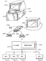
格闘ゲームを楽しむことができる画像生成システムを例にとれば、図1に示すようにプレーヤは、ゲームコントローラ10(広義には操作手段。以下の説明でも同様)を用いてオブジェクトOB1(自キャラクタ)を操作する。そして、相手プレーヤやコンピュータが操作するオブジェクトOB2(敵キャラクタ)と対戦することでゲームを楽しむ。
【0004】
この場合、ゲームコントローラ10は、方向指示キー12と操作ボタン14、16、18、20を備えている。そして、方向指示キー12の右部分を押すとオブジェクトOB1は右方向に移動し、左部分を押すと左方向に移動する。また、操作ボタン14、16、18、20を押すと、各々、右パンチ、左パンチ、右キック、左キックをオブジェクトOB1が繰り出す。
【0005】
このような操作方法は、オブジェクトOB1、OB2(自キャラクタ、敵キャラクタ)が一対一で対戦する格闘ゲームには有効である。
【0006】
しかしながら、図1に示すような操作方法は、オブジェクトOB1が多数のオブジェクトOB2と対戦するようなタイプの格闘ゲーム(多人数格闘ゲーム)には不向きであり、プレーヤ(広義には操作者。以下の説明でも同様)にとって最適な操作環境(インターフェース環境)を提供できないという技術的課題がある。
【0007】
本発明は、以上のような課題に鑑みてなされたものであり、その目的とするところは、好適な操作環境を提供できる画像生成システム、プログラム及び情報記憶媒体を提供することにある。
【0008】
【課題を解決するための手段】
上記課題を解決するために、本発明は、画像生成を行う画像生成システムであって、任意の方向に傾斜させて倒すことが可能であり傾斜角度の検出が可能な第1の操作レバーからの操作データに基づいて、第1のオブジェクトにモーションを行わせる手段と、任意の方向に傾斜させて倒すことが可能であり傾斜角度の検出が可能な第2の操作レバーからの操作データに基づいて、第1のオブジェクトを移動させる手段と、第1のオブジェクトの画像を含む画像を生成する手段とを含み、第1の操作レバーが所与の傾斜角度だけ倒された場合に、第1の操作レバーの倒し方向に対応する攻撃方向に向かって、第1のオブジェクトに攻撃モーションを行わせることを特徴とする。また本発明に係るプログラムは、上記手段としてコンピュータを機能させることを特徴とする。また本発明に係る情報記憶媒体は、コンピュータ読み取り可能な情報記憶媒体であって、上記手段としてコンピュータを機能させるためのプログラムを記憶(記録)したことを特徴とする。
【0009】
本発明によれば、第2の操作レバーが操作されて倒されると、例えばその倒し方向に対応する移動方向に向かって、第1のオブジェクトが移動する。一方、第1の操作レバーが操作されて所与の傾斜角度だけ倒されると、その倒し方向に対応する攻撃方向に向かって、第1のオブジェクトが攻撃モーション(パーツオブジェクト等を攻撃方向に向かって繰り出すモーション等)を行う。
【0010】
このように本発明によれば、第1の操作レバーを所与の傾斜角度だけ倒すだけで、その倒し方向に対応する攻撃方向に向かって、第1のオブジェクトが攻撃モーションを行うようになる。従って、プレーヤが直感的に理解しやすい簡素な操作環境を実現できる。
【0011】
また、プレーヤ(操作者)は、第2の操作レバーで第1のオブジェクトを移動させながら、第2の操作レバーで第1のオブジェクトにモーションを行わせることが可能になり、好適な操作環境をプレーヤに提供できる。
【0012】
なお、第1の操作レバーの所与の傾斜角度β1は、最大傾斜角度をβMAX、傾斜角度の精度をβAC=βMAX/Nとした場合に、例えばβ1=βAC×K(K<N)と表すことができる。
【0013】
また本発明に係る画像生成システム、プログラム及び情報記憶媒体は、第1、第2のオブジェクト間の距離、及び、第1のオブジェクトの向く方向と第2のオブジェクトの存在方向とのなす角度の少なくとも一方に応じて、第1のオブジェクトの攻撃モーションを変化させることを特徴とする。
【0014】
また本発明に係る画像生成システム、プログラム及び情報記憶媒体は、第1の操作レバーの倒し方向により決められる所与の方向範囲に第2のオブジェクトが存在する場合に、該第2のオブジェクトに攻撃を加える攻撃モーションを第1のオブジェクトに行わせることを特徴とする。
【0015】
また本発明に係る画像生成システム、プログラム及び情報記憶媒体は、第1の操作レバーが中立状態から所与の傾斜角度だけ倒されるまでの第1の時間、及び、第1の操作レバーが所与の傾斜角度だけ倒された状態から反力により中立状態に戻るまでの第2の時間の少なくとも一方に応じて、第1のオブジェクトの攻撃モーションを変化させることを特徴とする。
【0016】
また本発明に係る画像生成システム、プログラム及び情報記憶媒体は、第1の操作レバーが第1の傾斜角度だけ倒された場合に、第1のオブジェクトに攻撃モーションを開始させ、その後に第1の操作レバーが第1の傾斜角度よりも大きい第2の傾斜角度だけ倒された場合に、第1のオブジェクトが攻撃モーションを行う方向を確定することを特徴とする。
【0017】
また本発明は、画像生成を行う画像生成システムであって、任意の方向に傾斜させて倒すことが可能であり傾斜角度の検出が可能な第1の操作レバーからの操作データに基づいて、第1のオブジェクトにモーションを行わせる手段と、第1のオブジェクトの画像を含む画像を生成する手段とを含み、第1、第2のオブジェクト間の距離、及び、第1のオブジェクトの向く方向と第2のオブジェクトの存在方向とのなす角度の少なくとも一方に応じて、第1のオブジェクトのモーションを変化させることを特徴とする。また本発明に係るプログラムは、上記手段としてコンピュータを機能させることを特徴とする。また本発明に係る情報記憶媒体は、コンピュータ読み取り可能な情報記憶媒体であって、上記手段としてコンピュータを機能させるためのプログラムを記憶(記録)したことを特徴とする。
【0018】
本発明によれば、第1、第2のオブジェクト間の距離や、第1のオブジェクトの向く方向(例えば正面方向)と第2のオブジェクトの存在方向(例えば第1、第2のオブジェクト間を結ぶ方向、倒し方向又はアクション方向等)とのなす角度に応じて、第1のオブジェクトのモーションが多様に変化するようになる。従って、簡素な操作で多様なモーション表現を実現できる。
【0019】
また本発明は、画像生成を行う画像生成システムであって、任意の方向に傾斜させて倒すことが可能であり傾斜角度の検出が可能な第1の操作レバーからの操作データに基づいて、第1のオブジェクトにモーションを行わせる手段と、第1のオブジェクトの画像を含む画像を生成する手段とを含み、第1の操作レバーの倒し方向により決められる所与の方向範囲に第2のオブジェクトが存在する場合に、該第2のオブジェクトにアクションを加えるモーションを第1のオブジェクトに行わせることを特徴とする。また本発明に係るプログラムは、上記手段としてコンピュータを機能させることを特徴とする。また本発明に係る情報記憶媒体は、コンピュータ読み取り可能な情報記憶媒体であって、上記手段としてコンピュータを機能させるためのプログラムを記憶(記録)したことを特徴とする。
【0020】
本発明によれば、第1の操作レバーの倒し方向に対応するアクション方向(攻撃方向等)と、第2のオブジェクトの存在方向とが完全に一致していない場合にも、第2のオブジェクトにアクションを加えるモーションを第1のオブジェクトに行わせることが可能になり、第1のオブジェクトのモーションを簡素な処理で決定できるようになる。
【0021】
また本発明に係る画像生成システム、プログラム及び情報記憶媒体は、第1の操作レバーの倒し方向により決められる所与の方向範囲に第2のオブジェクトが存在しない場合には、第1のオブジェクトの向く方向と第1の操作レバーの倒し方向とのなす角度に応じたモーションを、第1のオブジェクトに行わせることを特徴とする。
【0022】
このようにすれば、アクションの失敗を表す第1のオブジェクトのモーションについても、リアルに表現できるようになる。
【0023】
また本発明は、画像生成を行う画像生成システムであって、任意の方向に傾斜させて倒すことが可能であり傾斜角度の検出が可能な第1の操作レバーからの操作データに基づいて、第1のオブジェクトにモーションを行わせる手段と、第1のオブジェクトの画像を含む画像を生成する手段とを含み、第1の操作レバーが中立状態から所与の傾斜角度だけ倒されるまでの第1の時間、及び、第1の操作レバーが所与の傾斜角度だけ倒された状態から反力により中立状態に戻るまでの第2の時間の少なくとも一方に応じて、第1のオブジェクトのモーションを変化させることを特徴とする。また本発明に係るプログラムは、上記手段としてコンピュータを機能させることを特徴とする。また本発明に係る情報記憶媒体は、コンピュータ読み取り可能な情報記憶媒体であって、上記手段としてコンピュータを機能させるためのプログラムを記憶(記録)したことを特徴とする。
【0024】
本発明によれば、第1の操作レバーの倒し時間(倒す速さ)や戻し時間(戻す速さ)に応じて、第1のオブジェクトのモーションが変化するようになる。従って、プレーヤが不自然さを感じない操作環境で、第1のオブジェクトの多様なモーション表現を実現できる。
【0025】
また本発明に係る画像生成システム、プログラム及び情報記憶媒体は、前記第1、第2の時間の総和時間に応じて、第1のオブジェクトのモーションを変化させることを特徴とする。
【0026】
このようにすれば、クイックな操作環境を実現しながら、時間計測の不確定要素を低減できるようになる。
【0027】
また本発明に係る画像生成システム、プログラム及び情報記憶媒体は、第1の操作レバーが所与の傾斜角度だけ倒された場合に、第1のオブジェクトに第1のモーションを開始させ、第1の時間、第2の時間又は第1、第2の時間の総和時間が所与の時間よりも短い場合には、第1のオブジェクトに第1のモーションを継続して行わせ、第1の時間、第2の時間又は第1、第2の時間の総和時間が所与の時間よりも長い場合には、第1のオブジェクトに第2のモーションを行わせることを特徴とする。
【0028】
このようにすれば、第1の操作レバーが所与の傾斜角度だけ倒された時点で、第1のモーションが開始するようになるため、クイックな操作環境を実現できる。また、第1の時間、第2の時間又は総和時間に応じて、第1、第2のモーションのいずれを行うかが決定されるようになるため、時間計測の不確定要素を低減しながら多様なモーション表現を実現できる。
【0029】
また本発明は、画像生成を行う画像生成システムであって、任意の方向に傾斜させて倒すことが可能であり傾斜角度の検出が可能な第1の操作レバーからの操作データに基づいて、第1のオブジェクトにモーションを行わせる手段と、第1のオブジェクトの画像を含む画像を生成する手段とを含み、第1の操作レバーが第1の傾斜角度だけ倒された場合に、第1のオブジェクトにモーションを開始させ、その後に第1の操作レバーが第1の傾斜角度よりも大きい第2の傾斜角度だけ倒された場合に、第1のオブジェクトがモーションを行う方向を確定することを特徴とする。また本発明に係るプログラムは、上記手段としてコンピュータを機能させることを特徴とする。また本発明に係る情報記憶媒体は、コンピュータ読み取り可能な情報記憶媒体であって、上記手段としてコンピュータを機能させるためのプログラムを記憶(記録)したことを特徴とする。
【0030】
本発明によれば、第1の操作レバーが第1の傾斜角度だけ倒されると、第1のオブジェクトのモーションがとりあえず開始するようになるため、クイックな操作環境を実現できる。そして、それに引き続いて第1の操作レバーが更に第2の傾斜角度だけ倒されると、第1のオブジェクトがモーションを行う方向(モーション方向、アクション方向、攻撃方向)が確定する。従って、第1の操作レバーの操作方向が蛇行したような場合にも、プレーヤの意図する方向に向かって、第1のオブジェクトにモーションを行わせることが可能になる。
【0031】
また本発明に係る画像生成システム、プログラム及び情報記憶媒体は、第1の操作レバーが第1の傾斜角度よりも大きい第2の傾斜角度だけ倒された場合に、第1の操作レバーの倒し方向に対応する方向に、第1のオブジェクトの向きを向ける補正を行うことを特徴とする。
【0032】
このようにすれば、第1のオブジェクトがモーションを行いながら、その向きが変わるようになり、プレーヤが違和感を感じにくいモーション表現を実現できる。
【0033】
また本発明に係る画像生成システム、プログラム及び情報記憶媒体は、任意の方向に傾斜させて倒すことが可能であり傾斜角度の検出が可能な第2の操作レバーからの操作データに基づいて、第1のオブジェクトを移動させることを特徴とする。
【0034】
このようにすれば、第1の操作レバーで第1のオブジェクトのモーションを制御しながら、第2の操作レバーで第1のオブジェクトの移動を制御できるようになり、好適な操作環境を提供できる。
【0035】
【発明の実施の形態】
以下、本実施形態について図面を用いて説明する。
【0036】
なお、以下に説明する本実施形態は、特許請求の範囲に記載された本発明の内容を何ら限定するものではない。また本実施形態で説明される構成の全てが本発明の解決手段として必須であるとは限らない。
【0037】
1.構成
図2に、本実施形態の画像生成システム(ゲームシステム)の機能ブロック図の一例を示す。なお同図において本実施形態は、少なくとも処理部100を含めばよく(或いは処理部100と記憶部170を含めばよく)、それ以外のブロックについては任意の構成要素とすることができる。
【0038】
操作部160は、プレーヤが操作データを入力するためのものであり、その機能は、レバー、ボタン、マイク、或いは筺体などのハードウェアにより実現できる。
【0039】
記憶部170は、処理部100や通信部196などのワーク領域となるもので、その機能はRAMなどのハードウェアにより実現できる。
【0040】
情報記憶媒体180(コンピュータにより読み取り可能な媒体)は、プログラムやデータなどを格納するものであり、その機能は、光ディスク(CD、DVD)、光磁気ディスク(MO)、磁気ディスク、ハードディスク、磁気テープ、或いはメモリ(ROM)などのハードウェアにより実現できる。処理部100は、この情報記憶媒体180に格納されるプログラム(データ)に基づいて本発明(本実施形態)の種々の処理を行う。即ち情報記憶媒体180には、本発明(本実施形態)の各手段(特に処理部100に含まれるブロック)としてコンピュータを機能させる(各手段をコンピュータに実現させる)ためのプログラムが記憶(記録、格納)され、このプログラムは、例えば1又は複数のモジュール(オブジェクト指向におけるオブジェクトも含む)を含む。
【0041】
なお、情報記憶媒体180に格納される情報の一部又は全部は、システムへの電源投入時等に記憶部170に転送されることになる。また情報記憶媒体180には、本発明の処理を行うためのプログラム、画像データ、音データ、表示物の形状データ、本発明の処理を指示するための情報、或いはその指示に従って処理を行うための情報などを含ませることができる。
【0042】
表示部190は、本実施形態により生成された画像を出力するものであり、その機能は、CRT、LCD、或いはHMD(ヘッドマウントディスプレイ)などのハードウェアにより実現できる。
【0043】
音出力部192は、本実施形態により生成された音を出力するものであり、その機能は、スピーカなどのハードウェアにより実現できる。
【0044】
携帯型情報記憶装置194は、プレーヤの個人データやゲームのセーブデータなどが記憶されるものであり、この携帯型情報記憶装置194としては、メモリカードや携帯型ゲーム装置などを考えることができる。
【0045】
通信部196は、外部(例えばホスト装置や他の画像生成システム)との間で通信を行うための各種の制御を行うものであり、その機能は、各種プロセッサ、或いは通信用ASICなどのハードウェアや、プログラムなどにより実現できる。
【0046】
なお本発明(本実施形態)の各手段としてコンピュータを機能させるためのプログラム(データ)は、ホスト装置(サーバー)が有する情報記憶媒体からネットワーク及び通信部196を介して情報記憶媒体180に配信するようにしてもよい。このようなホスト装置(サーバー)の情報記憶媒体の使用も本発明の範囲内に含まれる。
【0047】
処理部100(プロセッサ)は、操作部160からの操作データやプログラムなどに基づいて、ゲーム処理、画像生成処理、或いは音生成処理などの各種の処理を行う。この場合、処理部100は、記憶部170内の主記憶部172をワーク領域として使用して、各種の処理を行う。
【0048】
ここで、処理部100が行う処理としては、コイン(代価)の受け付け処理、各種モードの設定処理、ゲームの進行処理、選択画面の設定処理、オブジェクト(1又は複数のプリミティブ)の位置や回転角度(X、Y又はZ軸回り回転角度)を求める処理、オブジェクトを動作させる処理(モーション処理)、視点の位置(仮想カメラの位置)や視線角度(仮想カメラの回転角度)を求める処理、マップオブジェクトなどのオブジェクトをオブジェクト空間へ配置する処理、ヒットチェック処理、ゲーム結果(成果、成績)を演算する処理、複数のプレーヤが共通のゲーム空間でプレイするための処理、或いはゲームオーバー処理などを考えることができる。
【0049】
処理部100は、移動処理部110、モーション処理部112、画像生成部120、音生成部130を含む。なお、処理部100は、これらの全ての機能ブロックを含む必要はない。
【0050】
ここで、移動処理部110は、オブジェクト(キャラクタ、ロボット、車又は戦車等の移動オブジェクト)の移動を制御する処理を行うものである。
【0051】
より具体的には、移動処理部110は、オブジェクトをオブジェクト空間(ゲーム空間)で移動(並進移動、回転移動)させる処理を行う。そして、このオブジェクトの移動処理は、操作部160からの操作データ(プレーヤからの入力データ)や前のフレーム(1/60秒、1/30秒等)でのオブジェクトの位置、回転角度(方向)等に基づいて、現在のフレーム(インター)でのオブジェクトの位置、回転角度を求めることで実現できる。例えば(k−1)フレームでのオブジェクトの位置、回転角度をPk-1、θk-1とし、オブジェクトの1フレームでの位置変化量(速度)、回転変化量(回転速度)を△P、△θとする。するとkフレームでのオブジェクトの位置Pk、回転角度θkは例えば下式(1)、(2)のように求められる。
【0052】
Pk=Pk-1+△P (1)
θk=θk-1+△θ (2)
モーション処理部112は、オブジェクトにモーション(アニメーション)を行わせる処理(モーション再生、モーション生成)を行う。そして、このオブジェクトのモーション処理は、オブジェクト(キャラクタ)のモーションを、モーションデータ記憶部176に記憶されているモーションデータに基づいて再生することで実現できる。
【0053】
より具体的には、モーションデータ記憶部176には、オブジェクト(スケルトン)を構成する各パーツオブジェクト(スケルトンを構成するモーション骨)の位置又は回転角度等を含むモーションデータが記憶されている。モーション処理部112は、このモーションデータを読み出し、このモーションデータに基づいてオブジェクトの各パーツオブジェクト(モーション骨)を動かすことで(オブジェクトのスケルトン形状を変形させることで)、オブジェクトのモーションを再生する。
【0054】
なお、モーションデータ記憶部176に記憶されるモーションデータは、現実世界の人にセンサをつけてモーションキャプチャを行うことで作成したものであることが望ましいが、モーションデータを、物理シミュレーション(物理計算を利用したシミュレーション。物理計算は擬似的な物理計算でもよい)などによりリアルタイムに生成するようにしてもよい。
【0055】
また、少ないモーションデータ量でリアルなモーションを再生するために、モーション補間やインバース・キネマティクスを用いてモーション再生を行うことが望ましい。
【0056】
さて本実施形態では、操作部160が、アナログレバーAL1、AL2(広義には、任意の方向に傾斜させて倒すことが可能であり、倒した時の傾斜角度の検出が可能な第1、第2の操作レバー。以下の説明でも同様)を含む。
【0057】
そして移動処理部110は、アナログレバーAL2(第2の操作レバー)からの操作データ(例えば第1、第2の軸方向のボリューム値)に基づいて、オブジェクト(キャラクタ)を移動させる処理を行う。
【0058】
より具体的には、アナログレバーAL2(第2の操作レバー)の倒し方向(傾斜動作を行う方向)に対応する移動方向(任意の倒し方向に一対一に対応する移動方向)に向かってオブジェクトを移動させる。この場合、アナログレバーAL2の傾斜角度に応じてオブジェクトの移動速度を変化させてもよい。また、アナログレバーAL2によりオブジェクトが移動する際には、移動速度等に応じた移動モーション(歩くモーション又は走るモーション等)をオブジェクトに行わせることが望ましい。
【0059】
またモーション処理部112は、アナログレバーAL1(第1の操作レバー)からの操作データ(例えば第1、第2の軸方向のボリューム値)に基づいて、オブジェクト(キャラクタ)にモーションを行わせる処理(モーション再生、モーション生成)を行う。
【0060】
より具体的には、アナログレバーAL1の倒し方向(傾斜動作を行う方向)に対応するアクション方向(任意の倒し方向に一対一に対応するアクション方向であり、攻撃方向、ガード方向、ボールをヒットする方向、ボールをキャッチする方向、又はアイテムを取得する方向等)に向かって、オブジェクトにモーション(アクションモーション)を行わせる。即ち、そのアクション方向に向かって、オブジェクトのパーツオブジェクト(手足等のオブジェクト)を動かしたり、オブジェクトの代表点の位置が移動するモーションを、オブジェクトに行わせる。
【0061】
そして更に本実施形態では、オブジェクト(第1、第2のオブジェクト)間の距離関係、オブジェクト間の方向関係、アナログレバーAL1の倒し時間(所与の傾斜角度だけ倒されるまでの時間、倒す速さ)、又は反力によるAL1の戻り時間(所与の傾斜角度から中立状態に戻るまでの時間、戻る速さ)等に応じて、オブジェクトのモーションを変化させている(モーションを異ならせている)。
【0062】
また本実施形態では、アナログレバーAL1の倒し方向により決められる方向範囲(予め分割された複数の方向範囲の中から、倒し方向に応じて選択された方向範囲)に、アクションの対象となる他のオブジェクト(第2のオブジェクト)が存在するか否かを判定する。そして、存在する場合に、その他のオブジェクトにアクションを与えるアクションモーションをオブジェクト(第1のオブジェクト)に行わせるようにしている。
【0063】
また本実施形態では、アナログレバーAL1が傾斜角度β1(例えば遊び確保のための傾斜角度)だけ倒された場合に、オブジェクトのモーションを、とりあえず開始する(モーション再生をスタートする)。そして、例えば所定期間内にアナログレバーAL1が更に倒され、その傾斜角度β2(β2>β1)になった場合に、オブジェクトのモーション方向(アクションを行う方向)を確定するようにしている。
【0064】
画像生成部120は、処理部100で行われる種々の処理の結果に基づいて画像処理を行い、ゲーム画像を生成し、表示部190に出力する。例えば、いわゆる3次元のゲーム画像を生成する場合には、まず、座標変換、クリッピング処理、透視変換、或いは光源計算等のジオメトリ処理が行われ、その処理結果に基づいて、描画データ(プリミティブ面の頂点(構成点)に付与される位置座標、テクスチャ座標、色(輝度)データ、法線ベクトル或いはα値等)が作成される。そして、この描画データ(プリミティブ面データ)に基づいて、ジオメトリ処理後のオブジェクト(1又は複数プリミティブ面)の画像が、描画バッファ174(フレームバッファ、ワークバッファ等のピクセル単位で画像情報を記憶できるバッファ)に描画される。これにより、オブジェクト空間内において仮想カメラ(所与の視点)から見える画像が生成されるようになる。
【0065】
音生成部130は、処理部100で行われる種々の処理の結果に基づいて音処理を行い、BGM、効果音、又は音声などのゲーム音を生成し、音出力部192に出力する。
【0066】
なお、本実施形態の画像生成システムは、1人のプレーヤのみがプレイできるシングルプレーヤモード専用のシステムにしてもよいし、このようなシングルプレーヤモードのみならず、複数のプレーヤがプレイできるマルチプレーヤモードも備えるシステムにしてもよい。
【0067】
また複数のプレーヤがプレイする場合に、これらの複数のプレーヤに提供するゲーム画像やゲーム音を、1つの端末を用いて生成してもよいし、ネットワーク(伝送ライン、通信回線)などで接続された複数の端末(ゲーム機、携帯電話)を用いて生成してもよい。
【0068】
2.本実施形態の特徴
次に本実施形態の特徴について図面を用いて説明する。なお、以下では、格闘ゲームに本実施形態を適用した場合を主に例にとり説明するが、本実施形態は、格闘ゲーム以外の他のゲームにも広く適用できる。
【0069】
2.1 アナログレバーによる攻撃モーション
図3(A)に、本実施形態で使用されるゲームコントローラ30(広義には操作手段。以下の説明でも同様)の例を示す。このゲームコントローラ30は、方向指示キー32(十字キー)、操作ボタン34、36、38、40の他に、アナログレバーAL1、AL2(第1、第2の操作レバー)を備えている。
【0070】
このアナログレバーAL1、AL2(アナログスティック、アナログ方向キー)は、図3(A)に示すように任意の方向(0度〜360度の方向)に傾斜させて倒すことが可能であり、倒した時の傾斜角度の検出が可能な操作レバーである。即ち、通常のデジタル式(2値式)の操作レバーでは、レバーが中立状態の時の値及びレバーを倒した時の値というように2値の値しか検出できない。これに対してアナログレバーAL1、AL2では、多値(3値以上)の傾斜角度を検出できる。例えば最大傾斜角度をβMAXとした場合に、βMAX/N(N≧3)の精度で傾斜角度を検出できる。
【0071】
より具体的には図3(B)に示すように、このアナログレバーAL(AL1又はAL2。以下の説明でも同様)では、レバーの傾斜角度βと、レバーの倒し方向TD(例えばX軸とのなす角度α)が検出可能になっている。
【0072】
即ち、アナログレバーALには、X軸(広義には第1の軸。以下の説明でも同様)方向のボリューム値XVLを検出する図示しない第1の検出装置と、Z軸(広義には第2の軸。以下の説明でも同様)方向のボリューム値ZVLを検出する図示しない第2の検出装置が備え付けられている。これらのボリューム値XVL、ZVL(例えば0〜255の値)は、各々、Z軸周りの回転角度、X軸周りの回転角度に相当する。
【0073】
そして図3(C)に示すように、これらの第1、第2の検出装置で検出されたボリューム値XVL、ZVL(操作ベクトルの第1、第2の座標成分)に基づいて、アナログレバーALの傾斜角度βに相当する距離D=(XVL2+ZVL2)1/2(操作ベクトルの長さ)が計算される。また、これらのXVL、ZVLに基づいて、アナログレバーALの倒し方向TD(操作ベクトルの方向)に相当する角度α=tan-1(ZVL/XVL)が計算される。
【0074】
そして、本実施形態ではこのようにして計算された傾斜角度β(距離D)、倒し方向TD(角度α)に基づいて、オブジェクトの移動処理やモーション処理を行っている。
【0075】
具体的には図4(A)に示すように、アナログレバーAL2(第2の操作レバー)を倒すと、その倒し方向が検出され、その倒し方向に対応する移動方向に、オブジェクトOB1(操作対象となる第1のオブジェクト。自キャラクタ)が移動する。例えばアナログレバーAL2を前後左右に倒すと、オブジェクトOB1もオブジェクト空間内で前後左右に動く。そして、この場合、アナログレバーAL2は任意の方向(0度〜360度)に倒すことができるため、オブジェクトOB1も任意の移動方向(0度〜360度)に移動できる。更に、アナログレバーAL2の傾斜角度βに基づいて、オブジェクトOB1の移動速度等を変化させることも可能になる。
【0076】
一方、図4(B)、(C)に示すように、アナログレバーAL1を所与の傾斜角度(例えば0度〜10度の範囲内の微少角度)だけ倒すと、その倒し方向TDが検出され、その倒し方向TDに対応する攻撃方向AD(広義にはアクション方向。以下の説明でも同様)に向かって、オブジェクトOB1が攻撃モーション(広義にはモーション或いはアクションモーション。以下の説明でも同様)を行う。
【0077】
例えば図4(B)では、アナログレバーAL1が右前方向に倒されたため、オブジェクトOB1が右前方向に向かって攻撃モーションを行う。これにより、右前方向に存在するオブジェクトOB2-1(アクション対象となる第2のオブジェクト)に攻撃がヒットしている。
【0078】
一方、図4(C)では、アナログレバーAL1が左後ろ方向に倒されたため、オブジェクトOB1は左後ろ方向に向かって攻撃モーションを行う。これにより、左後ろ方向に存在するオブジェクトOB2-2に攻撃がヒットしている。
【0079】
このように本実施形態では、アナログレバーAL2からの操作データに基づいてオブジェクトOB1の移動処理を行い、アナログレバーAL1からの操作データに基づいてオブジェクトOB2のモーション処理を行っている。従って、図1で説明した従来の操作方法に比べて、好適な操作環境をプレーヤに提供できる。
【0080】
即ち図1の操作方法ではプレーヤは、オブジェクトOB1(自キャラクタ)の攻撃方向を明示的に指定することができない。このため、プレーヤにとって直感的に理解しにくい操作環境(インターフェース環境)になっていた。
【0081】
これに対して図4(A)、(B)、(C)の本実施形態の操作方法では、アナログレバーAL1の倒し方向によって、オブジェクトOB1の攻撃方向AD(モーション方向)を明示的に指定できる。従って、プレーヤにとって直感的に理解しやすい操作環境を提供できる。
【0082】
また図1の操作方法では、攻撃する毎に、オブジェクトOB1の向きをオブジェクトOB2の方に向くように修正してから、攻撃する必要があった。例えばオブジェクトOB1がOB2の後ろに回り込んだ場合には、OB1の向きを右向きから左向きに修正してから、OB2に対して攻撃を行う必要があった。
【0083】
これに対して本実施形態の操作方法では、オブジェクトOB1の移動動作と攻撃動作を同時に実現することが可能になる。即ち、攻撃する毎にオブジェクトOB1の向きを修正することなく、1アクションで全方向に対して攻撃を行うことが可能になり、操作方法の簡素化を図れる。
【0084】
例えば図4(B)では、オブジェクトOB1の向きを修正することなく、アナログレバーAL1を右前方向に倒すだけという1アクションで、オブジェクトOB2-1に対して攻撃を加えることができる。同様に図4(C)でも、アナログレバーAL1を左後ろ方向に倒すだけという1アクションで、OB2-2に対して攻撃を加えることができる。
【0085】
また図1の操作方法では、攻撃方向を明示的に指定できないため、オブジェクトOB1が多数のオブジェクトOB2と対戦するようなタイプのゲーム(多人数格闘ゲーム)には不向きであった。
【0086】
これに対して本実施形態の操作方法では、簡素な方法で任意の方向に攻撃を行うことができるため、OB1が多数のOB2と対戦するようなタイプのゲームに好適な操作環境を提供できる。即ち図4(A)、(B)、(C)に示すように、プレーヤが操作するオブジェクトOB1が多数の敵オブジェクトOB2と対戦するようなゲームを実現でき、プレーヤの仮想現実感を増すことができる。
【0087】
更に本実施形態では、アナログレバーAL1、AL2の方向入力の正確さでゲーム技量を競い合うことが可能になり、プレーヤにとって理解しやすい操作環境を提供できる。
【0088】
なお、図4(B)、(C)に示すように、オブジェクトOB1の攻撃方向AD(モーション方向)を表すための表示を行うことが望ましい。即ち、オブジェクトOB1の位置から攻撃方向AD(敵オブジェクトの存在方向)に向かって延びる矢印AHを表示する。このようにすることで、プレーヤは、自分自身がどの方向に向かって攻撃したかを、即座に且つ直感的に認識できるようになる。
【0089】
なお、アナログレバーAL1の傾斜角度に応じて矢印AHを連続的に伸長させてもよい。
【0090】
また、アナログレバーAL1の傾斜角度が一定角度になり、入力が成立したと判定された場合に、矢印AHの画像(デザイン)を変更して、入力の成立をプレーヤに伝えるようにしてもよい。
【0091】
また、プレーヤがアナログレバーAL1を複数の方向に連続的に倒した場合には、入力が成立した全ての方向に矢印AHを残すようにしてもよい。
【0092】
更に、オブジェクトOB1の攻撃モーションの再生が間に合わない場合や、OB1がダメージを受けている場合など、攻撃の入力が行えない場合に、矢印AHを非表示にして、入力不可であることをプレーヤに伝えるようにしてもよい。
【0093】
2.2 距離関係、方向関係に応じた攻撃モーションの変化
本実施形態ではオブジェクトOB1、OB2間の距離関係及び方向関係の少なくとも一方に応じてOB1の攻撃モーション(モーション)を変化させている。
【0094】
即ち図5(A)に示すように、オブジェクトOB1、OB2間の距離Rや、OB1の向く方向FD(正面方向、目鼻が向く方向)とOB2の存在方向(OB1、OB2間を結ぶ方向OBD、アナログレバーの倒し方向TD又はTDに対応する攻撃方向AD)とのなす角度γに応じて、OB1の攻撃モーションを変化させる。
【0095】
例えばオブジェクトOB2がOB1の右方向に存在する場合(γ=90度)には、図5(B)に示すように攻撃モーションを変化させる。即ち、距離Rが近距離の場合は右パンチ、中距離の場合は右キック、遠距離の場合は右跳び蹴りの攻撃モーションをOB1に行わせる。
【0096】
またオブジェクトOB2がOB1の左方向に存在する場合(γ=−90度)には、例えば図5(C)に示すように攻撃モーションを変化させる。即ち、距離Rが近距離の場合は左フック、中距離の場合は左後ろ回し蹴り、遠距離の場合は左ステップキックの攻撃モーションをOB1に行わせる。
【0097】
このようにすれば、距離Rや角度γに応じてオブジェクトOB1の攻撃モーションが多様に変化するようになるため、ゲーム演出効果が高くリアルな画像を簡素な処理で生成できる。
【0098】
即ち図1の操作方法では、操作ボタン14、16、18、20を単に押すだけでは、右パンチ、左パンチ、右キック、左キックなどの標準的な攻撃モーションしか表現できない。このため、これらの標準的な攻撃モーション以外の特殊な攻撃モーションをオブジェクトOB1に行わせるためには、複数のボタン操作の組み合わせや操作ボタンと方向指示キーの操作の組み合わせである特殊操作をプレーヤが行う必要がある。例えば、操作ボタン14、16を同時に押したり、方向指示キー12の右部分を押しながら操作ボタン18を押すなどの特殊操作が必要になる。
【0099】
しかしながら、このような特殊操作は、オブジェクトOB1の実際の動きとは対応していないため、プレーヤにとって直感的に理解しにくい操作となっていた。また、プレーヤは、オブジェクト毎に設定された複雑な特殊操作をマスターしなければならないため、ゲーム操作が難しく、初心者にゲームプレイを敬遠される要因となっていた。
【0100】
これに対して本実施形態によれば、距離Rや角度γに応じた最適な攻撃モーションをオブジェクトOB1に行わせることができる。従って、プレーヤにとって直感的に理解しやすい操作環境を実現できる。また、アナログレバーAL1の倒し方向に応じて決められる角度γや、敵であるOB2との距離Rに応じて、OB1の攻撃モーションが自動的に決定されるようになる。従って、プレーヤが特殊操作を取得しなくても、OB1の多様な攻撃モーションを実現でき、簡素な操作環境でリアルな画像を生成できるようになる。
【0101】
なお、距離Rや角度γと数学的に等価なパラメータを用いてオブジェクトOB1のモーションを変化させる場合も本発明の均等範囲に含まれる。
【0102】
図6(A)〜図9に本実施形態により生成されるゲーム画像の例を示す。
【0103】
図6(A)は、オブジェクトOB1が基本姿勢で立っている時のゲーム画像の例である。図6(A)でオブジェクトの目鼻が向く方向(地面に表示される矢印の方向)が、オブジェクトの向く方向(図5(A)のFD)になる。
【0104】
図6(B)は、アナログレバーが倒されて、オブジェクトOB1の前方向にいる敵(オブジェクトOB2)にOB1が攻撃を加えている時のゲーム画像の例である。このように本実施形態では、敵の存在方向に対応する倒し方向にアナログレバーを微少な傾斜角度(β1)だけ倒すだけで、オブジェクトOB1が敵に対する攻撃モーションを行うようになる。従って、プレーヤが所望する攻撃をアナログレバーを倒すだけという1つのアクションで実現できるようになり、プレーヤが直感的に理解しやすい操作環境を提供できる。
【0105】
図7(A)は、アナログレバーが倒されて、左方向にいる敵にOB1が攻撃を加えている時のゲーム画像の例であり、図7(B)は、後ろ方向にいる敵にOB1が攻撃を加えている時のゲーム画像の例である。
【0106】
図6(B)、図7(A)、(B)を比較すれば明らかなように、本実施形態では、敵との方向関係に応じてオブジェクトOB1の攻撃モーションが多様に変化する。即ち、プレーヤが複雑な特殊操作を行わなくても、敵との方向関係に応じてOB1の攻撃モーションが自動的に変化するようになり、簡素な操作環境で多様な画像表現を実現できる。
【0107】
図8(A)は、オブジェクトOB1と敵(オブジェクトOB2)との距離Rが近距離の場合のゲーム画像の例である。同様に図8(B)、図9は、敵との距離Rが中距離、遠距離の場合のゲーム画像の例である。
【0108】
図8(A)、(B)、図9を比較すれば明らかなように、本実施形態では、敵との距離関係に応じてオブジェクトOB1の攻撃モーションが変化する。即ち、プレーヤが複雑な特殊操作を行わなくても、敵との距離関係に応じてOB1の攻撃モーションが自動的に変化するようになり、簡素な操作環境で多様な画像表現を実現できる。
【0109】
2.3 方向範囲の判定
本実施形態ではオブジェクトOB2が存在する方向範囲を判定して、オブジェクトOB1に攻撃モーションを行わせている。
【0110】
より具体的には図10(A)では、アナログレバー(AL1)の倒し方向TDにより決められる方向範囲DRに、敵オブジェクトOB2-1、OB2-2が存在する。従って、この場合には、オブジェクトOB2-1又はOB2-2に攻撃(アクション)を加えるモーションをOB1に行わせる。なお、OB2-1、OB2-2のいずれに攻撃を加えるかは、OB1からの距離に基づいて決め、距離が近いものを選択してもよい。或いは、倒し方向TDとOB2の存在方向とのずれに基づいて決め、ずれが小さいものを選択するようにしてもよい。
【0111】
一方、図10(B)では、アナログレバーの倒し方向により決められる方向範囲DRに、敵オブジェクトが存在しない。従って、この場合には、攻撃の失敗となり、例えば空振りのモーションをオブジェクトOB1に行わせる。
【0112】
そして、この場合、よりリアルで多様な画像を表現するためには、オブジェクトOB1の向く方向FDとアナログレバーの倒し方向TDとのなす角度γに応じたモーションを、オブジェクトOB1に行わせることが望ましい。
【0113】
このようにすれば、アナログレバーの倒し方向TDに応じてオブジェクトOB1のモーションが多様に変化するようになり、OB1の空振りのモーションが単調になってしまう事態を効果的に防止できる。
【0114】
なお図10(C)に示すように、0度〜360度の範囲を分割した複数の方向範囲DR0〜DR24(広義にはDR0〜DRM)を予め設定しておいてもよい。この場合には、各方向範囲DR0〜DR24に対して攻撃モーション(モーションデータ)を対応づけておく。そして、アナログレバーの倒し方向TDに基づいて、これらの方向範囲DR0〜DR24のいずれかを選択し、選択された方向範囲に対応づけられた攻撃モーションを再生するようにする。
【0115】
このようににすれば、オブジェクトOB1の攻撃モーションを簡素な処理で決定できるようになり、処理負荷を軽減できる。また、方向範囲の数に応じた攻撃モーションを用意するだけで済むため、モーションデータのデータ量を少なくすることができ、メモリの使用記憶容量を節約できる。
【0116】
なお、各方向範囲に対応づけられた攻撃モーションをモーション補間して、オブジェクトOB1の攻撃モーションを決定するようにしてもよい。
【0117】
2.4 アナログレバーの倒し時間、戻り時間に応じたモーション変化
本実施形態では、アナログレバーの倒し時間(倒す速さ)や戻り時間(戻る速さ)に応じて、オブジェクトOB1のモーションを変化させている(モーションを異ならせている)。
【0118】
より具体的には図11(A)に示すように、アナログレバーAL(AL1)が中立(ニュートラル)状態から傾斜角度βだけ倒されるまでの時間T1に応じて、オブジェクトOB1のモーションを変化させたり、ALが傾斜角度βだけ倒された状態からALの反力により中立状態に戻るまでの時間T2に応じて、OB1のモーションを変化させる。なお、アナログレバーALを倒す際のβとALが戻る際のβを異ならせてもよい。
【0119】
このようにすれば、図11(B)に示すように、例えばプレーヤが指などでアナログレバーALをはじく操作(クイック操作)を行った場合に、図12(A)に示すようなジャブモーション(クイックモーション)をオブジェクトOB1に行わせることが可能になる。
【0120】
即ち、図11(B)に示すようにプレーヤがアナログレバーALをはじき操作などで速く操作した場合には、図11(A)の時間T1やT2が短くなる。そして、このように時間T1及びT2の少なくとも一方が短い場合には、図12(A)に示すようなジャブモーション(広義には第1のモーション、モーション再生時間が短いモーション、動作が速いモーション。以下の説明でも同様)をオブジェクトOB1に行わせる。
【0121】
一方、プレーヤがアナログレバーALを通常の速さで操作した場合には、図11(A)の時間T1やT2がはじき操作の場合に比べて長くなる。そして、このように時間T1及びT2の少なくとも一方が長い場合には、図12(B)に示すようなフックモーション(広義には第2のモーション、モーション再生時間が長いモーション、動作が遅いモーション。以下の説明でも同様)をオブジェクトOB1に行わせる。
【0122】
このようにすれば、プレーヤがアナログレバーALを操作する速さを変化させるだけで、オブジェクトOB1のモーションが多様に変化するようになる。従って、プレーヤの操作環境を複雑化することなく、多様でリアルな画像表現を実現できる。
【0123】
なお、オブジェクトOB1のモーションは、時間T1のみに応じて変化させてもよいし、時間T2のみに応じて変化させてもよい。或いは、時間T1とT2の総和時間(T1とT2の両方が影響する時間)に応じて変化させてよい。
【0124】
例えば時間T1に応じてモーションを変化させる第1の手法を採用すれば、アナログレバーALを倒してから直ぐに、倒す速さを検出し、図12(A)に示すようなジャブモーションを再生できるようになる。これにより、操作のクイック感を実現できる。
【0125】
一方、時間T2に応じてモーションを変化させる第2の手法を採用すれば、時間計測の不確定要素を低減できる。即ち、プレーヤが積極的な動作でアナログレバーALを操作した場合には、操作の速さ(時間)にバラツキが生じてしまい、プレーヤがクイック操作をしたか否かの判断が難しくなる。
【0126】
これに対して、時間T2は、アナログレバーALが図示しない弾性体の反力により中立状態に戻るまでの時間であり、プレーヤの操作の速さに依存せずに、ほぼ一定値になる。従って、時間T2にはバラツキが生じにくく、プレーヤがクイック操作(はじき操作)をしたか否かの判断が容易になる。従って、この意味においては、上記の第1の手法よりも第2の手法を採用することが望ましい。
【0127】
そして、第1、第2の手法の両方の利点を活用するには、第1、第2の時間の総和時間(第1、第2の時間の両方が影響する時間)に応じてモーションを変化させる第3の手法を採用することが望ましい。この第3の手法によれば、時間T1を考慮してモーションが変化するため、クイックな操作環境を実現できる。また、時間T2も考慮してモーションが変化するため、時間計測の不確定要素も軽減できるようになる。
【0128】
なお、アナログレバーALが所与の傾斜角度β1だけ倒された場合には、とりあえずオブジェクトOB1にジャブモーション(第1のモーション)を開始させ、その後に、所与の傾斜角度β2(=β)だけALが倒された場合には、その時の時間T1、T2又はT1+T2を判断し、開始したジャブモーションを変化させてもよい。
【0129】
より具体的には、時間T1、T2又はT1+T2が短い場合には、オブジェクトOB1に図12(A)に示すようなジャブモーションを継続して行わせる。
【0130】
一方、時間T1、T2又はT1+T2が長い場合には、オブジェクトOB1に図12(B)に示すようなフックモーション(第2のモーション)を行わせる。この場合に、ジャブモーションからフックモーションへの繋ぎモーションは、モーション補間(スケルトンモデルの関節の位置や骨間のなす角度の補間)により生成することが望ましい。
【0131】
このようにすれば、アナログレバーALを微少な傾斜角度β1だけ倒した時点で、オブジェクトOB1のモーションが開始するようになるため、クイックな操作環境を実現できる。そして、アナログレバーAL2が更に倒された場合に、その倒し速度や戻り速度に応じてオブジェクトOB1のモーションが変化するようになるため、モーション画像の多様化を実現できる。
【0132】
2.5 モーションの開始とモーション方向の確定
さて、アナログレバーALは任意の方向に倒すことができ、プレーヤの操作の自由度が高い。逆に言えば、アナログレバーALを倒す方向は、プレーヤの操作の正確さに応じて様々な方向に変化してしまい、図13(A)、(B)に示すような蛇行操作が行われる場合が多い。
【0133】
このような場合に、プレーヤがアナログレバーALを倒し始めて直ぐの段階で、ALの倒し方向を確定し、オブジェクトOB1がモーションを行う方向(攻撃方向、アクション方向)を確定してしまうと、プレーヤが意図した方向とは違う方向に向かって、OB1がモーションを行う事態が生じてしまう。
【0134】
そこで本実施形態では図13(C)に示すように、アナログレバーAL(AL1)が傾斜角度β1(例えば遊び確保のための微少な角度)だけ倒された段階で、とりあえずオブジェクトのモーションを開始するようにする。そして、この場合にオブジェクトOB1が行うモーションの方向(攻撃方向、アクション方向)は、例えば図13(D)に示すように傾斜角度β1だけアナログレバーALを倒した時の倒し方向TD1(角度α1)に対応する方向に設定する。
【0135】
そして、引き続いて更にアナログレバーALが倒されて、ALの傾斜角度がβ2(β2>β1)になった場合に、オブジェクトOB1がモーションを行う方向を最終的に確定するようにする。例えば、オブジェクトがモーションを行う方向を、図13(D)に示すように傾斜角度β2だけアナログレバーALを倒した時の倒し方向TD2(角度α2)に対応する方向に確定する。
【0136】
このようにすれば、アナログレバーALが少しだけ倒された段階で、とりあえずオブジェクトOB1のモーションが開始するようになるため、クイックな操作環境をプレーヤに提供できる。
【0137】
そして、図13(A)に示すようにプレーヤの操作方向が蛇行しても、図13(B)のE1に示すような最終的な倒し方向(図13(D)のTD2)に対応した方向(攻撃方向、アクション方向)に向かって、オブジェクトOB1にモーションを行わせることができる。従って、プレーヤが実際に意図した方向に向かって、オブジェクトOB1がモーションを行うようになり、プレーヤがより自然に感じる操作環境を提供できる。
【0138】
なお、アナログレバーALが傾斜角度β2だけ倒された場合には、その時のALの倒し方向TD2に対応する方向(攻撃方向、アクション方向)に、オブジェクトOB1の向きを補正することが望ましい。
【0139】
即ち、例えば図14に示すように、アナログレバーALの傾斜角度がβ1の時のオブジェクトOB1の向きがFD1であった場合には、傾斜角度がβ2の時には、その時の倒し方向に対応する方向FD2に、オブジェクトOB1の向きを補正する。これは、オブジェクトOB1を、所与の回転軸(例えばOB1の長手方向に沿った中心軸)周りに回転させることで実現できる。このようにすれば、オブジェクトOB1がモーションを行いながら、その向きが変わるようになり、プレーヤが違和感を感じにくいモーション画像を提供できる。
【0140】
3.本実施形態の処理
次に、本実施形態の処理の詳細例について、図15、図16、図17のフローチャートを用いて説明する。
【0141】
まず、アナログレバー(AL1)が傾斜角度β1(遊び確保のための角度)以上倒されたか否かを判断する(ステップS1)。そして、倒された場合には、アナログレバーの倒し方向TDによって決められる方向範囲内に敵オブジェクトが存在するか否かを判断する(ステップS2。図10(A)、(B)、(C)参照)。
【0142】
そして、敵オブジェクトが存在する場合には、その方向範囲内で最も距離が近い敵オブジェクトを選択し、その敵オブジェクトとの距離を求める(ステップS3)。また、自オブジェクト(プレーヤが操作するオブジェクト)の向く方向と、自オブジェクトから見た敵オブジェクトの方向(存在方向)とのなす角度を求める(ステップS4)。そして、ステップS3で求められた距離とステップS4で求められた角度に基づいて、自オブジェクトの攻撃モーション(技)を選択する(ステップS5。図5(A)、(B)、(C)参照)。そして、選択された攻撃モーション(成功モーション)の再生を開始する(ステップS6)。
【0143】
一方、ステップS2で、方向範囲内に敵オブジェクトが存在しないと判断された場合には、自オブジェクトの向く方向とアナログレバーの倒し方向とのなす角度を求め、その角度に応じた攻撃モーションの中から最も攻撃時間(攻撃距離)が短い攻撃モーションを選択する(ステップS7。図10(B)参照)。そして、選択された攻撃モーション(失敗モーション、空振りモーション)を再生する(ステップS8)。
【0144】
図16は、図11(A)〜図12(B)で説明したクイック操作(はじき操作)によるクイックモーション処理を実現するフローチャートである。
【0145】
まずアナログレバー(AL1)が傾斜角度β1以上倒されたか否かを判断する(ステップS11)。そして、倒された場合には、図12(A)のジャブモーション(第1のモーション。クイックモーション)を、とりあえず開始する(ステップS12)。
【0146】
次に、図11(A)で説明した総和時間T1+T2(又はT1又はT2)が一定値よりも小さいか否かを判断する(ステップS13)。そして、小さい場合には図12(A)のジャブモーションを継続する(ステップS14)。一方、大きい場合には、ジャブモーション(第1のモーション)から図12(B)のフックモーション(第2のモーション)に切り替える(ステップS15)。この際、ジャブモーションとフックモーションの繋ぎモーションをモーション補間により生成し、再生するようにする。
【0147】
図17は、図13(A)〜図14で説明した、アナログレバーの微少操作でモーションを開始し、その後にモーション方向を確定する処理を実現するフローチャートである。
【0148】
まず、アナログレバー(AL1)が傾斜角度β1以上倒されたか否かを判断する(ステップS21)。そして、倒された場合には、アナログレバーの倒し方向TD1(図13(D)参照)によって決められる方向範囲内に敵オブジェクトが存在するか否かを判断する(ステップS22)。
【0149】
そして、敵オブジェクトが存在する場合には、その方向範囲内で最も距離が近い敵オブジェクトを選択し、その距離を求める(ステップS23)。また、自オブジェクトの向く方向と、自オブジェクトから見た敵オブジェクトの方向とのなす角度を求める(ステップS24)。そして、ステップS23、S24で求められた距離、角度に基づいて、自オブジェクトの攻撃モーションを選択して、その再生を開始する(ステップS25)。
【0150】
次に、傾斜角度β1が倒されてから一定時間内にアナログレバーが傾斜角度β2(>β1)以上倒されたか否かを判断する(ステップS26)。そして、倒された場合には、図14で説明したように、β2でのアナログレバーの倒し方向TD2(図13(D)参照)に対応する方向に、自オブジェクトの向きを補正する(ステップS27)。一方、倒されなかった場合には、自オブジェクトの向きを補正せずに、ステップS25での攻撃モーションを継続して再生する(ステップS28)。
【0151】
次に、攻撃が敵オブジェクトにヒットしたか否かを判断し(ステップS29)、ヒットした場合には、攻撃成功と判定し(ステップS30)、ヒットしなかった場合には攻撃失敗(空振り)と判定する(ステップS32)。
【0152】
一方、ステップS22で、方向範囲内に敵オブジェクトが存在しないと判断された場合には、自オブジェクトの向く方向とアナログレバーの倒し方向とのなす角度を求め、その角度に応じた攻撃モーションの中から最も攻撃時間(攻撃距離)が短い攻撃モーションを選択して、その再生を開始する(ステップS31)。そして、この場合には攻撃失敗と判定する(ステップS32)。
【0153】
4.ハードウェア構成
次に、本実施形態を実現できるハードウェアの構成の一例について図18を用いて説明する。
【0154】
メインプロセッサ900は、CD982(情報記憶媒体)に格納されたプログラム、通信インターフェース990を介して転送されたプログラム、或いはROM950(情報記憶媒体の1つ)に格納されたプログラムなどに基づき動作し、ゲーム処理、画像処理、音処理などの種々の処理を実行する。
【0155】
コプロセッサ902は、メインプロセッサ900の処理を補助するものであり、高速並列演算が可能な積和算器や除算器を有し、マトリクス演算(ベクトル演算)を高速に実行する。例えば、オブジェクトを移動させたり動作(モーション)させるための物理シミュレーションに、マトリクス演算などの処理が必要な場合には、メインプロセッサ900上で動作するプログラムが、その処理をコプロセッサ902に指示(依頼)する。
【0156】
ジオメトリプロセッサ904は、座標変換、透視変換、光源計算、曲面生成などのジオメトリ処理を行うものであり、高速並列演算が可能な積和算器や除算器を有し、マトリクス演算(ベクトル演算)を高速に実行する。例えば、座標変換、透視変換、光源計算などの処理を行う場合には、メインプロセッサ900で動作するプログラムが、その処理をジオメトリプロセッサ904に指示する。
【0157】
データ伸張プロセッサ906は、圧縮された画像データや音データを伸張するデコード処理を行ったり、メインプロセッサ900のデコード処理をアクセレートする処理を行う。これにより、オープニング画面、インターミッション画面、エンディング画面、或いはゲーム画面などにおいて、MPEG方式等で圧縮された動画像を表示できるようになる。なお、デコード処理の対象となる画像データや音データは、ROM950、CD982に格納されたり、或いは通信インターフェース990を介して外部から転送される。
【0158】
描画プロセッサ910は、ポリゴンや曲面などのプリミティブ(プリミティブ面)で構成されるオブジェクトの描画(レンダリング)処理を高速に実行するものである。オブジェクトの描画の際には、メインプロセッサ900は、DMAコントローラ970の機能を利用して、オブジェクトデータを描画プロセッサ910に渡すと共に、必要であればテクスチャ記憶部924にテクスチャを転送する。すると、描画プロセッサ910は、これらのオブジェクトデータやテクスチャに基づいて、Zバッファなどを利用した陰面消去を行いながら、オブジェクトをフレームバッファ922に高速に描画する。また、描画プロセッサ910は、αブレンディング(半透明処理)、デプスキューイング、ミップマッピング、フォグ処理、バイリニア・フィルタリング、トライリニア・フィルタリング、アンチエリアシング、シェーディング処理なども行うことができる。そして、1フレーム分の画像がフレームバッファ922に書き込まれると、その画像はディスプレイ912に表示される。
【0159】
サウンドプロセッサ930は、多チャンネルのADPCM音源などを内蔵し、BGM、効果音、音声などの高品位のゲーム音を生成する。生成されたゲーム音は、スピーカ932から出力される。
【0160】
ゲームコントローラ942(レバー、ボタン、筺体、パッド型コントローラ又はガン型コントローラ等)からの操作データや、メモリカード944からのセーブデータ、個人データは、シリアルインターフェース940を介してデータ転送される。
【0161】
ROM950にはシステムプログラムなどが格納される。なお、業務用ゲームシステムの場合には、ROM950が情報記憶媒体として機能し、ROM950に各種プログラムが格納されることになる。なお、ROM950の代わりにハードディスクを利用するようにしてもよい。
【0162】
RAM960は、各種プロセッサの作業領域として用いられる。
【0163】
DMAコントローラ970は、プロセッサ、メモリ(RAM、VRAM、ROM等)間でのDMA転送を制御するものである。
【0164】
CDドライブ980は、プログラム、画像データ、或いは音データなどが格納されるCD982(情報記憶媒体)を駆動し、これらのプログラム、データへのアクセスを可能にする。
【0165】
通信インターフェース990は、ネットワークを介して外部との間でデータ転送を行うためのインターフェースである。この場合に、通信インターフェース990に接続されるネットワークとしては、通信回線(アナログ電話回線、ISDN)、高速シリアルバスなどを考えることができる。そして、通信回線を利用することでインターネットを介したデータ転送が可能になる。また、高速シリアルバスを利用することで、他の画像生成システムとの間でのデータ転送が可能になる。
【0166】
なお、本発明の各手段は、その全てを、ハードウェアのみにより実現してもよいし、情報記憶媒体に格納されるプログラムや通信インターフェースを介して配信されるプログラムのみにより実現してもよい。或いは、ハードウェアとプログラムの両方により実現してもよい。
【0167】
そして、本発明の各手段をハードウェアとプログラムの両方により実現する場合には、情報記憶媒体には、ハードウェア(コンピュータ)を本発明の各手段として機能させるためのプログラムが格納されることになる。より具体的には、上記プログラムが、ハードウェアである各プロセッサ902、904、906、910、930等に処理を指示すると共に、必要であればデータを渡す。そして、各プロセッサ902、904、906、910、930等は、その指示と渡されたデータとに基づいて、本発明の各手段を実現することになる。
【0168】
図19(A)に、本実施形態を業務用ゲームシステム(画像生成システム)に適用した場合の例を示す。プレーヤは、ディスプレイ1100上に映し出されたゲーム画像を見ながら、コントローラ1102などを操作してゲームを楽しむ。内蔵されるシステムボード(サーキットボード)1106には、各種プロセッサ、各種メモリなどが実装される。そして、本発明の各手段を実現するためのプログラム(データ)は、システムボード1106上の情報記憶媒体であるメモリ1108に格納される。以下、このプログラムを格納プログラム(格納情報)と呼ぶ。
【0169】
図19(B)に、本実施形態を家庭用のゲームシステム(画像生成システム)に適用した場合の例を示す。プレーヤはディスプレイ1200に映し出されたゲーム画像を見ながら、コントローラ1202、1204などを操作してゲームを楽しむ。この場合、上記格納プログラム(格納情報)は、本体システムに着脱自在な情報記憶媒体であるCD1206、或いはメモリカード1208、1209などに格納されている。
【0170】
図19(C)に、ホスト装置1300と、このホスト装置1300とネットワーク1302(LANのような小規模ネットワークや、インターネットのような広域ネットワーク)を介して接続される端末1304-1〜1304-n(ゲーム機、携帯電話)とを含むシステムに本実施形態を適用した場合の例を示す。この場合、上記格納プログラム(格納情報)は、例えばホスト装置1300が制御可能な磁気ディスク装置、磁気テープ装置、メモリなどの情報記憶媒体1306に格納されている。端末1304-1〜1304-nが、スタンドアロンでゲーム画像、ゲーム音を生成できるものである場合には、ホスト装置1300からは、ゲーム画像、ゲーム音を生成するためのゲームプログラム等が端末1304-1〜1304-nに配送される。一方、スタンドアロンで生成できない場合には、ホスト装置1300がゲーム画像、ゲーム音を生成し、これを端末1304-1〜1304-nに伝送し端末において出力することになる。
【0171】
なお、図19(C)の構成の場合に、本発明の各手段を、ホスト装置(サーバー)と端末とで分散して実現するようにしてもよい。また、本発明の各手段を実現するための上記格納プログラム(格納情報)を、ホスト装置(サーバー)の情報記憶媒体と端末の情報記憶媒体に分散して格納するようにしてもよい。
【0172】
またネットワークに接続する端末は、家庭用ゲームシステムであってもよいし業務用ゲームシステムであってもよい。そして、業務用ゲームシステムをネットワークに接続する場合には、業務用ゲームシステムとの間で情報のやり取りが可能であると共に家庭用ゲームシステムとの間でも情報のやり取りが可能なセーブ用情報記憶装置(メモリカード、携帯型ゲーム装置)を用いることが望ましい。
【0173】
なお本発明は、上記実施形態で説明したものに限らず、種々の変形実施が可能である。
【0174】
例えば、アナログレバーの操作により制御されるオブジェクトのモーションは、攻撃モーションに限定されず、ガード(守備)モーション、ボールをヒット(蹴る)するモーション、ボールをキャッチするモーション、又はアイテムを取得するモーション等、種々のモーション(アクションモーション)を考えることができる。
【0175】
また、第1、第2の操作レバー(アナログレバー)の構造や傾斜角度及び倒し方向の検出手法も、図3(A)、(B)、(C)で説明したものに限定されず、種々の変形実施が可能である。
【0176】
また、オブジェクトのモーション(アクションモーション、攻撃モーション)を決めたり変化させるパラメータとしては、本実施形態で説明したパラメータ(操作レバーの傾斜角度、第1、第2のオブジェクト間の距離、第1のオブジェクトの向く方向と第2のオブジェクトの存在方向とのなす角度、操作レバーの倒し時間・戻り時間・総和時間等)と数学的に均等な種々のパラメータを用いることができる。
【0177】
また、本発明のうち従属請求項に係る発明においては、従属先の請求項の構成要件の一部を省略する構成とすることもできる。また、本発明の1の独立請求項に係る発明の要部を、他の独立請求項に従属させることもできる。
【0178】
また、本発明は種々のゲーム(格闘ゲーム、シューティングゲーム、ロボット対戦ゲーム、スポーツゲーム、競争ゲーム、ロールプレイングゲーム、音楽演奏ゲーム、ダンスゲーム等)に適用できる。
【0179】
また本発明は、業務用ゲームシステム、家庭用ゲームシステム、多数のプレーヤが参加する大型アトラクションシステム、シミュレータ、マルチメディア端末、ゲーム画像を生成するシステムボード等の種々の画像生成システム(ゲームシステム)に適用できる。
【図面の簡単な説明】
【図1】格闘ゲームにおける従来の操作方法について説明するための図である。
【図2】本実施形態の画像生成システムの機能ブロック図の例である。
【図3】図3(A)、(B)、(C)は、アナログレバーの傾斜角度や倒し方向の検出手法について説明するための図である。
【図4】図4(A)、(B)、(C)は、アナログレバーAL1、AL2を用いた本実施形態の操作方法について説明するための図である。
【図5】図5(A)、(B)、(C)は、オブジェクトOB1、OB2間の距離やオブジェクトOB1の向く方向とOB2の存在方向とのなす角度に応じて、OB1のモーションを変化させる手法について説明するための図である。
【図6】図6(A)、(B)は、本実施形態により生成されるゲーム画像の例である。
【図7】図7(A)、(B)は、本実施形態により生成されるゲーム画像の例である。
【図8】図8(A)、(B)は、本実施形態により生成されるゲーム画像の例である。
【図9】本実施形態により生成されるゲーム画像の例である。
【図10】図10(A)、(B)、(C)は、アナログレバーの倒し方向で決められる方向範囲にオブジェクトOB2が存在するか否かを判定して、OB1のモーションを決める手法について説明するための図である。
【図11】図11(A)、(B)は、アナログレバーのクイック操作でオブジェクトのクイックモーションを実現する手法について説明するための図である。
【図12】図12(A)、(B)は、本実施形態により生成されるゲーム画像の例である。
【図13】図13(A)、(B)、(C)、(D)は、アナログレバーの微少操作でモーションを開始し、その後にモーション方向を確定する手法について説明するための図である。
【図14】オブジェクトの向きを補正する手法について説明するための図である。
【図15】本実施形態の処理の詳細例について示すフローチャートである。
【図16】本実施形態の処理の詳細例について示すフローチャートである。
【図17】本実施形態の処理の詳細例について示すフローチャートである。
【図18】本実施形態を実現できるハードウェアの構成の一例を示す図である。
【図19】図19(A)、(B)、(C)は、本実施形態が適用される種々の形態のシステムの例を示す図である。
【符号の説明】
100 処理部
110 移動処理部
112 モーション処理部
120 画像生成部
130 音生成部
160 操作部
170 記憶部
172 主記憶部
174 描画バッファ
176 モーションデータ記憶部
180 情報記憶媒体
190 表示部
192 音出力部
194 携帯型情報記憶装置
196 通信部[0001]
BACKGROUND OF THE INVENTION
The present invention relates to an image generation system, a program, and an information storage medium.
[0002]
[Background Art and Problems to be Solved by the Invention]
Conventionally, an image generation system (game system) that generates an image that can be seen from a virtual camera (a given viewpoint) in an object space that is a virtual three-dimensional space is known. Popular.
[0003]
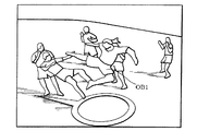
Taking an image generation system capable of enjoying a fighting game as an example, as shown in FIG. 1, a player uses a game controller 10 (operating means in a broad sense; the same applies to the following description) to make an object OB1 (self character). To operate. Then, the user enjoys the game by playing against the object OB2 (enemy character) operated by the opponent player or the computer.
[0004]
In this case, the
[0005]
Such an operation method is effective for a fighting game in which the objects OB1 and OB2 (self character, enemy character) are in a one-on-one battle.
[0006]
However, the operation method as shown in FIG. 1 is not suitable for a type of fighting game (multiplayer fighting game) in which the object OB1 battles against a large number of objects OB2, and the player (operator in a broad sense. There is a technical problem that it is not possible to provide an optimal operating environment (interface environment).
[0007]
The present invention has been made in view of the above problems, and an object of the present invention is to provide an image generation system, a program, and an information storage medium that can provide a suitable operation environment.
[0008]
[Means for Solving the Problems]
In order to solve the above-mentioned problems, the present invention is an image generation system for generating an image, which can be tilted in an arbitrary direction and tilted down and can be detected from a first operation lever capable of detecting an inclination angle. Based on the operation data based on the operation data from the means for causing the first object to make a motion and the second operation lever that can be tilted and tilted in any direction and can detect the tilt angle. , A means for moving the first object, and a means for generating an image including an image of the first object. When the first operating lever is tilted by a given inclination angle, the first operation is performed. The first object is caused to perform an attack motion in an attack direction corresponding to a lever tilt direction. A program according to the present invention causes a computer to function as the above means. An information storage medium according to the present invention is a computer-readable information storage medium, and stores (records) a program for causing a computer to function as the above means.
[0009]
According to the present invention, when the second operating lever is operated and tilted, for example, the first object moves in the moving direction corresponding to the tilting direction. On the other hand, when the first control lever is operated and tilted by a given inclination angle, the first object moves toward the attack direction corresponding to the tilt direction, and the first object moves toward the attack direction (part object or the like toward the attack direction). Perform motions to be fed out).
[0010]
As described above, according to the present invention, only by tilting the first operation lever by a given inclination angle, the first object performs an attack motion toward the attack direction corresponding to the tilt direction. Therefore, it is possible to realize a simple operation environment that is easy for the player to understand intuitively.
[0011]
In addition, the player (operator) can move the first object with the second operation lever while moving the first object with the second operation lever. Can be provided to players.
[0012]
The given tilt angle β1 of the first control lever is expressed as, for example, β1 = βAC × K (K <N), for example, when the maximum tilt angle is βMAX and the accuracy of the tilt angle is βAC = βMAX / N. be able to.
[0013]
In addition, the image generation system, the program, and the information storage medium according to the present invention include at least the distance between the first and second objects and the angle between the direction in which the first object faces and the direction in which the second object exists. According to one of them, the attack motion of the first object is changed.
[0014]
Further, the image generation system, the program, and the information storage medium according to the present invention attack the second object when the second object exists in a given direction range determined by the tilting direction of the first operation lever. It is characterized by causing the first object to perform an attack motion for adding.
[0015]
The image generation system, the program, and the information storage medium according to the present invention include a first time until the first operation lever is tilted by a given inclination angle from the neutral state, and the first operation lever is provided. The attack motion of the first object is changed according to at least one of the second time from the state of being tilted by the inclination angle until it returns to the neutral state by the reaction force.
[0016]
The image generation system, the program, and the information storage medium according to the present invention cause the first object to start an attack motion when the first operation lever is tilted by the first inclination angle, and then the first operation lever When the operation lever is tilted by a second inclination angle larger than the first inclination angle, the direction in which the first object performs an attack motion is determined.
[0017]
The present invention is also an image generation system for generating an image, and is based on operation data from a first operation lever that can be tilted and tilted in an arbitrary direction and can detect an inclination angle. Means for causing one object to perform motion, and means for generating an image including an image of the first object, the distance between the first and second objects, the direction in which the first object faces, and the first The motion of the first object is changed according to at least one of the angles formed with the direction in which the two objects exist. A program according to the present invention causes a computer to function as the above means. An information storage medium according to the present invention is a computer-readable information storage medium, and stores (records) a program for causing a computer to function as the above means.
[0018]
According to the present invention, the distance between the first and second objects, the direction in which the first object faces (for example, the front direction) and the direction in which the second object exists (for example, between the first and second objects) are connected. The motion of the first object changes in various ways according to the angle formed with the direction, the tilt direction, or the action direction. Therefore, various motion expressions can be realized with a simple operation.
[0019]
The present invention is also an image generation system for generating an image, and is based on operation data from a first operation lever that can be tilted and tilted in an arbitrary direction and can detect an inclination angle. Means for causing a motion of one object and means for generating an image including an image of the first object, and the second object is in a given direction range determined by the direction in which the first operating lever is tilted. When present, the first object is caused to perform a motion for applying an action to the second object. A program according to the present invention causes a computer to function as the above means. An information storage medium according to the present invention is a computer-readable information storage medium, and stores (records) a program for causing a computer to function as the above means.
[0020]
According to the present invention, even if the action direction (attack direction, etc.) corresponding to the direction in which the first operating lever is tilted and the direction in which the second object exists are not completely coincident with each other, It is possible to cause the first object to perform a motion to add an action, and the motion of the first object can be determined by a simple process.
[0021]
The image generation system, the program, and the information storage medium according to the present invention are suitable for the first object when the second object does not exist in the given direction range determined by the tilting direction of the first operation lever. The first object is caused to perform a motion corresponding to an angle formed between the direction and the tilting direction of the first operation lever.
[0022]
In this way, the motion of the first object indicating the failure of the action can be expressed realistically.
[0023]
The present invention is also an image generation system for generating an image, and is based on operation data from a first operation lever that can be tilted and tilted in an arbitrary direction and can detect an inclination angle. Means for causing a motion of one object and means for generating an image including an image of the first object, wherein the first operation lever is tilted from the neutral state until it is tilted by a given inclination angle. The motion of the first object is changed according to at least one of the time and the second time from when the first operating lever is tilted by a given inclination angle until the first operating lever returns to the neutral state by the reaction force. It is characterized by that. A program according to the present invention causes a computer to function as the above means. An information storage medium according to the present invention is a computer-readable information storage medium, and stores (records) a program for causing a computer to function as the above means.
[0024]
According to the present invention, the motion of the first object changes according to the tilting time (speed of tilting) and the returning time (speed of returning) of the first operating lever. Therefore, various motion expressions of the first object can be realized in an operation environment in which the player does not feel unnaturalness.
[0025]
The image generation system, the program, and the information storage medium according to the present invention are characterized in that the motion of the first object is changed according to the total time of the first and second times.
[0026]
In this way, it is possible to reduce uncertain elements of time measurement while realizing a quick operation environment.
[0027]
Further, the image generation system, the program, and the information storage medium according to the present invention cause the first object to start the first motion when the first operation lever is tilted by a given inclination angle, When the time, the second time, or the sum of the first and second times is shorter than the given time, the first object is caused to continue the first motion, and the first time, When the second time or the total time of the first and second times is longer than a given time, the first object is caused to perform the second motion.
[0028]
In this way, since the first motion starts when the first operating lever is tilted by a given inclination angle, a quick operating environment can be realized. In addition, since it is determined whether to perform the first or second motion according to the first time, the second time, or the total time, it is possible to reduce various uncertain elements of time measurement. Realize motion expression.
[0029]
The present invention is also an image generation system for generating an image, and is based on operation data from a first operation lever that can be tilted and tilted in an arbitrary direction and can detect an inclination angle. Means for causing a motion of one object and means for generating an image including an image of the first object, and the first object when the first operating lever is tilted by the first inclination angle When the first operation lever is tilted by a second inclination angle larger than the first inclination angle, the direction in which the first object performs the motion is determined. To do. A program according to the present invention causes a computer to function as the above means. An information storage medium according to the present invention is a computer-readable information storage medium, and stores (records) a program for causing a computer to function as the above means.
[0030]
According to the present invention, when the first operating lever is tilted by the first tilt angle, the motion of the first object starts for the time being, so that a quick operating environment can be realized. Subsequently, when the first operating lever is further tilted by the second inclination angle, the direction (motion direction, action direction, attack direction) in which the first object performs a motion is determined. Therefore, even when the operation direction of the first operation lever meanders, it is possible to cause the first object to perform a motion in the direction intended by the player.
[0031]
Further, the image generation system, the program, and the information storage medium according to the present invention provide a tilting direction of the first operating lever when the first operating lever is tilted by a second tilt angle that is larger than the first tilt angle. The correction is performed such that the direction of the first object is directed in the direction corresponding to.
[0032]
In this way, the direction of the first object is changed while performing the motion, and it is possible to realize a motion expression in which the player does not feel uncomfortable.
[0033]
The image generation system, the program, and the information storage medium according to the present invention can be tilted in an arbitrary direction and tilted, and based on operation data from a second operation lever capable of detecting an inclination angle. One object is moved.
[0034]
In this way, it is possible to control the movement of the first object with the second operation lever while controlling the motion of the first object with the first operation lever, thereby providing a suitable operation environment.
[0035]
DETAILED DESCRIPTION OF THE INVENTION
Hereinafter, the present embodiment will be described with reference to the drawings.
[0036]
In addition, this embodiment demonstrated below does not limit the content of this invention described in the claim at all. Further, not all of the configurations described in the present embodiment are essential as a solution means of the present invention.
[0037]
1. Constitution
FIG. 2 shows an example of a functional block diagram of the image generation system (game system) of the present embodiment. In this figure, the present embodiment only needs to include at least the processing unit 100 (or include the
[0038]
The
[0039]
The
[0040]
The information storage medium 180 (computer-readable medium) stores programs, data, and the like, and functions as an optical disk (CD, DVD), magneto-optical disk (MO), magnetic disk, hard disk, and magnetic tape. Alternatively, it can be realized by hardware such as a memory (ROM). The
[0041]
Part or all of the information stored in the
[0042]
The
[0043]
The
[0044]
The portable
[0045]
The
[0046]
A program (data) for causing a computer to function as each unit of the present invention (this embodiment) is distributed from the information storage medium of the host device (server) to the
[0047]
The processing unit 100 (processor) performs various processes such as a game process, an image generation process, and a sound generation process based on operation data from the
[0048]
Here, the processing performed by the
[0049]
The
[0050]
Here, the
[0051]
More specifically, the
[0052]
Pk = Pk-1 + ΔP (1)
θk = θk-1 + △ θ (2)
The
[0053]
More specifically, the motion
[0054]
The motion data stored in the motion
[0055]
In order to reproduce realistic motion with a small amount of motion data, it is desirable to perform motion reproduction using motion interpolation and inverse kinematics.
[0056]
Now, in the present embodiment, the
[0057]
The
[0058]
More specifically, the object is moved toward the moving direction (moving direction corresponding to one arbitrary tilting direction) corresponding to the tilting direction (direction in which the tilting operation is performed) of the analog lever AL2 (second operating lever). Move. In this case, the moving speed of the object may be changed according to the inclination angle of the analog lever AL2. Further, when the object is moved by the analog lever AL2, it is desirable to cause the object to perform a moving motion (such as a walking motion or a running motion) according to the moving speed or the like.
[0059]
The
[0060]
More specifically, the action direction (the action direction corresponding one-to-one with any tilt direction) corresponding to the tilt direction of the analog lever AL1 (direction in which the tilting operation is performed) hits the attack direction, the guard direction, and the ball. The object is caused to perform a motion (action motion) in a direction, a direction of catching a ball, a direction of acquiring an item, or the like. That is, the object is caused to move in the direction of the action by moving a part object (an object such as a limb) of the object or by moving the position of the representative point of the object.
[0061]
Further, in the present embodiment, the distance relationship between the objects (first and second objects), the direction relationship between the objects, the tilting time of the analog lever AL1 (the time until the tilting is performed for a given inclination angle, the speed of the tilting) ) Or the return time of AL1 due to the reaction force (time to return to neutral state from a given tilt angle, return speed), etc., the motion of the object is changed (the motion is made different) .
[0062]
Further, in the present embodiment, the direction range determined by the tilting direction of the analog lever AL1 (the direction range selected according to the tilting direction from a plurality of direction ranges divided in advance) is subject to other actions. It is determined whether or not an object (second object) exists. And when it exists, it makes the object (1st object) perform the action motion which gives an action to another object.
[0063]
In the present embodiment, when the analog lever AL1 is tilted by an inclination angle β1 (for example, an inclination angle for ensuring play), the motion of the object is started (motion playback is started) for the time being. For example, when the analog lever AL1 is further tilted within a predetermined period and the inclination angle β2 (β2> β1) is reached, the motion direction of the object (direction in which an action is performed) is determined.
[0064]
The
[0065]
The
[0066]
Note that the image generation system of the present embodiment may be a system dedicated to the single player mode in which only one player can play, or not only the single player mode but also a multiplayer mode in which a plurality of players can play. The system may also be provided.
[0067]
Further, when a plurality of players play, game images and game sounds to be provided to the plurality of players may be generated using one terminal, or connected via a network (transmission line, communication line) or the like. Alternatively, it may be generated using a plurality of terminals (game machine, mobile phone).
[0068]
2. Features of this embodiment
Next, features of the present embodiment will be described with reference to the drawings. In the following, the case where the present embodiment is applied to a fighting game will be mainly described as an example, but the present embodiment can be widely applied to other games other than the fighting game.
[0069]
2.1 Attack motion by analog lever
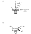
FIG. 3A shows an example of a game controller 30 (operating means in a broad sense, which is also used in the following description) used in the present embodiment. The
[0070]
The analog levers AL1 and AL2 (analog stick, analog direction key) can be tilted and tilted in any direction (from 0 to 360 degrees) as shown in FIG. This is an operation lever that can detect the tilt angle of the hour. In other words, a normal digital (binary) operation lever can detect only binary values such as a value when the lever is in a neutral state and a value when the lever is tilted. On the other hand, the analog levers AL1 and AL2 can detect multi-value (three or more values) inclination angles. For example, when the maximum tilt angle is βMAX, the tilt angle can be detected with an accuracy of βMAX / N (N ≧ 3).
[0071]
More specifically, as shown in FIG. 3B, in this analog lever AL (AL1 or AL2, the same applies to the following description), the inclination angle β of the lever and the tilting direction TD of the lever (for example, the X axis) The formed angle α) can be detected.
[0072]
That is, the analog lever AL includes a first detection device (not shown) that detects a volume value XVL in the X-axis (first axis in a broad sense; the same applies to the following description) direction, and a Z-axis (second in a broad sense). A second detection device (not shown) for detecting the volume value ZVL in the direction is provided. These volume values XVL and ZVL (for example, values of 0 to 255) correspond to the rotation angle around the Z axis and the rotation angle around the X axis, respectively.
[0073]
Then, as shown in FIG. 3C, based on the volume values XVL and ZVL (first and second coordinate components of the operation vector) detected by the first and second detection devices, the analog lever AL Distance D = (XVL) corresponding to the inclination angle β of 2 + ZVL 2 ) 1/2 (Length of the operation vector) is calculated. Further, based on these XVL and ZVL, an angle α = tan corresponding to the tilting direction TD (direction of the operation vector) of the analog lever AL -1 (ZVL / XVL) is calculated.
[0074]
In the present embodiment, object movement processing and motion processing are performed based on the tilt angle β (distance D) and the tilt direction TD (angle α) calculated in this way.
[0075]
Specifically, as shown in FIG. 4A, when the analog lever AL2 (second operation lever) is tilted, the tilt direction is detected, and the object OB1 (operation target) is moved in the moving direction corresponding to the tilt direction. The first object to be (the own character) moves. For example, when the analog lever AL2 is tilted forward / backward / left / right, the object OB1 also moves forward / backward / left / right in the object space. In this case, since the analog lever AL2 can be tilted in an arbitrary direction (0 degree to 360 degrees), the object OB1 can also be moved in an arbitrary movement direction (0 degree to 360 degrees). Further, the moving speed of the object OB1 can be changed based on the inclination angle β of the analog lever AL2.
[0076]
On the other hand, as shown in FIGS. 4B and 4C, when the analog lever AL1 is tilted by a given inclination angle (for example, a slight angle within a range of 0 to 10 degrees), the tilt direction TD is detected. , The object OB1 performs an attack motion (motion or action motion in a broad sense, also in the following description) toward an attack direction AD (in a broad sense, the action direction in the broad sense) corresponding to the defeat direction TD. .
[0077]
For example, in FIG. 4B, since the analog lever AL1 is tilted in the right front direction, the object OB1 performs an attack motion in the right front direction. As a result, the attack hits the object OB2-1 (second object to be acted on) existing in the right front direction.
[0078]
On the other hand, in FIG. 4C, since the analog lever AL1 is tilted in the left rear direction, the object OB1 performs an attack motion in the left rear direction. As a result, the attack hits the object OB2-2 existing in the left rear direction.
[0079]
Thus, in this embodiment, the movement process of the object OB1 is performed based on the operation data from the analog lever AL2, and the motion process of the object OB2 is performed based on the operation data from the analog lever AL1. Therefore, it is possible to provide a player with a preferable operating environment as compared with the conventional operating method described with reference to FIG.
[0080]
That is, in the operation method of FIG. 1, the player cannot explicitly specify the attack direction of the object OB1 (own character). For this reason, the operation environment (interface environment) is difficult for the player to understand intuitively.
[0081]
On the other hand, in the operation method of the present embodiment shown in FIGS. 4A, 4B, and 4C, the attack direction AD (motion direction) of the object OB1 can be explicitly specified by the tilting direction of the analog lever AL1. . Therefore, it is possible to provide an operating environment that is easy for the player to understand intuitively.
[0082]
Further, in the operation method of FIG. 1, it is necessary to make an attack after correcting the object OB1 to face the object OB2 every time it attacks. For example, when the object OB1 wraps behind OB2, it is necessary to attack OB2 after correcting the direction of OB1 from right to left.
[0083]
On the other hand, in the operation method of the present embodiment, it is possible to simultaneously realize the movement operation and the attack operation of the object OB1. That is, it is possible to attack in all directions with one action without correcting the direction of the object OB1 every time it attacks, and the operation method can be simplified.
[0084]
For example, in FIG. 4B, an attack can be applied to the object OB2-1 with a single action of tilting the analog lever AL1 forward rightward without correcting the direction of the object OB1. Similarly, in FIG. 4C, it is possible to attack OB2-2 with one action of simply depressing the analog lever AL1 in the rear left direction.
[0085]
Further, in the operation method of FIG. 1, since the attack direction cannot be explicitly specified, it is not suitable for a type of game (multiplayer fighting game) in which the object OB1 battles against many objects OB2.
[0086]
On the other hand, in the operation method of the present embodiment, an attack can be performed in an arbitrary direction by a simple method, so that it is possible to provide an operation environment suitable for a type of game in which OB1 battles a large number of OB2. That is, as shown in FIGS. 4A, 4B, and 4C, it is possible to realize a game in which the object OB1 operated by the player battles against a large number of enemy objects OB2, thereby increasing the virtual reality of the player. it can.
[0087]
Furthermore, in this embodiment, it becomes possible to compete for the game skill with the accuracy of the direction input of the analog levers AL1 and AL2, and it is possible to provide an operation environment that is easy for the player to understand.
[0088]
As shown in FIGS. 4B and 4C, it is desirable to perform display for representing the attack direction AD (motion direction) of the object OB1. That is, the arrow AH extending from the position of the object OB1 toward the attack direction AD (the direction in which the enemy object exists) is displayed. In this way, the player can immediately and intuitively recognize in which direction he / she has attacked.
[0089]
Note that the arrow AH may be continuously extended according to the inclination angle of the analog lever AL1.
[0090]
In addition, when the inclination angle of the analog lever AL1 becomes a constant angle and it is determined that the input has been established, the image (design) of the arrow AH may be changed to notify the player that the input has been established.
[0091]
Further, when the player continuously tilts the analog lever AL1 in a plurality of directions, the arrow AH may be left in all the directions in which the input is established.
[0092]
Further, when the attack motion of the object OB1 cannot be played in time, or when the attack input cannot be performed, such as when OB1 is damaged, the player is informed that the arrow AH is hidden and the input is impossible. You may make it tell.
[0093]
2.2 Attack motion changes according to distance and direction
In the present embodiment, the attack motion (motion) of OB1 is changed according to at least one of the distance relationship and the direction relationship between the objects OB1 and OB2.
[0094]
That is, as shown in FIG. 5A, the distance R between the objects OB1 and OB2, the direction FD in which OB1 faces (the front direction, the direction in which the eyes and nose face), and the direction in which OB2 exists (the direction OBD connecting between OB1 and OB2, The attack motion of OB1 is changed in accordance with the angle γ formed by the analog lever tilting direction TD or the attack direction AD corresponding to TD.
[0095]
For example, when the object OB2 exists in the right direction of OB1 (γ = 90 degrees), the attack motion is changed as shown in FIG. In other words, when the distance R is a short distance, the OB1 performs an attack motion of a right punch, a right kick when the distance is medium, and a right jump kick motion when the distance is a long distance.
[0096]
When the object OB2 exists in the left direction of OB1 (γ = −90 degrees), for example, the attack motion is changed as shown in FIG. That is, when the distance R is a short distance, the left hook is kicked, when the distance R is a middle distance, the left backward kick is performed, and when the distance R is a long distance, the left step kick is attacked.
[0097]
In this way, the attack motion of the object OB1 changes variously according to the distance R and the angle γ, so that a realistic image with a high game effect effect can be generated by a simple process.
[0098]
That is, in the operation method shown in FIG. 1, only standard attack motions such as right punch, left punch, right kick, and left kick can be expressed by simply pressing the operation buttons 14, 16, 18, and 20. Therefore, in order to cause the object OB1 to perform special attack motions other than these standard attack motions, the player performs a special operation that is a combination of a plurality of button operations or a combination of operation buttons and direction instruction keys. There is a need to do. For example, special operations such as pressing the operation buttons 14 and 16 at the same time or pressing the operation button 18 while pressing the right part of the
[0099]
However, such a special operation does not correspond to the actual movement of the object OB1, and thus has been difficult for the player to understand intuitively. Further, since the player has to master a complicated special operation set for each object, the game operation is difficult, which has been a cause for a beginner to avoid game play.
[0100]
On the other hand, according to the present embodiment, it is possible to cause the object OB1 to perform an optimal attack motion according to the distance R and the angle γ. Therefore, it is possible to realize an operation environment that is easy for the player to understand intuitively. Further, the attack motion of OB1 is automatically determined according to the angle γ determined according to the tilting direction of the analog lever AL1 and the distance R from the enemy OB2. Therefore, even if the player does not acquire a special operation, various attack motions of OB1 can be realized, and a realistic image can be generated in a simple operation environment.
[0101]
Note that the case where the motion of the object OB1 is changed using parameters mathematically equivalent to the distance R and the angle γ is also included in the equivalent range of the present invention.
[0102]
FIG. 6A to FIG. 9 show examples of game images generated by this embodiment.
[0103]
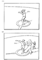
FIG. 6A shows an example of a game image when the object OB1 is standing in the basic posture. In FIG. 6A, the direction in which the eye nose of the object faces (the direction of the arrow displayed on the ground) is the direction in which the object faces (FD in FIG. 5A).
[0104]
FIG. 6B shows an example of a game image when the analog lever is tilted and OB1 is attacking an enemy (object OB2) in the forward direction of the object OB1. As described above, in the present embodiment, the object OB1 performs an attack motion against the enemy only by tilting the analog lever by a slight inclination angle (β1) in the tilt direction corresponding to the enemy existing direction. Therefore, an attack desired by the player can be realized by a single action of simply depressing the analog lever, and an operating environment that is easy for the player to understand intuitively can be provided.
[0105]
FIG. 7A shows an example of a game image when the analog lever is defeated and OB1 is attacking an enemy in the left direction, and FIG. 7B shows OB1 in response to the enemy in the backward direction. It is an example of a game image when is attacking.
[0106]
As is apparent from a comparison between FIGS. 6B, 7A, and 7B, in this embodiment, the attack motion of the object OB1 varies in various ways according to the direction relationship with the enemy. That is, even if the player does not perform complicated special operations, the attack motion of OB1 automatically changes according to the direction relationship with the enemy, and various image expressions can be realized in a simple operation environment.
[0107]
FIG. 8A shows an example of a game image when the distance R between the object OB1 and the enemy (object OB2) is a short distance. Similarly, FIG. 8B and FIG. 9 are examples of game images when the distance R with the enemy is a medium distance and a long distance.
[0108]
As is clear from a comparison of FIGS. 8A, 8B, and 9, in this embodiment, the attack motion of the object OB1 changes according to the distance relationship with the enemy. That is, even if the player does not perform complicated special operations, the attack motion of OB1 automatically changes according to the distance relationship with the enemy, and various image expressions can be realized in a simple operation environment.
[0109]
2.3 Direction range judgment
In this embodiment, the direction range where the object OB2 exists is determined, and the object OB1 is caused to perform an attack motion.
[0110]
More specifically, in FIG. 10A, enemy objects OB2-1 and OB2-2 exist in the direction range DR determined by the tilting direction TD of the analog lever (AL1). Therefore, in this case, the OB1 is caused to perform a motion that applies an attack (action) to the object OB2-1 or OB2-2. Note that whether OB2-1 or OB2-2 is to be attacked is determined based on the distance from OB1, and the one with a short distance may be selected. Alternatively, it may be determined based on the deviation between the tilt direction TD and the direction in which OB2 is present, and the one with a small deviation may be selected.
[0111]
On the other hand, in FIG. 10B, there is no enemy object in the direction range DR determined by the tilting direction of the analog lever. Therefore, in this case, the attack fails and, for example, the object OB1 is caused to perform an idle motion.
[0112]
In this case, in order to express more realistic and diverse images, it is desirable to cause the object OB1 to perform a motion corresponding to the angle γ formed by the direction FD that the object OB1 faces and the analog lever tilting direction TD. .
[0113]
In this way, the motion of the object OB1 changes variously according to the tilting direction TD of the analog lever, and it is possible to effectively prevent the situation where the motion of the OB1 swinging becomes monotonous.
[0114]
As shown in FIG. 10C, a plurality of directional ranges DR0 to DR24 (DR0 to DRM in a broad sense) obtained by dividing a range of 0 degrees to 360 degrees may be set in advance. In this case, an attack motion (motion data) is associated with each of the direction ranges DR0 to DR24. Then, based on the analog lever tilting direction TD, any one of these direction ranges DR0 to DR24 is selected, and the attack motion associated with the selected direction range is reproduced.
[0115]
In this way, the attack motion of the object OB1 can be determined by simple processing, and the processing load can be reduced. Moreover, since it is only necessary to prepare attack motions corresponding to the number of direction ranges, the amount of motion data can be reduced, and the used storage capacity of the memory can be saved.
[0116]
The attack motion of the object OB1 may be determined by performing motion interpolation on the attack motion associated with each direction range.
[0117]
2.4 Motion change according to analog lever defeat time and return time
In the present embodiment, the motion of the object OB1 is changed (the motion is made different) in accordance with the analog lever tilt time (speed to tilt) and return time (speed to return).
[0118]
More specifically, as shown in FIG. 11A, the motion of the object OB1 is changed according to the time T1 until the analog lever AL (AL1) is tilted from the neutral state by the inclination angle β. , The motion of OB1 is changed according to the time T2 from when the AL is tilted by the inclination angle β until it returns to the neutral state due to the reaction force of the AL. Note that β when the analog lever AL is tilted may be different from β when the AL returns.
[0119]
In this way, as shown in FIG. 11B, for example, when the player performs an operation (quick operation) to repel the analog lever AL with a finger or the like, the jab motion (as shown in FIG. (Quick motion) can be performed on the object OB1.
[0120]
That is, as shown in FIG. 11B, when the player quickly operates the analog lever AL by a repelling operation or the like, the times T1 and T2 in FIG. 11A are shortened. When at least one of the times T1 and T2 is short as described above, a jab motion as shown in FIG. 12A (first motion in a broad sense, motion with a short motion playback time, motion with fast operation). The same applies to the following description).
[0121]
On the other hand, when the player operates the analog lever AL at a normal speed, the times T1 and T2 in FIG. 11A are longer than those in the case of the repelling operation. When at least one of the times T1 and T2 is long as described above, a hook motion as shown in FIG. 12B (second motion in a broad sense, motion with a long motion playback time, motion with slow motion). The same applies to the following description).
[0122]
In this way, the motion of the object OB1 changes variously only by changing the speed at which the player operates the analog lever AL. Therefore, it is possible to realize various and realistic image expressions without complicating the operation environment of the player.
[0123]
Note that the motion of the object OB1 may be changed only according to the time T1, or may be changed only according to the time T2. Or you may change according to the total time (time which both T1 and T2 influence) of time T1 and T2.
[0124]
For example, if the first method of changing the motion according to the time T1 is adopted, the speed at which the analog lever AL is tilted can be detected immediately and the jab motion as shown in FIG. 12A can be reproduced. become. Thereby, a quick feeling of operation is realizable.
[0125]
On the other hand, if the second method of changing the motion according to the time T2 is adopted, the uncertain element of the time measurement can be reduced. That is, when the player operates the analog lever AL with an active action, the operation speed (time) varies, and it is difficult to determine whether or not the player has performed a quick operation.
[0126]
On the other hand, the time T2 is the time until the analog lever AL returns to the neutral state due to the reaction force of the elastic body (not shown), and is substantially constant regardless of the speed of the player's operation. Therefore, variation does not easily occur at time T2, and it is easy to determine whether or not the player has performed a quick operation (flick operation). Therefore, in this sense, it is desirable to adopt the second method rather than the first method.
[0127]
In order to utilize the advantages of both the first and second methods, the motion is changed according to the total time of the first and second times (the time affected by both the first and second times). It is desirable to adopt the third method. According to the third method, since the motion changes in consideration of the time T1, a quick operation environment can be realized. In addition, since the motion changes in consideration of the time T2, uncertain elements of time measurement can be reduced.
[0128]
If the analog lever AL is tilted by a given inclination angle β1, the object OB1 starts a jab motion (first motion) for the time being, and then only the given inclination angle β2 (= β). When AL is knocked down, the time T1, T2 or T1 + T2 at that time may be determined, and the started jab motion may be changed.
[0129]
More specifically, when the time T1, T2, or T1 + T2 is short, the object OB1 is continuously subjected to the jab motion as shown in FIG.
[0130]
On the other hand, when the time T1, T2 or T1 + T2 is long, the object OB1 is caused to perform a hook motion (second motion) as shown in FIG. In this case, it is desirable that the joint motion from the jab motion to the hook motion is generated by motion interpolation (interpolation of the joint position of the skeleton model and the angle formed between the bones).
[0131]
In this way, since the motion of the object OB1 starts when the analog lever AL is tilted by a slight inclination angle β1, a quick operation environment can be realized. When the analog lever AL2 is further tilted, the motion of the object OB1 changes according to the tilting speed and the return speed, so that diversification of motion images can be realized.
[0132]
2.5 Start of motion and determination of motion direction
Now, the analog lever AL can be tilted in any direction, and the degree of freedom of operation by the player is high. In other words, the direction in which the analog lever AL is tilted changes in various directions depending on the accuracy of the player's operation, and a meandering operation as shown in FIGS. 13A and 13B is performed. There are many.
[0133]
In such a case, as soon as the player starts to defeat the analog lever AL, the direction in which the AL is tilted is determined, and the direction in which the object OB1 performs the motion (attack direction, action direction) is determined. A situation occurs in which OB1 performs a motion in a direction different from the intended direction.
[0134]
Therefore, in this embodiment, as shown in FIG. 13C, the motion of the object is started for the time being when the analog lever AL (AL1) is tilted by the inclination angle β1 (for example, a slight angle for ensuring play). Like that. In this case, the direction of the motion (attack direction, action direction) performed by the object OB1 is, for example, a tilt direction TD1 (angle α1) when the analog lever AL is tilted by the tilt angle β1, as shown in FIG. Set to the direction corresponding to.
[0135]
Subsequently, when the analog lever AL is further tilted and the inclination angle of AL becomes β2 (β2> β1), the direction in which the object OB1 performs the motion is finally determined. For example, the direction in which the object performs the motion is determined in a direction corresponding to the tilt direction TD2 (angle α2) when the analog lever AL is tilted by the tilt angle β2, as shown in FIG.
[0136]
In this way, since the motion of the object OB1 starts for the time being when the analog lever AL is slightly tilted, a quick operation environment can be provided to the player.
[0137]
And even if the player's operation direction meanders as shown in FIG. 13 (A), the direction corresponding to the final tilting direction (TD2 in FIG. 13 (D)) as shown by E1 in FIG. 13 (B). It is possible to cause the object OB1 to perform a motion toward (attack direction, action direction). Therefore, the object OB1 moves in the direction actually intended by the player, and an operation environment that the player feels more natural can be provided.
[0138]
When the analog lever AL is tilted by the inclination angle β2, it is desirable to correct the direction of the object OB1 in a direction (attack direction, action direction) corresponding to the AL tilting direction TD2 at that time.
[0139]
That is, as shown in FIG. 14, for example, when the orientation of the object OB1 is FD1 when the inclination angle of the analog lever AL is β1, when the inclination angle is β2, the direction FD2 corresponding to the tilting direction at that time Then, the orientation of the object OB1 is corrected. This can be realized by rotating the object OB1 around a given rotation axis (for example, a central axis along the longitudinal direction of OB1). In this way, the direction of the object OB1 is changed while performing the motion, and a motion image in which the player does not feel uncomfortable can be provided.
[0140]
3. Processing of this embodiment
Next, a detailed example of processing according to the present embodiment will be described with reference to the flowcharts of FIGS. 15, 16, and 17.
[0141]
First, it is determined whether or not the analog lever (AL1) has been tilted over an inclination angle β1 (an angle for ensuring play) (step S1). Then, if it is tilted, it is determined whether there is an enemy object in the direction range determined by the tilting direction TD of the analog lever (step S2, FIGS. 10A, 10B, and 10C). reference).
[0142]
If there is an enemy object, the enemy object with the shortest distance in the direction range is selected, and the distance to the enemy object is obtained (step S3). Further, an angle formed by the direction in which the own object (the object operated by the player) faces and the direction (existing direction) of the enemy object viewed from the own object is obtained (step S4). Then, based on the distance obtained in step S3 and the angle obtained in step S4, the attack motion (technique) of the own object is selected (step S5; see FIGS. 5A, 5B, and 5C). ). Then, reproduction of the selected attack motion (successful motion) is started (step S6).
[0143]
On the other hand, if it is determined in step S2 that there is no enemy object in the direction range, the angle formed by the direction in which the object is facing and the direction in which the analog lever is tilted is obtained, The attack motion with the shortest attack time (attack distance) is selected (step S7, see FIG. 10B). Then, the selected attack motion (failed motion, idle motion) is reproduced (step S8).
[0144]
FIG. 16 is a flowchart for realizing the quick motion process by the quick operation (repelling operation) described with reference to FIGS. 11 (A) to 12 (B).
[0145]
First, it is determined whether or not the analog lever (AL1) has been tilted by an inclination angle β1 or more (step S11). And when it is brought down, the jab motion (first motion, quick motion) of FIG. 12A is started for the time being (step S12).
[0146]
Next, it is determined whether or not the total time T1 + T2 (or T1 or T2) described in FIG. 11A is smaller than a certain value (step S13). If it is smaller, the jab motion shown in FIG. 12A is continued (step S14). On the other hand, if it is larger, the jab motion (first motion) is switched to the hook motion (second motion) in FIG. 12B (step S15). At this time, a connection motion between the jab motion and the hook motion is generated by motion interpolation and reproduced.
[0147]
FIG. 17 is a flowchart for realizing the processing described in FIGS. 13A to 14 to start a motion by a slight operation of the analog lever and then determine the motion direction.
[0148]
First, it is determined whether or not the analog lever (AL1) has been tilted by an inclination angle β1 or more (step S21). Then, when it is tilted, it is determined whether or not an enemy object exists within the direction range determined by the tilting direction TD1 of the analog lever (see FIG. 13D) (step S22).
[0149]
If there is an enemy object, the closest enemy object in the direction range is selected, and the distance is obtained (step S23). Further, an angle formed by the direction in which the own object is directed and the direction of the enemy object viewed from the own object is obtained (step S24). Then, based on the distance and angle obtained in steps S23 and S24, the attack motion of the own object is selected and its reproduction is started (step S25).
[0150]
Next, it is determined whether or not the analog lever is tilted by a tilt angle β2 (> β1) or more within a predetermined time after the tilt angle β1 is tilted (step S26). Then, if it is tilted, as described with reference to FIG. 14, the orientation of the own object is corrected in a direction corresponding to the tilting direction TD2 of the analog lever at β2 (see FIG. 13D) (step S27). ). On the other hand, if not defeated, the attack motion in step S25 is continuously reproduced without correcting the direction of the own object (step S28).
[0151]
Next, it is determined whether or not the attack hits an enemy object (step S29). If it hits, it is determined that the attack is successful (step S30), and if it does not hit, the attack fails (empty swing). Determination is made (step S32).
[0152]
On the other hand, if it is determined in step S22 that there is no enemy object in the direction range, the angle between the direction in which the object is facing and the direction in which the analog lever is tilted is obtained, and the attack motion according to the angle The attack motion with the shortest attack time (attack distance) is selected from and the reproduction is started (step S31). In this case, it is determined that the attack has failed (step S32).
[0153]
4). Hardware configuration
Next, an example of a hardware configuration capable of realizing the present embodiment will be described with reference to FIG.
[0154]
The
[0155]
The
[0156]
The
[0157]
The
[0158]
The drawing
[0159]
The
[0160]
Operation data from the game controller 942 (lever, button, chassis, pad type controller, gun type controller, etc.), save data from the
[0161]
The
[0162]
The
[0163]
The
[0164]
The CD drive 980 drives a CD 982 (information storage medium) in which programs, image data, sound data, and the like are stored, and enables access to these programs and data.
[0165]
The
[0166]
Note that all of the means of the present invention may be realized only by hardware, or only by a program stored in an information storage medium or a program distributed via a communication interface. Alternatively, it may be realized by both hardware and a program.
[0167]
When each unit of the present invention is realized by both hardware and a program, a program for causing the hardware (computer) to function as each unit of the present invention is stored in the information storage medium. Become. More specifically, the program instructs each
[0168]
FIG. 19A shows an example in which the present embodiment is applied to an arcade game system (image generation system). The player enjoys the game by operating the
[0169]
FIG. 19B shows an example in which this embodiment is applied to a home game system (image generation system). The player enjoys the game by operating the
[0170]
FIG. 19C shows a
[0171]
In the case of the configuration of FIG. 19C, each unit of the present invention may be realized by being distributed between the host device (server) and the terminal. Further, the above storage program (storage information) for realizing each means of the present invention may be distributed and stored in the information storage medium of the host device (server) and the information storage medium of the terminal.
[0172]
The terminal connected to the network may be a home game system or an arcade game system. When the arcade game system is connected to a network, the save information storage device can exchange information with the arcade game system and exchange information with the home game system. It is desirable to use (memory card, portable game device).
[0173]
The present invention is not limited to that described in the above embodiment, and various modifications can be made.
[0174]
For example, the motion of an object controlled by the operation of an analog lever is not limited to an attack motion, but a guard (defense) motion, a motion to hit (kick) a ball, a motion to catch a ball, or a motion to acquire an item, etc. Various motions (action motions) can be considered.
[0175]
Further, the structure of the first and second operation levers (analog levers) and the method of detecting the tilt angle and the tilting direction are not limited to those described with reference to FIGS. Can be implemented.
[0176]
The parameters for determining or changing the motion (action motion, attack motion) of the object include the parameters described in this embodiment (the tilt angle of the operation lever, the distance between the first and second objects, the first object). Various parameters that are mathematically equivalent to the angle between the direction of the second object and the direction in which the second object exists, the operation lever tilting time, the return time, the total time, and the like.
[0177]
In the invention according to the dependent claims of the present invention, a part of the constituent features of the dependent claims can be omitted. Moreover, the principal part of the invention according to one independent claim of the present invention may be made dependent on another independent claim.
[0178]
The present invention can also be applied to various games (such as fighting games, shooting games, robot battle games, sports games, competitive games, role playing games, music playing games, dance games, etc.).
[0179]
The present invention is also applicable to various image generation systems (game systems) such as a business game system, a home game system, a large attraction system in which a large number of players participate, a simulator, a multimedia terminal, and a system board for generating game images. Applicable.
[Brief description of the drawings]
FIG. 1 is a diagram for explaining a conventional operation method in a fighting game.
FIG. 2 is an example of a functional block diagram of the image generation system of the present embodiment.
FIGS. 3A, 3B, and 3C are diagrams for explaining a method of detecting an inclination angle and a tilting direction of an analog lever.
FIGS. 4A, 4B, and 4C are diagrams for explaining an operation method according to the present embodiment using the analog levers AL1 and AL2. FIGS.
5A, 5B, and 5C change the motion of OB1 depending on the distance between the objects OB1 and OB2 and the angle between the direction in which the object OB1 faces and the direction in which OB2 exists. It is a figure for demonstrating the method made to do.
6A and 6B are examples of game images generated according to the present embodiment.
FIGS. 7A and 7B are examples of game images generated according to the present embodiment.
FIGS. 8A and 8B are examples of game images generated according to the present embodiment.
FIG. 9 is an example of a game image generated according to the present embodiment.
FIGS. 10A, 10B, and 10C are methods for determining the motion of OB1 by determining whether or not object OB2 exists in the direction range determined by the tilting direction of the analog lever. It is a figure for demonstrating.
FIGS. 11A and 11B are diagrams for explaining a method for realizing a quick motion of an object by a quick operation of an analog lever. FIGS.
FIGS. 12A and 12B are examples of game images generated according to the present embodiment.
13 (A), (B), (C), and (D) are diagrams for explaining a method of starting a motion with a slight operation of an analog lever and then determining a motion direction. FIG. .
FIG. 14 is a diagram for explaining a method for correcting the orientation of an object.
FIG. 15 is a flowchart illustrating a detailed example of processing according to the embodiment.
FIG. 16 is a flowchart illustrating a detailed example of processing according to the embodiment.
FIG. 17 is a flowchart illustrating a detailed example of processing according to the embodiment.
FIG. 18 is a diagram illustrating an example of a hardware configuration capable of realizing the present embodiment.
FIGS. 19A, 19B, and 19C are diagrams illustrating examples of various types of systems to which this embodiment is applied.
[Explanation of symbols]
100 processor
110 Movement processing unit
112 Motion processor
120 Image generator
130 Sound generator
160 Operation unit
170 Storage unit
172 Main memory
174 Drawing buffer
176 Motion data storage
180 Information storage medium
190 Display
192 sound output section
194 Portable information storage device
196 Communication Department
Claims (11)
オブジェクトのモーションデータを記憶するモーションデータ記憶手段と、
任意の方向に傾斜させて倒すことが可能であり傾斜角度の検出が可能な第1の操作レバーからの操作データに基づいて、第1のオブジェクトに所与の方向に向けたモーションを行わせるモーション処理手段と、
第1のオブジェクトの画像を含む画像を生成する画像生成手段と、
を含み、
前記モーション処理手段は、
第1の操作レバーが第1の傾斜角度だけ倒された場合に、
第1のオブジェクトにモーションを行わせる方向を、第1の傾斜角度だけ倒された際の第1の操作レバーの倒し方向に対応する方向に設定して、第1のオブジェクトにモーションを開始させ、
その後に第1の操作レバーが第1の傾斜角度よりも大きい第2の傾斜角度だけ倒された場合に、
第1のオブジェクトにモーションを行わせる方向を、第2の傾斜角度だけ倒された際の第1の操作レバーの倒し方向に対応する方向に確定して、第1のオブジェクトにモーションを行わせる
ことを特徴とする画像生成システム。An image generation system for generating an image,
Motion data storage means for storing object motion data;
A motion that allows a first object to perform a motion in a given direction based on operation data from a first operation lever that can be tilted and tilted in an arbitrary direction and that can detect an inclination angle. Processing means;
Image generating means for generating an image including an image of the first object ;
Including
The motion processing means includes
When the first control lever is tilted by the first tilt angle,
The direction in which the first object is caused to perform the motion is set to a direction corresponding to the tilting direction of the first operation lever when the first object is tilted by the first tilt angle, and the first object is started to perform the motion.
Thereafter, when the first operating lever is tilted by a second inclination angle larger than the first inclination angle,
The direction in which the first object is caused to perform motion is determined to be the direction corresponding to the direction in which the first operation lever is tilted when the first tilt angle is tilted, and the first object is caused to perform the motion. An image generation system characterized by the above.
前記モーション処理手段は、
第1の操作レバーが第1の傾斜角度よりも大きい第2の傾斜角度だけ倒された場合に、第1の操作レバーの倒し方向に対応する方向に、第1のオブジェクトの向きを向ける補正を行うことを特徴とする画像生成システム。In claim 1,
The motion processing means includes
When the first operation lever is tilted by a second tilt angle that is larger than the first tilt angle, the first object is corrected in a direction corresponding to the tilt direction of the first operation lever. An image generation system characterized by performing.
前記モーション処理手段は、
第1、第2のオブジェクト間の距離、及び、第1のオブジェクトの向く方向と第2のオブジェクトの存在方向とのなす角度の少なくとも一方に応じて、第1のオブジェクトのモーションを変化させることを特徴とする画像生成システム。In any one of Claims 1 and 2 ,
The motion processing means includes
Changing the motion of the first object according to at least one of a distance between the first and second objects and an angle between the direction in which the first object faces and the direction in which the second object exists. A featured image generation system.
前記モーション処理手段は、
第1の操作レバーの倒し方向により決められる所与の方向範囲に第2のオブジェクトが存在する場合に、該第2のオブジェクトに攻撃を加える攻撃モーションを第1のオブジェクトに行わせることを特徴とする画像生成システム。In any one of Claims 1-3 ,
The motion processing means includes
When the second object exists in a given direction range determined by the tilting direction of the first operation lever, the first object is caused to perform an attack motion that attacks the second object. Image generation system.
前記モーション処理手段は、
第1の操作レバーの倒し方向により決められる所与の方向範囲に第2のオブジェクトが存在しない場合には、第1のオブジェクトの向く方向と第1の操作レバーの倒し方向とのなす角度に応じたモーションを、第1のオブジェクトに行わせることを特徴とする画像生成システム。In claim 4 ,
The motion processing means includes
When the second object does not exist in a given direction range determined by the tilting direction of the first operation lever, it depends on the angle between the direction in which the first object faces and the tilting direction of the first operation lever. An image generation system that causes a first object to perform a predetermined motion.
前記モーション処理手段は、
第1の操作レバーが中立状態から所与の傾斜角度だけ倒されるまでの第1の時間、及び、第1の操作レバーが所与の傾斜角度だけ倒された状態から反力により中立状態に戻るまでの第2の時間の少なくとも一方に応じて、第1のオブジェクトのモーションを変化させることを特徴とする画像生成システム。In any one of Claims 1-5 ,
The motion processing means includes
A first time until the first operating lever is tilted by a given tilt angle from the neutral state, and a state in which the first operating lever is tilted by the given tilt angle returns to the neutral state by a reaction force. An image generation system, wherein the motion of the first object is changed according to at least one of the second times until.
前記モーション処理手段は、
前記第1、第2の時間の総和時間に応じて、第1のオブジェクトのモーションを変化させることを特徴とする画像生成システム。In claim 6 ,
The motion processing means includes
An image generation system, wherein the motion of the first object is changed in accordance with the total time of the first and second times.
前記モーション処理手段は、
第1の操作レバーが所与の傾斜角度だけ倒された場合に、第1のオブジェクトに第1のモーションを開始させ、
第1の時間、第2の時間又は第1、第2の時間の総和時間が所与の時間よりも短い場合には、第1のオブジェクトに第1のモーションを継続して行わせ、
第1の時間、第2の時間又は第1、第2の時間の総和時間が所与の時間よりも長い場合には、第1のオブジェクトに第2のモーションを行わせることを特徴とする画像生成システム。In claim 6 or 7 ,
The motion processing means includes
Causing the first object to start a first motion when the first control lever is tilted by a given tilt angle;
If the first time, the second time or the sum of the first and second times is shorter than a given time, let the first object continue the first motion;
An image characterized by causing a first object to perform a second motion when the first time, the second time, or the sum of the first and second times is longer than a given time. Generation system.
任意の方向に傾斜させて倒すことが可能であり傾斜角度の検出が可能な第2の操作レバーからの操作データに基づいて、第1のオブジェクトを移動させる移動処理部とを更に含むことを特徴とする画像生成システム。In any one of Claims 1-8 ,
A movement processing unit that moves the first object based on operation data from a second operation lever that can be tilted and tilted in an arbitrary direction and that can detect an inclination angle. An image generation system.
任意の方向に傾斜させて倒すことが可能であり傾斜角度の検出が可能な第1の操作レバーからの操作データに基づいて、第1のオブジェクトに所与の方向に向けたモーションを行わせるモーション処理手段と、
第1のオブジェクトの画像を含む画像を生成する画像生成手段として、
コンピュータを機能させるプログラムであって、
前記モーション処理手段は、
第1の操作レバーが第1の傾斜角度だけ倒された場合に、
第1のオブジェクトにモーションを行わせる方向を、第1の傾斜角度だけ倒された際の第1の操作レバーの倒し方向に対応する方向に設定して、第1のオブジェクトにモーションを開始させ、
その後に第1の操作レバーが第1の傾斜角度よりも大きい第2の傾斜角度だけ倒された場合に、
第1のオブジェクトにモーションを行わせる方向を、第2の傾斜角度だけ倒された際の第1の操作レバーの倒し方向に対応する方向に確定して、第1のオブジェクトにモーションを行わせることを特徴とするプログラム。Motion data storage means for storing object motion data;
A motion that allows a first object to perform a motion in a given direction based on operation data from a first operation lever that can be tilted and tilted in an arbitrary direction and that can detect an inclination angle. Processing means;
As an image generation means for generating an image including an image of the first object,
A program that causes a computer to function,
The motion processing means includes
When the first control lever is tilted by the first tilt angle,
The direction in which the first object is caused to perform the motion is set to a direction corresponding to the tilting direction of the first operation lever when the first object is tilted by the first tilt angle, and the first object is started to perform the motion.
Thereafter, when the first operating lever is tilted by a second inclination angle larger than the first inclination angle,
The direction in which the first object is caused to perform motion is determined to be the direction corresponding to the direction in which the first operating lever is tilted when the first tilt angle is tilted, and the first object is caused to perform the motion. A program characterized by
Priority Applications (3)
| Application Number | Priority Date | Filing Date | Title |
|---|---|---|---|
| JP2001227497A JP4187182B2 (en) | 2001-07-27 | 2001-07-27 | Image generation system, program, and information storage medium |
| US10/197,399 US20030040362A1 (en) | 2001-07-27 | 2002-07-18 | Image generation method, program, and information storage medium |
| US12/510,812 US7922584B2 (en) | 2001-07-27 | 2009-07-28 | Image generation method and information storage medium with program for video game in which operation of the controller beyond a predetermined angle causes a character to attack |
Applications Claiming Priority (1)
| Application Number | Priority Date | Filing Date | Title |
|---|---|---|---|
| JP2001227497A JP4187182B2 (en) | 2001-07-27 | 2001-07-27 | Image generation system, program, and information storage medium |
Publications (3)
| Publication Number | Publication Date |
|---|---|
| JP2003044219A JP2003044219A (en) | 2003-02-14 |
| JP2003044219A5 JP2003044219A5 (en) | 2005-10-27 |
| JP4187182B2 true JP4187182B2 (en) | 2008-11-26 |
Family
ID=19060147
Family Applications (1)
| Application Number | Title | Priority Date | Filing Date |
|---|---|---|---|
| JP2001227497A Expired - Lifetime JP4187182B2 (en) | 2001-07-27 | 2001-07-27 | Image generation system, program, and information storage medium |
Country Status (2)
| Country | Link |
|---|---|
| US (2) | US20030040362A1 (en) |
| JP (1) | JP4187182B2 (en) |
Families Citing this family (23)
| Publication number | Priority date | Publication date | Assignee | Title |
|---|---|---|---|---|
| JP2006340791A (en) * | 2005-06-07 | 2006-12-21 | Samii Kk | Game machine |
| JP4445449B2 (en) | 2005-10-04 | 2010-04-07 | 株式会社スクウェア・エニックス | Image generation device |
| JP4187748B2 (en) * | 2006-03-23 | 2008-11-26 | 株式会社コナミデジタルエンタテインメント | Image generating apparatus, image generating method, and program |
| GB2451996B (en) * | 2006-05-09 | 2011-11-30 | Disney Entpr Inc | Interactive animation |
| JP4961172B2 (en) * | 2006-06-27 | 2012-06-27 | オリンパス株式会社 | Information selection system |
| US8628415B2 (en) * | 2006-11-09 | 2014-01-14 | Wms Gaming Inc. | Wagering game with 3D gaming environment using dynamic camera |
| JP2009034375A (en) * | 2007-08-02 | 2009-02-19 | Konami Digital Entertainment:Kk | Game program, game device, and game control method |
| JP5568230B2 (en) * | 2008-10-08 | 2014-08-06 | 株式会社バンダイナムコゲームス | Program, information storage medium, and game system |
| JP5208842B2 (en) | 2009-04-20 | 2013-06-12 | 株式会社カプコン | GAME SYSTEM, GAME CONTROL METHOD, PROGRAM, AND COMPUTER-READABLE RECORDING MEDIUM CONTAINING THE PROGRAM |
| JP4976473B2 (en) * | 2009-09-18 | 2012-07-18 | 株式会社コナミデジタルエンタテインメント | Image generating apparatus, image generating method, and program |
| US20120223953A1 (en) * | 2011-03-04 | 2012-09-06 | Angel Gaming, Llc | Kinematic Engine for Adaptive Locomotive Control in Computer Simulations |
| JP5161384B2 (en) * | 2012-06-11 | 2013-03-13 | 株式会社カプコン | GAME SYSTEM, GAME CONTROL METHOD, PROGRAM, AND COMPUTER-READABLE RECORDING MEDIUM CONTAINING THE PROGRAM |
| JP5161385B2 (en) * | 2012-06-11 | 2013-03-13 | 株式会社カプコン | GAME SYSTEM, GAME CONTROL METHOD, PROGRAM, AND COMPUTER-READABLE RECORDING MEDIUM CONTAINING THE PROGRAM |
| JP5947665B2 (en) * | 2012-08-10 | 2016-07-06 | 株式会社ソニー・インタラクティブエンタテインメント | GAME DEVICE, GAME CONTROL METHOD, AND GAME CONTROL PROGRAM |
| JP5480347B2 (en) * | 2012-08-31 | 2014-04-23 | 株式会社スクウェア・エニックス | Video game processing apparatus and video game processing program |
| FR3031405B1 (en) * | 2015-01-03 | 2018-04-13 | Bigben Interactive Sa | METHOD FOR CONTROLLING A SENSOR CURSOR USING A GAME LEVER AND CORRESPONDING GAME LEVER |
| WO2017029812A1 (en) * | 2015-08-20 | 2017-02-23 | Square Enix Co., Ltd. | Information processing apparatus, information processing method, and non-transitory computer-readable storage medium |
| CN107362535B (en) | 2017-07-19 | 2019-04-26 | 腾讯科技(深圳)有限公司 | Target object locking means, device and electronic equipment in scene of game |
| US10682572B2 (en) * | 2018-07-25 | 2020-06-16 | Cameron Wilson | Video game reticle |
| CN109550238B (en) * | 2018-09-20 | 2022-01-25 | 厦门吉比特网络技术股份有限公司 | Angle correction method and device in game |
| US10974149B2 (en) * | 2019-01-22 | 2021-04-13 | Electronic Arts Inc. | Controlling character movement in a video-game |
| JP7233399B2 (en) * | 2020-06-23 | 2023-03-06 | 任天堂株式会社 | GAME PROGRAM, GAME DEVICE, GAME SYSTEM, AND GAME PROCESSING METHOD |
| JP2023135285A (en) * | 2022-03-15 | 2023-09-28 | 株式会社バンダイナムコアミューズメントラボ | Game device |
Family Cites Families (39)
| Publication number | Priority date | Publication date | Assignee | Title |
|---|---|---|---|---|
| US4546966A (en) * | 1984-06-07 | 1985-10-15 | Segura Perfecto B | Boxer training aid |
| JPS63236128A (en) | 1987-03-25 | 1988-10-03 | Toshiba Corp | Control system for moving speed of cursor display |
| US5012231A (en) * | 1988-12-20 | 1991-04-30 | Golemics, Inc. | Method and apparatus for cursor motion having variable response |
| US5764219A (en) * | 1992-09-25 | 1998-06-09 | Ibm Corporation | Controller for improved computer pointing devices |
| JPH06168070A (en) | 1992-11-30 | 1994-06-14 | Sony Corp | Remote control device |
| JP2799126B2 (en) * | 1993-03-26 | 1998-09-17 | 株式会社ナムコ | Video game device and game input device |
| JPH06315095A (en) | 1993-04-30 | 1994-11-08 | Sony Corp | Remote control system |
| US5624117A (en) * | 1994-07-28 | 1997-04-29 | Sugiyama Electron Co., Ltd. | Game machine controller |
| JPH08281584A (en) | 1995-04-14 | 1996-10-29 | Mitsutoyo Corp | Joy stick signal processing device |
| WO1996036060A1 (en) * | 1995-05-10 | 1996-11-14 | Nintendo Co., Ltd. | Operating device with analog joystick |
| ES2191752T3 (en) * | 1995-05-10 | 2003-09-16 | Nintendo Co Ltd | PICTURE PROCESS SYSTEM USING AN ANALOG CONTROL LEVER. |
| JPH09167050A (en) * | 1995-10-09 | 1997-06-24 | Nintendo Co Ltd | Operation device and image processing system using the device |
| US6219032B1 (en) * | 1995-12-01 | 2001-04-17 | Immersion Corporation | Method for providing force feedback to a user of an interface device based on interactions of a controlled cursor with graphical elements in a graphical user interface |
| AUPN775496A0 (en) * | 1996-01-25 | 1996-02-22 | Aristocrat Leisure Industries Pty Ltd | Touch screen slot machine |
| US5868652A (en) * | 1996-07-08 | 1999-02-09 | Spletzer; David E. | Exercise thigh weight system |
| AUPO429596A0 (en) * | 1996-12-18 | 1997-01-23 | Aristocrat Leisure Industries Pty Ltd | Find the prize |
| JPH10214128A (en) * | 1997-01-30 | 1998-08-11 | Yazaki Corp | Joy stick type multifuctional controller |
| AUPO910297A0 (en) * | 1997-09-10 | 1997-10-02 | Aristocrat Leisure Industries Pty Ltd | Slot machine game - progressive jackpot with decrementing jackpot |
| JPH1176614A (en) | 1997-09-11 | 1999-03-23 | Sega Enterp Ltd | Computer game device |
| JPH11244528A (en) | 1998-03-03 | 1999-09-14 | Junichi Ishihara | Game system played by large number of people |
| JP3844396B2 (en) | 1998-04-24 | 2006-11-08 | 株式会社バンダイナムコゲームス | GAME DEVICE AND INFORMATION STORAGE MEDIUM |
| JPH11342265A (en) * | 1998-06-01 | 1999-12-14 | Sony Computer Entertainment Inc | Record medium and entertainment system |
| JP3191284B2 (en) * | 1998-06-23 | 2001-07-23 | 日本電気株式会社 | Character input device |
| JP4120741B2 (en) | 1998-09-21 | 2008-07-16 | 株式会社セガ | GAME MACHINE, GAME CONTROL METHOD, AND RECORDING MEDIUM CONTAINING PROGRAM |
| JP2000153061A (en) | 1998-11-19 | 2000-06-06 | Nintendo Co Ltd | Video game device and information storage medium for video game |
| JP4616430B2 (en) | 1999-03-16 | 2011-01-19 | 株式会社カプコン | Signal input device |
| EP1058177A1 (en) * | 1999-06-04 | 2000-12-06 | Alps Electric Co., Ltd. | Input device for game machine |
| JP3796707B2 (en) | 1999-06-09 | 2006-07-12 | 株式会社タイトー | Game input device |
| JP2001129252A (en) | 1999-11-02 | 2001-05-15 | Namco Ltd | Game device |
| JP2001149648A (en) * | 1999-12-01 | 2001-06-05 | Namco Ltd | Sport game device |
| JP2001162048A (en) | 1999-12-14 | 2001-06-19 | Namco Ltd | Sport game device and play control method for sport game |
| US20010003708A1 (en) * | 1999-12-10 | 2001-06-14 | Takuya Aizu | Entertainment system, entertainment apparatus, recording medium, and program |
| JP2001009161A (en) | 2000-01-01 | 2001-01-16 | Namco Ltd | Game device |
| US6580418B1 (en) * | 2000-02-29 | 2003-06-17 | Microsoft Corporation | Three degree of freedom mechanism for input devices |
| JP2001318758A (en) * | 2000-03-03 | 2001-11-16 | Sony Computer Entertainment Inc | Operation unit and signal output adjustment method for the unit |
| JP2001314645A (en) * | 2000-05-02 | 2001-11-13 | Konami Co Ltd | Character control method, video game apparatus and recording medium |
| US7182691B1 (en) * | 2000-09-28 | 2007-02-27 | Immersion Corporation | Directional inertial tactile feedback using rotating masses |
| US7137891B2 (en) * | 2001-01-31 | 2006-11-21 | Sony Computer Entertainment America Inc. | Game playing system with assignable attack icons |
| US7321360B1 (en) * | 2004-05-24 | 2008-01-22 | Michael Goren | Systems, methods and devices for efficient communication utilizing a reduced number of selectable inputs |
-
2001
- 2001-07-27 JP JP2001227497A patent/JP4187182B2/en not_active Expired - Lifetime
-
2002
- 2002-07-18 US US10/197,399 patent/US20030040362A1/en not_active Abandoned
-
2009
- 2009-07-28 US US12/510,812 patent/US7922584B2/en not_active Expired - Fee Related
Also Published As
| Publication number | Publication date |
|---|---|
| US7922584B2 (en) | 2011-04-12 |
| US20030040362A1 (en) | 2003-02-27 |
| JP2003044219A (en) | 2003-02-14 |
| US20090286599A1 (en) | 2009-11-19 |
Similar Documents
| Publication | Publication Date | Title |
|---|---|---|
| JP4187182B2 (en) | Image generation system, program, and information storage medium | |
| JP4974319B2 (en) | Image generation system, program, and information storage medium | |
| JP4301471B2 (en) | Image generation system and information storage medium | |
| US6947046B2 (en) | Image generation method, program, and information storage medium | |
| JP3747050B1 (en) | Program, information storage medium, and image generation system | |
| JP3707995B2 (en) | GAME SYSTEM AND INFORMATION STORAGE MEDIUM | |
| JP4758499B2 (en) | Image generation system and information storage medium | |
| JP2003067779A (en) | Image generation system, program and information storage medium | |
| JP2001300143A (en) | Game system and information storage medium | |
| JP4508918B2 (en) | Image generation system and information storage medium | |
| JP2007105499A (en) | Game system, program and information storage medium | |
| JP4662271B2 (en) | Program, information storage medium, and image generation system | |
| US7148894B1 (en) | Image generation system and program | |
| JP2006268511A (en) | Program, information storage medium and image generation system | |
| JP4223139B2 (en) | Image generating apparatus and information storage medium | |
| JP3786671B1 (en) | Program, information storage medium, and image generation system | |
| JP4656622B2 (en) | Image generation system, program, and information storage medium | |
| JP4212015B2 (en) | Image generating apparatus and information storage medium | |
| JP5054908B2 (en) | Program, information storage medium, and image generation system | |
| JP4420729B2 (en) | Program, information storage medium, and image generation system | |
| JP2004057797A (en) | Game system, program, and information storage medium | |
| JP4233065B2 (en) | GAME DEVICE AND INFORMATION STORAGE MEDIUM | |
| JP4785163B2 (en) | Image generation system, program, and information storage medium | |
| JP2002035409A (en) | Game system and information recording medium | |
| JP4641602B2 (en) | GAME SYSTEM AND INFORMATION STORAGE MEDIUM |
Legal Events
| Date | Code | Title | Description |
|---|---|---|---|
| A521 | Request for written amendment filed |
Free format text: JAPANESE INTERMEDIATE CODE: A523 Effective date: 20050905 |
|
| A621 | Written request for application examination |
Free format text: JAPANESE INTERMEDIATE CODE: A621 Effective date: 20050905 |
|
| A977 | Report on retrieval |
Free format text: JAPANESE INTERMEDIATE CODE: A971007 Effective date: 20080206 |
|
| A131 | Notification of reasons for refusal |
Free format text: JAPANESE INTERMEDIATE CODE: A131 Effective date: 20080220 |
|
| A521 | Request for written amendment filed |
Free format text: JAPANESE INTERMEDIATE CODE: A523 Effective date: 20080418 |
|
| A131 | Notification of reasons for refusal |
Free format text: JAPANESE INTERMEDIATE CODE: A131 Effective date: 20080528 |
|
| A521 | Request for written amendment filed |
Free format text: JAPANESE INTERMEDIATE CODE: A523 Effective date: 20080725 |
|
| TRDD | Decision of grant or rejection written | ||
| A01 | Written decision to grant a patent or to grant a registration (utility model) |
Free format text: JAPANESE INTERMEDIATE CODE: A01 Effective date: 20080903 |
|
| A01 | Written decision to grant a patent or to grant a registration (utility model) |
Free format text: JAPANESE INTERMEDIATE CODE: A01 |
|
| A61 | First payment of annual fees (during grant procedure) |
Free format text: JAPANESE INTERMEDIATE CODE: A61 Effective date: 20080905 |
|
| R150 | Certificate of patent or registration of utility model |
Ref document number: 4187182 Country of ref document: JP Free format text: JAPANESE INTERMEDIATE CODE: R150 Free format text: JAPANESE INTERMEDIATE CODE: R150 |
|
| FPAY | Renewal fee payment (event date is renewal date of database) |
Free format text: PAYMENT UNTIL: 20110919 Year of fee payment: 3 |
|
| FPAY | Renewal fee payment (event date is renewal date of database) |
Free format text: PAYMENT UNTIL: 20110919 Year of fee payment: 3 |
|
| FPAY | Renewal fee payment (event date is renewal date of database) |
Free format text: PAYMENT UNTIL: 20110919 Year of fee payment: 3 |
|
| FPAY | Renewal fee payment (event date is renewal date of database) |
Free format text: PAYMENT UNTIL: 20110919 Year of fee payment: 3 |
|
| FPAY | Renewal fee payment (event date is renewal date of database) |
Free format text: PAYMENT UNTIL: 20120919 Year of fee payment: 4 |
|
| R250 | Receipt of annual fees |
Free format text: JAPANESE INTERMEDIATE CODE: R250 |
|
| FPAY | Renewal fee payment (event date is renewal date of database) |
Free format text: PAYMENT UNTIL: 20120919 Year of fee payment: 4 |
|
| FPAY | Renewal fee payment (event date is renewal date of database) |
Free format text: PAYMENT UNTIL: 20130919 Year of fee payment: 5 |
|
| R250 | Receipt of annual fees |
Free format text: JAPANESE INTERMEDIATE CODE: R250 |
|
| R250 | Receipt of annual fees |
Free format text: JAPANESE INTERMEDIATE CODE: R250 |
|
| S533 | Written request for registration of change of name |
Free format text: JAPANESE INTERMEDIATE CODE: R313533 |
|
| R350 | Written notification of registration of transfer |
Free format text: JAPANESE INTERMEDIATE CODE: R350 |
|
| R250 | Receipt of annual fees |
Free format text: JAPANESE INTERMEDIATE CODE: R250 |
|
| S531 | Written request for registration of change of domicile |
Free format text: JAPANESE INTERMEDIATE CODE: R313531 |
|
| R350 | Written notification of registration of transfer |
Free format text: JAPANESE INTERMEDIATE CODE: R350 |
|
| R250 | Receipt of annual fees |
Free format text: JAPANESE INTERMEDIATE CODE: R250 |
|
| R250 | Receipt of annual fees |
Free format text: JAPANESE INTERMEDIATE CODE: R250 |
|
| R250 | Receipt of annual fees |
Free format text: JAPANESE INTERMEDIATE CODE: R250 |
|
| R250 | Receipt of annual fees |
Free format text: JAPANESE INTERMEDIATE CODE: R250 |
|
| R250 | Receipt of annual fees |
Free format text: JAPANESE INTERMEDIATE CODE: R250 |
|
| EXPY | Cancellation because of completion of term |